WO2020189596A1 - ダンプトラックの荷台昇降装置 - Google Patents
ダンプトラックの荷台昇降装置 Download PDFInfo
- Publication number
- WO2020189596A1 WO2020189596A1 PCT/JP2020/011318 JP2020011318W WO2020189596A1 WO 2020189596 A1 WO2020189596 A1 WO 2020189596A1 JP 2020011318 W JP2020011318 W JP 2020011318W WO 2020189596 A1 WO2020189596 A1 WO 2020189596A1
- Authority
- WO
- WIPO (PCT)
- Prior art keywords
- loading platform
- oil
- dump truck
- roll angle
- pair
- Prior art date
- Legal status (The legal status is an assumption and is not a legal conclusion. Google has not performed a legal analysis and makes no representation as to the accuracy of the status listed.)
- Ceased
Links
Images





Classifications
-
- F—MECHANICAL ENGINEERING; LIGHTING; HEATING; WEAPONS; BLASTING
- F15—FLUID-PRESSURE ACTUATORS; HYDRAULICS OR PNEUMATICS IN GENERAL
- F15B—SYSTEMS ACTING BY MEANS OF FLUIDS IN GENERAL; FLUID-PRESSURE ACTUATORS, e.g. SERVOMOTORS; DETAILS OF FLUID-PRESSURE SYSTEMS, NOT OTHERWISE PROVIDED FOR
- F15B11/00—Servomotor systems without provision for follow-up action; Circuits therefor
- F15B11/16—Servomotor systems without provision for follow-up action; Circuits therefor with two or more servomotors
-
- B—PERFORMING OPERATIONS; TRANSPORTING
- B60—VEHICLES IN GENERAL
- B60P—VEHICLES ADAPTED FOR LOAD TRANSPORTATION OR TO TRANSPORT, TO CARRY, OR TO COMPRISE SPECIAL LOADS OR OBJECTS
- B60P1/00—Vehicles predominantly for transporting loads and modified to facilitate loading, consolidating the load, or unloading
- B60P1/04—Vehicles predominantly for transporting loads and modified to facilitate loading, consolidating the load, or unloading with a tipping movement of load-transporting element
- B60P1/16—Vehicles predominantly for transporting loads and modified to facilitate loading, consolidating the load, or unloading with a tipping movement of load-transporting element actuated by fluid-operated mechanisms
-
- B—PERFORMING OPERATIONS; TRANSPORTING
- B60—VEHICLES IN GENERAL
- B60P—VEHICLES ADAPTED FOR LOAD TRANSPORTATION OR TO TRANSPORT, TO CARRY, OR TO COMPRISE SPECIAL LOADS OR OBJECTS
- B60P1/00—Vehicles predominantly for transporting loads and modified to facilitate loading, consolidating the load, or unloading
- B60P1/04—Vehicles predominantly for transporting loads and modified to facilitate loading, consolidating the load, or unloading with a tipping movement of load-transporting element
- B60P1/045—Levelling or stabilising systems for tippers
-
- B—PERFORMING OPERATIONS; TRANSPORTING
- B60—VEHICLES IN GENERAL
- B60P—VEHICLES ADAPTED FOR LOAD TRANSPORTATION OR TO TRANSPORT, TO CARRY, OR TO COMPRISE SPECIAL LOADS OR OBJECTS
- B60P1/00—Vehicles predominantly for transporting loads and modified to facilitate loading, consolidating the load, or unloading
- B60P1/04—Vehicles predominantly for transporting loads and modified to facilitate loading, consolidating the load, or unloading with a tipping movement of load-transporting element
- B60P1/16—Vehicles predominantly for transporting loads and modified to facilitate loading, consolidating the load, or unloading with a tipping movement of load-transporting element actuated by fluid-operated mechanisms
- B60P1/162—Vehicles predominantly for transporting loads and modified to facilitate loading, consolidating the load, or unloading with a tipping movement of load-transporting element actuated by fluid-operated mechanisms the hydraulic system itself
-
- B—PERFORMING OPERATIONS; TRANSPORTING
- B62—LAND VEHICLES FOR TRAVELLING OTHERWISE THAN ON RAILS
- B62D—MOTOR VEHICLES; TRAILERS
- B62D21/00—Understructures, i.e. chassis frame on which a vehicle body may be mounted
- B62D21/18—Understructures, i.e. chassis frame on which a vehicle body may be mounted characterised by the vehicle type and not provided for in groups B62D21/02 - B62D21/17
-
- F—MECHANICAL ENGINEERING; LIGHTING; HEATING; WEAPONS; BLASTING
- F15—FLUID-PRESSURE ACTUATORS; HYDRAULICS OR PNEUMATICS IN GENERAL
- F15B—SYSTEMS ACTING BY MEANS OF FLUIDS IN GENERAL; FLUID-PRESSURE ACTUATORS, e.g. SERVOMOTORS; DETAILS OF FLUID-PRESSURE SYSTEMS, NOT OTHERWISE PROVIDED FOR
- F15B15/00—Fluid-actuated devices for displacing a member from one position to another; Gearing associated therewith
- F15B15/20—Other details, e.g. assembly with regulating devices
-
- F—MECHANICAL ENGINEERING; LIGHTING; HEATING; WEAPONS; BLASTING
- F15—FLUID-PRESSURE ACTUATORS; HYDRAULICS OR PNEUMATICS IN GENERAL
- F15B—SYSTEMS ACTING BY MEANS OF FLUIDS IN GENERAL; FLUID-PRESSURE ACTUATORS, e.g. SERVOMOTORS; DETAILS OF FLUID-PRESSURE SYSTEMS, NOT OTHERWISE PROVIDED FOR
- F15B21/00—Common features of fluid actuator systems; Fluid-pressure actuator systems or details thereof, not covered by any other group of this subclass
- F15B21/08—Servomotor systems incorporating electrically operated control means
- F15B21/087—Control strategy, e.g. with block diagram
-
- F—MECHANICAL ENGINEERING; LIGHTING; HEATING; WEAPONS; BLASTING
- F15—FLUID-PRESSURE ACTUATORS; HYDRAULICS OR PNEUMATICS IN GENERAL
- F15B—SYSTEMS ACTING BY MEANS OF FLUIDS IN GENERAL; FLUID-PRESSURE ACTUATORS, e.g. SERVOMOTORS; DETAILS OF FLUID-PRESSURE SYSTEMS, NOT OTHERWISE PROVIDED FOR
- F15B2211/00—Circuits for servomotor systems
- F15B2211/20—Fluid pressure source, e.g. accumulator or variable axial piston pump
- F15B2211/205—Systems with pumps
- F15B2211/2053—Type of pump
- F15B2211/20546—Type of pump variable capacity
-
- F—MECHANICAL ENGINEERING; LIGHTING; HEATING; WEAPONS; BLASTING
- F15—FLUID-PRESSURE ACTUATORS; HYDRAULICS OR PNEUMATICS IN GENERAL
- F15B—SYSTEMS ACTING BY MEANS OF FLUIDS IN GENERAL; FLUID-PRESSURE ACTUATORS, e.g. SERVOMOTORS; DETAILS OF FLUID-PRESSURE SYSTEMS, NOT OTHERWISE PROVIDED FOR
- F15B2211/00—Circuits for servomotor systems
- F15B2211/30—Directional control
- F15B2211/305—Directional control characterised by the type of valves
- F15B2211/30525—Directional control valves, e.g. 4/3-directional control valve
-
- F—MECHANICAL ENGINEERING; LIGHTING; HEATING; WEAPONS; BLASTING
- F15—FLUID-PRESSURE ACTUATORS; HYDRAULICS OR PNEUMATICS IN GENERAL
- F15B—SYSTEMS ACTING BY MEANS OF FLUIDS IN GENERAL; FLUID-PRESSURE ACTUATORS, e.g. SERVOMOTORS; DETAILS OF FLUID-PRESSURE SYSTEMS, NOT OTHERWISE PROVIDED FOR
- F15B2211/00—Circuits for servomotor systems
- F15B2211/30—Directional control
- F15B2211/305—Directional control characterised by the type of valves
- F15B2211/3056—Assemblies of multiple valves
- F15B2211/30585—Assemblies of multiple valves having a single valve for multiple output members
-
- F—MECHANICAL ENGINEERING; LIGHTING; HEATING; WEAPONS; BLASTING
- F15—FLUID-PRESSURE ACTUATORS; HYDRAULICS OR PNEUMATICS IN GENERAL
- F15B—SYSTEMS ACTING BY MEANS OF FLUIDS IN GENERAL; FLUID-PRESSURE ACTUATORS, e.g. SERVOMOTORS; DETAILS OF FLUID-PRESSURE SYSTEMS, NOT OTHERWISE PROVIDED FOR
- F15B2211/00—Circuits for servomotor systems
- F15B2211/30—Directional control
- F15B2211/315—Directional control characterised by the connections of the valve or valves in the circuit
- F15B2211/3157—Directional control characterised by the connections of the valve or valves in the circuit being connected to a pressure source, an output member and a return line
- F15B2211/31588—Directional control characterised by the connections of the valve or valves in the circuit being connected to a pressure source, an output member and a return line having a single pressure source and multiple output members
-
- F—MECHANICAL ENGINEERING; LIGHTING; HEATING; WEAPONS; BLASTING
- F15—FLUID-PRESSURE ACTUATORS; HYDRAULICS OR PNEUMATICS IN GENERAL
- F15B—SYSTEMS ACTING BY MEANS OF FLUIDS IN GENERAL; FLUID-PRESSURE ACTUATORS, e.g. SERVOMOTORS; DETAILS OF FLUID-PRESSURE SYSTEMS, NOT OTHERWISE PROVIDED FOR
- F15B2211/00—Circuits for servomotor systems
- F15B2211/30—Directional control
- F15B2211/315—Directional control characterised by the connections of the valve or valves in the circuit
- F15B2211/3157—Directional control characterised by the connections of the valve or valves in the circuit being connected to a pressure source, an output member and a return line
- F15B2211/31594—Directional control characterised by the connections of the valve or valves in the circuit being connected to a pressure source, an output member and a return line having multiple pressure sources and multiple output members
-
- F—MECHANICAL ENGINEERING; LIGHTING; HEATING; WEAPONS; BLASTING
- F15—FLUID-PRESSURE ACTUATORS; HYDRAULICS OR PNEUMATICS IN GENERAL
- F15B—SYSTEMS ACTING BY MEANS OF FLUIDS IN GENERAL; FLUID-PRESSURE ACTUATORS, e.g. SERVOMOTORS; DETAILS OF FLUID-PRESSURE SYSTEMS, NOT OTHERWISE PROVIDED FOR
- F15B2211/00—Circuits for servomotor systems
- F15B2211/30—Directional control
- F15B2211/32—Directional control characterised by the type of actuation
- F15B2211/329—Directional control characterised by the type of actuation actuated by fluid pressure
-
- F—MECHANICAL ENGINEERING; LIGHTING; HEATING; WEAPONS; BLASTING
- F15—FLUID-PRESSURE ACTUATORS; HYDRAULICS OR PNEUMATICS IN GENERAL
- F15B—SYSTEMS ACTING BY MEANS OF FLUIDS IN GENERAL; FLUID-PRESSURE ACTUATORS, e.g. SERVOMOTORS; DETAILS OF FLUID-PRESSURE SYSTEMS, NOT OTHERWISE PROVIDED FOR
- F15B2211/00—Circuits for servomotor systems
- F15B2211/40—Flow control
- F15B2211/405—Flow control characterised by the type of flow control means or valve
- F15B2211/40515—Flow control characterised by the type of flow control means or valve with variable throttles or orifices
-
- F—MECHANICAL ENGINEERING; LIGHTING; HEATING; WEAPONS; BLASTING
- F15—FLUID-PRESSURE ACTUATORS; HYDRAULICS OR PNEUMATICS IN GENERAL
- F15B—SYSTEMS ACTING BY MEANS OF FLUIDS IN GENERAL; FLUID-PRESSURE ACTUATORS, e.g. SERVOMOTORS; DETAILS OF FLUID-PRESSURE SYSTEMS, NOT OTHERWISE PROVIDED FOR
- F15B2211/00—Circuits for servomotor systems
- F15B2211/40—Flow control
- F15B2211/415—Flow control characterised by the connections of the flow control means in the circuit
- F15B2211/41527—Flow control characterised by the connections of the flow control means in the circuit being connected to an output member and a directional control valve
-
- F—MECHANICAL ENGINEERING; LIGHTING; HEATING; WEAPONS; BLASTING
- F15—FLUID-PRESSURE ACTUATORS; HYDRAULICS OR PNEUMATICS IN GENERAL
- F15B—SYSTEMS ACTING BY MEANS OF FLUIDS IN GENERAL; FLUID-PRESSURE ACTUATORS, e.g. SERVOMOTORS; DETAILS OF FLUID-PRESSURE SYSTEMS, NOT OTHERWISE PROVIDED FOR
- F15B2211/00—Circuits for servomotor systems
- F15B2211/40—Flow control
- F15B2211/42—Flow control characterised by the type of actuation
- F15B2211/426—Flow control characterised by the type of actuation electrically or electronically
-
- F—MECHANICAL ENGINEERING; LIGHTING; HEATING; WEAPONS; BLASTING
- F15—FLUID-PRESSURE ACTUATORS; HYDRAULICS OR PNEUMATICS IN GENERAL
- F15B—SYSTEMS ACTING BY MEANS OF FLUIDS IN GENERAL; FLUID-PRESSURE ACTUATORS, e.g. SERVOMOTORS; DETAILS OF FLUID-PRESSURE SYSTEMS, NOT OTHERWISE PROVIDED FOR
- F15B2211/00—Circuits for servomotor systems
- F15B2211/40—Flow control
- F15B2211/455—Control of flow in the feed line, i.e. meter-in control
-
- F—MECHANICAL ENGINEERING; LIGHTING; HEATING; WEAPONS; BLASTING
- F15—FLUID-PRESSURE ACTUATORS; HYDRAULICS OR PNEUMATICS IN GENERAL
- F15B—SYSTEMS ACTING BY MEANS OF FLUIDS IN GENERAL; FLUID-PRESSURE ACTUATORS, e.g. SERVOMOTORS; DETAILS OF FLUID-PRESSURE SYSTEMS, NOT OTHERWISE PROVIDED FOR
- F15B2211/00—Circuits for servomotor systems
- F15B2211/60—Circuit components or control therefor
- F15B2211/605—Load sensing circuits
-
- F—MECHANICAL ENGINEERING; LIGHTING; HEATING; WEAPONS; BLASTING
- F15—FLUID-PRESSURE ACTUATORS; HYDRAULICS OR PNEUMATICS IN GENERAL
- F15B—SYSTEMS ACTING BY MEANS OF FLUIDS IN GENERAL; FLUID-PRESSURE ACTUATORS, e.g. SERVOMOTORS; DETAILS OF FLUID-PRESSURE SYSTEMS, NOT OTHERWISE PROVIDED FOR
- F15B2211/00—Circuits for servomotor systems
- F15B2211/60—Circuit components or control therefor
- F15B2211/63—Electronic controllers
- F15B2211/6303—Electronic controllers using input signals
- F15B2211/6306—Electronic controllers using input signals representing a pressure
- F15B2211/6313—Electronic controllers using input signals representing a pressure the pressure being a load pressure
-
- F—MECHANICAL ENGINEERING; LIGHTING; HEATING; WEAPONS; BLASTING
- F15—FLUID-PRESSURE ACTUATORS; HYDRAULICS OR PNEUMATICS IN GENERAL
- F15B—SYSTEMS ACTING BY MEANS OF FLUIDS IN GENERAL; FLUID-PRESSURE ACTUATORS, e.g. SERVOMOTORS; DETAILS OF FLUID-PRESSURE SYSTEMS, NOT OTHERWISE PROVIDED FOR
- F15B2211/00—Circuits for servomotor systems
- F15B2211/60—Circuit components or control therefor
- F15B2211/63—Electronic controllers
- F15B2211/6303—Electronic controllers using input signals
- F15B2211/6336—Electronic controllers using input signals representing a state of the output member, e.g. position, speed or acceleration
-
- F—MECHANICAL ENGINEERING; LIGHTING; HEATING; WEAPONS; BLASTING
- F15—FLUID-PRESSURE ACTUATORS; HYDRAULICS OR PNEUMATICS IN GENERAL
- F15B—SYSTEMS ACTING BY MEANS OF FLUIDS IN GENERAL; FLUID-PRESSURE ACTUATORS, e.g. SERVOMOTORS; DETAILS OF FLUID-PRESSURE SYSTEMS, NOT OTHERWISE PROVIDED FOR
- F15B2211/00—Circuits for servomotor systems
- F15B2211/60—Circuit components or control therefor
- F15B2211/63—Electronic controllers
- F15B2211/6303—Electronic controllers using input signals
- F15B2211/6346—Electronic controllers using input signals representing a state of input means, e.g. joystick position
-
- F—MECHANICAL ENGINEERING; LIGHTING; HEATING; WEAPONS; BLASTING
- F15—FLUID-PRESSURE ACTUATORS; HYDRAULICS OR PNEUMATICS IN GENERAL
- F15B—SYSTEMS ACTING BY MEANS OF FLUIDS IN GENERAL; FLUID-PRESSURE ACTUATORS, e.g. SERVOMOTORS; DETAILS OF FLUID-PRESSURE SYSTEMS, NOT OTHERWISE PROVIDED FOR
- F15B2211/00—Circuits for servomotor systems
- F15B2211/60—Circuit components or control therefor
- F15B2211/665—Methods of control using electronic components
-
- F—MECHANICAL ENGINEERING; LIGHTING; HEATING; WEAPONS; BLASTING
- F15—FLUID-PRESSURE ACTUATORS; HYDRAULICS OR PNEUMATICS IN GENERAL
- F15B—SYSTEMS ACTING BY MEANS OF FLUIDS IN GENERAL; FLUID-PRESSURE ACTUATORS, e.g. SERVOMOTORS; DETAILS OF FLUID-PRESSURE SYSTEMS, NOT OTHERWISE PROVIDED FOR
- F15B2211/00—Circuits for servomotor systems
- F15B2211/60—Circuit components or control therefor
- F15B2211/665—Methods of control using electronic components
- F15B2211/6652—Control of the pressure source, e.g. control of the swash plate angle
-
- F—MECHANICAL ENGINEERING; LIGHTING; HEATING; WEAPONS; BLASTING
- F15—FLUID-PRESSURE ACTUATORS; HYDRAULICS OR PNEUMATICS IN GENERAL
- F15B—SYSTEMS ACTING BY MEANS OF FLUIDS IN GENERAL; FLUID-PRESSURE ACTUATORS, e.g. SERVOMOTORS; DETAILS OF FLUID-PRESSURE SYSTEMS, NOT OTHERWISE PROVIDED FOR
- F15B2211/00—Circuits for servomotor systems
- F15B2211/70—Output members, e.g. hydraulic motors or cylinders or control therefor
- F15B2211/705—Output members, e.g. hydraulic motors or cylinders or control therefor characterised by the type of output members or actuators
- F15B2211/7051—Linear output members
- F15B2211/7053—Double-acting output members
-
- F—MECHANICAL ENGINEERING; LIGHTING; HEATING; WEAPONS; BLASTING
- F15—FLUID-PRESSURE ACTUATORS; HYDRAULICS OR PNEUMATICS IN GENERAL
- F15B—SYSTEMS ACTING BY MEANS OF FLUIDS IN GENERAL; FLUID-PRESSURE ACTUATORS, e.g. SERVOMOTORS; DETAILS OF FLUID-PRESSURE SYSTEMS, NOT OTHERWISE PROVIDED FOR
- F15B2211/00—Circuits for servomotor systems
- F15B2211/70—Output members, e.g. hydraulic motors or cylinders or control therefor
- F15B2211/71—Multiple output members, e.g. multiple hydraulic motors or cylinders
- F15B2211/7107—Multiple output members, e.g. multiple hydraulic motors or cylinders the output members being mechanically linked
-
- F—MECHANICAL ENGINEERING; LIGHTING; HEATING; WEAPONS; BLASTING
- F15—FLUID-PRESSURE ACTUATORS; HYDRAULICS OR PNEUMATICS IN GENERAL
- F15B—SYSTEMS ACTING BY MEANS OF FLUIDS IN GENERAL; FLUID-PRESSURE ACTUATORS, e.g. SERVOMOTORS; DETAILS OF FLUID-PRESSURE SYSTEMS, NOT OTHERWISE PROVIDED FOR
- F15B2211/00—Circuits for servomotor systems
- F15B2211/70—Output members, e.g. hydraulic motors or cylinders or control therefor
- F15B2211/71—Multiple output members, e.g. multiple hydraulic motors or cylinders
- F15B2211/7142—Multiple output members, e.g. multiple hydraulic motors or cylinders the output members being arranged in multiple groups
Definitions
- the present invention relates to a loading platform lifting device for a dump truck.
- Examples of this type of dump truck include super-large dump trucks used in mines and the like as shown in FIGS. 1 and 2. The basic structure of the dump truck will be described based on these figures.
- a loading platform 9 is arranged on the body frame 2 of the dump truck 1.
- the loading platform 9 is connected to the vehicle body frame 2 via a pair of left and right hinges 10 and a pair of left and right hoist cylinders 11 and 12, and the hinges 10 correspond to expansion and contraction of rods 11a and 12a of the hoist cylinders 11 and 12.
- the loading platform 9 moves up and down around the center.
- the dump truck 1 during operation in a mine or the like is, for example, a quarry for crushed stone, earth and sand (hereinafter referred to as excavated material), and is stopped as a seating position where the loading platform 9 is seated on the vehicle body frame 2 as shown in FIG. Then, the excavated material is loaded on the loading platform 9 by a hydraulic excavator or the like.
- the dump truck 1 travels to a predetermined dump truck, and the hoist cylinders 11 and 12 are driven to raise the loading platform 9 to the discharge position shown in FIG.
- the excavated material slides down on the loading platform and is discharged to the ground surface, after which the dump truck 1 switches the loading platform 9 to the seating position and returns to the quarry.
- the loading of the excavated material at the quarry and the discharge of the excavated material at the excavation site are repeated.
- each suspension of the dump truck is acted on based on the detected values of the front and rear pressure sensors provided on the front and rear suspensions of the dump truck and the front-rear tilt angle of the dump truck detected by the tilt sensor.
- the vertical component of the load to be loaded is calculated as the total load at the time of loading, and the total load at the time of loading-the initial load at the time of empty loading is used to obtain the current loading weight of the loading platform.
- the excavated material is not always evenly loaded on the loading platform 9 by a hydraulic excavator or the like, and when the excavated object is biased in the left-right direction and the loading platform 9 is tilted in the left-right direction, the excavated body 9 is tilted from the loading platform 9.
- the loads received by the left and right hoist cylinders 11 become uneven.
- the discharge site is a slope in the left-right direction, the load is also uneven. In such a situation, even if the hydraulic oil is evenly supplied to the left and right hoist cylinders 11 and the loading platform 9 is raised by substantially the same driving force, the load received from the loading platform 9 is uneven, so that the left and right hoist cylinders There is a difference in the extension speed of 11.
- the present invention has been made to solve such a problem, and an object of the present invention is when the excavated material on the loading platform is biased in the left-right direction or when the vehicle is stopped on a slope in the left-right direction. Even if there is, the left and right hoist cylinders can be extended almost evenly while the loading platform is rising to reduce the burden on the hinge connecting the loading platform to the vehicle body frame and prevent damage to the dump truck carrier.
- the purpose is to provide an elevating device.
- the dump truck loading platform lifting device of the present invention connects the loading platform to the vehicle body frame so as to be able to move up and down around a hinge, and hydraulic oil discharged from the hydraulic source in response to the operation of the lifting operation device.
- the flow path of the dump truck is switched by a control valve and supplied to a pair of hoist cylinders arranged at the left and right ends of the loading platform in the vehicle width direction, and the loading platform is raised and lowered according to the expansion and contraction of the hoist cylinders.
- a supply oil amount adjusting unit that can individually adjust the amount of hydraulic oil supplied to the pair of hoist cylinders, a loading platform tilt detecting unit that detects the inclination of the loading platform in the vehicle width direction, and the above.
- a supply oil amount calculation unit that calculates the amount of hydraulic oil supplied to each hoist cylinder based on the inclination of the loading platform detected by the loading platform inclination detection unit, and each of the above calculated units calculated by the supply oil amount calculation unit.
- the hoist cylinder is provided with a supply oil amount control unit that drives and controls the supply oil amount adjustment unit based on the amount of hydraulic oil supplied to the hoist cylinder.
- the loading platform lifting device of the dump truck of the present invention even if the excavated material on the loading platform is biased in the left-right direction or the vehicle is stopped on the slope in the left-right direction, the left and right hoists are hoisted while the loading platform is rising.
- the load on the hinge connecting the loading platform to the vehicle body frame can be reduced and damage can be prevented.
- FIG. 1 is a side view showing a state in which the loading platform of the dump truck to which the loading platform lifting device of the present embodiment is applied is in the seating position
- FIG. 2 is a side view showing a state in which the loading platform of the dump truck is also in the discharging position.
- the dump truck is used for transporting excavated materials (crushed stones, earth and sand, etc.) mined in mines and the like, and in the following description, the front-back, left-right, and up-down directions are expressed mainly by the operator boarding the dump truck.
- the left and right front wheels 4 are supported by the vehicle body frame 2 of the dump truck 1 via the front suspension 3, and the left and right rear wheels 6 (wheels) are supported via the rear suspension 5.
- the front, rear, left and right four wheels 4 and 6 are independently suspended by these four suspensions 3 and 5, respectively, forming a pair of left and right suspension cylinders 7fl and 7fr that constitute the front suspension 3 and the rear suspension 5.
- the pair of left and right suspension cylinders 7rl and 7rr are designed to provide cushioning and damping effects, respectively.
- a loading platform 9 for loading excavated materials is arranged on the vehicle body frame 2, and the loading platform 9 is provided via a pair of left and right hinges 10 and a pair of hoist cylinders 11 and 12 arranged at the left and right ends of the loading platform 9. It is connected to the vehicle body frame 2.
- the loading platform 9 moves up and down between the seating position shown in FIG. 1 and the discharging position shown in FIG. 2 with the hinge 10 as the center according to the expansion / contraction of the rods 11a and 12a of the hoist cylinders 11 and 12. There is.
- An engine 13 which is a prime mover is mounted on the front portion on the vehicle body frame 2, and a driver's cab 8 is provided as a power source for traveling.
- a loading platform 9 described later is moved up and down.
- Various operation devices including the elevating operation device 31 (shown in FIG. 3) for the purpose are provided.
- the excavated material is loaded on a loading platform 9 of a dump truck 1 seated at a seated position by a hydraulic excavator or the like.
- the dump truck 1 travels to the dump truck, switches the loading platform 9 to the discharge position, discharges the excavated material, returns to the quarry, is loaded with crushed stone, and repeats the above operation.
- FIG. 3 is a hydraulic circuit diagram showing the loading platform lifting device of the present embodiment.
- the pair of hydraulic pumps 16 and 17 (hydraulic source, oil supply amount adjusting unit) of the loading platform lifting device 15 are connected to the output shafts 13a of the engine 13 (hydraulic source) described above, and are driven by the engine 13 to drive the hydraulic oil tank.
- the hydraulic oil in 18 is discharged respectively.
- Each of the hydraulic pumps 16 and 17 is configured as a variable displacement type, and the discharge amount of hydraulic oil can be arbitrarily adjusted according to the control of the tilt angle by a regulator (not shown).
- the left and right hoist cylinders 11 and 12 described above are driven by the hydraulic oil supplied from these hydraulic pumps 16 and 17, respectively, and the hydraulic circuits of the hoist cylinders 11 and 12 are provided independently of each other in the same configuration.
- the discharge side of the hydraulic pump 16 is connected to the control valve 20 via the pump line 19, and the control valve 20 is connected to the hydraulic oil tank 18 via the tank line 21. Further, the control valve 20 is connected to the hoist cylinder 11 via a pair of cylinder pipes 22 and 23, one cylinder pipe 22 communicates with the oil chamber 11b on the bottom side, and the other cylinder pipe 23 is a rod. It communicates with the oil chamber 11c on the side.
- the discharge side of the hydraulic pump 17 is connected to the control valve 25 via the pump line 24, and the control valve 25 is connected to the hydraulic oil tank 18 via the tank line 26.
- control valve 25 is connected to the hoist cylinder 12 via a pair of cylinder pipes 27 and 28, one cylinder pipe 27 communicates with the oil chamber 12b on the bottom side, and the other cylinder pipe 28 is a rod. It communicates with the oil chamber 12c on the side.
- the control valves 20 and 25 are configured as, for example, hydraulic pilot type directional control valves, and are in a neutral position, an ascending position, and a descending position according to the input of the pilot pressure to the pair of pilot pressure receiving portions 20a, 20b, 25a, 25b. It can be switched between positions.
- the hydraulic oil from the hydraulic pumps 16 and 17 is shut off, and the inflow and outflow of the hydraulic oil from the oil chambers 11b, 11c, 12b and 12c of the hoist cylinders 11 and 12 are restricted.
- the operating state of the hoist cylinders 11 and 12 at that time, and by extension, the elevating position of the loading platform 9 is maintained.
- the hoist cylinders 11 and 12 are supplied by controlling the tilt angles of the hydraulic pumps 16 and 17.
- the amount of hydraulic oil (supply oil amount VL, VR described later) can be adjusted individually.
- the controller 30 that controls the loading platform lifting device 15 is composed of a CPU 30a (central processing unit), a storage unit 30b (ROM, RAM, non-volatile RAM, etc.), an input / output unit (not shown), and the like.
- An elevating operation device 31 for elevating and lowering the loading platform 9, a loading platform ascending angle detection sensor 32 for detecting the ascending angle ⁇ L of the loading platform 9, and a loading platform tilt detecting unit 33 are connected to the input side of the controller 30.
- the loading platform inclination detection unit 33 plays a role of detecting an index that correlates with the lateral inclination of the loading platform 9 due to the bias of the excavated object loaded on the loading platform 9, but different sensors are used in each of the following embodiments. Therefore, the details will be described for each embodiment.
- the regulators of the hydraulic pumps 16 and 17 described above and the pilot pressure receiving portions 20a, 20b, 25a and 25b of the control valves 20 and 25 are connected to the output side of the controller 30.
- the operation lever 31a of the elevating operation device 31 is switched between the holding position, the raising position, and the lowering position by the operator.
- the controller 30 controls the regulators of the hydraulic pumps 16 and 17 to discharge hydraulic oil, and at the same time, sends a command signal according to the position of the operating lever 31a to the pilots of the control valves 20 and 25.
- the control valves 20 and 25 are switched to the neutral position at the holding position, the control valves 20 and 25 are switched to the rising position at the raising position, and are switched to the lowering position at the lowering position, whereby the operating lever 31a can be operated.
- the hoist cylinders 11 and 12 are driven to move the loading platform 9 up and down.
- the amount of hydraulic oil supplied to the left and right hoist cylinders 11 and 12 is controlled based on an index that correlates with the inclination of the loading platform 9 detected by the loading platform inclination detecting unit 33.
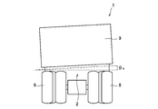
- the roll angle ⁇ R is adopted as an index that correlates with the inclination of the loading platform 9, and as shown in FIG. 4 when the dump truck 1 is viewed from the rear, the roll angle ⁇ R is the loading platform with respect to the vehicle body frame 2. It is a tilt angle in the left-right direction formed by 9.
- a stroke sensor 41 is provided on the front portion of the lower surface of the loading platform 9 as the loading platform inclination detecting unit 33 for detecting the roll angle ⁇ R.
- an optical distance meter may be used, but in a mine where there is a concern that dust adheres to the optical sensor, the wire rod is pulled in by a built-in spring as a more reliable structure, and the wire rod is used.
- a potentiometer (not shown) that can obtain an electric signal corresponding to the amount of withdrawal, fix the tip of the wire near the hoist cylinder connection point on the loading platform 9 side that moves up and down from the seated state, and move the potentiometer to pull in the wire on the vehicle body frame 2 side.
- a stroke sensor may be used which is fixed in the vicinity of the hoist cylinder connection point of the above and is configured so that the distance between the loading platform 9 and the vehicle body frame 2 can be detected with the seated state of the loading platform 9 as the initial state. Since the distances detected by the pair of left and right stroke sensors 41l and 41r correlate with the strokes of the hoist cylinders 11 and 12, respectively, they are referred to as stroke sensors 41l and 41r for detecting the cylinder stroke in the following description. Then, the roll angle ⁇ R of the loading platform 9 is calculated by the controller 30 based on the difference between the cylinder strokes detected by the left and right stroke sensors 41l and 41r (roll angle calculation unit).
- the controller 30 executes the loading platform tilt suppressing routine shown in FIG. 5 at predetermined control intervals.
- the program or the like for executing the routine is stored in the storage unit 30b in advance, and this point is the same for the other embodiments.
- VL the amount of oil supplied to the left hoist cylinder 11
- VR the amount of oil supplied to the right hoist cylinder 12
- the roll angle ⁇ R when the loading platform 9 is in the upward-right posture is given a positive (+) sign
- the roll angle ⁇ R when the loading platform 9 is in the upward-left posture is negative (-). Distinguish by adding a sign.
- step 3 the ascent angle ⁇ L detected by the loading platform ascending angle detection sensor 32 is read, and the roll angle ⁇ R of the loading platform 9 is calculated based on the cylinder strokes detected by the stroke sensors 41l and 41r.
- step 4 it is determined whether or not the absolute value
- the bias determination value ⁇ 2 is a threshold value set based on the lower limit of the roll angle ⁇ R that affects the operation of the hinge 10. When the determination is No (negative), the excavated object is less biased and the hinge 10 operates. It moves to step 5 because it does not affect it.
- step 5 the rising angle ⁇ L detected by the loading platform rising angle detection sensor 32 sets a safety margin from the stroke end, which is the physical extension limit of the hoist cylinders 11 and 12, as a value corresponding to the discharge upper limit position of the loading platform 9 in advance.
- a safety margin from the stroke end, which is the physical extension limit of the hoist cylinders 11 and 12, as a value corresponding to the discharge upper limit position of the loading platform 9 in advance.
- it is determined whether or not it is less than the set discharge upper limit position determination value ⁇ 1 and when the determination is Yes (affirmative), it is assumed that the loading platform 9 has not yet reached the discharge upper limit position, and the process returns to step 2.
- the processes of steps 2 to 5 are repeated and the loading platform 9 continues to rise.
- step 5 when the determination in step 5 becomes No due to the arrival at the discharge upper limit position of the loading platform 9, the flow control of the hydraulic pumps 16 and 17 is stopped in step 6 with the supply oil amounts VL and VR set to 0, and each hoist is stopped in step 7.
- the cylinders 11 and 12 are stopped to end the routine.
- step 8 determines whether or not the roll angle ⁇ R exceeds 0 (whether or not it is a positive value) is determined. judge.
- the process proceeds to step 9, the oil supply amount VL to the left hoist cylinder 11 is increased by a predetermined amount, and the oil supply amount VR to the right hoist cylinder 12 is decreased by a predetermined amount. (Supply oil amount calculation unit), and drives and controls the hydraulic pumps 16 and 17 based on these supply oil amounts VL and VR (supply oil amount control unit).
- step 11 determine whether or not the absolute value
- step 8 the process proceeds to step 10, the oil supply amount VL to the left hoist cylinder 11 is reduced by a predetermined amount, and the oil supply amount VR to the right hoist cylinder 12 is determined. While increasing the amount by a fixed amount (supply oil amount calculation unit), the hydraulic pumps 16 and 17 are driven and controlled (supply oil amount control unit), and then the process proceeds to step 11. In this way, the amount of oil supplied to the left and right hoist cylinders 11 and 12 is appropriately adjusted according to the roll angle ⁇ R, and when the loading platform 9 reaches the discharge upper limit position and the determination in step 5 becomes No, The routine is terminated through the processes of steps 6 and 7.
- FIG. 6 is a time chart showing the control status of the roll angle ⁇ R, the rising angle ⁇ L, and the amount of supplied oil VL, VR based on the above-mentioned loading platform inclination suppressing routine.
- the amount of oil supplied to the left and right hoist cylinders 11 and 12 is controlled to the same value M, but the roll angle ⁇ R gradually becomes positive due to the bias of the excavated material. It is increasing to the side, and it can be inferred that the loading platform 9 is in an upward-sloping posture.
- the left and right hoist cylinders 11 and 12 are substantially equal while the roll angle ⁇ R is changed within the control region defined by ⁇ 2 and ⁇ 2 while the loading platform 9 is rising. Stretch to. During that time, the rising angle ⁇ L continues to increase as the loading platform 9 rises, and when that value reaches the discharge upper limit position determination value ⁇ 1, the loading platform 9 reaches the discharge upper limit position and a series of control ends.
- the rolling angle ⁇ R of the loading platform 9 that affects the hinge 10 is generated while the loading platform 9 is being raised (step of FIG. 5). 4 is Yes), and the amount of oil supplied to the left and right hoist cylinders 11 and 12 VL and VR is increased or decreased so as to reduce the roll angle ⁇ R (steps 8 to 10). Therefore, even if the excavated material on the loading platform 9 is biased in the left-right direction, the roll angle ⁇ R of the loading platform 9 that is rising can be kept within the control region shown in FIG. 6, and the load on the hinge 10 can be maintained. It can be reduced and damage can be prevented.
- the bias determination value ⁇ 2 is set as a fixed value, but for example, the bias determination value ⁇ 2 may be gradually decreased as the rising angle ⁇ L of the loading platform 9 increases. In this case, as shown in FIG. 7, since the control region defined by ⁇ 2 and ⁇ 2 is gradually reduced and the fluctuation range of the roll angle ⁇ R is narrowed, the stress generated in the hinge 10 can be further reduced. ..
- the pressures of the oil chambers 11b and 12b on the bottom side of the left and right hoist cylinders 11 and 12 (hereinafter referred to as hoist cylinder pressures) are adopted as an index that correlates with the inclination of the loading platform 9, and the hoist cylinders.
- a pair of left and right hoist cylinder pressure detection sensors 51l and 51r (shown in FIGS. 1 to 3) are used as the loading platform tilt detection unit 33 to detect the hoist cylinders 11, 12 or the bottom oil chambers 11b and 12b. It is provided in each of the cylinder pipelines 22 and 27 that communicate with each other.
- the hoist cylinder pressure is also distinguished as PL on the left side and PR on the right side.
- the controller 30 executes the loading platform tilt suppressing routine shown in FIG. 8 at predetermined control intervals.
- the loading platform 9 is started to be raised in step 22, and the hoist cylinder pressures PL and PR detected by the left and right hoist cylinder pressure detection sensors 51l and 51r are read in step 23. ..
- the load balance PL / PR in the left-right direction of the loading platform 9 is calculated based on the hoist cylinder pressures PL and PR, and based on the control map shown in FIG. 9 preset in step 25, the load balance PL / PR is left and right.
- the ratio VL / VR of the amount of oil supplied to the hoist cylinders 11 and 12 is calculated.
- step 26 it is determined whether or not the supply oil amount ratio VL / VR is 1 or more, and when the determination of Yes is made, the process proceeds to step 27.
- step 27 after fixing the oil supply amount VL to the left hoist cylinder 11, the oil supply amount VR to the right hoist cylinder 12 is calculated as an achievable value of the supply oil amount ratio VL / VR (supply oil). Amount calculation unit), and drives and controls the hydraulic pumps 16 and 17 based on these oil supply amounts VL and VR (oil supply amount control unit). Further, when the determination of No is made in step 26, the oil supply amount VR on the right side is fixed in step 28, and then the oil supply amount VL on the left side is calculated as a value that can achieve the oil supply amount ratio VL / VR. At the same time (oil supply amount calculation unit), the hydraulic pumps 16 and 17 are driven and controlled (oil supply amount control unit).
- the process proceeds to step 29, and after reading the preset bias determination values f1 (PL / PR) and f2 (PL / PR), the process proceeds to step 30.
- the bias determination values f1 (PL / PR) and f2 (PL / PR) are threshold values that define the allowable region E that does not affect the hinge 10, and the load balance PL. Even if / PR deviates from the solid line in FIG. 9, it can be considered that there is no risk of affecting the hinge 10 if it is located within the allowable region E.
- step 30 the hoist cylinder pressures PL and PR are read again, and in step 31, it is determined whether or not the load balance PL / PR is located within the allowable region E.
- step 32 it is determined in step 32 whether or not the rising angle ⁇ L is less than the discharge upper limit position determination value ⁇ 1, and when the determination is Yes, the process returns to step 30.
- the loading platform 9 continues to rise without further correcting the supplied oil amounts VL and VR.
- the determination in step 32 becomes No, the supply oil amounts VL and VR are set to 0 in step 33, and the hoist cylinders 11 and 12 are stopped in step 34 to end the routine.
- step 31 when the load balance PL / PR deviates from the permissible area E and determines No in step 31, the process returns to step 24.
- the supply oil amount ratio VL / VR can be regarded as inappropriate, the supply oil amount ratio VL / VR is calculated again from the current load balance PL / PR, and the supply oil amounts VL and VR are set again.
- the left and right hoist cylinder pressures PL and PR are used as indexes that correlate with the inclination of the loading platform 9, and the hoist cylinder pressures PL and PR are used.
- the oil supply ratio VL / VR to the left and right hoist cylinders 11 and 12 and the oil supply amount VL and VR are increased or decreased according to the obtained load balance PL / PR (steps 26 to 28). Therefore, although not duplicated, the load on the hinge 10 can be reduced and damage can be prevented.
- the supply oil amount ratio VL / VR deviates from the allowable region E while the loading platform 9 is rising, the supply oil amounts VL and VR are recalculated from the current load balance PL / PR. Therefore, even in such a case, the appropriate supply oil amounts VL and VR can be maintained, and as a result, the hinge 10 can be prevented from being damaged more reliably.
- suspension cylinder pressure the pressure of the oil chamber on the bottom side of the front, rear, left and right suspension cylinders 7fl, 7fr, 7rr, and 7rr (hereinafter referred to as suspension cylinder pressure) is adopted as an index that correlates with the bias of the excavated object.
- a pair of left and right suspension cylinder pressure detection sensors 61fl and 61fr are provided on the front suspension cylinders 7fl and 7fr as the loading platform tilt detection unit 33, and the rear is provided.
- the suspension cylinders 7rl and 7rr on the side are provided with a pair of left and right suspension cylinder pressure detection sensors 61rl and 61rr (shown in FIGS. 1 to 3).
- the suspension cylinder pressure is also distinguished as PFL and PRL on the left side and PFR and PRR on the right side.
- the controller 30 executes the loading platform tilt suppressing routine shown in FIG. 10 at predetermined control intervals.
- the operation to the raised position is performed in step 41, the loading platform 9 starts to rise in step 42, and in step 43, the suspension cylinder pressures PFL, PFR on the front side, the suspension cylinders 7fl and 7fr on the front side, and the suspension cylinder on the rear side.
- the suspension cylinder pressures PRL and PRR of 7rr and 7rr are read.
- the load balance PL / PR is calculated.
- the front and rear suspension cylinder pressures PFL and PRL on the left side are added to obtain the suspension cylinder pressure PL on the left side
- the front and rear suspension cylinder pressures PFR and PRR on the right side are added to obtain the suspension cylinder pressure PR on the right side. Then, let these ratios be the load balance PL / PR.
- the left and right oil supply ratio VL / VR is calculated from the load balance PL / PR in step 45, and the oil supply ratio VL / VR is 1 in step 46. It is determined whether or not it is the above. Then, when the determination in step 46 is Yes, the oil supply amount VR on the left side is fixed in step 47, and then the oil supply amount VR on the right side is calculated as a value satisfying the condition of the oil supply amount ratio VL / VR (supply). Oil amount calculation unit), and drives and controls the hydraulic pumps 16 and 17 based on these oil supply amounts VL and VR (oil supply amount control unit).
- step 46 When the determination in step 46 is No, the oil supply amount VR on the right side is fixed in step 48, and then the oil supply amount VL on the left side is calculated as a value satisfying the condition of the oil supply amount ratio VL / VR (supply). Oil amount calculation unit), drives and controls the hydraulic pumps 16 and 17 (oil supply amount control unit).
- step 49 it is determined whether or not any of the rear suspension cylinder pressures PRL and PRR is less than the preset discharge start judgment value P1 (discharge start judgment unit).
- the discharge start determination value P1 is a threshold value for determining the discharge start of the excavated object from the loading platform 9.
- the suspension cylinder pressures PRL and PRR on the rear side sharply decrease and fall below the discharge start determination value P1. Therefore, it can be considered that the discharge of the excavated material has started when the judgment of Yes is made in step 49, and in this case, the process proceeds to step 50.
- step 50 a preset correction value is subtracted from the supplied oil amounts VL and VR.
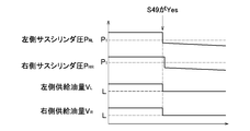
- FIG. 11 is a time chart showing the control status of the suspension cylinder pressures PF and PR and the supply oil amounts VL and VR when the suspension cylinder pressure PRL on the left side becomes less than the discharge start determination value P1 in advance.
- the supply oil amounts VL and VL are reduced and corrected to L by the process of step 50.
- the flow control of the hydraulic pumps 16 and 17 is stopped in step 52, and the hoist cylinders 11 and 12 are stopped in step 53 to end the routine. To do.
- the suspension cylinder pressures PFL, PFR, PRL, and PRR of the front, rear, left, and right suspension cylinders 7fl, 7fr, 7rl, and 7rr are used as indexes that correlate with the inclination of the loading platform 9, and the suspension cylinder pressure PFL.
- the ratio of the amount of oil supplied to the left and right hoist cylinders 11 and 12 VL / VR, and eventually the amount of oil supplied VL, VR is increased or decreased according to the load balance PL / PR obtained from PFR, PRL, and PRR (steps 46 to 46). 48). Therefore, although not duplicated, the load on the hinge 10 can be reduced and damage can be prevented.
- the start of discharge of the excavated material from the loading platform 9 is determined based on the comparison between the suspension cylinder pressures PRL and PRR on the rear side and the discharge start judgment value P1 (step 49), and the oil supplied to the left and right hoist cylinders 11 and 12 is determined.
- the quantities VL and VL are subtracted (step 50).
- the center of gravity of the loading platform 9 was located in front of the hinge 10 before the excavated material was discharged from the ascending loading platform 9, whereas the center of gravity suddenly hinged immediately after the excavated material was discharged. Move to the rear side of 10. This movement of the center of gravity causes a phenomenon called kickback, and the load acting on the hoist cylinders 11 and 12 is reversed, and an excessive load is applied to the vehicle body.
- the processing of steps 29 to 31 of FIG. 8 regarding the allowable area E may be added between steps 48 and 49 in the flowchart of FIG. 10, and no overlapping explanation will be given, but in this case, the second The action and effect described in the embodiment can be obtained.
- the aspect of the present invention is not limited to this embodiment.
- the excavated object on the loading platform 9 is biased in the left-right direction, but it may be embodied as a countermeasure assuming, for example, the dump truck 1 is stopped on the slope in the left-right direction. ..
- the causes are different between the two, the loads received by the left and right hoist cylinders 11 and 12 become uneven due to the inclination generated in the loading platform 9, which causes a difference in the extension speeds of the left and right hoist cylinders 11 and 12. It is common in that it occurs and the load on the hinge 10 increases.
- the hydraulic circuits of the left and right hoist cylinders 11 and 12 are provided independently, but the present invention is not limited to this.
- the hydraulic oil discharged from the single hydraulic pump 16 (hydraulic source) driven by the engine 13 is also supplied to the single control valve 20 to operate the elevating operation device 31.
- the control valve 20 may be switched accordingly.
- the hydraulic oil from the control valve 20 is branched and supplied to a pair of electromagnetic proportional flow control valves 71 and 72 (supply oil amount adjusting unit), and the opening degree of these flow control valves 71 and 72 is supplied as the supply oil.
- the amount of oil supplied to the left and right hoist cylinders 11 and 12 may be increased or decreased by controlling according to the amount ratio VL / VR. Even in this case, the same action and effect as those of each of the above embodiments can be obtained.
Landscapes
- Engineering & Computer Science (AREA)
- Mechanical Engineering (AREA)
- Transportation (AREA)
- Physics & Mathematics (AREA)
- Fluid Mechanics (AREA)
- General Engineering & Computer Science (AREA)
- Chemical & Material Sciences (AREA)
- Analytical Chemistry (AREA)
- Combustion & Propulsion (AREA)
- Fluid-Pressure Circuits (AREA)
- Component Parts Of Construction Machinery (AREA)
- Vehicle Body Suspensions (AREA)
Abstract
上昇中の荷台(9)に掘削物の偏りにより左右方向の傾きが生じている場合に傾きをロール角(θR)として検出し、その絶対値(|θR|)が偏り判定値(θ2)以上か否かを判定する(S4)。偏り判定値(θ2)以上であり(S4がYes)、ロール角(θR)が正の場合(荷台(9)が右上がり)には(S8がYes)、左側のホイストシリンダ(11)への供給油量(VL)を増加させ、右側のホイストシリンダ(12)への供給油量(VR)を減少させる(S9)。またロール角(θR)が負の場合(荷台(9)が左上がり)には(S8がNo)、左側の供給油量(VL)を減少させ、右側の供給油量(VR)を増加させる(S10)。
Description
本発明は、ダンプトラックの荷台昇降装置に関する。
この種のダンプトラックとして、例えば図1,2に示すような鉱山等で使用される超大型のダンプトラックを挙げることができる。これらの図に基づきダンプトラックの基本構造を説明する。
ダンプトラック1の車体フレーム2上には荷台9が配設されている。荷台9は左右1対のヒンジ10及び左右1対のホイストシリンダ11,12を介して車体フレーム2に連結され、各ホイストシリンダ11,12のロッド11a,12aの伸張・縮退に応じて、ヒンジ10を中心として荷台9が昇降するようになっている。
鉱山等での稼働時のダンプトラック1は、例えば砕石や土砂等(以下、掘削物と称する)の採掘場で、荷台9を図1に示すように車体フレーム2に着座させた着座位置として停車し、荷台9上に油圧ショベル等により掘削物が積み込まれる。積込みを完了するとダンプトラック1は所定の放土場まで走行し、ホイストシリンダ11,12の駆動により荷台9を図2の排出位置へと上昇させる。これにより掘削物は荷台上を滑り落ちて地表に排出され、その後にダンプトラック1は荷台9を着座位置に切り換えて採掘場に戻る。以上のようにして、採掘場での掘削物の積込及び放土場での掘削物の排出が繰り返される。
ダンプトラック1による掘削物の運搬効率を高めるには、予め定められた定格積載重量まで荷台上に掘削物を積込むことが重要であり、そのための技術として特許文献1に記載のものが提案されている。
この特許文献1の技術では、ダンプトラックの前後のサスペンションに設けたフロント及びリア圧力センサの検出値と、傾斜センサにより検出されるダンプトラックの前後傾斜角とに基づき、ダンプトラックの各サスに作用する荷重の垂直方向成分を積載時の総荷重として求め、積載時の総加重-空荷時の初期荷重に基づき現在の荷台の積載重量を求めている。
ところで、荷台9を円滑に昇降させるために左右のホイストシリンダ11,12には均等に作動油が供給され、略同一の駆動力を荷台9に伝達するように配慮されている。しかしながら、この対策は、左右のホイストシリンダ11,12が荷台9から均等な荷重を受けていることが前提であり、以下に述べる状況では問題が生じる。
例えば、油圧ショベル等により荷台9上に掘削物が常に均等に積み込まれるとは限らず、左右方向への掘削物の偏りが生じて荷台9が左右方向に傾いている場合には、荷台9から左右のホイストシリンダ11が受ける荷重が不均等になる。また、放土場が左右方向の斜面である場合にも、同じく荷重の不均等が生じる。このような状況において、左右のホイストシリンダ11に均等に作動油が供給されて略同一の駆動力により荷台9を上昇させたとしても、荷台9から受ける荷重が不均等なため、左右のホイストシリンダ11の伸張速度に格差が生じる。
このような伸張速度の格差は荷台9を左右に傾け、荷台9を車体フレーム2に連結するヒンジ10に過大な応力が生じ、掘削物の排出動作の繰り返しにより破損の要因になるという問題があった。特許文献1では車体の前後方向の傾斜角度を検出しているが、それはあくまで荷重の垂直方向の成分を算出するためであり、荷台自体の左右方向への傾きについては何ら考慮されていない。
本発明はこのような問題点を解決するためになされたもので、その目的とするところは、荷台上の掘削物に左右方向への偏りがある場合、或いは左右方向の斜面に停車した場合であっても、荷台の上昇中に左右のホイストシリンダを略均等に伸張させて、荷台を車体フレームに連結しているヒンジの負担を軽減して破損を未然に防止することができるダンプトラックの荷台昇降装置を提供することにある。
上記の目的を達成するため、本発明のダンプトラックの荷台昇降装置は、車体フレームにヒンジを中心として荷台を昇降可能に連結し、昇降操作装置の操作に応じて油圧源から吐出される作動油の流路を制御弁により切り換えて、車幅方向において前記荷台の左右端部に配置した1対のホイストシリンダにそれぞれ供給し、前記ホイストシリンダの伸張・縮退に応じて荷台を昇降させるダンプトラックの荷台昇降装置において、前記1対のホイストシリンダへの作動油の供給油量を個別に調整可能な供給油量調整部と、前記荷台の車幅方向の傾きを検出する荷台傾き検出部と、前記荷台傾き検出部により検出された前記荷台の傾きに基づき、前記各ホイストシリンダへの作動油の供給油量をそれぞれ算出する供給油量算出部と、前記供給油量算出部により算出された前記各ホイストシリンダへの作動油の供給油量に基づき、前記供給油量調整部を駆動制御する供給油量制御部とを備えたことを特徴とする。
本発明のダンプトラックの荷台昇降装置によれば、荷台上の掘削物に左右方向への偏りがある場合、或いは左右方向の斜面に停車した場合であっても、荷台の上昇中に左右のホイストシリンダを略均等に伸張させて、荷台を車体フレームに連結しているヒンジの負担を軽減して破損を未然に防止することができる。
以下、本発明を具体化したダンプトラックの荷台昇降装置の一実施形態を説明する。
図1は本実施形態の荷台昇降装置が適用されたダンプトラックの荷台を着座位置とした状態を示す側面図、図2は同じくダンプトラックの荷台を排出位置とした状態を示す側面図である。ダンプトラックは、鉱山等で採掘された掘削物(砕石や土砂等)の運搬に使用され、以下の説明では、ダンプトラックに搭乗したオペレータを主体として前後、左右、上下方向を表現する。
図1は本実施形態の荷台昇降装置が適用されたダンプトラックの荷台を着座位置とした状態を示す側面図、図2は同じくダンプトラックの荷台を排出位置とした状態を示す側面図である。ダンプトラックは、鉱山等で採掘された掘削物(砕石や土砂等)の運搬に使用され、以下の説明では、ダンプトラックに搭乗したオペレータを主体として前後、左右、上下方向を表現する。
ダンプトラック1の車体フレーム2には、フロントサスペンション3を介して左右の前輪4(車輪)が支持されると共に、リアサスペンション5を介して左右の後輪6(車輪)が支持されている。これらの4つサスペンション3,5により前後左右の4つの車輪4,6がそれぞれ独立懸架され、フロント側のサスペンション3を構成する左右1対のサスペンションシリンダ7fl,7fr、及びリア側のサスペンション5を構成する左右1対のサスペンションシリンダ7rl,7rrにより、それぞれ緩衝作用及び減衰作用が奏されるようになっている。車体フレーム2上には掘削物を積載する荷台9が配設され、荷台9は、左右1対のヒンジ10及び荷台9の左右端部に配置された1対のホイストシリンダ11,12を介して車体フレーム2に連結されている。各ホイストシリンダ11,12のロッド11a,12aの伸張・縮退に応じて、ヒンジ10を中心として荷台9が図1に示す着座位置と図2に示す排出位置との間で昇降するようになっている。
車体フレーム2上の前部には、走行用動力源として原動機であるエンジン13が搭載されると共に、運転室8が設けられており、運転室8内には、後述する荷台9を昇降操作するための昇降操作装置31(図3に示す)を含む各種操作機器が設けられている。
鉱山等において掘削物が掘削される採掘場では、着座位置に着座させているダンプトラック1の荷台9上に油圧ショベル等により掘削物が積載される。積載を完了するとダンプトラック1は放土場まで走行し、荷台9を排出位置に切り換えて掘削物を排出した後、採掘場に戻って砕石等が積載され、以上の動作を繰り返す。
鉱山等において掘削物が掘削される採掘場では、着座位置に着座させているダンプトラック1の荷台9上に油圧ショベル等により掘削物が積載される。積載を完了するとダンプトラック1は放土場まで走行し、荷台9を排出位置に切り換えて掘削物を排出した後、採掘場に戻って砕石等が積載され、以上の動作を繰り返す。
図3は本実施形態の荷台昇降装置を示す油圧回路図である。
荷台昇降装置15の1対の油圧ポンプ16,17(油圧源、供給油量調整部)は上記したエンジン13(油圧源)の出力軸13aにそれぞれ接続され、エンジン13により駆動されて作動油タンク18内の作動油をそれぞれ吐出する。各油圧ポンプ16,17は可変容量型として構成され、図示しないレギュレータによる傾転角の制御に応じて作動油の吐出量を任意に調整可能となっている。これらの油圧ポンプ16,17から供給される作動油により上記した左右のホイストシリンダ11,12がそれぞれ駆動され、各ホイストシリンダ11,12の油圧回路は同一構成で互いに独立して設けられている。
荷台昇降装置15の1対の油圧ポンプ16,17(油圧源、供給油量調整部)は上記したエンジン13(油圧源)の出力軸13aにそれぞれ接続され、エンジン13により駆動されて作動油タンク18内の作動油をそれぞれ吐出する。各油圧ポンプ16,17は可変容量型として構成され、図示しないレギュレータによる傾転角の制御に応じて作動油の吐出量を任意に調整可能となっている。これらの油圧ポンプ16,17から供給される作動油により上記した左右のホイストシリンダ11,12がそれぞれ駆動され、各ホイストシリンダ11,12の油圧回路は同一構成で互いに独立して設けられている。
油圧ポンプ16の吐出側はポンプ管路19を介して制御弁20と接続され、制御弁20はタンク管路21を介して作動油タンク18と接続されている。また、制御弁20は1対のシリンダ管路22,23を介してホイストシリンダ11と接続され、一方のシリンダ管路22はボトム側の油室11bと連通し、他方のシリンダ管路23はロッド側の油室11cと連通している。
油圧ポンプ17の吐出側はポンプ管路24を介して制御弁25と接続され、制御弁25はタンク管路26を介して作動油タンク18と接続されている。また、制御弁25は1対のシリンダ管路27,28を介してホイストシリンダ12と接続され、一方のシリンダ管路27はボトム側の油室12bと連通し、他方のシリンダ管路28はロッド側の油室12cと連通している。
油圧ポンプ17の吐出側はポンプ管路24を介して制御弁25と接続され、制御弁25はタンク管路26を介して作動油タンク18と接続されている。また、制御弁25は1対のシリンダ管路27,28を介してホイストシリンダ12と接続され、一方のシリンダ管路27はボトム側の油室12bと連通し、他方のシリンダ管路28はロッド側の油室12cと連通している。
制御弁20,25は、例えば油圧パイロット式方向制御弁として構成され、1対のパイロット受圧部20a,20b,25a,25bへのパイロット圧の入力に応じて中立位置、上昇位置、下降位置の3位置間で切り換えられる。制御弁20,25の中立位置では油圧ポンプ16,17からの作動油が遮断され、ホイストシリンダ11,12の油室11b,11c,12b,12cからの作動油の流入及び流出が規制されることにより、その時点のホイストシリンダ11,12の作動状態、ひいては荷台9の昇降位置が保持される。
制御弁20,25が上昇位置に切り換えられると、油圧ポンプ16,17からの作動油が一方のシリンダ管路22,27を経てホイストシリンダ11,12のボトム側の油室11b,12bに供給され、ロッド11a,12aの伸張により荷台9が上昇すると共に、ロッド側の油室11c,12cの作動油が他方のシリンダ管路23,28及びタンク管路21,26を経て作動油タンク18に戻される。また、制御弁20,25が下降位置に切り換えられると、油圧ポンプ16,17からの作動油が他方のシリンダ管路23,28を経てホイストシリンダ11,12のロッド側の油室11c,12cに供給され、ロッド11a,12aの縮退により荷台9が下降すると共に、ボトム側の油室11b,12bの作動油が一方のシリンダ管路22,27及びタンク管路21,26を経て作動油タンク18に戻される。
そして本実施形態では、各ホイストシリンダ11,12の油圧回路が独立していることから、それぞれの油圧ポンプ16,17の傾転角を制御することにより、各ホイストシリンダ11,12に供給される作動油の量(後述する供給油量VL,VR)を個別に調整可能となっている。
図3に示すように、荷台昇降装置15を制御するコントローラ30は、CPU30a(中央演算処理装置)、記憶部30b(ROM、RAM、不揮発性RAM等)及び図示しない入出力部等から構成されている。コントローラ30の入力側には、荷台9を昇降操作するための昇降操作装置31、荷台9の上昇角θLを検出する荷台上昇角検出センサ32、及び荷台傾き検出部33が接続されている。荷台傾き検出部33は、荷台9に積載された掘削物の偏りに起因する荷台9の左右方向の傾きと相関する指標を検出する役割を果たすが、以下に述べる各実施形態で異なるセンサを用いているため、その詳細については実施形態毎に説明する。
またコントローラ30の出力側には、上記した各油圧ポンプ16,17のレギュレータ、及び各制御弁20,25のパイロット受圧部20a,20b,25a,25bが接続されている。
またコントローラ30の出力側には、上記した各油圧ポンプ16,17のレギュレータ、及び各制御弁20,25のパイロット受圧部20a,20b,25a,25bが接続されている。
昇降操作装置31の操作レバー31aは、オペレータにより保持位置、上げ位置、下げ位置の3位置間で切り換えられる。操作レバー31aが操作されると、コントローラ30は各油圧ポンプ16,17のレギュレータを制御して作動油を吐出させると共に、操作レバー31aの位置に応じた指令信号を各制御弁20,25のパイロット受圧部20a,20b,25a,25bに出力して切り換える。詳しくは、保持位置では制御弁20,25が中立位置に切り換えられ、上げ位置では制御弁20,25が上昇位置に切り換えられ、下げ位置では下降位置に切り換えられ、これにより操作レバー31aの操作に応じてホイストシリンダ11,12の駆動により荷台9の昇降が行われる。
そして、[発明が解決しようとする課題]で述べたように、荷台9の上昇時において荷台9上の掘削物に左右方向への偏りがあると、荷台9から受ける荷重の不均等に起因して左右のホイストシリンダ11,12の伸張速度に格差が生じ、荷台9を車体フレーム2に連結しているヒンジ10に過大な応力が発生するという問題がある。
そこで本発明では、荷台傾き検出部33により検出される荷台9の傾きと相関する指標に基づき、左右のホイストシリンダ11,12に供給する作動油の量を制御しており、その詳細を第1~3実施形態として以下に説明する。
そこで本発明では、荷台傾き検出部33により検出される荷台9の傾きと相関する指標に基づき、左右のホイストシリンダ11,12に供給する作動油の量を制御しており、その詳細を第1~3実施形態として以下に説明する。
[第1実施形態]
本実施形態では、荷台9の傾きと相関する指標としてロール角θRを採用しており、ダンプトラック1を後方より見た図4に示すように、ロール角θRは、車体フレーム2に対して荷台9が形成する左右方向の傾き角度である。ロール角θRの検出のために、荷台傾き検出部33として、荷台9の下面前部にはストロークセンサ41が設けられている。
本実施形態では、荷台9の傾きと相関する指標としてロール角θRを採用しており、ダンプトラック1を後方より見た図4に示すように、ロール角θRは、車体フレーム2に対して荷台9が形成する左右方向の傾き角度である。ロール角θRの検出のために、荷台傾き検出部33として、荷台9の下面前部にはストロークセンサ41が設けられている。
ストロークセンサ41は、たとえば光学式距離計を用いてもよいが、光学センサへの粉塵の付着が懸念される鉱山においてはより信頼性の高い構造として、内蔵するスプリングにより線材が引き込まれ、線材の引き出し量に対応した電気信号が得られるポテンショメータ (図示せず)を用いて、着座状態から昇降する荷台9側のホイストシリンダ接続点近傍に線材先端を固定し、線材を引き込むポテンショメータを車体フレーム2側のホイストシリンダ接続点近傍に固定し、荷台9の着座状態を初期状態として荷台9と車体フレーム2との間の距離を検出可能なように構成したストロークセンサを用いてもよい。左右1対のストロークセンサ41l,41rにより検出された距離はそれぞれホイストシリンダ11,12のストロークと相関するため、以下の説明では、シリンダストロークを検出するストロークセンサ41l,41rと称する。そして、左右のストロークセンサ41l,41rにより検出されたシリンダストロークの差に基づき、コントローラ30により荷台9のロール角θRが算出される(ロール角算出部)。
昇降操作装置31の操作レバー31aが上げ位置に操作されると、コントローラ30は図5に示す荷台傾き抑制ルーチンを所定の制御インターバルで実行する。なお、当該ルーチンを実行するためのプログラム等は予め記憶部30bに記憶されており、この点は他の実施形態についても同様である。
ステップ1で上げ位置への操作が行われると、まずステップ2で、各油圧ポンプ16,17の傾転角を制御して作動油を吐出させると共に、各制御弁20,25を上昇位置に切り換えて荷台9の上昇を開始する。このときには各油圧ポンプ16,17からホイストシリンダ11,12に同一油量の作動油が供給されるが、以下に述べる荷台9上の掘削物に偏りが生じている状況では、左右のホイストシリンダ11,12への作動油の供給油量(=油圧ポンプ16,17からの吐出量)が異なる値に制御される。そこで以下の説明では、左側のホイストシリンダ11に供給される油量をVL、右側のホイストシリンダ12に供給される油量をVRとして区別する。
また、同一ロール角θRであっても、荷台9が左右何れに傾いているかに応じて左右のホイストシリンダ11,12への供給油量VL,VRの制御内容が相違する。そこで、図4に示すように荷台9が右上がりの姿勢のときのロール角θRには正(+)の符号を付し、左上がりの姿勢のときのロール角θRには負(-)の符号を付して区別する。
ステップ3では、荷台上昇角検出センサ32により検出された上昇角θLを読み込むと共に、各ストロークセンサ41l,41rにより検出されたシリンダストロークに基づき荷台9のロール角θRを算出する。続くステップ4では、ロール角θRの絶対値|θR|が予め設定された偏り判定値θ2(上限閾値)以上であるか否かを判定する。偏り判定値θ2は、ヒンジ10の動作に影響を及ぼすロール角θRの下限値を基に設定された閾値であり、判定がNo(否定)のときには、掘削物の偏りが少なくヒンジ10の動作に影響するほどではないとしてステップ5に移行する。
ステップ5では、荷台上昇角検出センサ32により検出された上昇角θLが、予め荷台9の排出上限位置に相当する値として各ホイストシリンダ11,12の物理的伸張限界であるストロークエンドから安全マージンを加えて設定された排出上限位置判定値θ1未満であるか否かを判定し、判定がYes(肯定)のときには、未だ荷台9が排出上限位置に到達していないとしてステップ2に戻る。このように掘削物の偏りが少なく、且つ荷台9が排出上限位置に到達していないときには、ステップ2~5の処理が繰り返されて荷台9の上昇が継続される。
そして、荷台9の排出上限位置への到達によりステップ5の判定がNoになると、ステップ6で供給油量VL,VRを0として油圧ポンプ16,17の流量制御を停止し、ステップ7で各ホイストシリンダ11,12を停止させてルーチンを終了する。
また、荷台9が排出上限位置に到達する以前にステップ4の判定がYesになると、ステップ8に移行してロール角θRが0を超えているか否か(正の値であるか否か)を判定する。ステップ8でYesの判定を下したときにはステップ9に移行し、左側のホイストシリンダ11への供給油量VLを所定量だけ増加させ、右側のホイストシリンダ12への供給油量VRを所定量だけ減少させ(供給油量算出部)、これらの供給油量VL,VRに基づき各油圧ポンプ16,17を駆動制御する(供給油量制御部)。その後にステップ11に移行してθRの絶対値|θR|が偏り判定値θ2未満になったか否かを判定し、Noのときにはステップ11の処理を繰り返し、Yesになるとステップ2に戻る。
また、ステップ8でNoの判定を下したときには、ステップ10に移行して左側のホイストシリンダ11への供給油量VLを所定量だけ減少させ、右側のホイストシリンダ12への供給油量VRを所定量だけ増加させると共に(供給油量算出部)、各油圧ポンプ16,17を駆動制御し(供給油量制御部)、その後にステップ11に移行する。
このようにロール角θRに応じて左右のホイストシリンダ11,12への供給油量VL,VRを適宜調整し、その間に荷台9が排出上限位置に到達してステップ5の判定がNoになると、ステップ6,7の処理を経てルーチンを終了する。
このようにロール角θRに応じて左右のホイストシリンダ11,12への供給油量VL,VRを適宜調整し、その間に荷台9が排出上限位置に到達してステップ5の判定がNoになると、ステップ6,7の処理を経てルーチンを終了する。
図6は以上の荷台傾き抑制ルーチンに基づくロール角θR、上昇角θL及び供給油量VL,VRの制御状況を示すタイムチャートである。
荷台9の上昇開始の当初には、左右のホイストシリンダ11,12への供給油量VL,VRは等しい値Mに制御されているが、掘削物の偏りに起因してロール角θRが次第に正側に増加しており、荷台9が右上がりの姿勢になっていることが推測できる。ロール角θRが偏り判定値θ2まで増加すると、左側の供給油量VLがHまで増加され、右側の供給油量VRがLまで減少され、これによりロール角θRが減少に転じ、荷台9の姿勢は右上がりから水平を経て左上がりへと変化する。ロール角θRが偏り判定値-θ2まで減少すると、供給油量VLがLまで減少され、供給油量VRがHまで増加されるため、ロール角θRは増加に転じる。
荷台9の上昇開始の当初には、左右のホイストシリンダ11,12への供給油量VL,VRは等しい値Mに制御されているが、掘削物の偏りに起因してロール角θRが次第に正側に増加しており、荷台9が右上がりの姿勢になっていることが推測できる。ロール角θRが偏り判定値θ2まで増加すると、左側の供給油量VLがHまで増加され、右側の供給油量VRがLまで減少され、これによりロール角θRが減少に転じ、荷台9の姿勢は右上がりから水平を経て左上がりへと変化する。ロール角θRが偏り判定値-θ2まで減少すると、供給油量VLがLまで減少され、供給油量VRがHまで増加されるため、ロール角θRは増加に転じる。
このような供給油量VL,VRの増減により、荷台9の上昇中にはロール角θRをθ2と-θ2とにより規定した制御領域内で変動させながら、左右のホイストシリンダ11,12が略均等に伸張する。そして、その間にも荷台9の上昇に伴って上昇角θLが増加し続け、その値が排出上限位置判定値θ1に達すると、荷台9が排出上限位置に到達して一連の制御が終了する。
以上のように本実施形態のダンプトラック1の荷台昇降装置15によれば、荷台9の上昇中においてヒンジ10に影響を及ぼすほどの荷台9のロール角θRが発生した場合に(図5のステップ4がYes)、ロール角θRを減少させるように左右のホイストシリンダ11,12への供給油量VL,VRを増減している(ステップ8~10)。従って、荷台9上の掘削物に左右方向への偏りがある場合であっても、上昇中の荷台9のロール角θRを図6に示す制御領域内に保つことができ、ヒンジ10の負担を軽減して破損を未然に防止することができる。
なお本実施形態では、偏り判定値θ2を固定値としたが、例えば荷台9の上昇角θLの増加に伴って偏り判定値θ2を次第に減少させてもよい。この場合には図7に示すように、θ2と-θ2とにより規定される制御領域が次第に縮小されてロール角θRの変動幅が狭まるため、ヒンジ10に発生する応力を一層低減することができる。
[第2実施形態]
次いで、本発明を具体化した第2実施形態を説明する。本実施形態では、荷台9の傾きと相関する指標として、左右のホイストシリンダ11,12のボトム側の油室11b,12bの圧力(以下、ホイストシリンダ圧と称する)を採用しており、ホイストシリンダ圧の検出のために、荷台傾き検出部33として左右1対のホイストシリンダ圧検出センサ51l,51r(図1~3に示す)が、各ホイストシリンダ11,12またはボトム側の油室11b,12bと連通するシリンダ管路22,27にそれぞれ設けられている。なお、このホイストシリンダ圧についても左側をPL、右側をPRとして区別する。
次いで、本発明を具体化した第2実施形態を説明する。本実施形態では、荷台9の傾きと相関する指標として、左右のホイストシリンダ11,12のボトム側の油室11b,12bの圧力(以下、ホイストシリンダ圧と称する)を採用しており、ホイストシリンダ圧の検出のために、荷台傾き検出部33として左右1対のホイストシリンダ圧検出センサ51l,51r(図1~3に示す)が、各ホイストシリンダ11,12またはボトム側の油室11b,12bと連通するシリンダ管路22,27にそれぞれ設けられている。なお、このホイストシリンダ圧についても左側をPL、右側をPRとして区別する。
昇降操作装置31の操作レバー31aが上げ位置に操作されると、コントローラ30は図8に示す荷台傾き抑制ルーチンを所定の制御インターバルで実行する。
ステップ21で上げ位置への操作が行われると、ステップ22で荷台9の上昇を開始し、ステップ23で、左右のホイストシリンダ圧検出センサ51l,51rにより検出されたホイストシリンダ圧PL,PRを読み込む。その後ステップ24でホイストシリンダ圧PL,PRに基づき荷台9の左右方向の荷重バランスPL/PRを算出し、ステップ25で予め設定された図9に示す制御マップに基づき、荷重バランスPL/PRから左右のホイストシリンダ11,12への供給油量の比VL/VRを算出する。
ステップ21で上げ位置への操作が行われると、ステップ22で荷台9の上昇を開始し、ステップ23で、左右のホイストシリンダ圧検出センサ51l,51rにより検出されたホイストシリンダ圧PL,PRを読み込む。その後ステップ24でホイストシリンダ圧PL,PRに基づき荷台9の左右方向の荷重バランスPL/PRを算出し、ステップ25で予め設定された図9に示す制御マップに基づき、荷重バランスPL/PRから左右のホイストシリンダ11,12への供給油量の比VL/VRを算出する。
図9中に実線で示すように、荷重バランスPL/PRと供給油量比VL/VRとは比例関係となるように設定されている。このため、PL/PR:VL/VR=1:1を境界として、荷重バランスPL/PRが正側に増加(荷台9が右上がり)すると供給油量比VL/VRも正側に増加(左側が増加、右側が減少)し、荷重バランスPL/PRが負側に増加(荷台9が左上がり)すると供給油量比VL/VRも負側に増加(左側が減少、右側が増加)するように設定される。
続くステップ26では、供給油量比VL/VRが1以上であるか否かを判定し、Yesの判定を下したときにはステップ27に移行する。ステップ27では左側のホイストシリンダ11への供給油量VLを固定した上で、供給油量比VL/VRを達成可能な値として右側のホイストシリンダ12への供給油量VRを算出し(供給油量算出部)、これらの供給油量VL,VRに基づき各油圧ポンプ16,17を駆動制御する(供給油量制御部)。また、ステップ26でNoの判定を下したときには、ステップ28で右側の供給油量VRを固定した上で、供給油量比VL/VRを達成可能な値として左側の供給油量VLを算出すると共に(供給油量算出部)、各油圧ポンプ16,17を駆動制御する(供給油量制御部)。
その後はステップ29に移行し、予め設定された偏り判定値f1(PL/PR),f2(PL/PR)を読み込んだ後、ステップ30に移行する。図9中に破線で示すように各偏り判定値f1(PL/PR),f2(PL/PR)は、ヒンジ10に影響を及ぼす虞がない許容領域Eを規定する閾値であり、荷重バランスPL/PRが図9中の実線を逸脱したとしても、許容領域E内に位置していればヒンジ10への影響の虞がないと見なせる。
ステップ30では再度ホイストシリンダ圧PL,PRを読み込み、ステップ31で、荷重バランスPL/PRが許容領域E内に位置しているか否かを判定する。判定がYesのときにはステップ32で上昇角θLが排出上限位置判定値θ1未満であるか否かを判定し、Yesのときにはステップ30に戻る。この場合にはヒンジ10への影響の虞がないことから、さらなる供給油量VL,VRの補正を実施することなく荷台9の上昇が継続される。そして、ステップ32の判定がNoになると、ステップ33で供給油量VL,VRを0とし、ステップ34で各ホイストシリンダ11,12を停止させてルーチンを終了する。
また、荷重バランスPL/PRが許容領域Eを逸脱してステップ31でNoの判定を下したときには、ステップ24に戻る。この場合には供給油量比VL/VRが不適切と見なせるため、再び現在の荷重バランスPL/PRから供給油量比VL/VRを算出し、供給油量VL,VRを設定し直す。このようなステップ24~29の繰り返しによりステップ31の判定がYesになり、さらにステップ32でNoの判定を下すとステップ33に移行する。
以上のように本実施形態では、第1実施形態のロール角θRに代えて、荷台9の傾きと相関する指標として左右のホイストシリンダ圧PL,PRを用いており、ホイストシリンダ圧PL,PRから求めた荷重バランスPL/PRに応じて左右のホイストシリンダ11,12への供給油量比VL/VR、ひいては供給油量VL,VRを増減している(ステップ26~28)。従って、重複する説明はしないが、ヒンジ10の負担を軽減して破損を未然に防止することができる。
しかも、荷台9の上昇中において供給油量比VL/VRが許容領域Eを逸脱した場合には、再び現在の荷重バランスPL/PRから供給油量VL,VRを算出し直している。従って、このような場合であっても適切な供給油量VL,VRを保つことができ、結果として一層確実にヒンジ10の破損を防止することができる。
[第3実施形態]
次いで、本発明を具体化した第3実施形態を説明する。本実施形態では、掘削物の偏りと相関する指標として、前後左右のサスペンションシリンダ7fl,7fr,7rl,7rrのボトム側の油室の圧力(以下、サスシリンダ圧と称する)を採用しており、サスシリンダ圧の検出のために、荷台傾き検出部33としてフロント側のサスペンションシリンダ7fl,7frには左右1対のサスシリンダ圧検出センサ61fl,61fr(図1~3に示す)が設けられ、リア側のサスペンションシリンダ7rl,7rrには左右1対のサスシリンダ圧検出センサ61rl,61rr(図1~3に示す)が設けられている。なお、このサスシリンダ圧についても、左側をPFL,PRL、右側をPFR,PRRとして区別する。
次いで、本発明を具体化した第3実施形態を説明する。本実施形態では、掘削物の偏りと相関する指標として、前後左右のサスペンションシリンダ7fl,7fr,7rl,7rrのボトム側の油室の圧力(以下、サスシリンダ圧と称する)を採用しており、サスシリンダ圧の検出のために、荷台傾き検出部33としてフロント側のサスペンションシリンダ7fl,7frには左右1対のサスシリンダ圧検出センサ61fl,61fr(図1~3に示す)が設けられ、リア側のサスペンションシリンダ7rl,7rrには左右1対のサスシリンダ圧検出センサ61rl,61rr(図1~3に示す)が設けられている。なお、このサスシリンダ圧についても、左側をPFL,PRL、右側をPFR,PRRとして区別する。
昇降操作装置31の操作レバー31aが上げ位置に操作されると、コントローラ30は図10に示す荷台傾き抑制ルーチンを所定の制御インターバルで実行する。
ステップ41で上げ位置への操作が行われると、ステップ42で荷台9の上昇を開始し、ステップ43で、フロント側のサスペンションシリンダ7fl,7frのサスシリンダ圧PFL,PFR、及びリア側のサスペンションシリンダ7rl,7rrのサスシリンダ圧PRL,PRRを読み込む。その後ステップ44で荷重バランスPL/PRを算出する。詳しくは、左側の前後のサスシリンダ圧PFL,PRLを加算して左側のサスシリンダ圧PLを求め、右側の前後のサスシリンダ圧PFR,PRRを加算して右側のサスシリンダ圧PRを求めた上で、それらの比を荷重バランスPL/PRとする。
ステップ41で上げ位置への操作が行われると、ステップ42で荷台9の上昇を開始し、ステップ43で、フロント側のサスペンションシリンダ7fl,7frのサスシリンダ圧PFL,PFR、及びリア側のサスペンションシリンダ7rl,7rrのサスシリンダ圧PRL,PRRを読み込む。その後ステップ44で荷重バランスPL/PRを算出する。詳しくは、左側の前後のサスシリンダ圧PFL,PRLを加算して左側のサスシリンダ圧PLを求め、右側の前後のサスシリンダ圧PFR,PRRを加算して右側のサスシリンダ圧PRを求めた上で、それらの比を荷重バランスPL/PRとする。
その後は、第2実施形態のステップ25~28と同様に、ステップ45で荷重バランスPL/PRから左右の供給油量比VL/VRを算出し、ステップ46で供給油量比VL/VRが1以上であるか否かを判定する。そして、ステップ46の判定がYesのときには、ステップ47で左側の供給油量VLを固定した上で、供給油量比VL/VRの条件を満たす値として右側の供給油量VRを算出し(供給油量算出部)、これらの供給油量VL,VRに基づき各油圧ポンプ16,17を駆動制御する(供給油量制御部)。またステップ46の判定がNoのときには、ステップ48で右側の供給油量VRを固定した上で、供給油量比VL/VRの条件を満たす値として左側の供給油量VLを算出すると共に(供給油量算出部)、各油圧ポンプ16,17を駆動制御する(供給油量制御部)。
続くステップ49では、リア側のサスシリンダ圧PRL,PRRの何れかが予め設定された排出開始判定値P1未満になったか否かを判定する(排出開始判定部)。排出開始判定値P1は、荷台9からの掘削物の排出開始を判定する閾値である。荷台9の上昇により掘削物が排出され始めると、リア側のサスシリンダ圧PRL,PRRが急激に減少して排出開始判定値P1を下回る。このためステップ49でYesの判定が下された時点で掘削物の排出が開始されたと見なせ、この場合にはステップ50に移行する。ステップ50では、供給油量VL,VRから予め設定された補正値を減算する。
図11は左側のサスシリンダ圧PRLが先行して排出開始判定値P1未満になった場合のサスシリンダ圧PF,PR及び供給油量VL,VRの制御状況を示すタイムチャートである。この図に示すように、サスシリンダ圧PRLが排出開始判定値P1未満になった時点で、ステップ50の処理により供給油量VL,VLがLまで減少補正されている。
その後にステップ51で上昇角θLが排出上限位置判定値θ1以上になると、ステップ52で油圧ポンプ16,17の流量制御を停止し、ステップ53で各ホイストシリンダ11,12を停止させてルーチンを終了する。
その後にステップ51で上昇角θLが排出上限位置判定値θ1以上になると、ステップ52で油圧ポンプ16,17の流量制御を停止し、ステップ53で各ホイストシリンダ11,12を停止させてルーチンを終了する。
以上のように本実施形態では、荷台9の傾きと相関する指標として前後左右のサスペンションシリンダ7fl,7fr,7rl,7rrのサスシリンダ圧PFL,PFR,PRL,PRRを用いており、サスシリンダ圧PFL,PFR,PRL,PRRから求めた荷重バランスPL/PRに応じて左右のホイストシリンダ11,12への供給油量比VL/VR、ひいては供給油量VL,VRを増減している(ステップ46~48)。従って、重複する説明はしないが、ヒンジ10の負担を軽減して破損を未然に防止することができる。
しかも、リア側のサスシリンダ圧PRL,PRRと排出開始判定値P1との比較に基づき荷台9からの掘削物の排出開始を判定し(ステップ49)、左右のホイストシリンダ11,12への供給油量VL,VLを減算している(ステップ50)。上昇中の荷台9から掘削物が排出される以前には荷台9の重心がヒンジ10よりも前側に位置しているのに対し、掘削物の排出が開始された直後には重心が急激にヒンジ10の後側に移動する。この重心移動により所謂キックバックと称する現象が引き起こされ、ホイストシリンダ11,12に作用する荷重が逆転して車体に過大な負荷が加えられる。
本実施形態によれば、掘削物の排出開始の時点で供給油量VL,VRが減少補正されるため、それ以降の荷台9の上昇速度が抑制される。このため、掘削物の排出速度も抑制されて荷台9の重心移動がより緩やかなものとなり、掘削物の排出の際に車体に作用する負荷を軽減できることから、ダンプトラック1の耐久性を向上できるという別の効果も得られる。
なお、図10のフローチャート中のステップ48とステップ49との間に、許容領域Eに関する図8のステップ29~31の処理を加えてもよく、重複する説明はしないが、この場合には第2実施形態で述べた作用効果が得られる。
なお、図10のフローチャート中のステップ48とステップ49との間に、許容領域Eに関する図8のステップ29~31の処理を加えてもよく、重複する説明はしないが、この場合には第2実施形態で述べた作用効果が得られる。
以上で実施形態の説明を終えるが、本発明の態様はこの実施形態に限定されるものではない。例えば上記実施形態では、荷台9上の掘削物に左右方向への偏りが生じた場合を想定したが、例えばダンプトラック1が左右方向の斜面に停車した場合を想定した対策として具体化してもよい。両者は原因が異なるが、何れも荷台9に生じた傾きに起因して左右のホイストシリンダ11,12が受ける荷重が不均等になり、これにより左右のホイストシリンダ11,12の伸張速度に格差が生じてヒンジ10への負担が増加する点で共通する。
そこで、斜面への停車の場合には、水平を基準とした車体フレーム2の左右方向への傾斜角(=荷台9の左右方向への傾斜角であり、本発明の荷台の傾きに相当)を傾斜角センサ等により検出し、この傾斜角に基づき左右のホイストシリンダ11,12への供給油量VL,VRを増減すればよい。これにより上記各実施形態と同様に、左右のホイストシリンダ11,12を略均等に伸張させてヒンジ10の負担を軽減することができる。
また上記実施形態では、左右のホイストシリンダ11,12の油圧回路を独立して設けたが、これに限るものではない。例えば図12に示すように、エンジン13により駆動される単一の油圧ポンプ16(油圧源)から吐出された作動油を同じく単一の制御弁20に供給して、昇降操作装置31の操作に応じて制御弁20を切り換えるようにしてもよい。そして、この制御弁20からの作動油を分岐させて1対の電磁比例流量制御弁71,72(供給油量調整部)に供給し、これらの流量制御弁71,72の開度を供給油量比VL/VRに応じて制御することにより、左右のホイストシリンダ11,12への供給油量VL,VRを増減させてもよい。この場合でも上記各実施形態と同様の作用効果が得られる。
1 ダンプトラック
2 車体フレーム
3 フロントサスペンション(サスペンション)
5 リアサスペンション(サスペンション)
4 前輪(車輪)
6 後輪(車輪)
7fl,7fr,7rl,7rr サスペンションシリンダ
9 荷台
10 ヒンジ
11,12 ホイストシリンダ
13 エンジン(油圧源)
15 荷台昇降装置
16,17 油圧ポンプ(油圧源、供給油量調整部)
20,25 制御弁
30 コントローラ(供給油量算出部、供給油量制御部、ロール角算出部)
31 昇降操作装置
33 荷台傾き検出部
41l,41r ストロークセンサ(荷台傾き検出部)
51l,51r ホイストシリンダ圧検出センサ(荷台傾き検出部)
61fl,61fr,61rl,61rr サスシリンダ圧検出センサ(荷台傾き検出部)
71,72 電磁比例流量制御弁(供給油量調整部)
2 車体フレーム
3 フロントサスペンション(サスペンション)
5 リアサスペンション(サスペンション)
4 前輪(車輪)
6 後輪(車輪)
7fl,7fr,7rl,7rr サスペンションシリンダ
9 荷台
10 ヒンジ
11,12 ホイストシリンダ
13 エンジン(油圧源)
15 荷台昇降装置
16,17 油圧ポンプ(油圧源、供給油量調整部)
20,25 制御弁
30 コントローラ(供給油量算出部、供給油量制御部、ロール角算出部)
31 昇降操作装置
33 荷台傾き検出部
41l,41r ストロークセンサ(荷台傾き検出部)
51l,51r ホイストシリンダ圧検出センサ(荷台傾き検出部)
61fl,61fr,61rl,61rr サスシリンダ圧検出センサ(荷台傾き検出部)
71,72 電磁比例流量制御弁(供給油量調整部)
Claims (14)
- 車体フレームにヒンジを中心として荷台を昇降可能に連結し、昇降操作装置の操作に応じて油圧源から吐出される作動油の流路を制御弁により切り換えて、車幅方向において前記荷台の左右端部に配置した1対のホイストシリンダにそれぞれ供給し、前記ホイストシリンダの伸張・縮退に応じて荷台を昇降させるダンプトラックの荷台昇降装置において、
前記1対のホイストシリンダへの作動油の供給油量を個別に調整可能な供給油量調整部と、
前記荷台の車幅方向の傾きを検出する荷台傾き検出部と、
前記荷台傾き検出部により検出された前記荷台の傾きに基づき、前記各ホイストシリンダへの作動油の供給油量をそれぞれ算出する供給油量算出部と、
前記供給油量算出部により算出された前記各ホイストシリンダへの作動油の供給油量に基づき、前記供給油量調整部を駆動制御する供給油量制御部と
を備えたことを特徴とするダンプトラックの荷台昇降装置。 - 前記荷台傾き検出部は、前記1対のホイストシリンダのシリンダストロークをそれぞれ検出する1対のストロークセンサを備え、前記1対のストロークセンサにより検出されたシリンダストロークの差に基づき、前記車体フレームに対する前記荷台の傾きを示すロール角を算出するロール角算出部を備える
ことを特徴とする請求項1に記載のダンプトラックの荷台昇降装置。 - 前記荷台傾き検出部は、前記1対のホイストシリンダのボトム圧をそれぞれ検出する1対のホイストシリンダ圧検出センサを備え、前記1対のホイストシリンダ圧検出センサにより検出された圧力の差に基づき、前記車体フレームに対する前記荷台の傾きを示すロール角を算出するロール角算出部を備える
ことを特徴とする請求項1に記載のダンプトラックの荷台昇降装置。 - 前記荷台傾き検出部は、前記ダンプトラックの前後左右の4つの車輪のそれぞれを独立懸架する4つのサスペンションを構成する各サスペンションシリンダのボトム圧をそれぞれ検出する4つのサスシリンダ圧検出センサを備え、前記4つのサスシリンダ圧検出センサにより検出された圧力の差に基づき、前記車体フレームに対する前記荷台の傾きを示すロール角を算出するロール角算出部を備える
ことを特徴とする請求項1に記載のダンプトラックの荷台昇降装置。 - 前記供給油量制御部は、前記ロール角算出部において算出される前記ロール角を制御するための上限閾値である偏り判定値より小さくなるように、前記各供給油量をそれぞれ制御する
ことを特徴とする請求項2に記載のダンプトラックの荷台昇降装置。 - 前記偏り判定値は、前記荷台の上昇に伴って次第に減少する
ことを特徴とする請求項5に記載のダンプトラックの荷台昇降装置。 - 前記供給油量算出部は、前記各ボトム圧から前記荷台の車幅方向の荷重バランスを算出し、前記荷重バランスに基づき前記1対のホイストシリンダへの作動油の供給油量の比を算出し、前記供給油量の比として前記各供給油量をそれぞれ算出する
ことを特徴とする請求項3に記載のダンプトラックの荷台昇降装置。 - 前記供給油量調整部は、前記油圧源として前記1対のホイストシリンダに対応してそれぞれ設けられ、作動油の吐出量を個別に調整可能な1対の可変容量型の油圧ポンプである
ことを特徴とする請求項1に記載のダンプトラックの荷台昇降装置。 - 前記供給油量調整部は、前記1対のホイストシリンダに対応してそれぞれ設けられ、前記油圧源から供給される作動油の流量を個別に調整可能な1対の流量制御弁である
ことを特徴とする請求項1に記載のダンプトラックの荷台昇降装置。 - 前記供給油量制御部は、前記ロール角算出部において算出される前記ロール角を制御するための上限閾値である偏り判定値より小さくなるように、前記各供給油量をそれぞれ制御する
ことを特徴とする請求項3に記載のダンプトラックの荷台昇降装置。 - 前記供給油量制御部は、前記ロール角算出部において算出される前記ロール角を制御するための上限閾値である偏り判定値より小さくなるように、前記各供給油量をそれぞれ制御する
ことを特徴とする請求項4に記載のダンプトラックの荷台昇降装置。 - 前記偏り判定値は、前記荷台の上昇に伴って次第に減少する
ことを特徴とする請求項10に記載のダンプトラックの荷台昇降装置。 - 前記偏り判定値は、前記荷台の上昇に伴って次第に減少する
ことを特徴とする請求項11に記載のダンプトラックの荷台昇降装置。 - 前記供給油量算出部は、前記各ボトム圧から前記荷台の車幅方向の荷重バランスを算出し、前記荷重バランスに基づき前記1対のホイストシリンダへの作動油の供給油量の比を算出し、前記供給油量の比として前記各供給油量をそれぞれ算出する
ことを特徴とする請求項4に記載のダンプトラックの荷台昇降装置。
Priority Applications (4)
| Application Number | Priority Date | Filing Date | Title |
|---|---|---|---|
| CN202080004941.6A CN112638709B (zh) | 2019-03-19 | 2020-03-16 | 自卸卡车的货箱升降装置 |
| JP2021507328A JP7041320B2 (ja) | 2019-03-19 | 2020-03-16 | ダンプトラックの荷台昇降装置 |
| EP20772569.8A EP3943341A4 (en) | 2019-03-19 | 2020-03-16 | LOAD LIFTING AND LOWERING DEVICE OF A DUMP TRUCK |
| US17/274,671 US11964604B2 (en) | 2019-03-19 | 2020-03-16 | Cargo bed raising and lowering apparatus of dump truck |
Applications Claiming Priority (2)
| Application Number | Priority Date | Filing Date | Title |
|---|---|---|---|
| JP2019-051437 | 2019-03-19 | ||
| JP2019051437 | 2019-03-19 |
Publications (1)
| Publication Number | Publication Date |
|---|---|
| WO2020189596A1 true WO2020189596A1 (ja) | 2020-09-24 |
Family
ID=72520841
Family Applications (1)
| Application Number | Title | Priority Date | Filing Date |
|---|---|---|---|
| PCT/JP2020/011318 Ceased WO2020189596A1 (ja) | 2019-03-19 | 2020-03-16 | ダンプトラックの荷台昇降装置 |
Country Status (5)
| Country | Link |
|---|---|
| US (1) | US11964604B2 (ja) |
| EP (1) | EP3943341A4 (ja) |
| JP (1) | JP7041320B2 (ja) |
| CN (1) | CN112638709B (ja) |
| WO (1) | WO2020189596A1 (ja) |
Cited By (1)
| Publication number | Priority date | Publication date | Assignee | Title |
|---|---|---|---|---|
| JP2023148988A (ja) * | 2022-03-30 | 2023-10-13 | 新明和工業株式会社 | 特装車の積載重量推定システム、特装車の積載重量推定方法、及びコンピュータプログラム |
Families Citing this family (5)
| Publication number | Priority date | Publication date | Assignee | Title |
|---|---|---|---|---|
| US12128971B2 (en) * | 2021-01-03 | 2024-10-29 | ISEE, Inc | Determining effective trailer wheelbase length |
| US11787255B2 (en) * | 2021-09-20 | 2023-10-17 | Caterpillar Inc. | Suspension system with individual ride height and dampening control |
| CN114932852B (zh) * | 2022-05-31 | 2023-05-09 | 吉林大学 | 一种矿用自卸车车架均载装置及其均载控制方法 |
| CN115092031B (zh) * | 2022-06-22 | 2024-04-09 | 徐州徐工矿业机械有限公司 | 一种矿用自卸车货箱位置测量装置及方法 |
| EP4585433A1 (en) * | 2024-01-09 | 2025-07-16 | Volvo Construction Equipment AB | Fluid-based suspension system of a vehicle |
Citations (5)
| Publication number | Priority date | Publication date | Assignee | Title |
|---|---|---|---|---|
| US3741608A (en) * | 1970-07-27 | 1973-06-26 | W Webb | Load discharge control system |
| US4382632A (en) * | 1982-06-10 | 1983-05-10 | Pitts Charlie C | Dumping vehicle stabilizer system |
| JPH08268137A (ja) * | 1995-03-31 | 1996-10-15 | Isuzu Motors Ltd | ダンプ車両の横転防止装置 |
| JP2000302063A (ja) * | 1999-04-19 | 2000-10-31 | Komatsu Ltd | アーティキュレート式ダンプトラックの後部車体転倒防止装置 |
| JP2005227269A (ja) | 2004-01-15 | 2005-08-25 | Komatsu Ltd | ダンプトラックの積載重量測定方法及び積載重量測定装置 |
Family Cites Families (30)
| Publication number | Priority date | Publication date | Assignee | Title |
|---|---|---|---|---|
| JPH0438212A (ja) * | 1990-05-29 | 1992-02-07 | Mazda Motor Corp | 車両のサスペンション装置 |
| DE4242718C2 (de) * | 1992-12-17 | 1996-07-04 | Kaiser & Kraft Gmbh | Gerät zum Transportieren und Kippen von Behältern wie Gitterboxen |
| US5742228A (en) * | 1993-12-24 | 1998-04-21 | Litan Advanced Instrumentation Ltd. | System for preventing tipper truck overturning |
| JPH07276958A (ja) * | 1994-04-15 | 1995-10-24 | Toyota Autom Loom Works Ltd | 車両の姿勢制御方法及び装置 |
| US5825284A (en) * | 1996-12-10 | 1998-10-20 | Rollover Operations, Llc | System and method for the detection of vehicle rollover conditions |
| JP4198870B2 (ja) * | 2000-07-11 | 2008-12-17 | 新明和工業株式会社 | ダンプカーにおける荷箱傾動規制装置 |
| CN201009781Y (zh) * | 2006-12-12 | 2008-01-23 | 郭春波 | 工程自卸车抗侧倾液压举升装置 |
| FR2968602B1 (fr) | 2010-12-09 | 2013-07-12 | Vignal Systems | Dispositif pour signaler une anomalie de charge d'une benne basculante |
| JP5550544B2 (ja) | 2010-12-27 | 2014-07-16 | 日野自動車株式会社 | 横転警報装置、車両、および横転警報方法、並びにプログラム |
| GB2497134B8 (en) * | 2011-12-02 | 2014-07-23 | Caterpiller Sarl | Determing the relative orientation of members of an articulated work machine |
| WO2015137526A1 (ja) * | 2015-03-27 | 2015-09-17 | 株式会社小松製作所 | 作業機械の較正装置、及び作業機械の作業機パラメータの較正方法 |
| WO2015137527A1 (ja) * | 2015-03-27 | 2015-09-17 | 株式会社小松製作所 | 作業機械の較正装置、及び作業機械の作業機パラメータの較正方法 |
| DE112015000179B4 (de) * | 2015-10-30 | 2020-09-24 | Komatsu Ltd. | Arbeitsmaschine und Verfahren zum Korrigieren eines Arbeitsausrüstungs-Parameters für die Arbeitsmaschine |
| US9952115B2 (en) * | 2016-02-01 | 2018-04-24 | Caterpillar Inc. | Angle of repose detector for hauling machines |
| WO2018051452A1 (ja) * | 2016-09-15 | 2018-03-22 | 日立建機株式会社 | ダンプトラックのピッチング制御システム |
| JP6266809B1 (ja) * | 2016-09-26 | 2018-01-24 | 株式会社小松製作所 | 作業車両および作業車両の管理システム |
| CN206202067U (zh) * | 2016-10-20 | 2017-05-31 | 张京明 | 静液辅助驱动矿用自卸车液压集成系统 |
| JP6898816B2 (ja) * | 2017-09-15 | 2021-07-07 | 株式会社小松製作所 | 表示システム、表示方法、及び表示装置 |
| JP7121531B2 (ja) * | 2018-04-27 | 2022-08-18 | 株式会社小松製作所 | 積込機械の制御装置および制御方法 |
| CN108803644A (zh) | 2018-07-20 | 2018-11-13 | 浙江大学宁波理工学院 | 悬挂式农具水平自动控制装置 |
| GB2579054B (en) * | 2018-11-16 | 2020-12-09 | Belle Engineering Sheen Ltd | Dumper with variable track width |
| EP3925925B1 (en) * | 2019-02-14 | 2024-10-16 | Tadano Ltd. | Outrigger control device |
| JP7224490B2 (ja) * | 2019-04-12 | 2023-02-17 | ボルボトラックコーポレーション | 車両の上げ下げシーケンスを制御する方法、及びシャーシ構造体と荷重運搬本体とを備える車両 |
| JP7363308B2 (ja) * | 2019-09-30 | 2023-10-18 | 株式会社タダノ | アウトリガ装置及び作業車 |
| JP7327052B2 (ja) * | 2019-09-30 | 2023-08-16 | 株式会社タダノ | アウトリガを有する車体の水平姿勢判定装置 |
| US11649816B2 (en) * | 2019-11-08 | 2023-05-16 | Hitachi Construction Machinery Co., Ltd. | Hydraulic actuator control device for dump truck |
| JP7301736B2 (ja) * | 2019-12-27 | 2023-07-03 | 株式会社クボタ | 作業車両 |
| US20210261032A1 (en) * | 2020-02-26 | 2021-08-26 | Custom Hoists Inc. | Integrated Truck Hoist Control System |
| JP7404170B2 (ja) * | 2020-06-25 | 2023-12-25 | 株式会社小松製作所 | 作業機械の方位を較正するためのシステムおよび方法 |
| JP7793759B2 (ja) * | 2022-03-31 | 2026-01-05 | 株式会社クボタ | 農作業支援システム、農業機械、農作業支援装置、農業機械の走行ルート作成方法 |
-
2020
- 2020-03-16 EP EP20772569.8A patent/EP3943341A4/en active Pending
- 2020-03-16 WO PCT/JP2020/011318 patent/WO2020189596A1/ja not_active Ceased
- 2020-03-16 US US17/274,671 patent/US11964604B2/en active Active
- 2020-03-16 JP JP2021507328A patent/JP7041320B2/ja active Active
- 2020-03-16 CN CN202080004941.6A patent/CN112638709B/zh active Active
Patent Citations (5)
| Publication number | Priority date | Publication date | Assignee | Title |
|---|---|---|---|---|
| US3741608A (en) * | 1970-07-27 | 1973-06-26 | W Webb | Load discharge control system |
| US4382632A (en) * | 1982-06-10 | 1983-05-10 | Pitts Charlie C | Dumping vehicle stabilizer system |
| JPH08268137A (ja) * | 1995-03-31 | 1996-10-15 | Isuzu Motors Ltd | ダンプ車両の横転防止装置 |
| JP2000302063A (ja) * | 1999-04-19 | 2000-10-31 | Komatsu Ltd | アーティキュレート式ダンプトラックの後部車体転倒防止装置 |
| JP2005227269A (ja) | 2004-01-15 | 2005-08-25 | Komatsu Ltd | ダンプトラックの積載重量測定方法及び積載重量測定装置 |
Non-Patent Citations (1)
| Title |
|---|
| See also references of EP3943341A4 |
Cited By (1)
| Publication number | Priority date | Publication date | Assignee | Title |
|---|---|---|---|---|
| JP2023148988A (ja) * | 2022-03-30 | 2023-10-13 | 新明和工業株式会社 | 特装車の積載重量推定システム、特装車の積載重量推定方法、及びコンピュータプログラム |
Also Published As
| Publication number | Publication date |
|---|---|
| US11964604B2 (en) | 2024-04-23 |
| JP7041320B2 (ja) | 2022-03-23 |
| EP3943341A1 (en) | 2022-01-26 |
| CN112638709A (zh) | 2021-04-09 |
| JPWO2020189596A1 (ja) | 2021-09-13 |
| US20210253014A1 (en) | 2021-08-19 |
| CN112638709B (zh) | 2022-12-30 |
| EP3943341A4 (en) | 2022-12-14 |
Similar Documents
| Publication | Publication Date | Title |
|---|---|---|
| JP7041320B2 (ja) | ダンプトラックの荷台昇降装置 | |
| CN102712280B (zh) | 运输车辆 | |
| JP5119363B2 (ja) | 運搬車両 | |
| KR102102497B1 (ko) | 쇼벨 및 쇼벨 제어방법 | |
| CN102196943B (zh) | 搬运车辆 | |
| CN103597256B (zh) | 轮式装载机及轮式装载机的控制方法 | |
| KR102649042B1 (ko) | 작업 차량 | |
| JP2017094859A (ja) | 鉱山用ダンプトラック | |
| WO2022070954A1 (ja) | 建設機械 | |
| CN107428282B (zh) | 运输用车辆 | |
| JP2020033790A (ja) | 作業機械のブレード制御装置 | |
| WO2018051582A1 (ja) | 運搬車両 | |
| JP4245722B2 (ja) | フォークリフトの車軸揺動装置 | |
| JP2006298519A (ja) | フォークリフトの荷役制御システムおよびフォークリフトの荷役制御方法 | |
| CN114040863B (zh) | 用于确定倾卸主体布置的状况的方法 | |
| KR20210129419A (ko) | 노면 경사에 따른 건설장비의 제어 시스템 | |
| JPH05155316A (ja) | アウトリガ付き車輌の車体水平化方法 | |
| JP2024143645A (ja) | 作業車両 | |
| JPH04256698A (ja) | フォークリフトの制御装置 | |
| JPH04256699A (ja) | フォークリフトの制御装置 |
Legal Events
| Date | Code | Title | Description |
|---|---|---|---|
| 121 | Ep: the epo has been informed by wipo that ep was designated in this application |
Ref document number: 20772569 Country of ref document: EP Kind code of ref document: A1 |
|
| ENP | Entry into the national phase |
Ref document number: 2021507328 Country of ref document: JP Kind code of ref document: A |
|
| NENP | Non-entry into the national phase |
Ref country code: DE |
|
| ENP | Entry into the national phase |
Ref document number: 2020772569 Country of ref document: EP Effective date: 20211019 |