WO2020189680A1 - Élément de fixation de filtre et véhicule de travail - Google Patents
Élément de fixation de filtre et véhicule de travail Download PDFInfo
- Publication number
- WO2020189680A1 WO2020189680A1 PCT/JP2020/011729 JP2020011729W WO2020189680A1 WO 2020189680 A1 WO2020189680 A1 WO 2020189680A1 JP 2020011729 W JP2020011729 W JP 2020011729W WO 2020189680 A1 WO2020189680 A1 WO 2020189680A1
- Authority
- WO
- WIPO (PCT)
- Prior art keywords
- filter
- bracket
- mounting plate
- filter device
- mounting
- Prior art date
- Legal status (The legal status is an assumption and is not a legal conclusion. Google has not performed a legal analysis and makes no representation as to the accuracy of the status listed.)
- Ceased
Links
Images



Classifications
-
- B—PERFORMING OPERATIONS; TRANSPORTING
- B01—PHYSICAL OR CHEMICAL PROCESSES OR APPARATUS IN GENERAL
- B01D—SEPARATION
- B01D35/00—Filtering devices having features not specifically covered by groups B01D24/00 - B01D33/00, or for applications not specifically covered by groups B01D24/00 - B01D33/00; Auxiliary devices for filtration; Filter housing constructions
- B01D35/30—Filter housing constructions
- B01D35/306—Filter mounting adapter
-
- B—PERFORMING OPERATIONS; TRANSPORTING
- B01—PHYSICAL OR CHEMICAL PROCESSES OR APPARATUS IN GENERAL
- B01D—SEPARATION
- B01D35/00—Filtering devices having features not specifically covered by groups B01D24/00 - B01D33/00, or for applications not specifically covered by groups B01D24/00 - B01D33/00; Auxiliary devices for filtration; Filter housing constructions
- B01D35/02—Filters adapted for location in special places, e.g. pipe-lines, pumps, stop-cocks
-
- B—PERFORMING OPERATIONS; TRANSPORTING
- B01—PHYSICAL OR CHEMICAL PROCESSES OR APPARATUS IN GENERAL
- B01D—SEPARATION
- B01D35/00—Filtering devices having features not specifically covered by groups B01D24/00 - B01D33/00, or for applications not specifically covered by groups B01D24/00 - B01D33/00; Auxiliary devices for filtration; Filter housing constructions
- B01D35/005—Filters specially adapted for use in internal-combustion engine lubrication or fuel systems
-
- B—PERFORMING OPERATIONS; TRANSPORTING
- B01—PHYSICAL OR CHEMICAL PROCESSES OR APPARATUS IN GENERAL
- B01D—SEPARATION
- B01D35/00—Filtering devices having features not specifically covered by groups B01D24/00 - B01D33/00, or for applications not specifically covered by groups B01D24/00 - B01D33/00; Auxiliary devices for filtration; Filter housing constructions
- B01D35/30—Filter housing constructions
-
- E—FIXED CONSTRUCTIONS
- E02—HYDRAULIC ENGINEERING; FOUNDATIONS; SOIL SHIFTING
- E02F—DREDGING; SOIL-SHIFTING
- E02F9/00—Component parts of dredgers or soil-shifting machines, not restricted to one of the kinds covered by groups E02F3/00 - E02F7/00
- E02F9/08—Superstructures; Supports for superstructures
- E02F9/0858—Arrangement of component parts installed on superstructures not otherwise provided for, e.g. electric components, fenders, air-conditioning units
-
- F—MECHANICAL ENGINEERING; LIGHTING; HEATING; WEAPONS; BLASTING
- F16—ENGINEERING ELEMENTS AND UNITS; GENERAL MEASURES FOR PRODUCING AND MAINTAINING EFFECTIVE FUNCTIONING OF MACHINES OR INSTALLATIONS; THERMAL INSULATION IN GENERAL
- F16M—FRAMES, CASINGS OR BEDS OF ENGINES, MACHINES OR APPARATUS, NOT SPECIFIC TO ENGINES, MACHINES OR APPARATUS PROVIDED FOR ELSEWHERE; STANDS; SUPPORTS
- F16M13/00—Other supports for positioning apparatus or articles; Means for steadying hand-held apparatus or articles
- F16M13/02—Other supports for positioning apparatus or articles; Means for steadying hand-held apparatus or articles for supporting on, or attaching to, an object, e.g. tree, gate, window-frame, cycle
-
- B—PERFORMING OPERATIONS; TRANSPORTING
- B01—PHYSICAL OR CHEMICAL PROCESSES OR APPARATUS IN GENERAL
- B01D—SEPARATION
- B01D2201/00—Details relating to filtering apparatus
- B01D2201/26—Transport systems for filtering devices
- B01D2201/265—Transport systems for filtering devices mounted on vehicles
-
- B—PERFORMING OPERATIONS; TRANSPORTING
- B01—PHYSICAL OR CHEMICAL PROCESSES OR APPARATUS IN GENERAL
- B01D—SEPARATION
- B01D2201/00—Details relating to filtering apparatus
- B01D2201/30—Filter housing constructions
- B01D2201/301—Details of removable closures, lids, caps, filter heads
- B01D2201/302—Details of removable closures, lids, caps, filter heads having inlet or outlet ports
-
- B—PERFORMING OPERATIONS; TRANSPORTING
- B01—PHYSICAL OR CHEMICAL PROCESSES OR APPARATUS IN GENERAL
- B01D—SEPARATION
- B01D2201/00—Details relating to filtering apparatus
- B01D2201/40—Special measures for connecting different parts of the filter
-
- E—FIXED CONSTRUCTIONS
- E02—HYDRAULIC ENGINEERING; FOUNDATIONS; SOIL SHIFTING
- E02F—DREDGING; SOIL-SHIFTING
- E02F3/00—Dredgers; Soil-shifting machines
- E02F3/04—Dredgers; Soil-shifting machines mechanically-driven
- E02F3/28—Dredgers; Soil-shifting machines mechanically-driven with digging tools mounted on a dipper- or bucket-arm, i.e. there is either one arm or a pair of arms, e.g. dippers, buckets
- E02F3/283—Dredgers; Soil-shifting machines mechanically-driven with digging tools mounted on a dipper- or bucket-arm, i.e. there is either one arm or a pair of arms, e.g. dippers, buckets with a single arm pivoted directly on the chassis
Definitions
- the present invention relates to a filter mounting body and a work vehicle.
- a work vehicle for example, a wheel loader and a forklift
- a pump for discharging a fluid (for example, a hydraulic oil pump and a fuel pump) and a filter device for filtering the fluid.
- the filter device is attached to the vehicle body.
- the pulsation when the pump discharges the fluid is not only transmitted as noise to the operator seated in the driver's seat by solid propagation from the filter device to the driver's seat via the vehicle body, but also the vibration of the filter device itself. By propagating in the air, it is also transmitted as noise to the outside of the work vehicle.
- Patent Document 1 proposes a method of suppressing noise caused by pulsation of a pump by interposing an elastic member between a bracket attached to a vehicle body frame and a filter device attached to the bracket.
- An object of the present invention is to provide a filter mounting body capable of suppressing noise caused by pulsation of a pump, and a work vehicle.
- the filter mounting body is mounted on the body of a work vehicle equipped with a pump.
- the filter attachment body includes a bracket attached to the vehicle body, a filter device attached to the bracket, and a plurality of elastic members interposed between the bracket and the filter device.
- the bracket has a mounting plate to which the filter device is mounted.
- the mounting plates are arranged substantially perpendicular to the vertical direction.
- the filter device has a filter case connected to a pump and a filter body attached to the filter case.
- the geometric center of the filter body overlaps the figure drawn by connecting each of the plurality of elastic members with a straight line.
- at least a part of at least one elastic member among the plurality of elastic members is located outside the filter body.
- a filter mounting body capable of suppressing noise caused by pulsation of a pump, and a work vehicle.
- the side view which shows the structure of the wheel loader which concerns on embodiment The perspective view which shows the internal structure of the wheel loader which concerns on embodiment.
- the wheel loader 1 is an example of a "working vehicle” according to the present invention.
- “upper”, “lower”, “front”, “rear”, “left”, and “right” are directions based on the state of looking forward from the driver's seat.
- “Front-rear direction” means the front-rear direction of the vehicle.
- the “vehicle width direction” means the left-right direction of the vehicle.
- “Vertical direction” means a direction perpendicular to the vertical direction and the vehicle width direction of the vehicle. The “vertical direction” does not have to coincide with the vertical direction.
- FIG. 1 is a side view showing the configuration of the wheel loader 1 according to the embodiment.
- the wheel loader 1 includes a vehicle body frame 2, a work machine 3, a plurality of traveling wheels 4, and a cab 5.
- the body frame 2 is an articulated type and has a front frame 6 and a rear frame 7.
- the front frame 6 is arranged in front of the rear frame 7.
- the work machine 3 is mounted on the front part of the front frame 6.
- the working machine 3 has a boom 8 and a bucket 9.
- the boom 8 is rotatably attached to the vehicle body frame 2.
- the bucket 9 is rotatably attached to the tip of the boom 8.
- the wheel loader 1 includes a hydraulic oil pump (not shown) that discharges hydraulic oil for driving the working machine 3.
- various pumps can be used in addition to the gear pump and the piston pump.
- a pair of traveling wheels 4 are attached to the left and right of the front frame 6. Further, a pair of traveling wheels 4 are attached to the left and right sides of the rear frame 7.
- the cab 5 is placed on the rear frame 7. Inside the cab 5, a driver's seat, various operating members, a display device, and the like are arranged.
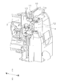
- FIG. 2 is a perspective view showing the internal structure of the wheel loader 1 below the cab 5.
- the wheel loader 1 includes a filter mounting body 10.
- the filter mounting body 10 is mounted on the rear frame 7. However, the filter mounting body 10 may be mounted on the vehicle body of the wheel loader 1.
- the vehicle body of the wheel loader 1 means a portion excluding the working machine 3 and each traveling wheel 4.
- the filter mounting body 10 may be covered with the outer plate of the wheel loader 1 or may be exposed to the outside of the wheel loader 1.
- the filter mounting body 10 has a bracket 11 and a filter device 12.
- the bracket 11 is attached to the rear frame 7.
- the bracket 11 is directly fixed to the rear frame 7 by a bolt 13.
- the mounting method of the bracket 11 is not limited to this.
- the filter device 12 is attached to the bracket 11.
- the filter device 12 is connected to a hydraulic oil pump (not shown) via a hydraulic pipe 14. The hydraulic pulsation when the hydraulic oil pump discharges the hydraulic oil is transmitted to the filter device 12.
- FIG. 3 is a side view showing the configuration of the filter mounting body 10.
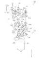
- FIG. 4 is an exploded perspective view showing the configuration of the filter mounting body 10.
- the filter mounting body 10 has three sets of mounting tools 15 in addition to the bracket 11 and the filter device 12 described above.
- Bracket 11 The bracket 11 has a first mounting plate 21, a second mounting plate 22, and an intermediate portion 23.
- the first mounting plate 21 is fixed to the rear frame 7 by the bolt 13.
- the first mounting plate 21 is formed in a flat plate shape.
- the first mounting plate 21 according to the present embodiment is arranged perpendicular to the horizontal direction, but is not limited to this.
- the shape and size of the first mounting plate 21 can be changed as appropriate.
- the second mounting plate 22 is an example of the "mounting plate” according to the present invention.
- the second mounting plate 22 is mounted on the filter device 12 via three sets of mounting tools 15.
- the second mounting plate 22 is formed in a flat plate shape.
- the second mounting plate 22 is arranged substantially perpendicular to the vertical direction.
- the second mounting plate 22 extends in a substantially horizontal direction. In the side view, the angle formed by the second mounting plate 22 with respect to the horizontal direction is preferably 5 degrees or less.
- the second mounting plate 22 is formed with four through holes 22a and three through holes 22b.
- the four through holes 22a are holes for inserting the four bolts 27 described later.
- the three through holes 22b are holes for mounting the three fixtures 15 described later.
- the shape and size of the second mounting plate 22 can be changed as appropriate.
- the intermediate portion 23 is connected to the first mounting plate 21 and the second mounting plate 22.
- the shape and size of the intermediate portion 23 can be changed as appropriate.
- the filter device 12 includes a filter case 24, a filter body 25, a plate 26, and four bolts 27.
- the filter case 24 has a case main body 24a, a first pipe connecting portion 24b, a second pipe connecting portion 24c, and four bosses 24d.
- the case body 24a is arranged on the filter body 25.
- An oil passage connected to the filter body 25 is formed inside the case body 24a.
- the first pipe connecting portion 24b is attached to the case body 24a.
- a hydraulic pipe (not shown) is connected to the first pipe connecting portion 24b.
- the second pipe connecting portion 24c is attached to the case body 24a.
- a hydraulic pipe 14 (see FIG. 2) is connected to the second pipe connecting portion 24c.
- the filter body 25 is a columnar shape extending in the vertical direction.
- the filter body 25 is arranged below the filter case 24.
- the filter body 25 is attached to the case body 24a.
- the filter body 25 is removable from the case body 24a. When the filtration function of the filter body 25 deteriorates, the filter body 25 can be replaced with a new filter body 25. As shown in FIG. 3, the center of gravity 12P of the filter device 12 is located in the filter main body 25.
- the plate 26 is a member for attaching three sets of fixtures 15 to the filter device 12.
- the plate 26 is arranged between the second mounting plate 22 of the bracket 11 and the filter case 24.
- the plate 26 is formed in a flat plate shape.
- the plate 26 is arranged substantially parallel to the second mounting plate 22 of the bracket 11. The shape and size of the plate 26 can be changed as appropriate.
- the plate 26 is formed with four through holes 26a and three through holes 26b. The three through holes 26b are located outside the four through holes 26a.
- the four bolts 27 are an example of the "plurality of second connecting members" according to the present invention.
- the four bolts 27 connect the plate 26 and the filter case 24.
- the four bolts 27 are inserted into the four through holes 26a of the plate 26 and fastened to the four bosses 24d of the filter case 24.
- four bolts 27 are used, but the number of bolts 27 can be changed as appropriate.
- FIG. 5 is a cross-sectional view showing the configuration of the fixture 15. As shown in FIG. 5, the fixture 15 has a bolt 30 and an elastic member 31.
- the bolt 30 is an example of the "first connecting member" according to the present invention.
- the bolt 30 connects the second mounting plate 22 of the bracket 11 and the plate 26 of the filter device 12 via the elastic member 31.
- the bolt 30 is inserted into the collar 32 and the through hole 26b of the plate 26.
- the head portion (upper end portion) of the bolt 30 is arranged on the elastic member 31 via the washer 33.
- the lower end of the bolt 30 is fastened to the nut 26c fixed to the lower surface of the plate 26.
- the elastic member 31 is formed in an annular shape or a tubular shape.
- the elastic member 31 is interposed between the bracket 11 and the filter device 12.
- the elastic member 31 not only suppresses the vibration of the filter device 12 from being transmitted to the bracket 11, but also suppresses the vibration of the filter device 12 itself.
- the elastic member 31 can be made of synthetic rubber such as chloroprene rubber, but is not limited thereto.
- the elastic member 31 includes a first elastic portion 31a, a second elastic portion 31b, and a collar 32.
- the first elastic portion 31a is arranged between the second mounting plate 22 and the plate 26.
- the washer 34 is arranged on the plate 26, the first elastic portion 31a is sandwiched between the second mounting plate 22 and the washer 34.
- the second elastic portion 31b is arranged between the second mounting plate 22 and the head of the bolt 30.
- the washer 33 is inserted between the head of the bolt 30 and the elastic portion 31, the second elastic portion 31b is sandwiched between the second mounting plate 22 and the washer 33.
- the elastic portion 31 since the elastic portion 31 is composed of the two elastic portions, the workability when assembling the fixture 15 can be improved.
- the elastic member 31 may include only one elastic portion, or may include three or more elastic portions.
- the collar 32 is inserted through the first elastic portion 31a, the second elastic portion 31b, and the second mounting plate 22.
- a bolt 30 is inserted inside the collar 32.
- the collar 32 is arranged between the plate 26 and the head of the bolt 30.
- the collar 32 is sandwiched between the washer 33 and the washer 34.
- the collar 32 prevents the entire elastic member 31 from being excessively crushed.
- the collar 32 can be made of a metal material such as steel, but is not limited to this.
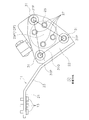
- FIG. 6 is a top view of the second mounting plate 22 as viewed from above.
- the figure 31Q is drawn by connecting the geometric centers 31P of each of the three elastic members 31 with a straight line.
- the figure 31Q drawn by connecting the geometric centers 31P of each of the three elastic members 31 with a straight line is a triangle.
- the geometric center 25P of the filter body 25 overlaps with the figure 31Q. Further, in the top view of the second mounting plate 22, each of the three elastic members 31 is located outside the filter main body 25. As a result, the vibration of the filter device 12 can be widely received within the range of the figure 31Q, so that even if the filter device 12 vibrates due to hydraulic pulsation, the vibration of the filter device 12 is efficiently transmitted to the bracket 11. Can be suppressed. Further, since the vibration of the filter device 12 can be widely received in the range of the figure 31Q, it is possible to suppress that a part of each elastic member 31 is compressed. Therefore, it is possible to efficiently suppress the vibration of the filter device 12.
- the center of gravity 12P (see FIG. 3) of the filter device 12 overlaps with the figure 31Q.
- the vibration of the filter device 12 can be suppressed more efficiently from being transmitted to the bracket 11, and the vibration of the filter device 12 can be suppressed more efficiently.
- a certain object "overlaps with the figure 31Q" is a concept including a case where the object is located inside the figure 31Q and a case where the object is located on the outer edge of the figure 31Q.
- the four bolts 27 are located inside the filter body 25. In this way, even if the four bolts 27 are arranged in a narrow range, the three elastic members 31 can be arranged widely apart by interposing the plate 26 as described above. Therefore, since the four bosses 24d can be compactly arranged in the filter case 24, the filter device 12 can be miniaturized.
- the filter mounting body 10 has three mounting tools 15, but the present invention is not limited to this.
- the filter mounting body 10 may have two or more mounting tools 15.
- a “straight line” is drawn as the figure 31Q. Is done.
- the filter mounting body 10 has five mounting tools 15, when the geometric centers 31P of each of the five elastic members 31 are connected by a straight line in the top view of the second mounting plate 22, a "pentagon” is drawn as a figure 31Q. Is done.
- the figure 31Q is drawn by connecting the geometric centers 31P of each of the three elastic members 31 with a straight line, but the present invention is not limited to this.
- the figure 31Q may be drawn by connecting the outermost edges of each of the three elastic members 31 with a straight line.
- each of the three elastic members 31 is located outside the filter body 25, but the present invention is not limited to this.
- at least one elastic member 31 among the three elastic members 31 may be located outside the filter body 25. Further, it is not necessary that all of the elastic members 31 are located outside the filter main body 25, and at least a part of the elastic members 31 may be located outside the filter main body 25.
- the filter device 12 has the plate 26, but the present invention is not limited to this.
- the filter case 24 is provided with the three bosses 24d so as to correspond to the positions of the three elastic members 31, the plate 26 may not be used.
- the fixture 15 has the collar 32, the washer 33, and the washer 34, but these are optional members.
- the wheel loader 1 has been described as an example of a work vehicle, but the filter mounting body 10 according to the present invention can be widely applied to other work vehicles such as a forklift.
- the filter mounting body 10 is connected to the hydraulic oil pump, but the present invention is not limited to this.
- the filter mounting body 10 is widely applicable to a pump that discharges a fluid. Therefore, the filter mounting body 10 can be applied not only to pumps that discharge liquids such as HST (Hydro-Static Transmission) hydraulic pumps, fuel pumps, urea water pumps, and water pumps, but also to pumps that discharge gas. ..
- HST Hydro-Static Transmission
Landscapes
- Chemical & Material Sciences (AREA)
- Engineering & Computer Science (AREA)
- Chemical Kinetics & Catalysis (AREA)
- General Engineering & Computer Science (AREA)
- Structural Engineering (AREA)
- Mechanical Engineering (AREA)
- Mining & Mineral Resources (AREA)
- Civil Engineering (AREA)
- Combustion & Propulsion (AREA)
- Vibration Prevention Devices (AREA)
- Details Of Reciprocating Pumps (AREA)
- Arrangement Of Transmissions (AREA)
- Filtration Of Liquid (AREA)
- Details And Applications Of Rotary Liquid Pumps (AREA)
- Cooling, Air Intake And Gas Exhaust, And Fuel Tank Arrangements In Propulsion Units (AREA)
- Motor Power Transmission Devices (AREA)
- Connection Of Plates (AREA)
Abstract
Priority Applications (3)
| Application Number | Priority Date | Filing Date | Title |
|---|---|---|---|
| CN202080012627.2A CN113412142B (zh) | 2019-03-19 | 2020-03-17 | 过滤器安装体以及作业车辆 |
| US17/426,911 US12239926B2 (en) | 2019-03-19 | 2020-03-17 | Filter attachment body and work vehicle |
| EP20773790.9A EP3906989B1 (fr) | 2019-03-19 | 2020-03-17 | Élément de fixation de filtre et véhicule de travail |
Applications Claiming Priority (2)
| Application Number | Priority Date | Filing Date | Title |
|---|---|---|---|
| JP2019051088A JP7355510B2 (ja) | 2019-03-19 | 2019-03-19 | フィルタ取付け体、および作業車両 |
| JP2019-051088 | 2019-03-19 |
Publications (1)
| Publication Number | Publication Date |
|---|---|
| WO2020189680A1 true WO2020189680A1 (fr) | 2020-09-24 |
Family
ID=72520125
Family Applications (1)
| Application Number | Title | Priority Date | Filing Date |
|---|---|---|---|
| PCT/JP2020/011729 Ceased WO2020189680A1 (fr) | 2019-03-19 | 2020-03-17 | Élément de fixation de filtre et véhicule de travail |
Country Status (5)
| Country | Link |
|---|---|
| US (1) | US12239926B2 (fr) |
| EP (1) | EP3906989B1 (fr) |
| JP (1) | JP7355510B2 (fr) |
| CN (1) | CN113412142B (fr) |
| WO (1) | WO2020189680A1 (fr) |
Citations (5)
| Publication number | Priority date | Publication date | Assignee | Title |
|---|---|---|---|---|
| JPS56110820U (fr) * | 1980-01-29 | 1981-08-27 | ||
| JPS5719215U (fr) * | 1980-07-08 | 1982-02-01 | ||
| JP2000087945A (ja) * | 1998-09-11 | 2000-03-28 | Sanwa Packing Kogyo Co Ltd | 組合せ部品及びその製造方法 |
| JP2006188118A (ja) | 2005-01-05 | 2006-07-20 | Shin Caterpillar Mitsubishi Ltd | 作業車のhstチャージ回路のオイルフィルタ |
| JP2018053811A (ja) * | 2016-09-29 | 2018-04-05 | 株式会社クボタ | 作業機 |
Family Cites Families (3)
| Publication number | Priority date | Publication date | Assignee | Title |
|---|---|---|---|---|
| JP2013210079A (ja) | 2012-03-30 | 2013-10-10 | Hitachi Automotive Systems Ltd | 締結部材及びコンプレッサ装置 |
| JP6008751B2 (ja) | 2013-02-04 | 2016-10-19 | 小島プレス工業株式会社 | 車両部品の取付具 |
| CN206738318U (zh) | 2017-01-23 | 2017-12-12 | 华南建材(深圳)有限公司 | 一种船用壁板弹性连接件 |
-
2019
- 2019-03-19 JP JP2019051088A patent/JP7355510B2/ja active Active
-
2020
- 2020-03-17 EP EP20773790.9A patent/EP3906989B1/fr active Active
- 2020-03-17 US US17/426,911 patent/US12239926B2/en active Active
- 2020-03-17 WO PCT/JP2020/011729 patent/WO2020189680A1/fr not_active Ceased
- 2020-03-17 CN CN202080012627.2A patent/CN113412142B/zh active Active
Patent Citations (5)
| Publication number | Priority date | Publication date | Assignee | Title |
|---|---|---|---|---|
| JPS56110820U (fr) * | 1980-01-29 | 1981-08-27 | ||
| JPS5719215U (fr) * | 1980-07-08 | 1982-02-01 | ||
| JP2000087945A (ja) * | 1998-09-11 | 2000-03-28 | Sanwa Packing Kogyo Co Ltd | 組合せ部品及びその製造方法 |
| JP2006188118A (ja) | 2005-01-05 | 2006-07-20 | Shin Caterpillar Mitsubishi Ltd | 作業車のhstチャージ回路のオイルフィルタ |
| JP2018053811A (ja) * | 2016-09-29 | 2018-04-05 | 株式会社クボタ | 作業機 |
Also Published As
| Publication number | Publication date |
|---|---|
| CN113412142A (zh) | 2021-09-17 |
| EP3906989B1 (fr) | 2025-08-06 |
| JP7355510B2 (ja) | 2023-10-03 |
| EP3906989A1 (fr) | 2021-11-10 |
| US20220096973A1 (en) | 2022-03-31 |
| JP2020152182A (ja) | 2020-09-24 |
| US12239926B2 (en) | 2025-03-04 |
| CN113412142B (zh) | 2022-09-13 |
| EP3906989A4 (fr) | 2022-08-31 |
Similar Documents
| Publication | Publication Date | Title |
|---|---|---|
| JP4705130B2 (ja) | 建設機械 | |
| US9238901B2 (en) | Supporting mechanism, exhaust treatment unit, and wheel loader | |
| US9441527B2 (en) | Supporting mechanism, exhaust treatment unit, and wheel loader | |
| US20090121521A1 (en) | Frame Structure for Working Vehicle | |
| JP3782004B2 (ja) | フロントローダとバックホーを装着できるトラクタ | |
| US7874390B2 (en) | Working machine | |
| JPH04316405A (ja) | トラクタの作業機取り付け構造体 | |
| CN104334806B (zh) | 作业车辆 | |
| US10024026B2 (en) | Front loader frame, front loader equipped with front loader frame, and work vehicle equipped with front loader | |
| CN105829197B (zh) | 拖拉机 | |
| JP7355510B2 (ja) | フィルタ取付け体、および作業車両 | |
| JP6415916B2 (ja) | 建設機械 | |
| JP5993830B2 (ja) | 建設機械 | |
| JP4569577B2 (ja) | 建設機械の配管接続構造 | |
| JP3947024B2 (ja) | ローダ作業機 | |
| JP2003276653A (ja) | トラクタのフロントガード装置 | |
| CN204755479U (zh) | 一种油路清洁装置 | |
| JP2003278179A (ja) | ブーム枢支部の補強構造 | |
| JP2006188118A (ja) | 作業車のhstチャージ回路のオイルフィルタ | |
| JP6908567B2 (ja) | 建設機械 | |
| JP3489980B2 (ja) | 産業用車両 | |
| JP2013104249A (ja) | 作業機械の油圧脈動低減装置 | |
| JP2024118909A (ja) | 建設機械の旋回フレーム | |
| JP2005076686A (ja) | 走行車両の油圧ポンプ取付装置 | |
| JP2000291055A (ja) | 旋回式建設機械 |
Legal Events
| Date | Code | Title | Description |
|---|---|---|---|
| 121 | Ep: the epo has been informed by wipo that ep was designated in this application |
Ref document number: 20773790 Country of ref document: EP Kind code of ref document: A1 |
|
| ENP | Entry into the national phase |
Ref document number: 2020773790 Country of ref document: EP Effective date: 20210804 |
|
| NENP | Non-entry into the national phase |
Ref country code: DE |
|
| WWG | Wipo information: grant in national office |
Ref document number: 17426911 Country of ref document: US |
|
| WWG | Wipo information: grant in national office |
Ref document number: 2020773790 Country of ref document: EP |