WO2020194439A1 - Groupe d'électrodes, batterie et bloc-batterie - Google Patents
Groupe d'électrodes, batterie et bloc-batterie Download PDFInfo
- Publication number
- WO2020194439A1 WO2020194439A1 PCT/JP2019/012453 JP2019012453W WO2020194439A1 WO 2020194439 A1 WO2020194439 A1 WO 2020194439A1 JP 2019012453 W JP2019012453 W JP 2019012453W WO 2020194439 A1 WO2020194439 A1 WO 2020194439A1
- Authority
- WO
- WIPO (PCT)
- Prior art keywords
- negative electrode
- active material
- positive electrode
- battery
- containing layer
- Prior art date
- Legal status (The legal status is an assumption and is not a legal conclusion. Google has not performed a legal analysis and makes no representation as to the accuracy of the status listed.)
- Ceased
Links
Images






Classifications
-
- H—ELECTRICITY
- H01—ELECTRIC ELEMENTS
- H01M—PROCESSES OR MEANS, e.g. BATTERIES, FOR THE DIRECT CONVERSION OF CHEMICAL ENERGY INTO ELECTRICAL ENERGY
- H01M10/00—Secondary cells; Manufacture thereof
- H01M10/05—Accumulators with non-aqueous electrolyte
- H01M10/052—Li-accumulators
- H01M10/0525—Rocking-chair batteries, i.e. batteries with lithium insertion or intercalation in both electrodes; Lithium-ion batteries
-
- H—ELECTRICITY
- H01—ELECTRIC ELEMENTS
- H01M—PROCESSES OR MEANS, e.g. BATTERIES, FOR THE DIRECT CONVERSION OF CHEMICAL ENERGY INTO ELECTRICAL ENERGY
- H01M10/00—Secondary cells; Manufacture thereof
- H01M10/04—Construction or manufacture in general
- H01M10/0431—Cells with wound or folded electrodes
-
- H—ELECTRICITY
- H01—ELECTRIC ELEMENTS
- H01M—PROCESSES OR MEANS, e.g. BATTERIES, FOR THE DIRECT CONVERSION OF CHEMICAL ENERGY INTO ELECTRICAL ENERGY
- H01M10/00—Secondary cells; Manufacture thereof
- H01M10/05—Accumulators with non-aqueous electrolyte
- H01M10/056—Accumulators with non-aqueous electrolyte characterised by the materials used as electrolytes, e.g. mixed inorganic/organic electrolytes
- H01M10/0564—Accumulators with non-aqueous electrolyte characterised by the materials used as electrolytes, e.g. mixed inorganic/organic electrolytes the electrolyte being constituted of organic materials only
-
- H—ELECTRICITY
- H01—ELECTRIC ELEMENTS
- H01M—PROCESSES OR MEANS, e.g. BATTERIES, FOR THE DIRECT CONVERSION OF CHEMICAL ENERGY INTO ELECTRICAL ENERGY
- H01M10/00—Secondary cells; Manufacture thereof
- H01M10/05—Accumulators with non-aqueous electrolyte
- H01M10/056—Accumulators with non-aqueous electrolyte characterised by the materials used as electrolytes, e.g. mixed inorganic/organic electrolytes
- H01M10/0564—Accumulators with non-aqueous electrolyte characterised by the materials used as electrolytes, e.g. mixed inorganic/organic electrolytes the electrolyte being constituted of organic materials only
- H01M10/0566—Liquid materials
- H01M10/0567—Liquid materials characterised by the additives
-
- H—ELECTRICITY
- H01—ELECTRIC ELEMENTS
- H01M—PROCESSES OR MEANS, e.g. BATTERIES, FOR THE DIRECT CONVERSION OF CHEMICAL ENERGY INTO ELECTRICAL ENERGY
- H01M10/00—Secondary cells; Manufacture thereof
- H01M10/05—Accumulators with non-aqueous electrolyte
- H01M10/058—Construction or manufacture
- H01M10/0587—Construction or manufacture of accumulators having only wound construction elements, i.e. wound positive electrodes, wound negative electrodes and wound separators
-
- H—ELECTRICITY
- H01—ELECTRIC ELEMENTS
- H01M—PROCESSES OR MEANS, e.g. BATTERIES, FOR THE DIRECT CONVERSION OF CHEMICAL ENERGY INTO ELECTRICAL ENERGY
- H01M4/00—Electrodes
- H01M4/02—Electrodes composed of, or comprising, active material
- H01M4/36—Selection of substances as active materials, active masses, active liquids
- H01M4/48—Selection of substances as active materials, active masses, active liquids of inorganic oxides or hydroxides
- H01M4/485—Selection of substances as active materials, active masses, active liquids of inorganic oxides or hydroxides of mixed oxides or hydroxides for inserting or intercalating light metals, e.g. LiTi2O4 or LiTi2OxFy
-
- H—ELECTRICITY
- H01—ELECTRIC ELEMENTS
- H01M—PROCESSES OR MEANS, e.g. BATTERIES, FOR THE DIRECT CONVERSION OF CHEMICAL ENERGY INTO ELECTRICAL ENERGY
- H01M4/00—Electrodes
- H01M4/02—Electrodes composed of, or comprising, active material
- H01M4/36—Selection of substances as active materials, active masses, active liquids
- H01M4/48—Selection of substances as active materials, active masses, active liquids of inorganic oxides or hydroxides
- H01M4/50—Selection of substances as active materials, active masses, active liquids of inorganic oxides or hydroxides of manganese
- H01M4/505—Selection of substances as active materials, active masses, active liquids of inorganic oxides or hydroxides of manganese of mixed oxides or hydroxides containing manganese for inserting or intercalating light metals, e.g. LiMn2O4 or LiMn2OxFy
-
- H—ELECTRICITY
- H01—ELECTRIC ELEMENTS
- H01M—PROCESSES OR MEANS, e.g. BATTERIES, FOR THE DIRECT CONVERSION OF CHEMICAL ENERGY INTO ELECTRICAL ENERGY
- H01M4/00—Electrodes
- H01M4/02—Electrodes composed of, or comprising, active material
- H01M4/36—Selection of substances as active materials, active masses, active liquids
- H01M4/48—Selection of substances as active materials, active masses, active liquids of inorganic oxides or hydroxides
- H01M4/52—Selection of substances as active materials, active masses, active liquids of inorganic oxides or hydroxides of nickel, cobalt or iron
- H01M4/525—Selection of substances as active materials, active masses, active liquids of inorganic oxides or hydroxides of nickel, cobalt or iron of mixed oxides or hydroxides containing iron, cobalt or nickel for inserting or intercalating light metals, e.g. LiNiO2, LiCoO2 or LiCoOxFy
-
- H—ELECTRICITY
- H01—ELECTRIC ELEMENTS
- H01M—PROCESSES OR MEANS, e.g. BATTERIES, FOR THE DIRECT CONVERSION OF CHEMICAL ENERGY INTO ELECTRICAL ENERGY
- H01M2300/00—Electrolytes
- H01M2300/0017—Non-aqueous electrolytes
- H01M2300/0025—Organic electrolyte
-
- Y—GENERAL TAGGING OF NEW TECHNOLOGICAL DEVELOPMENTS; GENERAL TAGGING OF CROSS-SECTIONAL TECHNOLOGIES SPANNING OVER SEVERAL SECTIONS OF THE IPC; TECHNICAL SUBJECTS COVERED BY FORMER USPC CROSS-REFERENCE ART COLLECTIONS [XRACs] AND DIGESTS
- Y02—TECHNOLOGIES OR APPLICATIONS FOR MITIGATION OR ADAPTATION AGAINST CLIMATE CHANGE
- Y02E—REDUCTION OF GREENHOUSE GAS [GHG] EMISSIONS, RELATED TO ENERGY GENERATION, TRANSMISSION OR DISTRIBUTION
- Y02E60/00—Enabling technologies; Technologies with a potential or indirect contribution to GHG emissions mitigation
- Y02E60/10—Energy storage using batteries
-
- Y—GENERAL TAGGING OF NEW TECHNOLOGICAL DEVELOPMENTS; GENERAL TAGGING OF CROSS-SECTIONAL TECHNOLOGIES SPANNING OVER SEVERAL SECTIONS OF THE IPC; TECHNICAL SUBJECTS COVERED BY FORMER USPC CROSS-REFERENCE ART COLLECTIONS [XRACs] AND DIGESTS
- Y02—TECHNOLOGIES OR APPLICATIONS FOR MITIGATION OR ADAPTATION AGAINST CLIMATE CHANGE
- Y02P—CLIMATE CHANGE MITIGATION TECHNOLOGIES IN THE PRODUCTION OR PROCESSING OF GOODS
- Y02P70/00—Climate change mitigation technologies in the production process for final industrial or consumer products
- Y02P70/50—Manufacturing or production processes characterised by the final manufactured product
Definitions
- Embodiments of the present invention relate to electrode groups, batteries, and battery packs.
- Secondary batteries such as non-aqueous electrolyte batteries, including lithium ion secondary batteries, are widely used in mobile devices, automobiles, storage batteries, and the like.
- Lithium-ion secondary batteries and the like are power storage devices whose market scale is expected to expand, but capacity deterioration when the charge / discharge cycle is repeated has become an issue.
- Various factors such as deterioration of active material, gas generation, imbalance, etc. can be mentioned as factors of capacity deterioration.
- Balance deviation which is one of the above factors, is a phenomenon in which the range of use shifts between the positive electrode and the negative electrode as the charge / discharge cycle is repeated. If this phenomenon can be suppressed, it is expected that a decrease in the capacity of the secondary battery can be suppressed. It is considered that one of the causes of the imbalance is that the self-discharge of the negative electrode causes a difference in the charging state between the positive electrode and the negative electrode.
- an electrode group including a laminate including a positive electrode and a negative electrode is provided.
- the positive electrode includes a positive electrode current collector and a positive electrode active material-containing layer on the positive electrode current collector.
- the negative electrode includes a negative electrode current collector and a negative electrode active material-containing layer above the negative electrode current collector.
- the first width of the positive electrode active material-containing layer in the first direction is narrower than the second width of the negative electrode active material-containing layer in the first direction.
- the electrode group has a winding structure in which the laminated body is wound so that the center is located along the first direction.
- the length L which corresponds to the difference between the second width and the first width, is expressed in mm, and the length L, which is expressed in g / m 2 of the negative electrode active material-containing layer per unit area of each side of the negative electrode current collector.
- a basis weight M a that, the ratio p / n of the capacity p of the positive electrode to volume n of the negative electrode satisfy the relation of 40 mg / m ⁇ (L ⁇ M a) / (p / n) ⁇ 60 mg / m.
- a battery including the electrode group according to the above embodiment is provided.
- a battery pack including the battery according to the above embodiment is provided.
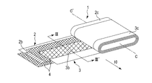
- FIG. 1 is a perspective view schematically showing an example electrode group according to the embodiment.
- FIG. 2 is a perspective view schematically showing a state in which the electrode group is partially expanded.
- FIG. 3 is a cross-sectional view of the electrode group shown in FIG. 2 along the line III-III'.
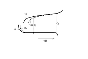
- FIG. 4 is a graph schematically showing a potential curve at the time of initial charge / discharge of an example battery using the electrode group according to the embodiment.
- FIG. 5 is a graph schematically showing a potential curve in a shipped state of an example battery using the electrode group according to the embodiment.
- FIG. 6 is a conceptual diagram showing an initial charging state of an example battery using the electrode group according to the embodiment.
- FIG. 7 is a conceptual diagram showing initial adjustment in an example battery using the electrode group according to the embodiment.
- FIG. 1 is a perspective view schematically showing an example electrode group according to the embodiment.
- FIG. 2 is a perspective view schematically showing a state in which the electrode group is partially expanded.
- FIG. 3 is
- FIG. 8 is a conceptual diagram showing additional charging after adjusting the battery of an example using the electrode group according to the embodiment to the shipping state.
- FIG. 9 is a conceptual diagram showing an example of imbalance.
- FIG. 10 is a conceptual diagram showing additional charging after the imbalance of the example of FIG. 9 occurs.
- FIG. 11 is a partially cutaway perspective view of the battery of the first example according to the embodiment.
- FIG. 12 is an enlarged cross-sectional view of part A of the battery shown in FIG.
- FIG. 13 is a partially cutaway perspective view of the battery of the second example according to the embodiment.
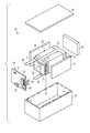
- FIG. 14 is an exploded perspective view schematically showing an example of the battery pack according to the embodiment.
- FIG. 15 is a block diagram showing an example of the electric circuit of the battery pack shown in FIG.
- each figure is a schematic view for facilitating the explanation of the embodiment and its understanding, and the shape, dimensions, ratio, etc. of the figure may differ from those of the actual device. However, these are described below and known techniques. The design can be changed as appropriate by taking into consideration.
- an electrode group including a laminated body includes a positive electrode and a negative electrode.
- the positive electrode includes a positive electrode current collector and a positive electrode active material-containing layer on the positive electrode current collector.
- the negative electrode includes a negative electrode current collector and a negative electrode active material-containing layer above the negative electrode current collector.
- the first width of the positive electrode active material-containing layer in the first direction is narrower than the second width of the negative electrode active material-containing layer in the first direction.
- the electrode group has a winding structure.
- the winding type structure is formed by winding the laminate so that the center is located along the first direction.
- a length L corresponding to the difference between the second width and the first width, the ratio of the basis weight M a and capacity p of the positive electrode to volume n of the negative electrode of the negative electrode active material-containing layer per one surface of the negative electrode current collector p / the n, satisfies the relationship of 40 mg / m ⁇ (L ⁇ M a) / (p / n) ⁇ 60 mg / m.
- the battery using the electrode group having the above configuration In the battery using the electrode group having the above configuration, the capacity decrease when the charge / discharge cycle is repeated is suppressed. Therefore, the battery using the electrode group has an excellent capacity retention rate.
- the positive electrode includes a positive electrode current collector and a positive electrode active material-containing layer formed on the positive electrode current collector.
- the positive electrode current collector can include a portion where the positive electrode active material-containing layer is not supported on the surface. This portion can serve as a positive electrode current collector tab. Alternatively, the positive electrode may further include a positive electrode current collector tab that is separate from the positive electrode current collector.
- the positive electrode active material-containing layer contains the positive electrode active material.
- the positive electrode active material-containing layer can further contain a conductive agent and a binder, if necessary.
- the negative electrode includes a negative electrode current collector and a negative electrode active material-containing layer formed on the negative electrode current collector.
- the negative electrode current collector can include a portion where the negative electrode active material-containing layer is not supported on the surface. This portion can serve as a negative electrode current collector tab. Alternatively, the negative electrode may further include a negative electrode current collector tab that is separate from the negative electrode current collector.
- the negative electrode active material-containing layer contains the negative electrode active material.
- the negative electrode active material-containing layer can further contain a conductive agent and a binder, if necessary.
- the electrode group according to the embodiment may further include a separator.
- the separator may form an electrode group together with the positive electrode and the negative electrode.
- the positive electrode active material-containing layer and the negative electrode active material-containing layer can face each other via a separator.
- the electrode group has a winding type structure.
- the electrode group according to the embodiment will be described with reference to FIGS. 1 to 3.
- FIG. 1 is a perspective view schematically showing an example electrode group according to the embodiment.
- FIG. 2 is a perspective view schematically showing a state in which the electrode group is partially expanded.
- FIG. 3 is a cross-sectional view of the electrode group shown in FIG. 2 along the line III-III'.
- the electrode group 1 shown in FIGS. 1 to 3 includes a positive electrode 3, a negative electrode 2, and a separator 4.
- the electrode group 1 has a structure in which a laminate including a positive electrode 3, a negative electrode 2, and a separator 4 arranged between the positive electrode 3 and the negative electrode 2 is wound into a flat shape.
- the laminated body is wound around a virtual line CC'parallel to the first direction 10 intersecting the first edge along the long side of the positive electrode 3.
- the positive electrode 3 includes a positive electrode current collector 3a, a positive electrode active material-containing layer 3b, and a positive electrode current collector tab 3c.
- the positive electrode current collector 3a has a band-like shape.
- the positive electrode active material-containing layer 3b is supported on the positive electrode current collector 3a.
- the positive electrode current collector tab 3c is provided at one side of the positive electrode current collector 3a, for example, at an end parallel to the long side of the strip shape.
- the positive electrode current collector tab 3c can be a part of the positive electrode current collector 3a.
- the portion of the positive electrode current collector 3a in which the positive electrode active material-containing layer 3b is not supported can be used as the positive electrode current collector tab 3c.
- the positive electrode current collecting tab 3c may protrude from the end of the positive electrode active material-containing layer 3b.
- the negative electrode 2 includes a negative electrode current collector 2a and a negative electrode active material-containing layer 2b.
- the negative electrode current collector 2a has a band-like shape.
- the negative electrode active material-containing layer 2b is supported on the negative electrode current collector 2a.
- the negative electrode current collector tab 2c is provided at one side of the negative electrode current collector 2a, for example, at an end parallel to the long side of the strip shape.
- the negative electrode current collector tab 2c can be a part of the negative electrode current collector 2a.
- the portion of the negative electrode current collector 2a in which the negative electrode active material-containing layer 2b is not supported can be used as the negative electrode current collector tab 2c.
- the negative electrode current collecting tab 2c can protrude from the end of the negative electrode active material-containing layer 2b.
- the positive electrode lead 16a and the negative electrode lead 15a can be connected to the electrode group 1, or the insulating sheet 8 can be provided in the electrode group 1.
- the positive electrode lead 16a is electrically connected to the positive electrode current collecting tab 3c.
- the negative electrode lead 15a is electrically connected to the negative electrode current collecting tab 2c.
- the insulating sheet 8 covers, for example, the outermost periphery of the electrode group 1 except for the positive electrode current collecting tab 3c and the negative electrode current collecting tab 2c.
- the positive electrode active material-containing layer 3b of the positive electrode 3 and the negative electrode active material-containing layer 2b of the negative electrode 2 face each other via the separator 4.
- a positive electrode current collecting tab 3c protrudes from the negative electrode active material-containing layer 2b and the separator 4 on one side along the virtual line CC'which corresponds to the winding axis of the laminated body. Further, the negative electrode current collecting tab 2c protrudes to the opposite side from the positive electrode active material-containing layer 3b and the separator 4. Therefore, in the electrode group 1, the positive electrode current collecting tab 3c wound in a flat spiral shape is located on the first end surface intersecting the virtual line CC'.
- the negative electrode current collecting tab 2c wound in a flat spiral shape is located on the second end surface intersecting the virtual line CC'on the opposite side of the electrode group 1.
- the first end surface and the second end surface can be parallel to the first edge portion of the positive electrode 3.
- the positive electrode current collecting tab 3c is located on the opposite side of the laminated body wound from the negative electrode current collecting tab 2c.
- the positive electrode current collecting tab 3c and the negative electrode current collecting tab 2c may be arranged on the same end face in the wound laminate.
- the first width W P of the positive electrode active material-containing layer 3b, the second smaller width W N of the negative electrode active material-containing layer 2b As shown in FIG. 3, the first width W P of the positive electrode active material-containing layer 3b, the second smaller width W N of the negative electrode active material-containing layer 2b.
- the second width W N which is the width of the over the anode active material-containing layer 2b in the first direction 10.
- the first width W P of the positive electrode active material-containing layer 3b is narrower than the second width W N of the negative electrode active material-containing layer 2b. Therefore, the entire region of the positive electrode active material-containing layer 3b along the first direction overlaps with the negative electrode active material-containing layer 2b. Second width W N of the negative electrode active material-containing layer 2b is wider than the first width W P of the positive electrode active material-containing layer 3b. Therefore, a part of the negative electrode active material-containing layer 2b protrudes outward in the width direction from the end portion of the positive electrode active material-containing layer 3b.
- a part of the negative electrode active material-containing layer 2b along the first direction overlaps with the positive electrode active material-containing layer 3b, and the other region does not overlap with the positive electrode active material-containing layer 3b.
- the regions of the negative electrode active material-containing layer 2b that do not overlap with the positive electrode active material-containing layer 3b can be arranged at both ends in the width direction with a region overlapping with the positive electrode active material-containing layer 3b in between.
- the negative electrode active material-containing layer 2b protrudes beyond the positive electrode active material-containing layer 3b in both directions parallel to the winding axis in the electrode group 1 (both directions along the first direction 10).
- the positive electrode active material-containing layer 3b is opposed to the anode active material-containing layer 2b with the separator 4 throughout the first width W P.
- the negative electrode active material-containing layer 2b includes a portion facing the positive electrode active material-containing layer 3b via the separator 4 and a portion not facing the positive electrode active material-containing layer 3b.
- the negative electrode active material-containing layer 2b includes an opposing portion 2d corresponding to a portion facing the positive electrode active material-containing layer 3b in the intermediate portion along the first direction 10. That is, the facing portion 2d is a region of the negative electrode active material-containing layer 2b that overlaps the positive electrode active material-containing layer 3b in the plane direction.
- the anode active material-containing layer 2b has a first non-facing portion 2e 1 corresponding to one at the end not facing the positive electrode active material-containing layer 3b part of the second width W N, the second width W N
- the other end includes a second non-opposing portion 2e 2 corresponding to a portion not facing the positive electrode active material-containing layer 3b.
- the first non-opposing portion 2e 1 and the second non-opposing portion 2e 2 correspond to portions of the negative electrode active material-containing layer 2b that protrude outward in the width direction from the end portion of the positive electrode active material-containing layer 3b. That is, these non-opposing portions are regions of the negative electrode active material-containing layer 2b that do not overlap with the positive electrode active material-containing layer 3b in the plane direction.
- both the length L1 of the first non-opposing portion 2e 1 extending in the first direction 10 and the length L2 of the second non-opposing portion 2e 2 extending in the first direction 10 exceed zero. That is, as shown in FIG. 3, it is desirable that the negative electrode active material-containing layer 2b extends to the outside of the positive electrode active material-containing layer 3b on both sides in the width direction.
- a first non-facing portion 2e 1 from protruding length L1 plus the second non-facing portions 2e 2 from protruding length L2, the second width W N and the positive electrode active material-containing layer 3b of the negative electrode active material-containing layer 2b equal to the difference between the first width W P.
- the electrode group according to the embodiment satisfies the relationship of the following formula (1): 40 mg / m ⁇ (L ⁇ M a) / (p / n) ⁇ 60 mg / m (1).
- L, symbol M a, and p / n each represent one of the following.
- the length L is expressed in numerical units of, for example, mm (millimeter).
- the length L can be, for example, 0.5 mm or more, preferably 1 mm or more.
- the length L can be, for example, 3 mm or less, preferably 2.5 mm or less.
- the non-opposing portion of the negative electrode hardly contributes to charging / discharging. Since the length L of the non-opposing portion of the negative electrode is not too long, the energy density can be secured.
- Symbol M a represents the weight per unit area of the negative electrode active material-containing layer per unit area.
- Basis weight M a of the negative electrode active material-containing layer is referred to in per side of the main surface of the anode current collector refers to the mass per unit area of the negative electrode active material-containing layer is carried.
- the negative electrode active material-containing layer may be provided on only one of the main surfaces of the negative electrode current collector. Alternatively, the negative electrode active material-containing layer may be provided on both main surfaces on the front and back surfaces of the negative electrode current collector. When the negative electrode active material-containing layers are formed on both sides of the negative electrode current collector, the mass per unit area of the negative electrode active material supported on one surface of the negative electrode current collector and the other of the negative electrode current collectors.
- the mean value of the mass per unit area of the negative electrode active material-containing layer which is carried on the surface is equal to the basis weight M a of the negative electrode active material-containing layer.
- the mass per hit can be equal.
- the basis weight M a of the negative electrode active material-containing layer, and the mass per unit area of the opposed portion to the positive electrode active material-containing layer, the non-facing portions for the positive electrode active material-containing layer include both with mass per unit area.
- Basis weight M a of the negative electrode active material-containing layer is, for example, quantify units of g / m 2 (grams / square meter). Basis weight M a of the negative electrode active material-containing layer may be, for example, 30 g / m 2 or more. Basis weight M a of the negative electrode active material-containing layer may be, for example, 100 g / m 2 or less.
- the molecule (numerator) in the above formula (1) (L ⁇ Ma) is a portion of the negative electrode active material-containing layer that exists as a non-opposing portion (comprehensive of the first non-opposing portion and the second non-opposing portion). Represents the amount of.
- the symbol p / n represents the positive / negative electrode capacity ratio for the electrode group.
- the positive electrode capacity p and the negative electrode capacity n are represented, for example, in numerical units of mAh (milliampere-hour).
- the ratio p / n can be, for example, greater than 1, preferably 1.1 or greater.
- the ratio p / n can be, for example, 1.8 or less, preferably 1.6 or less.
- (L ⁇ M a) / is the value of (p / n) is less than 40 mg / m or more 60 mg / m, the following effects can be obtained.
- Lithium ions charged in the negative electrode during the initial (early) charging of the battery using the electrode group diffuse to the non-opposed portions (first non-opposed portion and second non-opposed portion) of the negative electrode active material-containing layer.
- the diffused lithium ions are immobilized on the non-opposing portion of the negative electrode active material-containing layer. In such a state, it is suppressed that lithium ions are further drifted to the non-opposing portion at the time of additional charging. Therefore, the self-discharge of the negative electrode can be reduced, and the balance deviation can be reduced each time charging and discharging are repeated. Therefore, it is possible to suppress a decrease in capacity due to imbalance.
- non-facing portion of the negative electrode active material-containing layer is meant that relatively small with respect to the facing portion. In this case, even if lithium ions diffuse in the non-opposing portion, it is difficult to fix them there. This is because even the non-opposing portion behaves similarly to the facing portion at the time of recharging, and it can be expressed that the boundary between the non-opposing portion and the facing portion is not clear.
- the ratio p / n is too large, the basis weight of the negative electrode active material-containing layer with respect to the positive electrode capacity p is small, and lithium easily moves from the negative electrode to the positive electrode, so that self-discharge tends to proceed. Therefore, it is difficult for lithium ions to be immobilized on the non-opposing portion of the negative electrode active material-containing layer. As a result of difficulty in immobilizing lithium ions in the non-opposed portion, it is not possible to suppress the imbalance when the charge / discharge cycle is repeated, and the capacity is reduced.
- FIG. 4 is a graph schematically showing a potential curve at the time of initial charge / discharge of an example battery using the electrode group according to the embodiment.
- FIG. 5 is a graph schematically showing a potential curve in a shipped state of an example battery using the electrode group according to the embodiment.
- the horizontal axis indicates the capacity of the positive electrode and the negative electrode of the battery.
- the capacity C C indicates the charge capacity of the positive electrode
- the capacity D C indicates the discharge capacity of the positive electrode
- Capacity C A indicates the charge capacity of the negative electrode
- capacity D A indicates the discharge capacity of the negative electrode.
- Curve 13 for example, to measure the discharge capacity D C of the positive electrode, the oxidation of lithium - positive potential with respect to the reduction potential (unit: V (vs. Li / Li + )) , and is plotted against volume.
- Curve 12 for example, to measure the discharge capacity D A of the negative electrode, the oxidation of the lithium - negative potential with respect to the reduction potential (unit: V (vs. Li / Li + )) is plotted against the capacity.
- Curve 14 schematically shows the battery voltage (unit: V) as a function of the capacity of the battery in this example.
- the positional relationship between the curve 13 and the curve 12 at the time of the first charge / discharge is arranged as shown in FIG. 4 due to the difference in the charge / discharge efficiency of the positive and negative electrodes at the time of the first charge / discharge. It has become. That is, the lateral position of the positive electrode potential curve (curve 13) is biased toward the charging side (right side in FIG. 4) as compared with the negative electrode potential curve (curve 12). Therefore, the portion of the negative electrode potential curve (curve 12) that does not overlap with the positive electrode potential curve (curve 13) is on the discharge side (left side of FIG. 4).
- the discharge capacity D C of the positive electrode is smaller than the discharge capacity D A of the negative electrode.
- the width of the portion of the negative electrode potential curve (curve 12) that does not overlap with the positive electrode potential curve (curve 13) corresponds to the difference (D A- D C ) between the positive electrode discharge capacity D C and the negative electrode discharge capacity D A. To do.
- lithium ions move from the positive electrode to the opposite portion of the negative electrode. After that, a part of lithium ions diffuses from the facing portion to the non-opposing portion of the negative electrode. Lithium ions diffused to the non-opposing portion are immobilized there. As a result, the discharge capacity D A of the negative electrode is reduced. On the other hand, the change in the discharge capacity D C of the positive electrode is small. As a result, as shown in FIG. 5, the difference (D A- D C ) between the discharge capacity D C of the positive electrode and the discharge capacity D A of the negative electrode is reduced.
- the distribution of lithium ions in the negative electrode is adjusted when the battery is first charged, and the charged state of the positive electrode and the charged state of the negative electrode are brought close to each other.
- the positive electrode potential curve (curve 13) and the negative electrode potential curve (curve 12) substantially overlap each other in the lateral direction.
- the charge states of the positive electrode and the negative electrode match in the shipping state as in the example battery shown in FIG. Since lithium is immobilized on the non-opposing portion of the negative electrode, self-discharge of the negative electrode is suppressed, so that the matching of the charging states between the positive electrode and the negative electrode can be maintained.
- the balance between the charged state of the positive electrode and the charged state of the negative electrode can be better controlled. For example, when the battery is charged to a low charge state (SOC; State Of Charge), the decrease rate of the charge state of the negative electrode exceeds the decrease rate of the charge state of the positive electrode.
- SOC State Of Charge
- FIG. 6-8 will be used to explain the transition of the relationship between the charged state of the positive electrode and the charged state of the negative electrode in the initial adjustment for adjusting the assembled battery to the shipping state.
- FIG. 6 is a conceptual diagram showing an initial charging state of an example battery using the electrode group according to the embodiment.
- FIG. 7 is a conceptual diagram showing initial adjustment in an example battery using the electrode group according to the embodiment.
- FIG. 8 is a conceptual diagram showing additional charging after adjusting the battery of an example using the electrode group according to the embodiment to the shipping state.
- the curve 13 represents the positive electrode potential curve and the curve 12 represents the negative electrode potential curve.
- the broken line 13a and the broken line 12a indicate the positive electrode potential curve and the negative electrode potential curve in the open circuit state, respectively.
- the composition of the positive electrode active material when the battery is assembled the composition of the positive electrode active material, the composition of the negative electrode active material, the composition of the negative electrode active material, and the charge / discharge efficiency, the positive and negative electrodes during early stage charging
- the charge / discharge balance depends. For example, when a battery assembled using lithium-containing nickel-cobalt-manganese composite oxide as the positive electrode active material and lithium titanate as the negative electrode active material is charged to the full charge capacity C F at the first charge, the same as shown in FIG.
- the positive electrode potential curve (curve 13) and the negative electrode potential curve (curve 12) can be measured in such a positional relationship.
- the initial charge capacity C I in the initial charge state when making the initial adjustment to the shipping state can be the capacity in the charge state (SOC) lower than the full charge capacity C F.
- the first time at the time of charging after the battery assembly may be charged to the initial charge capacity C I.
- the battery may be adjusted to the initial charge state by charging the battery to the full charge capacity C F and then discharging the battery until the initial charge capacity C I is reached. That is, the initial charge state referred to here is not necessarily limited to the first charge.
- the charged state changes independently in each of the positive electrode and the negative electrode.
- SOC charged state
- the decrease in the charged state at the negative electrode progresses faster than that at the positive electrode, as shown by the sliding S in FIG. 7.
- SOC charged state
- gas may be generated inside the battery, but it is desirable to discharge the gas when the initial adjustment is completed.
- the charged state of the negative electrode is less than that of the charged state of the positive electrode.
- the position in the lateral direction between the charge state of the charge and the negative electrode of the positive electrode corresponding to the charge capacity C 'I of the battery after the adjustment matches As described above, it can be considered that the position of the negative electrode potential curve (curve 12) with respect to the positive electrode potential curve (curve 13) is shifted to the right.
- the positive electrode potential curve (curve 13) corresponds to a potential higher than Ueno. Therefore, if charging / discharging is performed in this state, the higher potential of the positive electrode can be used.
- Diffusion of lithium ions from the opposing portion to the non-opposing portion of the negative electrode in the battery adjusted to the initial charging state can contribute to the decrease in the charged state of the negative electrode represented by the sliding S in FIG. 7.
- the (L ⁇ M a) / battery electrode group value is less than 40 mg / m or more 60 mg / m of (p / n) is used, after adjusting the first charge state (FIG. 6), the negative electrode Lithium ions diffuse from the opposing portion to the non-opposing portion (FIG. 7).
- the lithium ions diffused to the non-opposing portion of the negative electrode are fixed to the non-opposing portion, the lithium ions stay in the non-opposing portion even if the battery is discharged, and further lithium ions are further charged to the non-opposing portion even if the battery is additionally charged. Is less likely to drift. That is, the rate at which the charged state of the negative electrode decreases is suppressed, which is equivalent to the rate at which the charged state of the positive electrode decreases. Therefore, the balance of the charged state between the positive electrode and the negative electrode is maintained in the relationship (FIG. 8) when the initial adjustment is completed even if charging and discharging are repeated.
- FIG. 9 is a conceptual diagram showing an example of imbalance.
- FIG. 10 is a conceptual diagram showing additional charging after the imbalance of the example of FIG. 9 occurs. Since each reference numeral in FIGS. 9 to 10 is the same as that in FIGS. 6 to 8, the description thereof will be omitted.
- the difference between the rate of change in the charged state of the positive electrode and the rate of change in the charged state of the negative electrode can be large.
- the decrease in the charged state at the negative electrode can proceed significantly faster than that of the positive electrode.
- there is a large difference in the charged state between the negative electrode and the positive electrode when starting the additionally charging, so that the position in the horizontal direction between the charge state of the charge and the negative electrode of the positive electrode corresponding to the charge capacity C '' I of the battery, as shown in FIG.
- the positive electrode potential It is considered that the position of the negative electrode potential curve (curve 12) is biased toward the charging side (right side of FIG. 10) with respect to the position of the curve (curve 13). In this state, the position in the lateral direction of the full charge capacity C '' F, has moved to near the right edge of the positive electrode potential curve (curve 13). Therefore, if charging / discharging is performed in this state, the positive electrode may be exposed to a remarkably high potential, and there is a risk of deterioration of the positive electrode. To avoid the positive electrode potential is too high, for example, if you set lower than the full charge capacity C '' F indicating the rated capacity of the battery 10, the battery capacity can be substantially utilized decreases.
- lithium ions may drift from the facing portion to the non-opposing portion at the negative electrode even in the recharge and repeated charge / discharge cycles.
- (L ⁇ M a) / (p / n) value of the negative electrode during charging in the initial stage in the cell using the electrode group design that is not included in the range of 40 mg / m or more 60 mg / m of Since lithium ions are not immobilized on the non-opposing portion, lithium ions drift from the facing portion to the non-opposing portion at the negative electrode each time additional charging or repeated charging / discharging is performed. As a result, the balance shift progresses every time charging and discharging are performed, and the balance of the charged state is lost between the positive electrode and the negative electrode.
- the balance shift can proceed as follows. Since the charge / discharge balance between the positive electrode and the negative electrode has little overlap in the lateral direction between the positive electrode potential curve (curve 13) and the negative electrode potential curve (curve 12), the positional relationship shown in FIG. It can be the positional relationship of FIG. 8 that almost entirely overlaps with. However, since lithium ions are not fixed to the non-opposing portion of the negative electrode, lithium ions drift from the facing portion to the non-opposing portion of the negative electrode during additional charging.
- the positive electrode active material-containing layer is represented by Li 1-x Ni 1-ab Co a Mn b O 2 (satisfying -0.2 ⁇ x ⁇ 0.5, 0 ⁇ a ⁇ 0.4, 0 ⁇ b ⁇ 0.4) as the positive electrode active material. It is desirable to contain a lithium-containing nickel-cobalt-manganese composite oxide. By containing the lithium-containing nickel-cobalt-manganese composite oxide, it is possible to promote the diffusion of lithium ions into the non-opposing portion of the negative electrode. It is considered that this is because the lithium-containing nickel-cobalt-manganese composite oxide has high structural stability, and thus self-discharge due to lithium ion transfer between the positive and negative electrodes is suppressed.
- the molar ratio x can fluctuate due to the insertion and desorption of lithium ions. As charging progresses, the molar ratio x tends to increase, and as discharging progresses, the molar ratio x tends to decrease.
- the molar ratio a of Co is 0.4 or less, thermal stability as an active material can be ensured.
- the molar ratio b of Mn is 0.4 or less, the discharge capacity can be secured.
- the positive electrode active material-containing layer can contain Li 1-x Ni 1-ab Co a Mn b O 2 alone as the positive electrode active material.
- the positive electrode active material-containing layer may contain Li 1-x Ni 1-ab Co a Mn b O 2 as the first positive electrode active material and may also contain other compounds as the second positive electrode active material. ..
- other compounds as the second positive electrode active material include lithium manganese composite oxides (eg, Li y Mn 2 O 4 , Li y MnO 2 , 0 ⁇ y ⁇ 1), lithium nickel composite oxides (eg, LiNiO).
- Lithium Cobalt Composite Oxide LiCoO 2
- Lithium Nickel Cobalt Composite Oxide eg LiNi 1-z Co z O 2 , 0 ⁇ z ⁇ 1
- Lithium Manganese Cobalt Composite Oxide eg LiMn z Co 1-z O 2 , 0 ⁇ z ⁇ 1)
- olivine-structured lithium cobalt oxide eg, Li y FePO 4 , 0 ⁇ y ⁇ 1
- the type of the second positive electrode active material used may be one type or two or more types.
- the ratio of the first positive electrode active material Li 1-x Ni 1-ab Co a Mn b O 2 in the positive electrode active material is 10% by mass or more and 100% by mass with respect to the total amount of the first positive electrode active material and the second positive electrode active material. It is desirable to make it less than%.
- the negative electrode active material-containing layer preferably contains lithium titanate having a spinel structure represented by Li 4 + w Ti 5 O 12 and satisfying -0.5 ⁇ w ⁇ 3 as the negative electrode active material.
- the molar ratio w can vary between -0.5 and 3 depending on the charge / discharge state.
- the negative electrode active material-containing layer may contain lithium titanate having a spinel structure alone.
- the negative electrode active material-containing layer may contain the lithium titanate as the first negative electrode active material and may contain other compounds as the second negative electrode active material. Examples of the second anode active material, monoclinic type titanium dioxide (Li t TiO 2 (B) ; the molar ratio t varies from 0 to 1.
- lithium titanium having a ramsdellite structure Composite oxide Li 2 + u Ti 3 O 7 ; molar ratio u changes between 0 and 2 depending on charge / discharge state), monoclinic niobium titanium composite oxide (eg, Li v Nb 2 TiO 7 ; The molar ratio v can vary from 0 to 4 depending on the charge / discharge state) and other titanium-containing oxides.
- the second negative electrode active material include, for example, carbon substances and metal compounds.
- the type of the second negative electrode active material used may be one type or two or more types.
- the ratio of the first negative electrode active material Li 4 + w Ti 5 O 12 in the negative electrode active material may be 30% by mass or more and 100% by mass or less with respect to the total amount of the first negative electrode active material and the second negative electrode active material. desirable.
- the negative electrode active material containing lithium titanate can be contained in the negative electrode active material-containing layer as negative electrode active material particles.
- the average primary particle diameter of the negative electrode active material particles is preferably 5 ⁇ m or less. When the average primary particle size is 5 ⁇ m or less, the diffusion in the negative electrode active material particles becomes good. Therefore, the negative electrode using the negative electrode active material particles having an average primary particle diameter of 5 ⁇ m or less is excellent in diffusivity from the opposed portion to the non-opposed portion of the charged lithium ions.
- the composition of the mixture containing the negative electrode active material is the same between the facing portion and the non-opposing portion in the negative electrode active material-containing layer. Since the mixture composition is the same between the facing portion and the non-opposing portion of the negative electrode active material-containing layer, the diffusion of lithium ions from the facing portion to the non-opposing portion becomes good.
- the mixture of the negative electrode active material-containing layer may include, for example, a conductive agent and a binder described later, in addition to the negative electrode active material.
- the ratio of Li 1-x Ni 1-ab Co a Mn b O 2 in the positive electrode active material is 10% by mass or more and 100% by mass or less, and the ratio of Li 4 + w Ti 5 O 12 in the negative electrode active material. It is preferable to use in combination with a negative electrode having a value of 30% by mass or more and 100% by mass or less.
- the difference in initial charge / discharge efficiency between the positive electrode and the negative electrode is moderately large.
- the positive electrode active material containing Li 1-x Ni 1-ab Co a Mn b O 2 in the above ratio and the negative electrode active material containing Li 4 + w Ti 5 O 12 in the above ratio are used.
- the negative electrode active material-containing layer containing lithium ions which has a favorable positional relationship between the positive electrode and the negative electrode after initial adjustment and is immobilized in the non-opposing portion, is in a favorable positional relationship as shown in FIG. Easy to obtain.
- the effect of the electrode group according to the embodiment can be obtained. Hateful.
- the positive electrode containing 100% by mass of lithium manganese composite oxide as the positive electrode active material and the negative electrode are combined, it is difficult to obtain the effect.
- the difference in initial charge / discharge efficiency between the positive electrode and the negative electrode is small. That is, in these combinations, the charge / discharge balance between the positive electrode and the negative electrode at the time of initial charging can be the positional relationship shown in FIG. 8 from the beginning.
- a sheet containing a material having high electrical conductivity can be used.
- an aluminum foil or an aluminum alloy foil can be used as the positive electrode current collector.
- the aluminum alloy foil can contain magnesium (Mg), zinc (Zn), silicon (Si) and the like.
- the aluminum alloy foil may contain other transition metals. Examples of the transition metal include iron (Fe), copper (Cu), nickel (Ni), and chromium (Cr). The content of these transition metals (iron, copper, nickel, chromium) contained in the aluminum alloy foil is preferably 1% by mass or less.
- the positive electrode active material-containing layer may further contain a positive electrode conductive agent and a binder in addition to the positive electrode active material.
- the positive electrode conductive agent is used as needed to improve the current collecting performance.
- the positive electrode conductive agent is, for example, acetylene black, carbon black, graphite and the like.
- the type of the conductive agent used may be one type or two or more types.
- the binder contained in the positive electrode is used to bond the positive electrode active material and the positive electrode current collector.
- binders that the positive electrode can contain are polytetrafluoroethylene (PTFE), polyvinylidene fluoride (PVdF), fluororubber, styrene-butadiene rubber (SBR), polypropylene (PP), polyethylene (PE) and carboxymethyl cellulose. (CMC) is included.
- PTFE polytetrafluoroethylene
- PVdF polyvinylidene fluoride
- SBR styrene-butadiene rubber
- PP polypropylene
- PE polyethylene
- CMC carboxymethyl cellulose.
- the type of binder used can be one type or two or more types.
- the proportions of the positive electrode active material, the positive electrode conductive agent, and the binder contained in the positive electrode active material-containing layer are 80% by mass or more and 95% by mass or less, 3% by mass or more and 20% by mass or less, and 2% by mass or more and 7% by mass, respectively. The following is preferable.
- the positive electrode can be produced, for example, by the following procedure. First, the positive electrode active material, the conductive agent and the binder are put into an appropriate solvent to prepare a slurry.
- a solvent for example, N-methylpyrrolidone (NMP) can be used.
- NMP N-methylpyrrolidone
- This slurry is applied to the surface of the positive electrode current collector to dry the coating film. The slurry may be applied only to one main surface of the positive electrode current collector. Alternatively, the slurry may be applied to both sides of one main surface of the positive electrode current collector and the other main surface on the back side thereof.
- the dried coating film is pressed to obtain a positive electrode active material-containing layer having a desired density. By doing so, the positive electrode is completed.
- Negative electrode As the negative electrode current collector, a sheet containing a material having high electrical conductivity can be used.
- an aluminum foil or an aluminum alloy foil can be used as the negative electrode current collector.
- the aluminum alloy foil can contain magnesium, zinc, silicon and the like.
- the aluminum alloy foil may contain other transition metals. Examples of the transition metal include iron (Fe), copper (Cu), nickel (Ni), and chromium (Cr). The content of these transition metals (iron, copper, nickel, chromium) contained in the aluminum alloy foil is preferably 1% by mass or less.
- the negative electrode active material-containing layer may further contain a negative electrode conductive agent and a binder in addition to the negative electrode active material.
- the negative electrode conductive agent is used as needed to improve the current collecting performance.
- the negative electrode conductive agent is, for example, a carbon material.
- a carbon material a material having high occlusion and conductivity of alkali metal is preferable.
- Carbon materials include, for example, acetylene black and carbon black and graphite.
- the type of the conductive agent used may be one type or two or more types.
- the binder contained in the negative electrode is used to bond the negative electrode active material particles and the negative electrode current collector.
- Binders include, for example, polytetrafluoroethylene (PTFE), polyvinylidene fluoride (PVdF), fluororubber, styrene-butadiene rubber (SBR), polypropylene (PP), polyethylene (PE), or carboxymethyl cellulose (CMC). be able to.
- the type of binder used can be one type or two or more types.
- the proportions of the negative electrode active material, the negative electrode conductive agent, and the binder contained in the negative electrode active material-containing layer are 70% by mass or more and 95% by mass or less, 0% by mass or more and 25% by mass or less, and 2% by mass or more and 10% by mass, respectively. The following is preferable.
- the negative electrode can be manufactured, for example, by the following procedure. First, the negative electrode active material, the conductive agent and the binder are put into an appropriate solvent to prepare a slurry.
- a solvent for example, N-methylpyrrolidone (NMP) can be used.
- NMP N-methylpyrrolidone
- This slurry is applied to the surface of the negative electrode current collector to dry the coating film. The slurry may be applied only to one main surface of the negative electrode current collector. Alternatively, the slurry may be applied to both sides of one main surface of the negative electrode current collector and the other main surface on the back side thereof.
- the dried coating film is pressed to obtain a negative electrode active material-containing layer having a desired density. By doing so, the negative electrode is completed.
- separator for example, a non-woven fabric made of synthetic resin, a porous film made of polyethylene, a porous film made of polyolefin such as a porous film made of polypropylene, and a cellulose-based separator can be used. Further, a separator in which these materials are combined, for example, a separator made of a porous polyolefin film and cellulose can be used. It is preferable to use a non-woven fabric as the separator.
- the separator preferably contains pores having a diameter of 10 ⁇ m or more and 100 ⁇ m or less. Further, the thickness of the separator is preferably 2 ⁇ m or more and 30 ⁇ m or less.
- the electrode group according to the embodiment can be manufactured, for example, as follows.
- the positive electrode and the negative electrode can be produced, for example, by the methods described above.
- the positive electrode and between the negative electrode (L ⁇ M a) / ( p / n) of the values so that is below 40 mg / m or more 60 mg / m, the dimensions for each of the electrodes, the type of electrode active material , The content ratio of the electrode active material, and the texture of the active material-containing layer are adjusted.
- a separator, a positive electrode, a separator, and a negative electrode are laminated in this order to obtain a laminated body.
- the obtained laminate is wound so that the center of the spiral is along the short side direction.
- the laminate is wound so that the outermost layer is the negative electrode.
- the laminated body after winding may be pressed.
- the battery containing the target electrode group is discharged.
- the battery is disassembled in the glove box under the atmosphere of an inert gas such as argon (Ar).
- an inert gas such as argon (Ar).
- Ar argon
- the electrode connected to the negative electrode terminal of the battery is the negative electrode
- the electrode connected to the positive electrode terminal is the positive electrode.
- the electrode group can be connected to the electrode terminal via the electrode lead. Carefully remove the electrode group from the electrode leads. For example, the connection with the electrode lead can be removed using scissors, pliers, a cutter, or the like while holding the electrode group so that the positions of the positive electrode, the separator, and the negative electrode do not move in the electrode group.
- the electrode group is disassembled in the glove box, and the positive electrode and the negative electrode are taken out.
- the positive and negative electrodes taken out are washed with an organic solvent such as ethyl methyl carbonate. For example, wash with ethyl methyl carbonate for 60 seconds. Then, the positive and negative electrodes are naturally dried to obtain a measurement sample.
- Basis weight of the active material-containing layer (e.g., basis weight M a of the negative electrode active material-containing layer) can be calculated in the following manner. Cut out a 2 cm x 2 cm square piece from a part of the negative electrode. The negative electrode active material-containing layer is wiped off from the other part of the negative electrode with a solvent such as N-methylpyrrolidone to leave only the current collector. Cut out a 2 cm x 2 cm quadrilateral from the exposed current collector only. The mass of each of the four side pieces cut out from the negative electrode and the current collector is measured. The basis weight per unit area of the negative electrode active material-containing layer is calculated based on the measured mass.
- the positive electrode sample and the negative electrode sample obtained as described above are each cut into a circle with a diameter of 1 cm to prepare a working electrode.
- a coin cell is manufactured by using Li metal as a counter electrode and a reference electrode and using each working electrode. Using each coin cell, the charge capacities of the positive electrode and the negative electrode are measured respectively.
- the measurement conditions of a current value of 5 mAh, a voltage range of 3 V -4.2 V, and an ambient temperature of 25 ° C. are used for the measurement conditions of a current value of 5 mAh, a voltage range of 3 V -4.2 V, and an ambient temperature of 25 ° C. are used.
- the measurement conditions of a current value of 5 mAh, a voltage range of 1.3 V --2.0 V, and an ambient temperature of 25 ° C. are used.
- the capacity ratio p / n of the negative electrode capacity to the positive electrode capacity is calculated by the formula of [positive electrode charging capacity] / [negative electrode charging capacity].
- composition of the active material contained in the electrode can be measured as follows.
- the active material-containing layer is peeled off from the electrode as a measurement sample using, for example, a spatula to obtain a powdery sample.
- the crystal structure of the active material is identified by X-Ray Diffraction (XRD) measurement of the powdered sample.
- the measurement is performed using Cu-K ⁇ ray as a radiation source in a measurement range in which 2 ⁇ is 10 ° or more and 90 ° or less. By this measurement, the X-ray diffraction pattern of the compound contained in the selected particles can be obtained.
- X-ray source Cu target Output: 45 kV, 200 mA
- Solar slit 5 ° for both incident and light reception
- Step width 0.02 deg
- Scan speed 20 deg / min
- Semiconductor detector D / tex Ultra 250
- Sample plate holder Flat glass sample plate holder (thickness 0.5 mm) Measurement range: 10 ° ⁇ 2 ⁇ ⁇ 90 °.
- the sample containing the active material is observed with a scanning electron microscope (SEM). Even in SEM observation, it is desirable to keep the sample out of contact with the atmosphere and to perform it in an inert atmosphere such as argon or nitrogen.
- SEM scanning electron microscope
- the selected particles are selected so that the particle size distribution is as wide as possible.
- EDX analysis of the observed active material particles identifies the types and compositions of the active material constituent elements. This makes it possible to specify the type and amount of elements other than Li among the elements contained in each of the selected particles. Perform the same operation for each of the plurality of active material particles to determine the mixed state of the active material particles.
- the powdered sample collected from the active material-containing layer is washed with acetone and dried.
- the obtained powder is dissolved in hydrochloric acid, the conductive agent is filtered off, and then diluted with ion-exchanged water to prepare a measurement sample.
- the metal content ratio in the measurement sample is calculated by inductively coupled plasma atomic emission spectroscopy (ICP-AES) analysis method.
- the mass ratio is estimated from the content ratio of the elements unique to each active material.
- the ratio of the unique element to the mass of the active material is judged from the composition of the constituent elements obtained by EDX analysis.
- the measurement sample obtained from the negative electrode active material-containing layer may contain lithium titanate as the first active material and another compound as the second active material.
- the chemical formulas and formula amounts of the first and second active materials are calculated from the obtained metal ratios, and the weight ratios of the first and second active materials contained in the collected active material-containing layer of a predetermined weight are obtained.
- the average primary particle size of the active material particles can be determined, for example, by observing with a transmission electron microscope (TEM).
- TEM transmission electron microscope
- the electrode as a measurement sample is photographed using a TEM at a magnification at which the primary particles can be clearly confirmed, for example, at a magnification of 20,000 times or more and 500,000 times or less.
- the primary particles whose whole can be seen are selected.
- the primary particle is then approximated to an ellipse.
- the ratio of the major axis to the minor axis of the ellipse is set so that the difference between the contour of the primary particle and the contour of the circumference of the ellipse is the smallest.
- the lengths of the major axis and the minor axis of the ellipse are measured.
- the arithmetic mean value of the lengths of the major axis and the minor axis of the ellipse thus obtained is recorded as the primary particle diameter.
- the same operation is performed on 100 randomly selected particles, and the arithmetic mean value of them is calculated to obtain the average primary particle size of the active material particles.
- the electrode group according to the first embodiment includes a laminate including a positive electrode and a negative electrode.
- the positive electrode includes a positive electrode current collector and a positive electrode active material-containing layer on the positive electrode current collector.
- the negative electrode includes a negative electrode current collector and a negative electrode active material-containing layer above the negative electrode current collector.
- the first width of the positive electrode active material-containing layer in the first direction is narrower than the second width of the negative electrode active material-containing layer in the first direction.
- the electrode group has a winding structure. In the winding type structure, the laminated body is wound so that the center is along the first direction.
- a battery using the electrode group has an excellent capacity retention rate when the charge / discharge cycle is repeated.
- the battery comprises the electrode group according to the first embodiment.
- the battery according to the embodiment can be, for example, a secondary battery.
- the battery according to the embodiment can be, for example, a lithium ion secondary battery.
- the battery according to the embodiment can further include an electrolyte.
- the electrolyte may include, for example, a non-aqueous electrolyte. That is, the battery according to the embodiment can be a non-aqueous electrolyte battery.
- the electrolyte can be retained, for example, in a group of electrodes.
- the battery according to the embodiment can further include an exterior member for accommodating the electrode group and the electrolyte.
- the battery can further include a positive electrode terminal and a negative electrode terminal.
- a part of the positive electrode terminal is electrically connected to a part of the positive electrode, so that the positive electrode terminal can function as a conductor for electrons to move between the positive electrode and the external circuit.
- the positive electrode terminal can be connected to, for example, a positive electrode current collector, particularly a positive electrode current collector tab.
- the negative electrode terminal can act as a conductor for electrons to move between the negative electrode and the external terminal by electrically connecting a part of the negative electrode terminal to a part of the negative electrode.
- the negative electrode terminal can be connected to, for example, a negative electrode current collector, particularly a negative electrode current collector tab.
- the battery according to the embodiment can further include an exterior member.
- the exterior member can accommodate a group of electrodes and an electrolyte.
- the electrolyte can be impregnated in the electrode group within the exterior member.
- Each part of the positive electrode terminal and the negative electrode terminal can be extended from the exterior member.
- the battery can be further equipped with electrode leads.
- the electrode lead can be, for example, a positive electrode lead that electrically connects the positive electrode and the positive electrode terminal.
- the electrode lead may be, for example, a negative electrode lead that electrically connects the negative electrode and the negative electrode terminal.
- Electrolyte for example, a liquid non-aqueous electrolyte or a gel-like non-aqueous electrolyte can be used.
- the liquid non-aqueous electrolyte can be prepared by dissolving the electrolyte salt in a non-aqueous solvent such as an organic solvent.
- the gel-like non-aqueous electrolyte is prepared by combining a liquid non-aqueous electrolyte and a polymer material.
- non-aqueous solvent a known non-aqueous solvent used for the non-aqueous electrolyte of the non-aqueous electrolyte battery can be used.
- a first example of a non-aqueous solvent includes cyclic carbonates such as ethylene carbonate (EC) and propylene carbonate (PC).
- a second example of a non-aqueous solvent is chain carbonates such as dimethyl carbonate (DMC), methyl ethyl carbonate (MEC) and diethyl carbonate (DEC); ⁇ -butyrolactone ( ⁇ -BL), acetonitrile, methyl propionate, propionic acid.
- DMC dimethyl carbonate
- MEC methyl ethyl carbonate
- DEC diethyl carbonate
- ⁇ -BL ⁇ -butyrolactone
- the solvent of the second example generally has a lower viscosity than the solvent of the first example.
- the non-aqueous solvent may be a solvent obtained by mixing the solvent of the first example and the solvent of the second example.
- a preferred non-aqueous solvent contains propylene carbonate.
- a more preferred non-aqueous solvent contains propylene carbonate and one or more chain carbonates.
- the electrolyte salt is, for example, an alkaline salt, preferably a lithium salt.
- the electrolyte salt preferably contains a lithium salt containing F.
- Such lithium salts include, for example, lithium hexafluorophosphate (LiPF 6 ), lithium hexafluoride (LiAsF 6 ), and lithium trifluoromethanesulfonate (LiCF 3 SO 3 ).
- the type of electrolyte salt used can be one or more.
- the electrolyte salt comprises lithium hexafluorophosphate (LiPF 6 ).
- the concentration of the electrolyte salt in the electrolyte is preferably 0.5 mol / L or more and 2 mol / L or less.
- the electrolyte further comprises difluorophosphate and / or monofluorophosphate as other additives.
- difluorophosphate examples include lithium difluorophosphate (LiPO 2 F 2 ).
- monofluorophosphate examples include lithium monofluorophosphate (Li 2 PO 3 F).
- the electrolyte contains difluorophosphate or monofluorophosphate
- a film may be formed on the positive electrode surface and the negative electrode surface. With this coating, self-discharge due to unintended movement of lithium ions between the positive electrode and the negative electrode can be suppressed. Further, it is possible to promote the diffusion of lithium ions to the non-opposing portion of the negative electrode during the initial charging, and it becomes easy to achieve the immobilization of lithium in the non-opposing portion of the negative electrode.
- the first mass concentration of difluorophosphate with respect to the mass of the electrolyte When containing at least one of difluorophosphate or monofluorophosphate, the first mass concentration of difluorophosphate with respect to the mass of the electrolyte, the second mass concentration of monofluorophosphate with respect to the mass of the electrolyte, or both. It is desirable to add the salt so that the total mass concentration of the salt is 1000 ppm or more and 30000 ppm or less.
- the positive electrode terminal and negative electrode terminal are preferably formed of a material having high electrical conductivity. When connecting to a current collector, these terminals are preferably made of the same material as the current collector. By using the same material, the contact resistance between the electrode terminal and the current collector can be reduced. Further, it is preferable that the positive electrode lead and the negative electrode lead are also made of the same material as the corresponding terminal and current collector.
- Exterior member for example, a metal container or a laminated film container can be used.
- the form of the exterior member is not limited to these.
- a metal container as the exterior member, it is possible to realize a battery with excellent impact resistance and long-term reliability.
- a container made of a laminated film as the exterior member, it is possible to realize a battery having excellent corrosion resistance and to reduce the weight of the battery.
- the metal container for example, a container having a plate thickness within the range of 0.2 mm or more and 5 mm or less can be used.
- the plate thickness of the metal container is more preferably 0.5 mm or less.
- the metal container preferably contains at least one metal element selected from the group consisting of Fe, Ni, Cu, Sn and Al.
- the metal container can be made of, for example, aluminum or an aluminum alloy.
- the aluminum alloy is preferably an alloy containing elements such as magnesium, zinc and silicon.
- the alloy contains a transition metal such as iron, copper, nickel, and chromium, the content thereof is preferably 1% by mass or less.
- the film thickness of the laminated film container is, for example, in the range of 0.1 mm or more and 2 mm or less.
- the thickness of the laminated film is more preferably 0.2 mm or less.
- the laminated film is composed of, for example, a multilayer film including a metal layer and a resin layer sandwiching the metal layer.
- the laminated film may be, for example, a porous film composed of a metal layer and a resin layer covering the metal layer.
- the metal layer preferably contains a metal containing at least one selected from the group consisting of Fe, Ni, Cu, Sn, and Al.
- the metal layer is preferably an aluminum foil or an aluminum alloy foil for weight reduction.
- a polymer material such as polypropylene (PP), polyethylene (PE), nylon, or polyethylene terephthalate (PET) can be used.
- PP polypropylene
- PE polyethylene
- nylon nylon
- PET polyethylene terephthalate
- the laminated film can be sealed into the shape of an exterior member by heat fusion.
- the shape of the exterior member examples include a flat type (thin type), a square type, a cylindrical type, a coin type, and a button type.
- the exterior member can have various dimensions depending on the application. For example, when the battery according to the embodiment is used for a portable electronic device, the exterior member can be made smaller according to the size of the mounted electronic device. Alternatively, when the battery is mounted on a two-wheeled or four-wheeled automobile or the like, a container for a large battery can be used.
- FIG. 11 is a partially cutaway perspective view of the battery of the first example according to the embodiment.
- FIG. 12 is an enlarged cross-sectional view of part A of the battery shown in FIG.
- the battery 100 shown in FIGS. 11 and 12 includes a flat electrode group 1.
- the flat electrode group 1 includes a negative electrode 2, a positive electrode 3, and a separator 4.
- the negative electrode 2 includes a negative electrode current collector 2a and a negative electrode active material-containing layer 2b supported on the negative electrode current collector 2a.
- the positive electrode 3 includes a positive electrode current collector 3a and a positive electrode active material-containing layer 3b supported on the positive electrode current collector 3a.
- the electrode group 1 has a flat winding structure.
- the flat wound structure is obtained by, for example, spirally winding a laminate including a negative electrode 2, a positive electrode 3, and a separator 4 interposed between them so as to have a flat shape. It can be a structure.
- a band-shaped negative electrode terminal 5 is electrically connected to the negative electrode 2. More specifically, the negative electrode terminal 5 is connected to the negative electrode current collector 2a. Further, a band-shaped positive electrode terminal 6 is electrically connected to the positive electrode 3. More specifically, the positive electrode terminal 6 is connected to the positive electrode current collector 3a.
- the battery 100 further includes an outer container 7 made of a laminated film as a container. That is, the battery 100 includes an exterior member made of an exterior container 7 made of a laminated film.
- the electrode group 1 is housed in an outer container 7 made of a laminated film. However, the ends of the negative electrode terminal 5 and the positive electrode terminal 6 extend from the outer container 7.
- An electrolyte (not shown) is housed in the outer container 7 made of a laminated film. The electrolyte is impregnated in the electrode group 1. The peripheral portion of the outer container 7 is heat-sealed, whereby the electrode group 1 and the electrolyte are sealed.
- FIG. 13 is a partially cutaway perspective view of the battery of the second example according to the embodiment.
- the battery 200 shown in FIG. 13 is different from the battery 100 of the first example in that the exterior member is composed of the metal container 17a and the sealing plate 17b.
- the flat electrode group 11 includes a negative electrode, a positive electrode, and a separator, similarly to the electrode group 1 in the battery 100 of the first example. Further, the electrode group 11 has the same structure as the electrode group 1. However, in the electrode group 11, the negative electrode lead 15a and the positive electrode lead 16a are electrically connected to the negative electrode and the positive electrode, respectively, instead of the negative electrode terminal 5 and the positive electrode terminal 6, as will be described later.
- such an electrode group 11 is housed in a metal container 17a.
- the metal container 17a further contains an electrolyte (not shown).
- the metal container 17a is sealed by a metal sealing plate 17b.
- the metal container 17a and the sealing plate 17b form, for example, an outer can as an outer member.
- One end of the negative electrode lead 15a is electrically connected to the negative electrode current collector, and the other end is electrically connected to the negative electrode terminal 15.
- One end of the positive electrode lead 16a is electrically connected to the positive electrode current collector, and the other end is electrically connected to the positive electrode terminal 16 fixed to the sealing plate 17b.
- the positive electrode terminal 16 is fixed to the sealing plate 17b via an insulating member 17c.
- the positive electrode terminal 16 and the sealing plate 17b are electrically insulated by an insulating member 17c.
- the battery according to the embodiment can be manufactured, for example, as follows.
- an electrode group is produced by the above-mentioned production method.
- the initial adjustment is performed, for example, as follows.
- Temporarily seal the exterior member of the assembled battery Adjust the temporarily sealed battery to a low SOC initial charge state. For example, by adjusting the battery to SOC of 10% or more and 40% or less, it is adjusted to the initial charging state.
- the temporarily sealed battery may be charged for the first time and adjusted to the first charged state as it is.
- the initial charge state referred to here is not limited to the charge state reached by the first charge. Therefore, it may be adjusted to the initial charge state by performing the initial charge until the fully charged state and then discharging the battery.
- the battery may be charged to the fully charged state for the first time, then discharged to the fully discharged state for the first time to check the initial discharge capacity, and then recharged to the first charged state.
- the SOC of the initial charge state can be calculated based on the initial discharge capacity.
- Aging is performed by holding the battery adjusted to the initial charge state in a temperature atmosphere of 50 ° C or higher and 70 ° C or lower. Aging is carried out, for example, for 15 hours or more and 25 hours or less.
- Batteries in the shipped state can be obtained via initial adjustment.
- the electrode group and the electrodes included in the battery can be measured by the same method as described in the first embodiment. Therefore, the description thereof will be omitted.
- the amount of difluorophosphate or monofluorophosphate contained in the electrolyte of the battery can be determined by capillary electrophoresis.
- Difluorophosphate, monofluorophosphate, or both salts contained in the measurement sample are detected by electrophoresis. Based on the detection result, the amount of difluorophosphate, monofluorophosphate, or both salts contained in the battery can be determined.
- the above-mentioned buffer for inorganic anion analysis manufactured by Agilent Technologies is composed of water, sodium hydroxide, 1,2,4,5-benzenetetracarboxylic acid, triethanolamine, and hexamethonium bromide.
- the battery according to the second embodiment includes the electrode group according to the first embodiment. In the battery, a decrease in capacity when the charge / discharge cycle is repeated is suppressed. Therefore, the battery according to the embodiment has an excellent capacity retention rate.
- a battery pack is provided.
- This battery pack includes the battery according to the second embodiment.
- the battery pack according to the embodiment may include a plurality of batteries. Multiple batteries can be electrically connected in series or electrically in parallel. Alternatively, a plurality of batteries can be electrically connected in series and in parallel. Further, the electrically connected battery can form an assembled battery. That is, the battery pack according to the embodiment may also include an assembled battery.
- the battery pack according to the embodiment can include a plurality of assembled batteries. Multiple battery packs can be electrically connected in series, in parallel, or in a combination of series and parallel.
- the battery pack according to the embodiment may further include a protection circuit.
- the protection circuit has a function of controlling the charging / discharging of the battery.
- a circuit included in a device that uses the battery pack as a power source for example, an electronic device, an automobile, etc. may be used as a protection circuit of the battery pack.
- the battery pack according to the embodiment may further include an external terminal for energization.
- the external terminal for energization is for outputting the current from the secondary battery to the outside and / or for inputting the current from the outside to the secondary battery.
- the battery pack when used as a power source, current is supplied to the outside through an external terminal for energization.
- the charging current (including the regenerative energy of the power of an automobile or the like) is supplied to the battery pack through an external terminal for energization.
- FIG. 14 is an exploded perspective view schematically showing an example of the battery pack according to the embodiment.
- FIG. 15 is a block diagram showing an example of the electric circuit of the battery pack shown in FIG.
- the battery pack 20 shown in FIGS. 14 and 15 includes a storage container 37, a lid 38, a protective sheet 36, an assembled battery 23, a printed wiring board 24, wiring 35, and an insulating plate (not shown). ..
- the storage container 37 shown in FIG. 14 is a bottomed square container having a rectangular bottom surface.
- the storage container 37 is configured to be able to store the protective sheet 36, the assembled battery 23, the printed wiring board 24, and the wiring 35.
- the lid 38 has a rectangular shape.
- the lid 38 covers the storage container 37 to store the assembled battery 23 and the like.
- the storage container 37 and the lid 38 are provided with an opening, a connection terminal, or the like for connecting to an external device or the like.
- the assembled battery 23 includes a plurality of cell cells 21, a positive electrode side lead 28, a negative electrode side lead 30, and an adhesive tape 22.
- At least one of the plurality of cell cells 21 is the battery according to the second embodiment.
- Each of the plurality of cells 21 is electrically connected in series as shown in FIG.
- the plurality of cells 21 may be electrically connected in parallel, or may be connected in combination with a series connection and a parallel connection.
- the battery capacity is increased as compared with the case where a plurality of cells 21 are connected in series.
- the adhesive tape 22 fastens a plurality of cell batteries 21.
- a heat-shrinkable tape may be used to fix the plurality of cells 21.
- the protective sheets 36 are arranged on both side surfaces of the assembled battery 23, the heat-shrinkable tape is circulated, and then the heat-shrinkable tape is heat-shrinked to bind the plurality of cells 21.
- One end of the positive electrode side lead 28 is connected to the assembled battery 23.
- One end of the positive electrode side lead 28 is electrically connected to the positive electrode of one or more cell cells 21.
- the positive electrode side lead 28 may be connected to the positive electrode terminal 6 of the cell 21.
- One end of the negative electrode side lead 30 is connected to the assembled battery 23 in the laminated body of the cell 21.
- One end of the negative electrode side lead 30 is electrically connected to the negative electrode of one or more cell cells 21.
- the negative electrode side lead 30 may be connected to the negative electrode terminal 5 of the cell 21.
- the printed wiring board 24 is installed along one of the inner side surfaces of the storage container 37 in the short side direction.
- the printed wiring board 24 includes a positive side connector 29, a negative side connector 31, a thermistor 25, a protection circuit 26, wirings 32 and 33, an external terminal 27 for energization, and a positive side wiring (positive side wiring) 34a. And a minus side wiring (negative side wiring) 34b.
- One main surface of the printed wiring board 24 faces one side surface of the assembled battery 23.
- An insulating plate (not shown) is interposed between the printed wiring board 24 and the assembled battery 23.
- the other end of the positive electrode side lead 28 is electrically connected to the positive electrode side connector 29.
- the other end of the negative electrode side lead 30 is electrically connected to the negative electrode side connector 31.
- the thermistor 25 is fixed to one main surface of the printed wiring board 24.
- the thermistor 25 detects each temperature of the cell 21 and transmits the detection signal to the protection circuit 26.
- the external terminal 27 for energization is fixed to the other main surface of the printed wiring board 24.
- the external terminal 27 for energization is electrically connected to a device existing outside the battery pack 20.
- the protection circuit 26 is fixed to the other main surface of the printed wiring board 24.
- the protection circuit 26 is connected to the external terminal 27 for energization via the positive side wiring 34a.
- the protection circuit 26 is connected to the external terminal 27 for energization via the minus side wiring 34b. Further, the protection circuit 26 is electrically connected to the positive electrode side connector 29 via the wiring 32.
- the protection circuit 26 is electrically connected to the negative electrode side connector 31 via the wiring 33. Further, the protection circuit 26 is electrically connected to each of the plurality of cell cells 21 via the wiring 35.
- the protective sheet 36 is arranged on both inner surfaces in the long side direction of the storage container 37 and on the inner side surface in the short side direction facing the printed wiring board 24 via the assembled battery 23.
- the protective sheet 36 is made of, for example, resin or rubber.
- the protection circuit 26 controls charging / discharging of a plurality of cell cells 21. Further, the protection circuit 26 is an external terminal for energizing the protection circuit 26 and the external device based on the detection signal transmitted from the thermistor 25 or the detection signal transmitted from the individual cell 21 or the assembled battery 23. The electrical connection with 27 is cut off.
- Examples of the detection signal transmitted from the thermistor 25 include a signal for detecting that the temperature of the cell 21 is equal to or higher than a predetermined temperature.
- Examples of the detection signal transmitted from the individual cell 21 or the assembled battery 23 include a signal for detecting overcharge, overdischarge, and overcurrent of the cell 21.
- the battery voltage may be detected, or the positive electrode potential or the negative electrode potential may be detected. In the latter case, a lithium electrode used as a reference electrode is inserted into each cell 21.
- the protection circuit 26 a circuit included in a device (for example, an electronic device, an automobile, etc.) that uses the battery pack 20 as a power source may be used.
- the battery pack 20 is provided with an external terminal 27 for energization as described above. Therefore, the battery pack 20 can output the current from the assembled battery 23 to the external device and input the current from the external device to the assembled battery 23 via the external terminal 27 for energization. In other words, when the battery pack 20 is used as a power source, the current from the assembled battery 23 is supplied to the external device through the external terminal 27 for energization. Further, when charging the battery pack 20, the charging current from the external device is supplied to the battery pack 20 through the external terminal 27 for energization. When the battery pack 20 is used as an in-vehicle battery, the regenerative energy of the vehicle power can be used as the charging current from an external device.
- the battery pack 20 may include a plurality of assembled batteries 23.
- the plurality of assembled batteries 23 may be connected in series, may be connected in parallel, or may be connected by combining series connection and parallel connection.
- the printed wiring board 24 and the wiring 35 may be omitted.
- the positive electrode side lead 28 and the negative electrode side lead 30 may be used as external terminals for energization.
- Such a battery pack is used, for example, in an application where excellent cycle performance is required when a large current is taken out.
- this battery pack is used as, for example, a power source for electronic devices, a stationary battery, and an in-vehicle battery for various vehicles. Examples of electronic devices include digital cameras.
- This battery pack is particularly preferably used as an in-vehicle battery.
- the battery pack according to the third embodiment includes the battery according to the second embodiment. Therefore, the battery pack has an excellent capacity retention rate when the charge / discharge cycle is repeated.
- Example 1 ⁇ Preparation of positive electrode> LiNi 0.33 Co 0.33 Mn 0.33 O 2 (separate notation: LiNi 1/3 Co 1/3 Mn 1/3 O 2 ) was prepared as the positive electrode active material, carbon black was prepared as the conductive agent, and polyvinylidene fluoride was prepared as the binder. These materials were mixed in a weight ratio of 90: 5: 5 to give a mixture.
- NMP n-methylpyrrolidone
- Li 4 Ti 5 O 12 was prepared as the negative electrode active material, carbon black was prepared as the conductive agent, and polyvinylidene fluoride was prepared as the binder.
- a powder sample having an average primary particle size of 3 ⁇ m was prepared. These materials were mixed in a weight ratio of 90: 5: 5 to give a mixture.
- the obtained mixture was dispersed in an n-methylpyrrolidone (NMP) solvent to prepare a slurry.
- NMP n-methylpyrrolidone
- the obtained slurry was applied to both the front and back surfaces of an aluminum foil having a thickness of 20 ⁇ m and dried. Then, the dried coating film was pressed to obtain a negative electrode.
- This flat electrode group was inserted into a flat-shaped can made of aluminum having a plate thickness of 0.3 mm as an outer container, and sealed with a lid (sealing plate). In this way, a flat battery unit with a thickness of 5 mm, a width of 30 mm, a height of 25 mm, and a weight of 10 g was assembled. The rated capacity of the battery was 250 mAh.
- a mixed solvent was prepared by mixing ethylene carbonate (EC) and ethyl methyl carbonate (EMC) in a volume ratio of 1: 2.
- Lithium hexafluorophosphate (LiPF 6 ) was dissolved in this mixed solvent at a concentration of 1 mol / L to prepare a non-aqueous electrolyte.
- lithium difluorophosphate was further added in an amount such that the mass concentration with respect to the non-aqueous electrolyte was 10000 ppm.
- a non-aqueous electrolyte was injected into the outer can of the battery unit obtained as described above from a liquid injection port provided on the surface of the outer can.
- a non-aqueous electrolyte battery in a temporarily sealed state was produced by temporarily sealing the liquid injection port.
- the temporarily sealed battery was adjusted to the initial charge state of SOC 20% and kept in an atmosphere of 60 ° C. After that, the gas generated when the temporary seal was opened and held was discharged. Then, the liquid injection port was resealed to obtain a non-aqueous electrolyte secondary battery.
- the battery capacity of each battery obtained in each Example and each Comparative Example was measured as follows. Each battery was charged with a constant current at a current value of 20 mA in a 25 ° C environment until the battery voltage reached 2.8 V, and then charged at a constant voltage until the charging current reached 5 mA. Subsequently, each battery was discharged at 20 mA until the battery voltage reached 1.5 V. The battery capacity at the time of discharge was measured. As a specific example, the battery capacity confirmed using the battery produced in Example 1 was 250 mAh. In this way, the battery capacity obtained by the measurement was in agreement with the rated capacity.
- the non-aqueous electrolyte secondary batteries obtained in Examples 1-15 were not within (L ⁇ M a) / ( p / n) range ratio is less 40 mg / m or more 60 mg / m. That is, in Example 1-15, the electrode group satisfied the above-mentioned formula (1). It can be seen that the non-aqueous electrolyte secondary battery of Example 1-15 had a high capacity retention rate during the cycle test and suppressed the capacity decrease.
- Example 1-11 the capacity retention rate in Example 1-8 was particularly high.
- Examples 1-8 The reason why the volume decrease could be further suppressed in Examples 1-8 as compared with Examples 9 and 10 is as follows.
- a lithium-containing nickel-cobalt-manganese composite oxide Li 1-x Ni 1-ab Co a Mn b O 2
- a lithium manganese composite oxide LiMn 2 O 4
- iron phosphate LiFePO 4
- the lithium-containing nickel-cobalt-manganese composite oxide has high structural stability as compared with the compounds used for the positive electrode active materials of Examples 9 and 10.
- Example 1-8 the self-discharge phenomenon due to the movement of lithium ions between the positive electrode and the negative electrode did not occur, so that the diffusion and immobilization of lithium ions to the non-opposing portions of the negative electrode were promoted.
- Example 11 The reason why the volume decrease could be further suppressed in Example 1-8 as compared with Example 11 is as follows.
- the average primary particle diameter of the negative electrode active material particles was 5 ⁇ m.
- the average primary particle diameter of the negative electrode active material particles was even smaller.
- the diffusivity of lithium ions at the negative electrode was good, so that the diffusion and immobilization of lithium ions to the non-opposing portion easily proceeded.
- the imbalance during the cycle test was better suppressed.
- the electrode group includes a laminate including a positive electrode and a negative electrode.
- the positive electrode includes a positive electrode current collector and a positive electrode active material-containing layer on the positive electrode current collector.
- the negative electrode includes a negative electrode current collector and a negative electrode active material-containing layer above the negative electrode current collector.
- the first width of the positive electrode active material-containing layer in the first direction is narrower than the second width of the negative electrode active material-containing layer in the first direction.
- the electrode group has a winding structure in which the laminated body is wound so that the center is located along the first direction.
Landscapes
- Chemical & Material Sciences (AREA)
- Chemical Kinetics & Catalysis (AREA)
- Electrochemistry (AREA)
- General Chemical & Material Sciences (AREA)
- Inorganic Chemistry (AREA)
- Engineering & Computer Science (AREA)
- Manufacturing & Machinery (AREA)
- General Physics & Mathematics (AREA)
- Condensed Matter Physics & Semiconductors (AREA)
- Physics & Mathematics (AREA)
- Materials Engineering (AREA)
- Secondary Cells (AREA)
- Battery Electrode And Active Subsutance (AREA)
Abstract
Un mode de réalisation de la présente invention concerne un groupe d'électrodes comportant un stratifié qui comprend une électrode positive et une électrode négative. L'électrode positive comprend un collecteur d'électrode positive et une couche contenant un matériau actif d'électrode positive située sur le collecteur d'électrode positive. L'électrode négative comprend un collecteur d'électrode négative et une couche contenant un matériau actif d'électrode négative située sur le collecteur d'électrode négative. Une première largeur de la couche contenant un matériau actif d'électrode positive dans une première direction est inférieure à une seconde largeur de la couche contenant un matériau actif d'électrode négative dans la première direction. Le groupe d'électrodes a une structure de type rouleau qui est formée par enroulement du stratifié de façon à positionner le centre de celui-ci le long de la première direction. Lorsque L est une longueur correspondant à une différence entre la seconde largeur et la première largeur et étant représentée en unité de mm, Ma est un poids par zone, représenté dans l'unité de g/m2, de la couche contenant un matériau actif d'électrode négative par unité de zone de chaque surface du collecteur d'électrode négative, et p/n est un rapport d'une capacité p de l'électrode positive à une capacité n de l'électrode négative, la relation 40 mg/m ≤ (L×Ma)/(p/n) ≤ 60 mg/m est satisfaite.
Priority Applications (4)
| Application Number | Priority Date | Filing Date | Title |
|---|---|---|---|
| PCT/JP2019/012453 WO2020194439A1 (fr) | 2019-03-25 | 2019-03-25 | Groupe d'électrodes, batterie et bloc-batterie |
| EP19921416.4A EP3951994A4 (fr) | 2019-03-25 | 2019-03-25 | Groupe d'électrodes, batterie et bloc-batterie |
| JP2021508414A JP7106750B2 (ja) | 2019-03-25 | 2019-03-25 | 電極群、電池、及び電池パック |
| US17/400,576 US12068458B2 (en) | 2019-03-25 | 2021-08-12 | Battery group, battery, and battery pack |
Applications Claiming Priority (1)
| Application Number | Priority Date | Filing Date | Title |
|---|---|---|---|
| PCT/JP2019/012453 WO2020194439A1 (fr) | 2019-03-25 | 2019-03-25 | Groupe d'électrodes, batterie et bloc-batterie |
Related Child Applications (1)
| Application Number | Title | Priority Date | Filing Date |
|---|---|---|---|
| US17/400,576 Continuation US12068458B2 (en) | 2019-03-25 | 2021-08-12 | Battery group, battery, and battery pack |
Publications (1)
| Publication Number | Publication Date |
|---|---|
| WO2020194439A1 true WO2020194439A1 (fr) | 2020-10-01 |
Family
ID=72609652
Family Applications (1)
| Application Number | Title | Priority Date | Filing Date |
|---|---|---|---|
| PCT/JP2019/012453 Ceased WO2020194439A1 (fr) | 2019-03-25 | 2019-03-25 | Groupe d'électrodes, batterie et bloc-batterie |
Country Status (4)
| Country | Link |
|---|---|
| US (1) | US12068458B2 (fr) |
| EP (1) | EP3951994A4 (fr) |
| JP (1) | JP7106750B2 (fr) |
| WO (1) | WO2020194439A1 (fr) |
Cited By (5)
| Publication number | Priority date | Publication date | Assignee | Title |
|---|---|---|---|---|
| JP2022062976A (ja) * | 2020-10-09 | 2022-04-21 | 古河電池株式会社 | 非水電解質二次電池 |
| JP2022141321A (ja) * | 2021-03-15 | 2022-09-29 | 株式会社東芝 | 電極群、二次電池、電池パック及び車両 |
| CN116487523A (zh) * | 2023-03-23 | 2023-07-25 | 厦门新能安科技有限公司 | 电芯及电化学装置 |
| JP7434209B2 (ja) | 2021-04-27 | 2024-02-20 | 株式会社東芝 | 二次電池の製造方法、及び二次電池 |
| JP7536585B2 (ja) | 2020-10-09 | 2024-08-20 | 古河電池株式会社 | 非水電解質二次電池 |
Citations (5)
| Publication number | Priority date | Publication date | Assignee | Title |
|---|---|---|---|---|
| JP2013243097A (ja) | 2012-05-22 | 2013-12-05 | Toyota Motor Corp | 二次電池 |
| WO2014073113A1 (fr) * | 2012-11-12 | 2014-05-15 | トヨタ自動車株式会社 | Accumulateur à électrolyte non aqueux |
| JP2015056241A (ja) * | 2013-09-11 | 2015-03-23 | 日立マクセル株式会社 | 非水二次電池 |
| JP2018056438A (ja) * | 2016-09-30 | 2018-04-05 | 旭化成株式会社 | 捲回式非水系リチウム型蓄電素子 |
| JP2018097928A (ja) * | 2016-12-08 | 2018-06-21 | 株式会社Gsユアサ | 蓄電素子 |
Family Cites Families (3)
| Publication number | Priority date | Publication date | Assignee | Title |
|---|---|---|---|---|
| JP2011081931A (ja) * | 2009-10-05 | 2011-04-21 | Hitachi Maxell Ltd | リチウムイオン二次電池 |
| JP5858279B2 (ja) * | 2011-12-05 | 2016-02-10 | トヨタ自動車株式会社 | リチウムイオン二次電池 |
| CN104205474B (zh) * | 2012-04-10 | 2017-05-10 | 丰田自动车株式会社 | 非水电解质二次电池 |
-
2019
- 2019-03-25 JP JP2021508414A patent/JP7106750B2/ja active Active
- 2019-03-25 EP EP19921416.4A patent/EP3951994A4/fr active Pending
- 2019-03-25 WO PCT/JP2019/012453 patent/WO2020194439A1/fr not_active Ceased
-
2021
- 2021-08-12 US US17/400,576 patent/US12068458B2/en active Active
Patent Citations (5)
| Publication number | Priority date | Publication date | Assignee | Title |
|---|---|---|---|---|
| JP2013243097A (ja) | 2012-05-22 | 2013-12-05 | Toyota Motor Corp | 二次電池 |
| WO2014073113A1 (fr) * | 2012-11-12 | 2014-05-15 | トヨタ自動車株式会社 | Accumulateur à électrolyte non aqueux |
| JP2015056241A (ja) * | 2013-09-11 | 2015-03-23 | 日立マクセル株式会社 | 非水二次電池 |
| JP2018056438A (ja) * | 2016-09-30 | 2018-04-05 | 旭化成株式会社 | 捲回式非水系リチウム型蓄電素子 |
| JP2018097928A (ja) * | 2016-12-08 | 2018-06-21 | 株式会社Gsユアサ | 蓄電素子 |
Non-Patent Citations (1)
| Title |
|---|
| See also references of EP3951994A4 |
Cited By (7)
| Publication number | Priority date | Publication date | Assignee | Title |
|---|---|---|---|---|
| JP2022062976A (ja) * | 2020-10-09 | 2022-04-21 | 古河電池株式会社 | 非水電解質二次電池 |
| JP7471992B2 (ja) | 2020-10-09 | 2024-04-22 | 古河電池株式会社 | 非水電解質二次電池 |
| JP7536585B2 (ja) | 2020-10-09 | 2024-08-20 | 古河電池株式会社 | 非水電解質二次電池 |
| JP2022141321A (ja) * | 2021-03-15 | 2022-09-29 | 株式会社東芝 | 電極群、二次電池、電池パック及び車両 |
| JP7589076B2 (ja) | 2021-03-15 | 2024-11-25 | 株式会社東芝 | 電極群、二次電池、電池パック及び車両 |
| JP7434209B2 (ja) | 2021-04-27 | 2024-02-20 | 株式会社東芝 | 二次電池の製造方法、及び二次電池 |
| CN116487523A (zh) * | 2023-03-23 | 2023-07-25 | 厦门新能安科技有限公司 | 电芯及电化学装置 |
Also Published As
| Publication number | Publication date |
|---|---|
| EP3951994A1 (fr) | 2022-02-09 |
| US12068458B2 (en) | 2024-08-20 |
| EP3951994A4 (fr) | 2022-03-23 |
| US20210376393A1 (en) | 2021-12-02 |
| JPWO2020194439A1 (ja) | 2021-10-21 |
| JP7106750B2 (ja) | 2022-07-26 |
Similar Documents
| Publication | Publication Date | Title |
|---|---|---|
| JP5049680B2 (ja) | 非水電解質電池及び電池パック | |
| JP4439456B2 (ja) | 電池パック及び自動車 | |
| CN105322134B (zh) | 非水电解质电池及电池包 | |
| US9831492B2 (en) | Nonaqueous electrolyte secondary battery and battery pack | |
| US12068458B2 (en) | Battery group, battery, and battery pack | |
| US20140272551A1 (en) | Nonaqueous electrolyte battery and battery pack | |
| US11394050B2 (en) | Nonaqueous electrolyte battery and battery pack | |
| US20140272552A1 (en) | Nonaqueous electrolyte battery | |
| JP5865951B2 (ja) | 非水電解質電池及び電池パック | |
| JP7106749B2 (ja) | 電極、電池、及び電池パック | |
| WO2019187130A1 (fr) | Groupe d'électrodes, batterie et bloc-batterie | |
| JP7600254B2 (ja) | 電極、電池及び電池パック | |
| JP7749866B2 (ja) | 非水電解質電池及び電池パック | |
| WO2021186601A1 (fr) | Batterie secondaire et bloc-batterie | |
| US20260081150A1 (en) | Nonaqueous electrolyte battery and battery pack | |
| JP7467162B2 (ja) | 非水電解質電池及び電池パック | |
| WO2019193756A1 (fr) | Batterie à électrolyte non aqueux et bloc-batterie | |
| JPWO2019003440A1 (ja) | 非水電解質電池及び電池パック | |
| JP2026057266A (ja) | 電極、二次電池及び電池パック | |
| WO2026062859A1 (fr) | Batterie et bloc-batterie | |
| JP5558498B2 (ja) | 非水電解質電池及び電池パック | |
| WO2025196907A1 (fr) | Batterie à électrolyte non aqueux et bloc-batterie | |
| WO2015140992A1 (fr) | Électrode positive de batterie secondaire à électrolyte non aqueux, batterie secondaire à électrolyte non aqueux, et bloc-batterie |
Legal Events
| Date | Code | Title | Description |
|---|---|---|---|
| 121 | Ep: the epo has been informed by wipo that ep was designated in this application |
Ref document number: 19921416 Country of ref document: EP Kind code of ref document: A1 |
|
| ENP | Entry into the national phase |
Ref document number: 2021508414 Country of ref document: JP Kind code of ref document: A |
|
| NENP | Non-entry into the national phase |
Ref country code: DE |
|
| ENP | Entry into the national phase |
Ref document number: 2019921416 Country of ref document: EP Effective date: 20211025 |