WO2020194529A1 - Dispositif de détermination d'intérêt, système de détermination d'intérêt, procédé de détermination d'intérêt, et support non transitoire lisible par ordinateur dans lequel un programme est stocké - Google Patents
Dispositif de détermination d'intérêt, système de détermination d'intérêt, procédé de détermination d'intérêt, et support non transitoire lisible par ordinateur dans lequel un programme est stocké Download PDFInfo
- Publication number
- WO2020194529A1 WO2020194529A1 PCT/JP2019/012946 JP2019012946W WO2020194529A1 WO 2020194529 A1 WO2020194529 A1 WO 2020194529A1 JP 2019012946 W JP2019012946 W JP 2019012946W WO 2020194529 A1 WO2020194529 A1 WO 2020194529A1
- Authority
- WO
- WIPO (PCT)
- Prior art keywords
- image
- target person
- incident light
- pupil size
- eyes
- Prior art date
- Legal status (The legal status is an assumption and is not a legal conclusion. Google has not performed a legal analysis and makes no representation as to the accuracy of the status listed.)
- Ceased
Links
Images


Classifications
-
- G—PHYSICS
- G06—COMPUTING OR CALCULATING; COUNTING
- G06V—IMAGE OR VIDEO RECOGNITION OR UNDERSTANDING
- G06V10/00—Arrangements for image or video recognition or understanding
- G06V10/20—Image preprocessing
- G06V10/25—Determination of region of interest [ROI] or a volume of interest [VOI]
-
- A—HUMAN NECESSITIES
- A61—MEDICAL OR VETERINARY SCIENCE; HYGIENE
- A61B—DIAGNOSIS; SURGERY; IDENTIFICATION
- A61B5/00—Measuring for diagnostic purposes; Identification of persons
- A61B5/16—Devices for psychotechnics; Testing reaction times ; Devices for evaluating the psychological state
- A61B5/163—Devices for psychotechnics; Testing reaction times ; Devices for evaluating the psychological state by tracking eye movement, gaze, or pupil change
-
- A—HUMAN NECESSITIES
- A61—MEDICAL OR VETERINARY SCIENCE; HYGIENE
- A61B—DIAGNOSIS; SURGERY; IDENTIFICATION
- A61B3/00—Apparatus for testing the eyes; Instruments for examining the eyes
- A61B3/10—Objective types, i.e. instruments for examining the eyes independent of the patients' perceptions or reactions
- A61B3/11—Objective types, i.e. instruments for examining the eyes independent of the patients' perceptions or reactions for measuring interpupillary distance or diameter of pupils
-
- A—HUMAN NECESSITIES
- A61—MEDICAL OR VETERINARY SCIENCE; HYGIENE
- A61B—DIAGNOSIS; SURGERY; IDENTIFICATION
- A61B3/00—Apparatus for testing the eyes; Instruments for examining the eyes
- A61B3/10—Objective types, i.e. instruments for examining the eyes independent of the patients' perceptions or reactions
- A61B3/113—Objective types, i.e. instruments for examining the eyes independent of the patients' perceptions or reactions for determining or recording eye movement
-
- A—HUMAN NECESSITIES
- A61—MEDICAL OR VETERINARY SCIENCE; HYGIENE
- A61B—DIAGNOSIS; SURGERY; IDENTIFICATION
- A61B5/00—Measuring for diagnostic purposes; Identification of persons
- A61B5/16—Devices for psychotechnics; Testing reaction times ; Devices for evaluating the psychological state
-
- G—PHYSICS
- G06—COMPUTING OR CALCULATING; COUNTING
- G06V—IMAGE OR VIDEO RECOGNITION OR UNDERSTANDING
- G06V10/00—Arrangements for image or video recognition or understanding
- G06V10/40—Extraction of image or video features
- G06V10/60—Extraction of image or video features relating to illumination properties, e.g. using a reflectance or lighting model
-
- G—PHYSICS
- G06—COMPUTING OR CALCULATING; COUNTING
- G06V—IMAGE OR VIDEO RECOGNITION OR UNDERSTANDING
- G06V40/00—Recognition of biometric, human-related or animal-related patterns in image or video data
- G06V40/10—Human or animal bodies, e.g. vehicle occupants or pedestrians; Body parts, e.g. hands
- G06V40/18—Eye characteristics, e.g. of the iris
Definitions
- the present invention relates to a non-temporary computer-readable medium in which an interest determination device, an interest determination system, an interest determination method, and a program are stored.
- Patent Document 1 describes a visual visual emotion determination device for a visual scene, which diagnoses emotions (emotions and emotions) of a viewer who looks at a scene including a specific object. To disclose.
- the device according to Patent Document 1 changes the brightness of the video display, obtains the pupil diameter of the viewer corresponding to the change, and accumulates the data as the relationship data between the basic brightness and the pupil diameter.
- the device according to Patent Document 1 measures the pupil diameter of the viewer when the viewer visually recognizes the target object, and at the same time, measures the brightness of the target in the viewing range with a luminance meter. Then, the device according to Patent Document 1 subtracts the value of the pupil diameter corresponding to the brightness when the object is visually recognized from the accumulated basic brightness and the pupil diameter relationship data from the value of the pupil diameter when the object is visually recognized. Therefore, the pupil diameter corresponding only to the degree of attention to the object is obtained.
- the apparatus according to Patent Document 1 applies an illuminance indicating the brightness of the viewing range instead of the brightness, and measures using an illuminance meter instead of the luminance meter.
- the "relationship data between the basic illuminance and the pupil diameter" corresponding to the "relationship data between the basic brightness and the pupil diameter” can be obtained by preparing a room in which the basic illuminance can be changed and measuring the pupil diameter. Can be done.
- the purpose of the present disclosure is to solve such a problem, and an interest determination device, an interest determination system, and an interest determination capable of determining an interest of a target person for an object under an arbitrary environment. To provide methods and programs.
- the interest determination device includes an image acquisition means for acquiring at least an image in which the eyes of the target person are photographed, and an object identification means for identifying an object in the line-of-sight direction of the target person using the image.
- An incident light amount calculating means for calculating an incident light amount representing the amount of light incident on the eyes of the target person using the image, and a reference pupil size determining means for determining a reference pupil size based on the incident light amount. And, by comparing the reference pupil size and the pupil size with the pupil size calculating means for calculating the pupil size of the target person using the image, the interest of the target person in the object is determined. It has an interest determination means.
- the interest determination system includes at least one image pickup device and an interest determination device, and the interest determination device is such that the image acquisition means is photographed by the image pickup device and at least the eyes of the target person are visible.
- An image acquisition means for acquiring a captured image
- an object identification means for identifying an object in the line-of-sight direction of the target person using the image
- an object incident on the eyes of the target person using the image Using the incident light amount calculating means for calculating the incident light amount representing the amount of light to be light, the reference pupil size determining means for determining the reference pupil size based on the incident light amount, and the image, the pupil size of the target person is determined. It has a pupil size calculating means for calculating, and an interest determining means for determining an interest of the target person in the object by comparing the reference pupil size with the pupil size.
- the interest determination method at least an image in which the eyes of the target person are photographed is acquired, an object in the line-of-sight direction of the target person is specified using the image, and the image is used. , The amount of incident light representing the amount of light incident on the eyes of the target person is calculated, the reference pupil size is determined based on the amount of incident light, and the pupil size of the target person is calculated using the image. By comparing the reference pupil size with the pupil size, the interest of the target person in the object is determined.
- the program according to the present disclosure includes at least a step of acquiring an image in which the eyes of the target person are photographed, a step of identifying an object in the line-of-sight direction of the target person using the image, and the image. Using the image, a step of calculating an incident light amount representing the amount of light incident on the eyes of the target person, a step of determining a reference pupil size based on the incident light amount, and a step of determining the target person's eyes.
- a computer is made to perform a step of calculating the pupil size and a step of determining the interest of the target person in the object by comparing the reference pupil size with the pupil size.
- an interest determination device an interest determination system, an interest determination method, and a program capable of determining an interest of a target person in an object under an arbitrary environment.
- FIG. 1 It is a figure which shows the outline of the interest determination apparatus which concerns on embodiment of this disclosure. It is a figure which shows the structure of the interest determination system which concerns on Embodiment 1.
- FIG. It is a functional block diagram which shows the interest determination apparatus which concerns on Embodiment 1.
- FIG. It is a flowchart which shows the interest determination method performed by the interest determination apparatus which concerns on Embodiment 1.
- FIG. It is a figure which illustrates the absolute brightness table used by the object brightness calculation part which concerns on Embodiment 1.
- FIG. It is a figure for demonstrating the calculation method of the irradiance which concerns on Embodiment 1.
- FIG. It is a figure which illustrates the reference pupil size table which concerns on Embodiment 1.
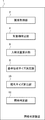
- FIG. 1 is a diagram showing an outline of an interest determination device 1 according to an embodiment of the present disclosure.
- the interest determination device 1 is, for example, a computer.
- the interest determination device 1 includes an image acquisition unit 2, an object identification unit 4, an incident light amount calculation unit 6, a reference pupil size determination unit 8, a pupil size calculation unit 10, and an interest determination unit 12.
- the image acquisition unit 2 functions as an image acquisition means.
- the object identification unit 4 functions as an object identification means.
- the incident light amount calculation unit 6 functions as an incident light amount calculation means.
- the reference pupil size determining unit 8 functions as a reference pupil size determining means.
- the pupil size calculation unit 10 functions as a pupil size calculation means.
- the interest determination unit 12 functions as an interest determination means.
- the image acquisition unit 2 acquires at least an image in which the eyes of the target person are photographed.
- the target person is a person who is the target of interest determination.
- the object identification unit 4 identifies an object in the line-of-sight direction of the target person by using the acquired image.
- the object is an object that the target person is gazing at and is a target for determining whether or not the target person is interested.
- the incident light amount calculation unit 6 calculates the incident light amount representing the amount of light incident on the eyes of the target person by using the acquired image.
- the reference pupil size determination unit 8 determines the reference pupil size based on the calculated incident light amount.
- the pupil size calculation unit 10 calculates the pupil size of the target person using the acquired image.
- the interest determination unit 12 determines the interest of the target person in the object by comparing the determined reference pupil size with the calculated pupil size.
- the interest determination device 1 identifies an object in the line-of-sight direction of the target person using the acquired image, and calculates the amount of incident light on the eyes of the target person. Thereby, the target person can determine the interest of the target person in the object without wearing a special device such as a luminance meter, an eyeball photographing device, a face photographing device, a visual scene photographing device, and a brightness measuring device. Therefore, the interest determination device 1 according to the present embodiment can determine the interest of the target person in the object under an arbitrary environment.
- the interest determination method executed by the interest determination device 1 it is possible to determine the interest of the target person for the object under an arbitrary environment. Further, even if a program that executes the interest determination method is used, it is possible to determine the interest of the target person for the object under an arbitrary environment. Further, even if the interest determination device 1 and at least one imaging device (camera) are used, it is possible to determine the interest of the target person in the object under any environment.
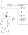
- FIG. 2 is a diagram showing the configuration of the interest determination system 20 according to the first embodiment.
- the interest determination system 20 according to the first embodiment includes cameras 30A and 30B, and an interest determination device 100.
- the interest determination device 100 corresponds to the interest determination device 1 shown in FIG.
- the cameras 30A and 30B are described without distinction, they may be referred to as the camera 30.
- the camera 30 is, for example, an imaging device installed in a store or the like.
- the interest determination system 20 may be provided with three or more cameras 30. Alternatively, the interest determination system 20 may be provided with only one camera 30. That is, the interest determination system 20 has at least one imaging device (camera 30).
- the camera 30 photographs the eyes 82 of the target person 80. Then, the camera 30 generates an image (image data) in which at least the eyes of the target person are captured. Further, the camera 30 can take a picture of the object 90 in the line-of-sight direction of the eyes 82 of the target person 80. That is, the object 90 is an object to be watched by the target person 80.
- the camera 30A may photograph the target person 80 (eyes 82), and the camera 30B may photograph the object 90. That is, the camera 30A may be provided at a position where the target person 80 can be photographed. Further, the camera 30B may be provided at a position where the object 90 can be photographed.
- one camera 30 may take a picture of the eyes 82 of the target person 80 and the object 90.
- image may also mean "image data indicating an image” as a processing target in information processing. Further, the image may be a still image or a moving image.
- the interest determination device 100 is, for example, a computer.
- the interest determination device 100 is communicably connected to the camera 30 via a wired or wireless connection.
- the interest determination device 100 acquires an image in which at least the eyes 82 of the target person 80 are taken.
- the interest determination device 100 uses this image to identify an object in the line-of-sight direction of the target person 80.
- the interest determination device 100 calculates the amount of incident light representing the amount of light incident on the eyes 82 of the target person 80 using the image.
- the interest determination device 100 determines the reference pupil size based on the calculated incident light amount.
- the interest determination device 100 calculates the pupil size of the target person using the image. Then, the interest determination device 100 determines the interest of the target person 80 in the object 90 by comparing the determined reference pupil size with the calculated pupil size.
- the interest determination device 100 has a CPU 102 (Central Processing Unit), a ROM 104 (Read Only Memory), a RAM 106 (Random Access Memory), and an interface unit 108 (IF; Interface) as a main hardware configuration.
- the CPU 102, ROM 104, RAM 106, and interface unit 108 are connected to each other via a data bus or the like.
- the CPU 102 has a function as an arithmetic unit that performs control processing, arithmetic processing, and the like.
- the ROM 104 has a function for storing a control program, an arithmetic program, and the like executed by the CPU 102.
- the RAM 106 has a function for temporarily storing processing data and the like.
- the interface unit 108 inputs and outputs signals to and from the outside via wired or wireless. In addition, the interface unit 108 accepts a data input operation by the user and displays the information to the user. For example, the interface unit 108 communicates with the camera 30.
- FIG. 3 is a functional block diagram showing the interest determination device 100 according to the first embodiment.
- the interest determination device 100 includes an image acquisition unit 110, an eye area identification unit 112, a line-of-sight direction estimation unit 114, an object identification unit 116, and an incident light amount calculation unit 120. Further, the interest determination device 100 includes a reference pupil size determination unit 130, a table storage unit 132, a pupil size calculation unit 134, an interest determination unit 140, and a determination result output unit 142. Further, the incident light amount calculation unit 120 includes an object brightness calculation unit 122 and an eye region illuminance calculation unit 126.
- the image acquisition unit 110, the eye area identification unit 112, the line-of-sight direction estimation unit 114, the object identification unit 116, and the incident light amount calculation unit 120 are the image acquisition means, the eye area identification means, the line-of-sight direction estimation means, and the object identification, respectively. It functions as a means and a means for calculating the amount of incident light. Further, the object brightness calculation unit 122 and the eye area illuminance calculation unit 126 function as the object brightness calculation means and the eye area illuminance calculation means, respectively.
- the reference pupil size determination unit 130, the table storage unit 132, the pupil size calculation unit 134, and the determination result output unit 142 function as reference pupil size determination means, table storage means, pupil size calculation means, and determination result output means, respectively. To do.
- Each component shown in FIG. 3 can be realized, for example, by the CPU 102 executing a program stored in the ROM 104. Further, the necessary program may be recorded on an arbitrary non-volatile recording medium and installed if necessary. It should be noted that each component is not limited to being realized by software as described above, and may be realized by some hardware such as a circuit element. In addition, one or more of the above components may be realized by physically separate hardware. The specific functions of each component will be described later.
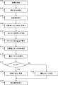
- FIG. 4 is a flowchart showing an interest determination method performed by the interest determination device 100 according to the first embodiment.
- the image acquisition unit 110 acquires an image from the camera 30 via the interface unit 108 (step S102). Specifically, the image acquisition unit 110 may acquire an image taken by the eyes 82 of the target person 80 from the camera 30A. Further, the image acquisition unit 110 may acquire an image of the object 90 taken from the camera 30B.
- the interest determination device 100 estimates the line-of-sight direction of the target person 80 using the image acquired in the process of S102 (step S104).
- the eye area specifying unit 112 detects the eye area of the eye 82 of the target person 80 from the image output from the camera 30A. The detection of this eye region can be realized by, for example, an object detection technique using a learning model obtained by machine learning. Further, the eye region identification unit 112 detects the white eye region (sclera) in the detected eye region. Then, the eye area specifying unit 112 acquires the color information (R, G, B) of the white eye area.
- the line-of-sight direction estimation unit 114 estimates the line-of-sight direction of the target person 80 from the detected eye area.
- the gaze direction can be estimated by an existing method.
- the line-of-sight direction estimation unit 114 detects the orientation of the face of the target person 80 by using the image in which the face of the target person 80 is captured.
- the line-of-sight direction estimation unit 114 detects the position of the center of the pupil in the eye region. Then, the line-of-sight direction estimation unit 114 estimates the line-of-sight direction from the direction of the face and the position of the center of the pupil.
- the object identification unit 116 identifies the object 90 in the line-of-sight direction of the target person 80 (step S106). Specifically, the object identification unit 116 identifies the object 90 by using the image output from the camera 30B. More specifically, the object identification unit 116 obtains the line-of-sight direction estimated by the processing of S104 from the positions and angles of view of the cameras 30A and 30B from the camera 30B from the coordinate system in the image output from the camera 30A. Geometrically transform to the coordinate system in the output image. As a result, the object identification unit 116 maps the line-of-sight direction vector to the image output from the camera 30B. Then, the object identification unit 116 identifies the object at the tip of the line-of-sight direction vector as the object 90.
- the incident light amount calculation unit 120 calculates the incident light amount representing the amount of light incident on the eyes 82 of the target person 80 using the image acquired in the process of S102 (S108 to S112).
- the object brightness calculation unit 122 calculates the brightness L of the object 90 using the image acquired in the process of S102 (step S108). That is, the object brightness calculation unit 122 (incident light amount calculation unit 120) calculates the brightness L in the region of the object 90 in the image acquired by the process of S102. An example of a specific calculation method of the brightness L will be described later.
- Eye area illumination calculation unit 126 by using the image obtained in the processing in S102, and calculates the illuminance E A in the eye 82 of the target person 80 (step S110). That is, the eye region illuminance calculation unit 126 (incident light amount calculation unit 120) uses the brightness (color information) in the eye 82 region (white eye region) of the target person 80 in the image acquired by the process of S102 to obtain the eyes of the target person 80. calculating the illuminance E a at 82. It will be described later examples of the specific method for calculating the illuminance E A.
- Incident light intensity calculator 120 calculates the amount of incident light EE to the eye 82 of the target person 80 (step S112).
- the incident light intensity calculator 120, the amount of incident light EE, function showing the relationship between the brightness L and the illuminance E A EE f (L, E A) is used to calculate the amount of incident light EE.
- An example of a specific calculation method of the incident light amount EE will be described later.
- the object brightness calculation unit 122 calculates the brightness L of the object 90 in the color image captured by the camera 30B. It is assumed that the color image is composed of an RGB color space. It is assumed that the chromaticity of the RGB phosphor and the chromaticity of white with respect to the RGB color space can be specified in advance as the color characteristics of the camera 30B. Further, it is assumed that the RGB data (color information) can be uniquely converted into the tristimulus value XYZ.
- MRX is a 3 ⁇ 3 transformation matrix.
- the conversion formula is not limited to the above formula 1, and it is sufficient that the RGB value can be uniquely converted to the XYZ value.
- the conversion formula may be defined as a form in which a quadratic term is added, as in the following formula 2.
- M'RX is a 3 ⁇ 9 transformation matrix.
- M RX and M 'RX may be calculated in advance by performing the camera color calibration with known color patches.
- the tristimulus value Y representing the brightness can be converted into the absolute brightness L (cd / m 2 ). That is, the object brightness calculation unit 122 (incident light amount calculation unit 120) may calculate the absolute brightness L in the region of the object 90 in the image.
- the aperture value F, shutter speed, and gain of the lens are set in order to obtain an appropriate exposure.
- the gain is set to 1.0.
- the tristimulus value Y corresponding to the pixel values (R, G, B) on the captured image with respect to the absolute brightness L, which is the amount of light incident on the camera is two variables of the lens aperture value F and the shutter speed. Can be decided.
- the camera to be used is calibrated in advance. Specifically, the pixel values (R, G, B) of the captured image when the amount of incident light (absolute brightness L (cd / m 2 )), the lens aperture value F, and the shutter speed S are changed. From, the relationship between the tristimulus values Y obtained by the formula 1 or the formula 2 and these values is grasped.
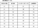
- an absolute brightness table (Lookup table (LUT)) for obtaining an absolute brightness L, which is the amount of incident light corresponding to the lens aperture value F, the shutter speed S, and the tristimulus value Y, is obtained. It is generated (see Figure 5).
- the lens aperture value F and the shutter speed S of the camera at the time of shooting are recorded, and the tristimulus value Y corresponding to the pixel value (R, G, B) of the region of the object 90 in the image captured under that condition is calculated.
- the absolute brightness L (cd / m 2 ) which is the amount of incident light with respect to the tristimulus value Y or the like, is determined.
- the average value of the tristimulus values Y corresponding to each pixel may be used.
- the absolute brightness may be calculated using the LUT for each of the tristimulus values corresponding to each pixel, and the average value of the absolute brightness obtained for each pixel may be calculated as the absolute brightness L.
- FIG. 5 is a diagram illustrating an absolute brightness table (LUT) used by the object brightness calculation unit 122 according to the first embodiment.
- the absolute brightness table may be stored in the table storage unit 132 described later.
- the aperture value F and the shutter speed S are changed to take an image of a completely white plate.
- the amount of light incident on the camera 30 from the completely white plate is L1 and L2
- the aperture values are F1 and F2
- the shutter speeds are S1 and S2.
- the LUT as illustrated in FIG. 5 is generated by obtaining the tristimulus value Y with respect to the pixel value of each captured image when the images are photographed under eight combinations of the above conditions by Equation 1 or Equation 2.
- the object brightness calculation unit 122 calculates the tristimulus value Yx from the pixel values of the images taken at the aperture value F1 and the shutter speed S2. Then, the object brightness calculation unit 122 compares the tristimulus values Y2 and Y6 at the aperture value F1 and the shutter speed S2 of the LUT illustrated in FIG. 5 with the tristimulus value Yx, and performs an interpolation calculation (interpolation calculation) which is an existing method.
- the amount of incident light Lx is calculated by (interpolation) or the like. When creating this LUT, it is possible to take pictures under many conditions instead of the above eight conditions to expand the amount of information in the LUT. As a result, a more accurate amount of incident light can be obtained.
- the relationship between the amount of incident light, the lens aperture value F, the shutter speed S, and the image output value (pixel value) may differ depending on the camera model or individual difference. Therefore, by performing calibration for each camera, it is possible to calculate the absolute brightness L (cd / m 2 ) with higher accuracy.
- the eye region illuminance calculation unit 126 calculates the apparent irradiance at each pixel position of the reflector in the image.
- the reflector corresponds to the white eye region (sclera) of the eye 82. Therefore, the eye area illuminance calculation unit 126 calculates the illuminance of the target person 80 in the eyes 82 from the color information in the white eye area.
- FIG. 6 is a diagram for explaining a method of calculating irradiance according to the first embodiment.
- FIG. 6 shows an all-around light environment model considering a surface light source. In this model, it is assumed that any point of the reflector (white-eyed region) is located at the center A of the sphere, and there is no obstruction between the light source and the center A, and the radiance distribution of the light source from the entire periphery is calculated. Observe. Let this radiance distribution be L ( ⁇ , ⁇ ). Here, ⁇ represents the zenith angle and ⁇ represents the azimuth.
- the illuminance E A at the center A receives the incident light energy received from the light source represented by the minute zenith angle d ⁇ i and the minute azimuth d ⁇ i and the minute solid angle d ⁇ i in all directions. It is the integral in.
- the above calculation is conditional on the light reflection characteristic of the reflector being Lambertian reflection.
- Lambertian reflection white eyes
- it is not necessarily Lambertian reflection, but since it is a situation where a minute object called an eye is observed from a distance, the light reflected at the center A is centered from all directions.
- the ambient light incident on A is integrated, and is constant regardless of the viewpoint direction. Therefore, it can be said that the above calculation method is appropriate.
- the luminance value I A in the recorded reflectors as an image is represented by the product of the illuminance E a and the surface reflectance S a of the reflector.
- the brightness value I A is used tristimulus value Y is calculated using Equation 1 or Equation 2 described above, and the aperture value F of the camera lens at the time of shooting, the shutter speed, the absolute brightness can be determined from the gain You may.
- the brightness value I A has a reflect the spectral sensitivity characteristics of the camera is expressed as a function of the wavelength ⁇ of light.
- the wavelength ⁇ can be regarded as a constant. Therefore, (the k r, g, b) the luminance value I A k at point A is represented by the following formula 5 so.
- ⁇ k is the camera gain. That is, the equation 5, the illuminance E A k at point A (white eye area), may be calculated from the luminance value I A (color information) and the camera gain at point A.
- the illuminance E A of visible light at the point A (white eye region) can be obtained by adding E A r , E A g , and E A b .
- the illuminance E A is calculated from the color information in the white eye area.
- the illuminance EE incident light amount considering the influence of the light from the object 90 that the target person 80 is paying attention to can be expressed by the following equation 7.
- EE E1 + E A ⁇ ( 7) Therefore, the incident light intensity calculator 120, using Equation 6 and Equation 7, the luminance L calculated in the processing of S108, and from the illuminance E A calculated in the processing of S110, and calculates the amount of incident light EE.
- the reference pupil size determination unit 130 determines the reference pupil size D0 using the incident light amount EE calculated in the process of S112 (step S114). Specifically, the reference pupil size determination unit 130 determines the reference pupil size D0 using the reference pupil size table stored in the table storage unit 132.
- the "reference pupil size” is the size of the pupil diameter that changes due to the light reflex with respect to the brightness under illumination and the brightness of the object 90. In other words, the reference pupil size is the pupil size in which the change in the pupil size due to the interest (emotion) of the target person 80 with respect to the object 90 is not taken into consideration.
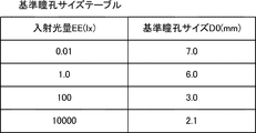
- FIG. 7 is a diagram illustrating a reference pupil size table according to the first embodiment.
- the reference pupil size table associates the incident light amount EE (illuminance) with the reference pupil size.
- the size of the pupil diameter when the incident light amount is 0.01, 1.0, 100, 10000 (lpx) is 7.0, 6.0, 3.0, 2.1 (mm), respectively.
- the size of the pupil diameter with respect to the illuminance is defined as the reference pupil size.
- the table storage unit 132 stores the LUT showing the relationship between the amount of incident light (illuminance) and the reference pupil size as a reference pupil size table.
- the reference pupil size determination unit 130 calculates the size of the pupil diameter (reference pupil size) with respect to the incident light amount EE (illuminance) by using the reference pupil size table illustrated in FIG. 7. As the calculation method, an existing method such as interpolation calculation (interpolation) can be used. If a function indicating the reference pupil size table can be prepared in advance, the reference pupil size determining unit 130 can calculate the reference pupil size by substituting the incident light amount EE into the function.
- the pupil size calculation unit 134 calculates the pupil size D1 of the eyes 82 of the target person 80 (step S116). Specifically, the pupil size calculation unit 134 calculates the pupil size D1 of the eyes 82 of the target person 80 who is gazing at the object 90 by using the image acquired in the process of S102. More specifically, the pupil size calculation unit 134 detects the pupil region in the eye region specified by the eye region identification unit 112. Then, the pupil size calculation unit 134 calculates the size of the pupil region.
- the pupil size calculation unit 134 determines the pupil size (number of pixels) from the ratio of the pupil diameter (number of pixels) to the iris diameter (number of pixels) in the image. Pupil diameter) D1 (mm) may be calculated.
- the interest determination unit 140 compares the reference pupil size D0 with the pupil size D1 and determines the interest of the target person 80 in the object 90 (S120 to S124). Specifically, the interest determination unit 140 determines whether or not the pupil size D1 is larger than the reference pupil size D0 (step S120). When the pupil size D1 is larger than the reference pupil size D0 (YES in S120), the interest determination unit 140 determines that the target person 80 is interested in the object 90 (step S122). On the other hand, when the pupil size D1 is equal to or less than the reference pupil size D0 (NO in S120), the interest determination unit 140 determines that the target person 80 is not interested in the object 90 (step S124). Then, the determination result output unit 142 outputs the determination result by the interest determination unit 140 (step S126).
- the interest determination unit 140 determines whether or not the target person 80 is interested in the object 90, but the configuration is not limited to this.
- the interest determination unit 140 may determine the degree of interest of the target person 80 with respect to the object 90.
- the degree of interest may be expressed by the following equation 8. (D1-D0) / D0 ... (8)
- the interest determination device 100 calculates the amount of incident light incident on the eyes 82 of the target person 80 using the image taken by the camera 30, and the reference pupil is based on the amount of incident light. Determine the size. Then, the interest determination device 100 according to the first embodiment determines the interest of the target person 80 in the object 90 by comparing the reference pupil size and the pupil size. As a result, the target person 80 determines the interest of the target person 80 in the object 90 without wearing a special device such as a luminance meter, an eyeball photographing device, a face photographing device, a visual scene photographing device, and a brightness measuring device. it can. Therefore, the interest determination device 100 according to the embodiment can determine the interest of the target person in the object under any environment.
- the interest determination device 100 is configured to calculate the incident light amount by calculating the brightness of the object 90 using the image taken by the object 90.
- the target person 80 can determine the interest of the target person 80 in the object 90 without wearing a luminance meter or the like. Further, even if the object 90 is not a display such as a monitor, the interest of the target person 80 in the object 90 can be determined.
- the interest determination device 100 is configured to calculate the incident light amount by calculating the absolute brightness of the object 90 by using the pixel value in the region of the object 90 in the image. .. This makes it possible to accurately calculate the amount of incident light due to the light from the object 90, regardless of the settings of the camera 30 or the like.
- the interest determination device 100 is configured to calculate the incident light amount by calculating the illuminance in the eyes 82 of the target person 80 using an image.
- the target person 80 can determine the interest of the target person 80 in the object 90 without wearing a brightness measuring device or the like.
- the interest determination device 100 calculates the illuminance in the eyes 82 of the target person 80 using an image, and is incident based on the brightness in the object 90 and the illuminance in the eyes 82 of the target person 80. It is configured to calculate the amount of light. Even in an environment of the same brightness (illuminance), if the brightness (luminance) of the object 90 to be watched is different, the size of the pupil may be different. For example, even in a dark environment, when the target person 80 gazes at a bright object 90, the pupil of the target person 80 can be small. On the contrary, even in a bright environment, when the target person 80 gazes at the dark object 90, the pupil of the target person 80 can be enlarged.
- the reference pupil size can be obtained more accurately by using both the luminance in the object 90 and the illuminance in the eyes 82 of the subject 80. Then, in the first embodiment, when determining the reference pupil size, the amount of incident light is calculated based on the brightness of the object 90 and the illuminance of the target person 80 at the eyes 82. Therefore, the interest determination device 100 according to the first embodiment can calculate the incident light amount more accurately, so that the reference pupil size can be determined more accurately. This makes it possible to more accurately determine the interest of the target person 80 in the object 90.
- the interest determination device 100 is configured to calculate the illuminance in the eyes 82 of the target person 80 from the color information in the white eye region of the eyes 82 of the target person 80 in the image. This makes it possible to accurately calculate the amount of incident light due to ambient light using an image.
- the present invention is not limited to the above embodiment, and can be appropriately modified without departing from the spirit.
- the order of each process in the flowchart shown in FIG. 4 can be changed as appropriate.
- one or more of the processing of the flowchart shown in FIG. 4 may not be necessary.
- one or more of the processes of S104 to S114 may be executed after the process of S116.
- one or more of the processes of S104 to S108 may be executed after the process of S110.
- one of the processing of S108 and the processing of S110 may not be performed.
- Non-temporary computer-readable media include various types of tangible storage media.
- Examples of non-temporary computer-readable media include magnetic recording media (eg, flexible disks, magnetic tapes, hard disk drives), magneto-optical recording media (eg, magneto-optical disks), CD-ROMs (Read Only Memory), CD-Rs, Includes CD-R / W and semiconductor memory (for example, mask ROM, PROM (Programmable ROM), EPROM (Erasable PROM), flash ROM, RAM (RandomAccessMemory)).
- the program may also be supplied to the computer by various types of transient computer readable medium.
- Examples of temporary computer-readable media include electrical, optical, and electromagnetic waves.
- the temporary computer-readable medium can supply the program to the computer via a wired communication path such as an electric wire and an optical fiber, or a wireless communication path.
- Appendix 1 At least an image acquisition means for acquiring an image of the target person's eyes, An object specifying means for identifying an object in the line-of-sight direction of the target person using the image, and An incident light amount calculating means for calculating an incident light amount representing the amount of light incident on the eyes of the target person using the image, and A reference pupil size determining means for determining a reference pupil size based on the amount of incident light, A pupil size calculating means for calculating the pupil size of the target person using the image, and An interest determination device having an interest determination means for determining an interest of the target person in the object by comparing the reference pupil size with the pupil size.
- the image acquisition means acquires an image in which the object is captured, and obtains an image.
- the interest determination device according to Appendix 1, wherein the incident light amount calculation means calculates the incident light amount by calculating the brightness of the object using the image.
- the interest determination device according to Appendix 2, wherein the incident light amount calculating means calculates the incident light amount by calculating the absolute brightness of the object by using the pixel value in the region of the object in the image.
- the incident light amount calculation means calculates the illuminance in the eyes of the target person using the image, and calculates the incident light amount based on the brightness in the object and the illuminance in the eyes of the target person.
- the interest determination device according to 2 or 3.
- the image acquisition means is an interest determination system that acquires the image captured by the imaging device.
- Appendix 8 At least get the image of the target person's eyes, Using the image, an object in the line-of-sight direction of the target person is identified. Using the image, the amount of incident light representing the amount of light incident on the eyes of the target person was calculated. The reference pupil size is determined based on the amount of incident light, and Using the image, the pupil size of the target person was calculated. An interest determination method for determining an interest of the target person in the object by comparing the reference pupil size with the pupil size. (Appendix 9) Acquire the image in which the object was taken, The interest determination method according to Appendix 8, wherein the incident light amount is calculated by calculating the brightness of the object using the image.
- Appendix 10 The interest determination method according to Appendix 9, which calculates the amount of incident light by calculating the absolute brightness of the object using the pixel values in the region of the object in the image.
- Appendix 11 The interest determination according to Appendix 9 or 10, wherein the illuminance in the eyes of the target person is calculated using the image, and the incident light amount is calculated based on the brightness in the object and the illuminance in the eyes of the target person.
- Method Appendix 12
- the interest determination method according to Appendix 8 which calculates the amount of incident light by calculating the illuminance in the eyes of the target person using the image.
- Appendix 13 The method for determining interest according to Appendix 11 or 12, wherein the illuminance in the eyes of the target person is calculated from the color information in the white eye region of the eyes of the target person in the image.
- Appendix 14 At least the steps to get the image of the target person's eyes, Using the image, a step of identifying an object in the line-of-sight direction of the target person, and Using the image, a step of calculating the amount of incident light representing the amount of light incident on the eyes of the target person, and The step of determining the reference pupil size based on the amount of incident light, Using the image, the step of calculating the pupil size of the target person and A non-transitory computer-readable medium containing a program that causes a computer to perform a step of determining an interest of the target person in the object by comparing the reference pupil size with the pupil size.
- Interest judgment device 2 Image acquisition unit 4
- Object identification unit 6 Incident light amount calculation unit 8
- Reference pupil size determination unit 10 Pupil size calculation unit 12
- Interest judgment unit 20 Interest judgment system 30
- Camera 100
- Interest judgment device 110 Image acquisition unit 112 Eye area Specific unit 114 Line-of-sight direction estimation unit 116 Object specific unit 120
- Incident light amount calculation unit 122 Object brightness calculation unit 126
- Eye area illuminance calculation unit 130 Reference pupil size determination unit 132
- Table storage unit 134 Pupil size calculation unit 140
- Interest judgment unit 142 Judgment Result output section
Landscapes
- Engineering & Computer Science (AREA)
- Health & Medical Sciences (AREA)
- Life Sciences & Earth Sciences (AREA)
- Physics & Mathematics (AREA)
- General Health & Medical Sciences (AREA)
- General Physics & Mathematics (AREA)
- Multimedia (AREA)
- Theoretical Computer Science (AREA)
- Animal Behavior & Ethology (AREA)
- Molecular Biology (AREA)
- Ophthalmology & Optometry (AREA)
- Veterinary Medicine (AREA)
- Public Health (AREA)
- Surgery (AREA)
- Biophysics (AREA)
- Medical Informatics (AREA)
- Biomedical Technology (AREA)
- Heart & Thoracic Surgery (AREA)
- Human Computer Interaction (AREA)
- Developmental Disabilities (AREA)
- Educational Technology (AREA)
- Pathology (AREA)
- Child & Adolescent Psychology (AREA)
- Social Psychology (AREA)
- Psychology (AREA)
- Software Systems (AREA)
- Psychiatry (AREA)
- Hospice & Palliative Care (AREA)
- Eye Examination Apparatus (AREA)
- Measurement Of The Respiration, Hearing Ability, Form, And Blood Characteristics Of Living Organisms (AREA)
- Image Processing (AREA)
Abstract
L'invention concerne un dispositif de détermination d'intérêt qui est capable de déterminer un intérêt d'une personne sujet dans un article sujet dans un environnement donné. Une unité d'acquisition d'image (2) acquiert une image dans laquelle au moins les yeux d'une personne sujet sont capturés. Une unité d'identification d'article sujet (4), à l'aide de l'image acquise, identifie un article sujet présent dans une direction du regard de la personne sujet. Une unité de calcul de quantité de lumière incidente (6), à l'aide de l'image acquise, calcule une quantité de lumière incidente qui représente la quantité de lumière incidente sur les yeux de la personne sujet. Une unité de détermination de taille de pupille de référence (8) détermine une taille de pupille de référence sur la base de la quantité de lumière incidente calculée. Une unité de calcul de taille de pupille (10), à l'aide de l'image acquise, calcule la taille de la pupille de la personne sujet. Une unité de détermination d'intérêt (12) détermine l'intérêt d'une personne sujet dans l'article sujet en comparant la taille de pupille de référence déterminée à la taille de pupille calculée.
Priority Applications (3)
| Application Number | Priority Date | Filing Date | Title |
|---|---|---|---|
| US17/439,898 US11887349B2 (en) | 2019-03-26 | 2019-03-26 | Interest determination apparatus, interest determination system, interest determination method, and non-transitory computer readable medium storing program |
| PCT/JP2019/012946 WO2020194529A1 (fr) | 2019-03-26 | 2019-03-26 | Dispositif de détermination d'intérêt, système de détermination d'intérêt, procédé de détermination d'intérêt, et support non transitoire lisible par ordinateur dans lequel un programme est stocké |
| JP2021508491A JP7207520B2 (ja) | 2019-03-26 | 2019-03-26 | 興味判定装置、興味判定システム、興味判定方法及びプログラム |
Applications Claiming Priority (1)
| Application Number | Priority Date | Filing Date | Title |
|---|---|---|---|
| PCT/JP2019/012946 WO2020194529A1 (fr) | 2019-03-26 | 2019-03-26 | Dispositif de détermination d'intérêt, système de détermination d'intérêt, procédé de détermination d'intérêt, et support non transitoire lisible par ordinateur dans lequel un programme est stocké |
Publications (1)
| Publication Number | Publication Date |
|---|---|
| WO2020194529A1 true WO2020194529A1 (fr) | 2020-10-01 |
Family
ID=72609385
Family Applications (1)
| Application Number | Title | Priority Date | Filing Date |
|---|---|---|---|
| PCT/JP2019/012946 Ceased WO2020194529A1 (fr) | 2019-03-26 | 2019-03-26 | Dispositif de détermination d'intérêt, système de détermination d'intérêt, procédé de détermination d'intérêt, et support non transitoire lisible par ordinateur dans lequel un programme est stocké |
Country Status (3)
| Country | Link |
|---|---|
| US (1) | US11887349B2 (fr) |
| JP (1) | JP7207520B2 (fr) |
| WO (1) | WO2020194529A1 (fr) |
Cited By (2)
| Publication number | Priority date | Publication date | Assignee | Title |
|---|---|---|---|---|
| WO2022107288A1 (fr) * | 2020-11-19 | 2022-05-27 | 日本電信電話株式会社 | Dispositif d'estimation, procédé d'estimation et programme d'estimation |
| WO2022239793A1 (fr) * | 2021-05-12 | 2022-11-17 | 株式会社夏目綜合研究所 | Dispositif d'analyse de sujet |
Families Citing this family (1)
| Publication number | Priority date | Publication date | Assignee | Title |
|---|---|---|---|---|
| CN117314559B (zh) * | 2023-09-21 | 2024-08-02 | 淮阴工学院 | 一种基于用户瞳孔反应的个性化商品优化推送方法和系统 |
Citations (7)
| Publication number | Priority date | Publication date | Assignee | Title |
|---|---|---|---|---|
| JP2010197656A (ja) * | 2009-02-25 | 2010-09-09 | Hitachi Ltd | 映像表示装置 |
| JP2011002401A (ja) * | 2009-06-22 | 2011-01-06 | Yokogawa Electric Corp | 輝度測定装置における補正係数算出方法および輝度測定装置 |
| WO2011042989A1 (fr) * | 2009-10-09 | 2011-04-14 | Kikuchi Kouichi | Dispositif de détermination du sentiment d'un spectateur pour une scène reconnue visuellement |
| WO2015072202A1 (fr) * | 2013-11-18 | 2015-05-21 | ソニー株式会社 | Dispositif de traitement des informations, procédé et programme de détection de la fatigue oculaire sur la base du diamètre des pupilles |
| JP2017510203A (ja) * | 2014-03-31 | 2017-04-06 | ノキア テクノロジーズ オーユー | 画像取り込みを制御するための方法および装置 |
| CN108052973A (zh) * | 2017-12-11 | 2018-05-18 | 中国人民解放军战略支援部队信息工程大学 | 基于多项眼动数据的地图符号用户兴趣分析方法 |
| WO2018100875A1 (fr) * | 2016-11-30 | 2018-06-07 | ソニー株式会社 | Appareil de traitement d'informations, procédé de traitement d'informations, et programme |
Family Cites Families (19)
| Publication number | Priority date | Publication date | Assignee | Title |
|---|---|---|---|---|
| US5859686A (en) * | 1997-05-19 | 1999-01-12 | Northrop Grumman Corporation | Eye finding and tracking system |
| JPH11101935A (ja) * | 1997-09-26 | 1999-04-13 | Canon Inc | 注視状態検出装置及び電子機器の制御装置 |
| US7306337B2 (en) * | 2003-03-06 | 2007-12-11 | Rensselaer Polytechnic Institute | Calibration-free gaze tracking under natural head movement |
| JP2006050233A (ja) | 2004-08-04 | 2006-02-16 | Konica Minolta Photo Imaging Inc | 撮像装置、画像処理装置、画像処理方法およびプログラム |
| US20100010370A1 (en) | 2008-07-09 | 2010-01-14 | De Lemos Jakob | System and method for calibrating and normalizing eye data in emotional testing |
| US9618322B2 (en) * | 2011-12-28 | 2017-04-11 | Wavelight Gmbh | Process for optical coherence tomography and apparatus for optical coherence tomography |
| US20140155763A1 (en) * | 2012-12-03 | 2014-06-05 | Ben F. Bruce | Medical analysis and diagnostic system |
| TWI533224B (zh) * | 2013-11-14 | 2016-05-11 | 原相科技股份有限公司 | 眼球偵測裝置、瞳孔偵測方法與虹膜辨識方法 |
| WO2015081325A1 (fr) * | 2013-11-27 | 2015-06-04 | Shenzhen Huiding Technology Co., Ltd. | Suivi d'un œil et détection de la réaction de l'utilisateur |
| US9961258B2 (en) * | 2015-02-23 | 2018-05-01 | Facebook, Inc. | Illumination system synchronized with image sensor |
| WO2016143759A1 (fr) | 2015-03-06 | 2016-09-15 | 株式会社 脳機能研究所 | Dispositif d'estimation d'émotion et procédé d'estimation d'émotion |
| US11170514B2 (en) * | 2015-10-27 | 2021-11-09 | Canon Kabushiki Kaisha | Image processing apparatus, image processing method, 3D printing system, and storage medium |
| IL242895B (en) * | 2015-12-03 | 2021-04-29 | Eyeway Vision Ltd | Image projection system |
| US20210169417A1 (en) * | 2016-01-06 | 2021-06-10 | David Burton | Mobile wearable monitoring systems |
| US20180120933A1 (en) * | 2016-10-28 | 2018-05-03 | Ocular Data Systems, Inc. | Image-based system, having interchangeable vision elements, to observe and document eye responses |
| US10728616B2 (en) * | 2017-04-19 | 2020-07-28 | Intel Corporation | User interest-based enhancement of media quality |
| AU2019236239A1 (en) * | 2018-03-16 | 2020-11-05 | REBIScan, Inc. | Apparatus and method for ophthalmic neural scanning |
| US20200302825A1 (en) * | 2019-03-21 | 2020-09-24 | Dan Sachs | Automated selection and titration of sensory stimuli to induce a target pattern of autonomic nervous system activity |
| JP7494862B2 (ja) * | 2019-12-24 | 2024-06-04 | 日本電気株式会社 | 情報処理装置、制御方法及びプログラム |
-
2019
- 2019-03-26 WO PCT/JP2019/012946 patent/WO2020194529A1/fr not_active Ceased
- 2019-03-26 US US17/439,898 patent/US11887349B2/en active Active
- 2019-03-26 JP JP2021508491A patent/JP7207520B2/ja active Active
Patent Citations (7)
| Publication number | Priority date | Publication date | Assignee | Title |
|---|---|---|---|---|
| JP2010197656A (ja) * | 2009-02-25 | 2010-09-09 | Hitachi Ltd | 映像表示装置 |
| JP2011002401A (ja) * | 2009-06-22 | 2011-01-06 | Yokogawa Electric Corp | 輝度測定装置における補正係数算出方法および輝度測定装置 |
| WO2011042989A1 (fr) * | 2009-10-09 | 2011-04-14 | Kikuchi Kouichi | Dispositif de détermination du sentiment d'un spectateur pour une scène reconnue visuellement |
| WO2015072202A1 (fr) * | 2013-11-18 | 2015-05-21 | ソニー株式会社 | Dispositif de traitement des informations, procédé et programme de détection de la fatigue oculaire sur la base du diamètre des pupilles |
| JP2017510203A (ja) * | 2014-03-31 | 2017-04-06 | ノキア テクノロジーズ オーユー | 画像取り込みを制御するための方法および装置 |
| WO2018100875A1 (fr) * | 2016-11-30 | 2018-06-07 | ソニー株式会社 | Appareil de traitement d'informations, procédé de traitement d'informations, et programme |
| CN108052973A (zh) * | 2017-12-11 | 2018-05-18 | 中国人民解放军战略支援部队信息工程大学 | 基于多项眼动数据的地图符号用户兴趣分析方法 |
Cited By (5)
| Publication number | Priority date | Publication date | Assignee | Title |
|---|---|---|---|---|
| WO2022107288A1 (fr) * | 2020-11-19 | 2022-05-27 | 日本電信電話株式会社 | Dispositif d'estimation, procédé d'estimation et programme d'estimation |
| JPWO2022107288A1 (fr) * | 2020-11-19 | 2022-05-27 | ||
| JP7444286B2 (ja) | 2020-11-19 | 2024-03-06 | 日本電信電話株式会社 | 推定装置、推定方法、および、推定プログラム |
| WO2022239793A1 (fr) * | 2021-05-12 | 2022-11-17 | 株式会社夏目綜合研究所 | Dispositif d'analyse de sujet |
| JP2022174805A (ja) * | 2021-05-12 | 2022-11-25 | 株式会社夏目綜合研究所 | 被験者分析装置 |
Also Published As
| Publication number | Publication date |
|---|---|
| US20220189132A1 (en) | 2022-06-16 |
| JP7207520B2 (ja) | 2023-01-18 |
| US11887349B2 (en) | 2024-01-30 |
| JPWO2020194529A1 (fr) | 2020-10-01 |
Similar Documents
| Publication | Publication Date | Title |
|---|---|---|
| US11503219B2 (en) | Image processing apparatus, image capture apparatus, and control method for adding an effect of a virtual light source to a subject | |
| US10587795B2 (en) | System for producing compliant facial images for selected identification documents | |
| JP7264257B2 (ja) | 制御装置、制御方法及びプログラム | |
| US10996751B2 (en) | Training of a gaze tracking model | |
| US20190281269A1 (en) | Method and apparatus for determining fisheye camera shadow correction parameter | |
| CN109565577A (zh) | 色彩校正装置、色彩校正系统、色彩校正用全息图、色彩校正方法以及程序 | |
| JP7207520B2 (ja) | 興味判定装置、興味判定システム、興味判定方法及びプログラム | |
| US11336944B2 (en) | Method for controlling a display parameter of a mobile device and computer program product | |
| KR102251307B1 (ko) | 거리측정 기능을 갖는 열상 카메라 시스템 | |
| TW202420231A (zh) | 用於mura檢測和demura的方法和系統 | |
| US20110141316A1 (en) | Image processing apparatus and image processing method | |
| US9906705B2 (en) | Image pickup apparatus | |
| US12495216B2 (en) | Electronic apparatus and image processing method | |
| US12190771B2 (en) | Display system and display method | |
| CN115546883B (zh) | 眼底图像处理系统 | |
| KR20220079753A (ko) | 얼굴 인식에 기초하여 촬영 대상의 온도를 측정하는 방법 | |
| CN118329391A (zh) | 一种ar光波导杂散光的测试方法及系统 | |
| JP2021179815A (ja) | 瞳孔径変化を用いた視線計測用キャリブレーション方法及び装置、並びに視線計測装置及びカメラ装置 | |
| KR20180000580A (ko) | 조명기를 구비한 스테레오 매칭 시스템에서의 코스트 볼륨 연산장치 및 그 방법 | |
| US20240031545A1 (en) | Information processing apparatus, information processing method, and storage medium | |
| JP2020129313A (ja) | 処理装置、処理システム、撮像装置、処理方法、プログラム、および記録媒体 | |
| JP7311995B2 (ja) | 画像処理装置及び画像処理方法、プログラム、記憶媒体 | |
| Krüger et al. | 71‐4: Imaging Luminance Measuring Devices (ILMDs)‐Characterization and Standardization with Respect to Display Measurements | |
| JP2017026519A (ja) | 処理装置、その制御方法、及びキャリブレーション装置 | |
| US12217645B2 (en) | Calibration system for display apparatus and operating method thereof |
Legal Events
| Date | Code | Title | Description |
|---|---|---|---|
| 121 | Ep: the epo has been informed by wipo that ep was designated in this application |
Ref document number: 19920883 Country of ref document: EP Kind code of ref document: A1 |
|
| ENP | Entry into the national phase |
Ref document number: 2021508491 Country of ref document: JP Kind code of ref document: A |
|
| NENP | Non-entry into the national phase |
Ref country code: DE |
|
| 122 | Ep: pct application non-entry in european phase |
Ref document number: 19920883 Country of ref document: EP Kind code of ref document: A1 |