WO2020194655A1 - Climatiseur - Google Patents
Climatiseur Download PDFInfo
- Publication number
- WO2020194655A1 WO2020194655A1 PCT/JP2019/013568 JP2019013568W WO2020194655A1 WO 2020194655 A1 WO2020194655 A1 WO 2020194655A1 JP 2019013568 W JP2019013568 W JP 2019013568W WO 2020194655 A1 WO2020194655 A1 WO 2020194655A1
- Authority
- WO
- WIPO (PCT)
- Prior art keywords
- heat exchanger
- compressor
- temperature
- indoor heat
- air conditioner
- Prior art date
- Legal status (The legal status is an assumption and is not a legal conclusion. Google has not performed a legal analysis and makes no representation as to the accuracy of the status listed.)
- Ceased
Links
Images





Classifications
-
- F—MECHANICAL ENGINEERING; LIGHTING; HEATING; WEAPONS; BLASTING
- F24—HEATING; RANGES; VENTILATING
- F24F—AIR-CONDITIONING; AIR-HUMIDIFICATION; VENTILATION; USE OF AIR CURRENTS FOR SCREENING
- F24F11/00—Control or safety arrangements
- F24F11/70—Control systems characterised by their outputs; Constructional details thereof
- F24F11/80—Control systems characterised by their outputs; Constructional details thereof for controlling the temperature of the supplied air
- F24F11/86—Control systems characterised by their outputs; Constructional details thereof for controlling the temperature of the supplied air by controlling compressors within refrigeration or heat pump circuits
-
- F—MECHANICAL ENGINEERING; LIGHTING; HEATING; WEAPONS; BLASTING
- F25—REFRIGERATION OR COOLING; COMBINED HEATING AND REFRIGERATION SYSTEMS; HEAT PUMP SYSTEMS; MANUFACTURE OR STORAGE OF ICE; LIQUEFACTION SOLIDIFICATION OF GASES
- F25B—REFRIGERATION MACHINES, PLANTS OR SYSTEMS; COMBINED HEATING AND REFRIGERATION SYSTEMS; HEAT PUMP SYSTEMS
- F25B1/00—Compression machines, plants or systems with non-reversible cycle
Definitions
- the present invention relates to an air conditioner.
- Patent Document 1 when the hydrophilic precoat fins of the indoor heat exchanger are frosted during the dehumidifying operation, the temperature of the indoor heat exchanger is relatively high when the outside air temperature is high.
- the rotation speed of the outdoor blower of the outdoor unit and the opening degree of the electric expansion valve are controlled according to the outside air temperature. That is, as the outside air temperature rises, the rotation speed of the outdoor blower of the outdoor unit is increased and the opening degree of the electric expansion valve is decreased. As a result, the temperature of the indoor heat exchanger can be lowered, and the indoor heat exchanger can be frozen and frosted on the hydrophilic pre-coated fins.
- the inventors have conducted various studies, and it is necessary for the freeze-cleaning operation to correspond to various construction conditions such as operating temperature conditions, pipe length, number of connected rooms, and other heat capacities of the system.
- the high-pressure pressure during freezing operation (during freezing treatment) at a low outside air temperature and a high outside air temperature is different, and depending on the combination of the low-pressure pressure at the target freezing temperature, the discharge temperature of the compressor may be excessively increased or decreased. It can significantly impair reliability.
- the target freezing temperature is reached, if the outlet of the indoor heat exchanger reaches a superheated state, the heat exchange performance may deteriorate in the superheated region and the product may not freeze.
- the present invention is an invention for solving the above-mentioned problems, and an object of the present invention is to provide an air conditioner capable of appropriately freezing an indoor heat exchanger and ensuring the reliability of a compressor.
- the air conditioner of the present invention includes a refrigerant circuit in which the refrigerant circulates in the refrigeration cycle via the compressor, the condenser, the expansion valve, and the evaporator in order, and at least the compressor and the expansion valve.
- One of the condenser and the evaporator is an outdoor heat exchanger and the other is an indoor heat exchanger, and the control unit makes the indoor heat exchanger function as an evaporator and indoors.
- the operating frequency of the compressor is controlled based on the temperature of the indoor heat exchanger, and the dryness of the intake refrigerant of the compressor or the discharge refrigerant temperature of the compressor is used. It is characterized in that the opening degree of the expansion valve is controlled.
- the indoor heat exchanger can be appropriately frozen and the reliability of the compressor can be ensured.
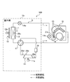
- FIG. 1 is a configuration diagram of an air conditioner 100 according to the first embodiment.
- the air conditioner 100 is a device that performs air conditioning such as heating operation and cooling operation.
- the air conditioner 100 includes an outdoor unit Uo, an indoor unit Ui, and a control unit 30 (see FIG. 3).
- the outdoor unit Uo includes an outdoor heat exchanger 12, an outdoor fan 13, an outdoor expansion valve 14a, a compressor 11, an accumulator 29, and a four-way valve 17.
- the indoor unit Ui includes an indoor heat exchanger 15, an indoor fan 16, and an indoor expansion valve 14b.
- the compressor 11 is a device that compresses a low-temperature low-pressure gas refrigerant and discharges it as a high-temperature high-pressure gas refrigerant. As shown in FIG. 1, the compressor 11 includes a compressor motor 11a as a drive source.
- the four-way valve 17 is a valve that switches the flow path of the refrigerant according to the operation mode of the air conditioner 100.
- the outdoor heat exchanger 12 is a heat exchanger in which heat is exchanged between the refrigerant passing through the heat transfer tube (not shown) and the outside air sent from the outdoor fan 13.
- the outdoor fan 13 is a fan that sends outside air to the outdoor heat exchanger 12.
- the outdoor fan 13 includes an outdoor fan motor 13a as a drive source, and is arranged in the vicinity of the outdoor heat exchanger 12.
- the outdoor expansion valve 14a and the indoor expansion valve 14b are valves that reduce the pressure of the refrigerant condensed by the "condenser" (one of the outdoor heat exchanger 12 and the indoor heat exchanger 15).
- the decompressed refrigerant at least one of the outdoor expansion valve 14a and the indoor expansion valve 14b is guided to the "evaporator" (the other of the outdoor heat exchanger 12 and the indoor heat exchanger 15).
- the indoor heat exchanger 15 is a heat exchange in which heat exchange is performed between the refrigerant flowing through the heat transfer tube g (see FIG. 2) and the indoor air (air in the air conditioning target space) sent from the indoor fan 16. It is a vessel.
- the indoor fan 16 is a fan that sends indoor air to the indoor heat exchanger 15.
- the indoor fan 16 has an indoor fan motor 16c (see FIG. 3) as a drive source, and is arranged in the vicinity of the indoor heat exchanger 15.
- the compressor 11 the outdoor heat exchanger 12 (condenser), the outdoor expansion valve 14a (expansion valve), and the indoor expansion valve 14b (expansion valve).
- the indoor heat exchanger 15 evaporator
- the refrigerant (gas) vaporized by the indoor heat exchanger 15 is introduced into the outdoor unit Uo, circulates through the four-way valve 17, and flows into the accumulator 29.
- the accumulator 29 is a shell-shaped member that separates the refrigerant into gas and liquid.
- the accumulator 29 functions as a buffer tank for storing the refrigerant (liquid) when the liquid refrigerant flows in excessively transiently, thereby preventing the liquid compression in the compressor 11. Therefore, the dryness of the refrigerant increases in the accumulator 29, and the highly dry refrigerant flows into the compressor 11.
- the compressor 11 the indoor heat exchanger 15 (condenser), the indoor expansion valve 14b (expansion valve), and the outdoor expansion valve 14a (expansion valve).
- the outdoor heat exchanger 12 evaporator
- the refrigerant circulates in the refrigeration cycle.
- the refrigerant (gas) compressed by the compressor 11 is introduced into the indoor unit Ui via the four-way valve 17.
- the refrigerant (gas) introduced into the indoor unit Ui flows into the indoor heat exchanger 15 and is cooled and condensed by heat exchange with the indoor air blown by the indoor fan 16. At this time, the refrigerant (gas) condensed in the indoor heat exchanger 15 gives the heat of condensation to the indoor air to heat the indoor air.
- the refrigerant (liquid) condensed by the indoor heat exchanger 15 is introduced into the outdoor unit 10 via the indoor expansion valve 14b.
- the refrigerant (liquid) introduced into the outdoor unit 10 is decompressed by the outdoor expansion valve 14a and flows into the outdoor heat exchanger 12.
- the refrigerant (liquid) that has flowed into the outdoor heat exchanger 12 is vaporized by heat exchange with the outside air blown by the outdoor fan 13, and flows into the accumulator 29 via the four-way valve 17. Then, the refrigerant (gas or gas-liquid two-phase state) whose dryness is increased by the accumulator 29 flows into the compressor 11.
- the outdoor unit Uo has a discharge temperature sensor 28b that measures the temperature (discharge temperature Td) of the refrigerant discharged by the compressor 11, and measures the pressure of the refrigerant (discharge pressure Pd) on the outlet side of the compressor 11.
- the discharge pressure sensor 28d and the suction pressure sensor 28e for measuring the pressure of the refrigerant (suction pressure Ps) on the inlet side of the compressor 11 are provided. Instead of the discharge temperature Td, the temperature of the upper part of the chamber of the compressor 11 may be measured and used. Further, one or a plurality of the above-mentioned sensors may be omitted as appropriate.
- the outdoor unit Uo is provided with an outdoor heat exchanger temperature sensor 28c for measuring the condensation temperature Tc (during cooling operation) or the evaporation temperature Te (during heating operation) of the refrigerant in the outdoor heat exchanger 12, and is provided indoors.
- the machine Ui is provided with an indoor heat exchanger temperature sensor 27c for measuring the evaporation temperature Te (during cooling operation) or the condensation temperature Tc (during heating operation) of the refrigerant in the indoor heat exchanger 15.
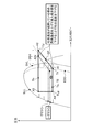
- FIG. 2 is a vertical cross-sectional view of the indoor unit Ui.
- the indoor unit Ui in addition to the indoor heat exchanger 15 and the indoor fan 16 described above, the indoor unit Ui includes a drain pan 18 (also referred to as a dew pan), a housing base 19, and filters 20a and 20b. I have. Further, the indoor unit Ui includes a front panel 21, a left and right wind direction plate 22, and a vertical wind direction plate 23.
- the indoor heat exchanger 15 includes a plurality of fins f and a plurality of heat transfer tubes g penetrating the fins f. From another point of view, the indoor heat exchanger 15 includes a front indoor heat exchanger 15a arranged on the front side of the indoor fan 16 and a rear indoor heat exchanger 15b arranged on the rear side of the indoor fan 16. And have. In the example shown in FIG. 2, the upper end portion of the front indoor heat exchanger 15a and the upper end portion of the rear indoor heat exchanger 15b are connected in an inverted V shape.
- the indoor fan 16 is, for example, a cylindrical cross-flow fan, and is arranged in the vicinity of the indoor heat exchanger 15.
- the indoor fan 16 includes a plurality of fan blades 16a, an annular partition plate 16b on which these fan blades 16a are installed, and an indoor fan motor 16c (see FIG. 3) as a drive source.
- the drain pan 18 receives the condensed water of the indoor heat exchanger 15 and is arranged below the indoor heat exchanger 15.
- the housing base 19 is a housing in which devices such as an indoor heat exchanger 15 and an indoor fan 16 are installed.
- the filters 20a and 20b collect dust from the air toward the indoor heat exchanger 15 as the indoor fan 16 is driven.
- One filter 20a is arranged on the front side of the indoor heat exchanger 15, and the other filter 20b is arranged on the upper side of the indoor heat exchanger 15.
- the front panel 21 is a panel installed so as to cover the filter 20a on the front side, and is rotatable forward with the lower end as an axis.
- the front panel 21 may not rotate.
- the left and right wind direction plate 22 is a plate-shaped member that adjusts the wind direction of the air blown into the room in the left and right direction.
- the left and right wind direction plates 22 are arranged in the blowout air passage h3, and are rotated in the left and right directions by the left and right wind direction plate motors 24 (see FIG. 3).
- the vertical wind direction plate 23 is a plate-shaped member that adjusts the vertical wind direction of the air blown into the room.
- the vertical wind direction plate 23 is arranged near the air outlet h4, and is rotated in the vertical direction by the vertical wind direction plate motor 25 (see FIG. 3).
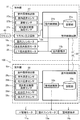
- FIG. 3 is a functional block diagram of the air conditioner 100.
- the indoor unit Ui shown in FIG. 3 includes a remote controller transmission / reception unit 26, an indoor environment detection unit 27, and an indoor control circuit 31 in addition to the above-described configurations.
- the remote control transmission / reception unit 26 exchanges predetermined information with the remote control 40 by infrared communication or the like.
- the indoor environment detection unit 27 includes an indoor temperature sensor 27a, a humidity sensor 27b, and an indoor heat exchanger temperature sensor 27c.
- the indoor temperature sensor 27a is a sensor that detects the temperature in the room (space subject to air conditioning), and is installed on the air suction side of the filters 20a and 20b (see FIG. 2), for example.
- the humidity sensor 27b is a sensor that detects the humidity of the indoor air, and is installed at a predetermined position of the indoor unit Ui.
- the indoor heat exchanger temperature sensor 27c is a sensor that detects the temperature of the indoor heat exchanger 15 (see FIG. 2), and is installed in the indoor heat exchanger 15. The detected values of the indoor temperature sensor 27a, the humidity sensor 27b, and the indoor heat exchanger temperature sensor 27c are output to the indoor control circuit 31.
- the indoor control circuit 31 includes electronic circuits such as a CPU (Central Processing Unit), a ROM (Read Only Memory), a RAM (Random Access Memory), and various interfaces. Then, the program stored in the ROM is read out and expanded in the RAM, and the CPU executes various processes.
- a CPU Central Processing Unit
- ROM Read Only Memory
- RAM Random Access Memory
- the indoor control circuit 31 includes a storage unit 31a and an indoor control unit 31b.
- the storage unit 31a stores data received via the remote controller transmission / reception unit 26, detection values of each sensor, and the like.
- the indoor control unit 31b controls the indoor fan motor 16c, the left and right wind direction plate motor 24, the vertical wind direction plate motor 25, the indoor expansion valve 14b, and the like based on the data stored in the storage unit 31a.
- the outdoor unit Uo includes an outdoor environment detection unit 28 and an outdoor control circuit 32 in addition to those described with reference to FIG.
- the outdoor environment detection unit 28 includes an outdoor temperature sensor 28a, a discharge temperature sensor 28b, an outdoor heat exchanger temperature sensor 28c, a discharge pressure sensor 28d, and a suction pressure sensor 28e.
- the detected value of each sensor including the outdoor temperature sensor 28a is output to the outdoor control circuit 32.
- the outdoor control circuit 32 includes electronic circuits such as a CPU, ROM, RAM, and various interfaces, and is connected to the indoor control circuit 31 via a communication line. As shown in FIG. 3, the outdoor control circuit 32 includes a storage unit 32a and an outdoor control unit 32b.
- the storage unit 32a stores data and the like received from the room control circuit 31.
- the outdoor control unit 32b controls the compressor motor 11a, the outdoor fan motor 13a, the outdoor expansion valve 14a, and the like based on the data stored in the storage unit 32a.
- the indoor control circuit 31 and the outdoor control circuit 32 are collectively referred to as a “control unit 30”.
- FIG. 4 is a flowchart of a process related to freeze cleaning of the indoor heat exchanger 15. Refer to FIGS. 1, 2 and 3 as appropriate. The processing of the control unit 30 regarding the freeze-cleaning of the indoor heat exchanger 15 will be described with reference to FIG.
- step S101 of FIG. 4 the control unit 30 freezes the indoor heat exchanger 15. That is, the control unit 30 causes the indoor heat exchanger 15 to function as an evaporator, frosts the moisture in the air on the indoor heat exchanger 15, and freezes the indoor heat exchanger 15.
- the control unit 30 drives the compressor 11 (see FIG. 1) to increase the opening degree of the outdoor expansion valve 14a (first expansion valve), and the indoor expansion valve 14b (second expansion valve). Controls the opening of the valve). For example, the control unit 30 makes the opening degree of the indoor expansion valve 14b smaller than that during the cooling operation.
- the outdoor expansion valve 14a may be set to an opening degree larger than the opening degree of the indoor expansion valve 14b in order to reduce the flow path loss in the piping.
- the low-pressure refrigerant having a low evaporation temperature flows into the indoor heat exchanger 15, so that the moisture in the air is frosted in the indoor heat exchanger 15, and the frost and ice (reference numeral i shown in FIG. 5) are further formed. Becomes easier to grow.
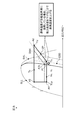
- FIG. 5 is an explanatory diagram showing a state in which the indoor heat exchanger 15 is being thawed.
- the control unit 30 stops devices such as the indoor fan 16 and the compressor 11 (see FIG. 1).
- the frost and ice (reference numeral i shown in FIG. 5) of the indoor heat exchanger 15 are naturally thawed at room temperature, and a large amount of water w flows down to the drain pan 18 along the fin f.
- the dust j adhering to the indoor heat exchanger 15 is washed away.
- control unit 30 may perform a heating operation or a ventilation operation to dry the inside of the indoor unit Ui. As a result, the growth of fungi and other fungi in the indoor unit Ui can be suppressed.
- FIG. 6 is an explanatory diagram showing a state diagram of the refrigerant during the freezing process.
- FIG. 7 is an explanatory diagram showing a problem during the freezing process.
- CP is the compression process
- DSH is the discharge superheat
- EDD is the isothermal diagram (Etc. Dryness diagram)
- II is the isothermal line (Isentropic line).
- ISS is the isothermal line of superheated steam (Isotherms superheated steam)
- ISL is the isotherms of supercooled liquid
- IWS is the isotherm wet steam
- SLL is the saturated liquid.
- the line (Saturated liquid line) and SVL indicate a saturated vapor line (Saturated vapor line).
- the freezing temperature is created by each actuator such as the operating frequency F of the compressor 11 (rotational speed Fr of the compressor 11), the outdoor expansion valve 14a, and the indoor expansion valve 14b.
- the discharge temperature Td of the compressor 11 may overheat or the outlet of the indoor heat exchanger 15 during freezing may overheat.
- the refrigerant (gas) in the state of point A1 is compressed by the compressor 14 (compression step CP).
- the temperature (specific enthalpy) and pressure rise to the state of point A2, which is introduced into the outdoor heat exchanger 12.
- the refrigerant (gas) introduced into the outdoor heat exchanger 12 condenses at substantially equal pressure to a state of point A3 (a state in the liquid or gas-liquid two-phase region), and the indoor expansion valve via the outdoor expansion valve 14a. Introduced in 14b.
- the refrigerant (liquid) introduced into the indoor expansion valve 14b in the state of point A3 is decompressed by the indoor expansion valve 14b to reach the state of point A4, and is vaporized by the indoor heat exchanger 15 to the state of point A1 (gas). Become.
- the refrigerant circulates while transitioning between the states of points A1 to A4. That is, when the refrigerant decompressed by the indoor expansion valve 14b (point A3 ⁇ A4) evaporates at the indoor heat exchanger 15 (point A4 ⁇ A1), the indoor heat exchanger 15 freezes.
- the refrigerant on the outlet side of the outdoor heat exchanger 12 during the freezing process at point 3 is in the gas-liquid two-phase region.
- the freezing power of the indoor heat exchanger 15 is reduced (point A1a in FIG. 7). That is, it becomes difficult to freeze in the downstream region of the indoor heat exchanger 15.
- the discharge temperature Td (discharge refrigerant temperature) of the compressor 11 excessively rises.
- the discharge temperature Td (discharge refrigerant temperature) of the compressor 11 excessively rises.
- the discharge temperature Td (discharge refrigerant temperature) of the compressor 11 may excessively drop.
- the freezing power is less dependent on the amount of refrigerant circulating, and depends on the indoor heat exchanger temperature TE, that is, the freezing temperature.
- the amount of refrigerant circulation is not controlled, but the indoor heat exchanger temperature TE, that is, the freezing temperature, and the dryness of the refrigerant on the inlet side of the compressor 11 (hereinafter referred to as "suction dryness Xs").
- the discharge temperature Td (discharge refrigerant temperature) of the compressor 11 is controlled so as to be a predetermined target, so that the indoor heat exchanger 15 can be appropriately frozen and the reliability of the compressor 11 can be compatible. ..
- FIG. 8 is an explanatory diagram showing a control target in the refrigerant phase diagram during the freezing process according to the first embodiment.
- the liquid pipe temperature and the evaporation temperature Te (indoor heat exchanger temperature TE) are adjusted by controlling the operating frequency (rotational speed control) of the compressor 11.
- the intake refrigerant temperature (suction temperature Ts) and the discharge refrigerant temperature (discharge temperature Td) are adjusted by controlling the opening degree of the indoor expansion valve 14b.
- FIG. 9 is a flowchart showing the details of the process for freezing the indoor heat exchanger 15 according to the first embodiment (S101 in FIG. 4). Refer to FIGS. 1 to 4 as appropriate.
- the control unit 30 makes initial settings.
- Initial setting items include freezing time (time from the start of freezing treatment to the end of freezing treatment), target indoor heat exchanger temperature TL 0 , target discharge temperature Td 0, etc., which are temperatures that are criteria for freezing. ..
- step S12 the control unit 30 controls the four-way valve 17. That is, the control unit 30 controls the four-way valve 17 so that the outdoor heat exchanger 12 functions as a condenser and the indoor heat exchanger 15 functions as an evaporator. If the cooling operation is performed immediately before the "freezing process" (see FIG. 5), the control unit 30 maintains the state of the four-way valve 17 in step S12.
- step S13 the control unit 30 sets the rotation speed of the compressor 11. That is, the control unit 30 sets the rotation speed of the compressor motor 11a based on the outdoor temperature, which is the detection value of the outdoor temperature sensor 28a, and drives the compressor 11.
- the control unit 30 When freezing the indoor heat exchanger 15, the control unit 30 increases the rotation speed of the compressor motor 11a as the outdoor temperature increases. This is because, in order to remove heat from the indoor air in the indoor heat exchanger 15, it is necessary that the outdoor heat exchanger 12 sufficiently dissipates heat accordingly. For example, when the outdoor temperature is relatively high, the control unit 30 increases the temperature and pressure of the refrigerant discharged from the compressor 11 by increasing the rotation speed of the compressor motor 11a. As a result, heat exchange in the outdoor heat exchanger 12 is appropriately performed, and by extension, freezing of the indoor heat exchanger 15 is also appropriately performed.
- the operating frequency (rotational speed) of the compressor 11 may be set by using a map (data table) or a predetermined mathematical formula.
- the rotation speed of the compressor 11 is often controlled based on the temperature of the refrigerant discharged from the compressor 11 (discharge temperature Td) or the like.
- discharge temperature Td discharge temperature
- the indoor heat exchanger temperature since the freezing force depends on the temperature of the indoor heat exchanger 15, in step S30 described later, during the freezing process of the indoor heat exchanger 15, as described above, the indoor heat exchanger temperature. Control based on TE.
- step S14 the control unit 30 adjusts the opening degree of the indoor expansion valve 14b.
- step S14 it is desirable that the opening degree of the indoor expansion valve 14b is smaller than that during normal cooling operation.
- the refrigerant having a lower temperature and lower pressure than that during the normal cooling operation flows into the indoor heat exchanger 15 via the indoor expansion valve 14b. Therefore, the water adhering to the indoor heat exchanger 15 is likely to freeze, and the power consumption required for freezing the indoor heat exchanger 15 can be reduced.
- step S15 the control unit 30 stops the indoor fan 16.
- the control unit 30 may stop the indoor fan 16 or the indoor fan 16 may be stopped. May be driven at a predetermined rotation speed. In either case, the indoor heat exchanger 15 is frozen.
- step S16 the control unit 30 sets the rotation speed of the outdoor fan 33. That is, the control unit 30 sets the rotation speed of the outdoor fan 33 based on the rotation speed of the compressor motor 11a. For example, the higher the rotation speed of the compressor motor 11a, the higher the rotation speed of the outdoor fan 13.
- step S20 the control unit 30 controls the operating frequency F (rotation speed Fr of the compressor 11) of the compressor 11 (see FIG. 10 for details), and in step S30, the control unit 30 expands the room.
- the opening degree V of the valve 14b is controlled (see FIG. 11 for details).
- step S40 the control unit 30 determines whether or not the predetermined freeze end condition is satisfied, and if the freeze end condition is satisfied (S40: Yes), the process is terminated and the freeze end condition is not satisfied (S40). : No), the process returns to step S20. Specifically, assuming that the freezing end condition is a predetermined time after the start of the freezing process, it is determined whether or not the freezing process has reached the freezing time set in step S11. It may be terminated under other freeze termination conditions.
- the control unit 30 has a first predetermined time from the start of the freezing process until the indoor heat exchanger temperature TE falls below the freezing point, or a second predetermined time longer than the first predetermined time.
- the freezing process should be completed. As a result, the freezing process can be terminated without being unnecessarily continued.
- the control unit 30 may control the operating frequency F of the compressor 11 at a preset upper limit operating frequency Fmax or less and a lower limit operating frequency Fmin or more. This is to give priority to the protection of the compressor 11.
- FIG. 10 is a flowchart showing a process of operating frequency control (rotational speed control) of the compressor 11 according to the first embodiment.
- the control unit 30 reads the indoor heat exchanger temperature TL (indoor heat exchanger temperature TE) from the indoor heat exchanger temperature sensor 27c (step S21), sets the indoor heat exchanger temperature TL and the target indoor heat exchanger temperature TL 0 .
- ⁇ TL which is the difference between the two, is calculated (step S22), and it is determined whether or not ⁇ TL is positive (> 0) (step S23). If ⁇ TL is positive (step S23, Yes), the control unit 30 adds a predetermined value ⁇ F to the operating frequency F of the compressor 11 (step S24), and proceeds to step S25. That is, if the indoor heat exchanger 15 is not sufficiently cooled at the current rotation speed of the compressor 11, the rotation speed is increased. On the other hand, if ⁇ TL is not positive (steps S23, No), the process proceeds to step S25.
- step S25 the control unit 30 determines whether or not ⁇ TL is negative ( ⁇ 0). If ⁇ TL is negative (step S25, Yes), the control unit 30 subtracts a predetermined value ⁇ F from the operating frequency F of the compressor 11 (step S26), and proceeds to step S30 (see FIG. 9). That is, since the indoor heat exchanger 15 is sufficiently cold at the current rotation speed of the compressor 11, the rotation speed is reduced. On the other hand, if ⁇ TL is not negative (steps S25 and No), the process proceeds to step S30 (see FIG. 9).
- FIG. 11 is a flowchart showing a process of controlling the opening degree of the indoor expansion valve 14b according to the first embodiment.
- the control unit 30 reads the discharge temperature Td from the discharge temperature sensor 28b (step S31), calculates ⁇ Td which is the difference between the discharge temperature Td and the target discharge temperature Td 0 (step S32), and ⁇ Td is positive (> 0). It is determined whether or not it is (step S33). If ⁇ Td is positive (step S33, Yes), the control unit 30 adds a predetermined value ⁇ V to the opening V of the indoor expansion valve 14b (step S34), and proceeds to step S35. As a result, the control unit 30 lowers the discharge temperature Td. On the other hand, if ⁇ Td is not positive (steps S33, No), the process proceeds to step S35.
- step S35 the control unit 30 determines whether or not ⁇ Td is negative ( ⁇ 0). If ⁇ Td is negative (step S35, Yes), the control unit 30 subtracts a predetermined value ⁇ V from the opening V of the indoor expansion valve 14b (step S36), and proceeds to step S40 (see FIG. 9). As a result, the control unit 30 raises the discharge temperature Td. On the other hand, if ⁇ Td is not negative (steps S35 and No), the process proceeds to step S40 (see FIG. 9).
- step S32 ⁇ Xs is calculated by the equation (1).
- ⁇ Xs Xs-Xs 0 ... (1)
- Xs 0 is the target inhalation dryness.
- the control unit 30 may adjust the opening degree V of the indoor expansion valve 14b according to the positive or negative of ⁇ Xs. That is, when ⁇ Xs is positive, the opening V of the indoor expansion valve 14b may be increased, and when ⁇ Xs is negative, the opening V of the indoor expansion valve 14b may be decreased.
- the control unit 30 determines at least the refrigerant discharge temperature Td in the compressor 11, the refrigerant discharge pressure Pd in the compressor 11, the suction pressure Ps in the compressor 11, and the rotation speed Fr of the compressor 11. ,
- the inhalation dryness Xs may be estimated by the calculation based on.
- FIG. 12 is an explanatory diagram showing an example of a temporal change in the temperature of the indoor heat exchanger 15.
- the target indoor heat exchanger temperature TL 0 has a set width (dead zone). This has a set range because it is affected by chattering and noise when controlled at one point.
- the set width is the difference between the target temperature Td 1 and the target temperature Td 2 .
- the target temperature Td 1 is a value obtained by adding a predetermined value ⁇ TL 0 to the target indoor heat exchanger temperature TL 0
- the target temperature Td 2 is a value obtained by subtracting a predetermined value ⁇ TL 0 from the target indoor heat exchanger temperature TL 0 .
- the horizontal axis of FIG. 12 is the elapsed time from the start of the freezing process.
- the vertical axis of FIG. 12 is the indoor heat exchanger temperature TE.
- the indoor heat exchanger temperature TE rapidly freezes based on the relative humidity of the indoor air (air-conditioned space) and the like.
- the control unit 30 lowers the operating frequency F of the compressor 11 (see time t 21 ).
- the indoor heat exchanger temperature TE rises.
- the control unit 30 increases the operating frequency F of the compressor 11 (see time t 22). After that, when the freezing time is reached, the control unit 30 ends the freezing process and shifts to the next step (for example, drying process).
- the target indoor heat exchanger temperature TL 0 is set in advance, but the present invention is not limited to this.
- the control unit 30 controls the operating frequency of the compressor 11 based on the target temperature of the indoor heat exchanger 15 (target indoor heat exchanger temperature TL 0 ), and also controls the operating frequency of the compressor 11.
- the target temperature of the indoor heat exchanger 15 is changed.
- the control unit 30 raises or lowers the target indoor heat exchanger temperature TL 0 (target freezing temperature), giving priority to the reliability of the compressor 11 and the prevention of overheating at the outlet of the indoor heat exchanger 15. Let me.
- FIG. 13 is an explanatory diagram showing a correction for lowering the discharge temperature Td in the refrigerant phase diagram during the freezing process according to the second embodiment.
- the target discharge temperature Td 0 of the compressor 11 is represented by the equation (2) by the condensation temperature Tc and the target discharge superheat degree Td SH .
- Td 0 Tc + Td SH ... (2)
- Td SH A ⁇ + B ... (3)
- a and B are coefficients ⁇ is a pressure ratio which is a ratio of the discharge pressure Pd to the suction pressure Ps.
- the indoor heat exchanger 15 can be frozen at a surface temperature of less than 0 ° C., so that the freezing temperature is set to ⁇ 5 ° C., that is, the target. Raise the indoor heat exchanger temperature TL 0 from -15 ° C to -5 ° C. As a result, the point A2 can be changed to the point A2d. Therefore, when the discharge temperature Td is excessively raised, the discharge temperature Td can be lowered by raising the evaporation temperature and lowering the suction dryness Xs (less than 1). Therefore, the reliability of the compressor and the reliability of the equipment can be improved by preventing the heat exchange outlet from overheating.
- the control unit 30 controls the suction dryness Xs of the suction refrigerant in order to prevent overheating of the outlet of the indoor heat exchanger 15.
- the target indoor heat exchanger temperature TL 0 target freezing temperature
- the target suction dryness Xs 0 or the target discharge temperature Td 0 is adjusted slightly up or down. I try to bring it closer to the freezing temperature.
- FIG. 14 is an explanatory diagram showing an adjustment for raising the evaporation temperature in the refrigerant phase diagram during the freezing process according to the third embodiment.
- the evaporation temperature Te falls below the target value
- the evaporation temperature Te is raised by lowering the target suction dryness Xs 0 .
- the point A1 can be moved to the point A1b.
- the evaporation temperature Te falls below the target value
- the evaporation temperature Te is raised by lowering the target discharge temperature Td 0 .
- the point A1 can be moved to the point A1b.
- FIG. 15 is an explanatory diagram showing an adjustment for lowering the evaporation temperature in the refrigerant phase diagram during the freezing process according to the third embodiment.
- the evaporation temperature Te when the evaporation temperature Te is higher than the target value, the evaporation temperature is lowered by increasing the target suction dryness Xs 0 . As a result, the point A1 can be moved to the point A1c.
- the evaporation temperature Te is higher than the target value
- the evaporation temperature is lowered by raising the target discharge temperature Td 0 .
- the point A1 can be moved to the point A1c.
- the control unit 30 adjusts the suction dryness Xs by ⁇ 0.05. This makes it possible to bring the evaporation temperature Te of the indoor heat exchanger 15 closer to the target of ⁇ several ° C.
- the target indoor heat exchanger temperature TL 0 target freezing temperature
- the evaporation temperature Te is lower than -15 ° C
- the target suction dryness Xs 0 is lowered to raise the evaporation temperature Te. If the evaporation temperature Te exceeds ⁇ 15 ° C., the target suction dryness Xs 0 is increased and the evaporation temperature Te is decreased.
- the evaporation temperature Te is adjusted by raising or lowering the suction dryness Xs, but the present invention is not limited to this.
- the relationship between the freezing temperature and the suction dryness Xs changes depending on the high / low pressure ratio of the operating pressure. Therefore, the control unit 30 controls the air volume of the outdoor fan 13 to raise or lower the high pressure. It is also possible to change the balance between the freezing temperature and the suction dryness Xs.
- FIG. 16 is an explanatory diagram showing a change in cycle balance depending on the rotation speed of the outdoor fan 13 in the refrigerant phase diagram during the freezing process according to the fourth embodiment.
- the cycle S0 of points A1 ⁇ A2 ⁇ A3 ⁇ A4 ⁇ A1 can be changed to cycle S1 or changed to cycle S2 by adjusting the rotation speed of the outdoor fan 13.
- the evaporation temperature Te can be raised or lowered, and the pressure ratio ⁇ , the suction dryness Xs, and the discharge temperature Td can be corrected.
- the outdoor fan 13 may be controlled based on the pressure ratio ⁇ of the discharge pressure Pd and the suction pressure Ps or the discharge pressure Pd.
- step S20 of FIG. 10 the control of the operating frequency F of the compressor 11 is described based on the indoor heat exchanger temperature TE (target indoor heat exchanger temperature TL 0 ), but the control is not limited thereto.
- the control unit 30 may control the compressor 11 based on the pressure ratio ⁇ , which is the ratio of the discharge pressure Pd to the suction pressure Ps, or the discharge pressure Pd, instead of the indoor heat exchanger temperature TE.
- the indoor heat exchanger can be appropriately frozen and the reliability of the compressor can be ensured.
- the target chamber heat exchanger temperature TL 0 has been described as constant, but it may be lowered stepwise with the passage of time during the freezing process. As a result, the sound generated by the freezing phenomenon during the freezing process can be reduced.
- the present embodiment can also be applied to an air conditioner in which a supercooler is provided between the outdoor heat exchanger 13 and the outdoor expansion valve 14a.
- Each embodiment can be applied to any of a room air conditioner (RAC), a package air conditioner (PAC), and a building multi air conditioner (VRF).
- RAC room air conditioner
- PAC package air conditioner
- VRF building multi air conditioner
- each embodiment is described in detail in order to explain the present invention in an easy-to-understand manner, and is not necessarily limited to the one including all the configurations described. Further, it is possible to add / delete / replace a part of the configuration of each embodiment with another configuration.
- the above-mentioned mechanism and configuration show what is considered necessary for explanation, and do not necessarily show all the mechanisms and configurations in the product.
- Outdoor heat exchanger (condenser / evaporator) 13 Outdoor fan 14a Outdoor expansion valve (expansion valve, first expansion valve) 14b Indoor expansion valve (expansion valve, second expansion valve) 15 Indoor heat exchanger (evaporator / condenser) 16 Indoor fan 17 Four-way valve 18 Drain pan 19 Housing base 27 Indoor environment detector 27a Indoor temperature sensor 27b Humidity sensor 27c Indoor heat exchanger temperature sensor 28 Outdoor environment detector 28a Outdoor temperature sensor 28b Discharge temperature sensor 28c Outdoor heat exchanger temperature Sensor 28d Discharge pressure sensor 28e Suction pressure sensor 30 Control unit 40 Remote control 100 Air conditioner F Compressor operating frequency Fr Compressor rotation speed Fmax Upper limit operating frequency Fmin Lower limit operating frequency Tc Condensation temperature Te Evaporation temperature TE Indoor heat exchanger temperature (Indoor heat exchanger temperature) Td discharge temperature (discharge refrigerant temperature) Td 0 target discharge temperature (target discharge refrigerant temperature) Ts suction temperature (suction refrigerant temperature) TL 0 Target indoor heat exchange
Landscapes
- Engineering & Computer Science (AREA)
- Physics & Mathematics (AREA)
- Mechanical Engineering (AREA)
- Thermal Sciences (AREA)
- General Engineering & Computer Science (AREA)
- Chemical & Material Sciences (AREA)
- Combustion & Propulsion (AREA)
- Air Conditioning Control Device (AREA)
Abstract
La présente invention concerne un climatiseur qui comprend : un circuit de fluide frigorigène dans lequel un fluide frigorigène circule de façon séquentielle à travers un compresseur, un condenseur, un détendeur extérieur et un évaporateur; et une unité de commande qui commande au moins le compresseur et le détendeur. Un élément parmi le condenseur et l'évaporateur est un échangeur de chaleur externe et l'autre est un échangeur de chaleur interne. L'unité de commande amène l'échangeur de chaleur interne à fonctionner comme évaporateur, et commande la fréquence de fonctionnement du compresseur sur la base de la température de l'échangeur de chaleur interne pendant un traitement par congélation de congélation de l'échangeur de chaleur interne (étape S20), commande, de même, l'ouverture du détendeur sur la base de la siccité du fluide frigorigène aspiré dans le compresseur ou de la température du fluide frigorigène refoulé à partir du compresseur (étape S30).
Priority Applications (1)
| Application Number | Priority Date | Filing Date | Title |
|---|---|---|---|
| PCT/JP2019/013568 WO2020194655A1 (fr) | 2019-03-28 | 2019-03-28 | Climatiseur |
Applications Claiming Priority (1)
| Application Number | Priority Date | Filing Date | Title |
|---|---|---|---|
| PCT/JP2019/013568 WO2020194655A1 (fr) | 2019-03-28 | 2019-03-28 | Climatiseur |
Publications (1)
| Publication Number | Publication Date |
|---|---|
| WO2020194655A1 true WO2020194655A1 (fr) | 2020-10-01 |
Family
ID=72610316
Family Applications (1)
| Application Number | Title | Priority Date | Filing Date |
|---|---|---|---|
| PCT/JP2019/013568 Ceased WO2020194655A1 (fr) | 2019-03-28 | 2019-03-28 | Climatiseur |
Country Status (1)
| Country | Link |
|---|---|
| WO (1) | WO2020194655A1 (fr) |
Cited By (3)
| Publication number | Priority date | Publication date | Assignee | Title |
|---|---|---|---|---|
| CN113251636A (zh) * | 2021-05-10 | 2021-08-13 | 青岛海尔空调器有限总公司 | 一种空调器控制方法、装置、电子设备及空调器 |
| CN117168021A (zh) * | 2023-08-29 | 2023-12-05 | 浙江中广电器集团股份有限公司 | 一种空气源热泵机组及其补气制冷剂干度控制方法 |
| JP7615242B1 (ja) | 2023-08-08 | 2025-01-16 | 日立ジョンソンコントロールズ空調株式会社 | 空気調和機 |
Citations (3)
| Publication number | Priority date | Publication date | Assignee | Title |
|---|---|---|---|---|
| JP2016017673A (ja) * | 2014-07-07 | 2016-02-01 | 三菱電機株式会社 | 空気調和機 |
| JP2019039669A (ja) * | 2017-04-28 | 2019-03-14 | 日立ジョンソンコントロールズ空調株式会社 | 空気調和機 |
| JP6486586B1 (ja) * | 2018-10-05 | 2019-03-20 | 日立ジョンソンコントロールズ空調株式会社 | 空気調和機、空気調和機の制御方法およびプログラム |
-
2019
- 2019-03-28 WO PCT/JP2019/013568 patent/WO2020194655A1/fr not_active Ceased
Patent Citations (3)
| Publication number | Priority date | Publication date | Assignee | Title |
|---|---|---|---|---|
| JP2016017673A (ja) * | 2014-07-07 | 2016-02-01 | 三菱電機株式会社 | 空気調和機 |
| JP2019039669A (ja) * | 2017-04-28 | 2019-03-14 | 日立ジョンソンコントロールズ空調株式会社 | 空気調和機 |
| JP6486586B1 (ja) * | 2018-10-05 | 2019-03-20 | 日立ジョンソンコントロールズ空調株式会社 | 空気調和機、空気調和機の制御方法およびプログラム |
Cited By (4)
| Publication number | Priority date | Publication date | Assignee | Title |
|---|---|---|---|---|
| CN113251636A (zh) * | 2021-05-10 | 2021-08-13 | 青岛海尔空调器有限总公司 | 一种空调器控制方法、装置、电子设备及空调器 |
| JP7615242B1 (ja) | 2023-08-08 | 2025-01-16 | 日立ジョンソンコントロールズ空調株式会社 | 空気調和機 |
| JP2025024844A (ja) * | 2023-08-08 | 2025-02-21 | 日立ジョンソンコントロールズ空調株式会社 | 空気調和機 |
| CN117168021A (zh) * | 2023-08-29 | 2023-12-05 | 浙江中广电器集团股份有限公司 | 一种空气源热泵机组及其补气制冷剂干度控制方法 |
Similar Documents
| Publication | Publication Date | Title |
|---|---|---|
| EP3617609A1 (fr) | Climatiseur | |
| JP5472391B2 (ja) | コンテナ用冷凍装置 | |
| JP6975850B2 (ja) | 空気調和機 | |
| WO2018173120A1 (fr) | Déshumidificateur | |
| WO2011010473A1 (fr) | Pompe à chaleur | |
| JP5999171B2 (ja) | 空気調和装置 | |
| JPWO2020144797A1 (ja) | 空気調和機 | |
| JP4760974B2 (ja) | 冷凍装置 | |
| JP5370551B1 (ja) | コンテナ用冷凍装置 | |
| JP3835453B2 (ja) | 空気調和装置 | |
| CN114364933A (zh) | 空调机 | |
| CN118922677A (zh) | 空气调节装置 | |
| CN113614463A (zh) | 空调装置 | |
| JP5966327B2 (ja) | 空調室内機 | |
| WO2020194655A1 (fr) | Climatiseur | |
| JP6032330B2 (ja) | 空調機 | |
| JP4328892B2 (ja) | 調温調湿装置および環境試験装置 | |
| JP6808023B2 (ja) | 冷凍サイクル装置 | |
| CN113167486A (zh) | 空调机 | |
| JP2022041710A (ja) | 空気調和装置 | |
| WO2021176640A1 (fr) | Climatiseur | |
| JP2021156502A (ja) | 空気調和装置 | |
| JP2007309585A (ja) | 冷凍装置 | |
| JP2015148414A (ja) | 空気調和機 | |
| WO2016084796A1 (fr) | Machine de climatisation |
Legal Events
| Date | Code | Title | Description |
|---|---|---|---|
| 121 | Ep: the epo has been informed by wipo that ep was designated in this application |
Ref document number: 19921332 Country of ref document: EP Kind code of ref document: A1 |
|
| NENP | Non-entry into the national phase |
Ref country code: DE |
|
| 122 | Ep: pct application non-entry in european phase |
Ref document number: 19921332 Country of ref document: EP Kind code of ref document: A1 |
|
| NENP | Non-entry into the national phase |
Ref country code: JP |