WO2020194784A1 - Dispositif d'affichage - Google Patents
Dispositif d'affichage Download PDFInfo
- Publication number
- WO2020194784A1 WO2020194784A1 PCT/JP2019/033508 JP2019033508W WO2020194784A1 WO 2020194784 A1 WO2020194784 A1 WO 2020194784A1 JP 2019033508 W JP2019033508 W JP 2019033508W WO 2020194784 A1 WO2020194784 A1 WO 2020194784A1
- Authority
- WO
- WIPO (PCT)
- Prior art keywords
- display device
- display
- sheet
- display unit
- image
- Prior art date
- Legal status (The legal status is an assumption and is not a legal conclusion. Google has not performed a legal analysis and makes no representation as to the accuracy of the status listed.)
- Ceased
Links
Images










Classifications
-
- G—PHYSICS
- G02—OPTICS
- G02B—OPTICAL ELEMENTS, SYSTEMS OR APPARATUS
- G02B5/00—Optical elements other than lenses
- G02B5/02—Diffusing elements; Afocal elements
-
- G—PHYSICS
- G02—OPTICS
- G02B—OPTICAL ELEMENTS, SYSTEMS OR APPARATUS
- G02B5/00—Optical elements other than lenses
- G02B5/20—Filters
- G02B5/22—Absorbing filters
-
- G—PHYSICS
- G02—OPTICS
- G02F—OPTICAL DEVICES OR ARRANGEMENTS FOR THE CONTROL OF LIGHT BY MODIFICATION OF THE OPTICAL PROPERTIES OF THE MEDIA OF THE ELEMENTS INVOLVED THEREIN; NON-LINEAR OPTICS; FREQUENCY-CHANGING OF LIGHT; OPTICAL LOGIC ELEMENTS; OPTICAL ANALOGUE/DIGITAL CONVERTERS
- G02F1/00—Devices or arrangements for the control of the intensity, colour, phase, polarisation or direction of light arriving from an independent light source, e.g. switching, gating or modulating; Non-linear optics
- G02F1/01—Devices or arrangements for the control of the intensity, colour, phase, polarisation or direction of light arriving from an independent light source, e.g. switching, gating or modulating; Non-linear optics for the control of the intensity, phase, polarisation or colour
- G02F1/13—Devices or arrangements for the control of the intensity, colour, phase, polarisation or direction of light arriving from an independent light source, e.g. switching, gating or modulating; Non-linear optics for the control of the intensity, phase, polarisation or colour based on liquid crystals, e.g. single liquid crystal display cells
-
- G—PHYSICS
- G02—OPTICS
- G02F—OPTICAL DEVICES OR ARRANGEMENTS FOR THE CONTROL OF LIGHT BY MODIFICATION OF THE OPTICAL PROPERTIES OF THE MEDIA OF THE ELEMENTS INVOLVED THEREIN; NON-LINEAR OPTICS; FREQUENCY-CHANGING OF LIGHT; OPTICAL LOGIC ELEMENTS; OPTICAL ANALOGUE/DIGITAL CONVERTERS
- G02F1/00—Devices or arrangements for the control of the intensity, colour, phase, polarisation or direction of light arriving from an independent light source, e.g. switching, gating or modulating; Non-linear optics
- G02F1/01—Devices or arrangements for the control of the intensity, colour, phase, polarisation or direction of light arriving from an independent light source, e.g. switching, gating or modulating; Non-linear optics for the control of the intensity, phase, polarisation or colour
- G02F1/13—Devices or arrangements for the control of the intensity, colour, phase, polarisation or direction of light arriving from an independent light source, e.g. switching, gating or modulating; Non-linear optics for the control of the intensity, phase, polarisation or colour based on liquid crystals, e.g. single liquid crystal display cells
- G02F1/133—Constructional arrangements; Operation of liquid crystal cells; Circuit arrangements
- G02F1/1333—Constructional arrangements; Manufacturing methods
-
- G—PHYSICS
- G02—OPTICS
- G02F—OPTICAL DEVICES OR ARRANGEMENTS FOR THE CONTROL OF LIGHT BY MODIFICATION OF THE OPTICAL PROPERTIES OF THE MEDIA OF THE ELEMENTS INVOLVED THEREIN; NON-LINEAR OPTICS; FREQUENCY-CHANGING OF LIGHT; OPTICAL LOGIC ELEMENTS; OPTICAL ANALOGUE/DIGITAL CONVERTERS
- G02F1/00—Devices or arrangements for the control of the intensity, colour, phase, polarisation or direction of light arriving from an independent light source, e.g. switching, gating or modulating; Non-linear optics
- G02F1/01—Devices or arrangements for the control of the intensity, colour, phase, polarisation or direction of light arriving from an independent light source, e.g. switching, gating or modulating; Non-linear optics for the control of the intensity, phase, polarisation or colour
- G02F1/13—Devices or arrangements for the control of the intensity, colour, phase, polarisation or direction of light arriving from an independent light source, e.g. switching, gating or modulating; Non-linear optics for the control of the intensity, phase, polarisation or colour based on liquid crystals, e.g. single liquid crystal display cells
- G02F1/133—Constructional arrangements; Operation of liquid crystal cells; Circuit arrangements
- G02F1/1333—Constructional arrangements; Manufacturing methods
- G02F1/1335—Structural association of cells with optical devices, e.g. polarisers or reflectors
-
- G—PHYSICS
- G09—EDUCATION; CRYPTOGRAPHY; DISPLAY; ADVERTISING; SEALS
- G09F—DISPLAYING; ADVERTISING; SIGNS; LABELS OR NAME-PLATES; SEALS
- G09F9/00—Indicating arrangements for variable information in which the information is built-up on a support by selection or combination of individual elements
Definitions
- This disclosure relates to a display device.
- the display surface of a display device such as a liquid crystal display has a display area for displaying an image and a peripheral area provided with ancillary elements such as a wiring pattern.
- ancillary elements such as a wiring pattern.
- a decorative film decorated to hide the incidental element from the user is used (see, for example, Patent Document 1).
- the display device cannot be seen (not visible) when it is not displayed.
- a configuration in which the decorative film described in Patent Document 1 is provided on the entire display surface including the display area and the peripheral area of a liquid crystal display (an example of a display unit) has been studied. There is. As a result, the user can visually recognize the decoration applied to the decoration film when the display device is not displaying.
- the transmittance of the decorative film is lowered in order to hide the display unit, there is a problem that the image becomes dark when the display unit displays the image. That is, if the transmittance of the decorative film is lowered, the image quality of the image is lowered. On the other hand, if the transmittance of the decorative film is increased, the deterioration of the image quality of the image can be suppressed, but the display unit may be visually recognized when the display unit is not displaying the image.
- the present disclosure provides a display device capable of suppressing the display unit from being visually recognized when the image is not displayed and suppressing the deterioration of the image quality of the displayed image.
- the display device is a display device attached to an object, which has a display surface, a display unit for displaying an image on the display surface, and a translucent display unit.
- the light control sheet includes a light control sheet capable of switching between a high transmission state and a low transmission state having a lower light transmittance than the high transmission state.
- the display device it is possible to suppress the display unit from being visually recognized when the image is not displayed, and also to suppress the deterioration of the image quality of the displayed image.
- FIG. 1 is an exploded perspective view schematically showing a schematic configuration of a display device according to an embodiment.
- FIG. 2 is a cross-sectional view schematically showing a cross-sectional configuration of the display device according to the embodiment.
- FIG. 3 is a block diagram showing a functional configuration of the display device according to the embodiment.
- FIG. 4A is a diagram for explaining a non-display mode in the display device according to the embodiment.
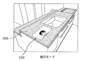
- FIG. 4B is a diagram for explaining a display mode in the display device according to the embodiment.
- FIG. 5 is a diagram for explaining the first experiment according to the embodiment.
- FIG. 6 is a diagram showing the characteristics of the film used in the first experiment according to the embodiment.
- FIG. 7 is a diagram showing the results of the first experiment according to the embodiment.
- FIG. 1 is an exploded perspective view schematically showing a schematic configuration of a display device according to an embodiment.
- FIG. 2 is a cross-sectional view schematically showing a cross-sectional configuration of the display
- FIG. 8 is a diagram for explaining a second experiment according to the embodiment.
- FIG. 9 is a diagram showing the results of the second experiment according to the embodiment.
- FIG. 10 is a flowchart showing a display method of the display device according to the embodiment.
- FIG. 11A is a diagram for explaining a non-display mode in application example 1 of the display device according to the embodiment.
- FIG. 11B is a diagram for explaining a display mode in application example 1 of the display device according to the embodiment.
- FIG. 12A is a diagram for explaining a non-display mode in Application 2 of the display device according to the embodiment.
- FIG. 12B is a diagram for explaining a display mode in application example 2 of the display device according to the embodiment.
- FIG. 13A is a diagram for explaining a non-display mode in Application 3 of the display device according to the embodiment.
- FIG. 13B is a diagram for explaining a display mode in application example 3 of the display device according to the embodiment.
- each figure is a schematic diagram and is not necessarily exactly illustrated. Further, in each figure, substantially the same configuration may be designated by the same reference numerals, and duplicate description may be omitted or simplified.
- the display device 100 is used by being attached to, for example, an object (for example, a wall).
- the display device 100 is, for example, an embedded display device embedded in an object.
- an example in which the object is a wood grain wall (see FIG. 11A and the like) will be described, but the object is not limited to this.
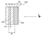
- FIG. 1 is an exploded perspective view schematically showing a schematic configuration of a display device 100 according to the present embodiment.
- FIG. 2 is a cross-sectional view schematically showing a cross-sectional configuration of the display device 100 according to the present embodiment.
- FIG. 3 is a block diagram showing a functional configuration of the display device 100 according to the present embodiment. Note that, in FIG. 1, among the components included in the display device 100, only the display unit 10, the decorative sheet 20, and the dimming sheet 30 are shown.
- the display device 100 includes a display unit 10, a decorative sheet 20, a dimming sheet 30, adhesive layers 40 and 41, and a control unit 50. Further, as shown in FIGS. 1 and 2, the display unit 10, the dimming sheet 30, and the decorative sheet 20 are arranged in this order. Specifically, the dimming sheet 30 and the decorative sheet 20 are arranged in this order on the display surface 10a side of the display unit 10.
- the display unit 10 may be embedded in the object. Further, being embedded means that at least the display unit 10 is located inside the object. Further, the display device 100 is embedded in the object so that the user can visually recognize the decorative sheet 20.
- the display unit 10 has a display surface 10a and displays an image on the display surface 10a.
- the display unit 10 is, for example, a liquid crystal display or an organic EL (Electro Luminescence) display, but is not limited thereto.
- the display unit 10 may be, for example, an LED (Light Emitting Diode) display or the like when it is desired to increase the brightness of the image displayed on the display device 100.
- the video includes a still image and a moving image.
- the decorative sheet 20 is provided to hide (conceal) the display device 100 in a state where the display device 100 is embedded in the object.
- the decorative sheet 20 has translucency and is arranged on the display surface 10a side of the display unit 10, and is decorated according to the appearance of the object.
- the decoration is applied to the entire surface of the decoration sheet 20, for example, but may be partially applied.
- the decorative sheet 20 is provided so as to cover both the display area 11 for displaying the image of the display unit 10 and the peripheral area 12 provided with ancillary elements such as a wiring pattern.
- the decoration applied to the decorative sheet 20 may be applied to both the display area 11 and the peripheral area 12, for example, or only one of the display area 11 and the peripheral area 12 (for example, the display area 11). Only) may be applied.
- the decorative sheet 20 may have different decorative patterns formed in the display area 11 and the peripheral area 12, for example.
- the appearance includes, for example, the pattern, color tone, gloss, and texture of the object. Further, the appearance may include the surface shape of the object.
- the display device 100 and the object can be seen integrally with the display device 100 in a state of being embedded in the object (for example, it is visible that the display device 100 is present). It should be decorated (hard to be done).
- the decoration applied to the decoration sheet 20 may be, for example, a decoration that harmonizes with the interior of the room where the object is installed. For example, when the object is a wall, when the display device 100 is embedded in the wall and the display unit 10 looks at the wall in a state where no image is displayed, the display device 100 is also embedded in the wall.
- the decoration should be visible. In the present embodiment, since the object is a wood grain wall, the decoration sheet 20 is decorated with the wood grain.
- the decorative sheet 20 is arranged, for example, in the foreground of the display device 100. With the display device 100 embedded in the object, the user visually recognizes the decorative sheet 20.
- the decorative sheet 20 has a base material 21 and a decorative layer 22.
- a plan view here, when viewed from the direction of the line of sight shown in FIG. 2 is about the same as that of the display unit 10 is shown.
- the decorative sheet 20 may be larger than the display unit 10 in a plan view, for example.
- the base material 21 is a layer that is the base of the decorative sheet 20, and is made of a translucent resin material or the like.
- the base material 21 may be transparent, for example.
- the base material 21 is made of, for example, PET (polyethylene terephthalate), PC (polycarbonate), PMMA (polymethylmethacrylate / acrylic resin), or the like.
- the base material 21 is, for example, a flat plate, but may have a shape corresponding to the surface shape of the object. For example, when the surface of the object has an uneven shape, the base material 21 may have the uneven shape.
- the decorative layer 22 is a decorative pattern layer formed of a material such as a transparent resin ink containing a pigment or a paint.
- the decorative layer 22 is formed by forming a decorative pattern on one side or both sides of the base material 21 by printing or the like using a material.
- the printing method is, for example, screen printing, but is not limited thereto.
- the decorative layer 22 has translucency.
- the decoration pattern constituting the decoration layer 22 is appropriately determined according to the appearance of the object in which the display device 100 is embedded.
- the decoration pattern may be, for example, the same color tone or pattern as the color tone or pattern of the object in which the display device 100 is embedded.
- the surface 20a of the decorative sheet 20 is arranged on the same surface as the surface of the object, for example. That is, the display device 100 may be mounted so as to be embedded in the object so that the decorative layer 22 is flush with the surface of the object.
- the decorative sheet 20 may be composed of any of a half mirror, a colored film, and colored glass.
- the half mirror is constructed, for example, by forming a metal film or a transparent laminated film on the base material 21.
- the metal film is formed by forming aluminum, silver, tin or the like by a vapor deposition method or the like.
- the base material 21 of the colored film and the colored glass is formed by kneading a pigment or dye into the base material or the like.
- the base material 21 of the colored film is made of resin, and the base material 21 of colored glass is made of glass.
- the decorative pattern may be formed by the base material 21 itself.
- the decorative layer 22 may be further formed on the base material 21 by printing or the like.
- the transmittance of the decorative sheet 20 can be set higher than that of the case where the display device 100 does not include the dimming sheet 30.
- the transmittance of the decorative sheet 20 is, for example, 20% to 50%, but is not limited thereto.
- the decorative layer 22 may be an uneven layer formed by embossing or the like, or may be a printed layer and an uneven layer, instead of a printing layer on which a decorative pattern is formed by printing or the like. At least one of the print layer and the uneven layer may be appropriately selected according to the appearance of the object to which the display device 100 is attached.
- the dimming sheet 30 is arranged between the display unit 10 and the decorative sheet 20 arranged in parallel with each other, and has a high transmittance state with high light transmittance and a low light transmittance state with lower light transmittance than the high transmittance state. Can be switched.
- the dimming sheet 30 is, for example, a pair of substrates, a pair of electrodes arranged between the pair of substrates, and a layer arranged between the pair of electrodes, and is a physical stimulus such as a voltage. It may be configured to have a state change layer whose state changes depending on the situation. Then, the light control sheet 30 may switch between a high transmission state and a low transmission state by changing the state of the state change layer by the voltage applied to the pair of electrodes.
- the dimming sheet 30 is a dimming sheet using a PDLC (Polymer Disperseed Liquid Crystal) method.
- the dimming sheet 30 is composed of a polymer network type liquid crystal display.
- the light control sheet 30 has a pair of substrates, a pair of electrodes arranged between the pair of substrates, and a liquid crystal layer (an example of a state change layer) sandwiched between the pair of electrodes.
- a network structure made of a special polymer is formed on the liquid crystal layer. Due to the action of the polymer network, the light control sheet 30 induces an irregular arrangement of liquid crystal molecules to scatter light. Then, when the liquid crystal molecules are arranged in the electric field direction by applying a voltage, the light is not scattered and is transmitted. In this way, the light control sheet 30 can switch between a light diffusing state and a light transmitting state by applying a voltage.
- the light diffusion state is a state in which the light control sheet 30 becomes milky white and diffuses the incident light.
- the parallel light transmittance is lower than that in the light transmitting state.
- the light diffusion state is a state in which the parallel light transmittance is lower than that in the light transmission state, and is an example of the low transmission state.
- the light transmission state is a state in which the light control sheet 30 becomes transparent and transmits the incident light.
- the parallel light transmittance is higher than that in the light diffusion state.
- the light diffusion state is a state in which the parallel light transmittance is higher than that in the light transmission state, and is an example of the high transmission state.
- the parallel light transmittance of the light control sheet 30 in the light diffusion state is less than 50%, for example, 25%. Further, the parallel light transmittance of the light control sheet 30 in the light transmitting state (high transmitting state) is 50% or more, for example, about 60%. The value of the parallel light transmittance is not limited to this.
- the dimming sheet 30 is not limited to the above configuration, and may be a display capable of switching between a light transmission state (an example of a high transmission state) and a non-light transmission state (an example of a low transmission state). That is, the light control sheet 30 may have a configuration in which the transmittance (for example, the total light transmittance) can be changed.
- the dimming sheet 30 may be a display using an SPD (Suspended Particulate Device) method or an EC (Electro Chromic) method.
- SPD Small Particulate Device
- EC Electro Chromic
- the light control sheet 30 using the EC method has a structure in which a light control layer (electrolyte layer) is sandwiched between a pair of electrodes. Depending on the potential difference between the electrodes, the color of the light control layer changes between transparent and navy blue using the redox reaction.
- a state in which the total light transmittance is high is an example of a high transmittance state
- a state in which the total light transmittance is low is an example of a low transmission state.
- the adhesive layer 40 is an adhesive member for bonding the display unit 10 and the dimming sheet 30.
- the adhesive layer 41 is an adhesive member for bonding the dimming sheet 30 and the decorative sheet 20.
- the adhesive layers 40 and 41 are made of highly transparent adhesive members such as OCA (Optical Clear Adhesive). Further, as the adhesive layers 40 and 41, those having a refractive index close to that of the transparent substrate of the display unit 10 and the light control sheet 30 may be selected.
- the thickness of the adhesive layer 40 corresponds to the distance d1 between the display unit 10 and the dimming sheet 30.
- the thickness of the adhesive layer 41 corresponds to the distance between the light control sheet 30 and the decorative sheet 20.
- the total thickness of the adhesive layer 40, the light control sheet 30, and the adhesive layer 41 corresponds to the distance d2 between the display unit 10 and the decorative sheet 20.
- direct bonding means that the adhesive layer 40 is bonded to the display unit 10 without including any components other than the adhesive layer 40.
- the adhesive layer 40 may not be provided when one of the display unit 10 and the light control sheet 30 has an adhesive layer. Further, when one of the dimming sheet 30 and the decorative sheet 20 has an adhesive layer, the adhesive layer 41 may not be provided.
- the adhesive layers 40 and 41 may not be provided.
- the adhesive layers 40 and 41 may not be provided.
- the adhesive layers 40 and 41 may not be provided.
- at least one of the display unit 10, the dimming sheet 30, and the dimming sheet 30 and the decorative sheet 20 may be arranged in direct contact with each other.
- the control unit 50 is a control device that controls each component included in the display device 100. Specifically, the control unit 50 controls the display unit 10 and the dimming sheet 30 so that the user can see the decoration of the decoration sheet 20 without displaying the image on the display unit 10. The mode is switched between the display mode in which the image is displayed on the display unit 10.
- the control unit 50 has, for example, a reception unit (not shown) that accepts user operations, and may perform the above control according to the user operations acquired through the reception unit.
- control unit 50 is a microcomputer, it may be realized by a dedicated circuit or the like.
- the control unit 50 reads a control program from the built-in storage unit and executes the read program.
- the brightness value of the image displayed on the display device 100 configured as described above includes the brightness value of the image on the display unit 10 and the transmittance (for example, parallel light transmittance) in the high transmittance state of the dimming sheet 30. , It is determined according to the transmittance of the decorative sheet 20 (for example, the parallel light transmittance).
- the brightness value of the image displayed by the display device 100 is preferably 100 nits or more. In other words, the transmittance of the decorative sheet 20 and the dimming sheet 30 in the high transmissive state is determined so that the brightness value of the image displayed on the display device 100 is 100 nit or more, and is emitted from the display unit 10.
- the brightness value of light (image) is determined.
- the brightness value is, but is not limited to, the maximum value of the brightness in the image displayed by the display device 100.
- the brightness value may be a statistical value such as a minimum value, an average value, or a median value of an image displayed by the display device 100.
- FIG. 1 shows an example in which the display unit 10, the decorative sheet 20, and the dimming sheet 30 have a rectangular shape, but the shapes thereof are not limited to the rectangular shape. For example, it may have a polygonal shape or a circular shape. Further, FIG. 1 shows an example in which the display unit 10, the decorative sheet 20, and the dimming sheet 30 have the same size (size in a plan view), but the size is not limited to this.
- FIG. 4A is a diagram for explaining a non-display mode in the display device 100 according to the present embodiment.
- FIG. 4B is a diagram for explaining a display mode in the display device 100 according to the present embodiment.
- the non-display mode is a mode in which the display device 100 does not display an image.
- the user will visually recognize the decoration applied to the decoration sheet 20.
- the non-display mode the user visually recognizes the same wood grain pattern as the pattern on the wall in which the display device 100 is embedded. In other words, in the non-display mode, the user can see the wall and the display device 100 integrally.
- the display device 100 since the display device 100 is embedded, it is possible to reduce the discomfort caused by the display device 100 in the object or the space in which the object is arranged. In other words, it is possible to suppress the display device 100 from becoming spatial noise when the image is not displayed.
- the display unit 10 does not display an image (does not emit light) in the non-display mode, but may display an image having a brightness value equal to or less than a predetermined value, for example. For example, the display unit 10 may display an image darker than the display mode. Further, the dimming sheet 30 is in a low transmission state in the non-display mode. By arranging the light control sheet 30 in a low transmittance state, it is possible to suppress the display unit 10 from being visually recognized and to increase the transmittance of the decorative sheet 20 (for example, 20%). it can.
- the display mode is a mode in which the display device 100 displays an image. In this case, the user will visually recognize the image by the light emitted from the display unit 10. In display mode, the user appears to have an image displayed on the wall.
- the display unit 10 displays a brighter image in the display mode than in the non-display mode.
- the dimming sheet 30 is in a highly transmissive state. By arranging the dimming sheet 30 in a high transmission state, it is possible to suppress a decrease in the brightness of the image due to the arrangement of the dimming sheet 30. That is, by arranging the dimming sheet 30, it is possible to suppress deterioration of the image quality of the image.
- the decoration of the decoration layer 22 should not be visually recognized when operating in the display mode. Therefore, it is preferable to adjust the density of the decorative layer 22 so that the decorative layer 22 is not visually recognized in the display mode.
- FIG. 5 is a diagram for explaining the first experiment according to the present embodiment.
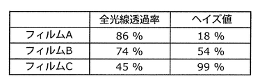
- FIG. 6 is a diagram showing the characteristics of the film 60 used in the first experiment according to the present embodiment.
- the display unit 10 and the film 60 are used.
- the display unit 10 displays a target image (“A” in the example of FIG. 5).
- the film 60 is a film assuming a decorative sheet 20 and a dimming sheet 30 in a highly transmissive state.
- the display unit 10 displays the character "A" in a negative display (display of white characters on a black background)
- the distance d between the display unit 10 and the film 60 is changed to determine whether or not the character is readable. went.
- the distance d is varied within the range of 0-10 mm.
- the character size is font 8 and the font is MS Mincho. Readability is determined by visual evaluation (subjective evaluation) by the subject. Further, as shown in FIG. 6, experiments are conducted using three types of films A to C having different total light transmittances and haze values.
- the three types of films 60 are produced, for example, by screen-printing a transparent resin ink containing a pigment on a PET (Polyethylene terephthalate) film having a thickness of 50 ⁇ m.
- the environment of the first experiment is conducted in a room where fluorescent lights are lit.
- the display unit 10 is a 31-inch liquid crystal display having a resolution of 4K (4096 pixels x 2160 pixels).
- the output of the backlight is adjusted so that the brightness of the image (“A”) displayed by the display unit 10 is 200 to 250 nits.
- An air layer is formed between the display unit 10 and the film 60.
- the subject confirms the characters at a position 0.5 m from the display unit 10 to determine whether or not the characters are readable.
- FIG. 7 is a diagram showing the results of the first experiment according to the present embodiment.
- “ ⁇ ” shown in FIG. 7 means that the readability is high (characters are easy to read).
- “ ⁇ ” means that the readability is low (it is difficult to read but can be discriminated).
- " ⁇ ” and “ ⁇ ” mean that they are readable.
- "X” means that it is unreadable (unidentifiable).
- the film A haze value 18%) and the film B (haze value 54%) are readable in a distance d in the range of 0 to 10 mm. Further, if the film C (haze value is 99%), the film C is readable in a distance d in the range of 0 to 0.5 mm.
- the haze value of the decorative sheet 20 and the light control sheet 30 in the high transmission state is less than 55%, respectively.
- the haze value of the decorative sheet 20 and the light control sheet 30 in the high transmission state may be 10% or more and less than 55%, respectively.
- the distance d1 and the distance d2 are not particularly limited as long as they are within the range of 10 mm or less.
- the haze value of at least one of the decorative sheet 20 and the highly transmissive dimming sheet 30 is 55% or more, and the distance between the at least one and the display unit 10 is 0.5 mm or less.
- the haze value of the dimming sheet 30 in the high transmission state is 55% or more, and the distance between the dimming sheet 30 and the display unit 10 is preferably 0 mm. ..
- the distance of 0 mm means that the light control sheet 30 and the display unit 10 are directly bonded to each other by the adhesive layer of one of the light control sheet 30 and the display unit 10 without passing through the adhesive layer 40. ..
- the distance d1 between the light control sheet 30 and the display unit 10 is , 0.5 mm or less.
- the thickness of the adhesive layer 40 is preferably 0.5 mm or less.
- the haze value of the decorative sheet 20 is 55% or more
- the distance d2 between the decorative sheet 20 and the display unit 10 is preferably 0.5 mm or less.
- the total thickness of the adhesive layer 40, the light control sheet 30, and the adhesive layer 41 is preferably 0.5 mm or less.
- FIG. 8 is a diagram for explaining a second experiment according to the present embodiment.
- the display unit 10 and the film 60 are used.
- the display unit 10 displays a target image (white line pattern in the example of FIG. 8).
- the width of the white line pattern (length in the lateral direction) is 7 mm.
- the film 60 the same film used in the first experiment is used.
- the display unit 10 displays the white line pattern in negative display (display of the white line pattern on a black background)
- the distance d between the display unit 10 and the film 60 is changed to change the edge of the white line pattern (white line). It was determined whether or not the pattern (the boundary between the pattern and the black background) was blurred.
- the distance d is varied within the range of 0 to 4.0 mm. Whether or not the bleeding is within the permissible range is determined by visual evaluation (subjective evaluation) by the subject.
- the environment of the second experiment is the same as that of the first experiment.
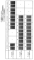
- FIG. 9 is a diagram showing the results of the second experiment according to the present embodiment.
- “ ⁇ ” shown in FIG. 9 means substantially no bleeding.
- “ ⁇ ” means that there is slight bleeding (within the allowable range).
- “ ⁇ ” and “ ⁇ ” mean that the blur of the image is within the permissible range.
- “X” means that there is bleeding (outside the allowable range).
- the haze value of at least one of the decorative sheet 20 and the dimming sheet 30 in the high transmission state is 20% or more and less than 55%, and at least one of them and the display unit 10
- the distance to and from is preferably 1.0 mm or less.
- the distance between at least one of them and the display unit 10 is preferably 0.5 mm or less.
- the distance between the dimming sheet 30 and the display unit 10 which is at least one of them is preferably 0 mm.
- the haze value of at least one of the decorative sheet 20 and the dimming sheet 30 in the high transmission state is less than 20%, and the distance between the at least one and the display unit 10 Is preferably 4.0 mm or less.
- the distance between the at least one and the display unit 10 is 4.0 mm or less. You may.
- the distance between at least one of them and the display unit 10 is preferably 3.0 mm or less.
- the haze value of at least one of the decorative sheet 20 and the dimming sheet 30 in the high transmission state is 55% or more, and the distance between the at least one and the display unit 10 is 0.5 mm or less. May be good.
- the distance between the light control sheet 30 and the display unit 10 is 1.0 mm or less, and the distance d2 between the decorative sheet 20 and the display unit 10 is 4.0 mm or less.
- the thickness of the adhesive layer 40 is 1.0 mm or less, and the total thickness of the adhesive layer 40, the light control sheet 30 and the adhesive layer 41 is 4.0 mm or less.
- the haze value of the decorative sheet 20 and the dimming sheet 30 is 20% or more and less than 55%, and the distance d2 between the decorative sheet 20 and the display unit 10 is 1.0 mm or less. May be good.
- the total thickness of the adhesive layer 40, the light control sheet 30, and the adhesive layer 41 is preferably 1.0 mm or less.
- the display device 100 can display a high-quality image equivalent to, for example, a television device.
- the haze values of the decorative layer 22 and the light control sheet 30 in the high transmission state are preferably less than 20%, respectively. Further, from the viewpoint of further suppressing the occurrence of image blur, the haze values of the decorative sheet 20 and the light control sheet 30 in the high transmission state are preferably 10% or less, respectively.
- Such a decorative sheet 20 may be realized by being composed of any of a half mirror, a colored film, and colored glass.
- the inside of the display device 100 or the object may be visible due to external light. Therefore, in the display mode, from the viewpoint of reducing the influence of external light on the appearance of the display device 100, the decorative layer 22 and the light control sheet 30 in the high transmission state are within a range in which there is substantially no influence on the image. It is good to have a haze value. Further, when the display device 100 operates in the non-display mode, the display device 100 looks glossy when the haze value is low. For example, when the haze value of the light control sheet 30 in the low transmission state is low, the display device 100 appears to be glossier than the object.
- the decorative layer 22 and the dimming sheet 30 in the low transmission state can obtain the same gloss as the object from the viewpoint of reducing the influence of external light on the appearance of the display device 100. It is good to have a haze value.
- the light control sheet 30 has a different haze value between the high transmission state and the low transmission state. The haze value is higher in the low transmission state than in the high transmission state.
- FIG. 10 is a flowchart showing a display method of the display device 100 according to the present embodiment. Specifically, FIG. 10 shows a control method by the control unit 50.
- the control unit 50 determines whether or not to display an image (S10).
- the control unit 50 determines in step S10, for example, depending on whether or not an operation for displaying an image is acquired from the user or an operation for stopping the display of an image is acquired. Further, the control unit 50 receives information indicating that the user is in front of the display unit 10 from a sensor (not shown, for example, a motion sensor) that detects whether or not the user is in front of the display unit 10. Once acquired, it may be determined that the image is displayed. Further, the control unit 50 may determine that the video is displayed when the control unit 50 acquires information indicating that the user has made an utterance to display the display unit 10 from a microphone or the like that acquires the user's voice.
- control unit 50 causes the user to display the display unit 10 from a sensor that detects the user's movement (not shown, for example, a camera that detects the distance by a stereo camera, TOF (Time Of Flight), or the like).
- a sensor that detects the user's movement not shown, for example, a camera that detects the distance by a stereo camera, TOF (Time Of Flight), or the like.
- TOF Time Of Flight
- the sensor, microphone, and the like may be provided in the display device 100, or may be provided in a device outside the display device 100, and the display device 100 may provide the above information by communication (for example, wireless communication). You may get it.
- the display device 100 allows the user to display the display unit 10 from a voice acquisition device (for example, a smart speaker (AI speaker) or a smartphone) including a microphone or the like. Information indicating that an utterance indicating that the operation is performed may be acquired. Further, to explain the case of acquiring the information on the user's movement, the information on the user's movement is acquired from the wearable terminal worn by the user and having the motion sensor for detecting the user's movement. May be good.
- a voice acquisition device for example, a smart speaker (AI speaker) or a smartphone
- Information indicating that an utterance indicating that the operation is performed may be acquired.
- the information on the user's movement is acquired from the wearable terminal worn by the user and having the motion sensor for detecting the user's movement. May
- control unit 50 when the control unit 50 acquires an operation to display an image from the user, it determines that the image is to be displayed (Yes in S10), and controls the display unit 10 and the dimming sheet 30 to the display mode (S20). Specifically, the control unit 50 starts displaying an image by turning on the display unit 10, and puts the dimming sheet 30 in a high transmission state (in the present embodiment, a light transmission state). More specifically, the control unit 50 starts supplying electric power and video data to the display unit 10, for example. Further, the control unit 50 shifts the dimming sheet 30 from the low transmission state to the high transmission state by starting the application of the voltage to the light control sheet 30.
- control unit 50 when the control unit 50 acquires an operation to stop the image from the user, it determines that the image is not displayed (No in S10), and controls the display unit 10 and the dimming sheet 30 to the non-display mode (No). S30). Specifically, the control unit 50 stops the display of the image by turning off the display unit 10, and puts the dimming sheet 30 in a low transmission state (in the present embodiment, a light diffusion state). More specifically, the control unit 50 stops the supply of electric power and video data to the display unit 10, for example. Further, the control unit 50 shifts the dimming sheet 30 from the high transmission state to the low transmission state by stopping the application of the voltage to the light control sheet 30.
- the control unit 50 puts the dimming sheet 30 in a high transmission state when the display unit 10 is displaying an image, and makes the dimming sheet 30 low transmission when the display unit 10 is not displaying an image. Make it a state.
- the control unit 50 changes the states of both the display unit 10 and the dimming sheet 30 when transitioning from one of the display mode and the non-display mode to the other. For example, when switching from the display mode to the non-display mode, the control unit 50 not only stops the output of the image by the display unit 10 (an example of changing the state of the display unit 10), but also reduces the light control sheet 30. Decrease the transmittance (an example of changing the state of the dimming sheet 30).
- step shown in FIG. 10 is repeatedly executed. Then, according to the determination in step S10, the transition from one of the display mode and the non-display mode to the other, or the maintenance of the mode before the determination is repeatedly performed.
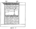
- FIG. 11A is a diagram for explaining a non-display mode in application example 1 of the display device 100 according to the present embodiment.
- FIG. 11B is a diagram for explaining a display mode in application example 1 of the display device 100 according to the present embodiment.
- the display device 100 may be housed and installed in a construction material (for example, a wall 200) which is an example of an object.
- the construction material includes a main body having a recess for accommodating the display device 100, and a display device 100 housed in the recess.
- the recess is a recess for embedding the display device 100 in the construction material.
- the wall 200 has, for example, a wood grain pattern.
- the decorative sheet 20 is decorated with wood grain.
- Wood grain decoration is an example of decoration according to the object.
- the control unit 50 controls the display unit 10 and the dimming sheet 30 in the non-display mode
- the user visually recognizes the wood grain decoration formed on the decoration sheet 20. Will be done. That is, the appearance of the display device 100 is in harmony with the appearance of the wall 200. As a result, it is difficult to visually recognize that the display device 100 is embedded in the wall 200.
- the decorative sheet 20 can prevent the display device 100 from being visible.
- the control unit 50 controls the display unit 10 and the dimming sheet 30 in the display mode
- the user can visually recognize the image displayed by the display unit 10.
- the user can, for example, visually recognize an image that appears to be floating on the wall 200.
- it is preferable that the decoration formed on the decoration sheet 20 is not visually recognized by the user.
- FIG. 12A is a diagram for explaining a non-display mode in application example 2 of the display device 100 according to the present embodiment.
- FIG. 12B is a diagram for explaining a display mode in application example 2 of the display device 100 according to the present embodiment.
- the display device 100 may be housed and installed in furniture (for example, a kitchen stand 300) which is an example of an object.
- the furniture includes a main body having a recess for accommodating the display device 100, and a display device 100 housed in the recess.
- the recess is a recess for embedding the display device 100 in furniture.
- the kitchen stand 300 has, for example, a marble-like pattern.
- the decorative sheet 20 is decorated in a marble-like manner.
- Marble-like decoration is an example of decoration according to the object.
- the control unit 50 controls the display unit 10 and the dimming sheet 30 in the non-display mode
- the user visually recognizes the marble-like decoration formed on the decoration sheet 20. Will be done. That is, the appearance of the display device 100 is in harmony with the appearance of the kitchen table 300. As a result, it is difficult to visually recognize that the display device 100 is embedded in the kitchen table 300.
- the control unit 50 controls the display unit 10 and the dimming sheet 30 in the display mode
- the user can visually recognize the image displayed by the display unit 10.
- the user can, for example, visually recognize an image that appears to be floating on the kitchen table 300.
- the user can check the state of the child while cooking.
- FIG. 13A is a diagram for explaining a non-display mode in application example 3 of the display device 100 according to the present embodiment.
- FIG. 13B is a diagram for explaining a display mode in application example 3 of the display device 100 according to the present embodiment.
- the display device 100 may be housed and installed in an electric device (for example, a household electric device such as a refrigerator 400) which is an example of an object.
- the electric device includes a main body having a recess for accommodating the display device 100, and a display device 100 housed in the recess.
- the recess is a recess for embedding the display device 100 in an electric device.
- the refrigerator 400 has, for example, a single color (for example, white).
- the decorative sheet 20 is given a white color tone.
- the white decoration is an example of decoration according to the object.
- the control unit 50 controls the display unit 10 and the dimming sheet 30 in the non-display mode
- the user visually recognizes the white decoration formed on the decoration sheet 20. It will be. That is, the appearance of the display device 100 is in harmony with the appearance of the refrigerator 400. As a result, it is difficult to visually recognize that the display device 100 is embedded in the refrigerator 400.
- the control unit 50 controls the display unit 10 and the dimming sheet 30 in the display mode
- the user can visually recognize the image displayed by the display unit 10.
- the user can visually recognize an image that appears to be floating in the refrigerator 400.
- the user can efficiently cook.
- the display device 100 is a display device 100 attached to an object, has a display surface 10a, and has a display unit 10 for displaying an image on the display surface 10a and a transparent unit 10.
- the decorative layer 22 which has light property and is arranged on the display surface 10a side of the display unit 10 and is decorated according to the appearance of the object, and the display unit 10 and the addition.
- the light control sheet 30 is arranged between the decorative layer 22 and includes a light control sheet 30 capable of switching between a high transmission state and a low transmission state having a lower light transmittance than the high transmission state.
- the transmittance of the decorative sheet 20 can be increased as compared with the case where the display device 100 does not include the dimming sheet 30. That is, the display device 100 can display a brighter image than when the dimming sheet 30 is not provided. Further, since the dimming sheet 30 is in a low transmission state when the display unit 10 is not displaying an image, the display unit 10 and the like are compared with the case where the display device 100 does not have the dimming sheet 30. It is possible to suppress the invisible. That is, by providing the dimming sheet 30, the display device 100 can improve the image quality of the image displayed by the display unit 10 and hide the display unit 10 and the like when the display unit 10 does not display the image. it can.
- the decoration sheet 20 is decorated according to the appearance of the object, the user can see the decoration of the decoration sheet 20 when the display unit 10 is not displaying the image. Become. That is, the display device 100 is in a state of being blended into the object and the space in which the object is installed.
- the display device 100 it is possible to suppress the display unit 10 from being visually recognized when the image is not displayed, and also to suppress the deterioration of the image quality of the displayed image.
- the haze value of at least one of the decorative sheet 20 and the dimming sheet 30 in the high transmission state is 55% or more, and the distance between the at least one and the display unit 10 is 0.5 mm or less.
- the haze value is 55% or more, it is possible to display a high-quality image with less blur and a readable image. Further, when the haze value is 55% or more, it is possible to prevent the display unit 10 and the like from being seen by the external light incident from the decorative sheet 20 when the display device 100 is not displaying the image. it can.
- the haze value of at least one of the decorative sheet 20 and the highly transmissive dimming sheet 30 is 20% or more and less than 55%, and the distance between the at least one and the display unit 10 is 1 mm or less. ..
- the display device 100 can determine the distance d1 or the distance d2 in the range of 1 mm or less, the degree of freedom in the thickness of each component is increased. Therefore, according to this configuration, it is possible to suppress blurring of the image and improve the degree of freedom in designing the thickness of each component.
- the haze value of at least one of the decorative sheet 20 and the dimming sheet 30 in the high transmission state is less than 20%, and the distance between the at least one and the display unit 10 is 4 mm or less.
- the display device 100 can determine the distance d1 or the distance d2 in the range of 4 mm or less, the degree of freedom in the thickness of each component is further increased. Therefore, according to this configuration, it is possible to further improve the degree of freedom in the thickness of each component while suppressing the blurring of the image.
- the other members may be appropriately determined depending on the object in which the display device 100 is embedded, the usage environment, and the like.
- the other member may be a heat-resistant sheet having translucency, or a translucent sheet that accepts an operation from the user. It may be a touch film having a property.
- the haze value of the decorative sheet 20 and the light control sheet 30 in the high transmission state is less than 55%, respectively.
- a readable image can be displayed.
- a readable image can be displayed even when the display unit 10 is separated from the decorative sheet 20 and the dimming sheet 30 in a highly transmissive state (for example, within a range of 10 mm). it can.
- the haze value of the decorative sheet 20 and the light control sheet 30 in the high transmission state is 10% or less, respectively.
- the display device 100 when the display device 100 is displaying an image, it is possible to further prevent the image from being blurred by the decorative sheet 20 and the dimming sheet 30.
- the decorative sheet 20 is composed of any one of a half mirror, a colored film, and colored glass.
- the haze value of the decorative sheet 20 can be lowered. That is, the decorative sheet 20 suppresses deterioration of the image quality of the image (for example, blurring of the image). Therefore, it is possible to arrange other members for improving the function of the display device 100 between the decorative sheet 20 and the display unit 10 and in front of the decorative sheet 20.
- the other member may be, for example, a heat-resistant sheet having translucency.
- the brightness value of the image transmitted through the decorative sheet 20 is 100 nits or more.
- the display device 100 can display a bright image of 100 nits or more. Therefore, the quality of the image is further improved.
- the display device 100 may include a display unit 10, a dimming sheet 30, and a decorative layer 22.
- the decorative layer 22 may be provided on the light control sheet 30, for example.
- the decorative layer 22 is formed on the base material arranged on the surface side of the display device 100 among the pair of base materials included in the light control sheet 30.
- the dimming sheet 30 is in a high transmission state when a voltage is applied, and is in a low transmission state when the voltage application is stopped, but the present invention is not limited to this.
- the dimming sheet 30 may be configured to be in a low transmission state when a voltage is applied, and to be in a high transmission response when the voltage application is stopped.
- the distance d2 is the distance from the display unit 10 to the decorative sheet 20
- the distance d2 is not limited to this.
- the distance d2 is defined as the distance from the display unit 10 to the decorative layer 22.
- the display device 100 is not limited to being embedded and arranged.
- the display device 100 may be fixed to the surface of the object.
- the display device 100 may be attached to the surface of the object.
- the image displayed by the display unit 10 in the above embodiment is not particularly limited, and may be a television image (for example, 4K television image quality), or may be displayed as an icon or a segment (for example, 7-segment display). There may be.
- This disclosure is applicable to a display device attached to an object.
- Display unit 10 Display unit 10a Display surface 11 Display area 12 Peripheral area 20 Decorative sheet 20a Surface 21 Base material 22 Decorative layer 30 Dimming sheet 40, 41 Adhesive layer 50 Control unit 60 Film 100 Display device 200 Wall (object) 300 kitchen stand (object) 400 Refrigerator (object) d, d1, d2 distance
Landscapes
- Physics & Mathematics (AREA)
- General Physics & Mathematics (AREA)
- Nonlinear Science (AREA)
- Optics & Photonics (AREA)
- Chemical & Material Sciences (AREA)
- Crystallography & Structural Chemistry (AREA)
- Mathematical Physics (AREA)
- Engineering & Computer Science (AREA)
- Theoretical Computer Science (AREA)
- Devices For Indicating Variable Information By Combining Individual Elements (AREA)
- Liquid Crystal (AREA)
- Optical Elements Other Than Lenses (AREA)
Abstract
L'invention concerne un dispositif d'affichage (100) qui est un dispositif d'affichage (100) qui est fixé à un article cible, et qui comprend : une unité d'affichage (10) qui a une surface d'affichage (10a) et qui affiche une vidéo sur la surface d'affichage (10a) ; une feuille décorative (20) qui est translucide et qui est positionnée du côté de la surface d'affichage (10a) de l'unité d'affichage (10), ladite feuille décorative (20) comportant une décoration qui est fonction de l'apparence externe de l'article cible ; et une feuille de gradation de lumière (30) qui est positionnée entre l'unité d'affichage (10) et la feuille décorative (20), ladite feuille de gradation de lumière (30) pouvant commuter entre un état à haute transmittance et un état à basse transmittance dans lequel la transmittance de lumière est inférieure à celle de l'état à haute transmittance.
Priority Applications (2)
| Application Number | Priority Date | Filing Date | Title |
|---|---|---|---|
| JP2021508687A JP7281652B2 (ja) | 2019-03-28 | 2019-08-27 | 表示装置 |
| CN201990001356.3U CN216119294U (zh) | 2019-03-28 | 2019-08-27 | 显示装置 |
Applications Claiming Priority (2)
| Application Number | Priority Date | Filing Date | Title |
|---|---|---|---|
| JP2019-064056 | 2019-03-28 | ||
| JP2019064056 | 2019-03-28 |
Publications (1)
| Publication Number | Publication Date |
|---|---|
| WO2020194784A1 true WO2020194784A1 (fr) | 2020-10-01 |
Family
ID=72610455
Family Applications (1)
| Application Number | Title | Priority Date | Filing Date |
|---|---|---|---|
| PCT/JP2019/033508 Ceased WO2020194784A1 (fr) | 2019-03-28 | 2019-08-27 | Dispositif d'affichage |
Country Status (3)
| Country | Link |
|---|---|
| JP (1) | JP7281652B2 (fr) |
| CN (1) | CN216119294U (fr) |
| WO (1) | WO2020194784A1 (fr) |
Cited By (8)
| Publication number | Priority date | Publication date | Assignee | Title |
|---|---|---|---|---|
| JP2021162723A (ja) * | 2020-03-31 | 2021-10-11 | 凸版印刷株式会社 | 表示装置 |
| WO2022124279A1 (fr) * | 2020-12-07 | 2022-06-16 | 大日本印刷株式会社 | Feuille décorative et dispositif d'affichage |
| WO2022181406A1 (fr) * | 2021-02-25 | 2022-09-01 | 日東電工株式会社 | Film décoratif |
| JP2023063064A (ja) * | 2021-10-22 | 2023-05-09 | 凸版印刷株式会社 | 表示システム |
| WO2023163192A1 (fr) * | 2022-02-25 | 2023-08-31 | 大日本印刷株式会社 | Feuille décorative, élément décoratif, système d'affichage, procédé de fabrication de plaque, procédé de fabrication de feuille décorative et procédé de fabrication d'élément décoratif |
| JP2024047457A (ja) * | 2022-09-26 | 2024-04-05 | Agc株式会社 | ガラス振動板、振動子付きガラス振動板及びガラス振動板の製造方法 |
| JP2024158933A (ja) * | 2023-04-28 | 2024-11-08 | Kepler株式会社 | 表示装置、電子機器 |
| US12614530B2 (en) | 2022-05-23 | 2026-04-28 | Panasonic Intellectual Property Management Co., Ltd. | Display member |
Families Citing this family (1)
| Publication number | Priority date | Publication date | Assignee | Title |
|---|---|---|---|---|
| JP7720027B2 (ja) * | 2020-05-14 | 2025-08-07 | 大日本印刷株式会社 | 加飾シート及び加飾シート付き表示装置 |
Citations (9)
| Publication number | Priority date | Publication date | Assignee | Title |
|---|---|---|---|---|
| WO2009008402A1 (fr) * | 2007-07-11 | 2009-01-15 | Nissha Printing Co., Ltd. | Plaque de protection de dispositif d'affichage pour appareil électronique, et appareil électronique |
| JP2010237436A (ja) * | 2009-03-31 | 2010-10-21 | Nissha Printing Co Ltd | 機器用隠蔽フィルム、それを使用する機器、及び、機器の被隠蔽部の隠蔽方法 |
| JP2014503379A (ja) * | 2010-11-12 | 2014-02-13 | ヴァーサタイル テクノロジーズ リミテッド | 化粧パネル |
| JP2015184471A (ja) * | 2014-03-24 | 2015-10-22 | 大日本印刷株式会社 | 表示装置 |
| JP2015206934A (ja) * | 2014-04-22 | 2015-11-19 | 大日本印刷株式会社 | 画像表示装置 |
| JP2016035519A (ja) * | 2014-08-04 | 2016-03-17 | パナソニックIpマネジメント株式会社 | パネルユニット、ガラスパネル及びパネル材 |
| WO2016136102A1 (fr) * | 2015-02-26 | 2016-09-01 | ソニー株式会社 | Dispositif électronique |
| WO2016152792A1 (fr) * | 2015-03-23 | 2016-09-29 | コニカミノルタ株式会社 | Module de panneau électroluminescent organique |
| US20180370183A1 (en) * | 2017-06-23 | 2018-12-27 | Samsung Display Co., Ltd. | Decorative print member and display device including the same |
Family Cites Families (1)
| Publication number | Priority date | Publication date | Assignee | Title |
|---|---|---|---|---|
| KR102058456B1 (ko) | 2015-08-31 | 2019-12-23 | 삼성전자주식회사 | 디스플레이 장치 및 이를 포함하는 가전기기 |
-
2019
- 2019-08-27 CN CN201990001356.3U patent/CN216119294U/zh not_active Expired - Fee Related
- 2019-08-27 JP JP2021508687A patent/JP7281652B2/ja active Active
- 2019-08-27 WO PCT/JP2019/033508 patent/WO2020194784A1/fr not_active Ceased
Patent Citations (9)
| Publication number | Priority date | Publication date | Assignee | Title |
|---|---|---|---|---|
| WO2009008402A1 (fr) * | 2007-07-11 | 2009-01-15 | Nissha Printing Co., Ltd. | Plaque de protection de dispositif d'affichage pour appareil électronique, et appareil électronique |
| JP2010237436A (ja) * | 2009-03-31 | 2010-10-21 | Nissha Printing Co Ltd | 機器用隠蔽フィルム、それを使用する機器、及び、機器の被隠蔽部の隠蔽方法 |
| JP2014503379A (ja) * | 2010-11-12 | 2014-02-13 | ヴァーサタイル テクノロジーズ リミテッド | 化粧パネル |
| JP2015184471A (ja) * | 2014-03-24 | 2015-10-22 | 大日本印刷株式会社 | 表示装置 |
| JP2015206934A (ja) * | 2014-04-22 | 2015-11-19 | 大日本印刷株式会社 | 画像表示装置 |
| JP2016035519A (ja) * | 2014-08-04 | 2016-03-17 | パナソニックIpマネジメント株式会社 | パネルユニット、ガラスパネル及びパネル材 |
| WO2016136102A1 (fr) * | 2015-02-26 | 2016-09-01 | ソニー株式会社 | Dispositif électronique |
| WO2016152792A1 (fr) * | 2015-03-23 | 2016-09-29 | コニカミノルタ株式会社 | Module de panneau électroluminescent organique |
| US20180370183A1 (en) * | 2017-06-23 | 2018-12-27 | Samsung Display Co., Ltd. | Decorative print member and display device including the same |
Cited By (16)
| Publication number | Priority date | Publication date | Assignee | Title |
|---|---|---|---|---|
| JP7516819B2 (ja) | 2020-03-31 | 2024-07-17 | Toppanホールディングス株式会社 | 表示装置 |
| JP2021162723A (ja) * | 2020-03-31 | 2021-10-11 | 凸版印刷株式会社 | 表示装置 |
| JP7178004B2 (ja) | 2020-12-07 | 2022-11-25 | 大日本印刷株式会社 | 加飾シート、表示装置 |
| WO2022124279A1 (fr) * | 2020-12-07 | 2022-06-16 | 大日本印刷株式会社 | Feuille décorative et dispositif d'affichage |
| JP2022090637A (ja) * | 2020-12-07 | 2022-06-17 | 大日本印刷株式会社 | 加飾シート、表示装置 |
| CN116888526A (zh) * | 2021-02-25 | 2023-10-13 | 日东电工株式会社 | 装饰膜 |
| JP2022129507A (ja) * | 2021-02-25 | 2022-09-06 | 日東電工株式会社 | 加飾フィルム |
| WO2022181406A1 (fr) * | 2021-02-25 | 2022-09-01 | 日東電工株式会社 | Film décoratif |
| EP4300176A4 (fr) * | 2021-02-25 | 2025-02-12 | Nitto Denko Corporation | Film décoratif |
| JP2023063064A (ja) * | 2021-10-22 | 2023-05-09 | 凸版印刷株式会社 | 表示システム |
| JP7726010B2 (ja) | 2021-10-22 | 2025-08-20 | Toppanホールディングス株式会社 | 表示システム |
| WO2023163192A1 (fr) * | 2022-02-25 | 2023-08-31 | 大日本印刷株式会社 | Feuille décorative, élément décoratif, système d'affichage, procédé de fabrication de plaque, procédé de fabrication de feuille décorative et procédé de fabrication d'élément décoratif |
| US12614530B2 (en) | 2022-05-23 | 2026-04-28 | Panasonic Intellectual Property Management Co., Ltd. | Display member |
| JP2024047457A (ja) * | 2022-09-26 | 2024-04-05 | Agc株式会社 | ガラス振動板、振動子付きガラス振動板及びガラス振動板の製造方法 |
| JP2024158933A (ja) * | 2023-04-28 | 2024-11-08 | Kepler株式会社 | 表示装置、電子機器 |
| JP7828650B2 (ja) | 2023-04-28 | 2026-03-12 | Kepler株式会社 | 表示装置、電子機器 |
Also Published As
| Publication number | Publication date |
|---|---|
| JP7281652B2 (ja) | 2023-05-26 |
| JPWO2020194784A1 (fr) | 2020-10-01 |
| CN216119294U (zh) | 2022-03-22 |
Similar Documents
| Publication | Publication Date | Title |
|---|---|---|
| JP7281652B2 (ja) | 表示装置 | |
| JP2021033027A (ja) | 表示装置及びそれに用いる表示用フィルム | |
| JP6350489B2 (ja) | 表示装置 | |
| WO2022004581A1 (fr) | Appareil d'affichage et dispositif optique | |
| WO2021085524A1 (fr) | Dispositif d'affichage | |
| JP2002109935A (ja) | 面光源装置 | |
| US20170329182A1 (en) | Display assembly | |
| JPWO2014129577A1 (ja) | 表示装置 | |
| KR102135867B1 (ko) | 테두리 발광형 디스플레이장치 및 이를 구비한 게임기 | |
| US20240377674A1 (en) | Display element having camouflage technology | |
| CN101809639A (zh) | 具有特别均匀外观的背光显示装置 | |
| US11721248B2 (en) | Trim element comprising a main display surface and a peripheral display surface | |
| CN105335035B (zh) | 一种带按键背光源的电容式触摸屏 | |
| US10310689B2 (en) | Sensor sheet and sensor panel | |
| WO2018110496A1 (fr) | Dispositif d'affichage | |
| WO2023166976A1 (fr) | Dispositif d'affichage | |
| CN109143652A (zh) | 一种复合型遮光盖板 | |
| CN207232583U (zh) | 有色显示器件 | |
| US20140240207A1 (en) | Low-power display and corresponding lighting apparatus and methods of operation | |
| JP2023013929A (ja) | 表示装置 | |
| CN205722625U (zh) | 显示装置、楼宇对讲设备、智能家居产品和电气产品 | |
| CN217606210U (zh) | 一种tft显示屏及一体显示系统 | |
| TWM457271U (zh) | 可撓式發光展示裝置 | |
| CN209691658U (zh) | 发光键盘的屏蔽结构 | |
| WO2020250150A1 (fr) | Panneau lumineux animé |
Legal Events
| Date | Code | Title | Description |
|---|---|---|---|
| 121 | Ep: the epo has been informed by wipo that ep was designated in this application |
Ref document number: 19920899 Country of ref document: EP Kind code of ref document: A1 |
|
| ENP | Entry into the national phase |
Ref document number: 2021508687 Country of ref document: JP Kind code of ref document: A |
|
| NENP | Non-entry into the national phase |
Ref country code: DE |
|
| 122 | Ep: pct application non-entry in european phase |
Ref document number: 19920899 Country of ref document: EP Kind code of ref document: A1 |