WO2020194844A1 - 撮影制御装置、方法およびプログラム - Google Patents
撮影制御装置、方法およびプログラム Download PDFInfo
- Publication number
- WO2020194844A1 WO2020194844A1 PCT/JP2019/044391 JP2019044391W WO2020194844A1 WO 2020194844 A1 WO2020194844 A1 WO 2020194844A1 JP 2019044391 W JP2019044391 W JP 2019044391W WO 2020194844 A1 WO2020194844 A1 WO 2020194844A1
- Authority
- WO
- WIPO (PCT)
- Prior art keywords
- imaging
- breast
- shooting
- mammary gland
- image
- Prior art date
- Legal status (The legal status is an assumption and is not a legal conclusion. Google has not performed a legal analysis and makes no representation as to the accuracy of the status listed.)
- Ceased
Links
Images


Classifications
-
- A—HUMAN NECESSITIES
- A61—MEDICAL OR VETERINARY SCIENCE; HYGIENE
- A61B—DIAGNOSIS; SURGERY; IDENTIFICATION
- A61B6/00—Apparatus or devices for radiation diagnosis; Apparatus or devices for radiation diagnosis combined with radiation therapy equipment
- A61B6/50—Apparatus or devices for radiation diagnosis; Apparatus or devices for radiation diagnosis combined with radiation therapy equipment specially adapted for specific body parts; specially adapted for specific clinical applications
- A61B6/502—Apparatus or devices for radiation diagnosis; Apparatus or devices for radiation diagnosis combined with radiation therapy equipment specially adapted for specific body parts; specially adapted for specific clinical applications for diagnosis of breast, i.e. mammography
-
- A—HUMAN NECESSITIES
- A61—MEDICAL OR VETERINARY SCIENCE; HYGIENE
- A61B—DIAGNOSIS; SURGERY; IDENTIFICATION
- A61B6/00—Apparatus or devices for radiation diagnosis; Apparatus or devices for radiation diagnosis combined with radiation therapy equipment
- A61B6/02—Arrangements for diagnosis sequentially in different planes; Stereoscopic radiation diagnosis
- A61B6/025—Tomosynthesis
-
- A—HUMAN NECESSITIES
- A61—MEDICAL OR VETERINARY SCIENCE; HYGIENE
- A61B—DIAGNOSIS; SURGERY; IDENTIFICATION
- A61B6/00—Apparatus or devices for radiation diagnosis; Apparatus or devices for radiation diagnosis combined with radiation therapy equipment
- A61B6/46—Arrangements for interfacing with the operator or the patient
- A61B6/461—Displaying means of special interest
- A61B6/463—Displaying means of special interest characterised by displaying multiple images or images and diagnostic data on one display
-
- A—HUMAN NECESSITIES
- A61—MEDICAL OR VETERINARY SCIENCE; HYGIENE
- A61B—DIAGNOSIS; SURGERY; IDENTIFICATION
- A61B6/00—Apparatus or devices for radiation diagnosis; Apparatus or devices for radiation diagnosis combined with radiation therapy equipment
- A61B6/46—Arrangements for interfacing with the operator or the patient
- A61B6/467—Arrangements for interfacing with the operator or the patient characterised by special input means
- A61B6/469—Arrangements for interfacing with the operator or the patient characterised by special input means for selecting a region of interest [ROI]
-
- A—HUMAN NECESSITIES
- A61—MEDICAL OR VETERINARY SCIENCE; HYGIENE
- A61B—DIAGNOSIS; SURGERY; IDENTIFICATION
- A61B6/00—Apparatus or devices for radiation diagnosis; Apparatus or devices for radiation diagnosis combined with radiation therapy equipment
- A61B6/54—Control of apparatus or devices for radiation diagnosis
- A61B6/545—Control of apparatus or devices for radiation diagnosis involving automatic set-up of acquisition parameters
-
- G—PHYSICS
- G06—COMPUTING OR CALCULATING; COUNTING
- G06T—IMAGE DATA PROCESSING OR GENERATION, IN GENERAL
- G06T7/00—Image analysis
- G06T7/0002—Inspection of images, e.g. flaw detection
- G06T7/0012—Biomedical image inspection
-
- G—PHYSICS
- G06—COMPUTING OR CALCULATING; COUNTING
- G06V—IMAGE OR VIDEO RECOGNITION OR UNDERSTANDING
- G06V10/00—Arrangements for image or video recognition or understanding
- G06V10/20—Image preprocessing
- G06V10/25—Determination of region of interest [ROI] or a volume of interest [VOI]
-
- A—HUMAN NECESSITIES
- A61—MEDICAL OR VETERINARY SCIENCE; HYGIENE
- A61B—DIAGNOSIS; SURGERY; IDENTIFICATION
- A61B6/00—Apparatus or devices for radiation diagnosis; Apparatus or devices for radiation diagnosis combined with radiation therapy equipment
- A61B6/04—Positioning of patients; Tiltable beds or the like
- A61B6/0407—Supports, e.g. tables or beds, for the body or parts of the body
- A61B6/0414—Supports, e.g. tables or beds, for the body or parts of the body with compression means
-
- A—HUMAN NECESSITIES
- A61—MEDICAL OR VETERINARY SCIENCE; HYGIENE
- A61B—DIAGNOSIS; SURGERY; IDENTIFICATION
- A61B6/00—Apparatus or devices for radiation diagnosis; Apparatus or devices for radiation diagnosis combined with radiation therapy equipment
- A61B6/46—Arrangements for interfacing with the operator or the patient
- A61B6/461—Displaying means of special interest
- A61B6/466—Displaying means of special interest adapted to display 3D data
-
- A—HUMAN NECESSITIES
- A61—MEDICAL OR VETERINARY SCIENCE; HYGIENE
- A61B—DIAGNOSIS; SURGERY; IDENTIFICATION
- A61B6/00—Apparatus or devices for radiation diagnosis; Apparatus or devices for radiation diagnosis combined with radiation therapy equipment
- A61B6/48—Diagnostic techniques
- A61B6/488—Diagnostic techniques involving pre-scan acquisition
-
- G—PHYSICS
- G06—COMPUTING OR CALCULATING; COUNTING
- G06T—IMAGE DATA PROCESSING OR GENERATION, IN GENERAL
- G06T2207/00—Indexing scheme for image analysis or image enhancement
- G06T2207/30—Subject of image; Context of image processing
- G06T2207/30004—Biomedical image processing
- G06T2207/30068—Mammography; Breast
Definitions
- This disclosure relates to imaging control devices, methods and programs.
- mammography radiographic imaging device
- the breast is placed on the imaging table and the image is taken while being compressed by the compression plate.
- the breast is mainly composed of mammary gland tissue and adipose tissue, and it is important for diagnosis to detect lesions such as tumors and calcification hidden in the mammary gland tissue. Therefore, the radiographic image (breast image) of the breast taken by mammography is image-processed by a dedicated operation terminal or the like and then used for diagnosis by a doctor. The doctor examines the presence or absence of an abnormal part by displaying the breast image on a display or the like and interpreting the image.
- the breast is a mixture of mammary gland tissue and adipose tissue.
- the abnormal part may be hidden by the mammary gland in the breast image, and as a result, the abnormal part may be difficult to see.
- a tomographic image in which a desired tomographic surface is emphasized is obtained by moving a radiation source and irradiating the breast with radiation from a plurality of source positions to take an image, and adding a plurality of projected images obtained thereby.
- Produced tomosynthesis imaging has been proposed.
- tomosynthesis imaging multiple source positions can be moved by moving the radiation source parallel to the radiation detector or in a circular or elliptical arc, depending on the characteristics of the imaging device and the required tomographic image.
- a plurality of projected images are acquired by photographing the breast, and these projected images are reconstructed by using a back projection method such as a simple back projection method or a filter back projection method to generate a tomographic image.
- a scattered radiation removal grid (hereinafter simply referred to as a grid) is used in order to prevent a decrease in contrast due to the influence of scattered radiation generated in the subject.
- a grid a scattered radiation removal grid
- the angle of incidence of the radiation on the radiation detector is different at each imaging position. Therefore, when photographing using the grid, depending on the position of the radiation source, radiation may be blocked by the grid, and the amount of radiation reaching the radiation detector may be reduced. Therefore, the grid is not used when performing tomosynthesis imaging.
- the noise of the projected image and the tomographic image will increase due to the influence of scattered rays, and the image quality will deteriorate.
- the degree of radiation scattering becomes large, and the noise caused by the scattered radiation increases.
- relatively low-density pixels in the entire region included in the breast image or in a predetermined region are regarded as mammary gland pixels, and the entire region included in the breast image or in advance.
- the ratio of the area of the mammary gland area in the defined area is calculated as the amount of mammary gland.
- an appropriate imaging mode may not be selected by the method based on the ratio of the area of the mammary gland region.
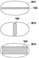
- the breast M11 of FIG. 11 when the mammary gland 100 is thin and widely distributed in the breast, the ratio of the area of the mammary gland becomes large in the method described in Japanese Patent Application Laid-Open No. 2012-135444.
- Tomosynthesis shooting is selected as the shooting mode.
- the breast M11 is a tomosynthesis capable of separating the overlap in the breast thickness direction as compared with the case where the mammary glands 100 are also distributed in the breast thickness direction as in the case of the breast M12 or the breast M13 shown in FIG.
- the advantage of shooting is small. Tomosynthesis imaging is performed multiple times with the breast compressed. Therefore, in the case of the breast M11 as shown in FIG. 11, the burden on the patient and the exposure dose are smaller when the simple imaging is performed.
- the present disclosure has been made in view of the above circumstances, and an object of the present disclosure is to enable the appropriate setting of the breast imaging mode.
- the imaging control device includes an image acquisition unit that acquires a first breast image by photographing the breast by the first imaging.
- a three-dimensional information derivation unit that derives three-dimensional information of the mammary gland included in the first breast image, It is equipped with a imaging mode setting unit that sets the imaging mode for the second imaging of the breast based on the three-dimensional information.
- the image acquisition unit acquires a second breast image by imaging a breast having the same positioning as the first imaging by the second imaging based on the set imaging mode.
- the three-dimensional information derivation unit derives any one of the volume of the mammary gland, the ratio of the volume of the mammary gland, and the thickness of the mammary gland in the region of interest of the breast as three-dimensional information. There may be.
- the region of interest may be the entire region of the breast.
- the region of interest may be a region in which the mammary gland exists in a predetermined ratio or more with respect to the thickness of the breast.
- the shooting mode setting unit sets any of simple two-dimensional shooting, tomosynthesis shooting, and combined shooting of simple shooting and tomosynthesis shooting as the shooting mode based on the three-dimensional information. It may be something to do.
- the imaging mode setting unit may further set the imaging mode based on the thickness of the breast.
- the imaging mode setting unit sets the imaging mode to simple two-dimensional imaging when the volume of the mammary gland or the ratio of the volume of the mammary gland is equal to or less than a predetermined threshold value. If the volume of the mammary gland or the ratio of the volume of the mammary gland is larger than the threshold value, the imaging mode may be set to tomosynthesis imaging.
- the threshold value may be set experimentally as appropriate according to the volume of the mammary gland or the ratio of the volume of the mammary gland.
- the volume of the mammary gland or the ratio of the volume of the mammary gland is equal to or less than a predetermined first threshold value, and the thickness of the breast is predetermined. If it is less than or equal to the second threshold, the imaging mode is set to simple two-dimensional imaging, the volume of the breast or the ratio of the volume of the breast is larger than the first threshold, and the thickness of the breast is the second. If it is less than or equal to the threshold value of, the imaging mode may be set to tomosynthesis imaging, and if the breast thickness is larger than the second threshold value, the imaging mode may be set to combined imaging.
- the first threshold value may be appropriately set experimentally according to the volume of the mammary gland or the ratio of the volume of the mammary gland.
- the second threshold value may be set experimentally as appropriate according to the thickness of the breast.
- the imaging mode setting unit sets the imaging mode to simple two-dimensional imaging, and the thickness of the mammary gland is determined. If it is larger than the value, the shooting mode may be set to tomosynthesis shooting.
- the threshold value may be set experimentally as appropriate according to the thickness of the mammary gland.
- the thickness of the breast gland is equal to or less than a predetermined third threshold value, and the thickness of the breast is predetermined. If it is less than or equal to the threshold value, set the imaging mode to simple two-dimensional imaging, and if the thickness of the breast gland is larger than the third threshold value and the thickness of the breast is less than or equal to the fourth threshold value, imaging is performed. If the mode is set to tomosynthesis imaging and the breast thickness is greater than the fourth threshold, the imaging mode may be set to combined imaging.
- the third threshold value may be set experimentally as appropriate according to the thickness of the mammary gland. Further, the fourth threshold value may be set experimentally as appropriate according to the thickness of the breast.
- the shooting control device may further include a notification unit for notifying at least one of the set shooting mode and the remaining time of the second shooting in the shooting mode.
- the imaging control method acquires a first breast image by photographing the breast by the first imaging, and obtains a first breast image. Derived the three-dimensional information of the mammary gland contained in the first breast image, Based on the 3D information, set the imaging mode for the second imaging of the breast, A second breast image is acquired by photographing a breast having the same positioning as the first imaging by the second imaging based on the set imaging mode.
- the other imaging control devices include a memory for storing an instruction to be executed by a computer and a memory.
- the processor comprises a processor configured to execute a stored instruction.
- the imaging mode of the breast can be appropriately set.
- FIG. 1 Schematic configuration diagram of a radiographic imaging system to which the imaging control device according to the embodiment of the present disclosure is applied.
- Diagram to illustrate tomosynthesis photography Diagram for explaining the setting of the region of interest in the first breast image The figure which shows the table which corresponded the relationship between 3D information and a shooting mode.
- FIG. 1 is a schematic configuration diagram of a radiation imaging system to which the imaging control device according to the embodiment of the present disclosure is applied
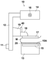
- FIG. 2 is a view of a mammography apparatus included in the radiation imaging system as viewed from the direction of arrow A in FIG.
- the radiographic imaging system 1 of the present embodiment includes a console 2 and a mammography apparatus 10.
- the console 2 includes a display unit 3, an input unit 4, and a shooting switch 5.
- the radiological imaging system 1 of the present embodiment is based on an instruction (imaging order) input from an external system (for example, RIS: Radiology Information System) via the console 2, and is operated by an operator such as a doctor or a radiologist.
- the mammography apparatus 10 has a function of performing tomosynthesis imaging of the breast and acquiring tomographic images at a plurality of tomographic planes of the breast.
- the mammography apparatus 10 can perform both tomosynthesis imaging and simple imaging to generate a tomographic image of the breast and a two-dimensional breast image.
- the two-dimensional breast image means a breast image acquired by simple imaging.
- the mammography apparatus 10 includes an arm portion 12 connected to a base (not shown) by a rotating shaft 11.
- An imaging table 13 is attached to one end of the arm portion 12, and an irradiation unit 14 is attached to the other end so as to face the photographing table 13.
- the arm portion 12 is configured so that only the end portion to which the radiation irradiation unit 14 is attached can be rotated, whereby the imaging table 13 can be fixed and only the radiation irradiation unit 14 can be rotated. It has become.
- the rotation of the arm portion 12 is controlled by the console 2.
- a radiation detector 15 such as a flat panel detector is provided inside the photographing table 13.
- the radiation detector 15 has a radiation detection surface 15A. Further, inside the photographing table 13, a charge amplifier that converts the charge signal read from the radiation detector 15 into a voltage signal, a correlated double sampling circuit that samples the voltage signal output from the charge amplifier, and a voltage signal.
- a circuit board or the like provided with an AD (Analog Digital) conversion unit or the like for converting the voltage into a digital signal is also installed.
- AD Analog Digital
- the radiation detector 15 is used in the present embodiment, it is not limited to the radiation detector 15 as long as it can detect the radiation and convert it into an image.
- the scattered radiation removal grid 20 is arranged so as to be able to be taken in and out between the surface of the photographing table 13 and the radiation detector 15.
- the radiation detector 15 can repeatedly record and read a radiation image, and may use a so-called direct type radiation detector that directly converts radiation such as X-rays into a charge, or radiation. You may use a so-called indirect radiation detector that once converts the visible light into visible light and then converts the visible light into a charge signal.
- the radiation image signal can be read out by turning on and off the TFT (Thin Film Transistor) switch, that is, the so-called TFT reading method, or by irradiating the read light. It is desirable to use a so-called optical reading method in which the light is read, but the present invention is not limited to this, and other materials may be used.
- the radiation source 16 is housed inside the radiation irradiation unit 14.
- the radiation source 16 emits X-rays as radiation, and the timing of irradiating the radiation from the radiation source 16 and the radiation generation conditions in the radiation source 16, that is, the selection of the material of the target and the filter, the tube voltage, the irradiation time, and the like are determined. It is controlled by the console 2.
- a compression plate 17 which is arranged above the imaging table 13 and presses and presses the breast M
- a support portion 18 which supports the compression plate 17, and a support portion 18 are vertically attached to FIGS. 1 and 2.
- a moving mechanism 19 for moving in a direction is provided.
- the distance between the compression plate 17 and the photographing table 13, that is, the compression thickness is input to the console 2.
- the moving mechanism 19 is provided with a display unit 40 such as a liquid crystal display for displaying various information directed to the patient.
- the display unit 40 displays a notification such as the remaining time until the end of shooting, which will be described later.
- the display unit 40 may have a built-in speaker that outputs sound.
- the display unit 3 is a display device such as a CRT (Cathode Ray Tube) or a liquid crystal display, and displays a first breast image and a second breast image acquired as described later, a message necessary for operation, and the like. To do.
- the display unit 3 may have a built-in speaker that outputs sound.
- the input unit 4 is composed of an input device such as a keyboard, a mouse, or a touch panel system, and receives input for operation of the mammography device 10 by an operator. It also accepts instructions for inputting various information such as shooting conditions and correcting the information necessary for shooting. In the present embodiment, each part of the mammography apparatus 10 operates according to the information input from the input unit 4 by the operator.
- the photographing switch 5 is provided from the viewpoint of safety, and a series of imaging including irradiation of radiation is executed only while the operator presses the imaging switch 5, and the operator performs the imaging switch 5. Shooting is stopped when you take your hand off.
- the shooting control program is installed on the console 2.
- the console 2 may be a workstation or a personal computer directly operated by the operator, or may be a server computer connected to them via a network.
- the shooting control program is recorded and distributed on a recording medium such as a DVD (Digital Versatile Disc) or a CD-ROM (Compact Disc Read Only Memory), and is installed in the computer from the recording medium.
- a recording medium such as a DVD (Digital Versatile Disc) or a CD-ROM (Compact Disc Read Only Memory)
- it is stored in the storage device of the server computer connected to the network or in the network storage in a state where it can be accessed from the outside, and is downloaded and installed in the computer upon request.
- FIG. 3 is a diagram showing a schematic configuration of a shooting control device realized by installing the shooting control program according to the present embodiment on the console 2.
- the photographing control device includes a CPU (Central Processing Unit) 21, a memory 22, and a storage 23 as a standard computer configuration.
- CPU Central Processing Unit
- the storage 23 is composed of a storage device such as a hard disk drive or an SSD (Solid State Drive), and stores various information including a shooting control program for driving each part of the mammography apparatus 10.
- the first breast image acquired by the first imaging and the second breast image acquired by the second imaging are also stored.
- the memory 22 temporarily stores a program or the like stored in the storage 23 in order for the CPU 21 to execute various processes.
- the imaging control program causes the mammography apparatus 10 to perform the first imaging and the second imaging described later, and acquires the first breast image and the second breast image.
- a three-dimensional information derivation process for deriving three-dimensional information of the mammary gland included in the first breast image acquired by the first imaging, and a imaging mode for the second imaging of the breast M based on the three-dimensional information.
- the imaging mode setting process for setting and the imaging mode for the second imaging are tomosynthesis imaging, by reconstructing the acquired plurality of projected images, a plurality of tomographic images at each of the plurality of tomographic planes of the breast M can be obtained.
- the display control process for displaying the second breast image acquired by imaging on the display unit 3 and the remaining time of the second imaging in the set imaging mode and imaging mode. Specify notification processing.
- the CPU 21 executes these processes according to the shooting control program, so that the computer constituting the console 2 has the image acquisition unit 31, the three-dimensional information derivation unit 32, the shooting mode setting unit 33, the reconstruction unit 34, and the display control. It functions as a unit 35 and a notification unit 36.
- the image acquisition unit 31 causes the mammography apparatus 10 to perform pre-shooting as the first shooting in order to optimize the shooting conditions for the second shooting and to set the shooting mode described later.
- the pre-imaging is an imaging in which a low dose of radiation is applied to the breast M according to the imaging conditions of the pre-imaging described later.
- the breast image acquired by the first imaging is defined as the first breast image.
- the first breast image may be displayed on the display unit 3 by the display control unit 35.
- the operator can determine whether or not the positioning of the breast M is appropriate based on the displayed first breast image. If the positioning is appropriate, a second shooting described later is performed. If the positioning is not appropriate, the imaging switch 5 described later is released, the breast M is repositioned, and the first imaging is performed again.
- the image acquisition unit 31 captures a second breast image having the same positioning as the first imaging by the second imaging based on the imaging mode set by the imaging mode setting unit 33 as described later.
- the second shooting include simple shooting, tomosynthesis shooting, and combined shooting of simple shooting and tomosynthesis shooting (hereinafter, simply referred to as combination shooting). These are set as shooting modes by the shooting mode setting unit 33. Taking a picture of a breast having the same positioning means that the first picture and the second picture are taken without releasing the state in which the breast M is pressed by the compression plate 17 and positioned.
- the image acquisition unit 31 moves the radiation source 16 by rotating the arm portion 12 of the mammography apparatus 10 around the rotation axis 11, and a plurality of radiation sources 16 due to the movement of the radiation source 16.
- the breast M is irradiated with radiation according to a predetermined first imaging condition for tomosynthesis imaging, and the radiation transmitted through the breast M is detected by the radiation detector 15, and a plurality of radiation sources are located at the plurality of radiation source positions.
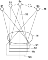
- FIG. 4 is a diagram for explaining the acquisition of the projected image Gi.
- the radiation source 16 is moved to each source position of S1, S2, ..., Sn, and the radiation source 16 is driven at each source position to irradiate the breast M with radiation, and the breast M is irradiated.
- the projected images G1, G2, ..., Gn are acquired corresponding to the respective radiation source positions S1 to Sn.
- the same dose of radiation is applied to the breast M.
- the acquired plurality of projected images Gi are stored in the storage 23.
- the image acquisition unit 31 uses a plurality of tomographic images generated from the plurality of projected images Gi by the reconstruction unit 34 described later as a second breast image. Get as.
- the radiation source position Sc shown in FIG. 4 is a radiation source position where the optical axis X0 of the radiation emitted from the radiation source 16 is orthogonal to the detection surface 15A of the radiation detector 15.
- the radiation source position Sc shall be referred to as a reference radiation source position Sc.
- the image acquisition unit 31 moves the radiation source 16 to the reference source position Sc by rotating the arm portion 12 of the mammography apparatus 10 around the rotation axis 11. Then, the image acquisition unit 31 irradiates the breast M with radiation under a predetermined second imaging condition for simple imaging, detects the radiation transmitted through the breast M with the radiation detector 15, and simplifies the breast M. A two-dimensional image is acquired as a second breast image.
- the image acquisition unit 31 rotates the arm portion 12 of the mammography apparatus 10 around the rotation axis 11 to cause the radiation source 16 as in the case of the simple imaging. Is moved to the reference source position Sc.
- the radiation source 16 may be moved to the radiation source position S1 to perform the first imaging.
- the radiation source 16 includes a filament that outputs an electron beam, a target that generates X-rays when the electron beams collide, and a filter that adjusts the energy spectrum of the X-rays.
- the target has a plurality of different anodic materials such as Mo (molybdenum), Rh (rhodium) and W (tungsten), which are optionally arranged.
- the filter has a number of different substances, such as Mo (molybdenum), Rh (rhodium), W (tungsten) and Al (aluminum), which are optionally arranged.
- the imaging conditions are conditions for adjusting the energy spectrum (radiation quality) of the radiation irradiating the breast M to obtain an appropriate radiation image, for example, the type of target constituting the radiation source 16, the type of filter, and Includes a grid condition that indicates the presence or absence of a scattered radiation removal grid. Further, the radiation generation condition consisting of the tube voltage applied between the filament and the target, and the mAs value (tube current ⁇ irradiation time) are also included in the imaging conditions.
- a table of shooting conditions for each of tomosynthesis shooting and simple shooting is stored in the storage 23.
- the type of target and filter, the tube voltage, the mAs value, and the presence or absence of the grid are set according to the thickness of the breast M.
- the target and filter are set as W / Al (target is W, filter is Al), and no grid is set as the first imaging condition.
- the tube voltage and mAs value are set according to the thickness of the breast M.
- the target and filter are set to W / Rh (target is W, filter is Rh), and the presence of a grid is set as the second shooting condition.
- the tube voltage and mAs value are set according to the thickness of the breast M. Therefore, when simple imaging is performed, as shown in FIG. 2, the scattered radiation removal grid 20 is inserted between the breast M and the radiation detector 15 in the imaging table 13.
- the pre-shooting that is, the shooting conditions at the time of the first shooting are also stored in the storage 23.
- the imaging conditions for the first imaging are the target and the filter, and for the grid, the second imaging condition for simple imaging. Although they are the same, the tube voltage and the mAs value are set to values smaller than those of the second imaging condition.
- the first imaging is performed when the position of the radiation source 16 is at the radiation source position S1
- the imaging conditions of the first imaging are the target and the filter, and the tomosynthesis for the grid. It is the same as the first imaging condition of imaging, but the tube voltage and mAs value are set to be smaller than those of the first imaging condition.
- the imaging conditions of the second imaging are optimized based on the first breast image acquired by the first imaging.
- the optimization method for example, the methods described in JP-A-2007-236804 or JP-A-2017-51752 can be used.
- the method described in JP-A-2007-236804 is based on the first breast image so that the density of the mammary gland region in the radiographic image or tomographic image obtained by the second imaging is appropriate.
- This is a method for optimizing the shooting conditions for shooting.
- the method described in JP-A-2017-51752 determines the presence or absence of an implant in the breast M based on the first breast image, and optimizes the imaging conditions for the second imaging according to the presence or absence of the implant. It is a method to do.
- the three-dimensional information derivation unit 32 acquires the three-dimensional information of the mammary gland included in the first breast image acquired by the first imaging. For this purpose, the three-dimensional information derivation unit 32 first derives the ratio of mammary glands for each pixel in the breast M included in the first breast image, that is, the mammary gland content rate.
- the method described in JP-A-2015-253245 can be used as a method for deriving the mammary gland content.
- the method described in JP-A-2015-253245 creates an adipose image having pixel values when all the mammary gland tissue of the breast is replaced with adipose tissue from the breast image, and the pixel value I (x, y) of the breast image.
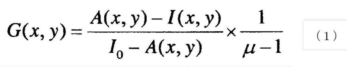
- the estimated pixel value A (x, y) of the fat image, the pixel value I0 in the blank region that directly reached the radiation detector 15 without passing through the breast M in the breast image, and the attenuation coefficient of radiation by fat is a method of deriving the mammary gland content G (x, y) for each pixel of the breast image by the following formula (1) based on the value ⁇ representing the ratio with the attenuation coefficient of radiation by the mammary gland.
- the mammary gland content G (x, y) of each pixel in the entire region of the breast M included in the first breast image is derived.
- the three-dimensional information derivation unit 32 multiplies the mammary gland content G (x, y) by the thickness of the breast M, so that the mammary glands of each pixel in the entire region of the breast M included in the first breast image MG1.
- the thickness T (x, y) of is derived.
- the compression thickness of the breast M by the compression plate 17 is used for the thickness of the breast M.
- the thickness of the breast M near the skin line that is not in contact with the compression plate 17 may be derived from the compression thickness by regarding the contour in the cross section of the breast M in the thickness direction as an arc.
- the three-dimensional information derivation unit 32 includes the derived mammary gland thickness T (x, y) in the breast M by multiplying the area of the entire region of the breast M included in the first breast image MG1.
- the volume V0 of the mammary gland is derived as three-dimensional information of the mammary gland.
- the mammary gland volume V0 contained in the breast M may be divided by the breast M volume to derive the ratio R0 of the mammary gland volume as three-dimensional information.
- the volume of the breast M can be derived by multiplying the area of the entire region of the breast M included in the first breast image MG1 by the thickness of the breast M.
- the representative value T0 (hereinafter referred to as the thickness representative value) of the mammary gland thickness T (x, y) may be used as the three-dimensional information.
- the representative thickness value T0 any one of the maximum value, the average value, the median value, and the like of the thickness T (x, y) of the mammary gland can be used.
- the typical thickness value T0 corresponds to the thickness of the mammary gland according to the present disclosure.
- the three-dimensional information of the mammary gland for the entire region of the breast M in the first breast image is derived, but the present invention is not limited to this.
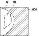
- the region where the mammary gland content G (x, y) is equal to or higher than a predetermined value (for example, 10%) is set as the region of interest 50, and the region of interest 50 is set.
- a predetermined value for example, 10%
- the thickness T (x, y) of the mammary gland within, the volume V1 of the mammary gland, the ratio R1 of the volume of the mammary gland, or the representative thickness T1 in the region of interest 50 may be derived as three-dimensional information. ..
- the volume V1 of the mammary gland in the region of interest 50 can be derived by multiplying the area of the region of interest 50 by the thickness T (x, y) of the mammary gland in the region of interest 50.
- the ratio R1 of the mammary gland volume in the region of interest 50 can be derived by dividing the volume V1 of the mammary gland in the region of interest 50 by the volume of the breast M in the region of interest 50.
- the volume of the breast M in the region of interest 50 can be derived by multiplying the area of the breast M in the region of interest 50 in the first breast image MG1 by the thickness of the breast M.
- the mammary gland volume ratio R0 can also be derived using the following formula (2) described in JP-A-2015-253245.
- the method for deriving the three-dimensional information of the mammary gland is not limited to the method described in Japanese Patent Application Laid-Open No. 2015-253245, and any method can be used.
- the method described in "Robust Breast composition Measurement-Volpara", Ralph Highnam et al., IWDM2010, LNCS; 6136: 342-349, 2010. may be used.
- the thickness of the mammary gland is T (x, y)
- the pixel value of each pixel in the breast image is I (x, y)
- Is F the radiation attenuation coefficient of fat is ⁇ f
- the radiation attenuation coefficient of mammary gland is ⁇ d
- the thickness of the mammary gland is derived by the following equation (3).
- the mammary gland thickness T (x, y) was derived in the entire region of the breast M included in the first breast image MG1 by the method described in the above-mentioned document of Highnam et al., And the derived mammary gland thickness T was derived.
- the volume V0 of the mammary gland contained in the breast M can be derived as three-dimensional information of the mammary gland.
- the ratio R0 of the volume of the mammary gland obtained by dividing the volume V0 of the mammary gland contained in the breast M by the volume of the breast M can be derived as three-dimensional information.
- a region in which the thickness of the mammary gland is equal to or larger than a predetermined value may be set as the region of interest, and three-dimensional information may be derived only within the region of interest. ..
- the imaging mode setting unit 33 sets the imaging mode for the second imaging of the breast M based on the three-dimensional information.
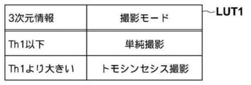
- a table in which the relationship between the three-dimensional information and the shooting mode is associated is stored in the storage 23.
- FIG. 6 is a diagram showing a table in which the relationship between the three-dimensional information and the shooting mode is associated.
- simple shooting is associated with the three-dimensional information below the first threshold value Th1
- the three-dimensional information larger than the first threshold value Th1 is associated with simple shooting.
- Tomosynthesis imaging is associated.
- the volumes V0 and V1 of the mammary gland, the volume ratios R0 and R1 of the mammary gland, and the representative thickness values T0 and T1 are collectively shown as three-dimensional information, but in reality, the three-dimensional information is derived.
- a table is prepared according to the type of three-dimensional information derived by the unit 32. Further, in the table, the first threshold value Th1 is set according to the type of three-dimensional information to be derived. That is, different first threshold values Th1 are set according to the mammary gland volumes V0 and V1, the mammary gland volume ratios R0 and R1, and the thickness representative values T0 and T1.
- the imaging mode setting unit 33 may set the imaging mode using the thickness of the breast M in addition to the three-dimensional information.
- the storage 23 may store a table in which the relationship between the three-dimensional information and the imaging mode according to the thickness of the breast M is associated.
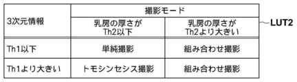
- FIG. 7 is a diagram showing a table in which the relationship between the three-dimensional information and the imaging mode according to the thickness of the breast is associated. Since tomosynthesis imaging is performed by irradiating the breast M with radiation from each of a plurality of radiation source positions, the angle of incidence of the radiation on the radiation detector 15 is different at each imaging position. Therefore, when imaging is performed using the grid, depending on the position of the radiation source, radiation may be blocked by the grid, and the amount of radiation reaching the radiation detector 15 may be reduced. Therefore, the grid is not used when performing tomosynthesis imaging.
- the noise of the projected image and the tomographic image will increase due to the influence of scattered rays, and the image quality will deteriorate.
- the degree of radiation scattering increases, and noise caused by scattered rays increases.
- the table LUT2 is associated with simple imaging when the thickness of the breast M is the threshold Th2 or less with respect to the three-dimensional information of the first threshold Th1 or less.
- the threshold value Th2 When the threshold value Th2 is exceeded, combined imaging of simple imaging and tomosynthesis imaging is associated.
- tomosynthesis imaging is associated with the three-dimensional information exceeding the first threshold value Th1 when the thickness of the breast is the threshold value Th2 or less, and simple imaging and simple imaging are performed when the threshold value exceeds Th2.
- Combination photography of tomosynthesis photography is associated.
- the first threshold value Th1 for three-dimensional information is used in both FIGS. 6 and 7, different threshold values may be set in each of FIGS. 6 and 7.
- the second threshold value may be set to a different value depending on the type of three-dimensional information.
- the imaging mode setting unit 33 sets the imaging mode for the second imaging with reference to the table LUT1 or the table LUT2 based on the three-dimensional information derived by the three-dimensional information derivation unit 32 and the thickness of the breast M. To do. That is, when only the three-dimensional information is used, the shooting mode setting unit 33 refers to the table LUT1 shown in FIG. 6, and when the three-dimensional information is equal to or less than the first threshold value Th1, the shooting mode is set to simple shooting. If the 3D information is larger than the first threshold value Th1, the shooting mode is set to tomosynthesis shooting.
- the imaging mode setting unit 33 refers to the table LUT2 shown in FIG. 7, and when the three-dimensional information is equal to or less than the first threshold value Th1, the breast M When the thickness of is less than the threshold Th2, the imaging mode is set to simple imaging, and when the thickness of the breast M is larger than the threshold Th2, the imaging mode is set to combined imaging.
- the imaging mode is set to tomosynthesis imaging, and the thickness of the breast M is set.
- the shooting mode is set to combined shooting.
- the set shooting mode is output to the image acquisition unit 31.
- the image acquisition unit 31 takes a second image of the breast M in the set imaging mode and acquires the second breast image.
- the second breast image is a simple two-dimensional image.
- the imaging mode is tomosynthesis imaging
- the second breast image is a tomographic image reconstructed using the projected image Gi acquired by tomosynthesis imaging. The reconstruction will be described later.
- the imaging mode is combination imaging
- the second breast image is a simple two-dimensional image and a tomographic image.
- the display control unit 35 displays the first breast image acquired by the first imaging and the second breast image acquired by the second imaging according to the imaging mode on the display unit 3.
- the display control unit 35 displays the simple two-dimensional image on the display unit 3 when the imaging mode is simple imaging.
- the display control unit 35 displays the tomographic image on the display unit 3 when the photographing mode is tomosynthesis imaging.
- the display control unit 35 displays a simple two-dimensional image and a tomographic image on the display unit 3 when the shooting modes are combined shooting.
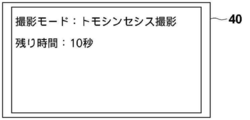
- the notification unit 36 sets at least one of the shooting mode and the remaining time of the second shooting to the display unit 40 and the display unit 3 provided in the mammography apparatus 10. Notify by displaying. In the present embodiment, both the shooting mode and the remaining time of the second shooting are notified.
- FIG. 9 is a diagram showing a notification displayed on the display unit 40. As shown in FIG. 9, the display unit 40 displays “tomosynthesis shooting” as the shooting mode and “10 seconds” as the remaining time. The remaining time is counted down as the shooting progresses, and when the second shooting is completed, the remaining time becomes 0. Further, the same notification is given to the display unit 3. In addition, a bar indicating the remaining time may be displayed instead of a numerical value as the remaining time.
- the shooting mode is simple shooting, at least one of the shooting mode and the remaining time of the second shooting may be notified.
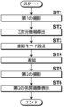
- FIG. 10 is a flowchart showing the processing performed in the present embodiment. It is assumed that the positioning of the breast M on the imaging table 13 has been completed. The process is started when the operator gives an instruction for pre-imaging from the input unit 4, and the image acquisition unit 31 causes the mammography apparatus 10 to perform the first imaging to acquire the first breast image MG1 (step ST1). ). At this time, the shooting switch 5 is pressed by the operator, and the state is maintained until the second shooting is completed unless the positioning is redone.
- the three-dimensional information derivation unit 32 derives the three-dimensional information of the mammary gland included in the first breast image MG1 (step ST2). Then, the imaging mode setting unit 33 sets the imaging mode for the second imaging of the breast M based on the three-dimensional information (step ST3). In addition, the notification unit 36 notifies the set shooting mode and the remaining time of the second shooting (step ST4). Further, the image acquisition unit 31 performs a second image based on the set image capture mode and acquires a second breast image (step ST5). Then, the display control unit 35 displays the second breast image on the display unit 3 (step ST6), and ends the process. The operator can release the shooting switch 5 after confirming that the shooting has been completed by viewing the notification by the notification unit 36.
- the second imaging is performed without moving the radiation source 16. You just have to do.
- the position of the radiation source 16 at the time of the first imaging is the reference radiation source position Sc, and the imaging mode is set to tomosynthesis imaging, the radiation source 16 is moved to the radiation source position S1 and then the second image is taken. You just have to take a picture of. In this case, while the radiation source 16 is moving, the filter and the target may be changed according to the first imaging condition, and the grid 20 may be retracted.
- the imaging mode is set to combination imaging
- simple imaging is performed first, and the radiation source 16 is set to the radiation source position S1.
- the second shooting may be performed.
- the position of the radiation source 16 at the time of the first imaging is the radiation source position S1 and the imaging mode is set to simple imaging
- the second shooting may be performed.
- the filter and the target may be changed and the grid 20 may be inserted according to the second imaging condition. If the position of the radiation source 16 at the time of the first imaging is the radiation source position S1 and the imaging mode is set to tomosynthesis imaging, the second imaging can be performed without moving the radiation source 16. Good.
- the position of the radiation source 16 at the time of the first imaging is the radiation source position S1 and the imaging mode is set to combination imaging, tomosynthesis imaging is performed first, and after the completion of tomosynthesis imaging, the radiation source 16 The second image may be taken after moving to the reference radiation source position Sc.
- the imaging mode for the second imaging of the breast M is set based on the three-dimensional information of the mammary gland included in the first breast image acquired by the first imaging.
- the second breast image is acquired by photographing the breast in the same positioning as the first image by the second image based on the set imaging mode.
- the three-dimensional information of the mammary gland includes not only information on the direction of expansion in the breast image but also information on the direction of thickness of the breast at the time of imaging. Therefore, the three-dimensional information of the mammary gland more appropriately represents the distribution of the mammary gland contained in the breast M. Therefore, according to the present embodiment, the imaging mode of the breast M can be appropriately set.
- the imaging mode can be set more appropriately.
- the burden on the patient is large. For this reason, if it is not known what kind of imaging is currently being performed, the patient will be anxious because it is not possible to know how long the state of pressing the breast M will continue. Further, if the operator releases the shooting switch 5 before the shooting is finished, the shooting is interrupted, so that the operator cannot release the shooting switch 5 during the shooting. However, if the timing at which the shooting ends is not known, it is not possible to know how long the shooting switch 5 should be held down.
- the set shooting mode and the remaining time of the second shooting are notified. Therefore, the patient can know the current imaging mode and the time until the imaging is completed, which can reduce the patient's anxiety. In addition, since the photographer can know the timing when the shooting is finished by the notification, he / she can take his / her hand off the shooting switch 5 with confidence.
- the radiation is not particularly limited, and ⁇ rays, ⁇ rays, etc. can be applied in addition to X-rays.
- the notification unit 36 displays the notification on the display unit 3 and the display unit 40, but the present invention is not limited to this.
- the notification unit 36 may display the notification on the display unit 3 or the display unit 40.
- the display may be changed to or in addition to the display, and a voice notification may be performed.
- a processing unit that executes various processes such as an image acquisition unit 31, a three-dimensional information derivation unit 32, a shooting mode setting unit 33, a reconstruction unit 34, a display control unit 35, and a notification unit 36
- various processors processors shown below can be used.
- the various processors include a CPU, which is a general-purpose processor that executes software (program) and functions as various processing units, and a circuit after manufacturing an FPGA (Field Programmable Gate Array) or the like.
- Dedicated electricity which is a processor with a circuit configuration specially designed to execute specific processing such as programmable logic device (PLD), ASIC (Application Specific Integrated Circuit), which is a processor whose configuration can be changed. Circuits and the like are included.
- One processing unit may be composed of one of these various processors, or a combination of two or more processors of the same type or different types (for example, a combination of a plurality of FPGAs or a combination of a CPU and an FPGA). ) May be configured. Further, a plurality of processing units may be configured by one processor.
- one processor is configured by a combination of one or more CPUs and software, as represented by a computer such as a client and a server. There is a form in which this processor functions as a plurality of processing units.
- SoC System On Chip
- the various processing units are configured by using one or more of the various processors as a hardware structure.
- circuitry in which circuit elements such as semiconductor elements are combined can be used.
Landscapes
- Health & Medical Sciences (AREA)
- Engineering & Computer Science (AREA)
- Life Sciences & Earth Sciences (AREA)
- Medical Informatics (AREA)
- Physics & Mathematics (AREA)
- Radiology & Medical Imaging (AREA)
- General Health & Medical Sciences (AREA)
- Nuclear Medicine, Radiotherapy & Molecular Imaging (AREA)
- Surgery (AREA)
- Public Health (AREA)
- Optics & Photonics (AREA)
- Biomedical Technology (AREA)
- Heart & Thoracic Surgery (AREA)
- Molecular Biology (AREA)
- High Energy & Nuclear Physics (AREA)
- Animal Behavior & Ethology (AREA)
- Biophysics (AREA)
- Pathology (AREA)
- Veterinary Medicine (AREA)
- Human Computer Interaction (AREA)
- General Physics & Mathematics (AREA)
- Theoretical Computer Science (AREA)
- Dentistry (AREA)
- Oral & Maxillofacial Surgery (AREA)
- Quality & Reliability (AREA)
- Computer Vision & Pattern Recognition (AREA)
- Multimedia (AREA)
- Apparatus For Radiation Diagnosis (AREA)
Abstract
画像取得部が、第1の撮影によって乳房を撮影することにより、第1の乳房画像を取得する。3次元情報導出部が、第1の乳房画像に含まれる乳腺の3次元情報を導出する。撮影モード設定部が、3次元情報に基づいて、乳房の第2の撮影のための撮影モードを設定する。画像取得部は、設定された撮影モードに基づく第2の撮影によって、第1の撮影と同一ポジショニングの乳房を撮影することにより、第2の乳房画像を取得する。
Description
本開示は、撮影制御装置、方法およびプログラムに関する。
近年、乳がんの早期発見を促すため、乳房を撮影する放射線画像撮影装置(マンモグラフィと呼ばれる)を用いた画像診断が注目されている。マンモグラフィにおいては、乳房は撮影台の上に置かれ、圧迫板により圧迫された状態で撮影が行われる。乳房は主に乳腺組織と脂肪組織とからなり、乳腺組織に隠れた腫瘤および石灰化等の病変を発見することが診断の上で重要となっている。このため、マンモグラフィで撮影された乳房の放射線画像(乳房画像)は、専用の操作端末等で画像処理された後、医師による診断に供される。医師は、乳房画像をディスプレイ等に表示して読影することにより、異常部位の有無を調べる。
ここで、乳房は乳腺組織および脂肪組織が混在している。乳腺密度が高い乳房の場合、乳房画像において異常部位が乳腺により隠れてしまい、その結果、異常部位が見え難くなる場合がある。
一方、マンモグラフィにおいて、放射線源を移動させて複数の線源位置から乳房に放射線を照射して撮影を行い、これにより取得した複数の投影画像を加算して所望の断層面を強調した断層画像を生成するトモシンセシス撮影が提案されている。トモシンセシス撮影では、撮影装置の特性および必要な断層画像に応じて、放射線源を放射線検出器と平行に移動させたり、円または楕円の弧を描くように移動させたりして、複数の線源位置において乳房を撮影することにより複数の投影画像を取得し、単純逆投影法またはフィルタ逆投影法等の逆投影法等を用いてこれらの投影画像を再構成して断層画像を生成する。
このような断層画像を乳房における複数の断層面において生成することにより、乳房内において断層面が並ぶ深さ方向に重なり合った構造を分離することができる。このため、従来の単純撮影により取得される2次元画像(以下、単純2次元画像とする)においては検出が困難であった病変を発見することが可能となる。
ところで、放射線により被写体の撮影を行う際には、被写体内において発生した散乱線の影響によるコントラストの低下を防止するために、散乱線除去グリッド(以下単にグリッドとする)が使用される。一方、トモシンセシス撮影は複数の線源位置のそれぞれから放射線を被写体に照射して撮影を行うため、放射線検出器に対する放射線の入射角が各撮影位置において異なる。このため、グリッドを用いて撮影を行うと、線源位置によっては、放射線がグリッドにより遮断されるケラレが生じてしまい、放射線検出器に到達する放射線量が少なくなってしまう。したがって、トモシンセシス撮影を行う場合には、グリッドが使用されないこととなる。
しかしながら、グリッドを使用しないと、散乱線の影響により投影画像、さらには断層画像のノイズが増加して、画質が劣化する。とくに、乳房が厚い患者の場合、放射線の散乱の程度が大きくなり、散乱線に起因するノイズが多くなる。その結果、トモシンセシス撮影を行ったにも拘わらず、単純2次元画像よりも異常部位を検出しにくくなる場合がある。
このため、マンモグラフィにおいて、トモシンセシス撮影および単純撮影の双方を行う手法が提案されている(特開2007-50264号公報参照)。しかしながら、トモシンセシス撮影および単純撮影の双方を行うと、被写体への被曝線量が増大してしまう。この問題を解決するために、過去に取得された乳房画像を用いて、乳房の乳腺密度を算出し、乳腺密度に応じて、単純撮影およびトモシンセシス撮影のいずれかに撮影モードを切り替える手法が提案されている(特開2012-135444号公報参照)。具体的には、特開2012-135444号公報に記載された手法においては、乳腺密度が大きいほどトモシンセシス撮影が行われるように撮影モードが切り替えられる。なお、特開2012-135444号公報においては、乳房画像に含まれる全領域または予め定められた領域内における、比較的低濃度の画素を乳腺の画素と見なし、乳房画像に含まれる全領域または予め定められた領域における乳腺領域の面積の割合を乳腺量として算出している。
しかしながら、特開2012-135444号公報に記載されているように、乳腺領域の面積の割合に基づく手法では、適切な撮影モードを選択できない場合がある。例えば、図11の乳房M11に示すように、乳房内に乳腺100が薄くかつ広く分布している場合、特開2012-135444号公報に記載された手法では乳腺の面積の割合が大きくなるため、撮影モードとしてトモシンセシス撮影が選択される。しかしながら、乳房M11は、図11に示す乳房M12または乳房M13のように、乳房の厚さ方向にも乳腺100が分布している場合と比較して、乳房の厚さ方向の重なりを分離できるトモシンセシス撮影の利点が小さい。トモシンセシス撮影は、乳房を圧迫した状態で複数回の撮影が行われる。このため、図11に示すような乳房M11の場合、単純撮影を行った方が、患者への負担および被曝量が小さい。
本開示は上記事情に鑑みなされたものであり、乳房の撮影モードを適切に設定できるようにすることを目的とする。
本開示による撮影制御装置は、第1の撮影によって乳房を撮影することにより、第1の乳房画像を取得する画像取得部と、
第1の乳房画像に含まれる乳腺の3次元情報を導出する3次元情報導出部と、
3次元情報に基づいて、乳房の第2の撮影のための撮影モードを設定する撮影モード設定部とを備え、
画像取得部は、設定された撮影モードに基づく第2の撮影によって、第1の撮影と同一ポジショニングの乳房を撮影することにより、第2の乳房画像を取得する。
第1の乳房画像に含まれる乳腺の3次元情報を導出する3次元情報導出部と、
3次元情報に基づいて、乳房の第2の撮影のための撮影モードを設定する撮影モード設定部とを備え、
画像取得部は、設定された撮影モードに基づく第2の撮影によって、第1の撮影と同一ポジショニングの乳房を撮影することにより、第2の乳房画像を取得する。
なお、本開示による撮影制御装置においては、3次元情報導出部は、乳房の関心領域における乳腺の体積、乳腺の体積の割合、および乳腺の厚さのいずれかを3次元情報として導出するものであってもよい。
また、本開示による撮影制御装置においては、関心領域は、乳房の全体領域であってもよい。
また、本開示による撮影制御装置においては、関心領域は、乳房の厚さに対して乳腺が予め定められた割合以上存在する領域であってもよい。
また、本開示による撮影制御装置においては、撮影モード設定部は、3次元情報に基づいて、単純2次元撮影、トモシンセシス撮影、および単純撮影とトモシンセシス撮影との組み合わせ撮影のいずれかを撮影モードとして設定するものであってもよい。
また、本開示による撮影制御装置においては、撮影モード設定部は、さらに乳房の厚さにも基づいて撮影モードを設定するものであってもよい。
また、本開示による撮影制御装置においては、撮影モード設定部は、乳腺の体積または乳腺の体積の割合が予め定められたしきい値以下の場合は、撮影モードを単純2次元撮影に設定し、乳腺の体積または乳腺の体積の割合がしきい値より大きい場合は、撮影モードをトモシンセシス撮影に設定するものであってもよい。
この場合、しきい値は、乳腺の体積または乳腺の体積の割合に応じて適宜実験的に設定すればよい。
また、本開示による撮影制御装置においては、撮影モード設定部は、乳腺の体積または乳腺の体積の割合が予め定められた第1のしきい値以下であり、かつ乳房の厚さが予め定められた第2のしきい値以下の場合は、撮影モードを単純2次元撮影に設定し、乳腺の体積または乳腺の体積の割合が第1のしきい値より大きく、かつ乳房の厚さが第2のしきい値以下の場合は、撮影モードをトモシンセシス撮影に設定し、乳房の厚さが第2のしきい値より大きい場合は、撮影モードを組み合わせ撮影に設定するものであってもよい。
この場合、第1のしきい値は、乳腺の体積または乳腺の体積の割合に応じて適宜実験的に設定すればよい。また、第2のしきい値は、乳房の厚さに応じて適宜実験的に設定すればよい。
また、本開示による撮影制御装置においては、撮影モード設定部は、乳腺の厚さが予め定められたしきい値以下の場合は、撮影モードを単純2次元撮影に設定し、乳腺の厚さがしきい値より大きい場合は、撮影モードをトモシンセシス撮影に設定するものであってもよい。
この場合、しきい値は、乳腺の厚さに応じて適宜実験的に設定すればよい。
また、本開示による撮影制御装置においては、撮影モード設定部は、乳腺の厚さが予め定められた第3のしきい値以下であり、かつ乳房の厚さが予め定められた第4のしきい値以下の場合は、撮影モードを単純2次元撮影に設定し、乳腺の厚さが第3のしきい値より大きく、かつ乳房の厚さが第4のしきい値以下の場合は、撮影モードをトモシンセシス撮影に設定し、乳房の厚さが第4のしきい値より大きい場合は、撮影モードを組み合わせ撮影に設定するものであってもよい。
この場合、第3のしきい値は、乳腺の厚さに応じて適宜実験的に設定すればよい。また、第4のしきい値は、乳房の厚さに応じて適宜実験的に設定すればよい。
また、本開示による撮影制御装置においては、設定された撮影モードおよび撮影モードによる第2の撮影の残り時間の少なくとも一方を通知する通知部をさらに備えるものであってもよい。
本開示による撮影制御方法は、第1の撮影によって乳房を撮影することにより、第1の乳房画像を取得し、
第1の乳房画像に含まれる乳腺の3次元情報を導出し、
3次元情報に基づいて、乳房の第2の撮影のための撮影モードを設定し、
設定された撮影モードに基づく第2の撮影によって、第1の撮影と同一ポジショニングの乳房を撮影することにより、第2の乳房画像を取得する。
第1の乳房画像に含まれる乳腺の3次元情報を導出し、
3次元情報に基づいて、乳房の第2の撮影のための撮影モードを設定し、
設定された撮影モードに基づく第2の撮影によって、第1の撮影と同一ポジショニングの乳房を撮影することにより、第2の乳房画像を取得する。
なお、本開示による撮影制御方法をコンピュータに実行させるためのプログラムとして提供してもよい。
本開示による他の撮影制御装置は、コンピュータに実行させるための命令を記憶するメモリと、
記憶された命令を実行するよう構成されたプロセッサとを備え、プロセッサは、
第1の撮影によって乳房を撮影することにより、第1の乳房画像を取得し、
第1の乳房画像に含まれる乳腺の3次元情報を導出し、
3次元情報に基づいて、乳房の第2の撮影のための撮影モードを設定し、
設定された撮影モードに基づく第2の撮影によって、第1の撮影と同一ポジショニングの乳房を撮影することにより、第2の乳房画像を取得する処理を実行する。
記憶された命令を実行するよう構成されたプロセッサとを備え、プロセッサは、
第1の撮影によって乳房を撮影することにより、第1の乳房画像を取得し、
第1の乳房画像に含まれる乳腺の3次元情報を導出し、
3次元情報に基づいて、乳房の第2の撮影のための撮影モードを設定し、
設定された撮影モードに基づく第2の撮影によって、第1の撮影と同一ポジショニングの乳房を撮影することにより、第2の乳房画像を取得する処理を実行する。
本開示によれば、乳房の撮影モードを適切に設定することができる。
以下、図面を参照して本開示の実施形態について説明する。図1は本開示の実施形態による撮影制御装置を適用した放射線画像撮影システムの概略構成図、図2は放射線画像撮影システムに含まれるマンモグラフィ装置を図1の矢印A方向から見た図である。
図1に示すように、本実施形態の放射線画像撮影システム1は、コンソール2およびマンモグラフィ装置10を備える。コンソール2は、表示部3、入力部4および撮影スイッチ5を備える。
本実施形態の放射線画像撮影システム1は、コンソール2を介して外部のシステム(例えば、RIS:Radiology Information System)から入力された指示(撮影オーダ)に基づいて、医師および放射線技師等の操作者の操作により、マンモグラフィ装置10により、乳房のトモシンセシス撮影を行って、乳房の複数の断層面における断層画像を取得する機能を有する。本実施形態においては、マンモグラフィ装置10はトモシンセシス撮影および単純撮影の双方を行って、乳房の断層画像および2次元の乳房画像を生成することが可能なものである。なお、2次元の乳房画像は単純撮影により取得される乳房画像を意味する。
マンモグラフィ装置10は、不図示の基台に対して回転軸11により連結されたアーム部12を備えている。アーム部12の一方の端部には撮影台13が、その他方の端部には撮影台13と対向するように放射線照射部14が取り付けられている。アーム部12は、放射線照射部14が取り付けられた端部のみを回転することが可能に構成されており、これにより、撮影台13を固定して放射線照射部14のみを回転することが可能となっている。なお、アーム部12の回転は、コンソール2により制御される。
撮影台13の内部には、フラットパネルディテクタ等の放射線検出器15が備えられている。放射線検出器15は放射線の検出面15Aを有する。また、撮影台13の内部には、放射線検出器15から読み出された電荷信号を電圧信号に変換するチャージアンプ、チャージアンプから出力された電圧信号をサンプリングする相関2重サンプリング回路、および電圧信号をデジタル信号に変換するAD(Analog Digital)変換部等が設けられた回路基板等も設置されている。また、本実施形態においては、放射線検出器15を用いているが、放射線を検出して画像に変換することができれば、放射線検出器15に限定されるものではない。
なお、撮影台13内においては、撮影台13の表面と放射線検出器15との間に、散乱線除去グリッド20が出し入れ可能に配置される。
放射線検出器15は、放射線画像の記録および読み出しを繰り返して行うことができるものであり、X線等の放射線を直接電荷に変換する、いわゆる直接型の放射線検出器を用いてもよいし、放射線を一旦可視光に変換し、その可視光を電荷信号に変換する、いわゆる間接型の放射線検出器を用いるようにしてもよい。また、放射線画像信号の読出方式としては、TFT(Thin Film Transistor)スイッチをオンおよびオフすることによって放射線画像信号が読み出される、いわゆるTFT読出方式のもの、または読取光を照射することによって放射線画像信号が読み出される、いわゆる光読出方式のものを用いることが望ましいが、これに限らずその他のものを用いるようにしてもよい。
放射線照射部14の内部には、放射線源16が収納されている。放射線源16は放射線としてX線を出射するものであり、放射線源16から放射線を照射するタイミングおよび放射線源16における放射線発生条件、すなわちターゲットおよびフィルタの材質の選択、管電圧並びに照射時間等は、コンソール2により制御される。
また、アーム部12には、撮影台13の上方に配置されて乳房Mを押さえつけて圧迫する圧迫板17、圧迫板17を支持する支持部18、および支持部18を図1および図2の上下方向に移動させる移動機構19が設けられている。なお、圧迫板17と撮影台13との間隔、すなわち圧迫厚はコンソール2に入力される。また、移動機構19には、患者に向けた各種情報を表示するための液晶ディスプレイ等の表示部40が設けられている。表示部40には、後述する撮影終了までの残り時間等の通知が表示される。表示部40は音声を出力するスピーカを内蔵するものであってもよい。
表示部3は、CRT(Cathode Ray Tube)または液晶ディスプレイ等の表示装置であり、後述するように取得された第1の乳房画像および第2の乳房画像の他、操作に必要なメッセージ等を表示する。なお、表示部3は音声を出力するスピーカを内蔵するものであってもよい。
入力部4はキーボード、マウスまたはタッチパネル方式等の入力装置からなり、操作者によるマンモグラフィ装置10の操作のための入力を受け付ける。また、撮影を行うために必要な、撮影条件等の各種情報の入力および情報の修正の指示も受け付ける。本実施形態においては、操作者が入力部4から入力した情報に従って、マンモグラフィ装置10の各部が動作する。
撮影スイッチ5は、安全性の観点から設けられているものであり、操作者が撮影スイッチ5を押下している間においてのみ放射線の照射を含む一連の撮影が実行され、操作者が撮影スイッチ5を手から離したときには撮影が中止される。
コンソール2には、本実施形態による撮影制御プログラムがインストールされている。本実施形態においては、コンソール2は、操作者が直接操作するワークステーションあるいはパーソナルコンピュータでもよいし、それらとネットワークを介して接続されたサーバコンピュータでもよい。撮影制御プログラムは、DVD(Digital Versatile Disc)、CD-ROM(Compact Disc Read Only Memory)等の記録媒体に記録されて配布され、その記録媒体からコンピュータにインストールされる。もしくは、ネットワークに接続されたサーバコンピュータの記憶装置、あるいはネットワークストレージに、外部からアクセス可能な状態で記憶され、要求に応じてコンピュータにダウンロードされ、インストールされる。
図3はコンソール2に本実施形態による撮影制御プログラムをインストールすることにより実現される撮影制御装置の概略構成を示す図である。図3に示すように、撮影制御装置は、標準的なコンピュータの構成として、CPU(Central Processing Unit)21、メモリ22およびストレージ23を備えている。
ストレージ23は、ハードディスクドライブまたはSSD(Solid State Drive)等のストレージデバイスからなり、マンモグラフィ装置10の各部を駆動するための撮影制御プログラムを含む各種情報が記憶されている。第1の撮影により取得された第1の乳房画像および第2の撮影により取得された第2の乳房画像も記憶される。
メモリ22には、各種処理をCPU21に実行させるために、ストレージ23に記憶されたプログラム等が一時的に記憶される。撮影制御プログラムは、CPU21に実行させる処理として、後述する第1の撮影および第2の撮影をマンモグラフィ装置10に行わせて、第1の乳房画像および第2の乳房画像を取得する画像取得処理、第1の撮影により取得される第1の乳房画像に含まれる乳腺の3次元情報を導出する3次元情報導出処理、3次元情報に基づいて、乳房Mの第2の撮影のための撮影モードを設定する撮影モード設定処理、第2の撮影の撮影モードがトモシンセシス撮影の場合に、取得された複数の投影画像を再構成することにより、乳房Mの複数の断層面のそれぞれにおける複数の断層画像を生成する再構成処理、撮影により取得された第2の乳房画像を表示部3に表示する表示制御処理、並びに設定された撮影モードおよび撮影モードによる第2の撮影の残り時間の少なくとも一方を通知する通知処理を規定する。
そして、CPU21が撮影制御プログラムに従いこれらの処理を実行することで、コンソール2を構成するコンピュータは、画像取得部31、3次元情報導出部32、撮影モード設定部33、再構成部34、表示制御部35および通知部36として機能する。
画像取得部31は、第2の撮影の撮影条件を最適化するため、および後述する撮影モードを設定するために、マンモグラフィ装置10にプレ撮影を第1の撮影として行わせる。プレ撮影は、後述するプレ撮影の撮影条件に従って、乳房Mに低線量の放射線を照射する撮影である。第1の撮影により取得される乳房画像を第1の乳房画像とする。
なお、第1の乳房画像を、表示制御部35により表示部3に表示してもよい。この場合、操作者は表示された第1の乳房画像により、乳房Mのポジショニングが適切か否かを判断することができる。ポジショニングが適切であれば、後述する第2の撮影を行う。ポジショニングが適切でない場合、後述する撮影スイッチ5から手を離して、乳房Mのポジショニングをやり直し、再度第1の撮影を行う。
また、画像取得部31は、後述するように撮影モード設定部33が設定した撮影モードに基づく第2の撮影によって、第1の撮影と同一ポジショニングの乳房を撮影することにより、第2の乳房画像を取得する。ここで、第2の撮影としては、単純撮影、トモシンセシス撮影、および単純撮影とトモシンセシス撮影との組み合わせ撮影(以下、単に組み合わせ撮影と称する)が挙げられる。これらは撮影モードとして、撮影モード設定部33により設定される。なお、同一ポジショニングの乳房を撮影するとは、乳房Mを圧迫板17により圧迫してポジショニングした状態を解除することなく、第1の撮影および第2の撮影を行うことを意味する。
マンモグラフィ装置10にトモシンセシス撮影を行わせる場合、画像取得部31は、マンモグラフィ装置10のアーム部12を回転軸11の周りに回転させることにより放射線源16を移動させ、放射線源16の移動による複数の線源位置において、トモシンセシス撮影用の予め定められた第1の撮影条件により乳房Mに放射線を照射し、乳房Mを透過した放射線を放射線検出器15により検出して、複数の線源位置における複数の投影画像Gi(i=1~n、nは線源位置の数であり、例えばn=15)を取得する。
図4は投影画像Giの取得を説明するための図である。図4に示すように、放射線源16をS1、S2、・・・、Snの各線源位置に移動し、各線源位置において放射線源16を駆動して乳房Mに放射線を照射し、乳房Mを透過したX線を放射線検出器15により検出することにより、各線源位置S1~Snに対応して、投影画像G1、G2、・・・、Gnが取得される。なお、各線源位置S1~Snにおいては、同一の線量の放射線が乳房Mに照射される。取得された複数の投影画像Giはストレージ23に保存される。本実施形態においては、画像取得部31は、トモシンセシス撮影または組み合わせ撮影が行われた場合、後述する再構成部34により複数の投影画像Giから生成された複数の断層画像を、第2の乳房画像として取得する。
なお、図4に示す、線源位置Scは、放射線源16から出射された放射線の光軸X0が放射線検出器15の検出面15Aと直交する線源位置である。線源位置Scを基準線源位置Scと称するものとする。
マンモグラフィ装置10に単純撮影を行わせる場合、画像取得部31は、マンモグラフィ装置10のアーム部12を回転軸11の周りに回転させることにより放射線源16を基準線源位置Scに移動させる。そして、画像取得部31は、単純撮影用の予め定められた第2の撮影条件により乳房Mに放射線を照射し、乳房Mを透過した放射線を放射線検出器15により検出して、乳房Mの単純2次元画像を第2の乳房画像として取得する。
なお、第1の撮影をマンモグラフィ装置10に行わせる場合、単純撮影の場合と同様に、画像取得部31は、マンモグラフィ装置10のアーム部12を回転軸11の周りに回転させることにより放射線源16を基準線源位置Scに移動させる。なお、放射線源16を線源位置S1に移動させて第1の撮影を行ってもよい。
以下、第1および第2の撮影条件について説明する。放射線源16は、電子線を出力するフィラメント、電子線が衝突することでX線を発生させるターゲット、およびX線のエネルギスペクトルを調整するフィルタを備える。ターゲットは、複数の異なる陽極物質、例えば、Mo(モリブデン)、Rh(ロジウム)およびW(タングステン)を有し、これらが選択可能に配置されている。フィルタは、複数の異なる物質、例えば、Mo(モリブデン)、Rh(ロジウム)、W(タングステン)およびAl(アルミニウム)を有し、これらが選択可能に配置されている。
撮影条件は、乳房Mに照射する放射線のエネルギスペクトル(線質)を調整して適切な放射線画像を得るための条件であり、例えば、放射線源16を構成するターゲットの種類、フィルタの種類、並びに散乱線除去グリッドの有無を表すグリッド条件を含む。また、フィラメントとターゲットとの間に印加される管電圧からなる放射線発生条件、並びにmAs値(管電流×放射線照射時間)も撮影条件に含まれる。
本実施形態においては、トモシンセシス撮影および単純撮影のそれぞれについての撮影条件のテーブルがストレージ23に記憶されている。例えば、テーブルには、ターゲットおよびフィルタの種類、管電圧、mAs値およびグリッドの有無が乳房Mの厚さに応じて設定されている。具体的には、トモシンセシス撮影時には、ターゲットおよびフィルタがW/Al(ターゲットがW、フィルタがAl)、グリッド無しが第1の撮影条件として設定される。なお、管電圧およびmAs値については乳房Mの厚さに応じて設定される。
また、単純撮影時には、ターゲットおよびフィルタがW/Rh(ターゲットがW、フィルタがRh)、およびグリッド有りが第2の撮影条件として設定される。なお、管電圧およびmAs値については乳房Mの厚さに応じて設定される。このため、単純撮影が行われる場合、図2に示すように、撮影台13内における乳房Mと放射線検出器15との間に、散乱線除去グリッド20が挿入される。
なお、本実施形態においては、プレ撮影、すなわち第1の撮影時の撮影条件も、ストレージ23に記憶されている。放射線源16の位置が基準線源位置Scにある場合に第1の撮影を行う場合、第1の撮影の撮影条件は、ターゲットおよびフィルタ、並びにグリッドについては、単純撮影の第2の撮影条件と同一であるが、管電圧およびmAs値については、第2の撮影条件よりも小さい値に設定される。また、放射線源16の位置が線源位置S1、すなわちトモシンセシス撮影の開始位置にある場合に第1の撮影を行う場合、第1の撮影の撮影条件は、ターゲットおよびフィルタ、並びにグリッドについては、トモシンセシス撮影の第1の撮影条件と同一であるが、管電圧およびmAs値については、第1の撮影条件よりも小さい値に設定される。
また、本実施形態においては、第1の撮影により取得された第1の乳房画像に基づいて、第2の撮影の撮影条件を最適化する。最適化の手法としては、例えば特開2007-236804号公報または特開2017-51752号公報に記載された手法を用いることができる。特開2007-236804号公報に記載された手法は、第1の乳房画像に基づいて、第2の撮影により取得される放射線画像または断層画像における乳腺領域の濃度が適切となるように、第2の撮影の撮影条件を最適化する手法である。特開2017-51752号公報に記載された手法は、第1の乳房画像に基づいて、乳房M内のインプラントの有無を判断し、インプラントの有無に応じて第2の撮影の撮影条件を最適化する手法である。
3次元情報導出部32は、第1の撮影により取得された第1の乳房画像に含まれる乳腺の3次元情報を取得する。このために、3次元情報導出部32は、まず第1の乳房画像に含まれる乳房Mにおける画素毎の乳腺の割合、すなわち乳腺含有率を導出する。乳腺含有率を導出する手法としては、例えば特開2015-253245号公報に記載された手法を用いることができる。特開2015-253245号公報に記載された手法は、乳房画像から乳房の乳腺組織が全て脂肪組織に置き換わった場合の画素値を持つ脂肪画像を作成し、乳房画像の画素値I(x,y)、推定した脂肪画像の画素値A(x,y)、乳房画像において乳房Mを透過することなく放射線検出器15に直接到達した素抜け領域における画素値I0、および脂肪による放射線の減弱係数と乳腺による放射線の減弱係数との比率を表す値μに基づいて、下記の式(1)により、乳房画像の画素毎の乳腺含有率G(x,y)を導出する手法である。なお、ここでは、第1の乳房画像に含まれる乳房Mの全領域における各画素の乳腺含有率G(x,y)を導出するものとする。
3次元情報導出部32は、乳腺含有率G(x,y)に対して乳房Mの厚さを乗算することにより、第1の乳房画像MG1に含まれる乳房Mの全領域における各画素の乳腺の厚さT(x,y)を導出する。乳房Mの厚さは圧迫板17による乳房Mの圧迫厚を使用する。また、乳房Mにおける圧迫板17と接触していないスキンライン付近の厚さについては、乳房Mの厚さ方向の断面における輪郭を円弧と見なして、圧迫厚から導出すればよい。
さらに、3次元情報導出部32は、導出した乳腺の厚さT(x,y)に、第1の乳房画像MG1に含まれる乳房Mの全領域の面積を乗算することにより、乳房Mに含まれる乳腺の体積V0を、乳腺の3次元情報として導出する。なお、乳房Mに含まれる乳腺の体積V0を乳房Mの体積により除算した乳腺の体積の割合R0を3次元情報として導出してもよい。乳房Mの体積は、第1の乳房画像MG1に含まれる乳房Mの全領域の面積に乳房Mの厚さを乗算することにより導出することができる。また、乳腺の厚さT(x,y)の代表値T0(以下、厚さ代表値とする)を3次元情報として用いてもよい。厚さ代表値T0としては、乳腺の厚さT(x,y)の最大値、平均値および中間値等のいずれかを用いることができる。厚さ代表値T0が本開示による乳腺の厚さに対応する。
なお、上記では、第1の乳房画像における乳房Mの全領域についての乳腺の3次元情報を導出しているが、これに限定されるものではない。図5に示すように、第1の乳房画像MG1において、乳腺含有率G(x,y)が予め定められた値(例えば10%)以上となる領域を関心領域50として設定し、関心領域50内における乳腺の厚さT(x,y)を導出することにより、関心領域50内における乳腺の体積V1、乳腺の体積の割合R1または厚さ代表値T1を3次元情報として導出してもよい。関心領域50内における乳腺の体積V1は、関心領域50の面積に関心領域50内の乳腺の厚さT(x,y)を乗算することにより導出することができる。関心領域50内における乳腺の体積の割合R1は、関心領域50内における乳腺の体積V1を関心領域50内における乳房Mの体積により除算することにより導出することができる。関心領域50内の乳房Mの体積は、第1の乳房画像MG1における関心領域50内の乳房Mの面積に乳房Mの厚さを乗算することにより導出することができる。
このように、関心領域50内において3次元情報を導出することにより、乳腺の局所的な固まりを考慮して後述する撮影モードを設定することができる。
なお、乳腺の体積の割合R0については、特開2015-253245号公報に記載された下記の式(2)を用いて導出することも可能である。

また、乳腺の3次元情報を導出する手法は、特開2015-253245号公報に記載された手法に限定されるものではなく、任意の手法を用いることができる。例えば、「Robust Breast composition Measurement- Volpara”, Ralph Highnamら, IWDM2010,LNCS;6136:342-349,2010.」に記載された手法を用いてもよい。Highnamらの文献に記載された手法は、乳腺の厚さをT(x,y)、乳房画像における各画素の画素値をI(x,y)、脂肪組織のみを透過した画素位置の画素値をIf、脂肪の放射線減弱係数をμf、乳腺の放射線減弱係数をμdとしたときに、下記の式(3)により乳腺の厚さを導出する手法である。
T(x,y)=(ln(I(x,y)/If))/(μf-μd) (3)
上記Highnamらの文献に記載された手法により、第1の乳房画像MG1に含まれる乳房Mの全領域において、乳腺の厚さT(x,y)を導出し、導出された乳腺の厚さT(x,y)に、第1の乳房画像MG1における乳房Mの面積を乗算することにより、乳房Mに含まれる乳腺の体積V0を、乳腺の3次元情報として導出することができる。また、乳房Mに含まれる乳腺の体積V0を乳房Mの体積により除算した乳腺の体積の割合R0を3次元情報として導出することもできる。
また、Highnamらの文献に記載された手法において、乳腺の厚さが予め定められた値以上となる領域を関心領域に設定し、関心領域内においてのみ3次元情報を導出するようにしてもよい。
撮影モード設定部33は、3次元情報に基づいて、乳房Mの第2の撮影のための撮影モードを設定する。本実施形態においては、3次元情報と撮影モードとの関係を対応付けたテーブルがストレージ23に記憶されている。図6は3次元情報と撮影モードとの関係を対応付けたテーブルを示す図である。ここで、乳腺の体積が増えると、単純撮影では、病変が乳腺に重なって検出し難くなる。このため、図6に示すように、テーブルLUT1には、第1のしきい値Th1以下の3次元情報には単純撮影が対応付けられ、第1のしきい値Th1より大きい3次元情報にはトモシンセシス撮影が対応付けられている。
なお、図6においては、乳腺の体積V0,V1、乳腺の体積の割合R0,R1および厚さ代表値T0,T1をまとめて3次元情報として示しているが、実際には、3次元情報導出部32が導出する3次元情報の種類に応じて、テーブルが用意されてなる。また、テーブルにおいて第1のしきい値Th1は、導出される3次元情報の種類に応じて設定される。すなわち、乳腺の体積V0,V1、乳腺の体積の割合R0,R1および厚さ代表値T0,T1に応じて、異なる第1のしきい値Th1が設定される。
なお、撮影モード設定部33は、3次元情報に加えて、乳房Mの厚さを用いて撮影モードを設定してもよい。この場合、3次元情報と乳房Mの厚さに応じた撮影モードとの関係を対応付けたテーブルをストレージ23に記憶しておけばよい。図7は3次元情報と乳房の厚さに応じた撮影モードとの関係を対応付けたテーブルを示す図である。トモシンセシス撮影は複数の線源位置のそれぞれから放射線を乳房Mに照射して撮影を行うため、放射線検出器15に対する放射線の入射角が各撮影位置において異なる。このため、グリッドを用いて撮影を行うと、線源位置によっては、放射線がグリッドにより遮断されるケラレが生じてしまい、放射線検出器15に到達する放射線量が少なくなってしまう。したがって、トモシンセシス撮影を行う場合には、グリッドが使用されないこととなる。
しかしながら、グリッドを使用しないと、散乱線の影響により投影画像、さらには断層画像のノイズが増加して、画質が劣化する。とくに、乳房Mが厚い患者の場合、放射線の散乱の程度が大きくなり、散乱線に起因するノイズが多くなる。その結果、トモシンセシス撮影を行ったにも拘わらず、単純2次元画像よりも異常部位を検出しにくくなる場合がある。
このため、図7に示すように、テーブルLUT2には、第1のしきい値Th1以下の3次元情報に対して、乳房Mの厚さがしきい値Th2以下の場合には単純撮影が対応付けられ、しきい値Th2を超える場合には、単純撮影およびトモシンセシス撮影の組み合わせ撮影が対応付けられている。また、第1のしきい値Th1を超える3次元情報に対して、乳房の厚さがしきい値Th2以下の場合にはトモシンセシス撮影が対応付けられ、しきい値Th2を超える場合には、単純撮影およびトモシンセシス撮影の組み合わせ撮影が対応付けられている。なお、3次元情報についての第1のしきい値Th1について、図6および図7の双方に用いているが、図6および図7のそれぞれにおいて異なるしきい値を設定してもよい。また、第2のしきい値は、3次元情報の種類に応じて異なる値を設定してもよい。
撮影モード設定部33は、3次元情報導出部32が導出した3次元情報、さらには乳房Mの厚さに基づいて、テーブルLUT1またはテーブルLUT2を参照して、第2の撮影の撮影モードを設定する。すなわち、3次元情報のみを用いる場合、撮影モード設定部33は、図6に示すテーブルLUT1を参照し、3次元情報が第1のしきい値Th1以下の場合には、撮影モードを単純撮影に設定し、3次元情報が第1のしきい値Th1より大きい場合には、撮影モードをトモシンセシス撮影に設定する。
また、3次元情報および乳房Mの厚さを用いる場合、撮影モード設定部33は、図7に示すテーブルLUT2を参照し、3次元情報が第1のしきい値Th1以下の場合において、乳房Mの厚さがしきい値Th2以下の場合には、撮影モードを単純撮影に設定し、乳房Mの厚さがしきい値Th2より大きい場合には、撮影モードを組み合わせ撮影に設定する。また、3次元情報が第1のしきい値Th1より大きい場合において、乳房Mの厚さが第2のしきい値Th2以下の場合には、撮影モードをトモシンセシス撮影に設定し、乳房Mの厚さが第2のしきい値Th2より大きい場合には、撮影モードを組み合わせ撮影に設定する。
設定された撮影モードは画像取得部31に出力される。画像取得部31は、設定された撮影モードにより乳房Mの第2の撮影を行って、第2の乳房画像を取得する。
なお、撮影モードが単純撮影の場合、第2の乳房画像は単純2次元画像である。撮影モードがトモシンセシス撮影の場合、第2の乳房画像は、トモシンセシス撮影により取得された投影画像Giを用いて再構成された断層画像である。再構成については後述する。撮影モードが組み合わせ撮影の場合、第2の乳房画像は単純2次元画像および断層画像となる。
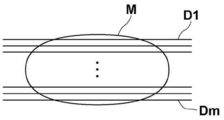
再構成部34は、トモシンセシス撮影により取得された複数の投影画像Giを再構成することにより、乳房Mの所望とする断層面を強調した断層画像を生成する。具体的には、再構成部34は、単純逆投影法あるいはフィルタ逆投影法等の周知の逆投影法等を用いて複数の投影画像Giを再構成して、図8に示すように、乳房Mの複数の断層面のそれぞれにおける複数の断層画像Dj(j=1~m)を生成する。この際、乳房Mを含む3次元空間における3次元の座標位置が設定され、設定された3次元の座標位置に対して、複数の投影画像Giの対応する画素位置の画素値が再構成されて、その座標位置の画素値が算出される。
表示制御部35は、第1の撮影により取得された第1の乳房画像、および撮影モードに応じた第2の撮影により取得された第2の乳房画像を表示部3に表示する。第2の乳房画像を表示するに際して、表示制御部35は、撮影モードが単純撮影の場合には、単純2次元画像を表示部3に表示する。表示制御部35は、撮影モードがトモシンセシス撮影の場合には、断層画像を表示部3に表示する。表示制御部35は、撮影モードが組み合わせ撮影の場合には、単純2次元画像および断層画像を表示部3に表示する。
通知部36は、撮影モードがトモシンセシス撮影の場合、および組み合わせ撮影の場合、撮影モードおよび第2の撮影の残り時間の少なくとも一方を、マンモグラフィ装置10に設けられた表示部40、および表示部3に表示することにより通知する。本実施形態においては、撮影モードおよび第2の撮影の残り時間の双方を通知する。図9は表示部40に表示された通知を示す図である。図9に示すように表示部40には、撮影モードとして「トモシンセシス撮影」が、残り時間として「10秒」が表示される。残り時間は撮影が進むにつれてカウントダウンされ、第2の撮影が完了すると、残り時間は0となる。また、表示部3にも同様の通知が行われる。なお、残り時間として数値に代えて、残り時間を表すバーを表示してもよい。
なお、撮影モードが単純撮影の場合に、撮影モードおよび第2の撮影の残り時間の少なくとも一方を通知するようにしてもよい。
次いで、本実施形態において行われる処理について説明する。図10は本実施形態において行われる処理を示すフローチャートである。なお、乳房Mの撮影台13へのポジショニングは完了しているものとする。操作者がプレ撮影の指示を入力部4から行うことにより処理が開始され、画像取得部31がマンモグラフィ装置10に第1の撮影を行わせて、第1の乳房画像MG1を取得する(ステップST1)。この際、撮影スイッチ5は操作者により押され、ポジショニングのやり直しがない限り、その状態が第2の撮影が終了するまで維持される。
次いで、3次元情報導出部32が、第1の乳房画像MG1に含まれる乳腺の3次元情報を導出する(ステップST2)。そして、撮影モード設定部33が、3次元情報に基づいて、乳房Mの第2の撮影のための撮影モードを設定する(ステップST3)。また、通知部36が、設定された撮影モードおよび第2の撮影の残り時間を通知する(ステップST4)。さらに、画像取得部31が、設定された撮影モードに基づく第2の撮影を行い、第2の乳房画像を取得する(ステップST5)。そして、表示制御部35が、第2の乳房画像を表示部3に表示し(ステップST6)、処理を終了する。操作者は通知部36による通知を見て、撮影が終了したことを確認してから、撮影スイッチ5から手を離すことができる。
なお、第1の撮影時における放射線源16の位置が基準線源位置Scである場合において、撮影モードが単純撮影に設定された場合には、放射線源16を移動させることなく、第2の撮影を行えばよい。第1の撮影時における放射線源16の位置が基準線源位置Scである場合において、撮影モードがトモシンセシス撮影に設定された場合には、放射線源16を線源位置S1に移動した後に、第2の撮影を行えばよい。この場合、放射線源16の移動中に、第1の撮影条件に従って、フィルタおよびターゲットを変更し、グリッド20を退避させればよい。第1の撮影時における放射線源16の位置が基準線源位置Scである場合において、撮影モードが組み合わせ撮影に設定された場合には、先に単純撮影を行い、放射線源16を線源位置S1に移動した後に、第2の撮影を行えばよい。
また、第1の撮影時における放射線源16の位置が線源位置S1である場合において、撮影モードが単純撮影に設定された場合には、放射線源16を基準線源位置Scに移動した後に、第2の撮影を行えばよい。この場合、放射線源16の移動中に、第2の撮影条件に従って、フィルタおよびターゲットを変更し、グリッド20を挿入すればよい。第1の撮影時における放射線源16の位置が線源位置S1である場合において、撮影モードがトモシンセシス撮影に設定された場合には、放射線源16を移動させることなく、第2の撮影を行えばよい。第1の撮影時における放射線源16の位置が線源位置S1である場合において、撮影モードが組み合わせ撮影に設定された場合には、先にトモシンセシス撮影を行い、トモシンセシス撮影の終了後、放射線源16を基準線源位置Scに移動した後に、第2の撮影を行えばよい。
このように、本実施形態においては、第1の撮影により取得された第1の乳房画像に含まれる乳腺の3次元情報に基づいて、乳房Mの第2の撮影のための撮影モードを設定し、設定された撮影モードに基づく第2の撮影によって、第1の撮影と同一ポジショニングの乳房を撮影することにより、第2の乳房画像を取得するようにした。ここで、乳腺の3次元情報は、乳房画像における広がりの方向の情報のみではなく、撮影時における乳房の厚さ方向の情報も含む。このため、乳腺の3次元情報は、乳房Mに含まれる乳腺の分布をより適切に表すものとなる。したがって、本実施形態によれば、乳房Mの撮影モードを適切に設定することができる。
また、乳房Mの厚さにも基づいて撮影モードを設定することにより、より適切に撮影モードを設定することができる。
ここで、マンモグラフィ装置10においては、乳房Mを圧迫して撮影を行うため、患者の負担が大きい。このため、現在どのような撮影が行われているのか分からないと、乳房Mを圧迫した状態がいつまで続くか分からないことから、患者は不安となる。また、操作者は、撮影が終了する前に撮影スイッチ5から手を離してしまうと撮影が中断されてしまうため、撮影中は撮影スイッチ5から手を離すことができない。しかしながら、撮影が終了するタイミングが分からないと、いつまで撮影スイッチ5を押し続ければよいのか分からない。
本実施形態においては、設定された撮影モードおよび第2の撮影の残り時間を通知するようにした。このため、患者は、現在の撮影モードおよび撮影が終了するまでの時間を知ることができ、これにより、患者の不安を軽減することができる。また、撮影者は、通知によって撮影が終了したタイミングを知ることができるため、安心して撮影スイッチ5から手を離すことができる。
なお、上記実施形態においては、放射線は、とくに限定されるものではなく、X線の他、α線またはγ線等を適用することができる。
また、上記実施形態においては、通知部36は表示部3および表示部40に通知を表示しているが、これに限定されるものではない。通知部36は、表示部3または表示部40に通知を表示するようにしてもよい。また、表示に変えてまたは表示に加えて、音声による通知を行うようにしてもよい。
また、上記実施形態において、例えば、画像取得部31、3次元情報導出部32、撮影モード設定部33、再構成部34、表示制御部35および通知部36といった各種の処理を実行する処理部(Processing Unit)のハードウェア的な構造としては、次に示す各種のプロセッサ(Processor)を用いることができる。上記各種のプロセッサには、上述したように、ソフトウェア(プログラム)を実行して各種の処理部として機能する汎用的なプロセッサであるCPUに加えて、FPGA(Field Programmable Gate Array)等の製造後に回路構成を変更可能なプロセッサであるプログラマブルロジックデバイス(Programmable Logic Device :PLD)、ASIC(Application Specific Integrated Circuit)等の特定の処理を実行させるために専用に設計された回路構成を有するプロセッサである専用電気回路等が含まれる。
1つの処理部は、これらの各種のプロセッサのうちの1つで構成されてもよいし、同種または異種の2つ以上のプロセッサの組み合わせ(例えば、複数のFPGAの組み合わせまたはCPUとFPGAとの組み合わせ)で構成されてもよい。また、複数の処理部を1つのプロセッサで構成してもよい。
複数の処理部を1つのプロセッサで構成する例としては、第1に、クライアントおよびサーバ等のコンピュータに代表されるように、1つ以上のCPUとソフトウェアとの組み合わせで1つのプロセッサを構成し、このプロセッサが複数の処理部として機能する形態がある。第2に、システムオンチップ(System On Chip:SoC)等に代表されるように、複数の処理部を含むシステム全体の機能を1つのIC(Integrated Circuit)チップで実現するプロセッサを使用する形態がある。このように、各種の処理部は、ハードウェア的な構造として、上記各種のプロセッサの1つ以上を用いて構成される。
さらに、これらの各種のプロセッサのハードウェア的な構造としては、より具体的には、半導体素子等の回路素子を組み合わせた電気回路(Circuitry)を用いることができる。
1 放射線画像撮影システム
2 コンソール
3 表示部
4 入力部
5 撮影スイッチ
10 マンモグラフィ装置
15 放射線検出器
16 放射線源
17 圧迫板
20 散乱線除去グリッド
21 CPU
22 メモリ
23 ストレージ
31 画像取得部
32 3次元情報導出部
33 撮影モード設定部
34 再構成部
35 表示制御部
36 通知部
40 表示部
50 関心領域
Dj(j=1~m) 断層画像
Gi(i=1~n) 投影画像
M、M11、M12、M13 乳房
MG1 第1の乳房画像
Si(i=1~n) 線源位置
Sc 基準線源位置
2 コンソール
3 表示部
4 入力部
5 撮影スイッチ
10 マンモグラフィ装置
15 放射線検出器
16 放射線源
17 圧迫板
20 散乱線除去グリッド
21 CPU
22 メモリ
23 ストレージ
31 画像取得部
32 3次元情報導出部
33 撮影モード設定部
34 再構成部
35 表示制御部
36 通知部
40 表示部
50 関心領域
Dj(j=1~m) 断層画像
Gi(i=1~n) 投影画像
M、M11、M12、M13 乳房
MG1 第1の乳房画像
Si(i=1~n) 線源位置
Sc 基準線源位置
Claims (13)
- 第1の撮影によって乳房を撮影することにより、第1の乳房画像を取得する画像取得部と、
前記第1の乳房画像に含まれる乳腺の3次元情報を導出する3次元情報導出部と、
前記3次元情報に基づいて、前記乳房の第2の撮影のための撮影モードを設定する撮影モード設定部とを備え、
前記画像取得部は、設定された撮影モードに基づく前記第2の撮影によって、前記第1の撮影と同一ポジショニングの乳房を撮影することにより、第2の乳房画像を取得する撮影制御装置。 - 前記3次元情報導出部は、前記乳房の関心領域における前記乳腺の体積、前記乳腺の体積の割合、および前記乳腺の厚さのいずれかを前記3次元情報として導出する請求項1に記載の撮影制御装置。
- 前記関心領域は、前記乳房の全体領域である請求項2に記載の撮影制御装置。
- 前記関心領域は、前記乳房の厚さに対して前記乳腺が予め定められた割合以上存在する領域である請求項2に記載の撮影制御装置。
- 前記撮影モード設定部は、前記3次元情報に基づいて、単純2次元撮影、トモシンセシス撮影、および単純撮影とトモシンセシス撮影との組み合わせ撮影のいずれかを撮影モードとして設定する請求項2から4のいずれか1項に記載の撮影制御装置。
- 前記撮影モード設定部は、さらに前記乳房の厚さにも基づいて前記撮影モードを設定する請求項5に記載の撮影制御装置。
- 前記撮影モード設定部は、前記乳腺の体積または前記乳腺の体積の割合が予め定められたしきい値以下の場合は、前記撮影モードを前記単純2次元撮影に設定し、前記乳腺の体積または前記乳腺の体積の割合が前記しきい値より大きい場合は、前記撮影モードを前記トモシンセシス撮影に設定する請求項5に記載の撮影制御装置。
- 前記撮影モード設定部は、前記乳腺の体積または前記乳腺の体積の割合が予め定められた第1のしきい値以下であり、かつ前記乳房の厚さが予め定められた第2のしきい値以下の場合は、前記撮影モードを前記単純2次元撮影に設定し、前記乳腺の体積または前記乳腺の体積の割合が前記第1のしきい値より大きく、かつ前記乳房の厚さが前記第2のしきい値以下の場合は、前記撮影モードを前記トモシンセシス撮影に設定し、前記乳房の厚さが前記第2のしきい値より大きい場合は、前記撮影モードを前記組み合わせ撮影に設定する請求項6に記載の撮影制御装置。
- 前記撮影モード設定部は、前記乳腺の厚さが予め定められたしきい値以下の場合は、前記撮影モードを前記単純2次元撮影に設定し、前記乳腺の厚さが前記しきい値より大きい場合は、前記撮影モードを前記トモシンセシス撮影に設定する請求項5に記載の撮影制御装置。
- 前記撮影モード設定部は、前記乳腺の厚さが予め定められた第3のしきい値以下であり、かつ前記乳房の厚さが予め定められた第4のしきい値以下の場合は、前記撮影モードを前記単純2次元撮影に設定し、前記乳腺の厚さが前記第3のしきい値より大きく、かつ前記乳房の厚さが前記第4のしきい値以下の場合は、前記撮影モードを前記トモシンセシス撮影に設定し、前記乳房の厚さが前記第4のしきい値より大きい場合は、前記撮影モードを前記組み合わせ撮影に設定する請求項6に記載の撮影制御装置。
- 前記設定された撮影モードおよび該撮影モードによる前記第2の撮影の残り時間の少なくとも一方を通知する通知部をさらに備えた請求項1から10のいずれか1項に記載の撮影制御装置。
- 第1の撮影によって乳房を撮影することにより、第1の乳房画像を取得し、
前記第1の乳房画像に含まれる乳腺の3次元情報を導出し、
前記3次元情報に基づいて、前記乳房の第2の撮影のための撮影モードを設定し、
設定された撮影モードに基づく前記第2の撮影によって、前記第1の撮影と同一ポジショニングの乳房を撮影することにより、第2の乳房画像を取得する撮影制御方法。 - 第1の撮影によって乳房を撮影することにより、第1の乳房画像を取得する手順と、
前記第1の乳房画像に含まれる乳腺の3次元情報を導出する手順と、
前記3次元情報に基づいて、前記乳房の第2の撮影のための撮影モードを設定する手順と、
設定された撮影モードに基づく前記第2の撮影によって、前記第1の撮影と同一ポジショニングの乳房を撮影することにより、第2の乳房画像を取得する手順とをコンピュータに実行させる撮影制御プログラム。
Priority Applications (3)
| Application Number | Priority Date | Filing Date | Title |
|---|---|---|---|
| JP2021508713A JP7169430B2 (ja) | 2019-03-27 | 2019-11-12 | 撮影制御装置、方法およびプログラム |
| EP19921770.4A EP3949859B1 (en) | 2019-03-27 | 2019-11-12 | Apparatus, method, and program for controlling photographing |
| US17/464,717 US11883221B2 (en) | 2019-03-27 | 2021-09-02 | Imaging control apparatus, imaging control method, and imaging control program |
Applications Claiming Priority (2)
| Application Number | Priority Date | Filing Date | Title |
|---|---|---|---|
| JP2019-060371 | 2019-03-27 | ||
| JP2019060371 | 2019-03-27 |
Related Child Applications (1)
| Application Number | Title | Priority Date | Filing Date |
|---|---|---|---|
| US17/464,717 Continuation US11883221B2 (en) | 2019-03-27 | 2021-09-02 | Imaging control apparatus, imaging control method, and imaging control program |
Publications (1)
| Publication Number | Publication Date |
|---|---|
| WO2020194844A1 true WO2020194844A1 (ja) | 2020-10-01 |
Family
ID=72610891
Family Applications (1)
| Application Number | Title | Priority Date | Filing Date |
|---|---|---|---|
| PCT/JP2019/044391 Ceased WO2020194844A1 (ja) | 2019-03-27 | 2019-11-12 | 撮影制御装置、方法およびプログラム |
Country Status (4)
| Country | Link |
|---|---|
| US (1) | US11883221B2 (ja) |
| EP (1) | EP3949859B1 (ja) |
| JP (1) | JP7169430B2 (ja) |
| WO (1) | WO2020194844A1 (ja) |
Cited By (3)
| Publication number | Priority date | Publication date | Assignee | Title |
|---|---|---|---|---|
| JP2022148639A (ja) * | 2021-03-24 | 2022-10-06 | 富士フイルム株式会社 | 画像処理装置、放射線画像撮影システム、画像処理方法、及び画像処理プログラム |
| JP2023115845A (ja) * | 2022-02-08 | 2023-08-21 | キヤノンメディカルシステムズ株式会社 | マンモグラフィ装置 |
| US20240206837A1 (en) * | 2022-12-22 | 2024-06-27 | Fujifilm Corporation | Mammography apparatus |
Families Citing this family (1)
| Publication number | Priority date | Publication date | Assignee | Title |
|---|---|---|---|---|
| JP2024128889A (ja) * | 2023-03-10 | 2024-09-24 | 富士フイルム株式会社 | 画像処理装置、画像撮影システム、画像処理方法、画像処理プログラム |
Citations (6)
| Publication number | Priority date | Publication date | Assignee | Title |
|---|---|---|---|---|
| JP2007050264A (ja) | 2005-08-15 | 2007-03-01 | Hologic Inc | 患者胸部のx線マンモグラフィ/トモシンセシス |
| JP2007236804A (ja) | 2006-03-10 | 2007-09-20 | Toshiba Corp | 乳房撮影用x線診断装置及び乳房撮影用x線診断プログラム |
| JP2009072410A (ja) * | 2007-09-21 | 2009-04-09 | Toshiba Corp | 複合画像診断装置 |
| JP2012135444A (ja) | 2010-12-27 | 2012-07-19 | Fujifilm Corp | 撮影制御装置および撮影制御方法 |
| US20140133626A1 (en) * | 2012-11-09 | 2014-05-15 | Samsung Electronics Co., Ltd. | X-ray imaging apparatus and x-ray imaging method |
| JP2017051752A (ja) | 2016-12-20 | 2017-03-16 | 富士フイルム株式会社 | 放射線画像撮影装置および方法 |
Family Cites Families (18)
| Publication number | Priority date | Publication date | Assignee | Title |
|---|---|---|---|---|
| US7123684B2 (en) * | 2002-11-27 | 2006-10-17 | Hologic, Inc. | Full field mammography with tissue exposure control, tomosynthesis, and dynamic field of view processing |
| US10638994B2 (en) * | 2002-11-27 | 2020-05-05 | Hologic, Inc. | X-ray mammography with tomosynthesis |
| DE102006051778A1 (de) | 2006-11-02 | 2008-05-15 | Siemens Ag | Verfahren und Einrichtung zur Anzeige eines im Rahmen einer Mammographie aufgenommenen Röntgenbildes |
| JP5052123B2 (ja) * | 2006-12-27 | 2012-10-17 | 富士フイルム株式会社 | 医用撮像システム及び方法 |
| JP5481038B2 (ja) * | 2007-04-05 | 2014-04-23 | 株式会社東芝 | 超音波診断装置、乳房イメージングシステム及び乳房イメージングプログラム |
| DE102010035920A1 (de) * | 2010-08-31 | 2012-03-01 | Siemens Aktiengesellschaft | Verfahren zur Darstellung eines vorbestimmten Volumenabschnitts eines Untersuchungsobjekts mittels eines Tomosynthesegeräts und entsprechendes Tomosynthesegerät |
| US9168013B2 (en) * | 2010-12-13 | 2015-10-27 | Koninklijke Philips N.V. | Breast density assessment |
| JP5844296B2 (ja) * | 2012-06-11 | 2016-01-13 | 富士フイルム株式会社 | 放射線画像処理装置および方法 |
| JP2014061232A (ja) | 2012-09-24 | 2014-04-10 | Toshiba Corp | 乳房x線撮影装置 |
| WO2014195669A1 (en) * | 2013-06-06 | 2014-12-11 | Matakina Technology Ltd | A method of reconstruction of an object from projection views |
| KR102264462B1 (ko) * | 2013-10-09 | 2021-06-15 | 홀로직, 인크. | 편평화된 유방의 두께 방향을 포함하는 공간 해상도를 향상시키는 x선 유방 영상합성 |
| JP2017047103A (ja) | 2015-09-04 | 2017-03-09 | キヤノン株式会社 | 制御装置、乳房撮影システム、乳房撮影装置の制御方法 |
| JP6656199B2 (ja) | 2017-03-30 | 2020-03-04 | 富士フイルム株式会社 | マンモグラフィ装置 |
| JP7022543B2 (ja) * | 2017-09-11 | 2022-02-18 | キヤノン株式会社 | 乳房撮影装置、乳房撮影装置の制御方法及びプログラム |
| WO2019227051A2 (en) * | 2018-05-25 | 2019-11-28 | Hologic, Inc. | Systems and methods for pivoting compression paddles |
| JP7053102B2 (ja) * | 2018-09-27 | 2022-04-12 | 富士フイルム株式会社 | 情報処理装置とその作動プログラムおよび作動方法、並びに乳房撮影装置 |
| US12059280B2 (en) * | 2020-02-25 | 2024-08-13 | GE Precision Healthcare LLC | Methods and systems for dynamic collimation |
| KR102447341B1 (ko) * | 2020-04-10 | 2022-09-26 | 주식회사 뷰웍스 | 유방 촬영 장치 및 방법 |
-
2019
- 2019-11-12 JP JP2021508713A patent/JP7169430B2/ja active Active
- 2019-11-12 EP EP19921770.4A patent/EP3949859B1/en active Active
- 2019-11-12 WO PCT/JP2019/044391 patent/WO2020194844A1/ja not_active Ceased
-
2021
- 2021-09-02 US US17/464,717 patent/US11883221B2/en active Active
Patent Citations (6)
| Publication number | Priority date | Publication date | Assignee | Title |
|---|---|---|---|---|
| JP2007050264A (ja) | 2005-08-15 | 2007-03-01 | Hologic Inc | 患者胸部のx線マンモグラフィ/トモシンセシス |
| JP2007236804A (ja) | 2006-03-10 | 2007-09-20 | Toshiba Corp | 乳房撮影用x線診断装置及び乳房撮影用x線診断プログラム |
| JP2009072410A (ja) * | 2007-09-21 | 2009-04-09 | Toshiba Corp | 複合画像診断装置 |
| JP2012135444A (ja) | 2010-12-27 | 2012-07-19 | Fujifilm Corp | 撮影制御装置および撮影制御方法 |
| US20140133626A1 (en) * | 2012-11-09 | 2014-05-15 | Samsung Electronics Co., Ltd. | X-ray imaging apparatus and x-ray imaging method |
| JP2017051752A (ja) | 2016-12-20 | 2017-03-16 | 富士フイルム株式会社 | 放射線画像撮影装置および方法 |
Non-Patent Citations (2)
| Title |
|---|
| RALPH HIGHNAM ET AL.: "Robust Breast composition Measurement-Volpara", IWDM2010, LNCS, vol. 6136, 2010, pages 342 - 349, XP002604953 |
| See also references of EP3949859A4 |
Cited By (5)
| Publication number | Priority date | Publication date | Assignee | Title |
|---|---|---|---|---|
| JP2022148639A (ja) * | 2021-03-24 | 2022-10-06 | 富士フイルム株式会社 | 画像処理装置、放射線画像撮影システム、画像処理方法、及び画像処理プログラム |
| US12133756B2 (en) | 2021-03-24 | 2024-11-05 | Fujifilm Corporation | Image processing device, radiography system, image processing method, and image processing program |
| JP7607485B2 (ja) | 2021-03-24 | 2024-12-27 | 富士フイルム株式会社 | 画像処理装置、放射線画像撮影システム、画像処理方法、及び画像処理プログラム |
| JP2023115845A (ja) * | 2022-02-08 | 2023-08-21 | キヤノンメディカルシステムズ株式会社 | マンモグラフィ装置 |
| US20240206837A1 (en) * | 2022-12-22 | 2024-06-27 | Fujifilm Corporation | Mammography apparatus |
Also Published As
| Publication number | Publication date |
|---|---|
| JP7169430B2 (ja) | 2022-11-10 |
| EP3949859B1 (en) | 2025-03-26 |
| JPWO2020194844A1 (ja) | 2020-10-01 |
| US20210393225A1 (en) | 2021-12-23 |
| US11883221B2 (en) | 2024-01-30 |
| EP3949859A1 (en) | 2022-02-09 |
| EP3949859A4 (en) | 2022-05-18 |
Similar Documents
| Publication | Publication Date | Title |
|---|---|---|
| JP7122886B2 (ja) | 撮影制御装置、方法およびプログラム | |
| JP6682150B2 (ja) | 乳腺量取得装置、方法およびプログラム | |
| US11883221B2 (en) | Imaging control apparatus, imaging control method, and imaging control program | |
| JP2017143943A (ja) | 放射線画像処理装置、方法およびプログラム | |
| JP7203705B2 (ja) | 画像処理装置、方法およびプログラム、並びに画像表示装置、方法およびプログラム | |
| JP7326070B2 (ja) | 画像表示装置、方法およびプログラム、画像管理装置、方法およびプログラム | |
| JP5669799B2 (ja) | 画像処理装置、放射線画像撮影システム、画像処理プログラム、及び画像処理方法 | |
| JP7384990B2 (ja) | 画像管理装置、方法およびプログラム | |
| US11484275B2 (en) | Image processing apparatus, method, and program | |
| JP7209599B2 (ja) | 画像処理装置、方法およびプログラム | |
| JP7270781B2 (ja) | 画像設定装置、画像設定装置の作動方法および画像設定プログラム | |
| US12327352B2 (en) | Image setting device, image setting method, and image setting program | |
| US11779297B2 (en) | Control device, control method, and control program | |
| JP7208874B2 (ja) | 撮影制御装置、方法およびプログラム | |
| US12597126B2 (en) | Image setting device, image setting method, and image setting program | |
| US11779299B2 (en) | Control device, control method, and control program | |
| JP2025040874A (ja) | 画像処理装置、放射線画像撮影システム及びプログラム | |
| JP2013046708A (ja) | 乳房x線撮影装置、画像処理装置、及び画像処理方法 |
Legal Events
| Date | Code | Title | Description |
|---|---|---|---|
| 121 | Ep: the epo has been informed by wipo that ep was designated in this application |
Ref document number: 19921770 Country of ref document: EP Kind code of ref document: A1 |
|
| ENP | Entry into the national phase |
Ref document number: 2021508713 Country of ref document: JP Kind code of ref document: A |
|
| NENP | Non-entry into the national phase |
Ref country code: DE |
|
| ENP | Entry into the national phase |
Ref document number: 2019921770 Country of ref document: EP Effective date: 20211027 |