WO2020194844A1 - Dispositif, procédé et programme de commande photographique - Google Patents
Dispositif, procédé et programme de commande photographique Download PDFInfo
- Publication number
- WO2020194844A1 WO2020194844A1 PCT/JP2019/044391 JP2019044391W WO2020194844A1 WO 2020194844 A1 WO2020194844 A1 WO 2020194844A1 JP 2019044391 W JP2019044391 W JP 2019044391W WO 2020194844 A1 WO2020194844 A1 WO 2020194844A1
- Authority
- WO
- WIPO (PCT)
- Prior art keywords
- imaging
- breast
- shooting
- mammary gland
- image
- Prior art date
- Legal status (The legal status is an assumption and is not a legal conclusion. Google has not performed a legal analysis and makes no representation as to the accuracy of the status listed.)
- Ceased
Links
Images


Classifications
-
- A—HUMAN NECESSITIES
- A61—MEDICAL OR VETERINARY SCIENCE; HYGIENE
- A61B—DIAGNOSIS; SURGERY; IDENTIFICATION
- A61B6/00—Apparatus or devices for radiation diagnosis; Apparatus or devices for radiation diagnosis combined with radiation therapy equipment
- A61B6/50—Apparatus or devices for radiation diagnosis; Apparatus or devices for radiation diagnosis combined with radiation therapy equipment specially adapted for specific body parts; specially adapted for specific clinical applications
- A61B6/502—Apparatus or devices for radiation diagnosis; Apparatus or devices for radiation diagnosis combined with radiation therapy equipment specially adapted for specific body parts; specially adapted for specific clinical applications for diagnosis of breast, i.e. mammography
-
- A—HUMAN NECESSITIES
- A61—MEDICAL OR VETERINARY SCIENCE; HYGIENE
- A61B—DIAGNOSIS; SURGERY; IDENTIFICATION
- A61B6/00—Apparatus or devices for radiation diagnosis; Apparatus or devices for radiation diagnosis combined with radiation therapy equipment
- A61B6/02—Arrangements for diagnosis sequentially in different planes; Stereoscopic radiation diagnosis
- A61B6/025—Tomosynthesis
-
- A—HUMAN NECESSITIES
- A61—MEDICAL OR VETERINARY SCIENCE; HYGIENE
- A61B—DIAGNOSIS; SURGERY; IDENTIFICATION
- A61B6/00—Apparatus or devices for radiation diagnosis; Apparatus or devices for radiation diagnosis combined with radiation therapy equipment
- A61B6/46—Arrangements for interfacing with the operator or the patient
- A61B6/461—Displaying means of special interest
- A61B6/463—Displaying means of special interest characterised by displaying multiple images or images and diagnostic data on one display
-
- A—HUMAN NECESSITIES
- A61—MEDICAL OR VETERINARY SCIENCE; HYGIENE
- A61B—DIAGNOSIS; SURGERY; IDENTIFICATION
- A61B6/00—Apparatus or devices for radiation diagnosis; Apparatus or devices for radiation diagnosis combined with radiation therapy equipment
- A61B6/46—Arrangements for interfacing with the operator or the patient
- A61B6/467—Arrangements for interfacing with the operator or the patient characterised by special input means
- A61B6/469—Arrangements for interfacing with the operator or the patient characterised by special input means for selecting a region of interest [ROI]
-
- A—HUMAN NECESSITIES
- A61—MEDICAL OR VETERINARY SCIENCE; HYGIENE
- A61B—DIAGNOSIS; SURGERY; IDENTIFICATION
- A61B6/00—Apparatus or devices for radiation diagnosis; Apparatus or devices for radiation diagnosis combined with radiation therapy equipment
- A61B6/54—Control of apparatus or devices for radiation diagnosis
- A61B6/545—Control of apparatus or devices for radiation diagnosis involving automatic set-up of acquisition parameters
-
- G—PHYSICS
- G06—COMPUTING OR CALCULATING; COUNTING
- G06T—IMAGE DATA PROCESSING OR GENERATION, IN GENERAL
- G06T7/00—Image analysis
- G06T7/0002—Inspection of images, e.g. flaw detection
- G06T7/0012—Biomedical image inspection
-
- G—PHYSICS
- G06—COMPUTING OR CALCULATING; COUNTING
- G06V—IMAGE OR VIDEO RECOGNITION OR UNDERSTANDING
- G06V10/00—Arrangements for image or video recognition or understanding
- G06V10/20—Image preprocessing
- G06V10/25—Determination of region of interest [ROI] or a volume of interest [VOI]
-
- A—HUMAN NECESSITIES
- A61—MEDICAL OR VETERINARY SCIENCE; HYGIENE
- A61B—DIAGNOSIS; SURGERY; IDENTIFICATION
- A61B6/00—Apparatus or devices for radiation diagnosis; Apparatus or devices for radiation diagnosis combined with radiation therapy equipment
- A61B6/04—Positioning of patients; Tiltable beds or the like
- A61B6/0407—Supports, e.g. tables or beds, for the body or parts of the body
- A61B6/0414—Supports, e.g. tables or beds, for the body or parts of the body with compression means
-
- A—HUMAN NECESSITIES
- A61—MEDICAL OR VETERINARY SCIENCE; HYGIENE
- A61B—DIAGNOSIS; SURGERY; IDENTIFICATION
- A61B6/00—Apparatus or devices for radiation diagnosis; Apparatus or devices for radiation diagnosis combined with radiation therapy equipment
- A61B6/46—Arrangements for interfacing with the operator or the patient
- A61B6/461—Displaying means of special interest
- A61B6/466—Displaying means of special interest adapted to display 3D data
-
- A—HUMAN NECESSITIES
- A61—MEDICAL OR VETERINARY SCIENCE; HYGIENE
- A61B—DIAGNOSIS; SURGERY; IDENTIFICATION
- A61B6/00—Apparatus or devices for radiation diagnosis; Apparatus or devices for radiation diagnosis combined with radiation therapy equipment
- A61B6/48—Diagnostic techniques
- A61B6/488—Diagnostic techniques involving pre-scan acquisition
-
- G—PHYSICS
- G06—COMPUTING OR CALCULATING; COUNTING
- G06T—IMAGE DATA PROCESSING OR GENERATION, IN GENERAL
- G06T2207/00—Indexing scheme for image analysis or image enhancement
- G06T2207/30—Subject of image; Context of image processing
- G06T2207/30004—Biomedical image processing
- G06T2207/30068—Mammography; Breast
Definitions
- This disclosure relates to imaging control devices, methods and programs.
- mammography radiographic imaging device
- the breast is placed on the imaging table and the image is taken while being compressed by the compression plate.
- the breast is mainly composed of mammary gland tissue and adipose tissue, and it is important for diagnosis to detect lesions such as tumors and calcification hidden in the mammary gland tissue. Therefore, the radiographic image (breast image) of the breast taken by mammography is image-processed by a dedicated operation terminal or the like and then used for diagnosis by a doctor. The doctor examines the presence or absence of an abnormal part by displaying the breast image on a display or the like and interpreting the image.
- the breast is a mixture of mammary gland tissue and adipose tissue.
- the abnormal part may be hidden by the mammary gland in the breast image, and as a result, the abnormal part may be difficult to see.
- a tomographic image in which a desired tomographic surface is emphasized is obtained by moving a radiation source and irradiating the breast with radiation from a plurality of source positions to take an image, and adding a plurality of projected images obtained thereby.
- Produced tomosynthesis imaging has been proposed.
- tomosynthesis imaging multiple source positions can be moved by moving the radiation source parallel to the radiation detector or in a circular or elliptical arc, depending on the characteristics of the imaging device and the required tomographic image.
- a plurality of projected images are acquired by photographing the breast, and these projected images are reconstructed by using a back projection method such as a simple back projection method or a filter back projection method to generate a tomographic image.
- a scattered radiation removal grid (hereinafter simply referred to as a grid) is used in order to prevent a decrease in contrast due to the influence of scattered radiation generated in the subject.
- a grid a scattered radiation removal grid
- the angle of incidence of the radiation on the radiation detector is different at each imaging position. Therefore, when photographing using the grid, depending on the position of the radiation source, radiation may be blocked by the grid, and the amount of radiation reaching the radiation detector may be reduced. Therefore, the grid is not used when performing tomosynthesis imaging.
- the noise of the projected image and the tomographic image will increase due to the influence of scattered rays, and the image quality will deteriorate.
- the degree of radiation scattering becomes large, and the noise caused by the scattered radiation increases.
- relatively low-density pixels in the entire region included in the breast image or in a predetermined region are regarded as mammary gland pixels, and the entire region included in the breast image or in advance.
- the ratio of the area of the mammary gland area in the defined area is calculated as the amount of mammary gland.
- an appropriate imaging mode may not be selected by the method based on the ratio of the area of the mammary gland region.
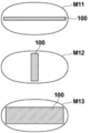
- the breast M11 of FIG. 11 when the mammary gland 100 is thin and widely distributed in the breast, the ratio of the area of the mammary gland becomes large in the method described in Japanese Patent Application Laid-Open No. 2012-135444.
- Tomosynthesis shooting is selected as the shooting mode.
- the breast M11 is a tomosynthesis capable of separating the overlap in the breast thickness direction as compared with the case where the mammary glands 100 are also distributed in the breast thickness direction as in the case of the breast M12 or the breast M13 shown in FIG.
- the advantage of shooting is small. Tomosynthesis imaging is performed multiple times with the breast compressed. Therefore, in the case of the breast M11 as shown in FIG. 11, the burden on the patient and the exposure dose are smaller when the simple imaging is performed.
- the present disclosure has been made in view of the above circumstances, and an object of the present disclosure is to enable the appropriate setting of the breast imaging mode.
- the imaging control device includes an image acquisition unit that acquires a first breast image by photographing the breast by the first imaging.
- a three-dimensional information derivation unit that derives three-dimensional information of the mammary gland included in the first breast image, It is equipped with a imaging mode setting unit that sets the imaging mode for the second imaging of the breast based on the three-dimensional information.
- the image acquisition unit acquires a second breast image by imaging a breast having the same positioning as the first imaging by the second imaging based on the set imaging mode.
- the three-dimensional information derivation unit derives any one of the volume of the mammary gland, the ratio of the volume of the mammary gland, and the thickness of the mammary gland in the region of interest of the breast as three-dimensional information. There may be.
- the region of interest may be the entire region of the breast.
- the region of interest may be a region in which the mammary gland exists in a predetermined ratio or more with respect to the thickness of the breast.
- the shooting mode setting unit sets any of simple two-dimensional shooting, tomosynthesis shooting, and combined shooting of simple shooting and tomosynthesis shooting as the shooting mode based on the three-dimensional information. It may be something to do.
- the imaging mode setting unit may further set the imaging mode based on the thickness of the breast.
- the imaging mode setting unit sets the imaging mode to simple two-dimensional imaging when the volume of the mammary gland or the ratio of the volume of the mammary gland is equal to or less than a predetermined threshold value. If the volume of the mammary gland or the ratio of the volume of the mammary gland is larger than the threshold value, the imaging mode may be set to tomosynthesis imaging.
- the threshold value may be set experimentally as appropriate according to the volume of the mammary gland or the ratio of the volume of the mammary gland.
- the volume of the mammary gland or the ratio of the volume of the mammary gland is equal to or less than a predetermined first threshold value, and the thickness of the breast is predetermined. If it is less than or equal to the second threshold, the imaging mode is set to simple two-dimensional imaging, the volume of the breast or the ratio of the volume of the breast is larger than the first threshold, and the thickness of the breast is the second. If it is less than or equal to the threshold value of, the imaging mode may be set to tomosynthesis imaging, and if the breast thickness is larger than the second threshold value, the imaging mode may be set to combined imaging.
- the first threshold value may be appropriately set experimentally according to the volume of the mammary gland or the ratio of the volume of the mammary gland.
- the second threshold value may be set experimentally as appropriate according to the thickness of the breast.
- the imaging mode setting unit sets the imaging mode to simple two-dimensional imaging, and the thickness of the mammary gland is determined. If it is larger than the value, the shooting mode may be set to tomosynthesis shooting.
- the threshold value may be set experimentally as appropriate according to the thickness of the mammary gland.
- the thickness of the breast gland is equal to or less than a predetermined third threshold value, and the thickness of the breast is predetermined. If it is less than or equal to the threshold value, set the imaging mode to simple two-dimensional imaging, and if the thickness of the breast gland is larger than the third threshold value and the thickness of the breast is less than or equal to the fourth threshold value, imaging is performed. If the mode is set to tomosynthesis imaging and the breast thickness is greater than the fourth threshold, the imaging mode may be set to combined imaging.
- the third threshold value may be set experimentally as appropriate according to the thickness of the mammary gland. Further, the fourth threshold value may be set experimentally as appropriate according to the thickness of the breast.
- the shooting control device may further include a notification unit for notifying at least one of the set shooting mode and the remaining time of the second shooting in the shooting mode.
- the imaging control method acquires a first breast image by photographing the breast by the first imaging, and obtains a first breast image. Derived the three-dimensional information of the mammary gland contained in the first breast image, Based on the 3D information, set the imaging mode for the second imaging of the breast, A second breast image is acquired by photographing a breast having the same positioning as the first imaging by the second imaging based on the set imaging mode.
- the other imaging control devices include a memory for storing an instruction to be executed by a computer and a memory.
- the processor comprises a processor configured to execute a stored instruction.
- the imaging mode of the breast can be appropriately set.
- FIG. 1 Schematic configuration diagram of a radiographic imaging system to which the imaging control device according to the embodiment of the present disclosure is applied.
- Diagram to illustrate tomosynthesis photography Diagram for explaining the setting of the region of interest in the first breast image The figure which shows the table which corresponded the relationship between 3D information and a shooting mode.
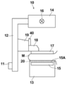
- FIG. 1 is a schematic configuration diagram of a radiation imaging system to which the imaging control device according to the embodiment of the present disclosure is applied
- FIG. 2 is a view of a mammography apparatus included in the radiation imaging system as viewed from the direction of arrow A in FIG.
- the radiographic imaging system 1 of the present embodiment includes a console 2 and a mammography apparatus 10.
- the console 2 includes a display unit 3, an input unit 4, and a shooting switch 5.
- the radiological imaging system 1 of the present embodiment is based on an instruction (imaging order) input from an external system (for example, RIS: Radiology Information System) via the console 2, and is operated by an operator such as a doctor or a radiologist.
- the mammography apparatus 10 has a function of performing tomosynthesis imaging of the breast and acquiring tomographic images at a plurality of tomographic planes of the breast.
- the mammography apparatus 10 can perform both tomosynthesis imaging and simple imaging to generate a tomographic image of the breast and a two-dimensional breast image.
- the two-dimensional breast image means a breast image acquired by simple imaging.
- the mammography apparatus 10 includes an arm portion 12 connected to a base (not shown) by a rotating shaft 11.
- An imaging table 13 is attached to one end of the arm portion 12, and an irradiation unit 14 is attached to the other end so as to face the photographing table 13.
- the arm portion 12 is configured so that only the end portion to which the radiation irradiation unit 14 is attached can be rotated, whereby the imaging table 13 can be fixed and only the radiation irradiation unit 14 can be rotated. It has become.
- the rotation of the arm portion 12 is controlled by the console 2.
- a radiation detector 15 such as a flat panel detector is provided inside the photographing table 13.
- the radiation detector 15 has a radiation detection surface 15A. Further, inside the photographing table 13, a charge amplifier that converts the charge signal read from the radiation detector 15 into a voltage signal, a correlated double sampling circuit that samples the voltage signal output from the charge amplifier, and a voltage signal.
- a circuit board or the like provided with an AD (Analog Digital) conversion unit or the like for converting the voltage into a digital signal is also installed.
- AD Analog Digital
- the radiation detector 15 is used in the present embodiment, it is not limited to the radiation detector 15 as long as it can detect the radiation and convert it into an image.
- the scattered radiation removal grid 20 is arranged so as to be able to be taken in and out between the surface of the photographing table 13 and the radiation detector 15.
- the radiation detector 15 can repeatedly record and read a radiation image, and may use a so-called direct type radiation detector that directly converts radiation such as X-rays into a charge, or radiation. You may use a so-called indirect radiation detector that once converts the visible light into visible light and then converts the visible light into a charge signal.
- the radiation image signal can be read out by turning on and off the TFT (Thin Film Transistor) switch, that is, the so-called TFT reading method, or by irradiating the read light. It is desirable to use a so-called optical reading method in which the light is read, but the present invention is not limited to this, and other materials may be used.
- the radiation source 16 is housed inside the radiation irradiation unit 14.
- the radiation source 16 emits X-rays as radiation, and the timing of irradiating the radiation from the radiation source 16 and the radiation generation conditions in the radiation source 16, that is, the selection of the material of the target and the filter, the tube voltage, the irradiation time, and the like are determined. It is controlled by the console 2.
- a compression plate 17 which is arranged above the imaging table 13 and presses and presses the breast M
- a support portion 18 which supports the compression plate 17, and a support portion 18 are vertically attached to FIGS. 1 and 2.
- a moving mechanism 19 for moving in a direction is provided.
- the distance between the compression plate 17 and the photographing table 13, that is, the compression thickness is input to the console 2.
- the moving mechanism 19 is provided with a display unit 40 such as a liquid crystal display for displaying various information directed to the patient.
- the display unit 40 displays a notification such as the remaining time until the end of shooting, which will be described later.
- the display unit 40 may have a built-in speaker that outputs sound.
- the display unit 3 is a display device such as a CRT (Cathode Ray Tube) or a liquid crystal display, and displays a first breast image and a second breast image acquired as described later, a message necessary for operation, and the like. To do.
- the display unit 3 may have a built-in speaker that outputs sound.
- the input unit 4 is composed of an input device such as a keyboard, a mouse, or a touch panel system, and receives input for operation of the mammography device 10 by an operator. It also accepts instructions for inputting various information such as shooting conditions and correcting the information necessary for shooting. In the present embodiment, each part of the mammography apparatus 10 operates according to the information input from the input unit 4 by the operator.
- the photographing switch 5 is provided from the viewpoint of safety, and a series of imaging including irradiation of radiation is executed only while the operator presses the imaging switch 5, and the operator performs the imaging switch 5. Shooting is stopped when you take your hand off.
- the shooting control program is installed on the console 2.
- the console 2 may be a workstation or a personal computer directly operated by the operator, or may be a server computer connected to them via a network.
- the shooting control program is recorded and distributed on a recording medium such as a DVD (Digital Versatile Disc) or a CD-ROM (Compact Disc Read Only Memory), and is installed in the computer from the recording medium.
- a recording medium such as a DVD (Digital Versatile Disc) or a CD-ROM (Compact Disc Read Only Memory)
- it is stored in the storage device of the server computer connected to the network or in the network storage in a state where it can be accessed from the outside, and is downloaded and installed in the computer upon request.
- FIG. 3 is a diagram showing a schematic configuration of a shooting control device realized by installing the shooting control program according to the present embodiment on the console 2.
- the photographing control device includes a CPU (Central Processing Unit) 21, a memory 22, and a storage 23 as a standard computer configuration.
- CPU Central Processing Unit
- the storage 23 is composed of a storage device such as a hard disk drive or an SSD (Solid State Drive), and stores various information including a shooting control program for driving each part of the mammography apparatus 10.
- the first breast image acquired by the first imaging and the second breast image acquired by the second imaging are also stored.
- the memory 22 temporarily stores a program or the like stored in the storage 23 in order for the CPU 21 to execute various processes.
- the imaging control program causes the mammography apparatus 10 to perform the first imaging and the second imaging described later, and acquires the first breast image and the second breast image.
- a three-dimensional information derivation process for deriving three-dimensional information of the mammary gland included in the first breast image acquired by the first imaging, and a imaging mode for the second imaging of the breast M based on the three-dimensional information.
- the imaging mode setting process for setting and the imaging mode for the second imaging are tomosynthesis imaging, by reconstructing the acquired plurality of projected images, a plurality of tomographic images at each of the plurality of tomographic planes of the breast M can be obtained.
- the display control process for displaying the second breast image acquired by imaging on the display unit 3 and the remaining time of the second imaging in the set imaging mode and imaging mode. Specify notification processing.
- the CPU 21 executes these processes according to the shooting control program, so that the computer constituting the console 2 has the image acquisition unit 31, the three-dimensional information derivation unit 32, the shooting mode setting unit 33, the reconstruction unit 34, and the display control. It functions as a unit 35 and a notification unit 36.
- the image acquisition unit 31 causes the mammography apparatus 10 to perform pre-shooting as the first shooting in order to optimize the shooting conditions for the second shooting and to set the shooting mode described later.
- the pre-imaging is an imaging in which a low dose of radiation is applied to the breast M according to the imaging conditions of the pre-imaging described later.
- the breast image acquired by the first imaging is defined as the first breast image.
- the first breast image may be displayed on the display unit 3 by the display control unit 35.
- the operator can determine whether or not the positioning of the breast M is appropriate based on the displayed first breast image. If the positioning is appropriate, a second shooting described later is performed. If the positioning is not appropriate, the imaging switch 5 described later is released, the breast M is repositioned, and the first imaging is performed again.
- the image acquisition unit 31 captures a second breast image having the same positioning as the first imaging by the second imaging based on the imaging mode set by the imaging mode setting unit 33 as described later.
- the second shooting include simple shooting, tomosynthesis shooting, and combined shooting of simple shooting and tomosynthesis shooting (hereinafter, simply referred to as combination shooting). These are set as shooting modes by the shooting mode setting unit 33. Taking a picture of a breast having the same positioning means that the first picture and the second picture are taken without releasing the state in which the breast M is pressed by the compression plate 17 and positioned.
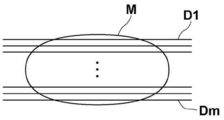
- the image acquisition unit 31 moves the radiation source 16 by rotating the arm portion 12 of the mammography apparatus 10 around the rotation axis 11, and a plurality of radiation sources 16 due to the movement of the radiation source 16.
- the breast M is irradiated with radiation according to a predetermined first imaging condition for tomosynthesis imaging, and the radiation transmitted through the breast M is detected by the radiation detector 15, and a plurality of radiation sources are located at the plurality of radiation source positions.
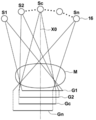
- FIG. 4 is a diagram for explaining the acquisition of the projected image Gi.
- the radiation source 16 is moved to each source position of S1, S2, ..., Sn, and the radiation source 16 is driven at each source position to irradiate the breast M with radiation, and the breast M is irradiated.
- the projected images G1, G2, ..., Gn are acquired corresponding to the respective radiation source positions S1 to Sn.
- the same dose of radiation is applied to the breast M.
- the acquired plurality of projected images Gi are stored in the storage 23.
- the image acquisition unit 31 uses a plurality of tomographic images generated from the plurality of projected images Gi by the reconstruction unit 34 described later as a second breast image. Get as.
- the radiation source position Sc shown in FIG. 4 is a radiation source position where the optical axis X0 of the radiation emitted from the radiation source 16 is orthogonal to the detection surface 15A of the radiation detector 15.
- the radiation source position Sc shall be referred to as a reference radiation source position Sc.
- the image acquisition unit 31 moves the radiation source 16 to the reference source position Sc by rotating the arm portion 12 of the mammography apparatus 10 around the rotation axis 11. Then, the image acquisition unit 31 irradiates the breast M with radiation under a predetermined second imaging condition for simple imaging, detects the radiation transmitted through the breast M with the radiation detector 15, and simplifies the breast M. A two-dimensional image is acquired as a second breast image.
- the image acquisition unit 31 rotates the arm portion 12 of the mammography apparatus 10 around the rotation axis 11 to cause the radiation source 16 as in the case of the simple imaging. Is moved to the reference source position Sc.
- the radiation source 16 may be moved to the radiation source position S1 to perform the first imaging.
- the radiation source 16 includes a filament that outputs an electron beam, a target that generates X-rays when the electron beams collide, and a filter that adjusts the energy spectrum of the X-rays.
- the target has a plurality of different anodic materials such as Mo (molybdenum), Rh (rhodium) and W (tungsten), which are optionally arranged.
- the filter has a number of different substances, such as Mo (molybdenum), Rh (rhodium), W (tungsten) and Al (aluminum), which are optionally arranged.
- the imaging conditions are conditions for adjusting the energy spectrum (radiation quality) of the radiation irradiating the breast M to obtain an appropriate radiation image, for example, the type of target constituting the radiation source 16, the type of filter, and Includes a grid condition that indicates the presence or absence of a scattered radiation removal grid. Further, the radiation generation condition consisting of the tube voltage applied between the filament and the target, and the mAs value (tube current ⁇ irradiation time) are also included in the imaging conditions.
- a table of shooting conditions for each of tomosynthesis shooting and simple shooting is stored in the storage 23.
- the type of target and filter, the tube voltage, the mAs value, and the presence or absence of the grid are set according to the thickness of the breast M.
- the target and filter are set as W / Al (target is W, filter is Al), and no grid is set as the first imaging condition.
- the tube voltage and mAs value are set according to the thickness of the breast M.
- the target and filter are set to W / Rh (target is W, filter is Rh), and the presence of a grid is set as the second shooting condition.
- the tube voltage and mAs value are set according to the thickness of the breast M. Therefore, when simple imaging is performed, as shown in FIG. 2, the scattered radiation removal grid 20 is inserted between the breast M and the radiation detector 15 in the imaging table 13.
- the pre-shooting that is, the shooting conditions at the time of the first shooting are also stored in the storage 23.
- the imaging conditions for the first imaging are the target and the filter, and for the grid, the second imaging condition for simple imaging. Although they are the same, the tube voltage and the mAs value are set to values smaller than those of the second imaging condition.
- the first imaging is performed when the position of the radiation source 16 is at the radiation source position S1
- the imaging conditions of the first imaging are the target and the filter, and the tomosynthesis for the grid. It is the same as the first imaging condition of imaging, but the tube voltage and mAs value are set to be smaller than those of the first imaging condition.
- the imaging conditions of the second imaging are optimized based on the first breast image acquired by the first imaging.
- the optimization method for example, the methods described in JP-A-2007-236804 or JP-A-2017-51752 can be used.
- the method described in JP-A-2007-236804 is based on the first breast image so that the density of the mammary gland region in the radiographic image or tomographic image obtained by the second imaging is appropriate.
- This is a method for optimizing the shooting conditions for shooting.
- the method described in JP-A-2017-51752 determines the presence or absence of an implant in the breast M based on the first breast image, and optimizes the imaging conditions for the second imaging according to the presence or absence of the implant. It is a method to do.
- the three-dimensional information derivation unit 32 acquires the three-dimensional information of the mammary gland included in the first breast image acquired by the first imaging. For this purpose, the three-dimensional information derivation unit 32 first derives the ratio of mammary glands for each pixel in the breast M included in the first breast image, that is, the mammary gland content rate.
- the method described in JP-A-2015-253245 can be used as a method for deriving the mammary gland content.
- the method described in JP-A-2015-253245 creates an adipose image having pixel values when all the mammary gland tissue of the breast is replaced with adipose tissue from the breast image, and the pixel value I (x, y) of the breast image.
- the estimated pixel value A (x, y) of the fat image, the pixel value I0 in the blank region that directly reached the radiation detector 15 without passing through the breast M in the breast image, and the attenuation coefficient of radiation by fat is a method of deriving the mammary gland content G (x, y) for each pixel of the breast image by the following formula (1) based on the value ⁇ representing the ratio with the attenuation coefficient of radiation by the mammary gland.
- the mammary gland content G (x, y) of each pixel in the entire region of the breast M included in the first breast image is derived.
- the three-dimensional information derivation unit 32 multiplies the mammary gland content G (x, y) by the thickness of the breast M, so that the mammary glands of each pixel in the entire region of the breast M included in the first breast image MG1.
- the thickness T (x, y) of is derived.
- the compression thickness of the breast M by the compression plate 17 is used for the thickness of the breast M.
- the thickness of the breast M near the skin line that is not in contact with the compression plate 17 may be derived from the compression thickness by regarding the contour in the cross section of the breast M in the thickness direction as an arc.
- the three-dimensional information derivation unit 32 includes the derived mammary gland thickness T (x, y) in the breast M by multiplying the area of the entire region of the breast M included in the first breast image MG1.
- the volume V0 of the mammary gland is derived as three-dimensional information of the mammary gland.
- the mammary gland volume V0 contained in the breast M may be divided by the breast M volume to derive the ratio R0 of the mammary gland volume as three-dimensional information.
- the volume of the breast M can be derived by multiplying the area of the entire region of the breast M included in the first breast image MG1 by the thickness of the breast M.
- the representative value T0 (hereinafter referred to as the thickness representative value) of the mammary gland thickness T (x, y) may be used as the three-dimensional information.
- the representative thickness value T0 any one of the maximum value, the average value, the median value, and the like of the thickness T (x, y) of the mammary gland can be used.
- the typical thickness value T0 corresponds to the thickness of the mammary gland according to the present disclosure.
- the three-dimensional information of the mammary gland for the entire region of the breast M in the first breast image is derived, but the present invention is not limited to this.
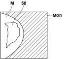
- the region where the mammary gland content G (x, y) is equal to or higher than a predetermined value (for example, 10%) is set as the region of interest 50, and the region of interest 50 is set.
- a predetermined value for example, 10%
- the thickness T (x, y) of the mammary gland within, the volume V1 of the mammary gland, the ratio R1 of the volume of the mammary gland, or the representative thickness T1 in the region of interest 50 may be derived as three-dimensional information. ..
- the volume V1 of the mammary gland in the region of interest 50 can be derived by multiplying the area of the region of interest 50 by the thickness T (x, y) of the mammary gland in the region of interest 50.
- the ratio R1 of the mammary gland volume in the region of interest 50 can be derived by dividing the volume V1 of the mammary gland in the region of interest 50 by the volume of the breast M in the region of interest 50.
- the volume of the breast M in the region of interest 50 can be derived by multiplying the area of the breast M in the region of interest 50 in the first breast image MG1 by the thickness of the breast M.
- the mammary gland volume ratio R0 can also be derived using the following formula (2) described in JP-A-2015-253245.
- the method for deriving the three-dimensional information of the mammary gland is not limited to the method described in Japanese Patent Application Laid-Open No. 2015-253245, and any method can be used.
- the method described in "Robust Breast composition Measurement-Volpara", Ralph Highnam et al., IWDM2010, LNCS; 6136: 342-349, 2010. may be used.
- the thickness of the mammary gland is T (x, y)
- the pixel value of each pixel in the breast image is I (x, y)
- Is F the radiation attenuation coefficient of fat is ⁇ f
- the radiation attenuation coefficient of mammary gland is ⁇ d
- the thickness of the mammary gland is derived by the following equation (3).
- the mammary gland thickness T (x, y) was derived in the entire region of the breast M included in the first breast image MG1 by the method described in the above-mentioned document of Highnam et al., And the derived mammary gland thickness T was derived.
- the volume V0 of the mammary gland contained in the breast M can be derived as three-dimensional information of the mammary gland.
- the ratio R0 of the volume of the mammary gland obtained by dividing the volume V0 of the mammary gland contained in the breast M by the volume of the breast M can be derived as three-dimensional information.
- a region in which the thickness of the mammary gland is equal to or larger than a predetermined value may be set as the region of interest, and three-dimensional information may be derived only within the region of interest. ..
- the imaging mode setting unit 33 sets the imaging mode for the second imaging of the breast M based on the three-dimensional information.
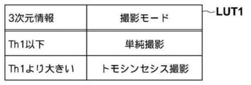
- a table in which the relationship between the three-dimensional information and the shooting mode is associated is stored in the storage 23.
- FIG. 6 is a diagram showing a table in which the relationship between the three-dimensional information and the shooting mode is associated.
- simple shooting is associated with the three-dimensional information below the first threshold value Th1
- the three-dimensional information larger than the first threshold value Th1 is associated with simple shooting.
- Tomosynthesis imaging is associated.
- the volumes V0 and V1 of the mammary gland, the volume ratios R0 and R1 of the mammary gland, and the representative thickness values T0 and T1 are collectively shown as three-dimensional information, but in reality, the three-dimensional information is derived.
- a table is prepared according to the type of three-dimensional information derived by the unit 32. Further, in the table, the first threshold value Th1 is set according to the type of three-dimensional information to be derived. That is, different first threshold values Th1 are set according to the mammary gland volumes V0 and V1, the mammary gland volume ratios R0 and R1, and the thickness representative values T0 and T1.
- the imaging mode setting unit 33 may set the imaging mode using the thickness of the breast M in addition to the three-dimensional information.
- the storage 23 may store a table in which the relationship between the three-dimensional information and the imaging mode according to the thickness of the breast M is associated.
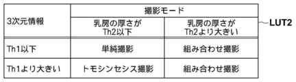
- FIG. 7 is a diagram showing a table in which the relationship between the three-dimensional information and the imaging mode according to the thickness of the breast is associated. Since tomosynthesis imaging is performed by irradiating the breast M with radiation from each of a plurality of radiation source positions, the angle of incidence of the radiation on the radiation detector 15 is different at each imaging position. Therefore, when imaging is performed using the grid, depending on the position of the radiation source, radiation may be blocked by the grid, and the amount of radiation reaching the radiation detector 15 may be reduced. Therefore, the grid is not used when performing tomosynthesis imaging.
- the noise of the projected image and the tomographic image will increase due to the influence of scattered rays, and the image quality will deteriorate.
- the degree of radiation scattering increases, and noise caused by scattered rays increases.
- the table LUT2 is associated with simple imaging when the thickness of the breast M is the threshold Th2 or less with respect to the three-dimensional information of the first threshold Th1 or less.
- the threshold value Th2 When the threshold value Th2 is exceeded, combined imaging of simple imaging and tomosynthesis imaging is associated.
- tomosynthesis imaging is associated with the three-dimensional information exceeding the first threshold value Th1 when the thickness of the breast is the threshold value Th2 or less, and simple imaging and simple imaging are performed when the threshold value exceeds Th2.
- Combination photography of tomosynthesis photography is associated.
- the first threshold value Th1 for three-dimensional information is used in both FIGS. 6 and 7, different threshold values may be set in each of FIGS. 6 and 7.
- the second threshold value may be set to a different value depending on the type of three-dimensional information.
- the imaging mode setting unit 33 sets the imaging mode for the second imaging with reference to the table LUT1 or the table LUT2 based on the three-dimensional information derived by the three-dimensional information derivation unit 32 and the thickness of the breast M. To do. That is, when only the three-dimensional information is used, the shooting mode setting unit 33 refers to the table LUT1 shown in FIG. 6, and when the three-dimensional information is equal to or less than the first threshold value Th1, the shooting mode is set to simple shooting. If the 3D information is larger than the first threshold value Th1, the shooting mode is set to tomosynthesis shooting.
- the imaging mode setting unit 33 refers to the table LUT2 shown in FIG. 7, and when the three-dimensional information is equal to or less than the first threshold value Th1, the breast M When the thickness of is less than the threshold Th2, the imaging mode is set to simple imaging, and when the thickness of the breast M is larger than the threshold Th2, the imaging mode is set to combined imaging.
- the imaging mode is set to tomosynthesis imaging, and the thickness of the breast M is set.
- the shooting mode is set to combined shooting.
- the set shooting mode is output to the image acquisition unit 31.
- the image acquisition unit 31 takes a second image of the breast M in the set imaging mode and acquires the second breast image.
- the second breast image is a simple two-dimensional image.
- the imaging mode is tomosynthesis imaging
- the second breast image is a tomographic image reconstructed using the projected image Gi acquired by tomosynthesis imaging. The reconstruction will be described later.
- the imaging mode is combination imaging
- the second breast image is a simple two-dimensional image and a tomographic image.
- the display control unit 35 displays the first breast image acquired by the first imaging and the second breast image acquired by the second imaging according to the imaging mode on the display unit 3.
- the display control unit 35 displays the simple two-dimensional image on the display unit 3 when the imaging mode is simple imaging.
- the display control unit 35 displays the tomographic image on the display unit 3 when the photographing mode is tomosynthesis imaging.
- the display control unit 35 displays a simple two-dimensional image and a tomographic image on the display unit 3 when the shooting modes are combined shooting.
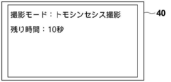
- the notification unit 36 sets at least one of the shooting mode and the remaining time of the second shooting to the display unit 40 and the display unit 3 provided in the mammography apparatus 10. Notify by displaying. In the present embodiment, both the shooting mode and the remaining time of the second shooting are notified.
- FIG. 9 is a diagram showing a notification displayed on the display unit 40. As shown in FIG. 9, the display unit 40 displays “tomosynthesis shooting” as the shooting mode and “10 seconds” as the remaining time. The remaining time is counted down as the shooting progresses, and when the second shooting is completed, the remaining time becomes 0. Further, the same notification is given to the display unit 3. In addition, a bar indicating the remaining time may be displayed instead of a numerical value as the remaining time.
- the shooting mode is simple shooting, at least one of the shooting mode and the remaining time of the second shooting may be notified.
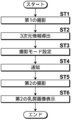
- FIG. 10 is a flowchart showing the processing performed in the present embodiment. It is assumed that the positioning of the breast M on the imaging table 13 has been completed. The process is started when the operator gives an instruction for pre-imaging from the input unit 4, and the image acquisition unit 31 causes the mammography apparatus 10 to perform the first imaging to acquire the first breast image MG1 (step ST1). ). At this time, the shooting switch 5 is pressed by the operator, and the state is maintained until the second shooting is completed unless the positioning is redone.
- the three-dimensional information derivation unit 32 derives the three-dimensional information of the mammary gland included in the first breast image MG1 (step ST2). Then, the imaging mode setting unit 33 sets the imaging mode for the second imaging of the breast M based on the three-dimensional information (step ST3). In addition, the notification unit 36 notifies the set shooting mode and the remaining time of the second shooting (step ST4). Further, the image acquisition unit 31 performs a second image based on the set image capture mode and acquires a second breast image (step ST5). Then, the display control unit 35 displays the second breast image on the display unit 3 (step ST6), and ends the process. The operator can release the shooting switch 5 after confirming that the shooting has been completed by viewing the notification by the notification unit 36.
- the second imaging is performed without moving the radiation source 16. You just have to do.
- the position of the radiation source 16 at the time of the first imaging is the reference radiation source position Sc, and the imaging mode is set to tomosynthesis imaging, the radiation source 16 is moved to the radiation source position S1 and then the second image is taken. You just have to take a picture of. In this case, while the radiation source 16 is moving, the filter and the target may be changed according to the first imaging condition, and the grid 20 may be retracted.
- the imaging mode is set to combination imaging
- simple imaging is performed first, and the radiation source 16 is set to the radiation source position S1.
- the second shooting may be performed.
- the position of the radiation source 16 at the time of the first imaging is the radiation source position S1 and the imaging mode is set to simple imaging
- the second shooting may be performed.
- the filter and the target may be changed and the grid 20 may be inserted according to the second imaging condition. If the position of the radiation source 16 at the time of the first imaging is the radiation source position S1 and the imaging mode is set to tomosynthesis imaging, the second imaging can be performed without moving the radiation source 16. Good.
- the position of the radiation source 16 at the time of the first imaging is the radiation source position S1 and the imaging mode is set to combination imaging, tomosynthesis imaging is performed first, and after the completion of tomosynthesis imaging, the radiation source 16 The second image may be taken after moving to the reference radiation source position Sc.
- the imaging mode for the second imaging of the breast M is set based on the three-dimensional information of the mammary gland included in the first breast image acquired by the first imaging.
- the second breast image is acquired by photographing the breast in the same positioning as the first image by the second image based on the set imaging mode.
- the three-dimensional information of the mammary gland includes not only information on the direction of expansion in the breast image but also information on the direction of thickness of the breast at the time of imaging. Therefore, the three-dimensional information of the mammary gland more appropriately represents the distribution of the mammary gland contained in the breast M. Therefore, according to the present embodiment, the imaging mode of the breast M can be appropriately set.
- the imaging mode can be set more appropriately.
- the burden on the patient is large. For this reason, if it is not known what kind of imaging is currently being performed, the patient will be anxious because it is not possible to know how long the state of pressing the breast M will continue. Further, if the operator releases the shooting switch 5 before the shooting is finished, the shooting is interrupted, so that the operator cannot release the shooting switch 5 during the shooting. However, if the timing at which the shooting ends is not known, it is not possible to know how long the shooting switch 5 should be held down.
- the set shooting mode and the remaining time of the second shooting are notified. Therefore, the patient can know the current imaging mode and the time until the imaging is completed, which can reduce the patient's anxiety. In addition, since the photographer can know the timing when the shooting is finished by the notification, he / she can take his / her hand off the shooting switch 5 with confidence.
- the radiation is not particularly limited, and ⁇ rays, ⁇ rays, etc. can be applied in addition to X-rays.
- the notification unit 36 displays the notification on the display unit 3 and the display unit 40, but the present invention is not limited to this.
- the notification unit 36 may display the notification on the display unit 3 or the display unit 40.
- the display may be changed to or in addition to the display, and a voice notification may be performed.
- a processing unit that executes various processes such as an image acquisition unit 31, a three-dimensional information derivation unit 32, a shooting mode setting unit 33, a reconstruction unit 34, a display control unit 35, and a notification unit 36
- various processors processors shown below can be used.
- the various processors include a CPU, which is a general-purpose processor that executes software (program) and functions as various processing units, and a circuit after manufacturing an FPGA (Field Programmable Gate Array) or the like.
- Dedicated electricity which is a processor with a circuit configuration specially designed to execute specific processing such as programmable logic device (PLD), ASIC (Application Specific Integrated Circuit), which is a processor whose configuration can be changed. Circuits and the like are included.
- One processing unit may be composed of one of these various processors, or a combination of two or more processors of the same type or different types (for example, a combination of a plurality of FPGAs or a combination of a CPU and an FPGA). ) May be configured. Further, a plurality of processing units may be configured by one processor.
- one processor is configured by a combination of one or more CPUs and software, as represented by a computer such as a client and a server. There is a form in which this processor functions as a plurality of processing units.
- SoC System On Chip
- the various processing units are configured by using one or more of the various processors as a hardware structure.
- circuitry in which circuit elements such as semiconductor elements are combined can be used.
Landscapes
- Health & Medical Sciences (AREA)
- Engineering & Computer Science (AREA)
- Life Sciences & Earth Sciences (AREA)
- Medical Informatics (AREA)
- Physics & Mathematics (AREA)
- Radiology & Medical Imaging (AREA)
- General Health & Medical Sciences (AREA)
- Nuclear Medicine, Radiotherapy & Molecular Imaging (AREA)
- Surgery (AREA)
- Public Health (AREA)
- Optics & Photonics (AREA)
- Biomedical Technology (AREA)
- Heart & Thoracic Surgery (AREA)
- Molecular Biology (AREA)
- High Energy & Nuclear Physics (AREA)
- Animal Behavior & Ethology (AREA)
- Biophysics (AREA)
- Pathology (AREA)
- Veterinary Medicine (AREA)
- Human Computer Interaction (AREA)
- General Physics & Mathematics (AREA)
- Theoretical Computer Science (AREA)
- Dentistry (AREA)
- Oral & Maxillofacial Surgery (AREA)
- Quality & Reliability (AREA)
- Computer Vision & Pattern Recognition (AREA)
- Multimedia (AREA)
- Apparatus For Radiation Diagnosis (AREA)
Abstract
Selon la présente invention, une unité d'acquisition d'image acquiert une première image de sein en prenant une image d'un sein par le biais d'une première photographie. Une unité de dérivation d'informations tridimensionnelles dérive des informations tridimensionnelles relatives à une glande mammaire incluse dans la première image de sein. Sur la base des informations tridimensionnelles, une unité de réglage de mode de photographie définit un mode de photographie pour une seconde photographie du sein. Par l'intermédiaire d'une seconde photographie sur la base du mode de photographie ainsi défini, l'unité d'acquisition d'image acquiert une seconde image de sein en prenant une image du sein avec le même positionnement que la première photographie.
Priority Applications (3)
| Application Number | Priority Date | Filing Date | Title |
|---|---|---|---|
| JP2021508713A JP7169430B2 (ja) | 2019-03-27 | 2019-11-12 | 撮影制御装置、方法およびプログラム |
| EP19921770.4A EP3949859B1 (fr) | 2019-03-27 | 2019-11-12 | Dispositif, procédé et programme de commande photographique |
| US17/464,717 US11883221B2 (en) | 2019-03-27 | 2021-09-02 | Imaging control apparatus, imaging control method, and imaging control program |
Applications Claiming Priority (2)
| Application Number | Priority Date | Filing Date | Title |
|---|---|---|---|
| JP2019-060371 | 2019-03-27 | ||
| JP2019060371 | 2019-03-27 |
Related Child Applications (1)
| Application Number | Title | Priority Date | Filing Date |
|---|---|---|---|
| US17/464,717 Continuation US11883221B2 (en) | 2019-03-27 | 2021-09-02 | Imaging control apparatus, imaging control method, and imaging control program |
Publications (1)
| Publication Number | Publication Date |
|---|---|
| WO2020194844A1 true WO2020194844A1 (fr) | 2020-10-01 |
Family
ID=72610891
Family Applications (1)
| Application Number | Title | Priority Date | Filing Date |
|---|---|---|---|
| PCT/JP2019/044391 Ceased WO2020194844A1 (fr) | 2019-03-27 | 2019-11-12 | Dispositif, procédé et programme de commande photographique |
Country Status (4)
| Country | Link |
|---|---|
| US (1) | US11883221B2 (fr) |
| EP (1) | EP3949859B1 (fr) |
| JP (1) | JP7169430B2 (fr) |
| WO (1) | WO2020194844A1 (fr) |
Cited By (3)
| Publication number | Priority date | Publication date | Assignee | Title |
|---|---|---|---|---|
| JP2022148639A (ja) * | 2021-03-24 | 2022-10-06 | 富士フイルム株式会社 | 画像処理装置、放射線画像撮影システム、画像処理方法、及び画像処理プログラム |
| JP2023115845A (ja) * | 2022-02-08 | 2023-08-21 | キヤノンメディカルシステムズ株式会社 | マンモグラフィ装置 |
| US20240206837A1 (en) * | 2022-12-22 | 2024-06-27 | Fujifilm Corporation | Mammography apparatus |
Families Citing this family (1)
| Publication number | Priority date | Publication date | Assignee | Title |
|---|---|---|---|---|
| JP2024128889A (ja) * | 2023-03-10 | 2024-09-24 | 富士フイルム株式会社 | 画像処理装置、画像撮影システム、画像処理方法、画像処理プログラム |
Citations (6)
| Publication number | Priority date | Publication date | Assignee | Title |
|---|---|---|---|---|
| JP2007050264A (ja) | 2005-08-15 | 2007-03-01 | Hologic Inc | 患者胸部のx線マンモグラフィ/トモシンセシス |
| JP2007236804A (ja) | 2006-03-10 | 2007-09-20 | Toshiba Corp | 乳房撮影用x線診断装置及び乳房撮影用x線診断プログラム |
| JP2009072410A (ja) * | 2007-09-21 | 2009-04-09 | Toshiba Corp | 複合画像診断装置 |
| JP2012135444A (ja) | 2010-12-27 | 2012-07-19 | Fujifilm Corp | 撮影制御装置および撮影制御方法 |
| US20140133626A1 (en) * | 2012-11-09 | 2014-05-15 | Samsung Electronics Co., Ltd. | X-ray imaging apparatus and x-ray imaging method |
| JP2017051752A (ja) | 2016-12-20 | 2017-03-16 | 富士フイルム株式会社 | 放射線画像撮影装置および方法 |
Family Cites Families (18)
| Publication number | Priority date | Publication date | Assignee | Title |
|---|---|---|---|---|
| US7123684B2 (en) * | 2002-11-27 | 2006-10-17 | Hologic, Inc. | Full field mammography with tissue exposure control, tomosynthesis, and dynamic field of view processing |
| US10638994B2 (en) * | 2002-11-27 | 2020-05-05 | Hologic, Inc. | X-ray mammography with tomosynthesis |
| DE102006051778A1 (de) | 2006-11-02 | 2008-05-15 | Siemens Ag | Verfahren und Einrichtung zur Anzeige eines im Rahmen einer Mammographie aufgenommenen Röntgenbildes |
| JP5052123B2 (ja) * | 2006-12-27 | 2012-10-17 | 富士フイルム株式会社 | 医用撮像システム及び方法 |
| JP5481038B2 (ja) * | 2007-04-05 | 2014-04-23 | 株式会社東芝 | 超音波診断装置、乳房イメージングシステム及び乳房イメージングプログラム |
| DE102010035920A1 (de) * | 2010-08-31 | 2012-03-01 | Siemens Aktiengesellschaft | Verfahren zur Darstellung eines vorbestimmten Volumenabschnitts eines Untersuchungsobjekts mittels eines Tomosynthesegeräts und entsprechendes Tomosynthesegerät |
| US9168013B2 (en) * | 2010-12-13 | 2015-10-27 | Koninklijke Philips N.V. | Breast density assessment |
| JP5844296B2 (ja) * | 2012-06-11 | 2016-01-13 | 富士フイルム株式会社 | 放射線画像処理装置および方法 |
| JP2014061232A (ja) | 2012-09-24 | 2014-04-10 | Toshiba Corp | 乳房x線撮影装置 |
| WO2014195669A1 (fr) * | 2013-06-06 | 2014-12-11 | Matakina Technology Ltd | Procédé de reconstruction d'un objet à partir de vues en projection |
| KR102264462B1 (ko) * | 2013-10-09 | 2021-06-15 | 홀로직, 인크. | 편평화된 유방의 두께 방향을 포함하는 공간 해상도를 향상시키는 x선 유방 영상합성 |
| JP2017047103A (ja) | 2015-09-04 | 2017-03-09 | キヤノン株式会社 | 制御装置、乳房撮影システム、乳房撮影装置の制御方法 |
| JP6656199B2 (ja) | 2017-03-30 | 2020-03-04 | 富士フイルム株式会社 | マンモグラフィ装置 |
| JP7022543B2 (ja) * | 2017-09-11 | 2022-02-18 | キヤノン株式会社 | 乳房撮影装置、乳房撮影装置の制御方法及びプログラム |
| WO2019227051A2 (fr) * | 2018-05-25 | 2019-11-28 | Hologic, Inc. | Systèmes et procédés de pivotement de palpateurs de compression |
| JP7053102B2 (ja) * | 2018-09-27 | 2022-04-12 | 富士フイルム株式会社 | 情報処理装置とその作動プログラムおよび作動方法、並びに乳房撮影装置 |
| US12059280B2 (en) * | 2020-02-25 | 2024-08-13 | GE Precision Healthcare LLC | Methods and systems for dynamic collimation |
| KR102447341B1 (ko) * | 2020-04-10 | 2022-09-26 | 주식회사 뷰웍스 | 유방 촬영 장치 및 방법 |
-
2019
- 2019-11-12 JP JP2021508713A patent/JP7169430B2/ja active Active
- 2019-11-12 EP EP19921770.4A patent/EP3949859B1/fr active Active
- 2019-11-12 WO PCT/JP2019/044391 patent/WO2020194844A1/fr not_active Ceased
-
2021
- 2021-09-02 US US17/464,717 patent/US11883221B2/en active Active
Patent Citations (6)
| Publication number | Priority date | Publication date | Assignee | Title |
|---|---|---|---|---|
| JP2007050264A (ja) | 2005-08-15 | 2007-03-01 | Hologic Inc | 患者胸部のx線マンモグラフィ/トモシンセシス |
| JP2007236804A (ja) | 2006-03-10 | 2007-09-20 | Toshiba Corp | 乳房撮影用x線診断装置及び乳房撮影用x線診断プログラム |
| JP2009072410A (ja) * | 2007-09-21 | 2009-04-09 | Toshiba Corp | 複合画像診断装置 |
| JP2012135444A (ja) | 2010-12-27 | 2012-07-19 | Fujifilm Corp | 撮影制御装置および撮影制御方法 |
| US20140133626A1 (en) * | 2012-11-09 | 2014-05-15 | Samsung Electronics Co., Ltd. | X-ray imaging apparatus and x-ray imaging method |
| JP2017051752A (ja) | 2016-12-20 | 2017-03-16 | 富士フイルム株式会社 | 放射線画像撮影装置および方法 |
Non-Patent Citations (2)
| Title |
|---|
| RALPH HIGHNAM ET AL.: "Robust Breast composition Measurement-Volpara", IWDM2010, LNCS, vol. 6136, 2010, pages 342 - 349, XP002604953 |
| See also references of EP3949859A4 |
Cited By (5)
| Publication number | Priority date | Publication date | Assignee | Title |
|---|---|---|---|---|
| JP2022148639A (ja) * | 2021-03-24 | 2022-10-06 | 富士フイルム株式会社 | 画像処理装置、放射線画像撮影システム、画像処理方法、及び画像処理プログラム |
| US12133756B2 (en) | 2021-03-24 | 2024-11-05 | Fujifilm Corporation | Image processing device, radiography system, image processing method, and image processing program |
| JP7607485B2 (ja) | 2021-03-24 | 2024-12-27 | 富士フイルム株式会社 | 画像処理装置、放射線画像撮影システム、画像処理方法、及び画像処理プログラム |
| JP2023115845A (ja) * | 2022-02-08 | 2023-08-21 | キヤノンメディカルシステムズ株式会社 | マンモグラフィ装置 |
| US20240206837A1 (en) * | 2022-12-22 | 2024-06-27 | Fujifilm Corporation | Mammography apparatus |
Also Published As
| Publication number | Publication date |
|---|---|
| JP7169430B2 (ja) | 2022-11-10 |
| EP3949859B1 (fr) | 2025-03-26 |
| JPWO2020194844A1 (fr) | 2020-10-01 |
| US20210393225A1 (en) | 2021-12-23 |
| US11883221B2 (en) | 2024-01-30 |
| EP3949859A1 (fr) | 2022-02-09 |
| EP3949859A4 (fr) | 2022-05-18 |
Similar Documents
| Publication | Publication Date | Title |
|---|---|---|
| JP7122886B2 (ja) | 撮影制御装置、方法およびプログラム | |
| JP6682150B2 (ja) | 乳腺量取得装置、方法およびプログラム | |
| US11883221B2 (en) | Imaging control apparatus, imaging control method, and imaging control program | |
| JP2017143943A (ja) | 放射線画像処理装置、方法およびプログラム | |
| JP7203705B2 (ja) | 画像処理装置、方法およびプログラム、並びに画像表示装置、方法およびプログラム | |
| JP7326070B2 (ja) | 画像表示装置、方法およびプログラム、画像管理装置、方法およびプログラム | |
| JP5669799B2 (ja) | 画像処理装置、放射線画像撮影システム、画像処理プログラム、及び画像処理方法 | |
| JP7384990B2 (ja) | 画像管理装置、方法およびプログラム | |
| US11484275B2 (en) | Image processing apparatus, method, and program | |
| JP7209599B2 (ja) | 画像処理装置、方法およびプログラム | |
| JP7270781B2 (ja) | 画像設定装置、画像設定装置の作動方法および画像設定プログラム | |
| US12327352B2 (en) | Image setting device, image setting method, and image setting program | |
| US11779297B2 (en) | Control device, control method, and control program | |
| JP7208874B2 (ja) | 撮影制御装置、方法およびプログラム | |
| US12597126B2 (en) | Image setting device, image setting method, and image setting program | |
| US11779299B2 (en) | Control device, control method, and control program | |
| JP2025040874A (ja) | 画像処理装置、放射線画像撮影システム及びプログラム | |
| JP2013046708A (ja) | 乳房x線撮影装置、画像処理装置、及び画像処理方法 |
Legal Events
| Date | Code | Title | Description |
|---|---|---|---|
| 121 | Ep: the epo has been informed by wipo that ep was designated in this application |
Ref document number: 19921770 Country of ref document: EP Kind code of ref document: A1 |
|
| ENP | Entry into the national phase |
Ref document number: 2021508713 Country of ref document: JP Kind code of ref document: A |
|
| NENP | Non-entry into the national phase |
Ref country code: DE |
|
| ENP | Entry into the national phase |
Ref document number: 2019921770 Country of ref document: EP Effective date: 20211027 |