WO2020194858A1 - Dispositif de planification de traitement, procédé de planification de traitement, et programme - Google Patents
Dispositif de planification de traitement, procédé de planification de traitement, et programme Download PDFInfo
- Publication number
- WO2020194858A1 WO2020194858A1 PCT/JP2019/045904 JP2019045904W WO2020194858A1 WO 2020194858 A1 WO2020194858 A1 WO 2020194858A1 JP 2019045904 W JP2019045904 W JP 2019045904W WO 2020194858 A1 WO2020194858 A1 WO 2020194858A1
- Authority
- WO
- WIPO (PCT)
- Prior art keywords
- calculation
- dose
- interest
- irradiation
- dose distribution
- Prior art date
- Legal status (The legal status is an assumption and is not a legal conclusion. Google has not performed a legal analysis and makes no representation as to the accuracy of the status listed.)
- Ceased
Links
Images






Classifications
-
- A—HUMAN NECESSITIES
- A61—MEDICAL OR VETERINARY SCIENCE; HYGIENE
- A61N—ELECTROTHERAPY; MAGNETOTHERAPY; RADIATION THERAPY; ULTRASOUND THERAPY
- A61N5/00—Radiation therapy
- A61N5/10—X-ray therapy; Gamma-ray therapy; Particle-irradiation therapy
Definitions
- the spot scanning method which uses a fine particle beam to irradiate the target so as to fill it, is becoming the mainstream irradiation method.
- the optimization calculation determines what kind of irradiation amount should be applied to which spot from which angle to form the desired dose distribution. This process is called a treatment plan.
- the treatment plan includes the process of inputting the contour of the organ as a ROI (Region of Interest).
- ROI Region of Interest
- different organs have different sensitivities to radiation, for example, when exposed to the same amount of radiation, organs with mucosa (such as the intestine) are more damaged than bone. Organs that are easily damaged by radiation are called dangerous organs (OAR: Organ at Risk).
- OAR Organ at Risk
- the index for evaluating the dose distribution created by the treatment plan differs for each organ and is specified by the doctor. For example, a condition such as "the volume at which organ A is irradiated with X% or more of the prescribed dose must not exceed Y%" is used in the optimization calculation.
- the treatment planning device includes a display device for displaying tomographic image information including the affected area and a dose of particle beams irradiated to at least one region of interest set in the affected area. It has an input device that accepts input of calculation designation information that specifies the necessity of calculation of the distribution, and an arithmetic device that calculates the dose distribution of the region of interest for which the calculation of the dose distribution is designated based on the calculation designation information.
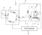
- FIG. 1 It is a schematic block diagram which shows the particle beam therapy system which concerns on Example 1.
- FIG. It is a schematic block diagram which shows the particle beam therapy apparatus which concerns on Example 1.
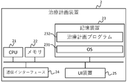
- FIG. It is a block diagram which shows the treatment planning apparatus of Example 1.
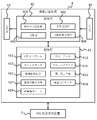
- FIG. It is a block diagram which shows the function of the dose calculation apparatus of Example 1.
- FIG. It is a flowchart which shows the operation before irradiation of the particle beam therapy system which concerns on Example 1.
- FIG. It is a flowchart which shows the treatment plan making process by the irradiation plan making apparatus of Example 1.
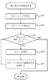
- It is a flowchart which shows the interest area classification designation processing by the dose calculation apparatus of Example 1.
- FIG. 1 is a schematic configuration diagram showing a particle beam therapy system according to Example 1 to which the treatment planning apparatus according to Example 1 is applied.
- the particle beam therapy system S of this embodiment has a particle beam therapy device 1 and a treatment planning device 2.
- the particle beam therapy system S of this embodiment employs a spot scanning method.
- the particle beam therapy device 1 irradiates the affected area with particle beams to treat the affected area.
- the treatment planning device 2 has an irradiation planning device 3 and a dose calculation device 4.
- the dose calculation device 4 accepts input of irradiation log data including data on the irradiation position and irradiation amount when the affected area is actually irradiated from the particle beam therapy device 1. Further, the dose calculation device 4 accepts the input of kernel data from the irradiation plan creation device 3. Then, the dose calculation device 4 calculates the effective dose and the index by using the fluence map and the kernel data obtained from the irradiation log data based on the classification of ROI.
- the irradiation plan creation device 3 reoptimizes (replans, corrects) the irradiation parameters of the particle beam in the remaining irradiation plans based on the effective dose calculated by the dose calculation device 4.
- the treatment plan program 232 described later is executed on the treatment plan device 2 in these irradiation plan creation devices 3 and the like. As a result, it is virtually configured in one treatment planning device 2.
- FIG. 2 is a schematic configuration diagram showing a particle beam therapy apparatus according to the first embodiment.
- the particle beam therapy device 1 of this embodiment includes an accelerator, a beam transport system 13, an irradiation nozzle 14, a treatment table 15, and an irradiation control device 16.
- FIG. 2 shows an example of the injector 11 and the synchrotron accelerator 12 as accelerators, a cyclotron accelerator may also be used.
- the beam transport system 13 has a rotating gantry, but may be a fixed irradiation port.
- the particle beam generated and accelerated by the injector 11 enters the synchrotron accelerator 12, is further accelerated by the synchrotron accelerator 12, and is emitted to the beam transport system 13.
- the beam transport system 13 includes a plurality of deflection electromagnets 13a and a quadrupole electromagnet (not shown), and is connected to the synchrotron accelerator 12 and the irradiation nozzle 14. Further, a part of the beam transport system 13 and the irradiation nozzle 14 are installed in the rotating gantry, and can rotate together with the gantry. The particle beam emitted from the synchrotron accelerator 12 is converged by the quadrupole electromagnet while passing through the beam transport system 13, and is changed in the direction by the deflection electromagnet 13a to enter the irradiation nozzle 14.
- the irradiation nozzle 14 has a scanning electromagnet, a dose monitor, and a beam position monitor (none of which are shown).
- the scanning electromagnet deflects the proton beam so that it reaches the desired position in the plane perpendicular to the beam axis at the target position.
- the dose monitor is a monitor that measures the amount of particle beam irradiation applied to the target.
- the beam position monitor is a monitor for indirectly measuring the irradiation position of the proton beam irradiated to the target by detecting the position where the particle beam irradiated to the target has passed.
- the particle beam that has passed through the irradiation nozzle 14 reaches a target in the irradiation target (not shown) on the treatment table 15.
- the irradiation target represents the patient and the target represents the affected area or the like.
- the treatment table 15 on which the irradiation target is placed can move in the directions of three orthogonal axes based on the instruction from the irradiation control device 16, and can further rotate around each axis. By these movements and rotations, the position of the irradiation target can be moved to a desired position.
- the storage device 23 is composed of, for example, a flash memory device, a hard disk drive (HDD), or the like, and stores computer programs such as an operating system 231 and a treatment planning program 232. In addition to these computer programs 231 and 232, software (not shown) such as driver software is also stored in the storage device 23.
- software such as driver software is also stored in the storage device 23.
- the input unit 42 includes an information input device of the user interface device 25, etc., receives various data for the dose calculation device 4, and sends the accepted data to the control unit 40 and the storage unit 41.
- the data received by the input unit 42 there are calculation designation information, reference value designation information, and the like.
- the irradiation plan creation device 3 of the treatment planning device 2 creates a treatment plan (step S1). The details of the treatment planning process will be described later.
- the irradiation plan creation device 3 transmits the treatment plan created in step S1 to the particle beam therapy device 1 (step S2), and the particle beam therapy device 1 receives the treatment plan (step S3).
- the irradiation plan creation device 3 stores the kernel data 413 based on the treatment plan created in step S1 in the storage device 23 (step S4).
- the kernel data 413 is data used when calculating the expected dose distribution in the patient's body including the affected area.
- step S23 it is determined whether or not there is an area of interest for which the dose distribution is to be confirmed (step S23), and when it is determined that there is an area of interest for which the dose distribution is to be confirmed (YES in step S23), the input unit 42 Accepts a designated input of an area of interest from a doctor or the like (step S24).
- step S24 the input unit 42 receives the designated input of the classification and the reference value of the dose condition (index) from the doctor or the like for the region of interest for which the designated input was received in step S24 (step S25).
- the display unit 43 displays two check boxes 54 and 55 for inputting the classification designation of the region of interest.
- the check box 54 is a check box 54 in which the input unit 42 accepts a designated input for monitoring the effective dose for the region of interest selected by operating the pull-down menu 53.
- the other check box 55 is a check box 55 in which the input unit 42 accepts the designated input of the dose condition for the region of interest selected by operating the pull-down menu 53.
- the input unit 42 When the input unit 42 accepts the operation input of the registration button 58 displayed by the display unit 43 in FIG. 8, it accepts the classification and reference value of the region of interest that is accepting the input at that time.
- the control unit 40 stores the information received by the input unit 42 in the storage unit 41 as calculation designation information 416 and reference value designation information 417. After that, the control unit 40 returns to step S23 and continues the operation.
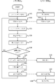
- FIG. 9 is a flowchart showing the dose distribution calculation operation of the particle beam therapy system S according to the first embodiment.
- the irradiation plan creation device 3 of the treatment planning device 2 reads out the kernel data 413 saved in the storage device 23 in step S18 of FIG. 6 and sends it to the dose calculation device 4.
- the dose calculation device 4 reads the kernel data 413 sent from the irradiation plan creation device 3 (step S31).
- the particle beam therapy device 1 irradiates the patient with particle beams (step S32). Then, when the particle beam therapy device 1 irradiates the patient with a constant dose (for example, every 0.5 Gy), the particle beam therapy device 1 transmits irradiation log data 411 to the treatment planning device 2 (step S33).
- the irradiation log data 411 includes the irradiation amount measured by the dose monitor and the irradiation position measured by the beam position monitor.
- the dose calculation device 4 of the treatment planning device 2 waits for the irradiation log data 411 to be transmitted from the particle beam therapy device 1, and receives the irradiation log data 411 when the particle beam therapy device 1 transmits the irradiation log data 411. (Step S34).
- the dose distribution calculation unit 401 of the dose calculation device 4 generates a fluence map 414 based on the irradiation log data 411 received in step S32 (step S35). Further, the dose distribution calculation unit 401 calculates the effective dose for the regions of interest classified into the categories (1) and (2) based on the fluence map 414 generated in step S35 (step S36).
- the display control unit 402 generates a display control signal for displaying the screen showing the effective dose calculated in step S36 on the display surface of the display unit 43, and sends it to the display unit 43.
- the display unit 43 displays a screen showing the effective dose on the display surface based on the display control signal (step S37).
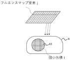
- the particle beam irradiated to the patient forms a virtual fluence map (fluence map) 414.
- the fluence map 414 has elements j arranged in a matrix. Each fluence map element j has a value corresponding to the irradiation amount of the particle beam actually irradiated to the patient from the plane position of each element j of the fluence map 414, which is calculated based on the irradiation log data 411.
- FIG. 11 is a diagram for explaining the principle of dose distribution calculation by the dose calculation device 4 of the first embodiment, and is a diagram showing kernel data 413 read in step S31.
- the kernel data 413 shows which of the minute volumes i of the region of interest 61 of the patient 6 when the particle beam is irradiated into the patient body from each element j of the fluence map 414. It is a set of values calculated for each element of the fluence map 414 as a value (ratio) indicating how to be absorbed. In other words, the kernel data 413 determines the dose distribution formed in each of the minute volumes i of the region of interest 61 when a unit dose (ie, the dose is 1) is incident on each element j of the fluence map 414. It is a collection.
- Each element of the kernel data 413 shows the effect of each element j of the fluence map 414 on the minute volume i of the region of interest 61, that is, the dose contribution.
- Row 414a of the fluence map 414 shows the effect of the minute volume i from each element j of the fluence map 414.
- Column 414b of the fluence map 414 shows the dose distribution formed by each element j of the fluence map 414 over all of the minute volumes i.
- FIG. 12 is a diagram for explaining the principle of dose distribution calculation by the dose calculation device 4 of the first embodiment, and is a diagram showing an equation for calculating the effective dose by the dose distribution calculation unit 401.
- the comparison unit 403 compares the effective dose calculated in step S36 with the set reference value for the region of interest classified in the classification (1), and determines whether the effective dose satisfies the dose condition. (Step S38). To determine whether the effective dose satisfies the dose condition, the comparison unit 403 determines that the dose condition is satisfied if the effective dose is approximately equal to the reference value, and the comparison unit 403 determines whether the effective dose exceeds or falls below the reference value. Determines that the dose condition is not met.
- step S38 the comparison unit 403 determines that the effective dose satisfies the dose condition (YES in step S38)
- the process returns to step S34, and the dose calculation device 4 transmits the irradiation log data 411 from the particle beam therapy device 1. Wait.
- the display control unit 402 displays a warning display screen notifying that the effective dose does not satisfy the dose condition.
- a display control signal for displaying on the display surface of is generated, and this display control signal is transmitted to the display unit 43.
- the display unit 43 displays a warning display screen based on the display control signal transmitted from the display control unit 402 (step S39).
- the comparison result sending unit 404 sends an irradiation stop instruction signal instructing the stop of the particle beam irradiation by the particle beam therapy device 1 to the particle beam therapy device 1 (step S39).
- the particle beam therapy device 1 stops the particle beam irradiation to the patient based on the irradiation stop instruction signal sent from the comparison result sending unit 404 (step S40).
- the comparison result sending unit 404 sends the comparison result of the comparison unit 403 to the irradiation plan creating device 3.
- the irradiation plan creation device 3 recreates the treatment plan based on the comparison result (step S41), and transmits the recreated treatment plan to the particle beam therapy device 1 (step S42).
- the particle beam therapy device 1 receives the treatment plan transmitted from the irradiation plan creation device 3 (step S43), and irradiates the particle beam based on this treatment plan (step S44).
- the display unit 43 displays the X-ray CT image 415 including the affected area
- the input unit 42 calculates the dose distribution for at least one region of interest set in the affected area.
- the control unit 40 especially the dose distribution calculation unit 401, calculates the dose distribution of the region of interest for which the calculation of the dose distribution is designated based on the calculation designation information 416. There is.
- Anatomical changes include weight gain and loss, tumor shrinkage, stuffy nose or tissue swelling. It is conceivable that the change causes the beam range in the body to change (that is, the position where the beam stops changes). By creating kernel data 413 in consideration of daily changes in the patient's body, safer treatment can be provided.
- the flowchart of FIG. 5 is performed using the X-ray CT image to create kernel data 413.
- the organ name or identification number for the region of interest ROI data 412 including a contour image of the region of interest
- calculation designation information 416 calculation designation information 416
- a reference value a reference value for the designated information 417 is automatically transferred to a new X-ray CT image.
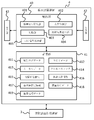
- FIG. 13 is a configuration diagram showing the function of the dose calculation device 4 of the third embodiment.
- the same components as those in the first embodiment are designated by the same reference numerals, and the description thereof will be simplified.
- a moving body tracking irradiation technique was developed to accurately irradiate a tumor whose position changes due to respiration near the trunk, especially the lungs (for example, Patent No. 5976474).
- fluoroscopic images near the tumor are taken at a constant frequency (for example, 30 times per second).
- a gate signal indicating that irradiation is possible is transmitted to the irradiation device.
- the beam is irradiated while the gate signal, which means that the irradiation device can irradiate, rises.
- the tumor position analysis includes a method of analyzing the movement of a marker artificially inserted near the tumor and a method of analyzing the position using only image data of the patient's organ.
- the moving body tracking irradiation technology has made it possible to irradiate moving organs with high precision.
- the beam cannot be irradiated, which may increase the treatment time.
- the width of the gate signal is wide (that is, if the rising time is long)
- the irradiation time is increased and the treatment time is shortened.
- the organs are moved within the irradiation time, the irradiation accuracy is lowered.
- accuracy and time are in a trade-off relationship.
- the dose calculation device 4 of the present embodiment shown in FIG. 13 differs only in that it has a control signal transmission unit 405 in addition to the dose calculation device 4 of the above-described first embodiment, and the other components are the configurations of the first embodiment. Same as the element.
- the control signal transmission unit 405 transmits a control signal for controlling the irradiation range of the particle beam irradiated to the region of interest based on the comparison result of the comparison unit 403.
- the control signal referred to here is, for example, a gate signal transmitted to the particle beam therapy device 1.
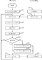
- FIG. 14 is a flowchart showing the dose distribution calculation operation of the particle beam therapy system S according to the third embodiment.
- steps S51 to S57 are the same as steps S30 to S37 of the flowchart of the first embodiment shown in FIG.
- the comparison unit 403 compares the effective dose T with the dose index C (step S58). As a result, when the comparison unit 403 determines that the effective dose T is smaller than the dose index C (T ⁇ C in step S58), the control signal transmission unit 405 is the gate signal currently transmitted to the particle beam therapy device 1. Control to widen the width is performed (step S59). Further, when the comparison unit 403 determines that the effective dose T is larger than the dose index C (T> C in step S58), the control signal transmission unit 405 has the width of the gate signal currently transmitted to the particle beam therapy device 1. Is controlled to be narrowed (step S60).
- the process returns to step S54, and the dose calculation device 4 receives the irradiation log data 411 from the particle beam therapy device 1. Wait for to be sent.
- control signal transmission unit 405 transmits the changed gate signal to the particle beam therapy device 1 after controlling the gate signal to be widened or narrowed (step S61).
- the particle beam therapy device 1 changes the gate signal used for particle beam irradiation based on the gate signal received from the dose calculation device 4 (step S62).
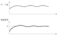
- FIG. 15 is a diagram illustrating an operation of gate width control by the dose calculation device 4 of the third embodiment.
- the control signal transmission unit 405 feeds back the width of the gate signal according to the achievement level of the index, and after a certain period of time, the most efficient gate width for the patient being treated. It is possible to perform control to stabilize with.
- the dose distribution calculation unit 401 calculates the effective dose, the width of the gate signal can be adjusted while confirming the accuracy of the effective dose with respect to the dose index.
- the accuracy of irradiation and the irradiation time can be optimized.
- the particle beam therapy device 1 transmits the relationship between the tumor position and the time monitored by the moving body tracking to the dose calculation device 4, and the particle beam therapy device 1 further adds the irradiation amount and the irradiation position.
- the time information can be transmitted to the dose calculation device 4. This makes it possible for the dose calculation device 4 to reflect the amount of movement of the tumor in the irradiation position and create a fluence map 414 in consideration of body movement.
- the present invention is not limited to the above-mentioned examples, and includes various modifications.
- the above-described embodiment has been described in detail in order to explain the present invention in an easy-to-understand manner, and is not necessarily limited to those having all the described configurations.
- it is possible to replace a part of the configuration of one embodiment with the configuration of another embodiment and it is also possible to add the configuration of another embodiment to the configuration of one embodiment.
- the irradiation plan creation device 3 and the dose calculation device 4 have been described as being realized by the same hardware, but these may be realized by different hardware.
- Examples 1 to 3 an example in which the effective dose is calculated for each fixed dose is shown (for example, the effective dose is calculated and displayed every time 0.5 Gy is irradiated).
- the dose to be irradiated does not have to be kept constant at all times.
- the widow or widower treatment for example, when it is necessary to irradiate a patient with 10 Gy, first irradiate 0.5 Gy and then pause. The effective dose is then calculated and the dose distribution or indicators that can be calculated from the dose distribution are compared with the indicators in the treatment plan. If the index in the treatment plan is achieved, the next dose may be increased to 1 Gy and then paused to calculate the effective dose. It is also conceivable to implement a function that automatically repeats this process until the dose required for treatment and 10 Gy are all irradiated.
- each of the above configurations, functions, processing units, processing means, etc. may be realized by hardware by designing a part or all of them by, for example, an integrated circuit. Further, each of the above configurations, functions, and the like may be realized by software by the processor interpreting and executing a program that realizes each function. Information such as programs, tables, and files that realize each function can be placed in a memory, a recording device such as a hard disk or SSD, or a recording medium such as an IC card, SD card, or DVD.
- control lines and information lines indicate what is considered necessary for explanation, and not all control lines and information lines are necessarily shown on the product. In practice, it can be considered that almost all configurations are interconnected.
Landscapes
- Health & Medical Sciences (AREA)
- Engineering & Computer Science (AREA)
- Biomedical Technology (AREA)
- Pathology (AREA)
- Nuclear Medicine, Radiotherapy & Molecular Imaging (AREA)
- Radiology & Medical Imaging (AREA)
- Life Sciences & Earth Sciences (AREA)
- Animal Behavior & Ethology (AREA)
- General Health & Medical Sciences (AREA)
- Public Health (AREA)
- Veterinary Medicine (AREA)
- Radiation-Therapy Devices (AREA)
Abstract
La présente invention permet d'effectuer rapidement un calcul de dose efficace. Un dispositif de planification de traitement (2) comprend : un dispositif d'affichage (43) qui affiche des informations d'image tomographique comportant une partie affectée ; un dispositif d'entrée (42) qui accepte en entrée des informations de désignation de calcul indiquant s'il est nécessaire de calculer une administration de dose d'un faisceau de particules projeté sur au moins une région d'intérêt qui a été définie pour la partie affectée ; et un dispositif de calcul (40) qui calcule, sur la base des informations de désignation de calcul, l'administration de dose à une région d'intérêt pour laquelle un calcul d'administration de dose a été désigné.
Applications Claiming Priority (2)
| Application Number | Priority Date | Filing Date | Title |
|---|---|---|---|
| JP2019064207A JP7281131B2 (ja) | 2019-03-28 | 2019-03-28 | 治療計画装置、治療計画方法及びプログラム |
| JP2019-064207 | 2019-03-28 |
Publications (1)
| Publication Number | Publication Date |
|---|---|
| WO2020194858A1 true WO2020194858A1 (fr) | 2020-10-01 |
Family
ID=72608888
Family Applications (1)
| Application Number | Title | Priority Date | Filing Date |
|---|---|---|---|
| PCT/JP2019/045904 Ceased WO2020194858A1 (fr) | 2019-03-28 | 2019-11-25 | Dispositif de planification de traitement, procédé de planification de traitement, et programme |
Country Status (2)
| Country | Link |
|---|---|
| JP (1) | JP7281131B2 (fr) |
| WO (1) | WO2020194858A1 (fr) |
Families Citing this family (1)
| Publication number | Priority date | Publication date | Assignee | Title |
|---|---|---|---|---|
| CN117083107A (zh) * | 2021-01-26 | 2023-11-17 | 阿朵思有限责任公司 | 用于放射疗法系统的剂量引导和最终递送辐射剂量的重复估计的系统和方法 |
Citations (2)
| Publication number | Priority date | Publication date | Assignee | Title |
|---|---|---|---|---|
| JP2002336365A (ja) * | 2001-05-17 | 2002-11-26 | Mitsubishi Electric Corp | 線量シミュレーション計算方法 |
| JP2017184929A (ja) * | 2016-04-04 | 2017-10-12 | 株式会社日立製作所 | 放射線治療計画装置 |
-
2019
- 2019-03-28 JP JP2019064207A patent/JP7281131B2/ja active Active
- 2019-11-25 WO PCT/JP2019/045904 patent/WO2020194858A1/fr not_active Ceased
Patent Citations (2)
| Publication number | Priority date | Publication date | Assignee | Title |
|---|---|---|---|---|
| JP2002336365A (ja) * | 2001-05-17 | 2002-11-26 | Mitsubishi Electric Corp | 線量シミュレーション計算方法 |
| JP2017184929A (ja) * | 2016-04-04 | 2017-10-12 | 株式会社日立製作所 | 放射線治療計画装置 |
Also Published As
| Publication number | Publication date |
|---|---|
| JP2020162701A (ja) | 2020-10-08 |
| JP7281131B2 (ja) | 2023-05-25 |
Similar Documents
| Publication | Publication Date | Title |
|---|---|---|
| JP6896164B2 (ja) | 放射線治療計画最適化ワークフロー | |
| JP7245352B2 (ja) | 粒子を用いた回転式の放射線治療を提供する方法 | |
| JP6974232B2 (ja) | 粒子線治療計画装置、粒子線治療システムおよび線量分布演算プログラム | |
| JP6375097B2 (ja) | 放射線治療計画装置及び治療計画方法 | |
| RU2603606C2 (ru) | Изучение дозиметрического воздействия движения на формирование адаптивных границ для конкретного пациента при планировании наружной дистанционной лучевой терапии | |
| JP6377762B2 (ja) | 画像誘導放射線治療 | |
| JP5909167B2 (ja) | 放射線治療計画装置 | |
| KR20170047215A (ko) | 방사선 역 치료 계획을 위한 시스템 및 컴퓨터 프로그램 제품 | |
| JP2019136509A (ja) | オーバーラップする輪郭への放射線量の最適化 | |
| US11969608B2 (en) | System and method for passive ion radiotherapy treatment planning and delivery | |
| JP2018515274A (ja) | ビームジオメトリを選択する方法 | |
| US11426603B2 (en) | Radiation irradiation planning apparatus, clinical decision support apparatus and program | |
| US9364686B2 (en) | Planning a treatment beam aimed at one or more target regions | |
| JP7616867B2 (ja) | 放射線治療装置及び方法 | |
| WO2020137234A1 (fr) | Système de thérapie par particules, système d'évaluation de distribution de dose et procédé de fonctionnement d'un système de thérapie par particules | |
| JP7281131B2 (ja) | 治療計画装置、治療計画方法及びプログラム | |
| JP7408078B2 (ja) | 患者体内構造変化検出方法、患者体内構造変化検出装置およびコンピュータプログラム | |
| JP2022111774A (ja) | 判断支援システム、放射線治療システム及び判断支援システムにおける判断支援方法 | |
| JP7236115B2 (ja) | 治療支援システム、治療支援方法及び治療支援プログラム | |
| EP4282469A1 (fr) | Système de gestion de flux de travail, système de radiothérapie et procédé de gestion de flux de travail | |
| JP2008099807A (ja) | 放射線治療計画装置及び放射線治療計画方法 | |
| JP2017184929A (ja) | 放射線治療計画装置 | |
| JP6842318B2 (ja) | 放射線治療計画装置 | |
| WO2024082293A1 (fr) | Optimisation de plan de traitement multicritère à l'aide de fonctions de coût let | |
| EP4321208A1 (fr) | Séquençage de champ composite (cfs) pour thérapie par faisceau de protons |
Legal Events
| Date | Code | Title | Description |
|---|---|---|---|
| 121 | Ep: the epo has been informed by wipo that ep was designated in this application |
Ref document number: 19921413 Country of ref document: EP Kind code of ref document: A1 |
|
| NENP | Non-entry into the national phase |
Ref country code: DE |
|
| 122 | Ep: pct application non-entry in european phase |
Ref document number: 19921413 Country of ref document: EP Kind code of ref document: A1 |