WO2020194871A1 - 遠心式流体機械 - Google Patents
遠心式流体機械 Download PDFInfo
- Publication number
- WO2020194871A1 WO2020194871A1 PCT/JP2019/046507 JP2019046507W WO2020194871A1 WO 2020194871 A1 WO2020194871 A1 WO 2020194871A1 JP 2019046507 W JP2019046507 W JP 2019046507W WO 2020194871 A1 WO2020194871 A1 WO 2020194871A1
- Authority
- WO
- WIPO (PCT)
- Prior art keywords
- impeller
- fluid machine
- centrifugal fluid
- shape
- winding
- Prior art date
- Legal status (The legal status is an assumption and is not a legal conclusion. Google has not performed a legal analysis and makes no representation as to the accuracy of the status listed.)
- Ceased
Links
Images









Classifications
-
- F—MECHANICAL ENGINEERING; LIGHTING; HEATING; WEAPONS; BLASTING
- F04—POSITIVE - DISPLACEMENT MACHINES FOR LIQUIDS; PUMPS FOR LIQUIDS OR ELASTIC FLUIDS
- F04D—NON-POSITIVE-DISPLACEMENT PUMPS
- F04D13/00—Pumping installations or systems
- F04D13/12—Combinations of two or more pumps
- F04D13/14—Combinations of two or more pumps the pumps being all of centrifugal type
-
- F—MECHANICAL ENGINEERING; LIGHTING; HEATING; WEAPONS; BLASTING
- F04—POSITIVE - DISPLACEMENT MACHINES FOR LIQUIDS; PUMPS FOR LIQUIDS OR ELASTIC FLUIDS
- F04D—NON-POSITIVE-DISPLACEMENT PUMPS
- F04D29/00—Details, component parts, or accessories
- F04D29/40—Casings; Connections of working fluid
- F04D29/42—Casings; Connections of working fluid for radial or helico-centrifugal pumps
- F04D29/44—Fluid-guiding means, e.g. diffusers
Definitions
- the present invention relates to a centrifugal fluid machine including a centrifugal impeller and a spiral casing.
- centrifugal fluid machines such as centrifugal pumps
- various methods have been conventionally proposed in order to stabilize the operation.
- a recirculation path is set on the side wall of the winding end portion close to the tongue portion for the scroll flow path formed in the spiral casing. Then, by setting the recirculation path, stable operation is brought about in an operating area where unstable phenomena such as pulsation are likely to occur.
- Patent Document 1 since the cross-sectional shape of the tongue portion is greatly enlarged near the beginning of winding, there is a concern that the loss may increase due to expansion loss due to a sudden change in flow and peeling. Further, in Non-Patent Document 1, the recirculation flow decreases as the tip of the tongue approaches the impeller, and when the tip of the tongue approaches the impeller too much, the tongue and the blade It has been shown that interference with the trailing edge of the vehicle and the trailing edge flow increases, causing inconveniences such as pulsation, noise and surge.
- the present invention has been devised in view of the above-mentioned problems, and provides a centrifugal fluid machine capable of suppressing the occurrence of pulsation, performing stable operation, and reducing loss due to recirculation. With the goal.
- the centrifugal fluid machine has a case body that rotatably supports the impeller via a rotating shaft, and the impeller on the radial outer side of the impeller.
- a casing comprising a spiral flow path formed in a spiral shape along the outer circumference of the spiral flow path is provided, and the spiral flow path is a pair of side walls arranged to face each other along a rotating surface of the impeller and the pair. While connecting so as to straddle the radial outer edge of the side wall of the impeller, starting from the vicinity of the outer periphery of the impeller, extending in the winding direction along the outer periphery of the impeller, and radially from the outer periphery of the impeller.
- a peripheral wall that has a spiral shape that gradually separates outward, a tongue portion that has a substantially wedge shape that is convex in the direction opposite to the winding direction of the peripheral wall at the starting point side edge of the peripheral wall, and a pair of side walls and the tongue portion
- the centrifugal fluid machine is provided with a groove-shaped communication portion that communicates the winding start side and the winding end side, and the communication portion is formed in a substantially V-shaped groove shape. It is characterized by.
- centrifugal fluid machine capable of suppressing the occurrence of pulsation, performing stable operation, and reducing the loss due to recirculation.
- FIG. 5 is an enlarged cross-sectional view of a main part showing a seventh alternative aspect of the V-shaped groove configuration. It is an enlarged sectional view of the main part which shows the 8th alternative aspect of the structure of a V-shaped groove.
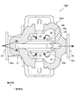
- the centrifugal fluid machine of the present embodiment is a centrifugal pump PMP using a liquid phase fluid such as water as a working fluid, and is composed of a so-called double suction single-bullet centrifugal pump.
- the centrifugal pump PMP of the present embodiment includes a rotating shaft 10, an impeller 20, and a casing 30, and is driven by an electric motor M.
- the rotating shaft 10 is formed in a round bar shape, and is pivotally supported by the casing 30 via the gland packing 32a while penetrating the casing 30.
- the output shaft of the electric motor M is connected to one end of the rotating shaft 10 pivotally supported in this way, and the rotating shaft 10 rotates around the shaft when the electric motor M operates.
- the impeller 20 is integrally fixed around the axis of the rotating shaft 10 and rotates together with the rotating shaft 10. Further, the impeller 20 is composed of a so-called closed impeller in which the main plate 21, the side plate 22, and the blade 23 are integrally formed. In addition, in FIGS. 3 and 4, in order to facilitate understanding of the configuration and operation of the centrifugal pump PMP, the configuration is partially omitted.
- the main plate 21 has a substantially bicone shape formed integrally with two right cones having the same shape facing each other on the bottom surfaces.
- the main plate 21 is fixed in a state where the axis of the rotating shaft 10 penetrates the central axis of the bicone shape. Further, on the main plate 21, a plurality of wings 23 are erected on each conical surface thereof.
- Each of the wings 23 is erected on the conical surface 21a of the main plate 21 with a predetermined height dimension, and each of the wings 23 is in a state of being spaced apart from the conical surface 21a of the main plate 21. , Supports the side plate 22.
- the inner peripheral surface of the side plate 22 has a funnel shape that follows the conical surface shape of the main plate 21, and is overlapped with each conical surface 21a of the main plate 21.
- the impeller 20 is located at two small diameter openings that open around the axis of the rotating shaft 10 and an axially intermediate portion of the rotating shaft 10, and is located outward in the radial direction.
- An opening on the large diameter side that opens in an annular shape toward the surface is formed.
- the region surrounded by the main plate 21, the blade 23, and the side plate 22 is set in the impeller inner flow path 20b.
- two small diameter side openings that open around the axis of the rotating shaft 10 are set at the impeller inlet 20a of the impeller inner flow path 20b.
- the impeller 20 is located in the middle portion in the axial direction, and an opening on the large diameter side that opens in an annular shape toward the outer side in the radial direction is set at the impeller outlet 20c.
- the casing 30 rotatably supports the rotating shaft 10 and the impeller 20 via the gland packing 32a, and forms a flow path for the working fluid.
- the casing 30 includes a case main body 31, a shaft sealing portion 32, a suction portion 33, a suction flow path 34, a supply chamber 35, an impeller accommodating chamber 36, a spiral flow path 37, and a discharge portion 38.
- the arrows in each figure indicate the direction in which the working fluid flows.
- the case body 31 constitutes the outer shell shape of the casing 30, and the impeller 20 is rotatably supported inside the case body 31, and the working fluid circulates inside the case body 31.
- the case main body 31 is configured to be divisible into two members, a lower main body 31L and an upper main body 31U.
- the shaft sealing portion 32 includes a gland packing 32a and a packing retainer 32b.
- the gland packing 32a is configured to rotatably support the rotating shaft 10 around the shaft.
- the packing retainer 32b is configured to prevent leakage of the working fluid from the gap between the rotating shaft 10 and the casing 30.
- the suction portion 33 constitutes an inlet portion for introducing the working fluid into the casing 30 from the outside. Further, the suction portion 33 is provided with a suction side flange 33a as a means for connecting to an external pipe or the like (not shown).
- the suction flow path 34 branches the flow of the working fluid introduced from the suction portion 33 into two on one side and the other side of the rotating shaft 10, and is separated at the branched ends. It leads to the supply room 35. Then, each of the branched suction flow paths 34 swirls from the suction portion 33 toward the supply chamber 35 in a spiral shape centered on the rotation shaft 10.
- each of the supply chambers 35 is formed around the rotation axis 10.
- An impeller accommodating chamber 36 is arranged between the two supply chambers 35. Then, each supply chamber 35 is connected to the impeller accommodating chamber 36, and supplies the working fluid flowing through the suction flow path 34 to the impeller accommodating chamber 36.
- the impeller accommodating chamber 36 is arranged so as to be sandwiched between the two branched suction flow paths 34, and the impeller 20 can be rotated together with the rotating shaft 10. It is housed inside.
- the impeller accommodating chamber 36 is divided into each supply chamber 35 and a spiral flow path 37 by an accommodating wall 36a.
- the accommodating wall 36a is composed of a pair of wall surfaces so as to sandwich the impeller 20 in between. Further, the accommodating wall 36a is formed integrally with the case main body 31 while being curved like a funnel according to the outer shape of the side plate 22 constituting the impeller 20.
- the small diameter side opening of the storage wall 36a is set at the storage chamber entrance 36b, and the large diameter side opening is set at the storage chamber outlet 36c.
- the accommodation chamber entrance 36b has a circular shape set to a diameter slightly larger than that of the impeller entrance 20a so that the impeller entrance 20a is exposed from the accommodation chamber entrance 36b with the impeller 20 accommodated therein. It is an opening.
- a leak prevention means 36d is installed between the inner peripheral edge of the accommodation chamber entrance 36b and the outer peripheral edge of the impeller inlet 20a.
- the leakage prevention means 36d is set to prevent the boosted working fluid discharged from the impeller outlet 20c to the spiral flow path 37 from returning to the supply chamber 35 on the low pressure side, and is composed of a so-called live ring.
- the accommodation chamber outlet 36c is an annular opening in which the large-diameter side openings of the funnel-shaped accommodation walls 36a face each other with the impeller outlet 20c in between to open outward in the radial direction. Is forming.
- the spiral flow path 37 will be described. As shown in FIGS. 1, 2, and 4, the spiral flow path 37 has a spiral shape along the outer circumference of the impeller 20 on the radial outside of the accommodation chamber outlet 36c, that is, on the radial outside of the impeller outlet 20c. Is formed in.
- the spiral flow path 37 constitutes a flow path from the confluence of the working fluids discharged radially outward from the accommodation chamber outlet 36c to the discharge portion 38. The details of the spiral flow path 37 will be described later.
- the discharge unit 38 constitutes an outlet for discharging the working fluid boosted by the centrifugal pump PMP to the outside.
- the discharge unit 38 is provided with a discharge side flange 38a as a means for connecting to an external pipe or the like (not shown).
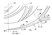
- a straight line hanging from the axis C10 of the rotating shaft 10 is defined as a reference line LB.
- a half straight line that rotates in the counterclockwise direction (hereinafter, referred to as winding direction R) while extending in the radial direction with the axis C10 as the center is defined as the turning line LA, and is referred to as the turning line LA.
- the angle formed by the reference line LB is defined as the winding angle ⁇ .
- the spiral flow path 37 is composed of a spiral portion 41, a diffuser 42, a tongue portion 43, and a communication portion 44.
- the spiral portion 41 includes a pair of side walls 41a and a peripheral wall 41b, and has a substantially trapezoidal cross section.
- the cross-sectional shape of the spiral portion 41 is not limited to a substantially trapezoidal cross section.
- various cross-sectional shapes such as a substantially elliptical shape, a substantially circular shape, and a substantially inverted triangle can be appropriately selected according to the specifications of the centrifugal pump PMP and the like.
- the range of the winding angle ⁇ of the spiral portion 41 from 0 ° to about 40 ° is referred to as the winding start side 37a of the spiral flow path 37.
- the pair of side walls 41a are arranged so as to face each other so that the wall surfaces are along the rotating surface of the impeller 20 and the impeller outlet 20c is sandwiched between them.
- the peripheral wall 41b faces each radial outer edge of the pair of side walls 41a while facing the impeller outlet 20c.
- the diffuser 42 is a pipeline that constitutes the winding end side 37b of the spiral flow path 37 and communicates the winding end of the spiral portion 41 and the discharge portion 38. Further, the diffuser 42 communicates with the winding start side 37a of the spiral portion 41 through the communicating portion 44.
- the tongue portion 43 connects the edge on the starting point side of the peripheral wall 41b and the diffuser 42 while forming a substantially wedge shape that is convex in the direction opposite to the winding direction R.
- the tongue portion 43 is arranged at a position where the starting point side edge of the peripheral wall 41b is set in order to connect the starting point side edge of the peripheral wall 41b and the diffuser 42.
- the thickness dimension T the radial dimension
- the communication portion 44 has a groove shape that connects the winding start side 37a and the winding end side 37b in the radial direction, and the working fluid flows from the winding end side 37b to the winding start side 37a during the operation of the centrifugal pump PMP. It functions as a flow path.
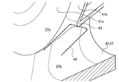
- the groove shape of the communication portion 44 is formed into a substantially V-shaped groove shape in which the groove wall portion is formed by the rectifying protrusions 45 projecting from the inner wall surfaces of the side wall 41a and the groove bottom portion is formed by the tongue portion 43. ing. That is, the communication portion 44 has a groove shape formed by a pair of side walls 41a and a tongue portion 43.
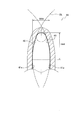
- the substantially V-shaped groove shape of the communication portion 44 is set so that the side wall dimension W44 as the groove width dimension is smaller than the groove depth dimension H44 (the dimension from the groove opening to the groove bottom).
- the bottom of the V-shaped groove is set at a position equidistant from both side walls 41a at the tip of the tongue portion 43.
- the rectifying protrusion 45 is curved in an arc shape along the boundary portion between the winding start side 37a and the winding end side 37b, and projects toward the opposite side wall 41a.
- the V-shaped groove shape of the communication portion 44 of the present embodiment is composed of two circular arcs having different diameters arranged based on the method of the two-arc method. That is, in the V-shaped groove shape, a circle with a small diameter (hereinafter referred to as a small circle CS) is inscribed in a circle with a large diameter (hereinafter referred to as a great circle CL), so that two arcs are smoothly continuous. Forming a shape.
- a small circle CS a circle with a small diameter
- CL large diameter
- the V-shaped groove shape is formed in a line-symmetrical shape having a straight line connecting points located equidistant from both side walls 41a as the axis of symmetry LC. That is, the small circle CS is arranged so that its center is located on the axis of symmetry LC, and forms an arc at the bottom of the groove.
- the V-shaped groove shape formed by the rectifying projection 45 is not limited to the continuous arc formed based on the method of the two-circle arc method as described above, and can be formed into various shapes. Is. Therefore, another aspect of the V-shaped groove shape formed by the rectifying projection 45 will be described later.
- the thickness dimension T (vertical dimension in FIG. 13) of the tongue portion 43 of this comparative example is set so as to be thick in the vicinity of the side wall 41a and thinnest in the center between the side walls. Therefore, as shown in FIG. 13, the tip portion of the tongue portion 43 has a constricted shape when the tongue portion 43 is viewed from the upstream side. Further, the tip portion of the tongue portion 43 is configured as a flat surface along the groove width direction (left-right direction in FIGS. 12 and 13) while facing the upstream side so as to be orthogonal to the flow of the working fluid. ing.
- the pair of side walls 41a is not provided with a configuration corresponding to the rectifying projection 45 in the above-described embodiment. That is, as shown in FIGS. 11 and 12, the communication portion 44 of the comparative example is formed in a rectangular groove shape by the wall surface of the pair of side walls 41a and the tip portion of the tongue portion 43.
- the flow rate to be dammed changes according to the distance from the side wall 41a, a pressure difference is generated on the flat surface of the tip portion of the tongue portion 43, and a secondary flow such as a vortex flow is generated. Is disturbed and stagnant, and distribution resistance increases and worsens. Then, as the flow resistance deteriorates, the working fluid that should be discharged from the spiral portion 41 to the outside through the diffuser 42 will be recirculated to the winding start side 37a of the spiral portion 41 through the communication portion 44. .. That is, in the configuration of the communication portion 44 of the comparative example, since a portion where the flow is stagnant is generated, the amount of recirculation from the winding end side 37b to the winding start side 37a increases, and the operation efficiency decreases.
- the shape of the tip portion of the tongue portion 43 has a constant thickness dimension T from one side wall 41a to the other side wall 41a. It is set. Therefore, when the flow collides with the tip portion of the tongue portion 43, the flow rate dammed by the tip portion of the tongue portion 43 does not vary with respect to the axial dimension of the rotating shaft 10, and the turbulence of the flow is suppressed.
- the communication portion 44 is formed in a V-shaped groove shape. Therefore, while the working fluid is flowing from the spiral portion 41 to the discharge portion 38 through the diffuser 42, a part of the working fluid enters the inside of the V-shaped groove shape from the groove opening of the communication portion 44 toward the groove bottom. Then, as shown in FIG. 7, the working fluid that has entered the inside of the V-shaped groove shape collides diagonally with the groove wall portion in order from the groove opening side (arrow AR1), and finally the groove bottom portion. Collision from the front (arrow AR2).
- the working fluid (arrow AR1) that collides diagonally with the groove wall portion is applied to the groove wall portion and the flowing direction changes. Therefore, the turbulence of the flow is suppressed as compared with the case of the configuration in which the collision occurs from the front and the flow is dammed as in the comparative example. Then, by suppressing the turbulence of the flow, the working fluid flows smoothly to the diffuser 42, so that the flow recirculating from the winding end side 37b to the winding start side 37a through the communication portion 44 is reduced.
- the portion where the working fluid collides from the front is limited to the groove bottom portion, and the working fluid collides diagonally with the remaining portion.
- the turbulence of the flow caused by the working fluid colliding with the tip portion of the tongue portion 43 from the front is suppressed.
- the V-shaped groove shape is formed by setting the rectifying projection 45 on the communicating portion 44, the area communicating in the radial direction is reduced as compared with the case where the rectifying projection is not set. There is.
- the rectifying projection 45 is provided on the groove wall portion and the broken line is broken.
- the V-shaped groove shape shown by is formed.
- the area indicated by the crosshatch CH is closed, and the area in which the winding end side 37b and the winding start side 37a communicate with each other is reduced. Then, by reducing the area of communication, it becomes an obstacle when the working fluid recirculates, and the recirculation flow rate can be reduced.
- the graph of FIG. 14 is a graph showing the difference in the flow rate caused by the difference in the configuration and the function of the communication portion described above for the present embodiment and the comparative example.
- the horizontal axis of the graph is the dimensionless flow rate Q of the working fluid discharged from the discharge unit 38 by the maximum pump efficiency flow rate Qbep.
- the communication portion 44 that communicates the winding start side 37a and the winding end side 37b of the spiral flow path 37 is formed in a substantially V-shaped groove shape by the rectifying projection 45 projecting from the inner wall surface of the groove wall portion.
- the winding start side 37a and the winding end side 37b of the spiral flow path 37 communicate with each other as compared with the case where the communication portion 44 is formed in a rectangular groove shape without the rectifying projection 45.
- the area of the area can be reduced.
- the communication portion 44 has a V-shaped groove shape, so that the flow of the working fluid forms a V-shaped groove shape before colliding with the tip portion (groove bottom portion) of the tongue portion 43. Collide diagonally with the wall. The working fluid collides diagonally with the groove wall portion to change the direction of the flow while stimulating the flow.
- the turbulence of the flow generated when the working fluid passes through the tongue portion 43 is suppressed and the flow is stabilized as compared with the case where the working fluid collides with the tongue portion 43 from the front without the rectifying protrusion 45. be able to.
- the recirculation flow from the winding end side 37b to the winding start side 37a can be reduced, the loss due to the recirculation can be reduced, and the centrifugal pump PMP (centrifugal fluid machine) can be operated stably. it can.
- the V-shaped groove shape of the communication portion 44 is set so that the side wall dimension W44 as the width dimension of the groove opening is smaller than the groove depth dimension.
- the V-shaped groove shape of the communication portion 44 is formed by a smoothly continuous curve. That is, the rectifying protrusion 45 forming the groove wall portion and the tongue portion 43 forming the groove bottom portion are formed so as to be smoothly continuous by a curve formed based on the method of the two-circle arc method.
- the position where the working fluid collides with the rectifying projection 45 gradually moves to the downstream side in the flow direction from the vicinity of the side wall 41a toward the center between the side walls 41a. That is, the positions where the working fluid and the rectifying projection 45 collide are dispersed in the flow direction.
- the groove bottoms forming the V-shaped groove shape of the communication portion 44 are set at positions equidistant from both side walls 41a. That is, when a part of the flow of the working fluid collides with the communication portion 44, the groove bottom portion that collides with the flow from the front is set at a position equidistant from both side walls 41a so as to stop the flow. ..
- the portion where the pressure is highest is formed in the center between the side walls 41a, so that the pressure gradient becomes symmetrical in the direction between the side walls with the center between the side walls 41a as the center, and the flow turbulence is suppressed. Will be done.
- the groove bottom is set at a position close to one side wall 41a, the pressure gradient becomes asymmetrical in the direction between the side walls, so that the flow tends to be turbulent, which causes an increase in the recirculating flow. ..
- the thickness dimension T of the tongue portion 43 is set to be constant between the side walls 41a.
- the groove shape of the V-shaped groove is configured to be asymmetrical. That is, in this embodiment, the left and right groove shapes are formed based on the method of the two-arc method, but the small circles CSa and CSb forming the arc on the groove bottom side and the great circle forming the arc on the groove wall side are formed. The diameters of the circles CLa and CLb are different on the left and right. Further, the groove bottom portion of the V-shaped groove is set at a position equidistant from both side walls 41a at the tip portion of the tongue portion 43, as in the above-described embodiment.
- the thickness dimension T is set constant from one side wall 41a to the other side wall 41a (see FIGS. 8 and 9).
- a groove shape is suitable for a centrifugal pump PMP of a type in which the flow velocities are likely to differ between the left and right, such as a single suction type.
- the groove shape of the V-shaped groove is formed into a symmetrical shape with an arc and a straight line. That is, in this embodiment, the bottom groove portion is formed of an arc and the groove wall portion is formed of a straight line.
- the thickness dimension T is set constant from one side wall 41a to the other side wall 41a (see FIGS. 8 and 9).
- Such a groove shape is suitable when it is desired to make the cross-sectional area of the flow path smaller than the V-shaped groove shape of the above-described embodiment.
- the groove shape of the V-shaped groove is formed to be symmetrical based on the method of the three-circle arc method. That is, in this embodiment, each of the bottom groove portion, the groove wall portion, and the groove opening is composed of three circles (small circle CS, medium circle CM, great circle CL) having different diameters, and the arcs are in contact with each other. It is continuous. Further, the diameters of the three circles (small circle CS, medium circle CM, great circle CL) are set so that the diameters of the arcs increase in the order of the bottom groove portion, the groove wall portion, and the groove opening portion.
- the thickness dimension T is set constant from one side wall 41a to the other side wall 41a (see FIGS. 8 and 9).
- Such a groove shape is suitable when it is desired to set the groove wall shape more finely than the rectifying protrusion 45 of the above-described embodiment, or when it is desired to make the portion of the rectifying protrusion 45 protruding from the side wall 41a more smoothly. Is.
- the groove shape of the V-shaped groove is symmetrically configured by using an ellipse. That is, in this embodiment, the groove shape is represented by one mathematical formula.
- the thickness dimension T is set constant from one side wall 41a to the other side wall 41a (see FIGS. 8 and 9).
- Such a groove shape makes the groove opening and the side wall 41a smoother when it is desired to make the cross-sectional area of the flow path smaller than the V-shaped groove shape of the above-described embodiment, or when it is desired to make the groove wall shape continuous more smoothly. It is suitable when you want to make it continuous.
- the groove shape of the V-shaped groove is symmetrically configured by using a quadratic curve. That is, in this embodiment, the groove shape is represented by one mathematical formula.
- the thickness dimension T is set constant from one side wall 41a to the other side wall 41a (see FIGS. 8 and 9).
- Such a groove shape is suitable when it is desired to make the cross-sectional area of the flow path smaller than the V-shaped groove shape of the above-described embodiment, or when it is desired to make the groove wall portion shape more smooth and continuous.
- ⁇ Sixth alternative mode> (Bezier curve)
- the groove shape of the V-shaped groove is formed to be symmetrical by using a Bezier curve (spline curve).
- a Bezier curve is a mathematical formula used to draw a curve on a computer, and expresses a curve based on a plurality of set definition point PTs.
- the definition points PT1 and PT5 of the groove opening are designated as the start point and the end point of the curve, and the groove shape is defined by the remaining definition points PT2 to PT4 (direction points).
- the thickness dimension T is set constant from one side wall 41a to the other side wall 41a (see FIGS. 8 and 9).
- Such a groove shape is suitable when it is desired to set an arbitrary shape different from the V-shaped groove shape of the above-described embodiment, or when it is desired to make the groove wall portion and the side wall 41a more smoothly continuous.
- the groove shape of the V-shaped groove is formed in a stepped shape and a symmetrical shape. That is, in this embodiment, the groove wall portion and the groove bottom portion are configured in a stepped shape.
- the thickness dimension T is set constant from one side wall 41a to the other side wall 41a (see FIGS. 8 and 9).
- Such a groove shape is suitable when it is difficult to smoothly continue the V-shaped groove shape, such as when the capacity of the centrifugal pump PMP is relatively large or the size of the casing 30 is relatively large.
- the groove shape of the V-shaped groove is symmetrically configured by using a normal distribution curve. That is, in this embodiment, the groove shape is represented by one mathematical formula.
- the thickness dimension T is set constant from one side wall 41a to the other side wall 41a (see FIGS. 8 and 9).
- Such a groove shape is suitable when it is desired to make the cross-sectional area of the flow path smaller than the V-shaped groove shape of the above-described embodiment.
- the centrifugal fluid machine to which the present invention can be applied is not limited to this.
- it can be used for a single suction pump that sucks working fluid from one side in the axial direction of the rotating shaft, a multi-stage pump, a vertical pump such as a line pump, a variable speed operation pump in which the rotation speed of the electric motor M can be changed, and the like. ..
- a pump turbine or the like that drives a generator by rotating an impeller with the force of a working fluid.
- a liquid phase fluid such as water is adopted as the working fluid
- a gas phase fluid such as air can be adopted as a working fluid. That is, the present invention can be adopted as long as the centrifugal fluid machine is provided with a spiral flow path 37 in which the winding start side 37a and the winding end side 37b communicate with each other via the communication portion 44. The same action and effect as above can be obtained.
Landscapes
- Engineering & Computer Science (AREA)
- Mechanical Engineering (AREA)
- General Engineering & Computer Science (AREA)
- Structures Of Non-Positive Displacement Pumps (AREA)
Abstract
羽根車(20)の回転面に沿って対向配置された一対の側壁(41a)と、一対の側壁(41a)の径方向外側縁部を跨ぐように連結しつつ、羽根車(20)の外周近傍を起点とし、羽根車(20)の外周に沿いつつ、羽根車(20)の外周から径方向外側へ徐々に離れる渦巻形状を呈する周壁(41b)と、周壁(41b)の起点側端縁に、周壁(41b)の巻き方向(R)とは逆向きに凸の略くさび形状を有する舌部(43)と、一対の側壁(41a)と舌部(43)とによって、巻始め側(37a)と巻終わり側(37b)とを連通する略V字溝形状に構成された連通部(44)と、によって渦巻状に形成された渦巻流路(37)を遠心式流体機械に設ける。これにより、脈動の発生を抑制して、安定した運転を行いつつ、再循環による損失を低減することができる遠心式流体機械を提供する。
Description
本発明は、遠心式羽根車と渦巻状ケーシングを備える遠心式流体機械に関する。
遠心ポンプなどの遠心式流体機械では、運転を安定させるために、従来から様々な手法が提案されている。
たとえば、特許文献1の遠心ポンプでは、渦巻状ケーシング内に形成されるスクロール流路について、舌部に近接する巻終わり部分の側壁に再循環路が設定されている。
そして、再循環路を設定することで、脈動などの不安定現象が起きやすい運転領域での安定した運転がもたらされる。
たとえば、特許文献1の遠心ポンプでは、渦巻状ケーシング内に形成されるスクロール流路について、舌部に近接する巻終わり部分の側壁に再循環路が設定されている。
そして、再循環路を設定することで、脈動などの不安定現象が起きやすい運転領域での安定した運転がもたらされる。
両吸込うず巻ポンプの圧力脈動に関する実験的研究 ターボ機械第13巻第6号、P.21~29 大野隆史、田中康夫、小松厚造、紺野大輔
ところで、特許文献1では、舌部の断面形状が、巻始め近傍で大きく拡大しているため、流れの急激な変化による拡大損失、剥離により損失の増大が懸念される。
また、非特許文献1には、舌部の先端が、羽根車に接近するほど、再循環流れが減少すること、舌部の先端が羽根車に接近しすぎた場合には、舌部と羽根車後縁、および後縁流れとの干渉が増大し、脈動、騒音、サージなどの不都合が生じること、が示されている。
また、非特許文献1には、舌部の先端が、羽根車に接近するほど、再循環流れが減少すること、舌部の先端が羽根車に接近しすぎた場合には、舌部と羽根車後縁、および後縁流れとの干渉が増大し、脈動、騒音、サージなどの不都合が生じること、が示されている。
本発明は、前述の課題に鑑みて創案されたものであり、脈動の発生を抑制して、安定した運転を行いつつ、再循環による損失を低減することができる遠心式流体機械を提供することを目的とする。
前記の目的を達成するために、本発明に係る遠心式流体機械は、回転軸を介して、羽根車を回転可能に軸支するケース本体と、該羽根車の径方向外側に、該羽根車の外周に沿って、渦巻状に形成された渦巻流路と、を具備するケーシングを備え、該渦巻流路は、該羽根車の回転面に沿って対向配置された一対の側壁と、該一対の側壁の径方向外側縁部を跨ぐように連結しつつ、該羽根車の外周近傍を起点とし、該羽根車の外周に沿って巻き方向へ延在しつつ、該羽根車の外周から径方向外側へ徐々に離れる渦巻形状を呈する周壁と、該周壁の起点側端縁に、該周壁の巻き方向とは逆向きに凸の略くさび形状を有する舌部と、該一対の側壁と該舌部とによって、巻始め側と巻終わり側とを連通する溝形状に構成された連通部と、を備えた遠心式流体機械であって、該連通部は、略V字溝形状に形成されたことを特徴とする。
本発明によれば、脈動の発生を抑制して、安定した運転を行いつつ、再循環による損失を低減することができる遠心式流体機械を提供することができる。
本発明の実施形態について、適宜図面を参照しながら詳細に説明する。同一の構成要素には同一の符号を付し、重複する説明を省略する。
図1、図2に示すように、本実施形態の遠心式流体機械は、水などの液相流体を作動流体とする遠心ポンプPMPであり、いわゆる両吸込単弾渦巻ポンプで構成されている。
図1、図2に示すように、本実施形態の遠心式流体機械は、水などの液相流体を作動流体とする遠心ポンプPMPであり、いわゆる両吸込単弾渦巻ポンプで構成されている。
本実施形態の遠心ポンプPMPは、回転軸10、羽根車20、ケーシング30を備え、電動モータMによって駆動する。
回転軸10は、図1、図2に示すように、丸棒形状に形成され、ケーシング30を貫きつつ、グランドパッキン32aを介して、ケーシング30に軸支されている。
このように軸支された回転軸10は、その一端に電動モータMの出力軸が連結されており、電動モータMが稼働することで、軸周りに回転する。
回転軸10は、図1、図2に示すように、丸棒形状に形成され、ケーシング30を貫きつつ、グランドパッキン32aを介して、ケーシング30に軸支されている。
このように軸支された回転軸10は、その一端に電動モータMの出力軸が連結されており、電動モータMが稼働することで、軸周りに回転する。
羽根車20は、図2~図4に示すように、回転軸10の軸周りに一体に固定され、回転軸10とともに回転する。
また、羽根車20は、主板21、側板22、翼23が一体に形成された、いわゆるクローズド形羽根車で構成されている。
なお、図3、図4では、遠心ポンプPMPの構成、および働きの理解を容易にするため、構成を一部省略して描いている。
また、羽根車20は、主板21、側板22、翼23が一体に形成された、いわゆるクローズド形羽根車で構成されている。
なお、図3、図4では、遠心ポンプPMPの構成、および働きの理解を容易にするため、構成を一部省略して描いている。
主板21は、同一形状を有する2つの直円錐が底面同士で対向した状態で、一体に形成された略双円錐形状を備えている。
そして、主板21は、回転軸10の軸心が双円錐形状の中心軸を貫いた状態で、固定されている。
また、主板21には、その各円錐面上に、複数の翼23が立設している。
そして、主板21は、回転軸10の軸心が双円錐形状の中心軸を貫いた状態で、固定されている。
また、主板21には、その各円錐面上に、複数の翼23が立設している。
翼23は、それぞれが、所定の高さ寸法で主板21の円錐面21a上に立設されており、各翼23は、主板21の円錐面21aとの間に所定の間隔を空けた状態で、側板22を支えている。
側板22は、その内周面が、主板21の円錐面形状に倣った漏斗形状を備え、主板21の各円錐面21aに重ねられている。
側板22は、その内周面が、主板21の円錐面形状に倣った漏斗形状を備え、主板21の各円錐面21aに重ねられている。
以上のように構成することで、羽根車20には、回転軸10の軸周りに開口する小径側の2つの開口部と、回転軸10の軸方向の中間部に位置し、径方向外側に向かって円環状に開口する大径側の開口部と、が形成される。
そして、羽根車20は、主板21、翼23、側板22で囲まれた領域が、羽根車内流路20bに設定されている。
そして、羽根車20は、主板21、翼23、側板22で囲まれた領域が、羽根車内流路20bに設定されている。
また、回転軸10の軸周りに開口する小径側の2つの開口部が、羽根車内流路20bの羽根車入口20aに設定されている。
さらに、羽根車20は、その軸方向の中間部に位置し、径方向外側に向かって円環状に開口する大径側の開口部が、羽根車出口20cに設定されている。
さらに、羽根車20は、その軸方向の中間部に位置し、径方向外側に向かって円環状に開口する大径側の開口部が、羽根車出口20cに設定されている。
電動モータMが、羽根車20を回すことで、羽根車20内部の作動流体が、遠心力によって、羽根車出口20cから排出される。そして、作動流体が羽根車出口20cから排出されることで、減圧する羽根車入口20aには、後述する供給室35から作動流体が流入する。
ケーシング30は、図1~図4に示すように、グランドパッキン32aを介して、回転軸10、羽根車20を回転可能に軸支するとともに、作動流体の流通経路を形成している。
また、ケーシング30は、ケース本体31、軸封部32、吸込部33、吸込流路34、供給室35、羽根車収容室36、渦巻流路37、吐出部38を備えている。
なお、各図中の矢印は、作動流体の流れる方向を示している。
また、ケーシング30は、ケース本体31、軸封部32、吸込部33、吸込流路34、供給室35、羽根車収容室36、渦巻流路37、吐出部38を備えている。
なお、各図中の矢印は、作動流体の流れる方向を示している。
ケース本体31は、図1~図4に示すように、ケーシング30の外殻形状を構成し、その内部に羽根車20を回転可能に軸支するとともに、その内部を作動流体が循環する。
ケース本体31は、下側本体31L、上側本体31Uの2部材に分割可能に構成されている。
軸封部32は、図2に示すように、グランドパッキン32a、パッキン押さえ32bを備えている。
グランドパッキン32aは、回転軸10を軸周りに回転可能に支持するための構成である。
パッキン押さえ32bは、回転軸10とケーシング30との間の隙間からの作動流体の漏出を防止するための構成である。
ケース本体31は、下側本体31L、上側本体31Uの2部材に分割可能に構成されている。
軸封部32は、図2に示すように、グランドパッキン32a、パッキン押さえ32bを備えている。
グランドパッキン32aは、回転軸10を軸周りに回転可能に支持するための構成である。
パッキン押さえ32bは、回転軸10とケーシング30との間の隙間からの作動流体の漏出を防止するための構成である。
次に、吸込部33について説明する。
吸込部33は、図1、図3に示すように、外部からケーシング30内へ作動流体を導入するための入口部分を構成している。
また、吸込部33には、図外の外部配管等に連結する手段として、吸込側フランジ33aが設けられている。
吸込流路34は、図1~図3に示すように、吸込部33から導入された作動流体の流れを回転軸10の一側と他側の2本に分岐し、分岐した先で別々の供給室35に通じている。そして、分岐した各吸込流路34は、吸込部33から供給室35に向かって、回転軸10を中心とする渦巻状に旋回している。
吸込部33は、図1、図3に示すように、外部からケーシング30内へ作動流体を導入するための入口部分を構成している。
また、吸込部33には、図外の外部配管等に連結する手段として、吸込側フランジ33aが設けられている。
吸込流路34は、図1~図3に示すように、吸込部33から導入された作動流体の流れを回転軸10の一側と他側の2本に分岐し、分岐した先で別々の供給室35に通じている。そして、分岐した各吸込流路34は、吸込部33から供給室35に向かって、回転軸10を中心とする渦巻状に旋回している。
供給室35は、図2、図3に示すように、それぞれが回転軸10周りに形成されている。
また、2つの供給室35の間には、羽根車収容室36が配置されている。
そして、各供給室35は、羽根車収容室36に通じており、吸込流路34を流通してきた作動流体を羽根車収容室36へ供給する。
羽根車収容室36は、図2、図3に示すように、分岐した2本の吸込流路34の間に挟まれるように配置されており、羽根車20を回転軸10とともに回転可能な状態で内部に収容している。
また、2つの供給室35の間には、羽根車収容室36が配置されている。
そして、各供給室35は、羽根車収容室36に通じており、吸込流路34を流通してきた作動流体を羽根車収容室36へ供給する。
羽根車収容室36は、図2、図3に示すように、分岐した2本の吸込流路34の間に挟まれるように配置されており、羽根車20を回転軸10とともに回転可能な状態で内部に収容している。
また、羽根車収容室36は、収容壁36aによって、各供給室35と、渦巻流路37とに区画されている。
収容壁36aは、羽根車20を間に挟むように一対の壁面で構成されている。
また、収容壁36aは、羽根車20を構成する側板22の外形形状に倣って漏斗状に湾曲しつつ、ケース本体31と一体に形成されている。
そして、収容壁36aは、小径側の開口部が収容室入口36b、大径側の開口部が収容室出口36c、にそれぞれ設定されている。
収容壁36aは、羽根車20を間に挟むように一対の壁面で構成されている。
また、収容壁36aは、羽根車20を構成する側板22の外形形状に倣って漏斗状に湾曲しつつ、ケース本体31と一体に形成されている。
そして、収容壁36aは、小径側の開口部が収容室入口36b、大径側の開口部が収容室出口36c、にそれぞれ設定されている。
収容室入口36bは、その内部に羽根車20が収容された状態で、収容室入口36bから羽根車入口20aが露出するように、羽根車入口20aよりもひとまわり大きな径に設定された円形の開口部である。
収容室入口36bの内周縁と羽根車入口20aの外周縁との間には、漏止手段36dが設置されている。
収容室入口36bの内周縁と羽根車入口20aの外周縁との間には、漏止手段36dが設置されている。
漏止手段36dは、羽根車出口20cから渦巻流路37へ吐出された昇圧後の作動流体が、低圧側の供給室35へ戻ることを防止するために設定されており、いわゆるライブリングで構成されている。
収容室出口36cは、漏斗形状を形成する各収容壁36aの大径側開口部が、羽根車出口20cを間に挟みつつ、互いに対峙することで、径方向外側に開口する円環状の開口部を形成している。
収容室出口36cは、漏斗形状を形成する各収容壁36aの大径側開口部が、羽根車出口20cを間に挟みつつ、互いに対峙することで、径方向外側に開口する円環状の開口部を形成している。
次に、渦巻流路37について説明する。
渦巻流路37は、図1、図2、図4に示すように、収容室出口36cの径方向外側、つまり羽根車出口20cの径方向外側に、羽根車20の外周に沿って、渦巻状に形成されている。
渦巻流路37は、収容室出口36cから径方向外側へ吐出された作動流体が合流してから、吐出部38までの流路を構成している。
なお、渦巻流路37の詳細については後述する。
渦巻流路37は、図1、図2、図4に示すように、収容室出口36cの径方向外側、つまり羽根車出口20cの径方向外側に、羽根車20の外周に沿って、渦巻状に形成されている。
渦巻流路37は、収容室出口36cから径方向外側へ吐出された作動流体が合流してから、吐出部38までの流路を構成している。
なお、渦巻流路37の詳細については後述する。
吐出部38は、遠心ポンプPMPが昇圧した作動流体を外部へ吐出するための出口を構成している。
吐出部38には、図外の外部配管等に連結する手段として、吐出側フランジ38aが設けられている。
吐出部38には、図外の外部配管等に連結する手段として、吐出側フランジ38aが設けられている。
次に、渦巻流路37について説明する(図2~図10参照)。
なお、本実施形態のケーシング30の渦巻流路37では、図4において、回転軸10の軸心C10から垂下した直線を基準線LBと定義する。
また、本実施形態では、軸心C10を中心として、径方向に延出しつつ、反時計方向(以下、巻き方向Rと称する)に回転する半直線を旋回線LAと定義し、旋回線LAと基準線LBとのなす角度を巻角度θと定義する。
そして、巻角度θ=0°を渦巻流路37の巻始めに設定するとともに、巻き方向Rに1周(巻角度θ=360°)したところを渦巻流路37の巻終わりに設定する。
なお、本実施形態のケーシング30の渦巻流路37では、図4において、回転軸10の軸心C10から垂下した直線を基準線LBと定義する。
また、本実施形態では、軸心C10を中心として、径方向に延出しつつ、反時計方向(以下、巻き方向Rと称する)に回転する半直線を旋回線LAと定義し、旋回線LAと基準線LBとのなす角度を巻角度θと定義する。
そして、巻角度θ=0°を渦巻流路37の巻始めに設定するとともに、巻き方向Rに1周(巻角度θ=360°)したところを渦巻流路37の巻終わりに設定する。
渦巻流路37は、図2~図4に示すように、渦巻部41、ディフューザ42、舌部43、連通部44で構成されている。
渦巻部41は、図2、図3に示すように、一対の側壁41a、周壁41bを備え、断面略台形形状を呈している。
なお、渦巻部41の断面形状は、断面略台形形状に限定されるものではない。たとえば、略楕円形、略円形、略逆三角形などのように、遠心ポンプPMPの仕様などに合わせて、様々な断面形状を適宜選択することが可能である。
渦巻部41は、図2、図3に示すように、一対の側壁41a、周壁41bを備え、断面略台形形状を呈している。
なお、渦巻部41の断面形状は、断面略台形形状に限定されるものではない。たとえば、略楕円形、略円形、略逆三角形などのように、遠心ポンプPMPの仕様などに合わせて、様々な断面形状を適宜選択することが可能である。
また、渦巻部41の巻角度θ=0°~約40°(舌部43の突端部分の巻角度)の範囲を渦巻流路37の巻始め側37aと称する。
一対の側壁41aは、各壁面が羽根車20の回転面に沿いつつ、羽根車出口20cを間に挟むように、対向配置されている。
周壁41bは、羽根車出口20cに面しつつ、一対の側壁41aの各径方向外側縁部を連結している。
一対の側壁41aは、各壁面が羽根車20の回転面に沿いつつ、羽根車出口20cを間に挟むように、対向配置されている。
周壁41bは、羽根車出口20cに面しつつ、一対の側壁41aの各径方向外側縁部を連結している。
つまり、周壁41bは、羽根車出口20cを跨ぐように、一対の側壁41aを連結している。
さらに、周壁41bは、周方向には巻角度θ=約40°の位置、径方向には運転時に脈動が発生しない程度に、収容室出口36cに近接した位置を起点にして形成されている。
また、周壁41bは、起点から巻角度θ=360°まで羽根車20の外周を巻き方向Rに回転しつつ、羽根車20の外周から徐々に離れるように延びる、渦巻形状を形成している。
さらに、周壁41bは、周方向には巻角度θ=約40°の位置、径方向には運転時に脈動が発生しない程度に、収容室出口36cに近接した位置を起点にして形成されている。
また、周壁41bは、起点から巻角度θ=360°まで羽根車20の外周を巻き方向Rに回転しつつ、羽根車20の外周から徐々に離れるように延びる、渦巻形状を形成している。
ディフューザ42は、図4に示すように、渦巻流路37の巻終わり側37bを構成し、渦巻部41の巻終わりと吐出部38とを連通する管路である。
また、ディフューザ42は、連通部44を通じて、渦巻部41の巻始め側37aに連通している。
舌部43は、図3~図9に示すように、巻き方向Rとは逆向きに凸の略くさび形状を形成しつつ、周壁41bの起点側端縁とディフューザ42とを連結している。
そして、舌部43は、周壁41bの起点側端縁とディフューザ42とを連結するため、周壁41bの起点側端縁が設定された位置に配置されている。
また、ディフューザ42は、連通部44を通じて、渦巻部41の巻始め側37aに連通している。
舌部43は、図3~図9に示すように、巻き方向Rとは逆向きに凸の略くさび形状を形成しつつ、周壁41bの起点側端縁とディフューザ42とを連結している。
そして、舌部43は、周壁41bの起点側端縁とディフューザ42とを連結するため、周壁41bの起点側端縁が設定された位置に配置されている。
つまり、舌部43は、周方向には巻角度θ=約40°の位置、径方向には運転時に脈動が発生しない程度に、羽根車20の外周から間隔を空けた位置に設定されている(図4、図5参照)。
また、舌部43は、回転軸10の軸方向に沿って、両側壁41aの壁面に直交するように、両側壁41aの間に形成されている(図8、図9参照)。
さらに、舌部43は、側壁41a間で回転軸10の径方向の寸法(以下、厚み寸法Tと称する)が一定となるように、設定されている。
また、舌部43は、回転軸10の軸方向に沿って、両側壁41aの壁面に直交するように、両側壁41aの間に形成されている(図8、図9参照)。
さらに、舌部43は、側壁41a間で回転軸10の径方向の寸法(以下、厚み寸法Tと称する)が一定となるように、設定されている。
連通部44は、巻始め側37aと巻終わり側37bとを径方向に連通する溝形状を備え、遠心ポンプPMPの運転中に、巻終わり側37bから巻始め側37aへ作動流体が流れ込む再循環流の流路として機能している。
連通部44は、巻始め側37aの連通方向外側に巻終わり側37bが重なる部位(巻角度θ=0°~約40°(舌部43の突端部分))の巻始め側37aと巻終わり側37bとの境界部分に設定されている。
連通部44は、巻始め側37aの連通方向外側に巻終わり側37bが重なる部位(巻角度θ=0°~約40°(舌部43の突端部分))の巻始め側37aと巻終わり側37bとの境界部分に設定されている。
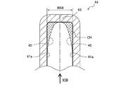
連通部44の溝形状は、溝壁部が両側壁41aの内壁面に突設された整流突起45によって構成されつつ、溝底部が舌部43によって構成された、略V字溝形状に形成されている。
つまり、連通部44は、一対の側壁41aと舌部43とによって溝形状が構成されている。
つまり、連通部44は、一対の側壁41aと舌部43とによって溝形状が構成されている。
また、連通部44の略V字溝形状は、溝幅寸法としての側壁間寸法W44が、溝深さ寸法H44(溝開口部から溝底部の寸法)よりも小さくなるように設定されている。
さらに、連通部44は、溝開口部が巻角度θ=0°、溝底部が巻角度θ=約40°(舌部43の突端部分)に設定されたV字溝で形成されている。
そして、V字溝の溝底部は、舌部43の突端部分における、両側壁41aから等距離の位置に設定されている。
さらに、連通部44は、溝開口部が巻角度θ=0°、溝底部が巻角度θ=約40°(舌部43の突端部分)に設定されたV字溝で形成されている。
そして、V字溝の溝底部は、舌部43の突端部分における、両側壁41aから等距離の位置に設定されている。
整流突起45は、巻始め側37aと巻終わり側37bとの境界部分に沿って円弧状に湾曲しつつ、対向する側壁41aに向かって突設されている。
整流突起45の突出寸法L45は、巻角度θ=0°から巻角度θが大きくなるにつれて徐々に増大し、舌部43の突端部分(巻角度θ=約40°)で、両側壁41a間の中央に到達するように設定されている。
整流突起45の突出寸法L45は、巻角度θ=0°から巻角度θが大きくなるにつれて徐々に増大し、舌部43の突端部分(巻角度θ=約40°)で、両側壁41a間の中央に到達するように設定されている。
また、整流突起45は、厚み寸法Tが、巻角度θ=0°から巻角度θが大きくなるにつれて徐々に増大し、巻角度θ=約40°で、舌部43の突端部分に連続するように設定されている。
そして、整流突起45と舌部43とが連続する部位は、段差なく、滑らかに、且つ一体に形成されている。
また、整流突起45は、その厚み寸法Tが、回転軸10の軸方向に対して、一定となるように設定されている。
そして、整流突起45と舌部43とが連続する部位は、段差なく、滑らかに、且つ一体に形成されている。
また、整流突起45は、その厚み寸法Tが、回転軸10の軸方向に対して、一定となるように設定されている。
次に、V字溝形状について詳細に説明する(図10参照)。
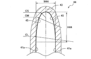
本実施形態の連通部44のV字溝形状は、二円弧法の手法に基づいて配置された、径の異なる2つの円の円弧によって構成されている。
つまり、V字溝形状は、径の小さな円(以下、小円CSと称する)が、径の大きな円(以下、大円CLと称する)に内接することで、2つの円弧が滑らかに連続した形を形成している。
本実施形態の連通部44のV字溝形状は、二円弧法の手法に基づいて配置された、径の異なる2つの円の円弧によって構成されている。
つまり、V字溝形状は、径の小さな円(以下、小円CSと称する)が、径の大きな円(以下、大円CLと称する)に内接することで、2つの円弧が滑らかに連続した形を形成している。
また、V字溝形状は、両側壁41aから等距離に位置する点を結んだ直線を対称軸LCとする線対称形状に形成されている。
つまり、小円CSは、その中心が、対称軸LC上に位置するように配置されるとともに、溝底部の円弧を構成している。
つまり、小円CSは、その中心が、対称軸LC上に位置するように配置されるとともに、溝底部の円弧を構成している。
また、大円CLは、溝壁部の円弧を構成し、溝開口部と、小円CSと、の計2箇所に接している。
なお、整流突起45によって形成されるV字溝形状は、上述のような二円弧法の手法に基づいて構成された連続する円弧に限定されるものではなく、様々な形状に形成することが可能である。
そこで、整流突起45によって形成されるV字溝形状の別態様については、後述する。
なお、整流突起45によって形成されるV字溝形状は、上述のような二円弧法の手法に基づいて構成された連続する円弧に限定されるものではなく、様々な形状に形成することが可能である。
そこで、整流突起45によって形成されるV字溝形状の別態様については、後述する。
<比較例>(図11~図13参照)
次に、本実施形態に対する比較例について説明する。
比較例を例示することで、本実施形態の連通部44の構成、および特徴を明確にし、理解を容易にする。
なお、比較例として例示したケーシング30は、本実施形態の連通部44を見いだすにあたり、ベースとして採用した形態である。
次に、本実施形態に対する比較例について説明する。
比較例を例示することで、本実施形態の連通部44の構成、および特徴を明確にし、理解を容易にする。
なお、比較例として例示したケーシング30は、本実施形態の連通部44を見いだすにあたり、ベースとして採用した形態である。
比較例と前述の実施形態とで異なる構成は、舌部の構成、連通部の構成の2点である。<<舌部の構成>>
本比較例の舌部43の厚み寸法T(図13における上下方向の寸法)は、側壁41a近傍で厚く、側壁間中央で最も薄くなるように設定されている。
このため、図13に示すように、舌部43の突端部分は、舌部43を上流側から見た場合に、くびれ形状を呈している。
また、舌部43の突端部分は、作動流体の流れに対して直交するように、上流側に面しつつ、溝幅方向(図12、図13における左右方向)に沿った平坦面に構成されている。
本比較例の舌部43の厚み寸法T(図13における上下方向の寸法)は、側壁41a近傍で厚く、側壁間中央で最も薄くなるように設定されている。
このため、図13に示すように、舌部43の突端部分は、舌部43を上流側から見た場合に、くびれ形状を呈している。
また、舌部43の突端部分は、作動流体の流れに対して直交するように、上流側に面しつつ、溝幅方向(図12、図13における左右方向)に沿った平坦面に構成されている。
<<連通部の構成>>
本比較例の連通部44には、一対の側壁41aに、前述の実施形態における整流突起45に相当する構成が設定されていない。
つまり、図11、図12に示すように、比較例の連通部44は、一対の側壁41aの壁面と舌部43の突端部分とによって、矩形溝形状に形成されている。
本比較例の連通部44には、一対の側壁41aに、前述の実施形態における整流突起45に相当する構成が設定されていない。
つまり、図11、図12に示すように、比較例の連通部44は、一対の側壁41aの壁面と舌部43の突端部分とによって、矩形溝形状に形成されている。
<<連通部の働き>>
連通部44が、前述のような矩形溝形状を形成していることで、作動流体は、渦巻部41からディフューザ42へ抜ける際、舌部43の突端部分の平坦面に正面から衝突し、その一部がせき止められる。
そして、舌部43がくびれ形状を形成しているために、作動流体が舌部43の突端部分に衝突した際に、せき止められる作動流体の流量が、側壁41a近傍では、側壁間中央よりも大きくなる。
連通部44が、前述のような矩形溝形状を形成していることで、作動流体は、渦巻部41からディフューザ42へ抜ける際、舌部43の突端部分の平坦面に正面から衝突し、その一部がせき止められる。
そして、舌部43がくびれ形状を形成しているために、作動流体が舌部43の突端部分に衝突した際に、せき止められる作動流体の流量が、側壁41a近傍では、側壁間中央よりも大きくなる。
さらに、せき止められる流量が、側壁41aからの距離に応じて変化するため、舌部43の突端部分の平坦面上に圧力差が生じ、渦流れなどの二次流れが発生するなどして、流れが乱れて滞り、流通抵抗が増大、悪化する。
そして、流通抵抗が悪化することで、渦巻部41からディフューザ42を通じて外部へ吐出されるはずの作動流体が、連通部44を通じて、渦巻部41の巻始め側37aへ再循環してしまうことになる。
つまり、比較例の連通部44の構成では、流れの滞る部位が発生するために、巻終わり側37bから巻始め側37aへの再循環量が増加し、運転効率が低下する。
そして、流通抵抗が悪化することで、渦巻部41からディフューザ42を通じて外部へ吐出されるはずの作動流体が、連通部44を通じて、渦巻部41の巻始め側37aへ再循環してしまうことになる。
つまり、比較例の連通部44の構成では、流れの滞る部位が発生するために、巻終わり側37bから巻始め側37aへの再循環量が増加し、運転効率が低下する。
<本実施形態の連通部44の働き>(図5~図10参照)
前述の比較例に対して、本実施形態では、舌部43の突端部分の形状は、図8、図9に示すように、一方の側壁41aから他方の側壁41aにかけて、厚み寸法Tが一定に設定されている。
このため、流れが舌部43の突端部分に衝突した際に、回転軸10の軸方向の寸法について、舌部43の突端部分にせき止められる流量にばらつきがなくなり、流れの乱れが抑制される。
前述の比較例に対して、本実施形態では、舌部43の突端部分の形状は、図8、図9に示すように、一方の側壁41aから他方の側壁41aにかけて、厚み寸法Tが一定に設定されている。
このため、流れが舌部43の突端部分に衝突した際に、回転軸10の軸方向の寸法について、舌部43の突端部分にせき止められる流量にばらつきがなくなり、流れの乱れが抑制される。
また、本実施形態では、図6、図7に示すように、連通部44がV字溝形状に形成されている。このため、作動流体は、渦巻部41からディフューザ42を通じて吐出部38へ抜ける途中に、その一部が連通部44の溝開口部から溝底部に向かってV字溝形状の内部に進入する。
そして、図7に示すように、V字溝形状の内部に進入した作動流体は、溝開口部側から順に、溝壁部に対して斜めに衝突していき(矢印AR1)、最後に溝底部で正面から衝突する(矢印AR2)。
そして、図7に示すように、V字溝形状の内部に進入した作動流体は、溝開口部側から順に、溝壁部に対して斜めに衝突していき(矢印AR1)、最後に溝底部で正面から衝突する(矢印AR2)。
溝壁部に対して斜めに衝突した作動流体(矢印AR1)は、溝壁部にいなされて、流れる方向が変化する。
このため、比較例のように、正面から衝突し、流れがせき止められるような構成の場合よりも、流れの乱れが抑制される。
そして、流れの乱れが抑制されることで、作動流体はディフューザ42へ滞りなく流れるため、連通部44を通じて巻終わり側37bから巻始め側37aへ再循環する流れが減少する。
このため、比較例のように、正面から衝突し、流れがせき止められるような構成の場合よりも、流れの乱れが抑制される。
そして、流れの乱れが抑制されることで、作動流体はディフューザ42へ滞りなく流れるため、連通部44を通じて巻終わり側37bから巻始め側37aへ再循環する流れが減少する。
つまり、V字溝形状の場合、作動流体が正面からの衝突する部位は、溝底部に限定され、残りの部位は、作動流体が斜めに衝突する。
これによって、作動流体が舌部43の突端部分に正面からの衝突することに起因する流れの乱れが抑制される。
また、本実施形態では、連通部44に整流突起45を設定することで、V字溝形状を形成しているため、整流突起が設定されない場合よりも、径方向に連通する面積が縮小している。
これによって、作動流体が舌部43の突端部分に正面からの衝突することに起因する流れの乱れが抑制される。
また、本実施形態では、連通部44に整流突起45を設定することで、V字溝形状を形成しているため、整流突起が設定されない場合よりも、径方向に連通する面積が縮小している。
たとえば、図12に示すように、実線で示された、ベースとなる矩形溝形状の連通部44に対して、本実施形態の連通部44では、溝壁部に整流突起45を設けて、破線で示すV字溝形状を形成している。
これによって、クロスハッチCHで示される領域が塞がれて、巻終わり側37bと巻始め側37aとを連通する面積が縮小する。
そして、連通する面積が縮小することによって、作動流体が再循環する際の妨げとなり、再循環流量を低減することができる。
これによって、クロスハッチCHで示される領域が塞がれて、巻終わり側37bと巻始め側37aとを連通する面積が縮小する。
そして、連通する面積が縮小することによって、作動流体が再循環する際の妨げとなり、再循環流量を低減することができる。
<実施形態と比較例との比較>(図14参照)
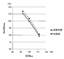
図14のグラフは、本実施形態と比較例とについて、前述の連通部の構成、および働きの違いによって生じる流量の差異を表したグラフである。
グラフの横軸は、吐出部38から吐出される作動流体の流量Qを、最大ポンプ効率流量Qbepによって無次元化したものである。
また、グラフの縦軸は、巻角度θ=45°に位置する渦巻部41の流路断面を通過する作動流体の流量Q45を、最大ポンプ効率流量Q45bepによって無次元化したものである。
図14のグラフは、本実施形態と比較例とについて、前述の連通部の構成、および働きの違いによって生じる流量の差異を表したグラフである。
グラフの横軸は、吐出部38から吐出される作動流体の流量Qを、最大ポンプ効率流量Qbepによって無次元化したものである。
また、グラフの縦軸は、巻角度θ=45°に位置する渦巻部41の流路断面を通過する作動流体の流量Q45を、最大ポンプ効率流量Q45bepによって無次元化したものである。
最大効率流量Qbpeに対して、90%の流量(部分水量)、100%の流量(最大効率水量)、110%の流量(過大水量)の3点について比較した。
そして、図14からは、3点の全ての流量で、巻角度θ=45°での流量が相対的に減少していることが認められた。
つまり、連通部44をより適切な形態に設定することで、通常の運転領域では、再循環流れが減少することが示されている。
そして、図14からは、3点の全ての流量で、巻角度θ=45°での流量が相対的に減少していることが認められた。
つまり、連通部44をより適切な形態に設定することで、通常の運転領域では、再循環流れが減少することが示されている。
次に、本実施形態の遠心ポンプPMP(遠心式流体機械)の作用効果について説明する。
本実施形態では、渦巻流路37の巻始め側37aと巻終わり側37bとを連通する連通部44が、溝壁部の内壁面に突設された整流突起45によって略V字溝形状に形成されている。
このため、比較例のように、整流突起45を備えずに、連通部44が矩形溝形状に形成された場合よりも、渦巻流路37の巻始め側37aと巻終わり側37bとが連通している部位の面積を小さくすることができる。
本実施形態では、渦巻流路37の巻始め側37aと巻終わり側37bとを連通する連通部44が、溝壁部の内壁面に突設された整流突起45によって略V字溝形状に形成されている。
このため、比較例のように、整流突起45を備えずに、連通部44が矩形溝形状に形成された場合よりも、渦巻流路37の巻始め側37aと巻終わり側37bとが連通している部位の面積を小さくすることができる。
これによって、巻終わり側37bから巻始め側37aへ再循環する流量を削減すること
ができるため、再循環による損失が低減されて、運転効率を向上させることができる。
また、本実施形態では、連通部44がV字溝形状を備えることで、作動流体の流れは、舌部43の突端部分(溝底部)に衝突する前に、V字溝形状を形成する溝壁部に対して斜めに衝突する。
作動流体は、溝壁部に対して斜めに衝突することで、流れの勢いがいなされつつ、流れの向きを変える。
ができるため、再循環による損失が低減されて、運転効率を向上させることができる。
また、本実施形態では、連通部44がV字溝形状を備えることで、作動流体の流れは、舌部43の突端部分(溝底部)に衝突する前に、V字溝形状を形成する溝壁部に対して斜めに衝突する。
作動流体は、溝壁部に対して斜めに衝突することで、流れの勢いがいなされつつ、流れの向きを変える。
このため、整流突起45を備えずに、作動流体が舌部43に正面から衝突する場合よりも、作動流体が舌部43を通過する際に発生する流れの乱れが抑制され、流れを安定させることができる。
これによって、巻終わり側37bから巻始め側37aへの再循環流が減少し、再循環による損失を低減することができるとともに、遠心ポンプPMP(遠心式流体機械)を安定して運転することができる。
これによって、巻終わり側37bから巻始め側37aへの再循環流が減少し、再循環による損失を低減することができるとともに、遠心ポンプPMP(遠心式流体機械)を安定して運転することができる。
本実施形態では、連通部44のV字溝形状は、溝開口部の幅寸法としての側壁間寸法W44が、溝深さ寸法よりも小さくなるように設定されている。
このような構成とすることで、作動流体が溝壁部に衝突した際に、変化する流れの角度をより小さくすることができる。
これによって、溝壁部への衝突によって生じる流れの乱れをさらに抑制することができる。
このような構成とすることで、作動流体が溝壁部に衝突した際に、変化する流れの角度をより小さくすることができる。
これによって、溝壁部への衝突によって生じる流れの乱れをさらに抑制することができる。
本実施形態では、連通部44のV字溝形状は、滑らかに連続する曲線で構成されている。
つまり、溝壁部を構成する整流突起45と、溝底部を構成する舌部43とが、二円弧法の手法に基づいて形成された曲線によって滑らかに連続するように形成されている。
このような構成とすることで、作動流体と整流突起45とが衝突する位置は、側壁41aの近傍から両側壁41a間の中央に向かうに従って、流れ方向の下流側へ徐々に移動する。つまり、作動流体と整流突起45との衝突する位置が流れ方向に分散される。
これによって、作動流体の脈動を防ぐとともに、流れの乱れを抑制し、流速差に起因する圧力損失を減らすことができる。
つまり、溝壁部を構成する整流突起45と、溝底部を構成する舌部43とが、二円弧法の手法に基づいて形成された曲線によって滑らかに連続するように形成されている。
このような構成とすることで、作動流体と整流突起45とが衝突する位置は、側壁41aの近傍から両側壁41a間の中央に向かうに従って、流れ方向の下流側へ徐々に移動する。つまり、作動流体と整流突起45との衝突する位置が流れ方向に分散される。
これによって、作動流体の脈動を防ぐとともに、流れの乱れを抑制し、流速差に起因する圧力損失を減らすことができる。
本実施形態では、連通部44のV字溝形状を構成する溝底部が、両側壁41aから等距離の位置に設定されている。
つまり、作動流体の流れの一部が連通部44に衝突する際に、流れをせき止めるように、流れに対して正面から衝突する溝底部が、両側壁41aから等距離の位置に設定されている。
つまり、作動流体の流れの一部が連通部44に衝突する際に、流れをせき止めるように、流れに対して正面から衝突する溝底部が、両側壁41aから等距離の位置に設定されている。
これによって、圧力の最も高くなる部位が、両側壁41a間の中央に形成されるため、圧力勾配が、両側壁41a間の中央を中心に、側壁間方向に対称形状となり、流れの乱れが抑制される。
なお、溝底部が一方の側壁41aに近接した位置に設定された場合には、圧力勾配が側壁間方向に非対称形状となるため、流れが乱れ易くなり、再循環する流れが増加する要因となる。
なお、溝底部が一方の側壁41aに近接した位置に設定された場合には、圧力勾配が側壁間方向に非対称形状となるため、流れが乱れ易くなり、再循環する流れが増加する要因となる。
本実施形態では、舌部43の厚み寸法Tが、両側壁41a間で一定に設定されている。
これによって、作動流体の流れが、舌部43に正面から衝突する際に、両側壁41a間でせき止められる流量にばらつきがなくなり、圧力差の発生、流れの乱れ、および舌部43近傍での流れの剥離が抑制される。
そして、流れの乱れ、および舌部43近傍での剥離が抑制されることで、再循環する流れを低減することができる。
これによって、作動流体の流れが、舌部43に正面から衝突する際に、両側壁41a間でせき止められる流量にばらつきがなくなり、圧力差の発生、流れの乱れ、および舌部43近傍での流れの剥離が抑制される。
そして、流れの乱れ、および舌部43近傍での剥離が抑制されることで、再循環する流れを低減することができる。
本実施形態では、連通部44が、渦巻流路37の巻角度θ=0°から舌部43の突端部分の間に設定されている。
つまり、巻始め側37aの径方向外側に巻終わり側37bが重なる範囲と一致するように、連通部44が設定されている。
これによって、巻終わり側37bから巻始め側37aへ通じる流路が確保しつつ、巻終わり側37bから巻始め側37aへ通じる面積が縮小されるため、脈動の発生を抑制しつつ、再循環する流れをさらに低減することができる。
つまり、巻始め側37aの径方向外側に巻終わり側37bが重なる範囲と一致するように、連通部44が設定されている。
これによって、巻終わり側37bから巻始め側37aへ通じる流路が確保しつつ、巻終わり側37bから巻始め側37aへ通じる面積が縮小されるため、脈動の発生を抑制しつつ、再循環する流れをさらに低減することができる。
<別態様>
次に、本実施形態の別態様について説明する。
前述の実施形態と以下の第1~第8の別態様とで異なる点は、連通部44の形成するV字溝形状のみであり、他の構成については同様のため、詳細な説明は省略する。
また、前述の実施形態と以下の第9の別態様とで異なる点は、舌部43、および連通部44がくびれ形状を形成している点のみであり、他の構成については同様のため、詳細な説明は省略する。
次に、本実施形態の別態様について説明する。
前述の実施形態と以下の第1~第8の別態様とで異なる点は、連通部44の形成するV字溝形状のみであり、他の構成については同様のため、詳細な説明は省略する。
また、前述の実施形態と以下の第9の別態様とで異なる点は、舌部43、および連通部44がくびれ形状を形成している点のみであり、他の構成については同様のため、詳細な説明は省略する。
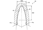
<第1の別態様>(二円弧、非対称)
図15に示すように、本態様では、V字溝の溝形状が左右非対称形状に構成されている。
つまり本態様では、左右の各溝形状は、二円弧法の手法に基づいて形成されているが、溝底部側の円弧を構成する小円CSa、CSb、溝壁部側の円弧を構成する大円CLa、CLbの各径が、左右で異なっている。
また、V字溝の溝底部は、前述の実施形態と同様に、舌部43の突端部分における両側壁41aから等距離の位置に設定されている。
なお、一方の側壁41aから他方の側壁41aにかけて、厚み寸法Tは一定に設定されている(図8、図9参照)。
このような溝形状は、たとえば片吸込型などのように、左右で流速が異なりやすい形式の遠心ポンプPMPに対して好適である。
図15に示すように、本態様では、V字溝の溝形状が左右非対称形状に構成されている。
つまり本態様では、左右の各溝形状は、二円弧法の手法に基づいて形成されているが、溝底部側の円弧を構成する小円CSa、CSb、溝壁部側の円弧を構成する大円CLa、CLbの各径が、左右で異なっている。
また、V字溝の溝底部は、前述の実施形態と同様に、舌部43の突端部分における両側壁41aから等距離の位置に設定されている。
なお、一方の側壁41aから他方の側壁41aにかけて、厚み寸法Tは一定に設定されている(図8、図9参照)。
このような溝形状は、たとえば片吸込型などのように、左右で流速が異なりやすい形式の遠心ポンプPMPに対して好適である。
<第2の別態様>(円弧+直線)
図16に示すように、本態様では、V字溝の溝形状が円弧と直線とで、左右対称形状に構成されている。
つまり本態様では、底溝部は円弧で構成され、溝壁部は直線で構成されている。
なお、一方の側壁41aから他方の側壁41aにかけて、厚み寸法Tは一定に設定されている(図8、図9参照)。
このような溝形状は、前述の実施形態のV字溝形状よりも流路断面積を小さくしたい場合に好適である。
図16に示すように、本態様では、V字溝の溝形状が円弧と直線とで、左右対称形状に構成されている。
つまり本態様では、底溝部は円弧で構成され、溝壁部は直線で構成されている。
なお、一方の側壁41aから他方の側壁41aにかけて、厚み寸法Tは一定に設定されている(図8、図9参照)。
このような溝形状は、前述の実施形態のV字溝形状よりも流路断面積を小さくしたい場合に好適である。
<第3の別態様>(三円弧)
図17に示すように、本態様では、V字溝の溝形状が三円弧法の手法に基づいて、左右対称形状に構成されている。
つまり本態様では、底溝部、溝壁部、溝開口部のそれぞれが、径の異なる3つの円(小円CS、中円CM、大円CL)によって構成され、それぞれの円弧が互いに接しつつ、連続している。
また、底溝部、溝壁部、溝開口部の順に円弧の径が大きくなるように、3つの円(小円CS、中円CM、大円CL)は、各径が設定されている。
図17に示すように、本態様では、V字溝の溝形状が三円弧法の手法に基づいて、左右対称形状に構成されている。
つまり本態様では、底溝部、溝壁部、溝開口部のそれぞれが、径の異なる3つの円(小円CS、中円CM、大円CL)によって構成され、それぞれの円弧が互いに接しつつ、連続している。
また、底溝部、溝壁部、溝開口部の順に円弧の径が大きくなるように、3つの円(小円CS、中円CM、大円CL)は、各径が設定されている。
なお、一方の側壁41aから他方の側壁41aにかけて、厚み寸法Tは一定に設定されている(図8、図9参照)。
このような溝形状は、前述の実施形態の整流突起45よりも溝壁部形状をより細かく設定したい場合、整流突起45を側壁41aから突出する部位をより滑らかに連続させたい場合、などに好適である。
このような溝形状は、前述の実施形態の整流突起45よりも溝壁部形状をより細かく設定したい場合、整流突起45を側壁41aから突出する部位をより滑らかに連続させたい場合、などに好適である。
<第4の別態様>(楕円)
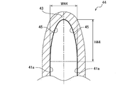
図18に示すように、本態様では、V字溝の溝形状が楕円を用いて、左右対称に構成されている。
つまり本態様では、溝形状が1つの数式で表されている。
なお、一方の側壁41aから他方の側壁41aにかけて、厚み寸法Tは一定に設定されている(図8、図9参照)。
このような溝形状は、前述の実施形態のV字溝形状よりも流路断面積を小さくしたい場合、溝壁部形状をより滑らかに連続させたい場合、溝開口部と側壁41aとをより滑らかに連続させたい場合、などに好適である。
図18に示すように、本態様では、V字溝の溝形状が楕円を用いて、左右対称に構成されている。
つまり本態様では、溝形状が1つの数式で表されている。
なお、一方の側壁41aから他方の側壁41aにかけて、厚み寸法Tは一定に設定されている(図8、図9参照)。
このような溝形状は、前述の実施形態のV字溝形状よりも流路断面積を小さくしたい場合、溝壁部形状をより滑らかに連続させたい場合、溝開口部と側壁41aとをより滑らかに連続させたい場合、などに好適である。
<第5の別態様>(二次曲線)
図19に示すように、本態様では、V字溝の溝形状が二次曲線を用いて、左右対称に構成されている。
つまり本態様では、溝形状が1つの数式で表されている。
なお、一方の側壁41aから他方の側壁41aにかけて、厚み寸法Tは一定に設定されている(図8、図9参照)。
このような溝形状は、前述の実施形態のV字溝形状よりも流路断面積を小さくしたい場合、溝壁部形状をより滑らかに連続させたい場合などに好適である。
図19に示すように、本態様では、V字溝の溝形状が二次曲線を用いて、左右対称に構成されている。
つまり本態様では、溝形状が1つの数式で表されている。
なお、一方の側壁41aから他方の側壁41aにかけて、厚み寸法Tは一定に設定されている(図8、図9参照)。
このような溝形状は、前述の実施形態のV字溝形状よりも流路断面積を小さくしたい場合、溝壁部形状をより滑らかに連続させたい場合などに好適である。
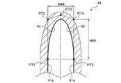
<第6の別態様>(ベジェ曲線)
図20に示すように、本態様では、V字溝の溝形状がベジェ曲線(スプライン曲線)を用いて、左右対称形状に構成されている。
ベジェ曲線は、コンピュータ上で曲線を描くために用いられる数式で、設定された複数の定義点PTをもとに曲線を表現する。
図20に示すように、本態様では、V字溝の溝形状がベジェ曲線(スプライン曲線)を用いて、左右対称形状に構成されている。
ベジェ曲線は、コンピュータ上で曲線を描くために用いられる数式で、設定された複数の定義点PTをもとに曲線を表現する。
つまり本態様では、溝開口部の定義点PT1、PT5を曲線の始点と終点に指定し、残りの定義点PT2~PT4(方向点)で溝形状を規定している。
なお、一方の側壁41aから他方の側壁41aにかけて、厚み寸法Tは一定に設定されている(図8、図9参照)。
このような溝形状は、前述の実施形態のV字溝形状とは異なる任意の形状に設定したい場合、溝壁部と側壁41aとをより滑らかに連続させたい場合、などに好適である。
なお、一方の側壁41aから他方の側壁41aにかけて、厚み寸法Tは一定に設定されている(図8、図9参照)。
このような溝形状は、前述の実施形態のV字溝形状とは異なる任意の形状に設定したい場合、溝壁部と側壁41aとをより滑らかに連続させたい場合、などに好適である。
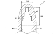
<第7の別態様>(階段)
図21に示すように、本態様では、V字溝の溝形状が階段状に、且つ左右対称形状に構成されている。
つまり本態様では、溝壁部、溝底部が階段状に構成されている。
なお、一方の側壁41aから他方の側壁41aにかけて、厚み寸法Tは一定に設定されている(図8、図9参照)。
このような溝形状は、遠心ポンプPMPの容量が比較的大きい、ケーシング30の寸法が比較的大きいなど、V字溝形状を滑らかに連続させる加工が困難な場合などに好適である。
図21に示すように、本態様では、V字溝の溝形状が階段状に、且つ左右対称形状に構成されている。
つまり本態様では、溝壁部、溝底部が階段状に構成されている。
なお、一方の側壁41aから他方の側壁41aにかけて、厚み寸法Tは一定に設定されている(図8、図9参照)。
このような溝形状は、遠心ポンプPMPの容量が比較的大きい、ケーシング30の寸法が比較的大きいなど、V字溝形状を滑らかに連続させる加工が困難な場合などに好適である。
<第8の別態様>(正規分布曲線)
図22に示すように、本態様では、V字溝の溝形状が正規分布曲線を用いて、左右対称に構成されている。
つまり本態様では、溝形状が1つの数式で表されている。
なお、一方の側壁41aから他方の側壁41aにかけて、厚み寸法Tは一定に設定されている(図8、図9参照)。
このような溝形状は、前述の実施形態のV字溝形状よりも流路断面積を小さくしたい場合などに好適である。
図22に示すように、本態様では、V字溝の溝形状が正規分布曲線を用いて、左右対称に構成されている。
つまり本態様では、溝形状が1つの数式で表されている。
なお、一方の側壁41aから他方の側壁41aにかけて、厚み寸法Tは一定に設定されている(図8、図9参照)。
このような溝形状は、前述の実施形態のV字溝形状よりも流路断面積を小さくしたい場合などに好適である。
以上、本発明の実施形態として、いわゆる両吸込単弾渦巻ポンプに適用した場合について説明したが、本願発明が適用可能な遠心式流体機械を、これに限定するものではない。
たとえば、回転軸の軸線方向片側から作動流体を吸い込む片吸込ポンプ、多段ポンプ、ラインポンプなどの縦型ポンプ、電動モータMの回転速度が変更可能な可変速運転ポンプなどへの採用が可能である。さらに、作動流体の勢いで羽根車を回転させて、発電機を駆動するポンプ水車などへの採用が可能である。
たとえば、回転軸の軸線方向片側から作動流体を吸い込む片吸込ポンプ、多段ポンプ、ラインポンプなどの縦型ポンプ、電動モータMの回転速度が変更可能な可変速運転ポンプなどへの採用が可能である。さらに、作動流体の勢いで羽根車を回転させて、発電機を駆動するポンプ水車などへの採用が可能である。
また、本発明の実施形態では、作動流体として、水などの液相流体を採用したが、これに限定するものではない。
たとえば、空気などの気相流体を作動流体として、採用することが可能である。
つまり、巻始め側37aと巻終わり側37bとが、連通部44を介して通じる渦巻流路37を備えた遠心式流体機械であれば、本願発明を採用することが可能であり、本実施形態と同様の作用効果を得ることができる。
たとえば、空気などの気相流体を作動流体として、採用することが可能である。
つまり、巻始め側37aと巻終わり側37bとが、連通部44を介して通じる渦巻流路37を備えた遠心式流体機械であれば、本願発明を採用することが可能であり、本実施形態と同様の作用効果を得ることができる。
PMP 遠心式流体機械(遠心ポンプ)
10 回転軸
20 羽根車
30 ケーシング
31 ケース本体
37 渦巻流路
37a 巻始め側
37b 巻終わり側
41a 側壁
41b 周壁
43 舌部
44 連通部
R 巻き方向
H44 溝深さ寸法
W44 側壁間寸法
T 厚み寸法
10 回転軸
20 羽根車
30 ケーシング
31 ケース本体
37 渦巻流路
37a 巻始め側
37b 巻終わり側
41a 側壁
41b 周壁
43 舌部
44 連通部
R 巻き方向
H44 溝深さ寸法
W44 側壁間寸法
T 厚み寸法
Claims (6)
- 回転軸を介して、羽根車を回転可能に軸支するケース本体と、
該羽根車の径方向外側に、該羽根車の外周に沿って、渦巻状に形成された渦巻流路と、を具備するケーシングを備え、
該渦巻流路は、
該羽根車の回転面に沿って対向配置された一対の側壁と、
該一対の側壁の径方向外側縁部を跨ぐように連結しつつ、該羽根車の外周近傍を起点とし、該羽根車の外周に沿って巻き方向へ延在しつつ、該羽根車の外周から径方向外側へ徐々に離れる渦巻形状を呈する周壁と、
該周壁の起点側端縁に、該周壁の巻き方向とは逆向きに凸の略くさび形状を有する舌部と、
該一対の側壁と該舌部とによって、巻始め側と巻終わり側とを連通する溝形状に構成された連通部と、
を備えた遠心式流体機械であって、
該連通部は、
略V字溝形状に形成された
ことを特徴とする遠心式流体機械。 - 請求項1に記載の遠心式流体機械において、
前記連通部は、
そのV字溝形状が、
溝幅寸法が、溝深さ寸法よりも小さく設定された
ことを特徴とする遠心式流体機械。 - 請求項1に記載の遠心式流体機械において、
前記連通部は、
そのV字溝形状が、
滑らかに連続する曲線で構成されている
ことを特徴とする遠心式流体機械。 - 請求項1に記載の遠心式流体機械において、
前記連通部は、
そのV字溝形状の溝底部が、
前記側壁のそれぞれから等距離の位置に設定された
ことを特徴とする遠心式流体機械。 - 請求項1に記載の遠心式流体機械において、
前記舌部は、
径方向に沿った寸法が、前記両側壁間で一定に設定された
ことを特徴とする遠心式流体機械。 - 請求項1~請求項5のいずれか1項に記載の遠心式流体機械において、
前記連通部は、
そのV字溝形状が、
前記渦巻流路の巻角度θ=0°から前記舌部の突端部分の間に設定された
ことを特徴とする遠心式流体機械。
Applications Claiming Priority (2)
| Application Number | Priority Date | Filing Date | Title |
|---|---|---|---|
| JP2019-058051 | 2019-03-26 | ||
| JP2019058051A JP7337525B2 (ja) | 2019-03-26 | 2019-03-26 | 遠心式流体機械 |
Publications (1)
| Publication Number | Publication Date |
|---|---|
| WO2020194871A1 true WO2020194871A1 (ja) | 2020-10-01 |
Family
ID=72608555
Family Applications (1)
| Application Number | Title | Priority Date | Filing Date |
|---|---|---|---|
| PCT/JP2019/046507 Ceased WO2020194871A1 (ja) | 2019-03-26 | 2019-11-28 | 遠心式流体機械 |
Country Status (3)
| Country | Link |
|---|---|
| JP (2) | JP7337525B2 (ja) |
| TW (1) | TWI730567B (ja) |
| WO (1) | WO2020194871A1 (ja) |
Families Citing this family (1)
| Publication number | Priority date | Publication date | Assignee | Title |
|---|---|---|---|---|
| JP2025142742A (ja) * | 2024-03-18 | 2025-10-01 | 川崎重工業株式会社 | 遠心ターボ機械 |
Citations (1)
| Publication number | Priority date | Publication date | Assignee | Title |
|---|---|---|---|---|
| JP2015522128A (ja) * | 2012-07-13 | 2015-08-03 | デルファイ・オートモーティブ・システムズ・ルクセンブルク・エスア | 渦巻き形状のケーシングを備えた換気デバイス |
Family Cites Families (6)
| Publication number | Priority date | Publication date | Assignee | Title |
|---|---|---|---|---|
| JP3771794B2 (ja) * | 1999-11-04 | 2006-04-26 | 三菱重工業株式会社 | 遠心ポンプ |
| JP2007120880A (ja) | 2005-10-28 | 2007-05-17 | Mitsubishi Electric Corp | クロスフローファン |
| PL2310691T3 (pl) | 2008-06-06 | 2016-11-30 | Obudowa pompy | |
| JP5338842B2 (ja) | 2011-04-04 | 2013-11-13 | 三菱電機株式会社 | クロスフローファン |
| JP6073604B2 (ja) | 2012-09-03 | 2017-02-01 | サンデンホールディングス株式会社 | 遠心送風機 |
| WO2019082392A1 (ja) * | 2017-10-27 | 2019-05-02 | 三菱電機株式会社 | 遠心送風機、送風装置、空気調和装置及び冷凍サイクル装置 |
-
2019
- 2019-03-26 JP JP2019058051A patent/JP7337525B2/ja active Active
- 2019-11-28 WO PCT/JP2019/046507 patent/WO2020194871A1/ja not_active Ceased
- 2019-12-30 TW TW108148282A patent/TWI730567B/zh active
-
2023
- 2023-07-03 JP JP2023109023A patent/JP7598976B2/ja active Active
Patent Citations (1)
| Publication number | Priority date | Publication date | Assignee | Title |
|---|---|---|---|---|
| JP2015522128A (ja) * | 2012-07-13 | 2015-08-03 | デルファイ・オートモーティブ・システムズ・ルクセンブルク・エスア | 渦巻き形状のケーシングを備えた換気デバイス |
Also Published As
| Publication number | Publication date |
|---|---|
| JP2020159256A (ja) | 2020-10-01 |
| TW202035876A (zh) | 2020-10-01 |
| JP7337525B2 (ja) | 2023-09-04 |
| JP2023121843A (ja) | 2023-08-31 |
| JP7598976B2 (ja) | 2024-12-12 |
| TWI730567B (zh) | 2021-06-11 |
Similar Documents
| Publication | Publication Date | Title |
|---|---|---|
| KR101790421B1 (ko) | 터보머신들의 인접한 블레이드 요소들의 흐름장들의 결합을 가하는 구조들 및 방법들, 그리고 그들을 포함하는 터보머신들 | |
| JP3872966B2 (ja) | 軸流形流体機械 | |
| KR101937070B1 (ko) | 터빈 | |
| US10273973B2 (en) | Centrifugal compressor having an asymmetric self-recirculating casing treatment | |
| CN107965473B (zh) | 包括具有开口的至少一个叶片的、用于流体压缩装置的扩散器 | |
| WO2017138199A1 (ja) | 遠心圧縮機 | |
| US9234526B2 (en) | Centrifugal compressor having an asymmetric self-recirculating casing treatment | |
| JP2017515042A (ja) | 羽根車、特にサイドチャネルマシーン用羽根車 | |
| TW201441489A (zh) | 流體泵浦低紊流動葉輪 | |
| EA037381B1 (ru) | Способ и устройство для уменьшения окружного дисбаланса давления в боковой полости рабочего колеса турбомашин | |
| JP3841391B2 (ja) | ターボ機械 | |
| KR20150120168A (ko) | 원심형 혼류송풍기 | |
| JP7598976B2 (ja) | 遠心式流体機械 | |
| US9897110B2 (en) | Centrifugal compressor | |
| CN113383147B (zh) | 旋转机械 | |
| JP6802770B2 (ja) | 流体機械 | |
| JP2010025041A (ja) | 遠心流体機械 | |
| JP2018091317A (ja) | 多段ポンプ | |
| JP2011137407A (ja) | 水車 | |
| JP6775379B2 (ja) | インペラ及び回転機械 | |
| JP2006170112A (ja) | 流体機械の不安定流動抑制装置 | |
| JP6740070B2 (ja) | 流体機械 | |
| JP5748505B2 (ja) | 回転機械 | |
| JP2015135095A (ja) | シール装置、及び回転機械 | |
| JP6553971B2 (ja) | 流体機械 |
Legal Events
| Date | Code | Title | Description |
|---|---|---|---|
| 121 | Ep: the epo has been informed by wipo that ep was designated in this application |
Ref document number: 19921393 Country of ref document: EP Kind code of ref document: A1 |
|
| NENP | Non-entry into the national phase |
Ref country code: DE |
|
| 122 | Ep: pct application non-entry in european phase |
Ref document number: 19921393 Country of ref document: EP Kind code of ref document: A1 |