WO2020194930A1 - Dispositif d'alimentation électrique, véhicule électrique le comportant, et dispositif de stockage d'énergie - Google Patents
Dispositif d'alimentation électrique, véhicule électrique le comportant, et dispositif de stockage d'énergie Download PDFInfo
- Publication number
- WO2020194930A1 WO2020194930A1 PCT/JP2019/049758 JP2019049758W WO2020194930A1 WO 2020194930 A1 WO2020194930 A1 WO 2020194930A1 JP 2019049758 W JP2019049758 W JP 2019049758W WO 2020194930 A1 WO2020194930 A1 WO 2020194930A1
- Authority
- WO
- WIPO (PCT)
- Prior art keywords
- power supply
- supply device
- secondary battery
- power
- spring member
- Prior art date
- Legal status (The legal status is an assumption and is not a legal conclusion. Google has not performed a legal analysis and makes no representation as to the accuracy of the status listed.)
- Ceased
Links
Images






Classifications
-
- H—ELECTRICITY
- H01—ELECTRIC ELEMENTS
- H01M—PROCESSES OR MEANS, e.g. BATTERIES, FOR THE DIRECT CONVERSION OF CHEMICAL ENERGY INTO ELECTRICAL ENERGY
- H01M50/00—Constructional details or processes of manufacture of the non-active parts of electrochemical cells other than fuel cells, e.g. hybrid cells
- H01M50/20—Mountings; Secondary casings or frames; Racks, modules or packs; Suspension devices; Shock absorbers; Transport or carrying devices; Holders
- H01M50/204—Racks, modules or packs for multiple batteries or multiple cells
- H01M50/207—Racks, modules or packs for multiple batteries or multiple cells characterised by their shape
- H01M50/209—Racks, modules or packs for multiple batteries or multiple cells characterised by their shape adapted for prismatic or rectangular cells
-
- H—ELECTRICITY
- H01—ELECTRIC ELEMENTS
- H01M—PROCESSES OR MEANS, e.g. BATTERIES, FOR THE DIRECT CONVERSION OF CHEMICAL ENERGY INTO ELECTRICAL ENERGY
- H01M50/00—Constructional details or processes of manufacture of the non-active parts of electrochemical cells other than fuel cells, e.g. hybrid cells
- H01M50/20—Mountings; Secondary casings or frames; Racks, modules or packs; Suspension devices; Shock absorbers; Transport or carrying devices; Holders
- H01M50/262—Mountings; Secondary casings or frames; Racks, modules or packs; Suspension devices; Shock absorbers; Transport or carrying devices; Holders with fastening means, e.g. locks
-
- Y—GENERAL TAGGING OF NEW TECHNOLOGICAL DEVELOPMENTS; GENERAL TAGGING OF CROSS-SECTIONAL TECHNOLOGIES SPANNING OVER SEVERAL SECTIONS OF THE IPC; TECHNICAL SUBJECTS COVERED BY FORMER USPC CROSS-REFERENCE ART COLLECTIONS [XRACs] AND DIGESTS
- Y02—TECHNOLOGIES OR APPLICATIONS FOR MITIGATION OR ADAPTATION AGAINST CLIMATE CHANGE
- Y02T—CLIMATE CHANGE MITIGATION TECHNOLOGIES RELATED TO TRANSPORTATION
- Y02T10/00—Road transport of goods or passengers
- Y02T10/60—Other road transportation technologies with climate change mitigation effect
- Y02T10/62—Hybrid vehicles
Definitions
- the present invention relates to a power supply device, an electric vehicle using the power supply device, and a power storage device.
- the power supply device is used as a power supply device for driving an electric vehicle, a power supply device for storing electricity, and the like.
- a plurality of rechargeable secondary battery cells are stacked.
- the power supply device 900 has secondary battery cells 901 of a square outer can on both end faces of a battery laminate in which insulating spacers 902 are alternately laminated.
- the end plates 903 are arranged respectively, and the end plates 903 are fastened to each other with a metal bind bar 904.
- the outer can of the secondary battery cell expands and contracts when charging and discharging are repeated.
- the capacity of each secondary battery cell is increasing, and as a result, the amount of expansion tends to increase.
- the amount of expansion also increases according to the number of secondary battery cells.
- the load on the bind bar increases.
- the bind bar is made of a high-strength metal plate, the elastic modulus is low in the case of metal, so the restoring force is weak. That is, even if the metal bind bar is stretched and deformed when the secondary battery cell expands, the bind bar does not return to its original shape when the secondary battery cell contracts. There is a problem that the fastening force of the battery laminate by the bar is reduced and the position is displaced due to impact or vibration.
- One of the objects of the present invention is to provide a power supply device having improved followability to deformation such as expansion and contraction of a secondary battery cell, an electric vehicle using the power supply device, and a power storage device.
- the power supply device includes a plurality of secondary battery cells having a square outer can, a pair of end plates covering both end faces of a battery laminate in which the plurality of secondary battery cells are laminated, and the like. It has a plate shape extending along the stacking direction of the plurality of secondary battery cells, and is provided with a plurality of fastening members arranged on opposite side surfaces of the battery stack and fastening the end plates to each other. .. Further, a space is formed in the intermediate portion of the battery laminate in the stacking direction. The space is provided with a spring member urged to press the stacking direction of the battery laminate.
- the fastening state can be maintained by the spring member while absorbing the deformation of the stacking direction length of the battery laminate by the space provided in the stacking direction of the secondary battery cells.
- FIG. It is a perspective view which shows the power supply device which concerns on Embodiment 1.
- FIG. It is an exploded perspective view of the power supply device of FIG. It is a top view of the power supply device of FIG. It is a horizontal sectional view of the power supply device of FIG. 1 in line IV-IV.
- FIG. 5 is a vertical cross-sectional view taken along the line VV of the power supply device of FIG.
- It is an exploded perspective view of the fastening member of FIG.
- It is a perspective view of a spring member.
- FIG. It is a horizontal sectional view of the power supply device which concerns on Embodiment 2.
- FIG. It is a perspective view which shows the state which the spring member was contracted. It is a perspective view which shows the state which stretched the spring member.
- FIG. 3 is a perspective view showing a spring member of the power supply device according to the third embodiment. It is a perspective view which shows the spring member of the power supply device which concerns on Embodiment 4.
- FIG. It is a perspective view which shows the spring member of the power supply device which concerns on Embodiment 5.
- Embodiment 6 It is a perspective view of the power supply device which concerns on Embodiment 7.
- Embodiment 7 It is an exploded perspective view of the power supply device which concerns on a comparative example.
- the embodiment of the present invention may be specified by the following configuration.
- the power supply device further includes pressing plates for fixing the spring member on both sides of the spring member.
- the pressing plate is a resin member in which the spring member is insert-molded.
- the spring member is fixed to the center of the pressing plate.
- the space is arranged at the center in the stacking direction of the battery laminate.
- the spring member is a coil spring.
- the spring member is a leaf spring.
- the power supply device is provided with a plurality of the spring members.
- the electric vehicle includes any of the above power supply devices, a traveling motor to which power is supplied from the power supply device, the power supply device, and the motor. It includes a main body and wheels driven by the motor to drive the vehicle main body.
- the power storage device includes any of the above power supply devices and a power supply controller that controls charging / discharging to the power supply device, and the power supply controller provides power from the outside. Allows the secondary battery cell to be charged and controls the secondary battery cell to be charged.
- each element constituting the present invention may be configured such that a plurality of elements are composed of the same member and the plurality of elements are combined with one member, or conversely, the function of one member is performed by the plurality of members. It can also be shared and realized.
- the contents described in some examples and embodiments can be used in other embodiments and embodiments.
- the power supply device is a power source mounted on an electric vehicle such as a hybrid vehicle or an electric vehicle to supply electric power to a traveling motor, a power source for storing natural energy generated power such as solar power generation or wind power generation, or a power source for storing electric power generated by natural energy such as solar power generation and wind power generation. It is used for various purposes such as a power source for storing midnight power, and is particularly suitable as a power source suitable for high power and large current applications.
- an embodiment applied to a power supply device for driving an electric vehicle will be described.
- FIGS. 1 to 5 The power supply device 100 according to the first embodiment of the present invention is shown in FIGS. 1 to 5, respectively.
- FIG. 1 is a perspective view showing a power supply device 100 according to the first embodiment
- FIG. 2 is an exploded perspective view of the power supply device 100 of FIG. 1
- FIG. 3 is a plan view of the power supply device 100 of FIG. 1 is a horizontal sectional view of the power supply device 100 of FIG. 1 on the IV-IV line
- FIG. 5 is a vertical sectional view of the power supply device 100 of FIG. 1 on the VV line.
- the power supply device 100 shown in these figures fastens a battery laminate 10 in which a plurality of secondary battery cells 1 are laminated, a pair of end plates 20 covering both end faces of the battery laminate 10, and end plates 20 to each other.
- a plurality of fastening members 15 and an insulating insulating sheet 30 interposed between each of the plurality of fastening members 15 and the battery laminate 10 are provided. (Battery laminate 10)
- the battery laminate 10 is connected to a plurality of secondary battery cells 1 having positive and negative electrode terminals 2 and electrode terminals 2 of the plurality of secondary battery cells 1.
- a bus bar (not shown) for connecting a plurality of secondary battery cells 1 in parallel and in series is provided.
- a plurality of secondary battery cells 1 are connected in parallel or in series via these bus bars.
- the secondary battery cell 1 is a rechargeable secondary battery.
- a plurality of secondary battery cells 1 are connected in parallel to form a parallel battery group, and a plurality of parallel battery groups are connected in series so that a large number of secondary battery cells 1 are connected in parallel and in series. Be connected.
- a plurality of secondary battery cells 1 are laminated to form a battery laminate 10. Further, a pair of end plates 20 are arranged on both end faces of the battery laminate 10. The ends of the fastening members 15 are fixed to the end plates 20, and the laminated secondary battery cells 1 are fixed in a pressed state. (Secondary battery cell 1)
- the secondary battery cell 1 is a square battery having a quadrangular outer shape of a main surface having a wide surface and a CD having a constant cell thickness, and the thickness is thinner than the width. Further, the secondary battery cell 1 is a secondary battery that can be charged and discharged, and is a lithium ion secondary battery. However, the present invention does not specify the secondary battery cell as a square battery, nor does it specify a lithium ion secondary battery. As the secondary battery cell, all rechargeable batteries, for example, a non-aqueous electrolyte secondary battery other than the lithium ion secondary battery, a nickel hydrogen secondary battery cell, and the like can also be used.
- an electrode body in which positive and negative electrode plates are laminated is housed in an outer can 1a, filled with an electrolytic solution, and airtightly sealed.
- the outer can 1a is formed into a square tubular shape that closes the bottom, and the opening above the outer can 1a is hermetically closed by a metal plate sealing plate 1b.
- the outer can 1a is manufactured by deep drawing a metal plate such as aluminum or an aluminum alloy.
- the sealing plate 1b is made of a metal plate such as aluminum or an aluminum alloy, like the outer can 1a.
- the sealing plate 1b is inserted into the opening of the outer can 1a, irradiates the boundary between the outer periphery of the sealing plate 1b and the inner circumference of the outer can 1a with a laser beam, and the sealing plate 1b is laser welded to the outer can 1a. It is fixed airtightly. (Electrode terminal 2)
- the secondary battery cell 1 has a sealing plate 1b, which is the top surface, as a terminal surface 1X, and positive and negative electrode terminals 2 are fixed to both ends of the terminal surface 1X.
- the electrode terminal 2 has a columnar protrusion.
- the protruding portion does not necessarily have to be cylindrical, and may be polygonal or elliptical.
- the positions of the positive and negative electrode terminals 2 fixed to the sealing plate 1b of the secondary battery cell 1 are such that the positive electrode and the negative electrode are symmetrical.
- the secondary battery cells 1 are vertically inverted and stacked, and the electrode terminals 2 of the positive electrode and the negative electrode that are adjacent to each other are connected by a bus bar to form two adjacent batteries.
- the next battery cells 1 can be connected in series.
- the present invention does not specify the number of secondary battery cells constituting the battery laminate and the connection state thereof.
- the number of secondary battery cells constituting the battery laminate and the connection state thereof can be variously changed, including other embodiments described later. (Battery laminate 10)
- the plurality of secondary battery cells 1 are laminated so that the thickness direction of each secondary battery cell 1 is the stacking direction to form the battery laminate 10.
- a plurality of secondary battery cells 1 are laminated so that the terminal surface 1X provided with the positive and negative electrode terminals 2 and the sealing plate 1b in FIGS. 1 to 2 are flush with each other.
- the battery laminate 10 may have an insulating spacer 16 interposed between the secondary battery cells 1 stacked adjacent to each other.
- the insulating spacer 16 is made of an insulating material such as resin in the form of a thin plate or sheet.
- the insulating spacer 16 has a plate shape having a size substantially equal to the facing surface of the secondary battery cell 1.
- the insulating spacers 16 can be laminated between the secondary battery cells 1 adjacent to each other to insulate the adjacent secondary battery cells 1 from each other.
- a spacer having a shape in which a flow path of a cooling gas is formed between the secondary battery cell and the spacer can also be used.
- the surface of the secondary battery cell can be coated with an insulating material.
- the surface of the outer can excluding the electrode portion of the secondary battery cell may be heat-welded with a shrink tube made of PET resin or the like.
- the insulating spacer may be omitted.
- the secondary battery cells connected in series are insulated by interposing an insulating spacer between the secondary battery cells, while being connected in parallel with each other. Since there is no voltage difference between the adjacent outer cans of the secondary battery cells, the insulating spacer between the secondary battery cells can be omitted.
- end plates 20 are arranged on both end surfaces of the battery laminate 10.
- An end face spacer 17 may be interposed between the end plate 20 and the battery laminate 10 to insulate them.
- the end face spacer 17 can also be manufactured in the form of a thin plate or sheet with an insulating material such as resin.
- the electrode terminals 2 of the plurality of secondary battery cells 1 adjacent to each other are connected by a bus bar.
- a plurality of secondary battery cells 1 are connected in parallel and in series.
- the bus bar holder may be arranged between the battery laminate 10 and the bus bar.
- the bus bar is manufactured into a predetermined shape by cutting and processing a metal plate.
- a metal plate constituting the bus bar a metal having low electric resistance and light weight, for example, an aluminum plate or a copper plate, or an alloy thereof can be used.
- other metals with low electrical resistance and light weight and alloys thereof can also be used.
- the end plates 20 are arranged at both ends of the battery laminate 10 and are fastened via a pair of left and right fastening members 15 arranged along both side surfaces of the battery laminate 10. Will be done.
- the end plates 20 are both ends of the secondary battery cell 1 of the battery laminate 10 in the stacking direction, and are arranged outside the end face spacer 17 to sandwich the battery laminate 10 from both ends.
- the end plate 20 forms a stepped portion 20b for locking the locking block 15b provided on the fastening member 15 in a state of being fastened by the fastening member 15.
- the step portion 20b is formed in a size and shape capable of locking the locking block 15b of the fastening member 15 described later.
- a brim-shaped step portion 20b is formed so that the end plate 20 has a T-shape in a horizontal cross-sectional view.
- an end plate screw hole 20c is opened in the vicinity of the step portion 20b.
- each fastening member 15 is made of metal having a predetermined width and a predetermined thickness along the side surface of the battery laminate 10 and faces both side surfaces of the battery laminate 10. Have been placed.
- a metal plate such as iron, preferably a steel plate, can be used for the fastening member 15.
- the fastening member 15 made of a metal plate is bent by press forming or the like to form a predetermined shape.
- the fastening member 15 includes a fastening main surface 15a and a block-shaped locking block 15b.
- the fastening main surface 15a is a plate-shaped member, which is bent in a U-shape at the top and bottom to form a bent piece 15d.
- the upper and lower bent pieces 15d cover the upper and lower surfaces of the battery laminate 10 from the corners on the left and right side surfaces of the battery laminate 10.
- the locking block 15b is fixed to both sides of the fastening main surface 15a.
- the locking block 15b has a plate shape having a predetermined thickness, and is fixed in a posture of projecting inward of the fastening main surface 15a. With the fastening member 15 connected to the end plate 20, the locking block 15b is locked to the stepped portion 20b provided on the end plate 20, and the fastening member 15 is arranged at a fixed position on both sides of the battery laminate 10.
- the locking block 15b is fixed to the fastening main surface 15a by welding such as spot welding or laser welding.
- This locking block 15b has a fastening side through hole 15bc opened so as to coincide with the end plate screw hole 20c in a state where the end plate 20 is fastened. Further, the fastening main surface 15a has a fastening main surface side through hole 15ac opened at a position corresponding to the fastening side through hole 15bc. The fastening side through hole 15bc and the fastening main surface side through hole 15ac are designed to match with the locking block 15b fixed to the fastening main surface 15a.
- a plurality of fastening side through holes 15bc opened in the locking block 15b are arranged along the extension direction of the locking block 15b.
- a plurality of through holes 15ac on the fastening main surface side are opened along the edge of the fastening main surface 15a or the extension direction of the locking block 15b.
- a plurality of end plate screw holes 20c are also formed along the side surface of the end plate 20 accordingly.
- the locking block 15b is fixed to the outer peripheral surface of the end plate 20 via a plurality of bolts 15f.
- the fastening of the fastening main surface 15a, the locking block 15b, and the end plate 20 is not necessarily limited to screwing with bolts, and may be pins, rivets, or the like.
- the fastening main surface 15a and the locking block 15b can be made of iron, iron alloy, SUS, aluminum, aluminum alloy, or the like. Further, the locking block 15b can have a width of 10 mm or more in the battery stacking direction. Furthermore, the end plate 20 can be made of metal. Preferably, the locking block 15b and the fastening main surface 15a are made of the same metal. As a result, the locking block 15b and the fastening main surface 15a can be easily welded.
- the fastening member 15 is not bent at the left and right ends in the longitudinal direction, that is, in the direction of the laminated layer of the battery laminate 10 and screwed from the main surface side of the end plate 20, but is shown in FIGS. 1 to 4.
- the fastening member 15 has a flat plate shape in the stacking direction of the battery laminate 10, and has a locking structure and a screw by the locking block 15b and the stepped portion 20b without providing a bent portion for locking to the end plate 20.
- a plurality of power supply devices 100 in which a large number of secondary battery cells 1 are laminated are formed by connecting end plates 20 arranged at both ends of a battery laminate 10 composed of the plurality of secondary battery cells 1 with fastening members 15. It is configured to restrain the secondary battery cell 1 of the above. By restraining the plurality of secondary battery cells 1 via the end plate 20 and the fastening member 15 having high rigidity, the secondary battery cells 1 malfunction due to expansion, deformation, relative movement, and vibration due to charge / discharge and deterioration. Etc. can be suppressed. (Insulation sheet 30)
- an insulating sheet 30 is interposed between the fastening member 15 and the battery laminate 10.
- the insulating sheet 30 is made of a material having an insulating property, for example, resin, and insulates between the metal fastening member 15 and the battery cell.
- the insulating sheet 30 shown in FIG. 2 and the like is composed of a flat plate 31 that covers the side surface of the battery laminate 10 and bent covering portions 32 provided above and below the flat plate 31.
- the bent covering portion 32 is bent in a U shape from the flat plate 31 so as to cover the bent piece 15d of the fastening member 15, and then further folded back.
- the bent piece 15d can be covered with an insulating bent covering portion from the upper surface to the side surface and the lower surface, thereby avoiding unintended conduction between the secondary battery cell 1 and the fastening member 15.
- the bent piece 15d presses the upper surface and the lower surface of the secondary battery cell 1 of the battery laminate 10 via the bent covering portion. As a result, each secondary battery cell 1 is pressed by the bent piece 15d from the vertical direction and held in the height direction, and even if vibration, impact, or the like is applied to the battery laminate 10, each secondary battery cell 1 is pressed. It can be maintained so that it does not shift in the vertical direction.
- the surface of the battery laminate or the battery laminate is insulated, for example, when the secondary battery cell is housed in an insulating case, covered with a resin heat-shrinkable tube, or fastened.
- the insulating sheet can be eliminated when the surface of the member is coated with an insulating paint or coating, or when the fastening member is made of an insulating material.
- the bent covering portion may be formed only on the upper end side.
- the insulating sheet may be configured to also serve as a bus bar holder for holding the bus bar described above. (Space SP)
- a space SP is formed in the intermediate portion of the battery laminate in the stacking direction.
- the space SP is preferably arranged at the center of the battery laminate 10 in the stacking direction. By doing so, the changes in the battery laminate 10 can be collectively absorbed at one central location, and the displacement of the battery laminate 10 can be suppressed. For example, the amount of movement of the total terminals of the battery laminate 10 can be suppressed, and the load applied to the fixed portion of the total terminals due to the movement can be reduced.
- a space SP is arranged between the 5 secondary battery cells 1 and the 6 secondary battery cells 1.
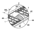
- a spring member 40 is arranged in this space SP.
- a configuration example of the spring member 40 is shown in the perspective view of FIG.
- the spring member 40 shown in this figure is provided with pressing plates 42 on both sides thereof.
- the spring member 40 is urged to press the battery laminate 10 in the stacking direction of the secondary battery cell 1. With such a configuration, the spring member 40 can maintain the fastened state of the secondary battery cell 1 while absorbing the displacement at the time of expansion in the space SP provided in the stacking direction.
- the spring member 40 is fixed to the center of the main surface of the pressing plate 42. (Press plate 42)
- Each of the pressing plates 42 is formed to have substantially the same size as the side surface of the outer can of the secondary battery cell 1.
- the pressing plate 42 disperses the stress transmitted from the spring member 40 and uniformly presses the side surface of the secondary battery cell 1.
- the pressing plate 42 is made of a material having sufficient strength. It is preferably composed of a resin material having an insulating property. As a result, insulation can be ensured when a metal spring is used for the spring member 40.
- the pressing plate 42 of FIG. 7 forms a spring holding portion 44 for fixing the spring member 40.
- the spring holding portion 44 is formed in a tubular shape having an outer diameter larger than the outer diameter of the coil spring, and fixes the periphery of the coil spring.
- the pressing plate 42 is a resin member in which both sides of the spring member 40 are insert-molded by the spring holding portion 44. As a result, the spring member 40 can be stably fixed to the pressing plate 42.
- the thickness of the spring holding portion 44 is designed in consideration of the expansion amount of the battery laminate 10 in the space SP and the fixing strength of the spring member 40.
- the thickness of the spring holding portion 44 is adjusted to, for example, 1 mm to 50 mm.
- the pressing plate 42 may be made of a metal plate. In this case, since it is necessary to insulate the battery laminate 10, for example, an insulating member is interposed between the pressing plate 42 and the end face of the battery laminate 10. (Stopper 46)
- the two pressing plates 42 are separated in parallel via a spring member 40. Further, a stopper 46 may be provided between the pressing plates 42.
- the stopper 46 defines a minimum value at which the widths of the pressing plates 42 do not become shorter than this.
- the stoppers 46 are fixed to the corners of one of the pressing plates 42, respectively.
- Each stopper 46 is projected in a rod shape, and the tip thereof is a flat surface.
- the length WP of the stopper 46 is defined as the minimum width of the space SP, and the spring member 40 can be protected from exceeding the lower limit of the compressed state.
- the pressing force can be exerted with equal surface pressure on both sides of the spring member 40, and the spring member 40 arranged in the middle of the battery laminate 10 can be used.
- the pressed state can be maintained while absorbing the amount of deformation. That is, as shown in the perspective view of FIG. 9, when the secondary battery cell 1 is expanded, the spring member in the space SP absorbs the deformation in which the battery laminate 10 becomes long due to the narrowing of the width W1 of the space SP.
- the 40 keeps the fastened state by pressing the left and right sides in the middle of the battery laminate 10 via the pressing plate 42.
- the spring member 40 moves left and right in the middle of the battery laminate 10 so that the width W2 of the space SP becomes large. By pressing, the fastened state of the battery laminate 10 can be maintained.
- the spring member 40 is preferably made of a metal member. In the example of FIG. 7, it is a coil spring. However, the spring member 40 is not limited to the coil spring, and other elastic bodies can be appropriately used.
- the elastic body may be composed of a leaf spring.
- the elastic body of the leaf spring is formed by bending the leaf spring, which is the spring member 40B, into a chevron shape and interposing it in the middle of the battery laminate 10 with the pressing plate 42, as in the power supply device 300 according to the third embodiment shown in FIG. It is a mode to make it.
- the spring member 40C which is curved outward from the pressing plate 42 may be used.
- the spring member 40D may be composed of a disc spring as in the power supply device according to the fifth embodiment shown in FIG.
- the number of stacked secondary battery cells 1 can be adjusted arbitrarily.
- the spring member 40 may be provided in the middle of the battery laminate 10 in which a large number of secondary battery cells 1 (36 in this case) are laminated.
- multiple power supplies may be used in combination.
- a plurality of power supply devices in which a fixed number of secondary battery cells are stacked are connected in series or in parallel to achieve higher output and higher capacity. ..
- the total length of the power supply device is increased by the amount of the space provided.
- the number of spaces is accumulated by the number of power supply devices, and the entire device becomes large.
- the power supply device 800 in which the spring member 40 is arranged between the end face of the battery laminate 10 and the end plate 20 such a power supply device 800 is used in series, that is, secondary. If the battery cells 1 are arranged in a straight line in the stacking direction, the entire device becomes longer by the number of space SPs. Therefore, as shown in FIG.
- the space SP is provided not at the end face of the secondary battery cell 1 but in the middle, and the intermediate end plate is also omitted so that all the secondary battery cells 1 are integrally laminated.
- the power supply device 100 described above restrains the plurality of secondary battery cells 1 by connecting the end plates 20 arranged at both ends of the battery laminate 10 in which the plurality of secondary battery cells 1 are laminated by fastening members 15. ..
- the secondary battery cells 1 malfunction due to expansion, deformation, relative movement, and vibration due to charge / discharge and deterioration. Etc. can be suppressed.
- the secondary battery cell 1 is provided by the spring member 40. By urging in the direction of fastening the batteries, rattling due to the provision of the space SP can be suppressed, and the deformation of the secondary battery cell 1 can be allowed while being stably held.
- the stress that tends to spread in the battery stacking direction caused by the expansion of the secondary battery cell 1 is locked to the stepped portion 20b in addition to the fastening portion itself. It is applied to each member of engagement by the block 15b, welding of the fastening portion and the locking block 15b, and screwing by the bolt 15f. Therefore, by increasing the rigidity of each of these members and appropriately dispersing the stress, it is possible to realize the power supply device 100 capable of increasing the rigidity as a whole and responding to the expansion and contraction of the secondary battery cell 1.
- the above power supply device 100 can be used as a power source for a vehicle that supplies electric power to a motor that runs an electric vehicle.
- an electric vehicle such as a hybrid vehicle or a plug-in hybrid vehicle that runs on both an engine and a motor, or an electric vehicle that runs only on a motor can be used, and is used as a power source for these vehicles. Will be done.
- a large number of the above-mentioned power supply devices 100 are connected in series or in parallel, and a large-capacity, high-output power supply device to which a necessary control circuit is added is constructed. To do. (Power supply for hybrid vehicles)
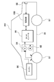
- FIG. 17 shows an example in which the power supply device 100 is mounted on a hybrid vehicle that runs on both an engine and a motor.
- the vehicle HV equipped with the power supply device 100 shown in this figure is driven by a vehicle body 91, an engine 96 for traveling the vehicle body 91, a motor 93 for traveling, and these engines 96 and a motor 93 for traveling. It includes wheels 97, a power supply device 100 that supplies electric power to the motor 93, and a generator 94 that charges the batteries of the power supply device 100.
- the power supply device 100 is connected to the motor 93 and the generator 94 via the DC / AC inverter 95.
- the vehicle HV runs on both the motor 93 and the engine 96 while charging and discharging the battery of the power supply device 100.
- the motor 93 is driven to drive the vehicle in a region where the engine efficiency is low, for example, when accelerating or traveling at a low speed.
- the motor 93 is driven by being supplied with electric power from the power supply device 100.
- the generator 94 is driven by the engine 96 or by regenerative braking when braking the vehicle to charge the battery of the power supply device 100.
- the vehicle HV may include a charging plug 98 for charging the power supply device 100. By connecting the charging plug 98 to an external power source, the power supply device 100 can be charged. (Power supply for electric vehicles)
- FIG. 18 shows an example in which the power supply device 100 is mounted on an electric vehicle traveling only by a motor.
- the vehicle EV equipped with the power supply device 100 shown in this figure supplies electric power to the vehicle body 91, the traveling motor 93 for running the vehicle body 91, the wheels 97 driven by the motor 93, and the motor 93. It includes a power supply device 100 for supplying power and a generator 94 for charging the battery of the power supply device 100.
- the power supply device 100 is connected to the motor 93 and the generator 94 via the DC / AC inverter 95.
- the motor 93 is driven by being supplied with electric power from the power supply device 100.
- the generator 94 is driven by the energy used for regenerative braking of the vehicle EV to charge the battery of the power supply device 100.
- the vehicle EV is provided with a charging plug 98, and the charging plug 98 can be connected to an external power source to charge the power supply device 100. (Power supply device for power storage device)
- the present invention does not specify the use of the power supply device as the power supply of the motor that runs the vehicle.
- the power supply device according to the embodiment can also be used as a power source for a power storage device that charges and stores a battery with electric power generated by solar power generation, wind power generation, or the like.
- FIG. 19 shows a power storage device in which the battery of the power supply device 100 is charged by the solar cell 82 to store electricity.
- the power storage device shown in FIG. 19 charges the battery of the power supply device 100 with the electric power generated by the solar cell 82 arranged on the roof or roof of a building 81 such as a house or factory.
- This power storage device uses the solar cell 82 as a power source for charging, charges the battery of the power supply device 100 with the charging circuit 83, and then supplies power to the load 86 via the DC / AC inverter 85. Therefore, this power storage device has a charge mode and a discharge mode.
- the DC / AC inverter 85 and the charging circuit 83 are connected to the power supply device 100 via the discharge switch 87 and the charging switch 84, respectively.
- the ON / OFF of the discharge switch 87 and the charge switch 84 is switched by the power controller 88 of the power storage device.
- the power controller 88 switches the charging switch 84 to ON and the discharge switch 87 to OFF to allow the charging circuit 83 to charge the power supply device 100.
- the power controller 88 turns off the charging switch 84 and turns on the discharge switch 87 to switch to the discharge mode, and the power supply device 100 Allows discharge from to load 86.
- the charge switch 84 can be turned on and the discharge switch 87 can be turned on to supply power to the load 86 and charge the power supply device 100 at the same time.
- the power supply device can also be used as a power source for a power storage device that charges and stores batteries by using midnight power at night.
- a power supply device charged with midnight power can be charged with midnight power, which is surplus power of a power plant, and output power in the daytime when the power load is large, so that the peak power in the daytime can be limited to a small value.
- the power supply can also be used as a power source for charging with both solar cell output and midnight power. This power supply device can effectively utilize both the power generated by the solar cell and the midnight power, and can efficiently store electricity while considering the weather and power consumption.
- the above-mentioned power storage system includes a backup power supply device that can be mounted in a computer server rack, a backup power supply device for a wireless base station such as a mobile phone, a power storage power supply for home or factory use, a power supply for street lights, etc. It can be suitably used for power storage devices combined with solar cells, backup power sources for traffic lights and road traffic indicators, and the like.
- the power supply device according to the present invention and a vehicle provided with the power supply device are suitably used as a power source for a large current used for a power source of a motor for driving an electric vehicle such as a hybrid vehicle, a fuel cell vehicle, an electric vehicle, or an electric motorcycle.
- a power supply device for a plug-in hybrid electric vehicle, a hybrid electric vehicle, an electric vehicle, or the like that can switch between an EV driving mode and a HEV driving mode can be mentioned.
- a backup power supply device that can be mounted on a computer server rack, a backup power supply device for wireless base stations such as mobile phones, a power storage device for home use and factories, a power supply for street lights, etc. , Can also be used as appropriate for backup power supplies such as traffic lights.
Landscapes
- Chemical & Material Sciences (AREA)
- Chemical Kinetics & Catalysis (AREA)
- Electrochemistry (AREA)
- General Chemical & Material Sciences (AREA)
- Battery Mounting, Suspending (AREA)
Abstract
La présente invention concerne, afin de fournir un dispositif d'alimentation électrique ayant une aptitude à la déformation améliorée telle que la dilatation et la contraction d'une cellule de batterie secondaire, un véhicule électrique l'utilisant, et un dispositif de stockage d'énergie, un dispositif d'alimentation électrique (100) comprend : une pluralité de cellules de batterie secondaires (1) ayant une boîte externe rectangulaire ; une paire de plaques d'extrémité (20) qui couvrent les deux surfaces d'extrémité d'un empilement de batteries (10) dans lequel la pluralité de cellules de batterie secondaires (1) sont empilées ; et une pluralité d'éléments de fixation (15) qui sont formés sous une forme de plaque s'étendant le long d'une direction d'empilement de la pluralité de cellules de batterie secondaires (1) et sont respectivement agencés sur des surfaces latérales opposées de l'empilement de batteries (10) pour fixer les plaques d'extrémité (20) l'une à l'autre. En outre, un espace est formé dans une partie intermédiaire de l'empilement de batteries (10) dans la direction d'empilement. Un élément de ressort (40) sollicité pour presser l'empilement de batteries (10) dans la direction d'empilement est disposé dans l'espace.
Applications Claiming Priority (2)
| Application Number | Priority Date | Filing Date | Title |
|---|---|---|---|
| JP2019062920A JP2022078378A (ja) | 2019-03-28 | 2019-03-28 | 電源装置及びこれを用いた電動車両並びに蓄電装置 |
| JP2019-062920 | 2019-03-28 |
Publications (1)
| Publication Number | Publication Date |
|---|---|
| WO2020194930A1 true WO2020194930A1 (fr) | 2020-10-01 |
Family
ID=72610701
Family Applications (1)
| Application Number | Title | Priority Date | Filing Date |
|---|---|---|---|
| PCT/JP2019/049758 Ceased WO2020194930A1 (fr) | 2019-03-28 | 2019-12-19 | Dispositif d'alimentation électrique, véhicule électrique le comportant, et dispositif de stockage d'énergie |
Country Status (2)
| Country | Link |
|---|---|
| JP (1) | JP2022078378A (fr) |
| WO (1) | WO2020194930A1 (fr) |
Cited By (2)
| Publication number | Priority date | Publication date | Assignee | Title |
|---|---|---|---|---|
| JP2022167638A (ja) * | 2021-04-23 | 2022-11-04 | 株式会社Gsユアサ | 蓄電装置及び圧力吸収部材 |
| WO2026018899A1 (fr) * | 2024-07-17 | 2026-01-22 | 日本発條株式会社 | Mécanisme de mise sous pression, bloc-batterie et dispositif de presse |
Families Citing this family (1)
| Publication number | Priority date | Publication date | Assignee | Title |
|---|---|---|---|---|
| CN117525713A (zh) * | 2023-11-24 | 2024-02-06 | 厦门新能达科技有限公司 | 电池模组、电池包及用电设备 |
Citations (4)
| Publication number | Priority date | Publication date | Assignee | Title |
|---|---|---|---|---|
| WO2017068705A1 (fr) * | 2015-10-22 | 2017-04-27 | 日産自動車株式会社 | Procédé d'assemblage de batterie assemblée et batterie assemblée |
| WO2018155506A1 (fr) * | 2017-02-24 | 2018-08-30 | 日立オートモティブシステムズ株式会社 | Module de batterie |
| WO2019003772A1 (fr) * | 2017-06-26 | 2019-01-03 | パナソニックIpマネジメント株式会社 | Dispositif de stockage d'énergie |
| WO2019021778A1 (fr) * | 2017-07-27 | 2019-01-31 | 三洋電機株式会社 | Module de batterie et véhicule équipé de celui-ci |
-
2019
- 2019-03-28 JP JP2019062920A patent/JP2022078378A/ja active Pending
- 2019-12-19 WO PCT/JP2019/049758 patent/WO2020194930A1/fr not_active Ceased
Patent Citations (4)
| Publication number | Priority date | Publication date | Assignee | Title |
|---|---|---|---|---|
| WO2017068705A1 (fr) * | 2015-10-22 | 2017-04-27 | 日産自動車株式会社 | Procédé d'assemblage de batterie assemblée et batterie assemblée |
| WO2018155506A1 (fr) * | 2017-02-24 | 2018-08-30 | 日立オートモティブシステムズ株式会社 | Module de batterie |
| WO2019003772A1 (fr) * | 2017-06-26 | 2019-01-03 | パナソニックIpマネジメント株式会社 | Dispositif de stockage d'énergie |
| WO2019021778A1 (fr) * | 2017-07-27 | 2019-01-31 | 三洋電機株式会社 | Module de batterie et véhicule équipé de celui-ci |
Cited By (3)
| Publication number | Priority date | Publication date | Assignee | Title |
|---|---|---|---|---|
| JP2022167638A (ja) * | 2021-04-23 | 2022-11-04 | 株式会社Gsユアサ | 蓄電装置及び圧力吸収部材 |
| JP7723905B2 (ja) | 2021-04-23 | 2025-08-15 | 株式会社Gsユアサ | 蓄電装置及び圧力吸収部材 |
| WO2026018899A1 (fr) * | 2024-07-17 | 2026-01-22 | 日本発條株式会社 | Mécanisme de mise sous pression, bloc-batterie et dispositif de presse |
Also Published As
| Publication number | Publication date |
|---|---|
| JP2022078378A (ja) | 2022-05-25 |
Similar Documents
| Publication | Publication Date | Title |
|---|---|---|
| WO2020194937A1 (fr) | Dispositif d'alimentation électrique, et véhicule électrique et dispositif de stockage électrique chacun équipé de celui-ci | |
| JP7225257B2 (ja) | 電源装置及び電源装置を備える車両並びに蓄電装置 | |
| US12531306B2 (en) | Power supply device, electric vehicle using same, and power storage device | |
| JP7503066B2 (ja) | 電源装置及びこれを用いた電動車両並びに蓄電装置 | |
| JP7466525B2 (ja) | 電源装置及びこれを用いた電動車両並びに蓄電装置 | |
| JP7649294B2 (ja) | 電源装置及びこれを備える車両並びに蓄電装置 | |
| US11605859B2 (en) | Battery module and vehicle equipped with same | |
| EP4012820B1 (fr) | Dispositif d'alimentation, véhicule électrique l'utilisant et dispositif de stockage d'énergie | |
| CN115053386B (zh) | 电源装置和具备该电源装置的车辆以及蓄电装置 | |
| US20220255181A1 (en) | Power supply device, and electric vehicle and power storage device using same | |
| JPWO2020026964A1 (ja) | 電源装置及びこれを備える車両並びに緩衝体 | |
| CN113646956B (zh) | 电源装置和使用该电源装置的电动车辆以及蓄电装置、电源装置用紧固构件、电源装置的制造方法、电源装置用紧固构件的制造方法 | |
| WO2020194930A1 (fr) | Dispositif d'alimentation électrique, véhicule électrique le comportant, et dispositif de stockage d'énergie | |
| US12489177B2 (en) | Power supply device, electric vehicle using same, and power storage device | |
| CN113632305B (zh) | 电源装置和使用该电源装置的电动车辆以及蓄电装置、电源装置用紧固构件、电源装置的制造方法、电源装置用紧固构件的制造方法 |
Legal Events
| Date | Code | Title | Description |
|---|---|---|---|
| 121 | Ep: the epo has been informed by wipo that ep was designated in this application |
Ref document number: 19921443 Country of ref document: EP Kind code of ref document: A1 |
|
| NENP | Non-entry into the national phase |
Ref country code: DE |
|
| 122 | Ep: pct application non-entry in european phase |
Ref document number: 19921443 Country of ref document: EP Kind code of ref document: A1 |
|
| NENP | Non-entry into the national phase |
Ref country code: JP |