WO2020194975A1 - Dispositif de capteur et système de surveillance de pipeline - Google Patents
Dispositif de capteur et système de surveillance de pipeline Download PDFInfo
- Publication number
- WO2020194975A1 WO2020194975A1 PCT/JP2019/051633 JP2019051633W WO2020194975A1 WO 2020194975 A1 WO2020194975 A1 WO 2020194975A1 JP 2019051633 W JP2019051633 W JP 2019051633W WO 2020194975 A1 WO2020194975 A1 WO 2020194975A1
- Authority
- WO
- WIPO (PCT)
- Prior art keywords
- pipeline
- sensors
- sensor
- calculation unit
- measurement
- Prior art date
- Legal status (The legal status is an assumption and is not a legal conclusion. Google has not performed a legal analysis and makes no representation as to the accuracy of the status listed.)
- Ceased
Links
Images


Classifications
-
- G—PHYSICS
- G01—MEASURING; TESTING
- G01B—MEASURING LENGTH, THICKNESS OR SIMILAR LINEAR DIMENSIONS; MEASURING ANGLES; MEASURING AREAS; MEASURING IRREGULARITIES OF SURFACES OR CONTOURS
- G01B7/00—Measuring arrangements characterised by the use of electric or magnetic techniques
- G01B7/02—Measuring arrangements characterised by the use of electric or magnetic techniques for measuring length, width or thickness
- G01B7/06—Measuring arrangements characterised by the use of electric or magnetic techniques for measuring length, width or thickness for measuring thickness
-
- G—PHYSICS
- G01—MEASURING; TESTING
- G01N—INVESTIGATING OR ANALYSING MATERIALS BY DETERMINING THEIR CHEMICAL OR PHYSICAL PROPERTIES
- G01N17/00—Investigating resistance of materials to the weather, to corrosion, or to light
- G01N17/04—Corrosion probes
-
- G—PHYSICS
- G01—MEASURING; TESTING
- G01B—MEASURING LENGTH, THICKNESS OR SIMILAR LINEAR DIMENSIONS; MEASURING ANGLES; MEASURING AREAS; MEASURING IRREGULARITIES OF SURFACES OR CONTOURS
- G01B17/00—Measuring arrangements characterised by the use of infrasonic, sonic or ultrasonic vibrations
- G01B17/02—Measuring arrangements characterised by the use of infrasonic, sonic or ultrasonic vibrations for measuring thickness
-
- G—PHYSICS
- G01—MEASURING; TESTING
- G01B—MEASURING LENGTH, THICKNESS OR SIMILAR LINEAR DIMENSIONS; MEASURING ANGLES; MEASURING AREAS; MEASURING IRREGULARITIES OF SURFACES OR CONTOURS
- G01B21/00—Measuring arrangements or details thereof, where the measuring technique is not covered by the other groups of this subclass, unspecified or not relevant
- G01B21/02—Measuring arrangements or details thereof, where the measuring technique is not covered by the other groups of this subclass, unspecified or not relevant for measuring length, width, or thickness
- G01B21/08—Measuring arrangements or details thereof, where the measuring technique is not covered by the other groups of this subclass, unspecified or not relevant for measuring length, width, or thickness for measuring thickness
-
- G—PHYSICS
- G01—MEASURING; TESTING
- G01B—MEASURING LENGTH, THICKNESS OR SIMILAR LINEAR DIMENSIONS; MEASURING ANGLES; MEASURING AREAS; MEASURING IRREGULARITIES OF SURFACES OR CONTOURS
- G01B7/00—Measuring arrangements characterised by the use of electric or magnetic techniques
- G01B7/02—Measuring arrangements characterised by the use of electric or magnetic techniques for measuring length, width or thickness
- G01B7/06—Measuring arrangements characterised by the use of electric or magnetic techniques for measuring length, width or thickness for measuring thickness
- G01B7/10—Measuring arrangements characterised by the use of electric or magnetic techniques for measuring length, width or thickness for measuring thickness using magnetic means, e.g. by measuring change of reluctance
-
- G—PHYSICS
- G01—MEASURING; TESTING
- G01R—MEASURING ELECTRIC VARIABLES; MEASURING MAGNETIC VARIABLES
- G01R33/00—Arrangements or instruments for measuring magnetic variables
- G01R33/0005—Geometrical arrangement of magnetic sensor elements; Apparatus combining different magnetic sensor types
-
- G—PHYSICS
- G01—MEASURING; TESTING
- G01R—MEASURING ELECTRIC VARIABLES; MEASURING MAGNETIC VARIABLES
- G01R33/00—Arrangements or instruments for measuring magnetic variables
- G01R33/007—Environmental aspects, e.g. temperature variations, radiation, stray fields
- G01R33/0082—Compensation, e.g. compensating for temperature changes
-
- G—PHYSICS
- G01—MEASURING; TESTING
- G01R—MEASURING ELECTRIC VARIABLES; MEASURING MAGNETIC VARIABLES
- G01R33/00—Arrangements or instruments for measuring magnetic variables
- G01R33/0094—Sensor arrays
Definitions
- the present invention relates to a sensor device and a pipeline monitoring system.
- a first aspect of the present invention provides a sensor device.
- the sensor device may include a plurality of magnetic sensors arranged to face an outer circumference surface of a pipeline.
- the sensor device may include ultrasonic sensors arranged to face the outer circumference surface and measure a thickness of the pipeline in a measurement region in which the plurality of magnetic sensors measure a magnetic field, the ultrasonic sensors being less than the plurality of magnetic sensors.
- the sensor device may further include a case portion forming an internal space holding insulating liquid, the internal space being formed around a partial section of an outer circumference of the pipeline in a longitudinal direction.
- the magnetic sensors and the ultrasonic sensors may be each disposed in the liquid.
- the liquid may be interposed between each of the ultrasonic sensors and the outer circumference surface.
- the case portion may include two end portion members that are disposed on both sides of the internal space in the longitudinal direction, and are in contact with the outer circumference surface over an entire circumference of the pipeline.
- the case portion may include a case portion main body that extends between the two end portion members in the longitudinal direction and is in contact with outer circumference surfaces of the end portion members over the entire circumference of the pipeline.
- the magnetic sensors and the ultrasonic sensors may be each disposed on a substrate facing the outer circumference surface.
- the end portion members may each include an annular first supporting surface that supports the case portion main body.
- the end portion members may each include an annular second supporting surface that supports the substrate, the second supporting surface being more on a center side of the sensor device than the first supporting surface in the longitudinal direction and being closer to the outer circumference surface than the first supporting surface.
- the sensor device may further include a tubular sensor housing that extends in the longitudinal direction and is in contact with the second supporting surface over an entire circumference of each of the end portion members.
- the substrate may be fixed to an inner circumference surface of the sensor housing and be supported by the second supporting surface via the sensor housing.
- the sensor housing may have a seam extending in the longitudinal direction.
- the substrate may be a flexible substrate.
- the sensor device may include a transmission unit that is provided outside the case portion and transmits measurement data from each of the magnetic sensors and the ultrasonic sensors.
- the sensor device may include a connector that is provided through the case portion and electrically connects the transmission unit and the substrate to each other.
- the number of the ultrasonic sensors may be less than one tenth of the number of the plurality of magnetic sensors.
- a measurement interval of each of the ultrasonic sensors may be longer than a measurement interval of each of the magnetic sensors.
- the sensor device may include a power supply unit that supplies to each of the magnetic sensors and each of the ultrasonic sensors, power generated by temperature difference power generation utilizing a temperature difference between the temperature of a natural resource flowing in the pipeline and the temperature of an environment outside the pipeline.
- the pipeline may be made of a magnetic material.
- a second aspect of the present invention provides a pipeline monitoring system.
- the pipeline monitoring system may include a plurality of sensor devices including the sensor device according to the first aspect.
- the pipeline monitoring system may include a calculation device that calculates based on a measurement result from each of the sensor devices, a thickness distribution of the pipeline in a mounted region of the sensor devices.
- the calculation device may include a first calculation unit that calculates a relative thickness distribution within the measurement region of the plurality of magnetic sensors based on a measurement result from each of the magnetic sensors.
- the calculation device may include a second calculation unit that calculates, based on a measurement result from each of the ultrasonic sensors and a relative thickness obtained at a measurement position of the ultrasonic sensor in the relative thickness distribution, a value of ratio between an absolute thickness of the pipeline and a relative thickness in the relative thickness distribution.
- the calculation device may include a third calculation unit that calculates an absolute thickness distribution of the pipeline in the measurement region based on the value of ratio and the relative thickness distribution.
- Each of the sensor devices may transmit the measurement result from each of the magnetic sensors to the calculation device at an interval shorter than a transmission interval of the measurement result from each of the ultrasonic sensors.
- the second calculation unit may calculate the value of ratio based on a measurement result most recently obtained from each of the ultrasonic sensors and a relative thickness obtained at a measurement position of the ultrasonic sensor in a relative thickness distribution most recently calculated by the first calculation unit.
- the second calculation unit may calculate the value of ratio based on an absolute thickness most recently calculated by the third calculation unit at any position of the pipeline and a relative thickness obtained at the position in a relative thickness distribution most recently calculated by the first calculation unit.
- the calculation device may further include a switching unit that outputs, to the second calculation unit, a signal instructing switching of calculation processing.
- the second calculation unit may calculate the value of ratio based on a measurement result most recently obtained from each of the ultrasonic sensors and a relative thickness obtained at a measurement position of the ultrasonic sensor in a relative thickness distribution newly calculated by the first calculation unit after the reception of the signal.
- the second calculation unit may calculate the value of ratio based on an absolute thickness most recently calculated by the third calculation unit at any position of the pipeline and a relative thickness obtained at the position in a relative thickness distribution newly calculated by the first calculation unit after the reception of the signal.
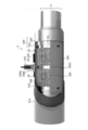
- FIG. 1 shows a pipeline P and a sensor device 1 according to an embodiment.
- FIG. 2 shows magnetic sensors 11 and ultrasonic sensors 12 disposed on a tubular substrate 105.
- FIG. 3 is a partial transparent view of the sensor device 1.
- Fig. 4 shows a sensor housing 106.
- Fig. 5 shows the sensor housing 106 before the joining.
- Fig. 6 shows a method of attaching the sensor device 1.
- Fig. 7 Fig. 7 shows a pipeline monitoring system 5.
- FIG. 8 shows a method of calculating an absolute thickness distribution.
- Fig. 9 shows an exemplary computer 2200 in which a plurality of aspects of the present invention may be embodied wholly or partially.
- FIG. 1 shows a pipeline P and a sensor device 1 according to the present embodiment. Note that upper and lower parts of the figure respectively show cross sections orthogonal to and parallel with a longitudinal direction (also referred to as an axial direction).
- the pipeline P is a pipeline for conveying fluid.
- the pipeline P may transport fossil fuels, and transports a natural resource such as petroleum and natural gas for example in the present embodiment.
- the pipeline P may be disposed in a plant or disposed on the seabed, and may be provided in deep water not deeper than 3000 meters, for example.
- the pipeline P is laid on the seabed by the J-lay method, but may also be laid by the reel method or the S-lay method.
- the pipeline P may be deflected when being laid or after being laid by receiving external force due to landslide and water flow.
- the pipeline P may be made of a magnetic material such as carbon steel.
- the pipeline P may have a pipe diameter (outer diameter) of 323.8 mm.
- the pipeline P may have a thickness of 21.44 mm.
- the pipeline P may be formed by welding and connecting pipes that are each 15 to 20 m long, to have a length of about 10 to 100 km.
- a corrosion resistance layer P10 and a thermal insulation layer P11 may be provided on the outer side of an outer circumference surface P1 of the pipeline P.
- the corrosion resistance layer P10 may have a three layer structure including a thermally welded epoxy resin layer, a copolymer adhesive layer, and a polypropylene layer.
- the thermal insulation layer P11 may foam made of polypropylene resin or the like. Note that even if the corrosion resistance layer P10 and the thermal insulation layer P11 are provided, corrosion (full corrosion or partial corrosion) may occur on the pipeline P. In the lower part of the figure, the corrosion resistance layer P10 and the thermal insulation layer P11 are omitted.
- Sensor devices 1 are disposed on the outer side of the pipeline P, and measure data about the thickness of the pipeline P. If the corrosion resistance layer P10 and the thermal insulation layer P11 are provided on the outer circumference surface P1 of the pipeline P, the sensor devices 1 may be disposed on the inner side of these layers.
- the sensor devices 1 may be dispersed along a longitudinal direction z of the pipeline P, and may be arranged at a 1-km interval, for example.
- the sensor devices 1 each include a plurality of magnetic sensors 11, ultrasonic sensors 12 that are less than the magnetic sensors 11, and one or a plurality of temperature sensors 13, a substrate 105, and a sensor housing 106 that are contained in a case portion 100. The substrate 105 and the sensor housing 106 may not be provided to the sensor device 1.
- the case portion 100 forms an internal space 1000, holding liquid 101, around a part of the outer circumference of the pipeline P in the longitudinal direction z.
- the magnetic sensors 11 and the ultrasonic sensors 12 are each disposed in the liquid 101.
- the case portion 100 may include two end portion members 102 and a case portion main body 103 that define the internal space 1000 together with the outer circumference surface P1 of the pipeline P.
- the liquid 101 is insulative and is insulation oil, for example.
- the liquid 101 may insulate an internal circuit of the sensor device 1 from peripheral conductors while protecting the internal circuit from corrosion.
- the liquid 101 may transmit ultrasonic waves used for measurement by the ultrasonic sensors 12, and may protect the internal circuit of the sensor device 1 from an impact on the pipeline P.
- the liquid 101 may be electrical insulation oil defined in JIS C 2320.
- the two end portion members 102 are disposed on both sides of the internal space 1000 in the longitudinal direction z.
- the end portion members 102 may be formed annularly and coaxially with the pipeline P, and may each be in contact with the outer circumference surface P1 over the entire circumference of the pipeline P.
- the end portion members 102 may each include an annular first supporting surface 1021 and a second supporting surface 1022 on the outer circumference side.
- the first supporting surface 1021 may be provided on an end side of the sensor device 1 in the longitudinal direction z.
- the second supporting surface 1022 may be provided more on the center side of the sensor device 1 than the first supporting surface 1021 in the longitudinal direction z, and may be closer to the outer circumference surface P1 than the first supporting surface 1021. In other words, the second supporting surface 1022 may be at a lower level than the first supporting surface 1021, from the outer circumference surface P1 of the pipeline P.
- the end portion members 102 described above may be made of the same material as the pipeline P.
- the end portion members 102 may each be formed by fitting and welding two annular plates with different diameters.
- the case portion main body 103 extends between the two end portion members 102 in the longitudinal direction z and is in contact with outer circumference surfaces of the end portion members 102 over the entire circumference of the pipeline P.
- the case portion main body 103 is in contact with the first supporting surfaces 1021 of each of the end portion members 102 and is supported by the first supporting surfaces 1021.
- the case portion main body 103 may be formed in a tube coaxial with the pipeline P.
- the case portion main body 103 may be made of the same material as the pipeline P.
- the case portion main body 103 may have an outer diameter of 420 mm, for example, and a thickness of 10 mm to 50 mm, for example.
- the case portion main body may have a length in the longitudinal direction z of 1000 mm, for example.
- the magnetic sensors 11 are each disposed to face the outer circumference surface P1 of the pipeline P.
- the magnetic sensors 11 measure the intensity of a magnetic field leaking from the pipeline P toward the outer circumference side.
- the magnetic sensors 11 may be disposed in the liquid 101, and the liquid 101 may be interposed between each of the magnetic sensors 11 and the outer circumference surface P1 of the pipeline P.
- the magnetic sensors 11 may each measure the magnetic field on the outer circumference side of the pipeline P facing the magnetic sensors 11 with the liquid 101 interposed therebetween.
- the magnetic sensors 11 may each measure the magnetic field intensity (also referred to as magnetic flux density) in three-dimensional directions (in the present embodiment, the longitudinal direction z, a circumference direction ⁇ , and a radial direction r of the pipeline P, for example).
- the measurement region in which the plurality of magnetic sensors 11 measure the magnetic field may seamlessly continue along the circumference direction ⁇ and the longitudinal direction z of the pipeline P.
- the measurement region may extend over 500 mm in the longitudinal direction z, and may extend in the circumference direction ⁇ over the entire circumference of the pipeline P.
- the number of the magnetic sensors 11 provided to the sensor device 1 may be about 600 to 1200.
- the magnetic sensors 11 may each be disposed on the substrate 105.
- the ultrasonic sensors 12 face the outer circumference surface P1, and measure the thickness of the pipeline P in the measurement region in which the plurality of magnetic sensors 11 measure the magnetic field.
- the ultrasonic sensors 12 may be disposed in the liquid 101, and the liquid 101 is interposed between each of the ultrasonic sensors 12 and the outer circumference surface P1 of the pipeline P.
- the ultrasonic sensors 12 may each measure the thickness of the pipeline P facing the ultrasonic sensors 12 with the liquid 101 interposed therebetween.
- the number of the ultrasonic sensors 12 may be smaller than the number of the magnetic sensors 11.
- the number of the ultrasonic sensors 12 may be less than one tenth of the number of the magnetic sensors 11, or may be less than one one-hundredth of the number of the magnetic sensors 11.
- the sensor device 1 may be provided with eight ultrasonic sensors 12.
- the ultrasonic sensors 12 may each be disposed on the substrate 105.
- Power consumption for the measurement performed by the ultrasonic sensors 12 may be larger than power consumption for the measurement performed by the magnetic sensors 11.
- the measurement interval of the ultrasonic sensors 12 may be longer than the measurement interval of the magnetic sensors 11.
- the measurement interval of the magnetic sensors 11 may be once a day, whereas the measurement interval of the ultrasonic sensors 12 may be once a week.
- the magnetic sensors 11 in one of the sensor devices 1 may perform the measurement at the same timing or at timings different from each other.
- the ultrasonic sensors 12 in one of the sensor devices 1 may perform the measurement at the same timing or at timings different from each other.
- the temperature sensors 13 each measure temperature in a measurement environment of the sensor device 1.
- the number of the temperature sensors 13 provided to the sensor device 1 is the same as the total number of the magnetic sensor 11 and the ultrasonic sensor 12.
- the temperature sensors 13 are disposed in the vicinity of the respective magnetic sensors 11 and the respective ultrasonic sensors 12 and measure the temperature of the respective magnetic sensors 11 or the respective ultrasonic sensors 12.
- the liquid 101 may be interposed between each of the temperature sensors 13 and the outer circumference surface P1 of the pipeline P. In the figure, the temperature sensors 13 are shown to be integrated with the respective magnetic sensors 11 and the respective ultrasonic sensors 12.
- the temperature sensor 13 and the magnetic sensor 11 may be separately provided, and the temperature sensor 13 and the ultrasonic sensor 12 may be separately provided.
- the number of the temperature sensors 13 may not be the same as the total number of the ultrasonic sensors 12 and the magnetic sensors 11, and may be one, for example.
- the temperature sensors 13 may not be provided to the sensor device 1.
- the substrate 105 supports each of the magnetic sensors 11, the ultrasonic sensors 12, and the temperature sensors 13, and is provided to face the outer circumference surface P1 of the pipeline P.
- the substrate 105 may be a flexible substrate such as a printed circuit board, and may have one surface provided with the magnetic sensors 11, the ultrasonic sensors 12, and the temperature sensors 13.
- the substrate 105 may be deflected to be formed in a tube coaxial with the pipeline P, with the magnetic sensors 11, the ultrasonic sensors 12, and the temperature sensors 13 provided on the inner side.
- the distance between the substrate 105 and the outer circumference surface of the pipeline P (that is, the thickness of a layer of the liquid 101 more on the inner side than the substrate 105) may be 10 mm.
- a uniform distance of 10 mm is provided between the outer circumference surface P1 of the pipeline P and each of the magnetic sensors 11, the ultrasonic sensors 12, and the temperature sensors 13.
- the substrate 105 may be supported by the second supporting surfaces 1022 of the end portion members 102 of the case portion 100.
- the substrate 105 is fixed to the sensor housing 106 to be supported by the second supporting surfaces 1022 via the sensor housing 106.
- the substrate 105 may be made of a nonmetal material so as not to negatively affect the magnetic sensors 11.
- the substrate 105 may be made of any resin such as polyimide or polyester.
- the sensor housing 106 is a tubular member that protects each of the magnetic sensors 11, the ultrasonic sensors 12, and the temperature sensors 13, and has an inner circumference surface on which the substrate 105 is fixed.
- the sensor housing 106 may extend in the longitudinal direction z of the pipeline P, and be in contact with the second supporting surfaces 1022 over the entire circumference of the end portion members 102.
- the distance between the sensor housing 106 and the case portion main body 103 (that is, the thickness of a layer of the liquid 101 more on the outer side than the sensor housing 106) may be 10 mm.
- the sensor housing 106 divides the internal space 1000 into the inner circumference side and the outer circumference side. Still, the liquid 101 may be flowable between these sides via through holes (not shown) formed in the sensor housing 106 and the substrate 105.
- the sensor housing 106 may be made of a nonmetal material so as not to negatively affect the magnetic sensors 11.
- the sensor housing 106 may be made of a thermoplastic resin such as polyether ether ketone (PEEK).
- PEEK polyether ether ketone
- the sensor housing 106 may have a thickness of 10 mm, for example.
- the inner circumference surface or the outer circumference surface of the sensor housing 106 may be provided with a plate-shaped magnetic shield that magnetically isolates each of the magnetic sensors 11 from the case portion main body 103.
- the magnetic shield may be formed of Mu-metal having a thickness of 1 mm, for example.
- the plurality of magnetic sensors 11 are provided to face the outer circumference surface P1 of the pipeline P.
- the intensity distribution of the magnetic field leaking from the pipeline P toward the outer circumference side, and thus the relative thickness distribution can be calculated from the measurement results from the magnetic sensors 11.
- the ultrasonic sensors 12 are provided to measure the thickness of the pipeline P in the measurement region of the magnetic sensors 11.
- the absolute thickness of the pipeline P in the magnetic field measurement region can be measured.
- a relationship between the absolute thickness and the relative thickness at the measurement position of the ultrasonic sensors 12 can be calculated.
- the absolute thickness distribution of the pipeline P can be accurately calculated.
- the sensor device 1 is provided with one or a plurality of temperature sensors 13, so that measurement error can be reduced through temperature compensation, when the measurement results from the magnetic sensors 11 and the ultrasonic sensors 12 are affected by the temperature of the measurement environment.
- the temperature sensors 13 are disposed in the vicinity of the respective ultrasonic sensors 12, so that the measurement error of the ultrasonic sensors 12 can be reliably reduced.
- the number of ultrasonic sensors 12 is smaller than the number of magnetic sensors 11. Thus, the measurement can be performed with power consumption smaller than that in a case where the absolute thickness distribution is mainly measured by the ultrasonic sensors 12.
- the measurement interval of the ultrasonic sensors 12 is longer than the measurement interval of the magnetic sensors 11. Thus, the power consumption of the sensor device 1 can be reliably reduced.
- the magnetic sensors 11, the ultrasonic sensors 12, and the temperature sensors 13 are provided inside the insulating liquid 101, and thus can be prevented from corrosion. Even when the pipeline P is disposed in a high pressure environment such as the deep sea, the sensors can be protected by maintaining the internal pressure of the case portion 100.
- the liquid 101 is interposed between the outer circumference surface P1 of the pipeline P and each of the magnetic sensors 11, the ultrasonic sensors 12, and the temperature sensors 13. Thus, the sensors are prevented from breaking even when the pipeline P is deflected.
- the liquid 101 serves as an ultrasonic-wave transmitting medium, so that the absolute thickness of the pipeline P can be reliably measured.
- the end portion members 102 of the case portion 100 are each provided with the annular first supporting surface 1021 and the annular second supporting surface 1022.
- the annular first supporting surface 1021 is provided on the corresponding end side in the longitudinal direction z and supports the case portion main body 103.
- the annular second supporting surface 1022 is provided more on the center side in the longitudinal direction z and is closer to the outer circumference surface P1 of the pipeline P than the first supporting surface 1021 and supports the substrate 105.
- the substrate 105 is a flexible substrate and thus can be easily bent to face around the outer circumference surface P1 of the pipeline P.
- the substrate 105 is fixed to the inner circumference surface of the tubular sensor housing 106.
- each of the magnetic sensors 11, the ultrasonic sensors 12, and the temperature sensors 13 can be more reliably prevented from breaking due to the deflection of the pipeline P.
- the magnetic sensors 11, the ultrasonic sensors 12, and the temperature sensors 13 can be positioned with respect to the outer circumference surface P1 of the pipeline P, to be separated from the outer circumference surface P1 of the pipeline P by a uniform distance.
- FIG. 2 shows the magnetic sensors 11, the ultrasonic sensors 12, and the temperature sensors 13 disposed on the tubular substrate 105.
- the substrate 105 may have a length of 500 mm in the longitudinal direction z.
- the substrate 105 may have an outer diameter (diameter) that is larger than the outer diameter of the pipeline P (323.8 mm, for example) by 20 mm.
- the magnetic sensors 11 may be arranged at an equal interval along each of the circumference direction ⁇ and the longitudinal direction z of the pipeline P.
- the distance between adjacent magnetic sensors 11 may be 40 mm.
- Four ultrasonic sensors 12 may be arranged at an equal interval along the circumference direction ⁇ of the pipeline P and two ultrasonic sensors 12 may be arranged at an equal interval along the longitudinal direction z.
- the ultrasonic sensors 12 may each be arranged at a position not overlapping with any of the magnetic sensors 11.
- the temperature sensors 13 may each be arranged in the vicinity of a corresponding one of the magnetic sensors 11 and the ultrasonic sensors 12. In the figure, the temperature sensors 13 are each shown to be integrated with a corresponding one of the magnetic sensors 11 and the respective ultrasonic sensors 12.
- Fig. 3 is a partial transparent view of the sensor device 1.
- the sensor device 1 may further include a connector 110, a transmission unit 14, a power supply unit 15, and a liquid injection port 16.
- the connector 110 is provided through the case portion 100 and electrically connected to the substrate 105.
- the connector 110 may be formed through the case portion main body 103 of the case portion 100.
- the sensor housing 106 is provided with a through hole 1060, and a terminal 1050 of the substrate 105 may be inserted through the through hole 1060.
- the terminal 1050 may be electrically connected to each of the magnetic sensors 11, the ultrasonic sensors 12, and the temperature sensors 13.
- the connector 110 is electrically connected to the substrate 105 via the terminal 1050.
- the connector 110 may be electrically connected to the transmission unit 14 and the power supply unit 15 outside the case portion 100.
- the transmission unit 14 is provided outside the case portion 100, and transmits measurement data from each of the magnetic sensors 11, the ultrasonic sensors 12, and the temperature sensors 13.
- the transmission unit 14 may transmit the data through wired communications, or through wireless communications.
- the sensor devices 1 provided to the pipeline P may be connected to a calculation device 6 (shown in Fig. 7) and a relay device through a communication cable.
- a calculation device 6 shown in Fig. 7
- a relay device through a communication cable.
- an unmanned submarine may cruise around the sensor devices 1 to collect the data.
- the power supply unit 15 supplies power to the components of the sensor device 1 including the magnetic sensors 11, the ultrasonic sensors 12, the temperature sensors 13, and the transmission unit 14 in the present embodiment.
- the power supply unit 15 may supply power obtained by energy harvesting.
- the power supply unit 15 may generate power through temperature difference power generation utilizing a temperature difference between the temperature of the fossil fuel flowing in the pipeline P (for example, a natural resource in the present embodiment) and the temperature of the environment outside the pipeline P (for example, underwater temperature in the present embodiment).
- the internal temperature of the natural resource may be about 40 to 100°C, whereas the underwater temperature may be about 2°C.
- the power supply unit 15 may include a thermoelectric element 150 that converts thermal energy into power energy and a battery (not shown) that stores the power energy thus generated.
- the thermoelectric element 150 may be provided to be in contact with the outer circumference surface P1 of the pipeline P and the sea water outside the pipeline P.
- the thermoelectric element 150 may be in contact with the outer circumference surface P1 of the pipeline P via the case portion main body 103 and the end portion members 102 or the liquid 101.
- the corrosion resistance layer P10 and the thermal insulation layer P11 are provided on the outer circumference of the pipeline P, the thermoelectric element 150 may be exposed from these layers.
- the liquid injection port 16 is formed through the case portion 100.
- the liquid injection port 16 may be formed through the case portion main body 103.
- the liquid injection port 16 is used for injecting the liquid 101 into the internal space 1000 of the case portion 100.
- the transmission unit 14, connected to the substrate 105 via the connector 110, is provided outside the case portion 100.
- the measurement data can be reliably transmitted while protecting each of the magnetic sensors 11, the ultrasonic sensors 12, and the temperature sensors 13 with the case portion 100.
- the measurement can be performed without supplying power to the sensor device 1 from the external.
- a supporting band 1051 extending in the circumference direction ⁇ may be provided at a center portion of the substrate 105 in the longitudinal direction z.
- the supporting band 1051 may be fixed to the inner circumference surface of the sensor housing 106 over the entire circumference direction ⁇ , so that a uniform distance between the substrate 105 and the outer circumference surface P1 of the pipeline P can be maintained.
- Fig. 4 shows the sensor housing 106.
- the sensor housing 106 has at least one seam 1065 extending in the longitudinal direction z.
- the sensor housing 106 has two seams 1065.
- the sensor housing 106 described above has the seams 1065 extending in the longitudinal direction z, and thus is formed with at least two segments 1066 joined to each other in the circumference direction ⁇ .
- the substrate 105 can be easily fixed to the inner circumference surface of the tubular sensor housing 106.
- the sensor housing 106 may include a plurality of segments 1066 joined to each other in the circumference direction ⁇ .
- the sensor housing 106 is formed by: bringing the segments 1066, with the inner side surfaces to which the substrate 105 is fixed, in contact with each other around the pipeline P; and fixing the segments 1066 to the second supporting surfaces 1022 of the end portion members 102 of the case portion 100 using a plurality of headless screws 1068.
- the sensor housing 106 may be formed by joining the sensor segments 1066 to each other.
- Fig. 6 shows a method of attaching the sensor device 1.
- the sensor device 1 may be attached to the pipeline P through steps shown in Section (1) to Section (7) in the figure.
- the end portion members 102 of the case portion 100 are fixed to the outer circumference surface P1 of the pipeline P.
- the end portion members 102 may be welded to the outer circumference surface P1 of the pipeline P.
- the sensor housing 106 is attached between the end portion members 102. As shown in Fig. 5, the sensor housing 106 may be fixed to the second supporting surfaces 1022 of the end portion members 102 by using the headless screws 1068.
- the substrate 105 to which the magnetic sensors 11 and the ultrasonic sensors 12 are disposed may be fixed to the inner side of the sensor housing 106.
- the case portion main body 103 is fixed to the first supporting surfaces 1021 of the end portion member 102.
- the case portion main body 103 may be welded to the first supporting surfaces 1021.
- the case portion main body 103 is provided with a connector port 1100 through which the connector 110 is inserted.
- the corrosion resistance layer P10 is provided on the outer circumferences of the pipeline P and the case portion 100.
- the internal space 1000 of the case portion 100 is filled with the liquid 101 from an injection tube 160 through the liquid injection port 16.
- the connector 110 is inserted through the connector port to be connected to the substrate 105.
- the thermal insulation layer P11 is provided on the outer circumferences of the pipeline P and the case portion 100.
- Fig. 7 shows a pipeline monitoring system 5.
- the pipeline monitoring system 5 monitors the corrosion of the pipeline P, and includes the plurality of sensor device 1 attached to the pipeline P and the calculation device 6.
- the calculation device 6 calculates a thickness distribution of the pipeline P in a mounted region of each of the sensor devices 1, based on the measurement result from the sensor device 1.
- the calculation device 6 includes a communication unit 60, a temperature compensation unit 61, a first calculation unit 62, a second calculation unit 63, a third calculation unit 64, and a switching unit 65.
- the communication unit 60 receives the measurement data from each of the sensor devices 1.
- the communication unit 60 may be capable of communicating with each of the sensor devices 1 through a network 600 (for example, the Internet or a dedicated line).
- the communication unit 60 may supply the measurement data thus received to the temperature compensation unit 61.
- the temperature compensation unit 61 performs temperature compensation on the measurement result from the sensor device 1.
- the temperature compensation unit 61 may perform the temperature compensation on the measurement data indicating the measurement result from each of the magnetic sensors 11 (also referred to as magnetic field data) and the measurement data indicating the measurement result from the each of the ultrasonic sensors 12 (also referred to as ultrasonic data) among the received measurement data, based on the measurement data indicating the measurement result from each of the temperature sensors 13 (also referred to as temperature data).
- the temperature compensation unit 61 may store in advance a table or the like indicating association among the temperature of the measurement environment and the properties of the magnetic sensors 11 and the ultrasonic sensors 12, and perform the temperature compensation by using the table.
- the magnetic field data, the ultrasonic data, and the temperature data may include identification information on the sensors that have measured the data.
- the calculation device 6 may store in advance a table indicating association between the identification information on each of the magnetic sensors 11 and the ultrasonic sensors 12 and the identification information on the temperature sensor 13 disposed in the vicinity of the sensors.
- the temperature compensation unit 61 may perform the temperature compensation by using the temperature of each of the magnetic sensors 11 as the temperature of the temperature sensor 13 in the vicinity of the magnetic sensor 11.
- the temperature compensation unit 61 may perform the temperature compensation by using the temperature of each of the ultrasonic sensors 12 as the temperature of the temperature sensor 13 in the vicinity of the ultrasonic sensor 12.
- the calculation device 6 may store in advance an arrangement table associating in advance the identification information on each sensor and a position of the sensor in the sensor device 1 (for example, a position in a cylindrical coordinate system in the present embodiment).
- the temperature compensation unit 61 may use the arrangement table to calculate the temperature distribution in the measurement region based on the measurement results from the plurality of temperature sensors 13 and determine the temperature of each of the magnetic sensors 11 and the ultrasonic sensors 12.
- the temperature compensation unit 61 may supply the magnetic field data after the temperature compensation to the first calculation unit 62.
- the temperature compensation unit 61 may supply the ultrasonic data after the temperature compensation to the second calculation unit 63. Note that the temperature compensation unit 61 may not be provided to the calculation device 6. In such a case, the communication unit 60 may supply the magnetic field data and the ultrasonic data, in the received measurement data, respectively to the first calculation unit 62 and the second calculation unit 63.
- the first calculation unit 62 calculates the relative thickness distribution in the measurement region of the plurality of magnetic sensors 11 based on the magnetic field data from each of the magnetic sensors 11.
- the first calculation unit 62 may use the arrangement table described above to determine the magnetic field intensity obtained from each of the magnetic sensors 11 as the magnetic field intensity at the measurement position of the magnetic sensor 11, to calculate the magnetic field intensity distribution on the outer circumference surface P1 of the pipeline P.
- the first calculation unit 62 may calculate the relative thickness distribution based on the magnetic field intensity distribution thus calculated.
- the first calculation unit 62 may supply the relative thickness distribution thus calculated to the second calculation unit 63 and the third calculation unit 64.
- the second calculation unit 63 calculates a value of ratio between the absolute thickness of the pipeline P and the relative thickness in the relative thickness distribution (also referred to as a thickness ratio).
- This absolute thickness means a thickness that is not a relative value but an absolute value.
- the second calculation unit 63 may calculate the thickness ratio based on the ultrasonic data from each of the ultrasonic sensors 12 and the relative thickness obtained at the measurement position of the ultrasonic sensor 12 in the relative thickness distribution obtained by the first calculation unit 62.
- the second calculation unit 63 may supply the thickness ratio thus calculated to the third calculation unit 64. For example, for each of the ultrasonic sensors 12, the second calculation unit 63 may calculate the thickness ratio at the position of the ultrasonic sensor 12, and supply the thickness ratio to the third calculation unit 64.
- the third calculation unit 64 calculates the absolute thickness distribution of the pipeline P in the measurement region, based on the thickness ratio and the relative thickness distribution. For example, the third calculation unit 64 may multiply the relative thickness at one position in the relative thickness distribution by the value of ratio of the absolute thickness to the relative thickness, to calculate the absolute thickness at the position. The third calculation unit 64 may multiply the relative thickness at each position by the thickness ratio at the position of the ultrasonic sensor 12 in the vicinity of the position (the closest ultrasonic sensor 12, for example), to calculate the absolute thickness at each position. The third calculation unit 64 may calculate the absolute thickness at each position of the pipeline P to calculate the absolute thickness distribution of the pipeline P. The third calculation unit 64 may output the thickness distribution thus calculated to the outside. The third calculation unit 64 may also output the thickness distribution calculated to the second calculation unit 63.
- the switching unit 65 outputs a signal for instructing switching of calculation processing to the second calculation unit 63. Calculation processing after the switching will be described in detail later.
- the switching unit 65 may output the signal when a magnetization state of the pipeline P changes, and may output the signal when pigging is performed on the pipeline P, for example.
- the switching unit 65 may output the signal in response to reception of a pigging completion notification from a pigging control device (not shown), or may output the signal in response to an operation from an operator that has received a pigging completion report.
- This pigging may be a practice of performing maintenance and thickness measurement on the pipeline P with a device known as pigs inserted into the pipeline P.
- the pigs may be magnetized, and thus may change the magnetization state of the pipeline P.
- the magnetization of the pigs may be too weak to directly affect the magnetic sensors 11.
- the thickness distribution of the pipeline P in the mounted region of each of the sensor devices 1 is calculated based on the measurement result from the sensor device 1, whereby thinning of the pipeline P can be detected and maintenance can be performed therefor swiftly.
- the relative thickness distribution in the measurement region is calculated based on the measurement result from each of the magnetic sensors 11.
- the value of ratio between the absolute thickness and the relative thickness is calculated based on the measurement result from the ultrasonic sensors 12 and the relative thickness obtained at the measurement position in the relative thickness distribution.
- the absolute thickness distribution in the measurement region is calculated based on the value of ratio and the relative thickness distribution.
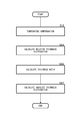
- Fig. 8 shows a method of calculating the absolute thickness distribution.
- the calculation device 6 calculates the absolute thickness distribution through processing in steps S11 to S17.
- each of the sensor devices 1 transmits the measurement result from each of the magnetic sensors 11 to the calculation device 6 at an interval shorter than the transmission interval of the measurement result from each of the ultrasonic sensors 12.
- Each of the temperature sensors 13 transmits the measurement results to the calculation device 6 at the same interval as the transmission interval of the measurement result from the magnetic sensor 11 or the ultrasonic sensor 12 in the vicinity of the temperature sensor 13.
- the temperature compensation unit 61 performs the temperature compensation on the measurement result from the sensor device 1.
- the temperature sensors 13 are disposed in the vicinity of the respective magnetic sensors 11 and the respective ultrasonic sensors 12.
- the temperature compensation unit 61 performs the temperature compensation on the measurement result from each of the magnetic sensors 11 and the ultrasonic sensors 12 by using the measurement temperature from the corresponding temperature sensor 13.
- step S13 the first calculation unit 62 calculates the relative thickness distribution in the measurement region of each of the sensor device 1.
- the first calculation unit 62 may calculate the relative thickness distribution through a method disclosed in Japanese Patent No. 6447641.
- the first calculation unit 62 may calculate a three-dimensional magnetic field intensity distribution (in the longitudinal direction z, the circumference direction ⁇ , and the radial direction r of the pipeline P in the present embodiment, for example) based on the magnetic field data from each of the magnetic sensors 11.
- the first calculation unit 62 may calculate a magnetic dipole density distribution in the measurement region based on the magnetic field intensity distribution, and calculate the relative thickness distribution (also referred to as a thinning distribution) in the measurement region based on the magnetic dipole density distribution.
- the first calculation unit 62 may calculate the magnetic dipole density distribution in the z direction in the measurement region, based on the magnetic flux density in the z direction measured by each of the magnetic sensors 11 and the magnetization amount in each of the z direction, the ⁇ direction, and the r direction in the measurement region. Similarly, the first calculation unit 62 may calculate the magnetic dipole density distribution in the ⁇ direction in the measurement region, based on the magnetic flux density in the ⁇ direction measured by each of the magnetic sensors 11 and the magnetization amount in each of the z direction, the ⁇ direction, and the r direction in the measurement region.
- the first calculation unit 62 may calculate the magnetic dipole density distribution in the r direction in the measurement region, based on the magnetic flux density in the r direction measured by each of the magnetic sensors 11 and the magnetization amount in each of the z direction, the ⁇ direction, and the r direction in the measurement region.
- the first calculation unit 62 may calculate the relative thickness distribution based on the magnetic dipole density distributions in the z direction, the ⁇ direction, and the r direction, or may calculate the relative thickness distribution based on information obtained by averaging the distributions.
- the second calculation unit 63 calculates the thickness ratio.
- the second calculation unit 63 may calculate the thickness ratio based on the absolute thickness most recently obtained for a position and the relative thickness most recently obtained for the position. For example, the second calculation unit 63 may calculate the thickness ratio based on the measurement result most recently obtained by each of the ultrasonic sensors 12 (the absolute thickness at the measurement position of the ultrasonic sensor 12) and the relative thickness obtained at the measurement position in the relative thickness distribution most recently calculated by the first calculation unit 62.
- the second calculation unit 63 may calculate the thickness ratio based on the absolute thickness at any position in the absolute thickness distribution most recently calculated by the third calculation unit 64, and the relative thickness obtained at the position in the relative thickness distribution most recently calculated by the first calculation unit 62.
- the term "most recently” indicates closeness in terms of time, and may be the time point closest to the current time point, for example.
- the second calculation unit 63 may switch the calculation processing for the thickness ratio in response to the signal supplied from the switching unit 65.
- the second calculation unit 63 may calculate the thickness ratio based on the measurement result most recently obtained by each of the ultrasonic sensors 12 (the absolute thickness at the measurement position of the ultrasonic sensor 12) and the relative thickness obtained at the measurement position of the ultrasonic sensor in the relative thickness distribution newly calculated by the first calculation unit 62 after the second calculation unit 63 has received the signal.
- the second calculation unit 63 may calculate the thickness ratio based on the absolute thickness at any position in the absolute thickness distribution most recently calculated by the third calculation unit 64 and the relative thickness obtained for the position in the relative thickness distribution newly calculated by the first calculation unit 62 after the second calculation unit 63 has received the signal.
- step S17 the third calculation unit 64 calculates the absolute thickness distribution of the pipeline P in the measurement region based on the thickness ratio and the relative thickness distribution.
- the thickness ratio is calculated based on the measurement result most recently obtained from each of the ultrasonic sensors 12 and the relative thickness calculated most recently at the measurement position of the ultrasonic sensor 12, or based on the absolute thickness most recently calculated at any position and the relative thickness most recently calculated at the position.
- the absolute thickness distribution can be calculated by calculating the thickness ratio, even when the measurement result cannot be acquired from the ultrasonic sensors 12.
- the thickness ratio is calculated based on the measurement result most recently obtained by each of the ultrasonic sensors 12 and the relative thickness newly measured at the measurement position of the ultrasonic sensor 12 after the reception of the signal, or is calculated based on the absolute thickness at any position most recently calculated and the relative thickness newly calculated at the position after the reception of the signal.
- the magnetic sensors 11 and the ultrasonic sensors 12 described to be disposed in the liquid 101 in the above-described embodiment may be disposed in the liquid 101 while being in indirect contact with the liquid 101.
- at least one kind of sensors of the magnetic sensors 11 or the ultrasonic sensors 12 or the entirety of the sensors and the substrate 105 may be disposed in the liquid 101 while being sealed in resin not affecting the measurement result.
- resin for example, epoxy, urethane, silicon, or the like may be used as this resin.
- the liquid 101 described to be interposed between the ultrasonic sensor 12 and the outer circumference surface P1 of the pipeline P may not be interposed therebetween.
- the ultrasonic sensor 12 may be in direct contact with the outer circumference surface P1 or may be in indirect contact with the outer circumference surface P1 via adhesive or buffer agent.
- the measurement interval of the ultrasonic sensor 12 described to be longer than the measurement interval of the magnetic sensor 11 may be the same as or shorter than the measurement interval of the magnetic sensor 11.
- the sensor device 1 described to transmit the measurement result from each of the magnetic sensors 11 to the calculation device 6 at an interval shorter than a transmission interval of the measurement result from each of the ultrasonic sensors 12, may transmit the measurement results from magnetic sensors 11 and the ultrasonic sensors 12 at the same interval or may transmit the measurement result from the magnetic sensors 11 to the calculation device 6 at an interval longer than a transmission interval of the measurement result from the ultrasonic sensors 12.
- the power consumption of the ultrasonic sensor 12 for the measurement described to be larger than the power consumption of the magnetic sensor 11 may be the same as or smaller than the power consumption of the magnetic sensor 11.
- Blocks herein may illustrate (1) steps of processes of executing operations or (2) sections in a device responsible for executing operations. Particular steps and sections may be implemented by a dedicated circuitry, a programmable circuitry that is supplied together with computer-readable instructions stored on a computer-readable medium, or by a processor that is supplied together with computer-readable instructions stored on a computer-readable medium.
- the dedicated circuitry may include digital or analog hardware circuits. It may also include integrated circuits (IC) or discrete circuits.
- the programmable circuitry may include reconfigurable hardware circuits that include a logical AND, a logical OR, a logical XOR, a logical NAND, a logical NOR, other logical operations, a flip-flop, a register, and memory elements such as a field-programmable gate array (FPGA) and a programmable logic array (PLA).
- FPGA field-programmable gate array
- PLA programmable logic array
- the computer-readable medium may include any tangible device that can store instructions to be executed by an appropriate device.
- the computer-readable medium having the instructions stored on the device incorporates a product including instructions that can be executed in order to create means for executing operations specified in the flow charts or the block diagrams.
- Examples of the computer-readable medium may include: an electronic storage medium; a magnetic storage medium; an optical storage medium; an electromagnetic storage medium; and a semiconductor storage medium.
- Computer-readable media may include a floppy disk, a diskette, a hard disk, a random access memory (RAM), a read-only memory (ROM), an erasable programmable read-only memory (EPROM or Flash memory), an electrically erasable programmable read-only memory (EEPROM), a static random access memory (SRAM), a compact disc read-only memory (CD-ROM), a digital versatile disk (DVD), a BLU-RAY (registered trademark) disc, a memory stick, an integrated circuit card, etc.
- RAM random access memory
- ROM read-only memory
- EPROM or Flash memory erasable programmable read-only memory
- EEPROM electrically erasable programmable read-only memory
- SRAM static random access memory
- CD-ROM compact disc read-only memory
- DVD digital versatile disk
- BLU-RAY registered trademark
- Computer-readable instructions may include assembler instructions, instruction-set-architecture (ISA) instructions, machine instructions, machine dependent instructions, microcode, firmware instructions, state-setting data, or either source code or object code written in any combination of one or more programming languages, including an object oriented programming language such as Smalltalk, JAVA (registered trademark), C++, etc., and conventional procedural programming languages, such as the "C" programming language or similar programming languages.
- ISA instruction-set-architecture
- Machine instructions machine dependent instructions
- microcode firmware instructions
- state-setting data or either source code or object code written in any combination of one or more programming languages, including an object oriented programming language such as Smalltalk, JAVA (registered trademark), C++, etc., and conventional procedural programming languages, such as the "C" programming language or similar programming languages.
- the computer-readable instruction may be provided to a processor of general purpose computer, a special purpose computer, another programmable a data-processing device, or to a programmable circuitry, locally, via local area network (LAN), or wide area network (WAN) such as the Internet.
- the computer-readable instruction may be executed in order to create means for executing operations specified by the flow charts or block diagrams.
- processors include computer processors, processing units, microprocessors, digital signal processors, controllers, microcontrollers, etc.
- Fig. 9 shows an exemplary computer 2200 in which a plurality of aspects of the present invention may be embodied wholly or partially.
- a program that is installed in the computer 2200 can cause the computer 2200 to function as or perform operations associated with apparatuses of the embodiments of the present invention or one or more sections thereof, or cause the computer 2200 to perform processes of the embodiments of the present invention or steps thereof.
- Such programs may be executed by a CPU 2212 in order to cause the computer 2200 to execute particular operations associated with some or all of the flow charts and the blocks of the block diagrams described herein.
- the computer 2200 includes the CPU 2212, a RAM 2214, a graphics controller 2216, and a display device 2218, and they are connected to each other with a host controller 2210.
- the computer 2200 also include input/output units such as a communication interface 2222, a hard disk drive 2224, a DVD-ROM drive 2226, and an IC card drive, and they are connected to the host controller 2210 via an input/output controller 2220.
- the computer also includes legacy input/output units such as a ROM 2230 and a keyboard 2242, and they are connected to the input/output controller 2220 via an input/output chip 2240.
- the CPU 2212 operates according to programs stored in the ROM 2230 and the RAM 2214 and thereby controls each unit.
- the graphics controller 2216 acquires image data generated by the CPU 2212 on a frame buffer or the like provided in the RAM 2214, or in the graphics controller 2216, to display the image data on the display device 2218.
- the communication interface 2222 communicates with another electronic device via network.
- the hard disk drive 2224 stores programs and data used by the CPU 2212 in the computer 2200.
- the DVD-ROM drive 2226 reads out programs or data from a DVD-ROM 2201 and provides the programs or data to the hard disk drive 2224 via the RAM 2214.
- the IC card drive reads out programs and data from an IC card or writes programs and data into the IC card.
- the ROM 2230 stores therein a boot program and the like to be executed by the computer 2200 at the time of activation or a program that depends on hardware of the computer 2200.
- the input/output chip 2240 may also connect various input/output units to the input/output controller 2220 via a parallel port, a serial port, a keyboard port, a mouse port, or the like.
- Programs are provided by a computer-readable medium such as the DVD-ROM 2201 or the IC card.
- the programs are read out from the computer-readable medium and installed on the hard disk drive 2224, the RAM 2214, or the ROM 2230, which are also examples of the computer-readable medium, to be executed by the CPU 2212.
- the information processing described in these programs is read out by the computer 2200 to provide linkage between the programs and the above-described various types of hardware resources.
- An apparatus or method may be constituted by realizing the operation or processing of information in accordance with the usage of the computer 2200.
- the CPU 2212 may execute a communication program loaded into the RAM 2214 and instructs the communication interface 2222 to implement the communication processing according to processing described in the communication program.
- the communication interface 2222 reads out transmission data stored in a transmission buffer processing region provided in a recording medium such as the RAM 2214, the hard disk drive 2224, the DVD-ROM 2201, or the IC card, and then sends the read transmission data to network or writes data received from the network into a reception buffer processing region provided in the recording medium or the like.
- the CPU 2212 may operate such that all or a necessary portion of a file or database stored on an external recording medium such as the hard disk drive 2224, the DVD-ROM drive 2226 (DVD-ROM 2201) or the IC card is read by the RAM 2214. Then, it may execute various types of processing on data in the RAM 2214. The CPU 2212 subsequently writes back the processed data to the external recording medium.
- an external recording medium such as the hard disk drive 2224, the DVD-ROM drive 2226 (DVD-ROM 2201) or the IC card is read by the RAM 2214. Then, it may execute various types of processing on data in the RAM 2214. The CPU 2212 subsequently writes back the processed data to the external recording medium.
- Various types of information such as various types of programs, data, tables, and databases may be stored on a recording medium, and then information processing may be performed on the information.
- the CPU 2212 may execute various types of processing which include various types of operations, information processing, conditional judgement, conditional branch, unconditional branch, information searching/replacement, and the like as described throughout in the disclosure herein or specified by instruction sequences of programs. Then, the CPU 2212 writes back the result into the RAM 2214. Also, the CPU 2212 may search for information in files, database, or the like in a recording medium.
- the CPU 2212 may search an entry, out of the plurality of entries, that has an attribute value of the first attribute matching a specified condition. Then, the CPU 2212 may read out an attribute value of the second attribute stored in the entry and acquire the attribute value of the second attribute associated with the first attribute that satisfies the predetermined condition.
- the above-described programs or the software modules may be stored in a computer-readable medium in or near the computer 2200.
- a recording medium such as a hard disk or a RAM provided in a server system that is connected to a dedicated communication network or the Internet can be used as the computer-readable medium, whereby a program is provided to the computer 2200 via the network.
- thermoelectric element 160 injection tube, 600 network, 1000 internal space, 1021 first supporting surface, 1022 second supporting surface, 1050 terminal, 1051 supporting band, 1060 through hole, 1065 seam, 1066 segment, 1068 headless screw, 1100 connector port, 2200 computer, 2201 DVD-ROM, 2210 host controller, 2212 CPU, 2214 RAM, 2216 graphics controller, 2218 display device, 2220 input/output controller, 2222 communication interface, 2224 hard disk drive, 2226 DVD-ROM drive, 2230 ROM, 2240 input/output chip, 2242 keyboard, P pipeline, P1 outer circumference surface, P10 corrosion resistance
Landscapes
- Physics & Mathematics (AREA)
- General Physics & Mathematics (AREA)
- Condensed Matter Physics & Semiconductors (AREA)
- Life Sciences & Earth Sciences (AREA)
- Health & Medical Sciences (AREA)
- Environmental & Geological Engineering (AREA)
- General Health & Medical Sciences (AREA)
- Pathology (AREA)
- Analytical Chemistry (AREA)
- Biochemistry (AREA)
- Environmental Sciences (AREA)
- Ecology (AREA)
- Immunology (AREA)
- Chemical & Material Sciences (AREA)
- Biodiversity & Conservation Biology (AREA)
- Engineering & Computer Science (AREA)
- Toxicology (AREA)
- Investigating Or Analyzing Materials By The Use Of Ultrasonic Waves (AREA)
- Length Measuring Devices Characterised By Use Of Acoustic Means (AREA)
- Investigating Or Analyzing Materials By The Use Of Magnetic Means (AREA)
- Measurement Of Length, Angles, Or The Like Using Electric Or Magnetic Means (AREA)
Abstract
Une distribution d'épaisseur absolue ne peut pas être calculée avec précision avec une technique classique. L'invention concerne un dispositif de capteur qui comprend une pluralité de capteurs magnétiques agencés pour faire face à une surface de circonférence externe d'un pipeline et des capteurs ultrasonores agencés pour faire face à la surface de circonférence externe et mesurer une épaisseur du pipeline dans une région de mesure dans laquelle la pluralité de capteurs magnétiques mesurent un champ magnétique, les capteurs ultrasonores étant inférieurs en nombre à la pluralité de capteurs magnétiques.
Priority Applications (1)
| Application Number | Priority Date | Filing Date | Title |
|---|---|---|---|
| US17/427,673 US11959851B2 (en) | 2019-03-28 | 2019-12-27 | Pipeline thickness measurement sensor device |
Applications Claiming Priority (2)
| Application Number | Priority Date | Filing Date | Title |
|---|---|---|---|
| JP2019065081A JP6988854B2 (ja) | 2019-03-28 | 2019-03-28 | センサ装置、演算装置、パイプライン監視システム、演算方法およびプログラム |
| JP2019-065081 | 2019-03-28 |
Publications (1)
| Publication Number | Publication Date |
|---|---|
| WO2020194975A1 true WO2020194975A1 (fr) | 2020-10-01 |
Family
ID=69174564
Family Applications (1)
| Application Number | Title | Priority Date | Filing Date |
|---|---|---|---|
| PCT/JP2019/051633 Ceased WO2020194975A1 (fr) | 2019-03-28 | 2019-12-27 | Dispositif de capteur et système de surveillance de pipeline |
Country Status (3)
| Country | Link |
|---|---|
| US (1) | US11959851B2 (fr) |
| JP (1) | JP6988854B2 (fr) |
| WO (1) | WO2020194975A1 (fr) |
Families Citing this family (3)
| Publication number | Priority date | Publication date | Assignee | Title |
|---|---|---|---|---|
| JP2022185657A (ja) * | 2021-06-03 | 2022-12-15 | アズビル株式会社 | 光学分析装置 |
| JP7647711B2 (ja) * | 2022-08-30 | 2025-03-18 | 横河電機株式会社 | 磁気パイプセンサ |
| US11953161B1 (en) | 2023-04-18 | 2024-04-09 | Intelcon System C.A. | Monitoring and detecting pipeline leaks and spills |
Citations (6)
| Publication number | Priority date | Publication date | Assignee | Title |
|---|---|---|---|---|
| JPH0147641B2 (fr) | 1982-02-17 | 1989-10-16 | Daikin Kogyo Co Ltd | |
| WO2009156862A2 (fr) * | 2008-06-27 | 2009-12-30 | Pii (Canada) Limited | Contrôle non destructif intégré multi-capteurs |
| WO2013044350A1 (fr) * | 2011-09-26 | 2013-04-04 | Ontario Power Generation Inc. | Contrôle par matrice à ultrasons |
| EP3236252A1 (fr) * | 2016-04-22 | 2017-10-25 | Yokogawa Electric Corporation | Système et procédé de détection d'amincissement |
| CN108226277A (zh) * | 2017-12-28 | 2018-06-29 | 哈尔滨工业大学 | 一种漏磁、电磁超声和涡流复合式管道外检测探头 |
| US20180259486A1 (en) * | 2017-03-07 | 2018-09-13 | The Charles Stark Draper Laboratory, Inc. | Augmented Reality Visualization for Pipe Inspection |
Family Cites Families (11)
| Publication number | Priority date | Publication date | Assignee | Title |
|---|---|---|---|---|
| DE10109568A1 (de) * | 2001-01-17 | 2002-07-25 | Karl Deutsch Pruef Und Mesgera | Verfahren und Vorrichtung zur kombinierten Wand- und Schichtdickenmessung |
| US7673525B2 (en) * | 2007-01-09 | 2010-03-09 | Schlumberger Technology Corporation | Sensor system for pipe and flow condition monitoring of a pipeline configured for flowing hydrocarbon mixtures |
| SG10201803085QA (en) | 2014-05-18 | 2018-05-30 | Charles Stark Draper Laboratory Inc | System and method of measuring defects in ferromagnetic materials |
| JP2017003574A (ja) * | 2015-06-12 | 2017-01-05 | 横河電機株式会社 | 腐食管理システムおよび腐食管理方法 |
| JP6579840B2 (ja) * | 2015-07-16 | 2019-09-25 | 住友化学株式会社 | 欠陥測定方法、欠陥測定装置、および検査プローブ |
| JP6447641B2 (ja) * | 2016-11-04 | 2019-01-09 | 横河電機株式会社 | 減肉検出装置、減肉検出システム、減肉検出方法及びプログラム |
| WO2018084011A1 (fr) | 2016-11-04 | 2018-05-11 | 横河電機株式会社 | Dispositif, système et procédé de détection de perte d'épaisseur et programme associé |
| CN111344564A (zh) * | 2017-11-13 | 2020-06-26 | 埃克森美孚研究工程公司 | 用于无损材料检查的方法和系统 |
| CN108226227A (zh) | 2017-12-31 | 2018-06-29 | 苏州南尔材料科技有限公司 | 一种纳米纤维素氧化铈传感器材料的制备方法 |
| CN108088900B (zh) * | 2018-01-19 | 2023-09-22 | 沈阳仪表科学研究院有限公司 | 一种用于管道内检测的多功能复合探头 |
| CN109521083B (zh) * | 2018-12-28 | 2023-10-03 | 中国特种设备检测研究院 | 一种电磁声复合无损检测装置、系统及方法 |
-
2019
- 2019-03-28 JP JP2019065081A patent/JP6988854B2/ja active Active
- 2019-12-27 WO PCT/JP2019/051633 patent/WO2020194975A1/fr not_active Ceased
- 2019-12-27 US US17/427,673 patent/US11959851B2/en active Active
Patent Citations (6)
| Publication number | Priority date | Publication date | Assignee | Title |
|---|---|---|---|---|
| JPH0147641B2 (fr) | 1982-02-17 | 1989-10-16 | Daikin Kogyo Co Ltd | |
| WO2009156862A2 (fr) * | 2008-06-27 | 2009-12-30 | Pii (Canada) Limited | Contrôle non destructif intégré multi-capteurs |
| WO2013044350A1 (fr) * | 2011-09-26 | 2013-04-04 | Ontario Power Generation Inc. | Contrôle par matrice à ultrasons |
| EP3236252A1 (fr) * | 2016-04-22 | 2017-10-25 | Yokogawa Electric Corporation | Système et procédé de détection d'amincissement |
| US20180259486A1 (en) * | 2017-03-07 | 2018-09-13 | The Charles Stark Draper Laboratory, Inc. | Augmented Reality Visualization for Pipe Inspection |
| CN108226277A (zh) * | 2017-12-28 | 2018-06-29 | 哈尔滨工业大学 | 一种漏磁、电磁超声和涡流复合式管道外检测探头 |
Non-Patent Citations (1)
| Title |
|---|
| ZHENG LIU ET AL: "State-of-the-Art Review of Technologies for Pipe Structural Health Monitoring", IEEE SENSORS JOURNAL, IEEE SERVICE CENTER, NEW YORK, NY, US, vol. 12, no. 6, 1 June 2012 (2012-06-01), pages 1987 - 1992, XP011442273, ISSN: 1530-437X, DOI: 10.1109/JSEN.2011.2181161 * |
Also Published As
| Publication number | Publication date |
|---|---|
| JP6988854B2 (ja) | 2022-01-05 |
| JP2020165735A (ja) | 2020-10-08 |
| US20220146406A1 (en) | 2022-05-12 |
| US11959851B2 (en) | 2024-04-16 |
Similar Documents
| Publication | Publication Date | Title |
|---|---|---|
| US11959851B2 (en) | Pipeline thickness measurement sensor device | |
| US20160290974A1 (en) | Determination of pipe wall failure based on minimum pipe wall thickness | |
| GB2226633A (en) | Inertial based pipeline monitoring system | |
| US8020460B1 (en) | Sensor housing and mount for in-line inspection tool | |
| Karami | Review of corrosion role in gas pipeline and some methods for preventing it | |
| US7859256B1 (en) | Defect discriminator for in-line inspection tool | |
| US20180106648A1 (en) | Subsea flow meter assembly | |
| CN103235034A (zh) | 一种天然气长输管道三维高清漏磁内检测装置 | |
| EP4163613B1 (fr) | Système et procédé de fixation et d'étanchéité de capteurs sur des tuyaux | |
| CN104565670A (zh) | 用于碳氢化合物管道的柔性接头、检测该接头中泄漏的方法及用于检测该接头中碳氢化合物泄漏的系统 | |
| CN203133024U (zh) | 一种输气管道三维高清漏磁内检测装置 | |
| KR101762614B1 (ko) | 상수관로의 누수 여부 및 위치 변화를 감지할 수 있는 상수관로용 안전감시 장치 및 이를 이용한 상수관로 안전감시 방법 | |
| CN204164672U (zh) | 一种用于天然气管道监控系统的液体检测球 | |
| CN105387349A (zh) | 一种用于天然气管道监控系统的液体检测球 | |
| CN108980474A (zh) | 一种防泄露燃气管道 | |
| MX2023009762A (es) | Metodos y sistemas de deteccion de la ubicacion de rotura en tuberias. | |
| CN206093526U (zh) | 管道渗漏检测设备 | |
| CN103278234A (zh) | 一种水力机械运行监测装置 | |
| KR102108794B1 (ko) | 매설된 강 배관의 탐지 장치, 방법 및 컴퓨터로 독출 가능한 기록 매체 | |
| CN113358746A (zh) | 一种基于人工鱼群算法的小径管道缺陷定位方法 | |
| US12320720B2 (en) | System and method for fixing and sealing sensors to pipes | |
| Kim et al. | A Study on Development of Cathodic Protection on Underground Pipeline Measuring System | |
| Wold et al. | FSM Technology-16 years of field history–experience, status and further developments | |
| Lee et al. | Reliability assessment for corroded pipelines by separable Monte Carlo method | |
| Keuter et al. | In-line inspection of pipes using corrosion resistant alloys (CRA) |
Legal Events
| Date | Code | Title | Description |
|---|---|---|---|
| 121 | Ep: the epo has been informed by wipo that ep was designated in this application |
Ref document number: 19839175 Country of ref document: EP Kind code of ref document: A1 |
|
| NENP | Non-entry into the national phase |
Ref country code: DE |
|
| 122 | Ep: pct application non-entry in european phase |
Ref document number: 19839175 Country of ref document: EP Kind code of ref document: A1 |