WO2020195069A1 - Stator de machine électrique rotative et son procédé de fabrication - Google Patents
Stator de machine électrique rotative et son procédé de fabrication Download PDFInfo
- Publication number
- WO2020195069A1 WO2020195069A1 PCT/JP2020/002246 JP2020002246W WO2020195069A1 WO 2020195069 A1 WO2020195069 A1 WO 2020195069A1 JP 2020002246 W JP2020002246 W JP 2020002246W WO 2020195069 A1 WO2020195069 A1 WO 2020195069A1
- Authority
- WO
- WIPO (PCT)
- Prior art keywords
- coil
- stator
- electric machine
- rotary electric
- segment
- Prior art date
- Legal status (The legal status is an assumption and is not a legal conclusion. Google has not performed a legal analysis and makes no representation as to the accuracy of the status listed.)
- Ceased
Links
Images




Classifications
-
- H—ELECTRICITY
- H02—GENERATION; CONVERSION OR DISTRIBUTION OF ELECTRIC POWER
- H02K—DYNAMO-ELECTRIC MACHINES
- H02K15/00—Processes or apparatus specially adapted for manufacturing, assembling, maintaining or repairing of dynamo-electric machines
- H02K15/04—Processes or apparatus specially adapted for manufacturing, assembling, maintaining or repairing of dynamo-electric machines of windings prior to their mounting into the machines
-
- H—ELECTRICITY
- H02—GENERATION; CONVERSION OR DISTRIBUTION OF ELECTRIC POWER
- H02K—DYNAMO-ELECTRIC MACHINES
- H02K3/00—Details of windings
- H02K3/04—Windings characterised by the conductor shape, form or construction, e.g. with bar conductors
Definitions
- the present invention relates to a stator of a rotary electric machine.
- Patent Document 1 Japanese Unexamined Patent Publication No. 2006-333562
- the exposed portion of the conductor at the tip and the insulating film surface in the vicinity thereof are flush with each other or the exposed portion of the conductor.
- a stator of a rotary electric wire having a structure in which the conductor is deformed from the tip of the central axis to the joint surface side in a state in which the conductor is projected.
- stator coil in which the welded portion is in close contact and there is a gap in other portions.
- a typical example of the invention disclosed in the present application is as follows. That is, it is a stator of a rotary electric machine, and includes a plurality of segment coils including a first coil and a second coil arranged adjacent to each other, and a core portion having a space in which the segment coils are arranged.
- Each segment coil has a covering portion covered with an insulator and an exposed portion in which the conductor is exposed, and the exposed portion is formed with a protruding portion protruding from the side surface of the covering portion.
- the protruding portion of the 1 coil and the protruding portion of the second coil are in surface contact with each other, and the covering portion of the first coil is arranged with a gap between the covering portion of the second coil. It is characterized by that.
- the segment coil 20 can be arranged in the stator so that the protruding portions are closely contacted and connected by welding, and there is a gap in other portions (for example, the covering portion), and short circuits between phases can be prevented. .. Issues, configurations and effects other than those mentioned above will be clarified by the description of the following examples.
- FIG. 1 It is a perspective view which shows the schematic structure of the rotary electric machine assembly used in the electric power steering apparatus as an example to which this invention is applied. It is a figure which shows the schematic structure of the stator of this Example. It is a figure which shows the segment coil of this Example. It is a partial plan view which looked at the stator core which mounted the segment coil of this Example from the welding side. It is a perspective view of the welding side of the stator core which mounted the segment coil of this Example. It is a perspective view which shows the tip part of the segment coil of this Example. It is a figure which shows the tip part of the process of manufacturing the segment coil of this Example. It is a figure which shows the tip part of the process of manufacturing the segment coil of this Example. It is a figure which shows the tip part of the process of manufacturing the segment coil of this Example. It is a figure which shows the tip part of the process of manufacturing the segment coil of this Example. It is a figure which shows the tip part of the process of manufacturing the segment coil of this Example.
- FIG. 1 is a perspective view showing a schematic configuration of a rotary electric machine assembly 10 used in an electric power steering device as an example to which the present invention is applied.
- the rotary electric machine assembly 10 is composed of a rotary electric machine 11 and an inverter control unit 12 that drives and controls the rotary electric machine 11.
- the rotary electric machine assembly 10 is used as, for example, an electric power steering motor (EPS motor).
- EPS motor electric power steering motor
- the inverter control unit 12 contains a power semiconductor element that constitutes an inverter circuit, a drive circuit that drives the power semiconductor element, a control circuit that controls the drive circuit, and the like inside the housing.
- the inverter control unit 12 is fixed to the rotary electric machine 11, and the rotary electric machine assembly 10 in which both are integrated is attached to an in-vehicle device (for example, a power steering device (not shown)) with a through bolt or the like.
- a rotatable rotor and a stator that generates a rotational force are provided inside the rotary electric machine 11.
- a surface magnet type rotor using a general permanent magnet or an embedded magnet type structure is used.
- the stator is composed of a wave winding structure in which a segment coil is inserted with an integrated core.
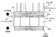
- FIG. 2 is a diagram showing a schematic configuration of the stator of this embodiment.
- the segment coil 20 is inserted in the axial direction from the end surface 22A on the anti-welding side of the stator core 22, and the coil of the portion protruding to the end surface 22B on the welding side on the opposite side is bent in the circumferential direction by TIG welding or the like. Connect to form a wave.
- the coil end portion 28 is formed between the end surface 22A on the anti-welding side and the tip of the hairpin portion 23 of the segment coil 20.
- the lead wire 21 of the coil is connected to the inverter control unit 12.
- FIG. 3 is a diagram showing the segment coil 20 of this embodiment.
- the segment coil 20 has slot insertion portions 24 to be inserted into the slots of the stator core 22 on both ends, and is formed in a substantially U-shape by hairpin portions 23 provided with one or more bending points connecting them.
- the flat wire constituting the segment coil 20 forms a covering region in the hairpin portion 23 and the slot insertion portion 24 which is covered with an insulator such as enamel, and the tip thereof is peeled off for welding and the mother. Copper, which is a material, forms an exposed area.
- the segment coil 20 is inserted into the stator core 22 and bent in the circumferential direction at a portion protruding from the stator core 22 to form a bent portion 20B.
- the area between the hairpin portion 23 and the bent portion 20B of the segment coil 20 is a covering region covered with an insulator, and the portion between the ends beyond the bent portion 20B is an exposed region. That is, the exposed region is provided at a portion where the two segment coils 20 (first coil 210 and second coil 220) are substantially parallel and adjacent to each other.
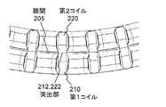
- FIG. 4 is a partial plan view of the stator core 22 equipped with the segment coil 20 as viewed from the welding side
- FIG. 5 is a perspective view of the stator core 22 equipped with the segment coil 20 on the welding side
- FIG. 6 is a segment. It is a perspective view of the tip portion of the coil 20.
- the segment coil 20 (first coil 210, second coil 220) is bent in the circumferential direction at a portion protruding from the stator core 22 to form a bent portion 20B.
- the first coil 210 and the second coil 220 project in a direction facing each other, and a protrusion 212 or 222 wider than the covering region is formed.
- the protruding portions 212 and 222 are provided at a portion where the first coil 210 and the second coil 220 to be welded at the tip portion are substantially parallel to each other and face each other.
- the first coil 210 and the second coil 220 form a welded portion 201 when the plane formed on the protrusion 212 and the plane formed on the protrusion 222 come into contact with each other.
- the protruding portion 212 and the protruding portion 222 are welded at the welded portion 201 which is the boundary surface thereof, and the first coil 210 and the second coil 220 are electrically connected to form a magnetic circuit.
- a gap 205 is formed in the covering region between the first coil 210 and the second coil 220 in a state of being aligned with the slots of the stator core 22. Therefore, the gap 205 can secure the insulation distance between the first coil 210 and the second coil 220, and even if the coating is damaged in the coating region, a short circuit between phases can be prevented.
- removal portions 213 and 223 from which the base material is removed so as to narrow the width of the exposed region are formed. That is, the base material on the opposite side of the position where the first coil 210 and the second coil 220 come into contact with each other is removed, and the steps 214 and 224 form the removing portions 213 and 223.
- the shape of the removal portions 213 and 223 is not limited to the step shape shown in the figure, and even if a slope is formed on the side surface of the exposed region and the removal portions 213 and 223 are formed so that the width becomes narrower toward the tip of the exposed region. Good.
- the side surface on the opposite side of the protruding portion 212 and 222 may be formed in the same shape as the protruding portion side.
- the removal portions 213 and 223 remove the base material on the tip end side of the exposed region in the width direction to form the tip end side of the exposed region to be narrower or the same width as the covering region, thereby forming the exposed region.
- the copper of the base material can be exposed on the opposite side of the protrusions 212 and 222, and the electrodes can be brought into contact with each other as a ground to which a current is applied during welding.
- 7, 8 and 9 are views showing the tip of the process of manufacturing the segment coil 20 of this embodiment.
- the bent segment coil 20 is press-processed to form a flat line having two sides facing each other in the cross section, and the tip portion is strongly pressed. To create a wide tip. Further, the press working for forming the flat line and the press working for widening the tip portion may be performed at the same time. By applying pressure to the segment coil 20 during press working, the hardness of the base material in the peeled region can be improved, deformation of the protrusions 212 and 222 can be prevented during welding, and the first coil 210 and the second coil 220 can be reliably secured. Can be welded. Further, the segment coil 20 may be formed by bending an already processed flat wire and pressing the tip. In this case, the tip of the segment coil 20 with a bent flat wire is pressed to create a wide tip.
- the insulating film on the surface of the exposed area is removed. Specifically, the regions (side surfaces of the exposed region) shown by hatching in FIGS. 8 and 9 are removed, and the coatings on the front and back surfaces of the exposed region are removed to remove the protrusions 212 and 222 and the removal portions 213 and 223.
- the tip portion may be removed by cutting by pressing or by cutting. By removing a part of the tip portion, the tip portion having the shape shown in FIG. 4 is formed. Either the step of removing the side surface of the exposed region and the step of removing the front surface and the back surface may be performed first.
- Either step 1 of bending the segment coil 20 or steps 2 to 3 of forming the protrusions 212 and 222 may be performed first.
- a plurality of segment coils 20 including a first coil 210 and a second coil 220 arranged adjacent to each other and a segment coil 20 are arranged.
- Each segment coil 20 has a coated portion (covered region) covered with an insulator and an exposed portion (exposed region) in which a conductor is exposed, and includes a core portion (stator core 22) having a space to be formed. Projecting portions 212 and 222 protruding from the side surface of the covering portion are formed in the exposed portion, and the protruding portion 212 of the first coil 210 and the protruding portion 222 of the second coil 220 are in surface contact with each other.
- the covering portion of the first coil 210 is arranged with a gap 205 from the covering portion of the second coil 220. Therefore, the protrusions 212 and 222 are in close contact with each other without bending so that the welded surfaces of the segment coils 20 come close to each other, and the first coil 210 and the second coil 220 can be connected by welding. Further, in a state where the covering region is in contact with each other due to bending, a phase-to-phase short circuit may occur due to damage to the insulating coating, but in this embodiment, the protruding portions 212 and 222 of the exposed region protrude from the covering region. In other parts (for example, the covering region), the segment coil 20 can be arranged on the stator core 22 so that a gap 205 is provided between the adjacent segment coils 20, and a short circuit between phases can be prevented.
- the protruding portions 212 and 222 are formed in the portions where the first coil 210 and the second coil 220 are arranged in parallel, the adhesion of the protruding portions 212 and 222 is improved and stable welding can be performed.
- the exposed portion is formed by removing the insulator by cutting the wire rod constituting the segment coil 20, the exposed portion can be accurately formed in a short time.
- removal portions 213 and 223 are provided on the opposite side of the protruding portions 212 and 222, and the exposed portion is formed in the removal portions 213 and 223 to be narrower or the same as the width of the covering portion. Therefore, the heat capacity of the welded portion 201 of the segment coil 20 can be reduced, and the first coil 210 and the second coil 220 can be reliably welded even with a small amount of heat.
- the method for manufacturing the stator of the rotary electric machine includes the procedure 1 of pressing so that the tip of the flat wire having at least a part of the side surface formed flat is wide, and the press working. Steps 2 to 3 for forming the projecting portions 212 and 222 having a flat surface protruding from the side surface of the flat wire on the side surface of the tip portion, and the segment coil 20 on which the projecting portions 212 and 222 are formed are arranged on the stator core 22. Since the procedure 4 for forming the winding is included, the exposed portion can be accurately formed in a short time in a simple step.
- the surface insulator is removed by cutting the side surface of the pressed tip to form the protrusions 212 and 222, so that the protrusions 212 and 222 are formed in a short time.
- the exposed part can be formed accurately.
- the present invention is not limited to the above-mentioned examples, but includes various modifications and equivalent configurations within the scope of the attached claims.
- the above-described examples have been described in detail in order to explain the present invention in an easy-to-understand manner, and the present invention is not necessarily limited to those having all the described configurations.
- a part of the configuration of one embodiment may be replaced with the configuration of another embodiment.
- the configuration of another embodiment may be added to the configuration of one embodiment.
- other configurations may be added / deleted / replaced with respect to a part of the configurations of each embodiment.
- Rotating electric machine assembly 11 Rotating electric machine 12 Inverter control unit 20 Segment coil 20B Bending part 21 Heading wire 22 Stator core 22A, 22B End face 23 Hairpin part 24 Slot insertion part 28 Coil end part 201 Welding part 205 Gap 210 First coil 220 Second Coil 212, 222 Protruding part 213, 223 Removal part 214, 224 Step
Landscapes
- Engineering & Computer Science (AREA)
- Power Engineering (AREA)
- Manufacturing & Machinery (AREA)
- Manufacture Of Motors, Generators (AREA)
- Windings For Motors And Generators (AREA)
Abstract
La présente invention a pour objet de fournir une bobine de stator dont les parties de soudage sont en contact étroit les unes avec les autres et dont les autres parties sont espacées les unes des autres. Le stator de machine électrique rotative comprend : une pluralité de bobines de segment comportant une première bobine et une seconde bobine qui sont disposées adjacentes l'une à l'autre ; et une partie centrale contenant un espace logeant les bobines de segment. Les bobines de segment possèdent chacune une partie couverte recouverte d'un isolant et une partie exposée dans laquelle est exposé un conducteur. La partie exposée est pourvue d'une partie en saillie faisant saillie à partir de la surface latérale de la partie couverte. Les parties en saillie des première et seconde bobines établissent un contact de surface l'une avec l'autre. La partie couverte de la première bobine est disposée à distance de la partie couverte de la seconde bobine.
Applications Claiming Priority (2)
| Application Number | Priority Date | Filing Date | Title |
|---|---|---|---|
| JP2019-057201 | 2019-03-25 | ||
| JP2019057201A JP2022078367A (ja) | 2019-03-25 | 2019-03-25 | 回転電機の固定子及びその製造方法 |
Publications (1)
| Publication Number | Publication Date |
|---|---|
| WO2020195069A1 true WO2020195069A1 (fr) | 2020-10-01 |
Family
ID=72609742
Family Applications (1)
| Application Number | Title | Priority Date | Filing Date |
|---|---|---|---|
| PCT/JP2020/002246 Ceased WO2020195069A1 (fr) | 2019-03-25 | 2020-01-23 | Stator de machine électrique rotative et son procédé de fabrication |
Country Status (2)
| Country | Link |
|---|---|
| JP (1) | JP2022078367A (fr) |
| WO (1) | WO2020195069A1 (fr) |
Cited By (1)
| Publication number | Priority date | Publication date | Assignee | Title |
|---|---|---|---|---|
| JP2022152174A (ja) * | 2021-03-29 | 2022-10-12 | 本田技研工業株式会社 | ステータ及びステータの製造方法 |
Citations (2)
| Publication number | Priority date | Publication date | Assignee | Title |
|---|---|---|---|---|
| JP4654068B2 (ja) * | 2005-05-24 | 2011-03-16 | 日立オートモティブシステムズ株式会社 | 接合電線と接合電線の加工方法,回転電機の固定子と回転電機の固定子の製造方法及び接合電線製造装置 |
| JP2018534901A (ja) * | 2016-03-08 | 2018-11-22 | 日立オートモティブシステムズ株式会社 | 回転電機 |
-
2019
- 2019-03-25 JP JP2019057201A patent/JP2022078367A/ja active Pending
-
2020
- 2020-01-23 WO PCT/JP2020/002246 patent/WO2020195069A1/fr not_active Ceased
Patent Citations (2)
| Publication number | Priority date | Publication date | Assignee | Title |
|---|---|---|---|---|
| JP4654068B2 (ja) * | 2005-05-24 | 2011-03-16 | 日立オートモティブシステムズ株式会社 | 接合電線と接合電線の加工方法,回転電機の固定子と回転電機の固定子の製造方法及び接合電線製造装置 |
| JP2018534901A (ja) * | 2016-03-08 | 2018-11-22 | 日立オートモティブシステムズ株式会社 | 回転電機 |
Cited By (2)
| Publication number | Priority date | Publication date | Assignee | Title |
|---|---|---|---|---|
| JP2022152174A (ja) * | 2021-03-29 | 2022-10-12 | 本田技研工業株式会社 | ステータ及びステータの製造方法 |
| JP7190524B2 (ja) | 2021-03-29 | 2022-12-15 | 本田技研工業株式会社 | ステータ及びステータの製造方法 |
Also Published As
| Publication number | Publication date |
|---|---|
| JP2022078367A (ja) | 2022-05-25 |
Similar Documents
| Publication | Publication Date | Title |
|---|---|---|
| JP7003674B2 (ja) | 回転電機のステータおよびステータコイルの製造方法 | |
| JP5804095B2 (ja) | ステータ及びステータの製造方法 | |
| CN112202262B (zh) | 配电部件 | |
| US20150022045A1 (en) | Electrical Rotating Machine | |
| CN109983656B (zh) | 内燃机用旋转电机及其定子 | |
| JPWO2020100311A1 (ja) | 固定子の製造方法 | |
| JP7000134B2 (ja) | ステータコイル、及び、そのリード部の形成方法 | |
| JP5237767B2 (ja) | 整流子及び該整流子を備える電機子及びモータ並びに該電機子の製造方法及びモータの製造方法 | |
| CN113439380B (zh) | 通过压合连接实现的定子连接端在pcb上的电接通 | |
| JP7146137B2 (ja) | 固定子 | |
| WO2018062351A1 (fr) | Moteur | |
| JP2019118200A (ja) | 導体接合方法 | |
| JP2022078367A (ja) | 回転電機の固定子及びその製造方法 | |
| JP2022049171A (ja) | 回転電機および回転電機の製造方法 | |
| WO2021210326A1 (fr) | Module de borne d'une machine électrique tournante | |
| JP6846391B2 (ja) | 電線セグメント及びステータ | |
| CN108370189A (zh) | 定子、旋转电机以及定子的制造方法 | |
| CN113950788B (zh) | 旋转电机 | |
| JPH1155879A (ja) | 電動機 | |
| JP2002369453A (ja) | 回転電機の整流子 | |
| WO2015025653A1 (fr) | Machine électrique tournante et procédé de fabrication d'une machine électrique tournante | |
| JP7318514B2 (ja) | 回転電機 | |
| CN118318373A (zh) | 用于旋转电机的有源部分的绕组的成型导体、旋转电机的有源部分和相关联的生产方法 | |
| JPWO2020250600A5 (fr) | ||
| JP6863167B2 (ja) | 回転電機ステータ |
Legal Events
| Date | Code | Title | Description |
|---|---|---|---|
| 121 | Ep: the epo has been informed by wipo that ep was designated in this application |
Ref document number: 20778527 Country of ref document: EP Kind code of ref document: A1 |
|
| NENP | Non-entry into the national phase |
Ref country code: DE |
|
| 122 | Ep: pct application non-entry in european phase |
Ref document number: 20778527 Country of ref document: EP Kind code of ref document: A1 |
|
| NENP | Non-entry into the national phase |
Ref country code: JP |