WO2020195320A1 - Soupape de régulation - Google Patents
Soupape de régulation Download PDFInfo
- Publication number
- WO2020195320A1 WO2020195320A1 PCT/JP2020/006017 JP2020006017W WO2020195320A1 WO 2020195320 A1 WO2020195320 A1 WO 2020195320A1 JP 2020006017 W JP2020006017 W JP 2020006017W WO 2020195320 A1 WO2020195320 A1 WO 2020195320A1
- Authority
- WO
- WIPO (PCT)
- Prior art keywords
- cylinder member
- seal cylinder
- valve
- region
- peripheral surface
- Prior art date
- Legal status (The legal status is an assumption and is not a legal conclusion. Google has not performed a legal analysis and makes no representation as to the accuracy of the status listed.)
- Ceased
Links
Images






Classifications
-
- F—MECHANICAL ENGINEERING; LIGHTING; HEATING; WEAPONS; BLASTING
- F01—MACHINES OR ENGINES IN GENERAL; ENGINE PLANTS IN GENERAL; STEAM ENGINES
- F01P—COOLING OF MACHINES OR ENGINES IN GENERAL; COOLING OF INTERNAL-COMBUSTION ENGINES
- F01P7/00—Controlling of coolant flow
- F01P7/14—Controlling of coolant flow the coolant being liquid
- F01P7/16—Controlling of coolant flow the coolant being liquid by thermostatic control
-
- F—MECHANICAL ENGINEERING; LIGHTING; HEATING; WEAPONS; BLASTING
- F16—ENGINEERING ELEMENTS AND UNITS; GENERAL MEASURES FOR PRODUCING AND MAINTAINING EFFECTIVE FUNCTIONING OF MACHINES OR INSTALLATIONS; THERMAL INSULATION IN GENERAL
- F16K—VALVES; TAPS; COCKS; ACTUATING-FLOATS; DEVICES FOR VENTING OR AERATING
- F16K39/00—Devices for relieving the pressure on the sealing faces
- F16K39/06—Devices for relieving the pressure on the sealing faces for taps or cocks
-
- F—MECHANICAL ENGINEERING; LIGHTING; HEATING; WEAPONS; BLASTING
- F16—ENGINEERING ELEMENTS AND UNITS; GENERAL MEASURES FOR PRODUCING AND MAINTAINING EFFECTIVE FUNCTIONING OF MACHINES OR INSTALLATIONS; THERMAL INSULATION IN GENERAL
- F16K—VALVES; TAPS; COCKS; ACTUATING-FLOATS; DEVICES FOR VENTING OR AERATING
- F16K5/00—Plug valves; Taps or cocks comprising only cut-off apparatus having at least one of the sealing faces shaped as a more or less complete surface of a solid of revolution, the opening and closing movement being predominantly rotary
- F16K5/04—Plug valves; Taps or cocks comprising only cut-off apparatus having at least one of the sealing faces shaped as a more or less complete surface of a solid of revolution, the opening and closing movement being predominantly rotary with plugs having cylindrical surfaces; Packings therefor
Definitions
- the present invention relates to a control valve used for switching the flow path of cooling water for a vehicle.
- the present application claims priority based on Japanese Patent Application No. 2019-060919 filed on March 27, 2019, the contents of which are incorporated herein by reference.
- a bypass flow path that bypasses the radiator and a warm air flow path that passes through the oil warmer are installed side by side.
- a control valve is interposed at a branch portion of the flow path, and the flow path is appropriately switched by the control valve.
- a control valve a cylindrical valve body is rotatably arranged in a casing, and an arbitrary flow path is opened and closed according to the rotation position of the valve body (see, for example, Patent Document 1). ..
- the control valve described in Patent Document 1 is provided with an inflow port into which a liquid such as cooling water flows in and a plurality of outflow ports from which the inflowing liquid flows out to the outside in a casing.
- a plurality of valve holes communicating inside and outside are formed on the peripheral wall of the valve body corresponding to a plurality of outlets.
- At each outlet one end side of a substantially cylindrical seal cylinder member is slidably held.
- One end of each seal tube member communicates with the downstream side of the corresponding outlet.
- a valve slide contact surface that slidably contacts the outer peripheral surface of the valve body is provided.
- each seal cylinder member is in sliding contact with the outer peripheral surface of the valve body at a position where it wraps with the rotation path of the corresponding valve hole of the valve body.
- the valve sliding contact surface of the seal cylinder member is formed so as to follow the outer surface shape of the valve body because it is in close contact with the outer peripheral surface of the valve body. That is, at the other end of the seal cylinder member in the axial direction, the protrusion height in the valve body direction continuously changes in the circumferential direction of the seal cylinder member so as to follow the outer surface shape of the valve body.
- valve body of the control valve When the valve body of the control valve is in a position where the seal cylinder member communicates with the corresponding valve hole, the valve body allows the liquid to flow out from the inner region of the valve body to the corresponding outlet, and the seal cylinder member corresponds to the valve. When in a position that does not communicate with the hole, it blocks the outflow of liquid from the inner region of the valve body to the corresponding outlet.
- the rotation position of the valve body is controlled by an actuator such as an electric motor.
- the protruding height of the other end of the seal cylinder member is continuously changed so as to follow the outer surface shape of the cylindrical valve body. Therefore, in the region where the protrusion height is high in the other end of the seal cylinder member, when the pressure of the liquid in the casing acts on the outer peripheral surface near the protrusion end, the pressure acts on the other end side of the seal cylinder member. It works as a moment to bend and deform. Specifically, when the pressure of the liquid in the casing acts on the outer peripheral surface near the protruding end in the region where the protruding height of the other end of the seal cylinder member is high, the force caused by the pressure acting on the outer peripheral surface.
- the problem to be solved is to suppress the deformation of the seal cylinder member due to the hydraulic pressure in the casing and improve the seal performance between the seal cylinder member and the valve body.
- the control valve of one embodiment of the present invention is rotatably arranged inside and outside a casing having an inflow port where a liquid flows in from the outside and an outflow port where the liquid flowing into the inside flows out to the outside.
- a valve body having a peripheral wall portion on which a valve hole for communicating with the valve body is formed, and one end portion in the axial direction communicate with the outlet, and the other end portion in the axial direction is a rotation path of the valve hole of the valve body.
- a seal cylinder member provided with a valve sliding contact surface that slidably contacts the outer peripheral surface of the peripheral wall portion at a position where at least a part of the seal cylinder member wraps, and the other end portion of the seal cylinder member in the axial direction is provided.
- the protrusion height of the other end portion of the seal cylinder member In a control valve in which the protrusion height in the direction toward the peripheral wall portion continuously changes in the circumferential direction along the shape of the outer peripheral surface of the peripheral wall portion, the protrusion height of the other end portion of the seal cylinder member. It is characterized in that a small outer diameter portion whose length from the axial center to the outer peripheral surface of the seal cylinder member is shorter than that of other regions is provided in the high region.
- the pressure of the liquid in the casing acts on the outer periphery of the other end of the seal cylinder member.
- a force due to the pressure of the liquid in the casing acts on the outer peripheral surface near the protruding end.
- This force acts on the other end side of the seal cylinder member as a moment starting from a region having a low protrusion height.
- the pressure receiving surface small outside in the region where the protruding height is high. The distance from the diameter part) to the starting point of the moment becomes shorter. As a result, the moment acting on the other end of the seal cylinder member becomes small, and the bending deformation of the other end of the seal cylinder member due to the moment is suppressed.
- the small outer diameter portion may be formed by a first plane whose end on the valve sliding contact surface side forms a linear shape substantially parallel to the rotation axis of the valve body.
- a second plane substantially parallel to the first plane is formed on the inner peripheral surface of the other end of the seal cylinder member in a region having a high protrusion height so as to bulge inward in the radial direction of the seal cylinder member. It may be done.
- the radial width (thickness) of the region where the protruding height of the other end of the seal cylinder member is high can be made substantially constant, the surface pressure increases due to the decrease in the radial width of the valve slide contact surface. Can be suppressed. As a result, it becomes possible to further suppress the wear of the other end of the seal cylinder member.
- the seal cylinder member is located on the one end side and is located on the other end side of the first cylinder portion that communicates with the outlet, and the end surface in the axial direction constitutes the valve slide contact surface.
- the inner peripheral surface has a second cylinder portion formed by bulging the second plane, and the inner diameter of the first cylinder portion is formed to be smaller than the inner diameter of the second cylinder portion. Is also good.
- the flow rate of the liquid flowing out to the downstream side of the outlet through the seal cylinder member is determined by the inner diameter of the first cylinder portion of the seal cylinder member having a relatively small inner diameter. Since the second plane formed by bulging toward the inner peripheral side is provided inside the second cylinder having a relatively large inner diameter in the radial direction, it affects the flow rate of the liquid flowing out to the downstream side of the outlet. Do not give. Therefore, when this configuration is adopted, the flow rate of the liquid flowing out to the outlet can be easily set and adjusted.
- the outer peripheral surface of the other end of the seal cylinder member may be formed in a substantially elliptical shape in which the region having the highest protruding height has a minor diameter and the region having the lowest protruding height has a major diameter.
- the radial width of the other end of the seal cylinder member may be formed to be a constant width in the peripheral region of the seal cylinder member.
- the seal cylinder member is located on the one end side and is located on the other end side of the first cylinder portion which communicates with the outlet, and the axial end surface constitutes the valve slide contact surface.
- the outer peripheral surface and the inner peripheral surface of the second tubular portion have a tubular portion and have a substantially elliptical shape in which the region having the highest protruding height has a minor diameter and the region having the lowest protruding height has a major diameter.
- the inner peripheral surface of the second cylinder portion having the highest protruding height may be continuously formed on the inner peripheral surface of the first cylinder portion without a step.
- the radial width of the region having a low protrusion height at the other end may be formed wider than the radial width of the region having a high protrusion height at the other end.
- the radial width of the region of the other end of the seal cylinder member having a low protrusion height where the Hertz surface pressure tends to increase is formed to be wide, the surface pressure at the portion having a low protrusion height is formed. Can be suppressed from increasing. Therefore, it is possible to suppress premature wear of the other end of the seal cylinder member, which has a low protrusion height.
- the control valve described above has a small outer diameter in a region of the other end of the seal cylinder member having a high protrusion height, in which the length from the axial center to the outer peripheral surface of the seal cylinder member is shorter than in other regions. Since the portion is provided, it is possible to suppress the generation of a moment due to the hydraulic pressure received on the outer peripheral surface of the region having a high protrusion height, and to suppress the bending deformation of the other end portion of the seal cylinder member. Therefore, when the above-mentioned control valve is adopted, the sealing performance between the seal cylinder member and the valve body can be improved.
- FIG. 1 is a block diagram of the cooling system 1. As shown in FIG. 1, the cooling system 1 is mounted on a vehicle having at least an engine as a vehicle drive source.
- the vehicle may be a hybrid vehicle, a plug-in hybrid vehicle, or the like, in addition to a vehicle having only an engine.
- the cooling system 1 includes an engine 2 (ENG), a water pump 3 (W / P), a radiator 4 (RAD), a heat exchanger 5 (H / EX), a heater core 6 (HTR), an EGR cooler 7 (EGR), and a control.
- the valve 8 (EWV) is connected by various flow paths 10 to 14.
- the water pump 3, the engine 2, and the control valve 8 are sequentially connected on the main flow path 10 from upstream to downstream. In the main flow path 10, the cooling water (liquid) passes through the engine 2 and the control valve 8 in order by the operation of the water pump 3.
- the radiator flow path 11, the warm-up flow path 12, the air conditioning flow path 13, and the EGR flow path 14 are connected to the main flow path 10, respectively.
- the radiator flow path 11, the warm-up flow path 12, the air conditioning flow path 13, and the EGR flow path 14 connect the upstream portion of the water pump 3 and the control valve 8 of the main flow path 10.
- the radiator 4 is connected to the radiator flow path 11. In the radiator flow path 11, heat exchange between the cooling water and the outside air is performed in the radiator 4.
- a heat exchanger 5 is connected to the warm-up flow path 12.
- Engine oil circulates between the heat exchanger 5 and the engine 2 through an oil flow path 18.
- heat exchanger 5 heat exchange between the cooling water and the engine oil is performed in the heat exchanger 5. That is, the heat exchanger 5 functions as an oil warmer when the water temperature is higher than the oil temperature and heats the engine oil.
- the heat exchanger 5 functions as an oil cooler when the water temperature is lower than the oil temperature and cools the engine oil.
- the heater core 6 is connected to the air conditioning flow path 13.
- the heater core 6 is provided, for example, in a duct (not shown) of an air conditioner.
- heat exchange between the cooling water and the air conditioning air flowing in the duct is performed in the heater core 6.
- the EGR cooler 7 is connected to the EGR flow path 14. In the EGR flow path 14, heat exchange between the cooling water and the EGR gas is performed in the EGR cooler 7.
- the cooling water that has passed through the engine 2 in the main flow path 10 flows into the control valve 8 and then is selectively distributed to the various flow paths 11 to 13 by the operation of the control valve 8.
- early temperature rise and high water temperature (optimal temperature) control can be realized, and the fuel efficiency of the vehicle is improved.
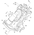
- FIG. 2 is a perspective view of the control valve 8 of the first embodiment.
- FIG. 3 is an exploded perspective view of the control valve 8.
- the control valve 8 mainly includes a casing 21, a valve body 22 (see FIG. 3), and a drive unit 23.
- the casing 21 has a bottomed tubular casing main body 25 and a lid 26 that closes the opening of the casing main body 25.
- the direction along the axis O1 of the casing 21 is simply referred to as the case axial direction.
- the direction toward the bottom wall 32 of the casing body 25 with respect to the case peripheral wall 31 of the casing body 25 is referred to as the first side
- the direction toward the lid 26 with respect to the case peripheral wall 31 of the casing body 25 is referred to as the first side. It is called the second side.
- the direction orthogonal to the axis O1 is referred to as the case radial direction
- the direction around the axis O1 is referred to as the case circumferential direction.
- a plurality of mounting pieces 33 are formed on the case peripheral wall 31 of the casing main body 25. Each mounting piece 33 projects from the case peripheral wall 31 to the outside in the case radial direction.
- the control valve 8 is fixed in the engine chamber via, for example, each mounting piece 33. The position and number of the mounting pieces 33 can be changed as appropriate.
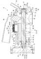
- FIG. 4 is a cross-sectional view taken along the line IV-IV of FIG.
- an inflow port 37 that bulges outward in the radial direction of the case is formed in a portion of the case peripheral wall 31 located on the second side.
- the inflow port 37 is formed with an inflow port 37a (see FIG. 4) that penetrates the inflow port 37 in the radial direction of the case.
- the inflow port 37a communicates with the inside and outside of the casing 21.
- the above-mentioned main flow path 10 (see FIG. 1) is connected to the open end surface (outer end surface in the case radial direction) of the inflow port 37.
- a radiator port 41 that bulges outward in the case radial direction is formed at a position of the case peripheral wall 31 that faces the inflow port 37 with the axis O1 in between in the case radial direction. ..
- the radiator port 41 is formed with a fail opening 41a and a radiator outlet 41b (outlet) arranged side by side in the case axial direction.
- the fail opening 41a and the radiator outlet 41b each penetrate the radiator port 41 in the radial direction of the case.
- the fail opening 41a faces the above-mentioned inflow port 37a in the case radial direction.
- the radiator outlet 41b is located on the first side in the case axial direction with respect to the fail opening 41a.
- the radiator joint 42 is connected to the open end surface (outer end surface in the radial direction of the case) of the radiator port 41.
- the radiator joint 42 connects the radiator port 41 and the upstream end of the radiator flow path 11 (see FIG. 1).
- the radiator joint 42 is welded (for example, vibration welding or the like) to the open end surface of the radiator port 41.
- a thermostat 45 is provided in the fail opening 41a.
- the thermostat 45 faces the above-mentioned inflow port 37a in the case radial direction.
- the thermostat 45 opens and closes the fail opening 41a according to the temperature of the cooling water flowing in the casing 21.
- An EGR outlet 51 is formed in a portion of the lid 26 located closer to the radiator port 41 in the case radial direction with respect to the axis O1.
- the EGR outlet 51 penetrates the lid 26 in the case axial direction.
- the EGR outlet 51 intersects (orthogonally) the opening direction (case radial direction) of the fail opening 41a. Further, at least a part of the EGR outlet 51 overlaps with the thermostat 45 when viewed from the front in the case axial direction.
- an EGR joint 52 is formed at the opening edge of the EGR outlet 51.
- the EGR joint 52 is formed in a tubular shape extending outward in the radial direction of the case toward the second side in the axial direction of the case, and is between the EGR outlet 51 and the upstream end of the EGR flow path 14 (see FIG. 1) described above. Is connected.
- a warm-up port 56 that bulges outward in the case radial direction is formed in a portion of the case peripheral wall 31 that is located on the first side in the case axial direction with respect to the radiator port 41.
- the warm-up port 56 is formed with a warm-up outlet 56a (outlet) that penetrates the warm-up port 56 in the radial direction of the case.
- a warm-up joint 62 is connected to the open end face of the warm-up port 56.
- the warm-up joint 62 connects the warm-up port 56 and the upstream end of the warm-up flow path 12 (see FIG. 1) described above.
- the warm-up joint 62 is welded (for example, vibration welding) to the open end surface of the warm-up port 56.
- An air conditioning port 66 is formed at the displaced position.
- the air conditioning port 66 is formed with an air conditioning outlet 66a (outlet) that penetrates the air conditioning port 66 in the radial direction of the case.
- An air conditioning joint 68 is connected to the open end surface of the air conditioning port 66.
- the air conditioning joint 68 connects the air conditioning port 66 and the upstream end of the air conditioning flow path 13 (see FIG. 1) described above.
- the air conditioning joint 68 is welded (for example, vibration welding) to the open end surface of the air conditioning port 66.
- the drive unit 23 is attached to the bottom wall portion 32 of the casing main body 25.
- a motor, a speed reduction mechanism, a control board, and the like are housed in a unit case.
- the valve body 22 is housed in the casing 21.
- the valve body 22 is formed in a cylindrical shape, and is arranged coaxially with the axis O1 of the casing 21 inside the casing 21.
- the valve body 22 opens and closes each of the above-mentioned outlets (radiator outlet 41b, warm-up outlet 56a, and air-conditioning outlet 66a) by rotating around the axis O1.
- valve body 22 is configured such that the inner shaft portion 73 is insert-molded inside the rotor main body 72.
- the inner shaft portion 73 extends coaxially with the axis O1.
- the first side end of the inner shaft portion 73 penetrates the bottom wall portion 32 in the case axial direction through the through hole (open to the atmosphere) 32a formed in the bottom wall portion 32.
- the first side end portion of the inner shaft portion 73 is rotatably supported by the first bush (first bearing) 78 provided on the bottom wall portion 32 described above.
- the bottom wall portion 32 is formed with a first shaft accommodating wall 79 toward the second side in the case axial direction.
- the first shaft accommodating wall 79 surrounds the above-mentioned through hole 32a.
- the above-mentioned first bush 78 is fitted inside the first shaft accommodating wall 79.
- a connecting portion 73a is formed in a portion of the inner shaft portion 73 located on the first side in the case axial direction with respect to the first bush 78 (a portion located outside the bottom wall portion 32).
- the connecting portion 73a is connected to the drive unit 23 described above outside the casing 21. As a result, the power of the drive unit 23 is transmitted to the inner shaft portion 73.
- the second side end of the inner shaft portion 73 is rotatably supported by the second bush (second bearing) 84 provided on the lid body 26 described above.
- the lid 26 is formed with a second shaft accommodating wall 86 toward the first side in the case axial direction.
- the second shaft accommodating wall 86 surrounds the axis O1 inside the case radial direction with respect to the above-mentioned EGR outlet 51.
- the above-mentioned second bush 84 is fitted inside the second shaft accommodating wall 86.
- the rotor body 72 surrounds the inner shaft portion 73 described above.
- the rotor body 72 has an outer shaft portion 81 that covers the inner shaft portion 73, a peripheral wall portion 82 that surrounds the outer shaft portion 81, and spoke portions 83 that connect the outer shaft portion 81 and the peripheral wall portion 82. ..
- the outer shaft portion 81 surrounds the inner shaft portion 73 over the entire circumference in a state where both ends of the inner shaft portion 73 in the case axial direction are exposed.
- the outer shaft portion 81 and the inner shaft portion 73 constitute the rotating shaft 85 of the valve body 22.
- a first lip seal 87 is provided in a portion of the above-mentioned first shaft accommodating wall 79 located on the second side in the case axial direction with respect to the first bush 78.
- the first lip seal 87 seals between the inner peripheral surface of the first shaft accommodating wall 79 and the outer peripheral surface of the rotating shaft 85 (outer shaft portion 81).
- a portion of the first shaft accommodating wall 79 located on the first side in the case axial direction with respect to the first lip seal 87 is open to the atmosphere through the through hole 32a.
- a second lip seal 88 is provided at a portion located on the first side in the case axial direction with respect to the second bush 84.
- the second lip seal 88 seals between the inner peripheral surface of the second shaft accommodating wall 86 and the outer peripheral surface of the rotating shaft 85 (outer shaft portion 81).
- the lid body 26 is formed with a through hole (open to the atmosphere) 98 that penetrates the lid body 26 in the axial direction of the case.
- the peripheral wall portion 82 of the valve body 22 is arranged coaxially with the axis O1.
- the peripheral wall portion 82 is arranged in the casing 21 at a portion located on the first side in the case axial direction with respect to the inflow port 37a.
- the peripheral wall portion 82 is arranged at a position that avoids the fail opening 41a and straddles the radiator outlet 41b, the warm-up outlet 56a, and the air conditioning outlet 66a in the case axial direction.
- the inside of the peripheral wall portion 82 constitutes a flow passage 91 in which the cooling water flowing into the casing 21 through the inflow port 37a flows in the axial direction of the case.
- a portion located on the second side in the case axial direction with respect to the peripheral wall portion 82 constitutes a connecting flow path 92 communicating with the flow passage 91.
- a gap C2 is provided in the radial direction of the case between the outer peripheral surface of the peripheral wall portion 82 and the inner peripheral surface of the case peripheral wall 31.
- a valve hole 95 that penetrates the peripheral wall portion 82 in the case radial direction is formed at the same position in the case axial direction as the radiator outlet 41b described above.
- the valve hole 95 passes through the valve hole 95 into the peripheral wall portion 82 (flow passage 91) and the radiator outlet 41b. To communicate with.
- valve hole 96 that penetrates the peripheral wall portion 82 in the case radial direction is formed at the same position in the case axial direction as the warm-up outlet 56a described above.
- the valve hole 96 overlaps with the seal cylinder member 131 inserted into the warm-up outlet 56a when viewed from the case radial direction, the valve hole 96 passes through the valve hole 96 into the peripheral wall portion 82 (flow passage 91) and the warm-up flow. It communicates with the exit 56a.
- valve hole 97 that penetrates the peripheral wall portion 82 in the case radial direction is formed at the same position as the air conditioning outlet 66a described above in the case axial direction.
- the valve hole 97 overlaps with the seal cylinder member 131 inserted into the air conditioning outlet 66a when viewed from the case radial direction, the valve hole 97 enters the peripheral wall portion 82 (flow passage 91) and the air conditioning outlet 66a through the valve hole 97. To communicate with.
- the valve body 22 switches between communication and cutoff between the valve holes 95, 96, 97 and the corresponding outlets 41b, 56a, 66a as the valve body 22 rotates around the axis O1.
- the communication pattern between the valve holes 95, 96, 97 and the outlets 41b, 56a, 66a can be appropriately set.
- connection portion of the warm-up port 56 and the warm-up joint 62 will be described.
- the connection portion between the radiator port 41 and the radiator joint 42 and the connection portion between the air conditioning port 66 and the air conditioning joint 68 have the same configurations as the connection portions of the warm-up port 56 and the warm-up joint 62. Is omitted.
- FIG. 5 is an enlarged cross-sectional view corresponding to the VV line of FIG.
- the direction along the axis O2 of the warm-up outlet 56a may be referred to as the port axial direction (first direction).
- the direction toward the axis O1 with respect to the warm-up port 56 is referred to as the inside, and the direction away from the axis O1 with respect to the warm-up port 56 is referred to as the outside.
- the direction orthogonal to the axis O2 may be referred to as the port radial direction (second direction), and the direction around the axis O2 may be referred to as the port circumferential direction.
- the port radial direction second direction
- the direction around the axis O2 may be referred to as the port circumferential direction.
- the warm-up port 56 has a seal cylinder portion 101 extending in the port axial direction and a port flange portion 102 extending outward from the seal cylinder portion 101 in the port radial direction.
- the inside of the seal cylinder portion 101 constitutes the warm-up outlet 56a (outlet) described above.
- the inner diameter of the seal cylinder portion 101 is uniformly set in the region excluding the outer end portion in the port axial direction.
- a surrounding wall 105 protruding outward in the port axial direction is formed on the outer peripheral portion of the port flange portion 102.
- the surrounding wall 105 is formed over the entire circumference of the port flange portion 102.
- a port joint portion 106 projecting outward in the port axial direction is formed at a portion located inside the port radial direction with respect to the surrounding wall 105.
- the port joint 106 is formed over the entire circumference of the port flange 102.
- the warm-up joint 62 has a joint cylinder portion 110 arranged coaxially with the axis O2, and a joint flange portion 111 projecting from the inner end portion of the joint cylinder portion 110 in the port axial direction to the outside in the port radial direction. ing.
- the joint flange portion 111 is formed in an annular shape having an outer diameter equivalent to that of the port flange portion 102 and an inner diameter larger than the outer diameter of the seal cylinder portion 101.
- a joint joint 113 projecting inward in the port axial direction is formed on the inner peripheral portion of the joint flange 111.
- the joint joint 113 faces the port joint 106 in the port axial direction.
- the warm-up port 56 and the warm-up joint 62 are joined to each other by vibration-welding the facing surfaces of the port joint portion 106 and the joint joint portion 113 to each other.
- the joint cylinder portion 110 extends from the inner peripheral edge of the joint flange portion 111 to the outside in the port axial direction.
- the joint tubular portion 110 is formed in a multi-stage tubular shape whose diameter is gradually reduced toward the outside in the port axial direction. Specifically, in the joint cylinder portion 110, the large diameter portion 121, the medium diameter portion 122, and the small diameter portion 123 are sequentially connected to the outside in the port axial direction.
- the large diameter portion 121 surrounds the seal cylinder portion 101 in a state where the seal cylinder portion 101 is spaced outside in the port radial direction with respect to the seal cylinder portion 101 described above.
- the medium diameter portion 122 faces the seal cylinder portion 101 with a gap Q1 in the port axial direction.
- a seal mechanism 130 is provided in a portion surrounded by the warm-up port 56 and the warm-up joint 62.
- the seal mechanism 130 includes a seal cylinder member 131, an urging member 132, a seal ring 133, and a holder 134.
- a seal mechanism 130 having the same configuration as the seal mechanism 130 provided in the warm-up port 56 is also provided in the radiator port 41 and the air conditioning port 66 described above.
- the seal mechanism 130 provided in the radiator port 41 and the air conditioning port 66 is designated by the same reference numerals as the seal mechanism 130 provided in the warm-up port 56, and the description thereof will be omitted. ..
- the seal cylinder member 131 is inserted into the warm-up outlet 56a.
- the seal cylinder member 131 has a peripheral wall extending coaxially with the axis O2.
- the peripheral wall of the seal cylinder member 131 is formed in a multi-stage cylinder shape in which the outer diameter is gradually reduced toward the outside in the port axial direction.
- the peripheral wall of the seal cylinder member 131 is located on the outside in the port axial direction (one end side in the axial direction), and communicates with the first tubular portion 142 communicating with the downstream side of the warm-up outlet 56a and the port axial direction. It has a second tubular portion 141, which is located inside (the other end side in the axial direction) and has an inner diameter and an outer diameter larger than that of the first tubular portion 142.
- a large-diameter second cylinder portion 141 is slidably inserted into the inner peripheral surface of the seal cylinder portion 101.
- the inner end surface of the second tubular portion 141 in the port axial direction constitutes a valve sliding contact surface 141a that slidably contacts the outer peripheral surface of the peripheral wall portion 82 of the valve body 22.
- the valve sliding contact surface 141a is a curved surface formed according to the radius of curvature of the outer peripheral surface of the peripheral wall portion 82.
- the outer peripheral surface of the first tubular portion 142 is connected to the outer peripheral surface of the second tubular portion 141 via a stepped surface 143.
- the stepped surface 143 is inclined outward in the port radial direction toward the inside in the port axial direction, and then extends further outward in the port radial direction. Therefore, a seal gap Q2 is provided in the port radial direction between the outer peripheral surface of the small diameter first cylinder portion 142 and the inner peripheral surface of the seal cylinder portion 101.
- the outer end surface of the first cylinder portion 142 in the port axial direction (hereinafter referred to as "seat surface 142a") is a flat surface orthogonal to the port axial direction.
- the seat surface 142a of the first cylinder portion 142 is arranged at a position equivalent to the outer end surface of the seal cylinder portion 101 in the port axial direction.
- the seal cylinder member 131 is separated from the warm-up joint 62 in the port radial direction and the port axial direction.
- the urging member 132 is interposed between the seat surface 142a of the seal cylinder member 131 and the inner end surface of the small diameter portion 123 of the warm-up joint 62 in the port axial direction.
- the urging member 132 is, for example, a wave spring.
- the urging member 132 urges the seal cylinder member 131 inward in the port axial direction (toward the peripheral wall portion 82).
- the seal ring 133 is, for example, a Y packing.
- the seal ring 133 is extrapolated to the first cylinder portion 142 of the seal cylinder member 131 with the opening (forked portion) facing inward in the port axial direction. Specifically, in the state where the seal ring 133 is arranged in the seal gap Q2 described above, each tip of the bifurcated portion slides on the outer peripheral surface of the first cylinder portion 142 and the inner peripheral surface of the seal cylinder portion 101, respectively. Close to possible.
- the inner region in the port axial direction with respect to the seal ring 133 is cooled in the casing 21 through the gap between the inner peripheral surface of the seal cylinder portion 101 and the second cylinder portion 141 of the seal cylinder member 131.
- the hydraulic pressure of water is introduced.
- the stepped surface 143 is formed in a direction opposite to the valve sliding contact surface 141a of the seal cylinder member 131 in the port axial direction.
- the stepped surface 143 constitutes a pressure receiving surface that receives the hydraulic pressure of the cooling water in the casing 21 and is pressed inward in the port axial direction.
- FIG. 6 is an enlarged view of the VI portion of FIG.
- the area S1 of the stepped surface 143 and the area S2 of the valve sliding contact surface 141a are set so as to satisfy the following equations (1) and (2).
- ⁇ Lower limit value of the pressure reduction constant determined by the physical properties of the cooling water
- the area S2 between S1 and the valve sliding contact surface 141a means the area when projected in the port axial direction.
- the pressure reduction constant k in the equation (2) is a standard value of the pressure reduction constant when the valve slide contact surface 141a is uniformly in contact with the peripheral wall portion 82 from the outer edge to the inner edge in the port radial direction. It becomes ⁇ (for example, 1/2). However, due to manufacturing error, assembly error, etc.
- the gap between the outer peripheral portion of the valve slide contact surface 141a and the peripheral wall portion 82 slightly increases with respect to the inner peripheral portion of the valve slide contact surface 141a.
- the pressure of the cooling water decreases when the cooling water flows from the outer edge to the inner edge in the radial direction of the port through a minute gap between the valve sliding contact surface 141a and the peripheral wall portion 82. It works with it. At this time, the pressure of the cooling water gradually decreases toward the inside in the port radial direction, and tries to push up the seal cylinder member 131 to the outside in the port axial direction.
- the force obtained by multiplying the area S1 of the stepped surface 143 by the pressure P in the casing 21 acts as it is on the stepped surface 143 of the seal cylinder member 131.
- a force acting on the valve slide contact surface 141a of the seal cylinder member 131 by multiplying the area S2 of the valve slide contact surface 141a by the pressure P in the casing 21 and the pressure reduction constant k acts as it is on the stepped surface 143 of the seal cylinder member 131.
- the area S1 of the stepped surface 143 of the seal cylinder member 131 is smaller than the area S2 of the valve sliding contact surface 141a. Therefore, even if the pressure of the cooling water in the casing 21 increases, it is possible to prevent the valve sliding contact surface 141a of the seal cylinder member 131 from being pressed against the peripheral wall portion 82 by an excessive force. Therefore, when the control valve 8 of the present embodiment is adopted, it is possible to avoid increasing the size and output of the drive unit 23 that rotationally drives the valve body 22, and also the seal cylinder member 131 and each bush 78. Premature wear of 84 (see FIG. 4) can be suppressed.
- the valve does not fall below the inward pressing force acting on the seal cylinder member 131 in the port axial direction and the outward lifting force acting on the seal cylinder member 131 in the port axial direction.
- the area S2 of the sliding contact surface 141a is set to be larger than the area S1 of the stepped surface 143. Therefore, it is possible to seal between the seal cylinder member 131 and the peripheral wall portion 82 while suppressing the pressing of the seal cylinder member 131 against the peripheral wall portion 82 by an excessive force.
- the holder 134 described above is configured to be movable in the port axial direction with respect to the warm-up port 56 and the warm-up joint 62 in the gap Q1. Further, the holder 134 is arranged at least one of the warm-up port 56 and the warm-up joint 62 so as to be separated in the port axial direction.
- the holder 134 has a holder cylinder portion 151, a holder flange portion 152, and a regulation portion 153.
- the holder cylinder portion 151 extends in the port axial direction.
- the holder cylinder portion 151 is inserted into the seal gap Q2 from the outside in the port axial direction.
- the bottom portion of the seal ring 133 described above can be brought into contact with the inner end surface of the holder cylinder portion 151 in the port axial direction. That is, the holder cylinder portion 151 restricts the movement of the seal ring 133 to the outside in the port axial direction.
- the holder flange portion 152 projects from the outer end portion of the holder cylinder portion 151 in the port axial direction to the outer side in the port radial direction.
- the holder flange portion 152 is arranged in the gap Q1 between the outer end surface of the seal cylinder portion 101 in the port axial direction and the inner end surface of the medium diameter portion 122 in the port axial direction.
- the inward movement of the holder 134 in the port axial direction is regulated by the seal cylinder portion 101, and the outward movement of the holder 134 in the port axial direction is regulated by the medium diameter portion 122.
- the regulation portion 153 is formed so as to project in a tubular shape from the inner peripheral portion of the holder cylinder portion 151 to the outside in the port axial direction.
- the regulating unit 153 regulates the movement of the urging member 132 in the port radial direction together with the holder cylinder portion 151.
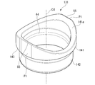
- FIG. 7 is a perspective view of the seal cylinder member 131 viewed with the valve sliding contact surface 141a side facing up.
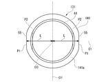
- FIG. 8 is an end view of the seal cylinder member 131 as viewed from the valve slide contact surface 141a side.
- the seal cylinder member 131 has a first cylinder portion 142 and a second cylinder portion 141 having an outer diameter larger than that of the first cylinder portion 142, and has an axial end portion (axial direction) of the second cylinder portion 141.
- the other end) is provided with a valve sliding contact surface 141a that slidably contacts the outer peripheral surface of the peripheral wall portion 82 of the valve body 22.
- a stepped surface 143 is provided between the outer peripheral surface of the first tubular portion 142 and the outer peripheral surface of the second tubular portion 141. Further, the inner diameter of the first cylinder portion 142 is formed to be smaller than the inner diameter of the second cylinder portion 141. A stepped surface 44 is provided between the inner peripheral surface of the first tubular portion 142 and the inner peripheral surface of the second tubular portion 141.
- the peripheral wall at the axial end (inner end in the port axial direction) of the second tubular portion 141 has a protruding height in the direction toward the peripheral wall portion 82 along the shape of the outer peripheral surface of the peripheral wall portion 82 of the valve body 22. Is continuously changing in the circumferential direction. That is, the protruding height of the peripheral wall at the axial end of the second tubular portion 141 is continuously changed so that the valve sliding contact surface 141a is in surface contact with the outer peripheral surface of the peripheral wall portion 82 of the valve body 22. There is.
- the axial end of the second tubular portion 141 has the lowest protruding height of the region located on the outermost side in the direction along the axis O1 (rotational axis of the valve body 22), and is orthogonal to the axis O1. With respect to (direction along the rotation direction of the valve body 22), the protruding height of the outermost region is the highest.
- Reference numeral C1 in FIG. 8 is a center line indicating the center of the valve holes 96 (95, 97) in the axis O1 direction of the valve body 22.
- the seal cylinder member 131 has a high protrusion height (hereinafter, referred to as "protrusion height in the valve body 22 direction") of the peripheral wall of the second cylinder portion 141 in the direction toward the peripheral wall portion 82 of the valve body 22.
- the length L from the axial center O3 of the seal cylinder member 131 to the outer peripheral surface is shorter in the two regions (two regions including the portion where the protrusion height in the valve body 22 direction is maximum) as compared with the other regions.
- a small outer diameter portion 55 is provided.
- the small outer diameter portion 55 is formed by a plane P1 (first plane) whose end on the valve sliding contact surface 141a side has a linear shape substantially parallel to the rotation axis (axis O1) of the valve body 22.
- the plane P1 extends parallel to the axial center O3 of the seal cylinder member 131.
- the inner peripheral surface of the second tubular portion 141 is formed in a circular shape having a constant length from the axial center O3 over the circumferential direction, but the inner peripheral surface of the second tubular portion 141 is formed.
- a second plane P2 (see FIG.
- substantially parallel to the plane P1 (first plane) is formed by bulging inward in the radial direction in a region of the peripheral surface having a high protrusion height in the valve body 22 direction. You may.
- the radial width of the second cylinder portion 141 can be made constant in the peripheral region of the seal cylinder member 131.
- connection flow path 92 Of the cooling water that has flowed into the connection flow path 92, some of the cooling water flows into the EGR outlet 51.
- the cooling water that has flowed into the EGR outlet 51 is supplied into the EGR flow path 14 through the EGR joint 52.
- the cooling water supplied into the EGR flow path 14 is returned to the main flow path 10 after heat exchange between the cooling water and the EGR gas is performed in the EGR cooler 7.
- the cooling water that has flowed into the connecting flow path 92 flows into the flow path 91 from the second side in the case axial direction.
- the cooling water that has flowed into the flow passage 91 is distributed to each outlet in the process of flowing through the flow passage 91 in the axial direction of the case. That is, the cooling water flowing into the flow passage 91 is distributed to the respective flow paths 11 to 13 through the outflow port communicating with the corresponding valve hole among the outflow ports.
- valve body 22 In the control valve 8, in order to switch the communication pattern between the valve hole and the outlet, the valve body 22 is rotated around the axis O1. Then, by stopping the rotation of the valve body 22 at a position corresponding to the communication pattern to be set, the valve hole and the outflow port communicate with each other in a communication pattern corresponding to the stop position of the valve body 22.
- the axial center of the seal cylinder member 131 is located in the region of the peripheral wall at the axial end of the seal cylinder member 131 where the protrusion height in the valve body 22 direction is high.
- a small outer diameter portion 55 having a shorter length from the O3 to the outer peripheral surface than other regions is provided. Therefore, when the seal cylinder member 131 is in a state of non-communication with the valve hole of the valve body 22, a region having a high protrusion height in the valve body 22 direction on the outer peripheral surface of the axial end portion of the seal cylinder member 131. Further, even if the hydraulic pressure in the casing 21 acts, it becomes difficult for a large moment to act on the seal cylinder member 131 starting from a region having a low protrusion height in the valve body 22 direction.
- the starting point of the moment (region having a low protrusion height) from the pressure receiving surface (small outer diameter portion 55) outside the region where the protrusion height of the seal cylinder member 131 in the valve body 22 direction is high. ) Is shortened, so that the moment acting on the other end of the seal cylinder member 131 is reduced. Therefore, it is possible to prevent the seal cylinder member 131 from being deformed by the above moment so that the region of the seal cylinder member 131 having a low protrusion height in the valve body 22 direction rises from the peripheral wall portion 82 of the valve body 22. .. Therefore, when the control valve of the present embodiment is adopted, the sealing performance between the seal cylinder member 131 and the valve body 22 can be improved.
- the small outer diameter portion 55 on the outer circumference of the seal cylinder member 131 is formed of a flat surface P1 (first flat surface), and the end portion of the flat surface P1 on the valve sliding contact surface 141a side is formed. It has a linear shape substantially parallel to the rotation axis (axis O1) of the valve body 22. Therefore, when the region having a high protrusion height in the valve body 22 direction at the end of the seal cylinder member 131 receives the hydraulic pressure of the cooling water in the casing 21, the small outer diameter portion 55 (plane P1) forms a linear shape. The end portion of the valve body 22 comes into line contact with the peripheral wall portion 82 of the valve body 22.
- the contact range of the valve body 22 with the peripheral wall portion 82 is wider than that of the structure in which the ends of the small outer diameter portion 55 are in contact with each other at points, and as a result, the seal cylinder member The end of 131 is less likely to wear.
- the second plane P2 substantially parallel to the plane P1 (first plane) forming the small outer diameter portion 55 on the inner peripheral surface of the region of the seal cylinder member 131 having a high protrusion height in the valve body 22 direction. Is provided so as to bulge inward in the radial direction, the width of the valve sliding contact surface 141a of the seal cylinder member 131 in the radial direction can be made uniform in the circumferential direction. That is, even if the flat surface P1 is provided on the outer peripheral side of the seal cylinder member 131, the radial width of the valve sliding contact surface 141a of the seal cylinder member 131 is not narrowed in a part in the circumferential direction.
- the second plane P2 is provided so as to bulge inward inside the second cylinder portion 141 having an inner diameter larger than that of the first cylinder portion 142 in the radial direction. Become. In this case, the inner cross section of the second cylinder portion 141 is narrowed by the swelling of the second plane P2, but the flow rate of the cooling water flowing out to the outlet is the first cylinder portion 142 having a relatively small inner diameter.
- the second plane P2 does not affect the flow rate of the cooling water because it is determined by. Therefore, in this case, the flow rate of the cooling water flowing out to the outlet can be easily set and adjusted.
- FIG. 9 is a perspective view of the seal cylinder member 131A of the second embodiment with the side of the valve slide contact surface 141Aa facing up
- FIG. 10 is a perspective view of the seal cylinder member 131A viewed from the side of the valve slide contact surface 141Aa. It is an end view.
- 11 is a cross-sectional view taken along the line XI-XI of FIG. 10
- FIG. 12 is a cross-sectional view taken along the line XII-XII of FIG.
- the seal cylinder member 131A of the present embodiment has a first cylinder portion 142 and a second cylinder portion 141A having an outer diameter larger than that of the first cylinder portion 142, similarly to the seal cylinder member 131 of the first embodiment. ..
- the first tubular portion 142 communicates with the outlet of the casing.
- an axial end portion (the other end portion in the axial direction) of the second tubular portion 141A is provided with a valve sliding contact surface 141Aa that slidably contacts the outer peripheral surface of the peripheral wall portion of the valve body.
- the protrusion height of the valve sliding contact surface 141Aa continuously changes along the outer surface of the peripheral wall portion of the valve body.
- the radial width of the valve slide contact surface 141Aa (the other end of the seal cylinder member 142) is formed to be a constant width in the peripheral region of the seal cylinder member 142.
- the outer peripheral surface and the inner peripheral surface of the first tubular portion 142 are formed in a perfect circular shape, whereas the outer peripheral surface and the inner peripheral surface of the second tubular portion 141A are formed in a substantially elliptical shape. .. More specifically, the outer peripheral surface and the inner peripheral surface of the second tubular portion 141A have a substantially elliptical shape in which the region having the highest protruding height in the valve body direction has a minor diameter and the region having the lowest protruding height has a major diameter. Is formed in. In the present embodiment, the vicinity of the short diameter portion of the outer peripheral surface of the second tubular portion 141A is the small outer diameter portion 55A.
- a stepped surface 143A is provided between the outer peripheral surface of the first tubular portion 142 and the outer peripheral surface of the second tubular portion 141A as in the first embodiment.
- the outer peripheral surface of the first tubular portion 142 has a perfect circular shape and the outer peripheral surface of the second tubular portion 141A has a substantially elliptical shape, the radial width of the stepped surface 143A is the difference between the two shapes. Only changes in the circumferential direction.
- a stepped surface 144A is provided between the inner peripheral surface of the first tubular portion 142 and the inner peripheral surface of the second tubular portion 141A.
- the radial width of the stepped surface 144A on the inner peripheral side is the difference in shape between the inner peripheral surface of the first tubular portion 142 having a perfect circle shape and the second tubular portion 141A having a substantially elliptical shape, similarly to the stepped surface 143A on the outer peripheral side. Only changes in the circumferential direction. However, the stepped surface 144A does not exist in the portion corresponding to the region having the highest protruding height at the other end of the seal cylinder member 142. That is, the inner peripheral surface of the region having the highest protruding height of the second tubular portion 141A is continuously formed on the inner peripheral surface of the first tubular portion 142 without a step.
- the seal cylinder member 131A of the present embodiment differs in the outer surface shape of the second cylinder portion 141A, but as in the first embodiment, of the peripheral wall of the axial end portion of the seal cylinder member 131A, in the valve body direction.
- a small outer diameter portion 55A is provided in a region having a high protrusion height. Therefore, when the hydraulic pressure in the casing acts on the region where the protrusion height is high on the minor axis side, a large moment is applied to the seal cylinder member 131A starting from the region where the protrusion height is low in the valve body direction. It becomes difficult. Therefore, also in the case of this embodiment, the sealing performance between the sealing cylinder member 131A and the valve body can be improved.
- the seal cylinder member 131A of the present embodiment since the outer peripheral surface of the second cylinder portion 141A is formed in a smooth substantially elliptical shape, the second cylinder portion is formed when the control valve is actually used. 141A makes it difficult for unnecessary turbulence to occur in the flow of cooling water inside the casing.
- the seal cylinder member 131A of the present embodiment since the peripheral region of the second cylinder portion 141A is formed in a constant radial width, the valve slide due to the radial width narrowing in the vicinity of the small outer diameter portion 55A. It is possible to suppress a partial decrease in the contact surface pressure of the contact surface 141Aa.
- the inner peripheral surface of the region having the highest protruding height of the second cylinder portion 141A is continuously formed on the inner peripheral surface of the first cylinder portion 142 without a step. Therefore, in the seal cylinder member 131A of the present embodiment, a step portion serving as a bending starting point is provided between the inner peripheral surface of the region having the highest protruding height of the second cylinder portion 141A and the inner peripheral surface of the first cylinder portion 142. not exist.
- FIG. 10 is a perspective view of the seal cylinder member 131B of the third embodiment with the valve slide contact surface 141Ba side facing up
- FIG. 11 is a perspective view of the seal cylinder member 131B viewed from the valve slide contact surface 141Ba side. It is an end view.
- the seal cylinder member 131B of the present embodiment has a first cylinder portion 142 and a second cylinder portion 141B having an outer diameter larger than that of the first cylinder portion 142.
- the first tubular portion 142 is the same as the first and second embodiments, but the second tubular portion 141B has a different shape from each other.
- the protruding height of the end portion in the axial direction of the second tubular portion 141B is continuously deformed along the outer surface shape of the peripheral wall portion of the valve body.
- the outer peripheral surface of the second cylinder portion 141B is formed in two regions having a high protrusion height in the valve body direction (two regions including a portion having the highest protrusion height in the valve body direction), and the axial center O3 of the seal cylinder member 131B.
- a small outer diameter portion 55 having a length L from to the outer peripheral surface shorter than that of other regions is provided.
- the small outer diameter portion 55 is formed by a plane P1 (first plane) whose end on the valve sliding contact surface 141Ba side has a linear shape substantially parallel to the rotation axis (axis O1) of the valve body. It is formed.
- a second plane P2 substantially parallel to the plane P1 (first plane) bulges inward in the radial direction in a region having a high protrusion height in the valve body direction. It is provided.
- a wall thickness portion 60 is provided in two regions having a low protrusion height in the valve body direction (two regions including a portion having the lowest protrusion height in the valve body direction).
- Each thick portion 60 is provided on the inner peripheral portion of the second tubular portion 141B so as to bulge inward in the radial direction.
- the thick portions 60 arranged at the two positions are formed so as to be parallel to each other when the seal cylinder member 131B is viewed from the axial direction (port axial direction).
- linear inner edge portions facing each other are formed by the thick portion 60.
- the thickest portion of the thick portion 60 is arranged at the portion having the lowest protruding height at the end of the second tubular portion 141B.
- the seal cylinder member 131B of the present embodiment has a small outer diameter in a region of the peripheral wall at the axial end of the seal cylinder member 131B where the protrusion height in the valve body direction is high. A portion 55 is provided. Therefore, when the hydraulic pressure in the casing acts on the region having a high protrusion height, a large moment starting from the region having a low protrusion height in the valve body direction is unlikely to act on the seal cylinder member 131B. Therefore, also in the case of this embodiment, the sealing performance between the sealing cylinder member 131B and the valve body can be improved.
- the seal cylinder member 131B of the present embodiment is abbreviated as a plane P1 (first plane) forming a small outer diameter portion 55 on the inner peripheral surface of the region of the second cylinder portion 141B having a high protrusion height in the valve body direction. Since the parallel second plane P2 is provided so as to bulge inward in the radial direction, it is possible to prevent the radial width of the region having a high protruding height of the second tubular portion 141B from narrowing. Therefore, it is possible to suppress the wear of the valve sliding contact surface 141Ba in the region where the protruding height of the second tubular portion 141B is high.
- the seal cylinder member 131B of the present embodiment has a radial width in two regions of the second cylinder portion 141B having a low protrusion height in the valve body direction as compared with other regions on the circumference of the second cylinder portion 141B.
- a wide thick portion 60 is provided. Therefore, the radial width of the valve sliding contact surface 14Aa in the region where the protruding height of the second tubular portion 141B is low is widened. Therefore, it is possible to suppress an increase in the surface pressure in the region where the Hertz surface pressure is most likely to increase (the region where the protruding height is low) when the seal cylinder member 131B is pressed against the peripheral wall of the valve body. Therefore, when the seal cylinder member 131B of the present embodiment is adopted, it is possible to suppress premature wear of the portion of the second cylinder portion 141B having a low protrusion height.
- the present invention is not limited to the above embodiment, and various design changes can be made without departing from the gist thereof.
- Control valve 21 Casing 22 Valve body 37a Inflow port 41b Radiator outlet (outlet) 50 Straight inner edge 55,55A Small outer diameter 56a Warm air outlet (outlet) 66a Air conditioning outlet (outlet) 82 Peripheral wall part 95, 96, 97 Valve hole 131, 131A, 131B Seal cylinder member 141, 141A, 141B Second cylinder part 141a, 141Aa, 141Ba Valve slide contact surface 142 First cylinder part O2 Axial center P1 plane (first plane) ) P2 second plane
Landscapes
- Engineering & Computer Science (AREA)
- General Engineering & Computer Science (AREA)
- Mechanical Engineering (AREA)
- Chemical & Material Sciences (AREA)
- Combustion & Propulsion (AREA)
- Taps Or Cocks (AREA)
- Multiple-Way Valves (AREA)
Abstract
La présente invention concerne une soupape de régulation comprenant un carter, un corps de soupape, et un élément cylindrique (131) d'étanchéité. Le carter est doté d'une entrée et d'une sortie. Le corps de soupape est disposé de façon tournante à l'intérieur du carter, et présente une partie de paroi circonférentielle où est pratiqué un trou de soupape servant à la communication entre l'intérieur et l'extérieur. L'élément cylindrique (131) d'étanchéité présente une extrémité communiquant avec la sortie, l'autre extrémité étant munie d'une surface (141a) de contact glissant de soupape. L'autre extrémité de l'élément cylindrique (131) d'étanchéité présente une hauteur de saillie qui varie de façon continue dans une direction circonférentielle, suivant la forme d'une surface circonférentielle extérieure de la partie de paroi circonférentielle. Une partie (55) de petit diamètre extérieur dont une longueur (L) du centre axial de l'élément cylindrique (131) d'étanchéité à la surface circonférentielle extérieure est plus courte que dans d'autres zones est aménagée dans une zone de l'autre extrémité de l'élément cylindrique (131) d'étanchéité qui présente une plus grande hauteur de saillie.
Priority Applications (2)
| Application Number | Priority Date | Filing Date | Title |
|---|---|---|---|
| CN202080006716.6A CN113167393A (zh) | 2019-03-27 | 2020-02-17 | 控制阀 |
| JP2021508248A JP7142150B2 (ja) | 2019-03-27 | 2020-02-17 | 制御バルブ |
Applications Claiming Priority (2)
| Application Number | Priority Date | Filing Date | Title |
|---|---|---|---|
| JP2019-060919 | 2019-03-27 | ||
| JP2019060919 | 2019-03-27 |
Publications (1)
| Publication Number | Publication Date |
|---|---|
| WO2020195320A1 true WO2020195320A1 (fr) | 2020-10-01 |
Family
ID=72610792
Family Applications (1)
| Application Number | Title | Priority Date | Filing Date |
|---|---|---|---|
| PCT/JP2020/006017 Ceased WO2020195320A1 (fr) | 2019-03-27 | 2020-02-17 | Soupape de régulation |
Country Status (3)
| Country | Link |
|---|---|
| JP (1) | JP7142150B2 (fr) |
| CN (1) | CN113167393A (fr) |
| WO (1) | WO2020195320A1 (fr) |
Cited By (1)
| Publication number | Priority date | Publication date | Assignee | Title |
|---|---|---|---|---|
| JP2022065257A (ja) * | 2020-10-15 | 2022-04-27 | 日立Astemo株式会社 | 制御弁の組立方法 |
Families Citing this family (1)
| Publication number | Priority date | Publication date | Assignee | Title |
|---|---|---|---|---|
| CN116201938B (zh) * | 2023-02-21 | 2026-03-24 | 苏州安特威工业智能科技股份有限公司 | 用于管道的温度调节组件 |
Citations (3)
| Publication number | Priority date | Publication date | Assignee | Title |
|---|---|---|---|---|
| CN108708985A (zh) * | 2018-05-09 | 2018-10-26 | 冯森蕾 | 一种转向阀的密封件 |
| JP2018179122A (ja) * | 2017-04-12 | 2018-11-15 | 日立オートモティブシステムズ株式会社 | 回転式制御弁 |
| JP2019007614A (ja) * | 2017-06-28 | 2019-01-17 | 株式会社山田製作所 | 制御バルブ |
Family Cites Families (4)
| Publication number | Priority date | Publication date | Assignee | Title |
|---|---|---|---|---|
| US4778148A (en) * | 1986-06-25 | 1988-10-18 | Volkswagen Ag | Sealing arrangement for a rotary slide valve |
| JP2013245738A (ja) * | 2012-05-24 | 2013-12-09 | Mikuni Corp | ロータリ式バルブ |
| JP6501641B2 (ja) * | 2015-06-15 | 2019-04-17 | 日立オートモティブシステムズ株式会社 | 流量制御弁 |
| DE102018106208A1 (de) * | 2017-06-28 | 2019-01-03 | Yamada Manufacturing Co., Ltd. | Steuerventil |
-
2020
- 2020-02-17 WO PCT/JP2020/006017 patent/WO2020195320A1/fr not_active Ceased
- 2020-02-17 JP JP2021508248A patent/JP7142150B2/ja active Active
- 2020-02-17 CN CN202080006716.6A patent/CN113167393A/zh active Pending
Patent Citations (3)
| Publication number | Priority date | Publication date | Assignee | Title |
|---|---|---|---|---|
| JP2018179122A (ja) * | 2017-04-12 | 2018-11-15 | 日立オートモティブシステムズ株式会社 | 回転式制御弁 |
| JP2019007614A (ja) * | 2017-06-28 | 2019-01-17 | 株式会社山田製作所 | 制御バルブ |
| CN108708985A (zh) * | 2018-05-09 | 2018-10-26 | 冯森蕾 | 一种转向阀的密封件 |
Cited By (2)
| Publication number | Priority date | Publication date | Assignee | Title |
|---|---|---|---|---|
| JP2022065257A (ja) * | 2020-10-15 | 2022-04-27 | 日立Astemo株式会社 | 制御弁の組立方法 |
| JP7486872B2 (ja) | 2020-10-15 | 2024-05-20 | 日立Astemo株式会社 | 制御弁の組立方法 |
Also Published As
| Publication number | Publication date |
|---|---|
| CN113167393A (zh) | 2021-07-23 |
| JPWO2020195320A1 (ja) | 2021-10-14 |
| JP7142150B2 (ja) | 2022-09-26 |
Similar Documents
| Publication | Publication Date | Title |
|---|---|---|
| JP7146540B2 (ja) | 制御バルブ | |
| JP7227050B2 (ja) | 制御バルブ | |
| JP7344663B2 (ja) | 制御バルブ | |
| CN110382936B (zh) | 控制阀 | |
| CN110366654B (zh) | 控制阀 | |
| CN109139222B (zh) | 控制阀 | |
| JP7012566B2 (ja) | 制御バルブ | |
| JP6995832B2 (ja) | 制御バルブ | |
| JP7142150B2 (ja) | 制御バルブ | |
| JP2021152405A (ja) | 制御バルブ | |
| US11703136B2 (en) | Control valve | |
| JP2020159514A (ja) | 制御バルブ | |
| JP7417446B2 (ja) | 制御バルブ | |
| JP7409928B2 (ja) | 制御バルブ | |
| JP7460408B2 (ja) | 制御バルブ | |
| JP2021148244A (ja) | 制御バルブ | |
| JP2020051539A (ja) | 制御バルブ | |
| JP2020051359A (ja) | 制御バルブ | |
| JP2022146862A (ja) | 制御バルブ | |
| JP2024130125A (ja) | 制御バルブ | |
| JP2023087315A (ja) | 制御バルブ |
Legal Events
| Date | Code | Title | Description |
|---|---|---|---|
| 121 | Ep: the epo has been informed by wipo that ep was designated in this application |
Ref document number: 20777410 Country of ref document: EP Kind code of ref document: A1 |
|
| ENP | Entry into the national phase |
Ref document number: 2021508248 Country of ref document: JP Kind code of ref document: A |
|
| NENP | Non-entry into the national phase |
Ref country code: DE |
|
| 122 | Ep: pct application non-entry in european phase |
Ref document number: 20777410 Country of ref document: EP Kind code of ref document: A1 |