WO2020195511A1 - Procédé de fabrication de foret - Google Patents
Procédé de fabrication de foret Download PDFInfo
- Publication number
- WO2020195511A1 WO2020195511A1 PCT/JP2020/008004 JP2020008004W WO2020195511A1 WO 2020195511 A1 WO2020195511 A1 WO 2020195511A1 JP 2020008004 W JP2020008004 W JP 2020008004W WO 2020195511 A1 WO2020195511 A1 WO 2020195511A1
- Authority
- WO
- WIPO (PCT)
- Prior art keywords
- drill
- grindstone
- groove
- axis
- rake face
- Prior art date
- Legal status (The legal status is an assumption and is not a legal conclusion. Google has not performed a legal analysis and makes no representation as to the accuracy of the status listed.)
- Ceased
Links
Images




Classifications
-
- B—PERFORMING OPERATIONS; TRANSPORTING
- B23—MACHINE TOOLS; METAL-WORKING NOT OTHERWISE PROVIDED FOR
- B23B—TURNING; BORING
- B23B51/00—Tools for drilling machines
- B23B51/02—Twist drills
-
- B—PERFORMING OPERATIONS; TRANSPORTING
- B23—MACHINE TOOLS; METAL-WORKING NOT OTHERWISE PROVIDED FOR
- B23P—METAL-WORKING NOT OTHERWISE PROVIDED FOR; COMBINED OPERATIONS; UNIVERSAL MACHINE TOOLS
- B23P15/00—Making specific metal objects by operations not covered by a single other subclass or a group in this subclass
- B23P15/28—Making specific metal objects by operations not covered by a single other subclass or a group in this subclass cutting tools
- B23P15/32—Making specific metal objects by operations not covered by a single other subclass or a group in this subclass cutting tools twist-drills
-
- B—PERFORMING OPERATIONS; TRANSPORTING
- B24—GRINDING; POLISHING
- B24B—MACHINES, DEVICES, OR PROCESSES FOR GRINDING OR POLISHING; DRESSING OR CONDITIONING OF ABRADING SURFACES; FEEDING OF GRINDING, POLISHING, OR LAPPING AGENTS
- B24B19/00—Single-purpose machines or devices for particular grinding operations not covered by any other main group
- B24B19/02—Single-purpose machines or devices for particular grinding operations not covered by any other main group for grinding grooves, e.g. on shafts, in casings, in tubes, homokinetic joint elements
- B24B19/04—Single-purpose machines or devices for particular grinding operations not covered by any other main group for grinding grooves, e.g. on shafts, in casings, in tubes, homokinetic joint elements for fluting drill shanks
-
- B—PERFORMING OPERATIONS; TRANSPORTING
- B24—GRINDING; POLISHING
- B24B—MACHINES, DEVICES, OR PROCESSES FOR GRINDING OR POLISHING; DRESSING OR CONDITIONING OF ABRADING SURFACES; FEEDING OF GRINDING, POLISHING, OR LAPPING AGENTS
- B24B3/00—Sharpening cutting edges, e.g. of tools; Accessories therefor, e.g. for holding the tools
- B24B3/24—Sharpening cutting edges, e.g. of tools; Accessories therefor, e.g. for holding the tools of drills
-
- B—PERFORMING OPERATIONS; TRANSPORTING
- B24—GRINDING; POLISHING
- B24B—MACHINES, DEVICES, OR PROCESSES FOR GRINDING OR POLISHING; DRESSING OR CONDITIONING OF ABRADING SURFACES; FEEDING OF GRINDING, POLISHING, OR LAPPING AGENTS
- B24B3/00—Sharpening cutting edges, e.g. of tools; Accessories therefor, e.g. for holding the tools
- B24B3/24—Sharpening cutting edges, e.g. of tools; Accessories therefor, e.g. for holding the tools of drills
- B24B3/26—Sharpening cutting edges, e.g. of tools; Accessories therefor, e.g. for holding the tools of drills of the point of twist drills
-
- B—PERFORMING OPERATIONS; TRANSPORTING
- B23—MACHINE TOOLS; METAL-WORKING NOT OTHERWISE PROVIDED FOR
- B23B—TURNING; BORING
- B23B2251/00—Details of tools for drilling machines
- B23B2251/40—Flutes, i.e. chip conveying grooves
- B23B2251/406—Flutes, i.e. chip conveying grooves of special form not otherwise provided for
-
- B—PERFORMING OPERATIONS; TRANSPORTING
- B23—MACHINE TOOLS; METAL-WORKING NOT OTHERWISE PROVIDED FOR
- B23B—TURNING; BORING
- B23B2260/00—Details of constructional elements
- B23B2260/072—Grooves
Definitions
- This disclosure relates to a method for manufacturing a drill.
- Patent Document 1 describes a cutting tool having a cutting edge at the tip. A swell is formed on the rake face of the cutting tool. The swell of the rake face is formed by laser processing.
- the present disclosure makes it easy to avoid physical interference between the machining tool and the drill when forming a groove on the rake face of the drill, and reduces the strength of the drill due to the drilling to laser machining.
- the purpose is to suppress it in comparison.
- the method of manufacturing a drill is: A drill body having a tip on one side of the axial direction of the drill axis and extending in the axial direction is provided, a cutting edge provided at the tip of the drill body, and a rear end of the drill body from the tip of the drill body.
- a chip discharge groove that spirally extends to the side and a rake surface that faces the chip discharge groove on the tip side of the drill body and extends from the cutting edge along the chip discharge groove are formed around the center of the drill axis. It is a method of manufacturing a drill that can be rotated to To prepare a work piece that will be a drill because the cutting edge, chip discharge groove, and rake face are formed.
- the rake face is ground with a rotary grindstone that rotates around the axis of the grindstone to form a groove on the rake face that extends in the direction in which the chip discharge groove extends.
- a rotating grindstone having a rotating body shape obtained by rotating a shape sharpened outward in the radial direction of the grindstone axis around the grindstone axis is used.
- the grinding groove which is a groove on the rake face, is formed by grinding
- the strength of the drill due to the machining of the grinding groove is compared with the case where the grinding groove is formed by, for example, laser machining. It is possible to suppress the decrease.
- the rotary grindstone as a processing tool has a rotating body shape obtained by rotating a sharp shape toward the outside in the radial direction of the grindstone axis around the grindstone axis, the outer peripheral edge portion of the rotary grindstone Can be inserted into the chip discharge groove, and the rake face can be scraped at the outer peripheral edge. Therefore, for example, as compared with the case where a cylindrical rotary grindstone is used for grinding instead of the above-mentioned rotating body shape, when forming a grinding groove on the rake face, the rotary grindstone and the workpiece to be drilled are physically separated. It is easy to avoid frequent interference.
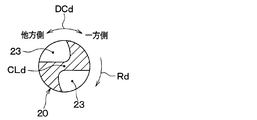
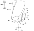
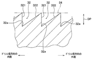
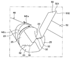
- FIG. 1 It is a figure which showed the whole structure of the drill in 1st Embodiment. It is sectional drawing which showed the outline of the II-II cross section of FIG. It is an enlarged view schematically showing the part III of FIG. 1 enlarged. It is sectional drawing which showed excerpts of a plurality of guide grooves and the periphery thereof among the IV-IV cross sections of FIG.
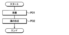
- it is a flowchart showing a manufacturing process of forming a plurality of guide grooves on a rake face of a drill, that is, a flowchart showing a method of manufacturing a drill in which a plurality of guide grooves are provided on the rake face.
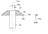
- FIG. 5 is a cross-sectional view schematically showing a schematic configuration of a rotary grindstone used in the groove forming step of FIG. 5 in the first embodiment.
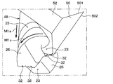
- FIG. 5 is a schematic perspective view which showed the feed direction of the workpiece to be ground in the groove forming process of FIG.
- the second embodiment it is a figure which showed the positional relationship between the workpiece and the rotary grindstone in the groove forming process of FIG. 5, and is the figure corresponding to FIG.
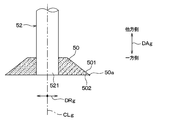
- the second embodiment it is a cross-sectional view schematically showing the schematic structure of the rotary grindstone used in the groove forming step of FIG. 5, and is the figure corresponding to FIG. 7.
- it is a schematic perspective view which showed the feed direction of the workpiece to be ground in the groove forming process of FIG. 5, and is the figure corresponding to FIG.
- it is a schematic perspective view which showed the feed direction of the workpiece to be ground in the groove forming process of FIG. 5, and is the figure corresponding to FIG.
- it is a cross-sectional view schematically showing a schematic configuration of a rotary grindstone used in the groove forming step of FIG. 5, and is a view corresponding to FIG. 7.
- the drill 10 of the present embodiment is a cutting tool that cuts a work material (specifically, drilling a hole) by being rotated around a drill axis CLd.
- the drill 10 has a rod shape extending in the axial direction DAd of the drill axis CLd, and has a drill body 20 and a shank 21.
- the drill body 20 is connected in series with the shank 21 and is provided on one side of the axial DAd of the drill axis CLd.
- the axial DAd of the drill axis CLd is also referred to as the drill axial DAd
- the radial DRd of the drill axial CLd is also referred to as the drill radial DRd.
- the circumferential direction DCd centered on the drill axis CLd shown in FIG. 2, that is, the circumferential direction DCd of the drill axis CLd is also referred to as a drill circumferential DCd.
- the axial direction DAd of the drill axis CLd is also the axial direction of the drill 10
- the radial DRd of the drill axis CLd is also the radial direction of the drill 10
- the circumferential direction DCd of the drill axis CLd is also the circumferential direction of the drill 10.
- the arrows Rd in FIGS. 1 and 2 indicate the rotation direction Rd of the drill 10 when drilling a hole in the work material, and the angle ⁇ in FIG. 1 indicates the twist angle of the chip discharge groove 23. Further, in FIG. 1, a part of the drill body 20 in the drill axial direction DAd is omitted, and the guide groove 32 (see FIG. 3) is also omitted for easy viewing.
- the shank 21 has a shape extended in the drill axial direction DAd.
- the shank 21 is fixed to a holder included in the drilling apparatus that rotates the drill 10. Then, the rotational force of the motor of the drilling apparatus is transmitted from the holder to the shank 21, whereby, as shown in FIGS. 1 and 2, the drill 10 is centered on the drill axis CLd in the direction indicated by the arrow Rd. Rotate to. That is, the drill 10 rotates to one side of the drill circumferential direction DCd shown in FIG. 2 during the cutting process for cutting the work material. In other words, during cutting, the drill 10 rotates clockwise from the rear end side of the drill body 20 toward the tip 201 side along the drill axial direction DAd.
- the drill body 20 cuts the work material and sends out the chips generated when the work material is cut from the cutting hole being machined.
- the drill body 20 has a shape extended in the drill axial direction DAd, and has a tip 201 of the drill body 20 on one side of the drill axial direction DAd.
- the drill body 20 is formed with a cutting edge 22 provided at the tip 201 of the drill body 20 and a chip discharge groove 23 spirally extending from the tip 201 of the drill body 20 to the rear end side of the drill body 20. ing.
- the rake face 24 is formed on the drill body 20.
- the rake face 24 faces the chip discharge groove 23 on the tip 201 side of the drill body 20, and extends from the cutting edge 22 along the chip discharge groove 23.
- the cutting edge 22 is provided so as to form a pair with the drill axis CLd as the center, and similarly, the chip discharge groove 23 and the rake face 24 also form a pair with the drill axis CLd as the center. It is provided in.
- the chip discharge groove 23 is recessed in the outer peripheral surface of the drill body 20, the chip discharge groove 23 is a groove opened toward the outside of the drill radial direction DRd. Is formed as.
- the chip discharge groove 23 plays a role of discharging chips generated by the cutting edge 22 during cutting from the cutting hole to the outside.
- the chip discharge groove 23 is spiral as described above. More specifically, the spiral shape of the chip discharge groove 23 is a spiral shape that rotates to one side of the DCd in the circumferential direction of the drill from the rear end side of the drill body 20 toward the tip 201 side. Further, the chip discharge groove 23 has a spiral shape extending from the rear end side of the drill body 20 toward the tip 201 side while bending clockwise. Therefore, the drill 10 of the present embodiment is a right-handed twist drill.
- a flank 25 is also formed on the tip 201 of the drill body 20, and the flank 25 plays a role of reducing the contact area between the tip 201 of the drill body 20 and the work material during cutting and suppressing cutting resistance. Fulfill.
- the cutting edge 22 is formed on the ridgeline portion between the flank surface 25 and the rake face 24.
- a plurality of guide grooves 32 provided as grinding grooves formed by grinding are formed on the rake face 24 of the drill body 20. Since there is a pair of rake faces 24 as described above, a plurality of guide grooves 32 are formed in each of the pair of rake faces 24.
- This guide groove 32 is a groove that guides chips during cutting. Specifically, the guide groove 32 suppresses curling of chips generated during cutting and regulates the outflow direction of the chips, thereby facilitating the discharge of chips.
- Each of the plurality of guide grooves 32 extends from the cutting edge 22 toward the rear end side of the drill body 20 in the direction in which the chip discharge groove 23 extends (that is, the discharge groove extension direction).
- each of the plurality of guide grooves 32 extends from the cutting edge 22 toward the rear end side of the drill body 20 in a direction along the spiral shape of the chip discharge groove 23.
- each of the plurality of guide grooves 32 extends along the discharge groove extending direction.
- the fact that the guide groove 32 is along the discharge groove extension direction means that the guide groove 32 extends in a direction that coincides with or substantially coincides with the discharge groove extension direction.
- the plurality of guide grooves 32 extend in parallel with each other. Further, the mutual intervals of the plurality of guide grooves 32 may or may not be equal intervals.
- the drill body 20 has an inner groove wall surface 321 and an outer groove wall surface 322 forming a guide groove 32 in a portion where the rake face 24 is provided.
- the inner groove wall surface 321 and the outer groove wall surface 322 are groove wall surfaces provided for each guide groove 32, and are provided for each guide groove 32.
- the inner groove wall surface 321 faces the guide groove 32 from the inside of the DRd in the radial direction of the drill.
- the outer groove wall surface 322 faces the guide groove 32 from the outside of the DRd in the radial direction of the drill.
- the guide groove 32 has a V-shaped cross section in which the groove width of the guide groove 32 becomes narrower as it is closer to the bottom 32a of the guide groove 32 in the depth direction DP of the guide groove 32. That is, the inner groove wall surface 321 and the outer groove wall surface 322 are provided so as to be closer to each other as they are closer to the bottom 32a of the guide groove 32 in the depth direction DP of the guide groove 32.
- the outer groove wall surface 322 is an inclined surface inclined with respect to the rake surface 24, and the inner groove wall surface 321 is a vertical surface perpendicular to the rake surface 24. Therefore, the inner groove wall surface 321 is oriented closer to perpendicular to the rake surface 24 than the outer groove wall surface 322.
- FIG. 5 shows a manufacturing process in which a plurality of guide grooves 32 are formed on the rake face 24 of the drill 10.
- FIG. 5 shows a method of manufacturing a drill 10 provided with a plurality of guide grooves 32.
- the workpiece 48 to be the drill 10 provided with the plurality of guide grooves 32 described above is prepared.
- the workpiece 48 is a drill 10 having the guide groove 32 when the guide groove 32 is formed. Therefore, the cutting edge 22, the chip discharge groove 23, the rake surface 24, and the flank surface 25 are already formed on the workpiece 48.
- the workpiece 48 has all the configurations of the drill 10 except for the guide groove 32.
- the process proceeds to the groove forming step P02.
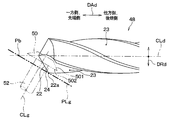
- FIG. 6 is a direction view from the top of the rake face 24 to be ground to the rake face 24 along the normal direction of the plane parallel to both the drill axis CLd and the grindstone axis CLg. It is shown as 48 and the rotary grindstone 50. Therefore, FIG. 6 shows, when the respective axis CLd and CLg are projected on a virtual plane parallel to both the drill axis CLd and the grindstone axis CLg, those axes generated on the virtual plane. It represents the intersection angle of CLd and CLg.
- a groove is formed in which a plurality of guide grooves 32 are formed on the rake face 24 by grinding the rake face 24 with the rotary grindstone 50 that rotates around the grindstone axis CLg.
- a plurality of guide grooves 32 are additionally machined on the rake face 24.
- the rotary grindstone 50 used in the groove forming step P02 rotates integrally with the grindstone rotary shaft 52 which is rotated around the grindstone axis CLg by a drive motor (not shown).
- the grindstone rotation shaft 52 extends along the axial direction DAg of the grindstone axis CLg, and has a tip portion 521 on one side of the axial direction DAg.
- the rotary grindstone 50 is fixed to the tip portion 521 of the grindstone rotary shaft 52.
- the rotary grindstone 50 is arranged so that the grindstone axis CLg intersects the longitudinal direction of the guide groove 32 (see FIG. 3).
- a virtual plane PLg that passes through the position 22a of the outer peripheral end of the cutting edge 22 connected to the rake face 24 ground in the groove forming step P02 and is orthogonal to the grindstone axis CLg and its The intersection Pb between the virtual plane PLg and the drill axis CLd is assumed. Then, in the groove forming step P02, the grindstone axis CLg with respect to the drill axis CLd so that the cutting edge 22 connected to the ground rake surface 24 is located on the rear end side of the drill body 20 with respect to the intersection Pb.
- the rotary grindstone 50 is arranged so as to be tilted.
- the virtual plane PLg is tilted so as to form an acute angle of inclination with respect to the drill axis CLd.
- the rotary grindstone 50 is held in the posture as described above with respect to the workpiece 48, and the workpiece 48 is displaced to guide the plurality of guides.
- the groove 32 is formed. That is, the grinding device (not shown) that grinds the drill 10 rotates and moves the workpiece 48 while fixing the position of the rotating rotary grindstone 50.
- the workpiece 48 is rotated to one side of the drill circumferential direction DCd (see FIG. 2) as shown by the arrow M1c, relative to the position of the rotating rotary grindstone 50, while being rotated by the arrow M1a. It is moved to one side of the drill axial direction DAd as described above.
- the workpiece 48 is fed in both the drill circumferential direction DCd and the drill axial direction DAd according to the twist of the chip discharge groove 23, whereby the rotary grindstone 50 relative to the workpiece 48 is subjected to its chips. It is moved along the discharge groove 23.
- the guide groove 32 is formed from the front end 201 side to the rear end side of the drill body 20.
- the rotary grindstone 50 used in the groove forming step P02 is obtained by rotating a sharp shape toward the outside of the radial DRg of the grindstone axis CLg around the grindstone axis CLg. It has a rotating body shape.
- the sharp shape may or may not have a corner R at the tip thereof, and the sharp shape is the same regardless of which corner R is provided. That is, the sharp shape may be sharp in consideration of the practical use of the rotary grindstone 50.
- the rotary grindstone 50 has a first grindstone surface 501 and a second grindstone surface 502.
- the first grindstone surface 501 is provided on one side of the grindstone axial center CLg in the axial direction DAg with respect to the second grindstone surface 502.
- the first grindstone surface 501 of the rotary grindstone 50 forms one of the two side surfaces sandwiching the apex 50a having the above-mentioned sharp shape, which is the basis of the shape of the rotating body of the rotary grindstone 50, and forms an annular shape around the grindstone axis CLg. It is an extending tapered surface.
- the second grindstone surface 502 is a surface that forms the other of the two side surfaces sandwiching the apex 50a having a sharp shape and extends in an annular shape around the grindstone axis CLg, and is perpendicular to the grindstone axis CLg. Vertical plane. Therefore, the second grindstone surface 502 is oriented closer to perpendicular to the grindstone axis CLg than the first grindstone surface 501.
- the inner groove wall surface 321 of the guide groove 32 is formed by the first grindstone surface 501, and the outer groove wall surface 322 of the guide groove 32 is formed by the second grindstone surface. Formed by 502.
- the guide groove 32 is formed so that the inner groove wall surface 321 and the outer groove wall surface 322 are closer to each other as they are closer to the bottom 32a of the guide groove 32 in the depth direction DP of the guide groove 32.
- the guide groove 32 is formed so that the inner groove wall surface 321 is oriented closer to perpendicular to the rake surface 24 than the outer groove wall surface 322.
- the drill of the comparative example is the same as the drill 10 of the present embodiment except that the guide groove 32 is not provided.
- the upward curl is a curl around an axis parallel to the cutting edge 22 shown in FIG. 1, and is generated by friction between the chips and the rake face 24.
- the lateral curl is a curl around the normal of the rake face 24, and is generated by the difference in speed between the inner and outer diameters of the cutting edge 22.
- the diameter of the lateral curl substantially matches the diameter of the drill, and a large lateral curl occurs.
- the chips When an upward curl and a lateral curl are generated in the chips, the chips are three-dimensionally curled from the cutting edge 22 and generated, so that the chips collide with the inner wall of the chip discharge groove 23 and are separated. In particular, when the hole to be machined is deep and the chip discharge groove 23 is narrow, chips may be clogged in the chip discharge groove 23.
- a plurality of guide grooves 32 are formed on the rake face 24 of the drill body 20.
- the cutting edge 22 cuts the work material
- the plastically deformed portion of the chip that comes into contact with the rake face 24 is fitted into the guide groove 32, and the chip is fitted into the guide groove 32 and guided. It is guided to flow out along the groove 32.
- the lateral curl is suppressed by fitting the plastically deformed portion of the chip into the guide groove 32.
- the upward curl is suppressed because the chips to which the shape of the guide groove 32 is transferred do not have a flat structure with respect to the direction in which the upward curl occurs and are difficult to bend.
- two-dimensional chips that is, linear chips having a width larger than that of the guide groove 32, are discharged in the direction along the guide groove 32. Then, such linear chips will continuously flow out along the chip discharge groove 23, and will not cause clogging in the chip discharge groove 23.
- the plurality of guide grooves 32 are provided on the rake face 24, it is possible to realize hole processing that does not cause clogging of chips. Further, by advancing the chips in the chip discharge groove 23 without being divided, the drill feed rate, which directly affects the machining efficiency, can be increased as long as the drill strength allows. Further, since the straight chips with suppressed curl are two-dimensional and not bulky, the cross-sectional area of the chip discharge groove 23 can be reduced, and the drill strength can be increased.
- a plurality of guide grooves 32 are formed by grinding the rake face 24 with the rotary grindstone 50 rotating around the grindstone axis CLg. Grooves are formed on the rake face 24.
- the plurality of guide grooves 32 of the rake face 24 are formed by grinding. Therefore, as compared with the case where the guide groove 32 is formed by laser processing, for example, it is possible to suppress a decrease in the strength of the drill 10 due to the processing of the guide groove 32.
- the rotary grindstone 50 used in the groove forming step P02 has a rotating body shape obtained by rotating a sharp shape toward the outside of the radial DRg of the grindstone axis CLg around the grindstone axis CLg. .. Therefore, the outer peripheral edge portion of the rotary grindstone 50 corresponding to the sharp tip portion can be inserted into the chip discharge groove 23, and the rake face 24 can be scraped at the outer peripheral edge portion. Therefore, for example, as compared with the case where a cylindrical rotary grindstone instead of the above-mentioned rotating body shape is used for grinding, when the guide groove 32 is formed on the rake face 24, the rotary grindstone 50 as a machining tool and the work to be processed It is easy to avoid physical interference with the object 48.
- the chip discharge groove 23 spirally extends from the tip 201 of the drill body 20 to the rear end side of the drill body 20. ..
- the spiral shape of the chip discharge groove 23 is a spiral shape that rotates to one side of the drill peripheral direction DCd (see FIG. 2) from the rear end side of the drill body 20 toward the tip 201 side.
- the workpiece 48 is rotated to one side of the drill circumferential direction DCd as shown by the arrow M1c relative to the position of the rotating rotary grindstone 50, while the arrow M1a It is moved to one side of the drill axial direction DAd as in.
- the guide groove 32 can be formed so that the guide groove 32 extends in the direction in which the chip discharge groove 23 extends.
- the inner groove wall surface 321 and the outer groove are closer to the bottom 32a of the guide groove 32 in the depth direction DP of the guide groove 32.
- the guide groove 32 is formed so that the wall surface 322 and the wall surface 322 are close to each other. Further, the guide groove 32 is formed so that the inner groove wall surface 321 is oriented closer to perpendicular to the rake surface 24 than the outer groove wall surface 322.
- the guide groove 32 has a V-shaped cross section in which the inner groove wall surface 321 is inclined to the same degree as the outer groove wall surface 322 with respect to the rake face 24, lateral curl of chips is effectively suppressed. It is possible to obtain a guide groove 32 that can effectively regulate the outflow direction of chips.
- the first grindstone surface 501 of the rotary grindstone 50 sandwiches the apex 50a having the sharp shape which is the basis of the shape of the rotating body of the rotary grindstone 50. It is a tapered surface that forms one of the two sides and extends in an annular shape around the grindstone axis CLg.
- the second grindstone surface 502 is a surface that forms the other of the two side surfaces sandwiching the apex 50a having a sharp shape and extends in an annular shape around the grindstone axis CLg. Further, the second grindstone surface 502 is oriented closer to perpendicular to the grindstone axis CLg than the first grindstone surface 501.
- the inner groove wall surface 321 of the guide groove 32 is formed by the first grindstone surface 501, and at the same time, the outer groove wall surface 322 of the guide groove 32 is the second. It is formed by the grindstone surface 502.
- the grindstone axis CLg is tilted with respect to the rake face 24 so that the rotary grindstone 50 avoids interference with the portion of the workpiece 48 that constitutes the circumference of the chip discharge groove 23. Therefore, it is possible to obtain the guide groove 32 having a useful effect such as effectively suppressing the lateral curl of the chips described above, and to avoid physical interference between the rotary grindstone 50 and the workpiece 48. It will be easier.
- the cutting edge 22 connected to the rake face 24 ground in the groove forming step P02 passes through the position 22a of the outer peripheral end and is orthogonal to the grindstone axis CLg.
- the virtual plane PLg to be used, and the intersection Pb of the virtual plane PLg and the drill axis CLd are assumed.
- the grindstone axis CLg with respect to the drill axis CLd so that the cutting edge 22 connected to the ground rake surface 24 is located on the rear end side of the drill body 20 with respect to the intersection Pb.
- the rotary grindstone 50 is arranged so as to be tilted.
- the physical arrangement of the rotary grindstone 50 that forms the guide groove 32 so that the chip discharge groove 23 extends in the extending direction is compared with the case where the rotary grindstone 50 is not arranged, for example, and the rotary grindstone 50 is physically different from the workpiece 48. It becomes easier to realize a posture that avoids physical interference.
- the grindstone rotation shaft 52 has a tip portion 521 on one side of the grindstone axis CLg in the axial direction DAg, as in the first embodiment.
- the mounting direction of the rotary grindstone 50 with respect to the grindstone rotary shaft 52 is opposite to that of the first embodiment.
- the first grindstone surface 501 is provided on the other side of the grindstone axis CLg on the opposite side of the axial direction DAg with respect to the second grindstone surface 502. Therefore, when the rotary grindstone 50 grinds the workpiece 48 in the groove forming step P02 of FIG. 5, as shown in FIG. 9, the workpiece 48 is used as a reference as compared with the first embodiment.
- the position of the grindstone rotating shaft 52 is on the opposite side of the rotating grindstone 50.
- the feed direction of the workpiece 48 indicated by the arrows M1a and M1c is the same as that of the first embodiment in this embodiment.
- this embodiment is the same as the first embodiment. Then, in the present embodiment, the effect produced from the configuration common to the above-mentioned first embodiment can be obtained in the same manner as in the first embodiment.
- the feed direction of the workpiece 48 to be ground in the groove forming step P02 in FIG. 5 is opposite to that in the first embodiment.
- the workpiece 48 is rotated to the other side of the drill circumferential direction DCd (see FIG. 2) as shown by the arrow M2c, relative to the position of the rotating rotary grindstone 50, while being rotated by the arrow M2a. It is moved to the other side of the drill axial DAd so as to.
- the guide groove 32 is formed from the rear end side of the drill body 20 to the tip 201 side. Even in this way, the guide groove 32 can be formed so that the guide groove 32 extends in the direction in which the chip discharge groove 23 (see FIG. 3) extends, as in the first embodiment.
- this embodiment is the same as the first embodiment. Then, in the present embodiment, the effect produced from the configuration common to the above-mentioned first embodiment can be obtained in the same manner as in the first embodiment.
- this embodiment is a modification based on the first embodiment, the feed direction of the workpiece 48 in this embodiment may be applied to the second embodiment.
- the drill 10 is a right-handed twist drill, but a left-handed twist drill may be used.
- the chip discharge groove 23 forms a spiral shape that extends from the rear end side of the drill body 20 toward the tip 201 side while bending counterclockwise.
- the drill 10 is a left-handed twist drill
- the positional relationship between the workpiece 48 and the rotary grindstone 50 when the rake face 24 is ground in the groove forming step P02 of FIG. 5 is different from that of FIG. It is symmetrically inverted with respect to the center CLd. Therefore, regarding the attitude of the rotary grindstone 50 with respect to the workpiece 48, the rake face 24 from above the rake face 24 to be ground along the normal direction of the plane parallel to both the drill axis CLd and the grindstone axis CLg. In the direction toward the direction, it becomes as follows. That is, in that directional view, the virtual plane PLg (see FIG. 6) is tilted counterclockwise with respect to the drill axis CLd so as to form an acute angle of inclination.
- each of the plurality of guide grooves 32 extends from the cutting edge 22 toward the rear end side of the drill body 20, and is therefore connected to the cutting edge 22.
- the plurality of guide grooves 32 may be stopped in front of the cutting edge 22 and not connected to the cutting edge 22 on the rake face 24, and may be provided at a slight distance from the cutting edge 22. Absent.
- each of the plurality of guide grooves 32 extends along the discharge groove extending direction, which is an example. Even if each of the plurality of guide grooves 32 is slightly tilted to the extent that it cannot be said to be along the discharge groove extension direction, it is sufficient that the guide grooves 32 extend in the discharge groove extension direction.
- the plurality of guide grooves 32 may be inclined at an angle of about 20 degrees with respect to the extension direction of the discharge groove.
- the plurality of guide grooves 32 extend parallel to each other, but they may not be parallel to each other.
- a plurality of guide grooves 32 are formed on the rake face 24, but one guide groove 32 may be used.
- the inner groove wall surface 321 is a vertical surface perpendicular to the rake surface 24, but is inclined with respect to the rake surface 24. Can also be considered.
- both the inner groove wall surface 321 and the outer groove wall surface 322 have a linear cross-sectional shape, but have a curved cross-sectional shape. It doesn't matter if there is one.
- the second grindstone surface 502 of the rotary grindstone 50 is a vertical surface perpendicular to the grindstone axis CLg, but the guide groove formed by the rotary grindstone 50. It does not matter if the surface is tapered according to the cross-sectional shape of 32. For example, as shown in FIG. 13, it is conceivable that both the first grindstone surface 501 and the second grindstone surface 502 of the rotary grindstone 50 are tapered surfaces.
- the chip discharge groove is formed by grinding the rake face with a rotating grindstone that rotates around the grindstone axis.
- Groove formation is performed to form a grinding groove extending in the stretching direction on the rake face.
- a rotating body shape obtained by crossing the grindstone axis with respect to the longitudinal direction of the grinding groove and rotating a sharp shape toward the outside in the radial direction of the grindstone axis around the grindstone axis. Is used as a rotary grindstone.
- the spiral shape of the chip discharge groove is a spiral that rotates in one side in the circumferential direction about the center of the drill axis from the rear end side to the tip side of the drill body. It is a shape. Further, in the groove formation, the workpiece is moved to one side in the axial direction of the drill axis while rotating one side in the circumferential direction relative to the position of the rotary grindstone. As a result, the grinding groove can be formed so that the grinding groove extends in the direction in which the chip discharging groove extends.
- the workpiece is rotated to the other side opposite to one side in the circumferential direction relative to the position of the rotary grindstone in the axial direction. Move to the other side opposite to one side. Even in this way, the grinding groove can be formed so that the grinding groove extends in the direction in which the chip discharging groove extends.
- the grinding groove is formed from the inner groove wall surface facing the grinding groove from the inside in the radial direction of the drill axis and the grinding groove from the outside in the radial direction of the drill axis. It is formed by a facing outer groove wall surface.
- the inner groove wall surface and the outer groove wall surface are closer to each other as they are closer to the bottom of the grinding groove in the depth direction of the grinding groove, and the inner groove wall surface is scooped more than the outer groove wall surface.
- the grinding groove is formed so as to be oriented in a direction close to perpendicular to the surface.
- the grinding groove has a V-shaped cross section having a symmetrical shape in which the inner groove wall surface is inclined to the same degree as the outer groove wall surface with respect to the rake face, lateral curl of chips is effectively suppressed. It is possible to obtain a grinding groove that can effectively regulate the outflow direction of chips.
- the rotary grindstone is a first grindstone surface which is a tapered surface which forms one of the two side surfaces sandwiching the apex of the sharp shape and extends in an annular shape around the grindstone axis. It has a second grindstone surface that forms the other of the above two side surfaces and extends in an annular shape around the grindstone axis. The second grindstone surface is oriented closer to perpendicular to the grindstone axis than the first grindstone surface. Then, in the groove formation, the inner groove wall surface is formed by the first grindstone surface, and the outer groove wall surface is formed by the second grindstone surface.
- the axis of the grindstone is tilted with respect to the rake face so that the rotary grindstone avoids interference with the portion of the workpiece that constitutes the circumference of the chip discharge groove. Therefore, it is possible to obtain a grinding groove having a useful effect such as effectively suppressing the lateral curl of the chips described above, and the physics of the rotary grindstone and the workpiece to be a drill provided with the grinding groove. It becomes easy to avoid physical interference.
- the second grindstone surface is a surface perpendicular to the grindstone axis.
- the grindstone shaft with respect to the drill axis so that the cutting edge connected to the rake face to be ground is located on the rear end side of the drill body from the predetermined intersection.
- the rotary grindstone is placed with the heart tilted.
- the predetermined intersection is the intersection of the virtual plane passing through the position of the outer peripheral end of the cutting edge connected to the ground rake surface and orthogonal to the grindstone axis and the drill axis.
Landscapes
- Engineering & Computer Science (AREA)
- Mechanical Engineering (AREA)
- Drilling Tools (AREA)
- Grinding And Polishing Of Tertiary Curved Surfaces And Surfaces With Complex Shapes (AREA)
- Finish Polishing, Edge Sharpening, And Grinding By Specific Grinding Devices (AREA)
Abstract
L'invention concerne un procédé de fabrication d'un foret (10) à l'intérieur duquel sont formés un bord de coupe (22), une rainure d'évacuation de copeaux (23) s'étendant en spirale et une face de coupe (24) et qui est amené à tourner autour de la ligne centrale de foret (CLd), comprenant (P01) la préparation d'une pièce à travailler (48) qui doit devenir le foret. Un bord de coupe, une rainure d'évacuation de copeaux et une face de coupe sont formés à l'intérieur de la pièce à travailler. Le procédé de fabrication du foret comprend en outre, après la préparation de la pièce à travailler, (P02) la formation d'une rainure dans laquelle une rainure de meulage (32) s'étendant dans une direction dans laquelle la rainure d'évacuation de copeaux s'étend est formée dans la face de coupe par meulage de la face de coupe avec une meule rotative (50) tournant autour de la ligne centrale de meule (CLg). Lors de la formation de la rainure, la ligne centrale de meule est amenée à se croiser avec la direction longitudinale de la rainure de meulage. De plus, dans la formation de la rainure, un article en forme de corps rotatif, obtenu par rotation, autour de la ligne centrale de meule, d'une forme pointue vers l'extérieur dans la direction radiale (DRg) de la ligne centrale de meule, est utilisé en tant que meule rotative.
Priority Applications (3)
| Application Number | Priority Date | Filing Date | Title |
|---|---|---|---|
| CN202080021432.4A CN113646127B (zh) | 2019-03-25 | 2020-02-27 | 钻头的制造方法 |
| DE112020001436.3T DE112020001436T5 (de) | 2019-03-25 | 2020-02-27 | Verfahren zum Herstellen eines Bohrers |
| US17/481,450 US20220001464A1 (en) | 2019-03-25 | 2021-09-22 | Method of producing drill |
Applications Claiming Priority (2)
| Application Number | Priority Date | Filing Date | Title |
|---|---|---|---|
| JP2019056939A JP7263872B2 (ja) | 2019-03-25 | 2019-03-25 | ドリルの製造方法 |
| JP2019-056939 | 2019-03-25 |
Related Child Applications (1)
| Application Number | Title | Priority Date | Filing Date |
|---|---|---|---|
| US17/481,450 Continuation US20220001464A1 (en) | 2019-03-25 | 2021-09-22 | Method of producing drill |
Publications (1)
| Publication Number | Publication Date |
|---|---|
| WO2020195511A1 true WO2020195511A1 (fr) | 2020-10-01 |
Family
ID=72611865
Family Applications (1)
| Application Number | Title | Priority Date | Filing Date |
|---|---|---|---|
| PCT/JP2020/008004 Ceased WO2020195511A1 (fr) | 2019-03-25 | 2020-02-27 | Procédé de fabrication de foret |
Country Status (5)
| Country | Link |
|---|---|
| US (1) | US20220001464A1 (fr) |
| JP (1) | JP7263872B2 (fr) |
| CN (1) | CN113646127B (fr) |
| DE (1) | DE112020001436T5 (fr) |
| WO (1) | WO2020195511A1 (fr) |
Cited By (1)
| Publication number | Priority date | Publication date | Assignee | Title |
|---|---|---|---|---|
| JP2022173036A (ja) * | 2021-05-07 | 2022-11-17 | 創國興業有限公司 | ドリルの再製造方法 |
Families Citing this family (2)
| Publication number | Priority date | Publication date | Assignee | Title |
|---|---|---|---|---|
| JP2023035551A (ja) * | 2021-09-01 | 2023-03-13 | 富士精工株式会社 | ドリル |
| CN117444776B (zh) * | 2023-12-12 | 2024-07-05 | 深圳市金洲精工科技股份有限公司 | 钻头加工控制方法和装置 |
Citations (4)
| Publication number | Priority date | Publication date | Assignee | Title |
|---|---|---|---|---|
| JPS49111293A (fr) * | 1973-02-26 | 1974-10-23 | ||
| JPS63110364U (fr) * | 1987-01-06 | 1988-07-15 | ||
| JPH0691510A (ja) * | 1992-09-07 | 1994-04-05 | Furukawa Electric Co Ltd:The | 傾斜面溝を有する部品の製造方法 |
| JP2008272856A (ja) * | 2007-04-26 | 2008-11-13 | Osg Corp | スパイラルタップ |
Family Cites Families (18)
| Publication number | Priority date | Publication date | Assignee | Title |
|---|---|---|---|---|
| GB152750A (en) * | 1919-07-17 | 1920-10-18 | Hilger Ltd Adam | Improved means for illuminating a small object with intense light |
| BE424785A (fr) * | 1936-11-24 | |||
| US3098325A (en) * | 1961-05-15 | 1963-07-23 | Mcculloch Corp | Fluted-cutter sharpener |
| US3178857A (en) * | 1962-09-21 | 1965-04-20 | Grob & Tesker Corp | Drill grinding method and apparatus |
| US3610075A (en) * | 1968-07-01 | 1971-10-05 | Illinois Tool Works | Method of producing a plurality of cutting tools from a single fluted bar |
| US4605347A (en) * | 1982-12-27 | 1986-08-12 | Lockheed Missiles & Space Company, Inc. | High speed drill reamer |
| DE3730378A1 (de) * | 1987-09-10 | 1989-03-23 | Micro Crystal Ag | Schneidwerkzeug, insbesondere bohrer und/oder fraeser |
| US6419561B1 (en) * | 2000-10-05 | 2002-07-16 | Kennametal Inc. | Method and apparatus for making a cutting tool having a plurality of margins |
| US7306411B2 (en) * | 2002-09-03 | 2007-12-11 | Mitsubishi Materials Corporation | Drill with groove width variation along the drill and double margin with a thinning section at the tip |
| JP5224331B2 (ja) | 2008-02-28 | 2013-07-03 | 富山県 | 切削工具及びうねり形状の作製方法 |
| CN101780553B (zh) * | 2009-01-15 | 2012-07-18 | 株式会社钨钛合金 | 钻头及其磨削加工方法 |
| DE102013202578B4 (de) * | 2013-02-18 | 2014-08-28 | Kennametal Inc. | Verfahren zur Herstellung einer sich in Axialrichtung erstreckenden Werkzeugspitze sowie Werkzeugspitze |
| WO2014208421A1 (fr) * | 2013-06-26 | 2014-12-31 | 京セラ株式会社 | Foret |
| SG10201805079YA (en) | 2013-09-27 | 2018-07-30 | Hoya Corp | Conductive film coated substrate, multilayer reflectivefilm coated substrate, reflective mask blank, reflectivemask, and semiconductor device manufacturing method |
| EP3175943B1 (fr) * | 2014-07-29 | 2024-08-28 | KYOCERA Corporation | Foret et procédé de fabrication d'un produit de coupe l'utilisant |
| JP6652496B2 (ja) * | 2014-10-24 | 2020-02-26 | 京セラ株式会社 | ドリルおよびそれを用いた切削加工物の製造方法 |
| DE102016200404B4 (de) * | 2016-01-14 | 2018-08-16 | Kennametal Inc. | Verfahren zur Herstellung eines Rotationswerkzeugs und Rotationswerkzeug |
| WO2017179689A1 (fr) * | 2016-04-15 | 2017-10-19 | 三菱日立ツール株式会社 | Trépan à petit diamètre |
-
2019
- 2019-03-25 JP JP2019056939A patent/JP7263872B2/ja active Active
-
2020
- 2020-02-27 DE DE112020001436.3T patent/DE112020001436T5/de active Pending
- 2020-02-27 WO PCT/JP2020/008004 patent/WO2020195511A1/fr not_active Ceased
- 2020-02-27 CN CN202080021432.4A patent/CN113646127B/zh active Active
-
2021
- 2021-09-22 US US17/481,450 patent/US20220001464A1/en active Pending
Patent Citations (4)
| Publication number | Priority date | Publication date | Assignee | Title |
|---|---|---|---|---|
| JPS49111293A (fr) * | 1973-02-26 | 1974-10-23 | ||
| JPS63110364U (fr) * | 1987-01-06 | 1988-07-15 | ||
| JPH0691510A (ja) * | 1992-09-07 | 1994-04-05 | Furukawa Electric Co Ltd:The | 傾斜面溝を有する部品の製造方法 |
| JP2008272856A (ja) * | 2007-04-26 | 2008-11-13 | Osg Corp | スパイラルタップ |
Cited By (2)
| Publication number | Priority date | Publication date | Assignee | Title |
|---|---|---|---|---|
| JP2022173036A (ja) * | 2021-05-07 | 2022-11-17 | 創國興業有限公司 | ドリルの再製造方法 |
| JP7326672B2 (ja) | 2021-05-07 | 2023-08-16 | 創國興業有限公司 | ドリルの再製造方法 |
Also Published As
| Publication number | Publication date |
|---|---|
| JP7263872B2 (ja) | 2023-04-25 |
| US20220001464A1 (en) | 2022-01-06 |
| CN113646127B (zh) | 2024-02-27 |
| CN113646127A (zh) | 2021-11-12 |
| JP2020157396A (ja) | 2020-10-01 |
| DE112020001436T5 (de) | 2021-12-16 |
Similar Documents
| Publication | Publication Date | Title |
|---|---|---|
| JP2018534159A (ja) | 旋削インサートおよび方法 | |
| JP7125611B2 (ja) | エンドミル | |
| CN113646127B (zh) | 钻头的制造方法 | |
| WO2011158526A1 (fr) | Procédé de fabrication d'une fraise de forme et outil de rectification d'une fraise de forme | |
| JP2010234462A (ja) | エンドミル | |
| WO2019044791A1 (fr) | Alésoir conique | |
| WO2017199911A1 (fr) | Procédé de formation de dépressions grâce à un outil de coupe rotatif | |
| JPWO2018216764A1 (ja) | 回転工具 | |
| JP6226114B2 (ja) | ねじ切りフライス及びそれを用いた管用めねじ加工方法 | |
| JP7364921B2 (ja) | エンドミル | |
| JP4088271B2 (ja) | 切削工具 | |
| JP6941047B2 (ja) | 回転工具及び切削加工物の製造方法 | |
| JP6999031B2 (ja) | テーパエンドミル | |
| JP2007276010A (ja) | 回転切削工具及びその製造方法 | |
| EP3812070B1 (fr) | Fraise à queue à rainurer | |
| JP6902285B2 (ja) | 切削工具 | |
| JP6342662B2 (ja) | ドリルおよびそれを用いた切削加工物の製造方法 | |
| JP7138927B2 (ja) | ドリル | |
| JP2011056608A (ja) | スクエアエンドミル | |
| JP2017196694A (ja) | エンドミル | |
| JP6902284B2 (ja) | 切削工具 | |
| JP7386022B2 (ja) | リーマ | |
| JP6294095B2 (ja) | ドリルおよびそれを用いた切削加工物の製造方法 | |
| CN114096378A (zh) | 凹痕加工方法 | |
| JP7671409B2 (ja) | ボールエンドミル |
Legal Events
| Date | Code | Title | Description |
|---|---|---|---|
| 121 | Ep: the epo has been informed by wipo that ep was designated in this application |
Ref document number: 20779003 Country of ref document: EP Kind code of ref document: A1 |
|
| 122 | Ep: pct application non-entry in european phase |
Ref document number: 20779003 Country of ref document: EP Kind code of ref document: A1 |