WO2020195865A1 - Accessoire d'optométrie, dispositif de commande et système de microscope ophtalmique - Google Patents
Accessoire d'optométrie, dispositif de commande et système de microscope ophtalmique Download PDFInfo
- Publication number
- WO2020195865A1 WO2020195865A1 PCT/JP2020/010690 JP2020010690W WO2020195865A1 WO 2020195865 A1 WO2020195865 A1 WO 2020195865A1 JP 2020010690 W JP2020010690 W JP 2020010690W WO 2020195865 A1 WO2020195865 A1 WO 2020195865A1
- Authority
- WO
- WIPO (PCT)
- Prior art keywords
- optical system
- lens
- image
- information
- optometry
- Prior art date
- Legal status (The legal status is an assumption and is not a legal conclusion. Google has not performed a legal analysis and makes no representation as to the accuracy of the status listed.)
- Ceased
Links
Images




Classifications
-
- H—ELECTRICITY
- H04—ELECTRIC COMMUNICATION TECHNIQUE
- H04N—PICTORIAL COMMUNICATION, e.g. TELEVISION
- H04N13/00—Stereoscopic video systems; Multi-view video systems; Details thereof
- H04N13/20—Image signal generators
- H04N13/204—Image signal generators using stereoscopic image cameras
- H04N13/239—Image signal generators using stereoscopic image cameras using two two-dimensional [2D] image sensors having a relative position equal to or related to the interocular distance
-
- A—HUMAN NECESSITIES
- A61—MEDICAL OR VETERINARY SCIENCE; HYGIENE
- A61B—DIAGNOSIS; SURGERY; IDENTIFICATION
- A61B3/00—Apparatus for testing the eyes; Instruments for examining the eyes
- A61B3/0016—Operational features thereof
-
- A—HUMAN NECESSITIES
- A61—MEDICAL OR VETERINARY SCIENCE; HYGIENE
- A61B—DIAGNOSIS; SURGERY; IDENTIFICATION
- A61B3/00—Apparatus for testing the eyes; Instruments for examining the eyes
- A61B3/0016—Operational features thereof
- A61B3/0041—Operational features thereof characterised by display arrangements
-
- A—HUMAN NECESSITIES
- A61—MEDICAL OR VETERINARY SCIENCE; HYGIENE
- A61B—DIAGNOSIS; SURGERY; IDENTIFICATION
- A61B3/00—Apparatus for testing the eyes; Instruments for examining the eyes
- A61B3/0075—Apparatus for testing the eyes; Instruments for examining the eyes provided with adjusting devices, e.g. operated by control lever
-
- A—HUMAN NECESSITIES
- A61—MEDICAL OR VETERINARY SCIENCE; HYGIENE
- A61B—DIAGNOSIS; SURGERY; IDENTIFICATION
- A61B3/00—Apparatus for testing the eyes; Instruments for examining the eyes
- A61B3/02—Subjective types, i.e. testing apparatus requiring the active assistance of the patient
- A61B3/08—Subjective types, i.e. testing apparatus requiring the active assistance of the patient for testing binocular or stereoscopic vision, e.g. strabismus
-
- A—HUMAN NECESSITIES
- A61—MEDICAL OR VETERINARY SCIENCE; HYGIENE
- A61B—DIAGNOSIS; SURGERY; IDENTIFICATION
- A61B3/00—Apparatus for testing the eyes; Instruments for examining the eyes
- A61B3/10—Objective types, i.e. instruments for examining the eyes independent of the patients' perceptions or reactions
- A61B3/13—Ophthalmic microscopes
-
- A—HUMAN NECESSITIES
- A61—MEDICAL OR VETERINARY SCIENCE; HYGIENE
- A61B—DIAGNOSIS; SURGERY; IDENTIFICATION
- A61B3/00—Apparatus for testing the eyes; Instruments for examining the eyes
- A61B3/10—Objective types, i.e. instruments for examining the eyes independent of the patients' perceptions or reactions
- A61B3/14—Arrangements specially adapted for eye photography
-
- A—HUMAN NECESSITIES
- A61—MEDICAL OR VETERINARY SCIENCE; HYGIENE
- A61F—FILTERS IMPLANTABLE INTO BLOOD VESSELS; PROSTHESES; DEVICES PROVIDING PATENCY TO, OR PREVENTING COLLAPSING OF, TUBULAR STRUCTURES OF THE BODY, e.g. STENTS; ORTHOPAEDIC, NURSING OR CONTRACEPTIVE DEVICES; FOMENTATION; TREATMENT OR PROTECTION OF EYES OR EARS; BANDAGES, DRESSINGS OR ABSORBENT PADS; FIRST-AID KITS
- A61F9/00—Methods or devices for treatment of the eyes; Devices for putting in contact-lenses; Devices to correct squinting; Apparatus to guide the blind; Protective devices for the eyes, carried on the body or in the hand
- A61F9/007—Methods or devices for eye surgery
-
- G—PHYSICS
- G06—COMPUTING OR CALCULATING; COUNTING
- G06T—IMAGE DATA PROCESSING OR GENERATION, IN GENERAL
- G06T5/00—Image enhancement or restoration
- G06T5/80—Geometric correction
-
- H—ELECTRICITY
- H04—ELECTRIC COMMUNICATION TECHNIQUE
- H04N—PICTORIAL COMMUNICATION, e.g. TELEVISION
- H04N9/00—Details of colour television systems
- H04N9/64—Circuits for processing colour signals
- H04N9/646—Circuits for processing colour signals for image enhancement, e.g. vertical detail restoration, cross-colour elimination, contour correction, chrominance trapping filters
-
- G—PHYSICS
- G06—COMPUTING OR CALCULATING; COUNTING
- G06T—IMAGE DATA PROCESSING OR GENERATION, IN GENERAL
- G06T2207/00—Indexing scheme for image analysis or image enhancement
- G06T2207/10—Image acquisition modality
- G06T2207/10004—Still image; Photographic image
- G06T2207/10012—Stereo images
-
- G—PHYSICS
- G06—COMPUTING OR CALCULATING; COUNTING
- G06T—IMAGE DATA PROCESSING OR GENERATION, IN GENERAL
- G06T2207/00—Indexing scheme for image analysis or image enhancement
- G06T2207/10—Image acquisition modality
- G06T2207/10024—Color image
-
- G—PHYSICS
- G06—COMPUTING OR CALCULATING; COUNTING
- G06T—IMAGE DATA PROCESSING OR GENERATION, IN GENERAL
- G06T2207/00—Indexing scheme for image analysis or image enhancement
- G06T2207/10—Image acquisition modality
- G06T2207/10056—Microscopic image
-
- G—PHYSICS
- G06—COMPUTING OR CALCULATING; COUNTING
- G06T—IMAGE DATA PROCESSING OR GENERATION, IN GENERAL
- G06T2207/00—Indexing scheme for image analysis or image enhancement
- G06T2207/30—Subject of image; Context of image processing
- G06T2207/30004—Biomedical image processing
- G06T2207/30041—Eye; Retina; Ophthalmic
-
- H—ELECTRICITY
- H04—ELECTRIC COMMUNICATION TECHNIQUE
- H04N—PICTORIAL COMMUNICATION, e.g. TELEVISION
- H04N13/00—Stereoscopic video systems; Multi-view video systems; Details thereof
- H04N13/20—Image signal generators
- H04N13/296—Synchronisation thereof; Control thereof
Definitions
- This technology relates to optometry attachments, control devices and ophthalmic microscope systems used in ophthalmic surgery and the like.
- an optometry attachment with a front lens may be added to the ophthalmic surgery microscope.
- a wide-angle lens is widely used as a front lens in vitrectomy, and an angle mirror is widely used as a front lens in minimally invasive glaucoma surgery (MIGS), which treats the angle.
- MIGS minimally invasive glaucoma surgery
- an ophthalmologic operating microscope to which an attachment for wide-angle observation including a wide-angle lens, which is an attachment for optometry, is added is suitable for observing a wide range of fundus.
- the addition of this wide-angle observation attachment causes distortion in the image of the eye to be inspected obtained through the wide-angle lens.
- various optical conditions in the microscope are changed by adding the attachment for wide-angle observation.
- Patent Document 1 describes that the image inversion system of the microscope is switched on by joining the optometry attachment.
- the purpose of this technique is to provide an optometry attachment, a control device, and an ophthalmic microscope system capable of providing an image suitable for observing the eye to be examined.
- the optometry attachment includes a joint, a pre-optical system, and a communication unit.
- the joint can be joined to an ophthalmic microscope.
- the front optical system includes a front lens that can be placed in front of the eye to be inspected.
- the communication unit transmits information about the pre-optical system to an external device.
- a storage unit for storing optical characteristic information of the pre-optical system may be further provided as information regarding the pre-optical system.
- the optical characteristic information of the front optical system may include at least one of the functional characteristic information of the front lens, the shape of the front lens, and the material of the front lens.
- the functional characteristic information may include at least one of the focal length, distortion coefficient, refractive index, wavelength characteristic, and polarization characteristic of the front lens.
- a state information acquisition unit for acquiring state information of the optical system may be further provided as information regarding the pre-optical system.
- the state information of the front optical system may include the position information of the front lens.
- the front optical system has the front lens and an intermediate lens arranged between the front lens and the ophthalmic microscope, and the state information of the front optical system is the position of the intermediate lens. Information, at least one of the distance information between the intermediate lens and the front lens may be further included.
- the front lens may be configured to be replaceable, and the storage unit may be configured to be writable with optical characteristic information of the front optical system.
- a pre-optical system control unit that controls the pre-optical system based on the control signal from the external device may be further provided.
- control device includes a communication unit.
- the communication unit receives information about the anterior optical system of an optometry attachment having an anterior optical system including an anterior lens that can be placed in front of the eye to be inspected.
- An image acquisition unit that acquires an image of the eye to be inspected in which the front lens is arranged in front, and an image generation unit that performs image processing on the captured image using information about the front optical system to generate a display image. May be further provided.
- the optometry attachment may further include a storage unit that stores optical characteristic information of the pre-optical system as information regarding the pre-optical system.
- the information about the front optical system includes the distortion coefficient of the front lens.
- the image generation unit may generate the display image by correcting the distortion of the captured image using the distortion coefficient.
- the information regarding the front optical system includes the material of the front lens, and the image generation unit may generate the display image by controlling the maximum magnification based on the material of the lens.
- the information regarding the front optical system includes the polarization characteristics of the front lens, and the image generation unit performs specular reflection removal processing on the captured image based on the polarization characteristics of the front lens to display the display image. It may be generated.
- the information regarding the front optical system includes the shape of the front lens, and the image generation unit uses the shape information of the front lens to perform chromatic aberration correction processing on the captured image to generate the display image. You may.
- the captured image is a stereo image
- the information about the front optical system includes the focal length of the front lens
- the image generator uses the focal length of the front lens to obtain the disparity of the stereo image.
- the display image may be generated under control.
- the optometry attachment is configured to be connectable to an ophthalmic microscope having an observation optical system, and is controlled to control at least one of the observation optical system and the pre-optical system by using information on the pre-optical system.
- a microscope control signal generation unit that generates a signal may be further provided.
- the ophthalmologic microscope system includes an ophthalmology microscope, an optometry attachment, and a control device.
- the optometry attachment includes a junction to be joined to the ophthalmic microscope, a pre-optical system including a pre-lens that can be placed in front of the eye to be inspected, and a communication unit that transmits information about the pre-optical system.
- the control device includes a communication unit that receives information about the pre-optical system.
- the ophthalmic microscope further includes an image pickup element
- the control device includes an image acquisition unit for acquiring an image of the eye to be inspected in which the front lens taken by the image pickup element is arranged in front, and the front lens.
- An image generation unit that processes the captured image using information about the optical system to generate a display image is further provided.
- the ophthalmic microscope further includes an observation optical system, and the control device uses information about the pre-optical system to generate a control signal for controlling at least one of the observation optical system and the pre-optical system. It further includes a microscope control signal generation unit to generate.
- the ophthalmic microscope system according to the embodiment of the present technology will be described.
- an example of performing vitrectomy using an ophthalmic microscope in which a wide-angle observation attachment equipped with a front optical system including a wide-angle lens (front lens) is attached to the microscope as an attachment for optometry is given. I will explain.
- HUS Heads Up Surgery
- an ophthalmic microscope such as a doctor or an assistant to observe and perform surgery while viewing an image taken by an image sensor on a display device instead of looking through the microscope.
- An example applied to the system will be explained.
- a display image is displayed, which is a surgical field image obtained by performing image processing on the captured image taken by the image sensor provided in the microscope.
- the optometry attachment has information on the pre-optical system, and in the ophthalmic microscope system of the present embodiment, the image of the captured image is used by using the optical characteristic information of the pre-optical system, which is information on the pre-optical system. Processing is done.
- the optometry attachment has a state information acquisition unit for acquiring state information of the front optical system, and in the ophthalmic microscope system of the present embodiment, the front optical system is information about the front optical system.
- the optical system of the microscope is controlled using the state information.
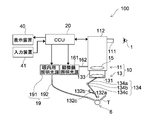
- FIG. 1 is a schematic view showing the configuration of an ophthalmic microscope system (hereinafter referred to as a microscope system) 100 according to the present embodiment.
- the microscope system 100 includes an ophthalmic microscope with an optometry attachment (hereinafter referred to as a microscope with an attachment) 10 and a camera control unit as a control device (hereinafter referred to as a CCU (Camera Control Unit)). .) 20, a display device 40, and an input device 41 are provided.
- the microscope 10 with an attachment is used by the user of the microscope system 100 to observe a magnified image of the eye 6 to be inspected in a medical examination or surgery in the field of ophthalmology.
- reference numeral 1 indicates the user's eye of the microscope 10 with an attachment.
- the user can perform a medical examination and an operation while looking at the display image displayed on the display device 40.
- the eye to be inspected 6 is the eye of a patient to be examined or operated on.
- the microscope 10 with an attachment includes an ophthalmic microscope (hereinafter referred to as a microscope) 11 and an optometry attachment 13.
- the microscope 11 includes a lens barrel main body 112 having an observation lens barrel 111, a microscope illumination light source 161 as an external illumination light source, and an intraocular illuminator 19.
- the microscope 11 can be an optical microscope having a general configuration. Two observation lens barrels 111 are provided for both the left and right eyes, but the present invention is not limited to this. Details of the microscope 10 with an attachment will be described later.
- the CCU 20 uses the information of the pre-optical system 130 of the optometry attachment 13 described later to perform image processing of the captured image acquired by the image pickup device 181 mounted on the microscope 11 to generate a display image. .. Details of CCU 20 will be described later.
- the display device 40 displays a display image that has been subjected to image processing by the CCU 20 based on the image captured by the image sensor 181.
- the display device 40 is a general display or a head-mounted display. Further, the display device 40 may be a plurality of displays, for example, a display for a doctor who operates and a display for an assistant.
- the input device 41 is an input interface to the microscope system 100.
- the user can input physical information of the patient, various information related to surgery, and the like via the input device 41. Further, for example, the user can input an instruction or the like to change various settings related to the microscope according to the situation via the input device 41.
- the type of the input device 41 is not limited, and the input device 41 may be various known input devices.
- the input device 41 for example, a mouse, a keyboard, a touch panel, a switch, a foot switch, a lever, or the like can be applied.
- the touch panel may be provided on the display surface of the display device 40.
- the input device 41 includes a microphone capable of collecting the user's voice, and various inputs may be performed by voice via the microphone.
- the input device 41 is configured to be able to input various information in a non-contact manner, so that a user belonging to a clean area can operate a device belonging to a dirty area in a non-contact manner.
- the convenience of the user is improved.
- FIG. 4 and 5 are schematic views showing a state of retinal vitreous surgery with the microscope system 100. 4 and 5 show the surgical tool T used for eye surgery.
- FIG. 4 is a schematic perspective view of the eyeball of the eye 6 to be inspected, showing a state in which the intraocular illuminator 19 and the surgical instrument T are inserted into the eye, and the front lens is not shown.
- FIG. 5 corresponds to a front view of the eye 6 to be inspected in which the wide-angle lens 132a or the magnifying lens 132b as the front lens is arranged in front, and before the intraocular illuminator 19 and the surgical tool T are inserted. Shows the state of.
- FIG. 6 is a partial cross-sectional view of the eye 6 to be inspected.
- the surgical tool T is suitable for the treatment at that time.
- the surgical tool T includes a vitreous cutter, forceps, a backflush needle, an ILM (internal limiting membrane) tweezers, a laser device for retinal photocoagulation, and the like.
- ILM internal limiting membrane
- the eye 6 to be inspected is composed of tissues such as the iris 61, the crystalline lens 65, and the cornea 66.
- the pupil 64 is located between the irises 61 on the surface of the crystalline lens 65, and the angle 62 is located on the peripheral edge of the cornea 66.
- the vitreous 68 is a jelly-like tissue that occupies most of the eyeball from the back of the crystalline lens 65 to the retina 69.
- reference numeral 671 indicates a blood vessel of the fundus 67.
- the surgical instrument is in a state where the intraocular illuminator 19 is inserted inside the eye 6 to be inspected and the inside of the eye is irradiated. T is inserted into the eye and surgery is performed.
- an intraocular illuminator 19 When performing surgery, an intraocular illuminator 19, a vitreous cutter that excises and sucks the vitreous body, and a tube (not shown) for injecting perfusate to maintain the shape of the eyeball during surgery are taken in and out.
- a tubular trocca 50 serving as a guide is arranged on the eye 6 to be inspected.
- the wide-angle lens 132a (or magnifying lens 132b) is provided corresponding to the black eye when placed in front of the eye 6 to be inspected.
- the pupil 64 is observed in a state of being considerably close to the edge of the wide-angle lens 132a (or the magnifying lens 132b) in order to observe the fundus 67.
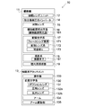
- FIG. 2 is a block diagram showing the configuration of the microscope 10 with an attachment shown in FIG. As shown in FIG. 2, the microscope 10 with an attachment includes a microscope 11 and an optometry attachment 13.
- the microscope 11 includes an eyepiece unit 12, an inverted image correction inverter 14, an objective lens 15, a microscope illumination optical system 16, an observation optical system 17, a photographing system 18, and an intraocular illuminator 19.
- the eyepiece unit 12 is further enlarged for visually observing the image created by the observation optical system 17.
- the user can observe the image transmitted through the eyepiece lens unit 12 through the observation lens barrel 111.
- the image observed by eyepiece observation is referred to as an observation image.
- the lens barrel main body 112 accommodates an inverted image correction inverter 14, an objective lens 15, a part of the microscope illumination optical system 16, an observation optical system 17, and a photographing system 18.
- the inverted image correction inverter 14 performs an inversion process of returning an inverted image inverted by a wide-angle lens 132a (or a magnifying lens 132b) to a normal image.
- the inverted image correction inverter 14 is controlled to be turned on and off, for example, based on the detection result of the connection between the microscope 11 and the optometry attachment 13.
- the microscope illumination optical system 16 illuminates the eye 6 to be inspected through the objective lens 15.
- the microscope illumination optical system 16 is divided into a microscope illumination optical system for the user's left eye and a microscope illumination optical system for the right eye. In the following description, when it is not necessary to distinguish between the right eye and the left eye, it will be referred to as a microscope illumination optical system 16.
- the microscope illumination optical system 16 is housed in a microscope illumination light source 161 and an optical fiber 162 arranged outside the lens barrel main body 112 and a lens barrel main body 112, and each of them is not shown. It has a lens, a collimating lens, and a reflection mirror.
- the microscope illumination light source 161 emits illumination light for illuminating the eye 6 from the outside of the eye 6 during a medical examination, surgery, or the like.
- One end of the optical fiber 162 is connected to the microscope illumination light source 161 and the other end is connected to the lens barrel main body 112.
- the illumination light (external illumination light) output from the microscope illumination light source 161 is guided by the optical fiber 162 and incident on the condenser lens, and becomes a parallel luminous flux by the collimating lens.
- the parallel luminous flux illumination light is reflected by the reflection mirror toward the objective lens 15 and passes through the objective lens 15 to irradiate the eye 6 to be inspected.
- the illumination light applied to the eye 6 to be inspected is reflected and scattered by the tissues of the eye 6 to be inspected such as the cornea 66 and the retina 69.
- the reflected and scattered return light passes through the objective lens 15 and is incident on the observation optical system 17.
- the return light passes through the wide-angle lens 132a (or magnifying lens 132b) described later, the reduction lens 131 as an intermediate lens, and the objective lens 15, and the observation optical system. It is incident on 17.
- the intraocular illuminator 19 is provided outside the lens barrel main body 112 and illuminates the inside of the eye 6 to be inspected.
- the intraocular illuminator 19 has an intraocular illumination light source 191 and an optical fiber 192.
- the intraocular illumination light source 191 emits illumination light (intraocular illumination light) for illuminating the inside of the eye 6 to be inspected, for example, for vitrectomy, which requires observation of the fundus over a wide range.
- One end of the optical fiber 192 can be connected to the intraocular illumination light source 191 and the other end can be inserted inside the eye 6 to be inspected.
- the illumination light output from the intraocular illumination light source 191 is guided by the optical fiber 192, and the eye to be inspected 6 is guided from the other end of the optical fiber 192. It is emitted to the inside of.
- the observation optical system 17 is for observing the eye 6 illuminated by the microscope illumination optical system 16 and the intraocular illuminator 19 through the objective lens 15.
- the observation optical system 17 transmits the projected image of the eye 6 to be inspected to the user's eye 1 or the image sensor 181 described later.
- the return light (image of the optometry) reflected and scattered by the tissue of the optometry 6 is the pre-optical system 130 of the optometry attachment 13, which will be described later.
- the image is formed on the image pickup element 181 via the objective lens 15 and the observation optical system 17, or is incident on the optometry lens unit 12. More specifically, the return light transmits the wide-angle lens 132a (or magnifying lens 132b), the reduction lens 131 as an intermediate lens, the objective lens 15, and the observation optical system 17, and forms an image on the image pickup element 181 or an eyepiece. It is incident on the lens unit 12.
- the return light (image of the optometry eye) from the optometry 6 is connected to the image pickup element 181 via the objective lens 15 and the observation optical system 17. It is incident on the image or the eyepiece lens unit 12.
- the observation optical system 17 is divided into an observation optical system for the user's left eye and an observation optical system for the right eye, each of which has an observation optical path. In particular, when it is not necessary to distinguish between the right eye and the left eye, it will be referred to as an observation optical system 17.
- the observation optical system 17 includes a focusing device 171, a variable magnification lens system 172 including a plurality of zoom lenses, an imaging lens (not shown), a variable aperture 173, and a beam splitter (not shown).
- the focusing device 171 can move the microscope 10 with an attachment up and down. As a result, the movement interval between the objective lens 15 and the patient's eye 6 to be examined can be adjusted, and the microscope 10 with the attachment is focused on the examination target area of the eye 6 to be examined. Therefore, by controlling the focusing device 171, it is possible to control the focal position of the optical system through which the return light (image of the eye to be inspected) from the eye to be inspected 6 passes until the image is formed on the image sensor 181.
- the plurality of zoom lenses of the variable magnification lens system 172 can be moved along the optical axis of the observation optical system.
- the movement of the plurality of zoom lenses changes the magnification of the captured image of the eye 6 to be inspected. Therefore, by controlling the variable magnification lens system 172, it is possible to control the magnification of the optical system through which the return light (image of the eye to be inspected) from the eye to be inspected 6 passes until the image is formed on the image sensor 181.
- the angle of view of the image, the display image, and the observation image can be controlled.
- the depth of field of the optical system that the return light from the eye 6 to be inspected (the image of the eye to be inspected) passes through until the image is formed on the image sensor 181 depends on the focal length, the aperture value, and the shooting distance of the lens. Therefore, by controlling the focusing device 171 and the variable aperture 173, the depth of field of the optical system through which the return light (image of the eye to be inspected) from the eye to be inspected 6 passes until the image is formed on the image sensor 181 is controlled. Can be done.
- the return light incident on the observation optical system 17 is magnified by the variable magnification lens system 172, passes through the imaging lens and the variable diaphragm 173, and is incident on the beam splitter.
- the beam splitter guides a part of the return light to the photographing system 18 and guides the other part of the return light to the eyepiece unit 12. Eyepiece observation can be performed by the return light incident on the eyepiece lens unit 12.
- the photographing system 18 includes an imaging lens (not shown), an image sensor 181 and the like.
- the image sensor 181 is composed of an image sensor such as a CCD (Charge Coupled Devices) or a CMOS (Complementary Metal Oxide Semiconductor), for example.
- the light receiving surface of the image sensor 181 is arranged at a position optically conjugate with the focal position of the objective lens 15.
- the photographing system 18 may correspond to both the left and right observation optical systems 17, or may correspond to either the left or right observation optical system 17.
- two image pickup elements 181 are provided, whereby a stereo image can be obtained.
- the image sensor 181 is mounted on the microscope 10 with an attachment, and the eye 6 to be inspected can be photographed via the front optical system 130 and the observation optical system 17.
- the captured image captured by the image sensor 181 is output to the CCU 20.
- the optometry attachment 13 is removably arranged in the microscope 11. As shown in FIG. 1, the optometry attachment 13 is installed between the objective lens 15 and the optometry 6.
- the optometry attachment 13 has a joint portion 133, a front optical system 130, an arm 134, a holding plate 132c, and an arm drive unit 135.
- the joint portion 133 is a portion that detachably joins the optometry attachment 13 to the microscope 11.
- the attachment of the optometry attachment 13 to the microscope 11 can be detected by energizing the contacts arranged at the portion where the optometry attachment 13 and the microscope 11 are in contact with each other. In this way, the bonding may be detected depending on whether or not the power is turned on, or a bonding state switching switch is provided so that the user can switch the bonding between the optometry attachment 13 and the microscope 11 by the switch. May be good.
- the front optical system 130 includes a reduction lens 131, a wide-angle lens 132a as a front lens, and a magnifying lens 132b.
- the wide-angle lens 132a or magnifying lens 132b
- the reduction lens 131 and the objective lens are on the observation optical path. 15.
- the observation optical system 17 is located.
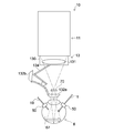
- FIG. 7 is a schematic view showing a state of eye surgery using a microscope 10 with an attachment to which an optometry attachment 13 is attached.
- FIG. 7 shows a state in which the wide-angle lens 132a is arranged in front of the eye 6 to be inspected.
- the reduction lens 131 displaces the focal plane of the observation optical path of the microscope 10 with an attachment so that it coincides with the intermediate image plane 70.
- the reduction lens 131 is not always necessary depending on the optical system of the microscope, but when a wide-angle lens is used as the front lens, the optometry attachment typically includes a reduction lens in addition to the wide-angle lens.
- the wide-angle lens 132a enables observation of the fundus 67 of the eye 6 to be inspected.
- the wide-angle lens 132a By arranging the wide-angle lens 132a in the observation optical path, it is possible to observe the fundus 67 of the eye 6 to be inspected.
- the wide-angle lens 132a produces an intermediate image in which the fundus 67 is inverted on the intermediate image plane 70.
- the magnifying lens 132b is for magnifying and observing the eye 6 to be inspected.
- the wide-angle lens 132a and the magnifying lens 132b are each held by a holding plate 132c connected to the tip of the arm 134.
- the wide-angle lens 132a and the magnifying lens 132b are fixedly arranged at both ends of the holding plate 132c having a longitudinal direction.
- the central portion of the holding plate 132c is rotatably connected to the tip of the arm 134.
- the user can select whether the lens to be arranged in front of the eye 6 to be examined is a wide-angle lens 132a or a magnifying lens 132b by rotating the holding plate 132c according to the situation.
- the switching between the wide-angle lens 132a and the magnifying lens 132b by the rotational movement of the holding plate 132c may be performed manually or may be configured to be performed automatically.
- the arm 134 supports the pre-optical system 130.
- the arm 134 has a first link 134a, a second link 134c, and a joint portion 134b, and the arm 134 is foldable.
- the first link 134a and the second link 134c are connected via the joint portion 134b, and are configured so that the positional relationship can be changed by the joint portion 134b.
- the end of the first link 134a opposite to the end where the joint 134b is located is joined to the joint 133, and the first link 134a is configured to have a variable positional relationship with respect to the joint 133.
- the end of the second link 134c opposite to the end where the joint 134b is located corresponds to the tip of the arm 134, to which the holding plate 132c is connected.
- the positional relationship between the second link 134c and the holding plate 132c is configured to be variable.
- the positions of the reduction lens 131, the wide-angle lens 132a, and the magnifying lens 132b can be changed.
- the wide-angle lens 132a (or the magnifying lens 132b) can be positioned or removed from the observation optical path.
- the positions of the reduction lens 131, the wide-angle lens 132a, and the magnifying lens 132b can be changed by moving the arm 134 and the holding plate 132c.
- the arm drive unit 135 is composed of an actuator provided on the joint unit 134b and drives the arm 134.
- the arm drive unit 135 is controlled based on the microscope control signal generated by the CCU 20.
- the microscope 11 includes a communication unit 80, an observation optical system information acquisition unit 81, and an observation optical system control unit 82 that controls the observation optical system 17.
- the communication unit 80 communicates wirelessly or by wire with an external device such as the CCU 20.
- the communication unit 80 transmits the captured image captured by the image sensor 181 to the CCU 20.
- the communication unit 80 receives the microscope control signal generated by the CCU 20.
- the observation optical system information acquisition unit 81 acquires the state information of the observation optical system 17.
- the state information of the observation optical system 17 includes focal position information that changes depending on the position of the focusing device 171 and magnification (aperture angle) information that changes depending on the position of each lens in the variable magnification lens system 172 including a plurality of zoom lenses.
- the focal position information can also be said to be the position information of the focusing device 171.
- the magnification (angle of view) information can also be said to be the position information of each lens in the variable magnification lens system 172.
- the aperture value information can also be said to be the aperture state information of the variable aperture 173.
- the observation optical system control unit 82 controls the observation optical system 17. More specifically, the observation optical system control unit 82 controls the focusing device 171, the variable magnification lens system, and the variable aperture 173 based on the microscope control signal generated by the CCU 20 based on the information about the front optical system 130. ..
- the optometry attachment 13 includes a communication unit 90, an information storage unit 91, a state information acquisition unit 92, a pre-optical system control unit 93, and a state detection unit 94.
- the communication unit 90 communicates wirelessly or by wire with an external device such as the CCU 20.
- the communication unit 90 transmits the optical characteristic information of the pre-optical system 130 stored in the information storage unit 91 to the CCU 20.
- the communication unit 90 receives the microscope control signal generated by the CCU 20. Further, when the connection between the microscope 11 and the optometry attachment 13 is detected, the communication unit 90 transmits information to the CCU 20 that the connection is in the state of connection.
- the communication unit 90 of the optometry attachment 13 and the communication unit 21 of the CCU 20 described later directly communicate with each other will be described as an example, but the present invention is not limited to this.
- the communication unit 90 of the optometry attachment 13 and the communication unit 80 of the microscope 11 can communicate with each other, and the communication unit 90 of the optometry attachment 13 and the communication unit 21 of the CCU 20 communicate with each other via the communication unit 80 of the microscope 11. It may be configured to be used.
- the information storage unit 91 stores the optical characteristic information of the pre-optical system 130 in advance.
- the optical characteristic information of the front optical system 130 includes at least one of the functional characteristic information of the front lens (wide-angle lens 132a, magnifying lens 132b), the shape of the front lens, and the material of the front lens.
- the functional characteristic information includes at least one of the focal length, distortion coefficient, refractive index, wavelength characteristic, polarization characteristic, NA (Numerical Aperture), and depth of field of each of the wide-angle lens 132a and the magnifying lens 132b as the front lens. One is included.
- the information storage unit 91 stores specific optical characteristic information of the front optical system 130, but the present invention is not limited to this.
- a different ID may be assigned to each of the different types of pre-optical systems, and the information storage unit 91 may store this ID as optical characteristic information.
- the ID of the pre-optical system and the specific optical characteristic information of the pre-optical system associated with the ID are stored in a database on a server which is an external device (not shown).
- the CCU 20 acquires an ID from the microscope 10 with an attachment via the communication unit 21, and then acquires specific optical characteristic information of the pre-optical system corresponding to the ID from the database on the server.
- the storage unit 28 of the CCU 20 described later stores the IDs assigned to the different types of pre-optical systems in advance and the specific optical characteristic information associated with the IDs. You may.
- the CCU 20 acquires stage optical characteristic information of the pre-optical system corresponding to the ID from the storage unit 28 based on the ID acquired from the microscope 10 with the attachment.
- a different ID is assigned to each type of the pre-optical system, and this ID can be used to acquire specific optical characteristic information of the pre-optical system from an external device or by a CCU. Good.
- the state information acquisition unit 92 acquires the state information of the front optical system 130.
- the state information includes the reduction lens 131, the wide-angle lens 132a, the magnifying lens 132b, and the position information of each lens.
- the position information of each lens can be detected by using, for example, an encoder (not shown).
- the state information may include distance information between lenses, orientation information of each lens by switching between the wide-angle lens 132a and the magnifying lens 132b, and the like.
- the state information is information that fluctuates due to the movement of the arm 134 and the holding plate 132c.
- the inter-lens distance information is, for example, the distance between the wide-angle lens 132a or the magnifying lens 132b and the reduction lens 131.
- the distance between lenses may be calculated using the position information of each lens.
- the lens orientation information is switching information between the wide-angle lens 132a and the magnifying lens 132b that can be arranged in front of the eye 6 to be inspected, and is information related to the orientation of the lens with respect to the eye 6 to be inspected. For example, when the wide-angle lens 132a is arranged in front of the eye 6 to be inspected, the wide-angle lens 132a is positioned in front of the eye 6 to be inspected, and the magnifying lens 132b is oriented so as not to be located in front of the eye 6 to be inspected. It becomes the direction information. In other words, the lens switching information can be said to be rotation information of the holding plate 132c.
- the front optical system control unit 93 controls the front optical system 130. More specifically, the front optical system control unit 93 controls the arm drive unit 135 based on the microscope control signal generated by the CCU 20 based on the information about the front optical system 130. As a result, the arm 134 is driven to change the positions of the reduction lens 131, the wide-angle lens 132a, and the magnifying lens 132b, and the distance between the reduction lens 131 and the wide-angle lens 132a (or the magnifying lens 132b) can be changed. ..
- the state detection unit 94 detects the presence / absence of connection between the optometry attachment 13 and the microscope 11 based on the presence / absence of energization of contacts arranged at a portion where the optometry attachment 13 and the microscope 11 are in contact with each other. Further, the state detection unit 94 detects mechanical changes in the front optical system 130, for example, the movement of the arm 134 and the movement of the holding plate 132c. The information detected by the state detection unit 94 is transmitted to the CCU 20.
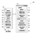
- the CCU 20 includes a communication unit 21, an image acquisition unit 22, an optical system information acquisition unit 23, a determination unit 24, a calculation unit 25, an image generation unit 26, a microscope control signal generation unit 27, and a storage unit 28.
- a communication unit 21 an image acquisition unit 22, an optical system information acquisition unit 23, a determination unit 24, a calculation unit 25, an image generation unit 26, a microscope control signal generation unit 27, and a storage unit 28.
- the communication unit 21 wirelessly or wiredly communicates with an external device such as a display device 40, a microscope 11 of a microscope 10 with an attachment, and an optometry attachment 13.
- an external device such as a display device 40, a microscope 11 of a microscope 10 with an attachment, and an optometry attachment 13.
- the communication unit 21 receives, for example, information about the pre-optical system 130 from the optometry attachment 13.
- the communication unit 21 receives the information detected by the state detection unit 94 from the optometry attachment 13.
- the information detected by the state detection unit 94 receives information that the microscope 11 and the optometry attachment 13 are in a bonded state and information on the presence or absence of mechanical changes in the pre-optical system 130.
- the communication unit 21 receives the state information of the observation optical system 17 from the microscope 11. In addition, the communication unit 21 receives the captured image from the microscope 11.
- the communication unit 21 transmits the microscope control signal generated by using the information of the front optical system 130 to the microscope 11 and the optometry attachment 13.
- the communication unit 21, the communication unit 80, and the communication unit 90 may be configured to perform wired communication, for example, via a communication cable, Wifi, Bluetooth (registered trademark), and a short-range wireless communication system (NFC (Near)). It may be configured to perform wireless communication such as Field Communication)).
- the image acquisition unit 22 acquires an image captured by the image sensor 181 from the microscope 11 via the communication unit 21.
- the optical system information acquisition unit 23 acquires information about the optical system of the microscope 10 with an attachment via the communication unit 21.
- the information regarding the optical system of the microscope 10 with attachment includes the optical characteristic information of the front optical system 130 and the optical system through which the return light (image of the eye to be inspected) from the eye to be inspected 6 passes until the image is formed on the image sensor 181. Contains information about.
- the information about the optical system that the return light passes through before forming an image on the image sensor 181 includes the state information of the pre-optical system 130 and the state information of the observation optical system 17.
- the optical characteristic information and the state information of the front optical system 130 which are information about the front optical system 130, are acquired from the optometry attachment 13.
- the optical characteristic information of the front optical system 130 is information stored in advance in the information storage unit 137 of the optometry attachment 13.
- the optical system information acquisition unit 23 acquires the optical characteristic information of the pre-optical system 130 stored in the information storage unit 137.
- the state information of the front optical system 130 is information acquired by the state information acquisition unit 92 of the optometry attachment 13.
- the optical system information acquisition unit 23 acquires the state information of the pre-optical system 130 acquired by the state information acquisition unit 92.
- the optical system information acquisition unit 23 acquires the state information of the observation optical system 17 acquired by the observation optical system information acquisition unit 81 of the microscope 11.
- the determination unit 24 determines whether or not the optometry attachment 13 and the microscope 11 are joined based on the detection result of the state detection unit 94.
- the communication unit 21 receives the detection result that the state detection unit 94 has detected the connection between the microscope 11 and the optometry attachment 13, the determination unit 24 joins the optometry attachment 13 and the microscope 11. If it is not received, it is determined that it is not joined.
- the determination unit 24 determines whether or not the state of the front optical system 130 has changed based on the detection result of the state detection unit 94.
- the determination unit 24 determines that the state change of the front optical system 130 has occurred. If it is not received, it is determined that there is no state change. In this way, the presence or absence of a change in the state of the front optical system 130 may be determined based on the change in the physical movement in the optometry attachment 13, or the captured image may be used for image recognition. The presence or absence of a state change of the front optical system 130 may be determined.
- the determination unit 24 determines whether or not the state of the front optical system 130 has changed based on the detection result of the movement of the arm 134 and the movement of the holding plate 132c by the state detection unit 94. I gave it, but it is not limited to this. For example, when there is a change in the position information detected by the encoders of the reduction lens 131, the wide-angle lens 132a, and the magnifying lens 132b, it may be determined that the state of the front optical system 130 has changed.
- the calculation unit 25 uses the information about the optical system of the microscope 10 with the attachment acquired by the optical system information acquisition unit 23 to correct the captured image, and the return light from the eye 6 of the microscope 10 with the attachment is the image sensor.
- the focal position of the optical system until the image is formed on 181 is calculated.
- a magnification suitable for the display image is calculated.
- the calculation unit 25 sets the correction parameters as follows. calculate. That is, for example, the calculation unit 25 uses the distortion coefficient of the wide-angle lens 132a as the optical characteristic information of the front optical system 130, and the distortion aberration is corrected so that the distortion of the captured image due to the arrangement of the wide-angle lens 132a is corrected. Calculate the correction parameters.
- the calculation unit 25 determines the focal position as follows. Calculate the magnification. That is, the calculation unit 25 aims so that the position of the rear focal point of the front lens (wide-angle lens 132a or the magnifying lens 132b) coincides with the position of the front focal point of the objective lens 15 and the fundus 67 is in focus.
- the focal position is calculated so as to adjust the relative positional relationship with the lens 15, the front lens (wide-angle lens 132a or the magnifying lens 132b), and the eye 6 to be inspected, and the magnification is calculated.
- the image generation unit 26 corrects the captured image based on the correction parameters calculated by the calculation unit 25, performs image processing such as color enhancement as necessary to generate a display image, and via the communication unit 21. Is output to the display device 40.
- the microscope control signal generation unit 27 generates a microscope control signal based on the calculation results of the magnification and the focal position calculated by the calculation unit 25, and outputs the microscope control signal to the microscope 10 with an attachment via the communication unit 21.
- the microscope control signal includes at least one of a control signal related to the control of the observation optical system 17 of the microscope 11 and a control signal related to the control of the pre-optical system 130 of the optometry attachment 13.
- the storage unit 28 stores the information acquired by the optical system information acquisition unit 23 in chronological order. Further, the storage unit 28 stores the distortion aberration correction parameter, the focal position, and the magnification calculated by the calculation unit 25.
- FIG. 8 is a flow chart showing the operation of the CCU 20.
- FIG. 9 is a diagram for explaining an image correction process using the optical characteristic information of the front optical system 130.
- FIG. 9A is a schematic view showing a captured image of the eye to be inspected which has not been subjected to the inversion process and the distortion correction process.
- FIG. 9B is a schematic view showing a display image which has not been subjected to inversion processing and has been subjected to distortion aberration correction processing.
- FIG. 9C is a schematic view showing a display image to which the inversion process and the distortion aberration correction process are performed.
- the communication unit 21 acquires an image captured by the image sensor 181 and a detection result detected by the state detection unit 94 from the microscope 10 with an attachment (St1).
- the captured image is output to the image acquisition unit 22.
- the detection result is output to the determination unit 24.
- the captured image G will be described with reference to FIG. 9A.
- the region inside the peripheral edge S of the wide-angle lens 132a is the inverted region R1 in which the image is inverted.
- the inversion region R1 is a region in which an image is formed by a wide-angle lens 132a as a front lens.
- a region where the image is not inverted is shown as a non-inverted region R2.
- distortion is generated by the wide-angle lens 132a, and the surgical tool T whose actual object is linear is curved.
- the determination unit 24 determines whether or not the optometry attachment 13 and the microscope 11 are joined based on the detection result received by the communication unit 21, or if the optometry attachment 13 is already joined, the pre-optical The presence or absence of a state change in the system 130 is determined (St2).
- the process proceeds to St3. On the other hand, when it is determined that the optometry attachment 13 and the microscope 11 are not joined or the state of the pre-optical system 130 does not change (NO), the process returns to St1 and the process is repeated.
- the optical system information acquisition unit 23 acquires information on the pre-optical system 130 and state information of the observation optical system 17.
- the distortion coefficient (optical characteristic information of the front optical system) of the wide-angle lens 132a (or magnifying lens 132b) as the front lens and the state of the front optical system 130 Information is acquired.
- the state information of the observation optical system 17 the magnification (angle of view) information of the observation optical system 17 is acquired.
- the information acquired by the optical system information acquisition unit 23 is stored in the storage unit 28 in chronological order.
- the calculation unit 25 uses the wide-angle lens 132a by using the distortion coefficient of the wide-angle lens 132a (or the magnifying lens 132b), the state information of the pre-optical system 130, and the magnification (image angle) information of the observation optical system 17.
- the distortion correction parameter for correcting the distortion on the captured image is calculated (St4).
- the magnification information of the observation optical system 17 is used to calculate the range to which the distortion aberration correction is applied in the captured image.
- the distortion aberration correction parameter is recalculated.
- the calculated distortion aberration correction parameter is stored in the storage unit 28.
- the image generation unit 26 may perform distortion aberration correction processing of the captured image using the distortion aberration correction parameter calculated by the calculation unit 25, or may perform correction processing such as enhancement processing.
- the display image generated by the image processing is output to the display device 40 (St5).
- the display device 40 displays the display image generated by the image generation unit 26.
- the distortion in the region of the inversion region R1 is reduced, and the shape of the surgical tool T in the image becomes linear as in the actual product. ..
- the inverted image correction inverter 14 performs an inversion process in which the inverted image of the inversion region R1 is made a normal image. Due to the inversion process by the inverted image correction inverter 14, the inverted region R1 that has become an inverted image due to the presence of the wide-angle lens becomes a normal image, while the non-inverted region that does not have a wide-angle lens and does not become an inverted image. The image is inverted in the region R2. The non-inverted region R2 whose image is inverted by the inverted image correction inverter 14 is subjected to inversion correction processing by the image generation unit 26 so as to be a normal image.
- the image generation unit 26 synthesizes the inverted region R1 that has become a normal image by the inverted processing of the inverted image correction inverter 14, and the non-inverted region R2 that has undergone the inverted correction processing, and FIG. 9C shows.
- a display image that does not give a sense of discomfort to the user is generated.
- the inversion process by the inverted image correction inverter 14 may be configured so that, for example, when the state detection unit 94 detects the connection between the optometry attachment 13 and the microscope 11, the inversion process is performed by the inverted image correction inverter 14. Good.
- the inversion processing is performed after the distortion aberration correction processing is given, but the order is not limited, and the distortion aberration correction processing may be performed after the inversion processing, or may be performed at the same time. Not done.
- the process shown in FIG. 8 is repeated.
- the distortion correction processing suitable for the state of the optical system of the microscope 10 with the attachment at that time is performed on the captured image, so that the user can use the image. , It is possible to perform surgery while always observing an appropriate display image.
- the distortion coefficient of the front lens is used as the optical characteristic information of the front optical system 130 and the captured image is subjected to distortion correction processing to generate a display image. Not limited.
- the maximum magnification of the digital zoom may be controlled by using the material information of the front lens as the optical characteristic information of the front optical system 130 to generate a display image.
- the front lens is made of, for example, plastic or glass. Since the resolution of a lens such as an MTF (Modulation Transfer Function) differs depending on the material of the front lens, the maximum magnification of the digital zoom may be controlled by the material of the front lens so that the magnification cannot exceed the resolution of the front lens. ..
- MTF Modulation Transfer Function
- the specular reflection component is obtained from the polarized image (image taken) taken by the image sensor by a known method.
- a display image may be generated by performing a specular reflection removal process for removal.
- the captured image may be subjected to chromatic aberration correction processing to generate a display image by using the shape information of the lens constituting the front optical system 130 as the optical characteristic information of the front optical system 130.
- the parallax of the stereo image may be controlled by using the focal length of the front optical system 130 as the optical characteristic information of the front optical system 130 to generate a display image.
- the distortion aberration correction processing is automatically performed using the distortion coefficient, but the user may select whether or not to perform the distortion aberration correction processing.
- a menu button for selecting whether or not to perform distortion aberration correction processing on the display surface May be displayed so that the user can select whether or not to perform distortion correction processing.
- a menu button for selecting whether or not to perform specular reflection removal processing is displayed on the display surface, and the user selects whether or not to perform specular reflection removal processing. You may be able to do it.
- the optometry attachment 13 since the optometry attachment 13 has the optical characteristic information of the pre-optical system in advance, the optical characteristic information is used to provide the user with a display image suitable for the situation. be able to.
- the microscope system 100 even if there is a change in the state of the front optical system 130, for example, a change in the positions of the front lens and the reduction lens due to the movement of the arm 134 and the holding plate 132c, information on the optical system of the microscope 10 with attachment can be obtained. Image processing is performed using this, and it is possible to always provide the user with a display image or an observation image suitable for the situation.
- the optical characteristic information of the front optical system 130 is used to pass the return light from the optical system of the microscope 10 with an attachment, more specifically, the return light from the eye 6 to be examined until the image is formed on the image pickup element 181.
- a microscope control signal for controlling the optical system is generated, and the optical system of the microscope 10 with an attachment is automatically adjusted based on the microscope control signal.
- FIG. 10 is a flow chart showing the operation of the CCU 20.
- the communication unit 21 acquires an image captured by the image sensor 181 and a detection result detected by the state detection unit 94 from the microscope 10 with an attachment (St21).
- the captured image is output to the image acquisition unit 22.
- the detection result is output to the determination unit 24.
- the determination unit 24 determines whether or not the optometry attachment 13 and the microscope 11 are joined based on the detection result received by the communication unit 21, or if the optometry attachment 13 is already joined, the pre-optical The presence or absence of a state change in the system 130 is determined (St22).
- the process proceeds to St23.
- the process returns to St21 and the process is repeated.
- the optical system information acquisition unit 23 acquires information on the pre-optical system 130 and state information of the observation optical system 17 as optical system information.
- the focal length (optical characteristic information) of the wide-angle lens 132a (or the magnifying lens 132b) as the front lens and the state information of the front optical system 130 are acquired. ..
- the state information of the front optical system 130 is the position information of each lens.
- information such as the magnification (angle of view), the focal position, and the aperture value of the observation optical system 17 is acquired.
- the information acquired by the optical system information acquisition unit 23 is stored in the storage unit 28 in chronological order.
- the calculation unit 25 uses the state information of the front optical system 130, the state information of the observation optical system 17, and the focal length of the wide-angle lens 132a (or the magnifying lens 132b) to generate the return light from the eye 6 to be inspected.
- the focal length and magnification of the optical system that passes through the image pickup element 181 before forming an image are calculated. That is, the calculation unit 25 aims so that the position of the rear focal point of the front lens (wide-angle lens 132a or the magnifying lens 132b) coincides with the position of the front focal point of the objective lens 15 and the fundus 67 is in focus.
- the focal position is calculated so as to adjust the relative positional relationship with the lens 15, the front lens (wide-angle lens 132a or the magnifying lens 132b), and the eye 6 to be inspected.
- a magnification suitable for the display image is calculated.
- the calculated focal position and magnification are stored in the storage unit 28.
- the microscope control signal generation unit 27 generates a microscope control signal for controlling each of the focusing device 171 and the variable magnification lens system 172 of the microscope 11 based on the calculated focal position and magnification, and has an attachment. It is output to the microscope 10 (St25). In this way, the process shown in FIG. 10 is repeated.
- the observation optical system control unit 82 controls the driving of the focusing device 171 and the variable magnification lens system 172 based on the microscope control signal generated by the CCU 20.
- the focal position and magnification of the optical system of the microscope 10 with the attachment to which the optometry attachment 13 is attached are automatically adjusted, and the image of the eye 6 to be observed through the front lens is observed with an appropriate display image. can do.
- the pre-optical system 130 may be controlled so that the magnification and the focal position can be adjusted.
- St25 generates and outputs a microscope control signal for driving the arm drive unit 135 of the optometry attachment 13.
- both the observation optical system 17 and the pre-optical system 130 may be controlled.
- St25 generates and outputs a microscope control signal for controlling the driving of the focusing device 171 and the variable magnification lens system 172 and a microscope control signal for driving the arm driving unit 135.
- the lens shape (for example, the curvature of the lens) is changed by electrical control such as applying pressure to the reduction lens 131 and the front lens (wide-angle lens 132a and magnifying lens 132b) constituting the front optical system 130 with an electromagnetic actuator.
- a tunable lens variable focus lens
- the optical characteristic information of the tunable lens (optical characteristic information of the front optical system), the state information of the front optical system 130 acquired from the microscope 10 with the attachment, and the state information of the observation optical system 17 are obtained. It is used to generate a microscope control signal.
- This microscope control signal is a reduction lens made of a tunable lens, a front lens, so that the position of the back focus of the front lens and the position of the front focus of the objective lens 15 coincide with each other and the fundus 67 is in focus. This is a signal for changing the lens shape of the lens.
- the optical characteristic information of the tunable lens includes the focal length range associated with each other, the distortion coefficient of the lens, the shape, and the like that the tunable lens can take.
- the observation optical system uses the NA (Numerical Aperture) of the front optical system and the depth of field information as the optical characteristic information of the front optical system 130. It may be configured to control the variable aperture 173 of 17. For example, when the depth of field of the front optical system 130 is shallow, the variable aperture 173 is controlled so that the depth of field of the observation optical system 17 is deep.
- NA Numerical Aperture
- a display device and an imaging element are not always necessary, and the present technology is applied by a user who does not use the display device. It can also be applied to an ophthalmic microscope system that performs observation and surgery by eyepiece observation with a microscope. Also in this system, the user can observe the image of the eye 6 to be observed through the front lens with an appropriate observation image.
- the optical system that the return light from the optometry 6 passes through before forming an image on the image sensor 181 is controlled. By doing so, it is possible to provide the user with a display image or an observation image of the eye 6 to be inspected suitable for a situation in which the focal position is adjusted.
- the user does not have to worry about adjusting the optical system of the microscope 10 with the attachment by joining the optometry attachment 13.
- the optometry attachment 13 having the front optical system 130 has the optical characteristic information of the front optical system 130, it assists the user in setting the microscope. can do.
- the optics of the microscope 10 with the attachment is controlled using the information about the system, and it is possible to always provide the user with a display image or an observation image suitable for the situation where the focal point is located.
- the inversion process is performed by using the inverted image correction inverter 14, but the present invention is not limited to this, and the image captured by the image sensor 181 is image-processed.
- the inversion process may be performed by the above, and will be described with reference to FIG.
- FIG. 9A is a schematic view showing an image of an eye to be inspected that has not been subjected to inversion processing and distortion correction processing.
- FIG. 9C is a schematic view showing a display image to which the inversion process and the distortion aberration correction process are performed.
- the surgical instrument T is projected in a considerably curved form through the wide-angle lens 132a.
- the distortion coefficient of the captured image G is corrected by using the distortion coefficient of the wide-angle lens 132a, which is the optical characteristic information of the front optical system, and further, the inversion processing is performed by the image processing.
- the image of the surgical instrument T becomes linear, and a display image in which the inverted region R1 is inverted is obtained.
- the inversion region R1 in the captured image G is detected by the inversion region detection unit (not shown) included in the CCU 20.
- the inversion region R1 can be detected by using object recognition. Further, the outside of the front lens (wide-angle lens 132a and magnifying lens 132b) is a region corresponding to the sclera (white eye 63), while the inside of the front lens has a color and texture like the iris and the pupil. It is also possible to detect the inverted region R1 by utilizing the fact that the appearance is a different region (black eye).
- the peripheral edge S of the front lens in the captured image since a clear edge exists on the peripheral edge S of the front lens in the captured image, it is possible to perform edge detection processing and detect the region inside the detected edge as the inversion region R1.
- the above detection method detects the inverted region R1 from one captured image.
- the image sensors 181 are mounted on the left and right sides of the microscope 10 with attachments, it is possible to obtain images captured by both the left eye and the right eye. Depth information can be extracted from the parallax information of these two captured images, and the inverted region R1 can be detected by utilizing the fact that the front lens is in front of the eye.
- the inverted region R1 it is also possible to detect the inverted region R1 by using a plurality of captured images. Specifically, the captured image when the front lens is not attached is retained, the captured image is compared with the captured image including the front lens, and the region having a large difference is detected as the inverted region R1. You may.
- the detected range of the inverted region R1 is supplied to the image generation unit 26.
- the image generation unit 26 inverts the inverted region R1 included in the captured image G output from the image sensor 181 so as to be point-symmetrical with the center of the inverted region R1 as the center point. Further, the image generation unit 26 synthesizes the inverted region R1 and the non-inverted region R2 by matching the outer circumference of the inverted inverted region R1 with the inner circumference of the non-inverted region R2.
- the image generation unit 26 can generate a display image in which the inversion is eliminated, as shown in FIG. 9C.
- the image generation unit 26 outputs the generated display image to the display device 40 and displays it on the display device 40.
- the display image may be generated by performing inversion processing by image processing, and the user can observe and treat the eye 6 to be inspected while observing the display image displayed on the display device 40. ..
- a wide-angle lens for observing the fundus of the eye has been described as an example, but an angle mirror may be used.
- the angle can be observed by using an angle mirror.
- the angle mirror is used in contact with the eye 6 to be inspected.
- intraocular illumination and reduction lens are not required.
- the optometry attachment 13 is configured to include two front lenses, a wide-angle lens 132a and a magnifying lens 132b, but may be configured to include one front lens.
- the wide-angle lens 132a and the magnifying lens 132b may be detachably configured with respect to the holding plate 132c, respectively, and the type of front lens to be used can be changed to any one. it can.
- the holding plate 132c may be configured to be detachable from the arm 134, and the front lens can be changed to an arbitrary one in the same manner.
- the information storage unit 91 of the optometry attachment 13 provides optical characteristic information of the newly mounted front lens. It may be configured so that the ID can be written. As a result, it is not necessary to change the microscope 11, and the optometry attachment can be made highly customizable and expandable.
- a joint that can be joined to an ophthalmic microscope A pre-optical system that includes a pre-lens that can be placed in front of the eye to be inspected, An optometry attachment equipped with a communication unit that transmits information about the above-mentioned pre-optical system to an external device.
- An optometry attachment further comprising a storage unit that stores optical characteristic information of the pre-optical system as information on the pre-optical system.
- the optical characteristic information of the front optical system is an optometry attachment including at least one of the functional characteristic information of the front lens, the shape of the front lens, and the material of the front lens.
- the functional characteristic information is an optometry attachment including at least one of the focal length, distortion coefficient, refractive index, wavelength characteristic, and polarization characteristic of the front lens.
- An optometry attachment further comprising a state information acquisition unit that acquires state information of the optical system as information on the pre-optical system.
- the state information of the front optical system is an attachment for optometry including the position information of the front lens.
- the optometry attachment according to (6) above has the front lens and an intermediate lens arranged between the front lens and the ophthalmologic microscope.
- the state information of the front optical system is an optometry attachment that further includes at least one of the position information of the intermediate lens and the distance information between the intermediate lens and the front lens.
- the optometry attachment according to (2) above is configured to be replaceable,
- the storage unit is an optometry attachment in which the optical characteristic information of the front optical system can be written.
- An optometry attachment further comprising a pre-optical system control unit that controls the pre-optical system based on a control signal from the external device.
- a control device including a communication unit for receiving information about the optometry, which is included in an optometry attachment having a optometry including a front lens that can be placed in front of the eye to be inspected.
- control device (11) The control device according to (10) above.
- An image acquisition unit that acquires an image of the eye to be inspected with the front lens placed in front
- a control device further comprising an image generation unit that performs image processing on the captured image using information on the pre-optical system to generate a display image.
- the control device is a control device further including a storage unit that stores optical characteristic information of the front optical system as information about the front optical system.
- the control device according to (11) or (12) above.
- the information about the front optical system includes the distortion coefficient of the front lens.
- the image generation unit is a control device that uses the distortion coefficient to correct distortion in the captured image and generate the display image.
- the control device according to (11) or (12) above.
- the information regarding the front optical system includes the material of the front lens.
- the image generation unit is a control device that controls the maximum magnification based on the material of the lens to generate the display image.
- the control device according to (11) or (12) above.
- the information about the front optical system includes the polarization characteristics of the front lens.
- the image generation unit is a control device that generates the display image by performing specular reflection removal processing on the captured image based on the polarization characteristics of the front lens.
- the control device according to (11) or (12) above.
- the information about the front optical system includes the shape of the front lens.
- the image generation unit is a control device that uses the shape information of the front lens to perform chromatic aberration correction processing on the captured image to generate the display image.
- the control device according to (11) or (12) above.
- the above captured image is a stereo image
- the information about the front optical system includes the focal length of the front lens.
- the image generation unit is a control device that uses the focal length of the front lens to control the parallax of the stereo image to generate the display image.
- the control device according to any one of (10) to (17) above.
- the optometry attachment is configured to be connectable to an ophthalmic microscope having an observation optical system.
- a control device further comprising a microscope control signal generation unit that generates a control signal for controlling at least one of the observation optical system and the pre-optical system by using the information about the pre-optical system.
- the ophthalmic microscope system according to (19) above.
- the ophthalmic microscope further includes an image sensor.
- the control device captures the captured image by using the image acquisition unit that acquires the captured image of the eye to be inspected in which the front lens is arranged in front and the information about the front optical system taken by the image sensor.
- An ophthalmic microscope system further comprising an image generator that processes and generates a display image.
- the ophthalmic microscope system according to (19) or (20) above.
- the ophthalmic microscope further includes an observation optical system.
- the control device is an ophthalmic microscope further comprising a microscope control signal generation unit that generates a control signal for controlling at least one of the observation optical system and the pre-optical system by using information about the pre-optical system. system.
Landscapes
- Health & Medical Sciences (AREA)
- Life Sciences & Earth Sciences (AREA)
- Engineering & Computer Science (AREA)
- Ophthalmology & Optometry (AREA)
- Physics & Mathematics (AREA)
- Veterinary Medicine (AREA)
- Surgery (AREA)
- Public Health (AREA)
- General Health & Medical Sciences (AREA)
- Animal Behavior & Ethology (AREA)
- Biomedical Technology (AREA)
- Heart & Thoracic Surgery (AREA)
- Medical Informatics (AREA)
- Molecular Biology (AREA)
- Biophysics (AREA)
- Signal Processing (AREA)
- Multimedia (AREA)
- Theoretical Computer Science (AREA)
- General Physics & Mathematics (AREA)
- Nuclear Medicine, Radiotherapy & Molecular Imaging (AREA)
- Vascular Medicine (AREA)
- Microscoopes, Condenser (AREA)
- Eye Examination Apparatus (AREA)
- Geometry (AREA)
Abstract
Le problème à résoudre par la présente invention est de fournir un accessoire d'optométrie, un dispositif de commande et un système de microscope ophtalmique qui peuvent donner une image appropriée pour l'observation d'un œil à examiner. La solution selon l'invention porte sur un accessoire d'optométrie qui est pourvu d'une partie de jonction, d'un système optique avant et d'une unité de communication. La partie de jonction peut être assemblée à un microscope ophtalmique. Le système optique avant comprend une lentille avant qui peut être disposée devant l'œil à examiner. L'unité de communication transmet des informations sur le système optique avant à un dispositif externe.
Priority Applications (3)
| Application Number | Priority Date | Filing Date | Title |
|---|---|---|---|
| DE112020001487.8T DE112020001487T5 (de) | 2019-03-26 | 2020-03-12 | Optischer Aufsatz, Steuervorrichtung und opthalmisches Mikroskopsystem |
| US17/593,097 US12213735B2 (en) | 2019-03-26 | 2020-03-12 | Eye examination attachment, control device, and ophthalmic microscope system |
| JP2021509017A JP7540431B2 (ja) | 2019-03-26 | 2020-03-12 | 制御装置及び眼科用顕微鏡システム |
Applications Claiming Priority (2)
| Application Number | Priority Date | Filing Date | Title |
|---|---|---|---|
| JP2019-058159 | 2019-03-26 | ||
| JP2019058159 | 2019-03-26 |
Publications (1)
| Publication Number | Publication Date |
|---|---|
| WO2020195865A1 true WO2020195865A1 (fr) | 2020-10-01 |
Family
ID=72611414
Family Applications (1)
| Application Number | Title | Priority Date | Filing Date |
|---|---|---|---|
| PCT/JP2020/010690 Ceased WO2020195865A1 (fr) | 2019-03-26 | 2020-03-12 | Accessoire d'optométrie, dispositif de commande et système de microscope ophtalmique |
Country Status (4)
| Country | Link |
|---|---|
| US (1) | US12213735B2 (fr) |
| JP (1) | JP7540431B2 (fr) |
| DE (1) | DE112020001487T5 (fr) |
| WO (1) | WO2020195865A1 (fr) |
Cited By (1)
| Publication number | Priority date | Publication date | Assignee | Title |
|---|---|---|---|---|
| JP2024527919A (ja) * | 2021-07-26 | 2024-07-26 | カール ツアイス メディテック アクチエンゲゼルシャフト | 眼の手術のための手術用顕微鏡の非接触視覚化システム |
Families Citing this family (2)
| Publication number | Priority date | Publication date | Assignee | Title |
|---|---|---|---|---|
| WO2021160195A1 (fr) * | 2020-02-13 | 2021-08-19 | Leica Camera Aktiengesellschaft | Appareil d'observation numérique |
| JP7638067B2 (ja) * | 2020-03-13 | 2025-03-03 | 株式会社トプコン | 眼科装置、その制御方法、及びプログラム |
Citations (5)
| Publication number | Priority date | Publication date | Assignee | Title |
|---|---|---|---|---|
| US5216456A (en) * | 1990-10-29 | 1993-06-01 | Volk Donald A | Optical device for use with a slit lamp biomicroscope |
| JP2017124204A (ja) * | 2017-03-06 | 2017-07-20 | 株式会社トプコン | 眼科観察装置 |
| JP2017522112A (ja) * | 2014-07-14 | 2017-08-10 | ノバルティス アーゲー | 可動広角眼科手術システム |
| US20190038135A1 (en) * | 2016-02-05 | 2019-02-07 | Samsung Electronics Co., Ltd. | Electronic device, mobile terminal and control method thereof |
| US20190076019A1 (en) * | 2017-09-08 | 2019-03-14 | Arkadiy Farberov | Ophthalmic Lens Doublet for Ophthalmoscopy |
Family Cites Families (8)
| Publication number | Priority date | Publication date | Assignee | Title |
|---|---|---|---|---|
| US6893398B2 (en) * | 2001-04-19 | 2005-05-17 | Odc Ophthalmic Development Company Ag | Device for measuring intraocular pressure, in particular a tonometer |
| JP4417035B2 (ja) | 2003-06-09 | 2010-02-17 | 株式会社トプコン | 観察装置 |
| DE102006047459A1 (de) | 2006-10-07 | 2008-04-10 | Carl Zeiss Surgical Gmbh | Ophthalmo-Operationsmikroskopsystem |
| US8210681B2 (en) * | 2007-07-17 | 2012-07-03 | Heidelberg Engineering Gmbh | Method and device for assessing the field of vision |
| GB201120771D0 (en) * | 2011-12-02 | 2012-01-11 | Ljt Projects Ltd | tear duct resistance measuring system |
| WO2016127088A1 (fr) | 2015-02-06 | 2016-08-11 | Duke University | Systèmes et procédés d'affichage stéréoscopique pour afficher des données et des informations chirurgicales dans un microscope chirurgical |
| US20190042698A1 (en) * | 2017-08-03 | 2019-02-07 | Intel Corporation | Vision deficiency adjusted graphics rendering |
| MX2021008923A (es) * | 2019-01-24 | 2022-01-04 | 6 OVER 6 VISION Ltd | Aparato, sistema y metodo para determinar uno o mas parametros de un error refractivo de un ojo examinado. |
-
2020
- 2020-03-12 WO PCT/JP2020/010690 patent/WO2020195865A1/fr not_active Ceased
- 2020-03-12 JP JP2021509017A patent/JP7540431B2/ja active Active
- 2020-03-12 DE DE112020001487.8T patent/DE112020001487T5/de active Pending
- 2020-03-12 US US17/593,097 patent/US12213735B2/en active Active
Patent Citations (5)
| Publication number | Priority date | Publication date | Assignee | Title |
|---|---|---|---|---|
| US5216456A (en) * | 1990-10-29 | 1993-06-01 | Volk Donald A | Optical device for use with a slit lamp biomicroscope |
| JP2017522112A (ja) * | 2014-07-14 | 2017-08-10 | ノバルティス アーゲー | 可動広角眼科手術システム |
| US20190038135A1 (en) * | 2016-02-05 | 2019-02-07 | Samsung Electronics Co., Ltd. | Electronic device, mobile terminal and control method thereof |
| JP2017124204A (ja) * | 2017-03-06 | 2017-07-20 | 株式会社トプコン | 眼科観察装置 |
| US20190076019A1 (en) * | 2017-09-08 | 2019-03-14 | Arkadiy Farberov | Ophthalmic Lens Doublet for Ophthalmoscopy |
Cited By (2)
| Publication number | Priority date | Publication date | Assignee | Title |
|---|---|---|---|---|
| JP2024527919A (ja) * | 2021-07-26 | 2024-07-26 | カール ツアイス メディテック アクチエンゲゼルシャフト | 眼の手術のための手術用顕微鏡の非接触視覚化システム |
| JP7534574B2 (ja) | 2021-07-26 | 2024-08-14 | カール ツアイス メディテック アクチエンゲゼルシャフト | 眼の手術のための手術用顕微鏡の非接触視覚化システム |
Also Published As
| Publication number | Publication date |
|---|---|
| US12213735B2 (en) | 2025-02-04 |
| DE112020001487T5 (de) | 2021-12-09 |
| JPWO2020195865A1 (fr) | 2020-10-01 |
| JP7540431B2 (ja) | 2024-08-27 |
| US20220175245A1 (en) | 2022-06-09 |
Similar Documents
| Publication | Publication Date | Title |
|---|---|---|
| US12329458B2 (en) | Control device, ophthalmic microscope system, ophthalmic microscope, and image processing apparatus | |
| AU2015290147B2 (en) | Movable wide-angle ophthalmic surgical system | |
| RU2675688C2 (ru) | Хирургическая система визуализации oct широкого поля обзора без использования микроскопа | |
| AU2016278755B2 (en) | Tracking system for surgical optical coherence tomography | |
| CN108652824B (zh) | 眼科手术显微镜系统 | |
| US20160235299A1 (en) | Ophthalmic surgical microscope and ophthalmic surgical attachment | |
| JP2009207590A (ja) | 実体顕微鏡 | |
| JP2018500123A (ja) | マキュラーコンタクトレンズを伴うoct手術可視化システム | |
| JP2009261438A (ja) | 眼底カメラ | |
| JP6456206B2 (ja) | 眼科装置、眼科装置の制御方法およびプログラム | |
| JP5101370B2 (ja) | 眼底撮影装置 | |
| JP7540431B2 (ja) | 制御装置及び眼科用顕微鏡システム | |
| JP2009297073A (ja) | 手術用顕微鏡 | |
| JP6912230B2 (ja) | 眼科装置 | |
| JP6638050B2 (ja) | 眼科手術用顕微鏡および眼科手術用アタッチメント | |
| JP6961066B2 (ja) | 眼科装置 | |
| JP2018166631A (ja) | 眼科撮影装置 | |
| JP2012223643A (ja) | 眼科撮像装置およびその方法 |
Legal Events
| Date | Code | Title | Description |
|---|---|---|---|
| 121 | Ep: the epo has been informed by wipo that ep was designated in this application |
Ref document number: 20779930 Country of ref document: EP Kind code of ref document: A1 |
|
| ENP | Entry into the national phase |
Ref document number: 2021509017 Country of ref document: JP Kind code of ref document: A |
|
| 122 | Ep: pct application non-entry in european phase |
Ref document number: 20779930 Country of ref document: EP Kind code of ref document: A1 |