WO2020195877A1 - Système médical, dispositif de traitement du signal et procédé de traitement du signal - Google Patents
Système médical, dispositif de traitement du signal et procédé de traitement du signal Download PDFInfo
- Publication number
- WO2020195877A1 WO2020195877A1 PCT/JP2020/010741 JP2020010741W WO2020195877A1 WO 2020195877 A1 WO2020195877 A1 WO 2020195877A1 JP 2020010741 W JP2020010741 W JP 2020010741W WO 2020195877 A1 WO2020195877 A1 WO 2020195877A1
- Authority
- WO
- WIPO (PCT)
- Prior art keywords
- algorithm
- surgical field
- information
- medical system
- interest
- Prior art date
- Legal status (The legal status is an assumption and is not a legal conclusion. Google has not performed a legal analysis and makes no representation as to the accuracy of the status listed.)
- Ceased
Links
Images


Classifications
-
- G—PHYSICS
- G16—INFORMATION AND COMMUNICATION TECHNOLOGY [ICT] SPECIALLY ADAPTED FOR SPECIFIC APPLICATION FIELDS
- G16H—HEALTHCARE INFORMATICS, i.e. INFORMATION AND COMMUNICATION TECHNOLOGY [ICT] SPECIALLY ADAPTED FOR THE HANDLING OR PROCESSING OF MEDICAL OR HEALTHCARE DATA
- G16H30/00—ICT specially adapted for the handling or processing of medical images
- G16H30/40—ICT specially adapted for the handling or processing of medical images for processing medical images, e.g. editing
-
- A—HUMAN NECESSITIES
- A61—MEDICAL OR VETERINARY SCIENCE; HYGIENE
- A61B—DIAGNOSIS; SURGERY; IDENTIFICATION
- A61B1/00—Instruments for performing medical examinations of the interior of cavities or tubes of the body by visual or photographical inspection, e.g. endoscopes; Illuminating arrangements therefor
- A61B1/04—Instruments for performing medical examinations of the interior of cavities or tubes of the body by visual or photographical inspection, e.g. endoscopes; Illuminating arrangements therefor combined with photographic or television appliances
- A61B1/045—Control thereof
-
- G—PHYSICS
- G06—COMPUTING OR CALCULATING; COUNTING
- G06T—IMAGE DATA PROCESSING OR GENERATION, IN GENERAL
- G06T1/00—General purpose image data processing
-
- G—PHYSICS
- G06—COMPUTING OR CALCULATING; COUNTING
- G06T—IMAGE DATA PROCESSING OR GENERATION, IN GENERAL
- G06T7/00—Image analysis
- G06T7/0002—Inspection of images, e.g. flaw detection
- G06T7/0012—Biomedical image inspection
-
- G—PHYSICS
- G06—COMPUTING OR CALCULATING; COUNTING
- G06T—IMAGE DATA PROCESSING OR GENERATION, IN GENERAL
- G06T7/00—Image analysis
- G06T7/50—Depth or shape recovery
- G06T7/55—Depth or shape recovery from multiple images
- G06T7/579—Depth or shape recovery from multiple images from motion
-
- G—PHYSICS
- G06—COMPUTING OR CALCULATING; COUNTING
- G06T—IMAGE DATA PROCESSING OR GENERATION, IN GENERAL
- G06T7/00—Image analysis
- G06T7/50—Depth or shape recovery
- G06T7/55—Depth or shape recovery from multiple images
- G06T7/593—Depth or shape recovery from multiple images from stereo images
-
- G—PHYSICS
- G06—COMPUTING OR CALCULATING; COUNTING
- G06T—IMAGE DATA PROCESSING OR GENERATION, IN GENERAL
- G06T2207/00—Indexing scheme for image analysis or image enhancement
- G06T2207/10—Image acquisition modality
- G06T2207/10056—Microscopic image
-
- G—PHYSICS
- G06—COMPUTING OR CALCULATING; COUNTING
- G06T—IMAGE DATA PROCESSING OR GENERATION, IN GENERAL
- G06T2207/00—Indexing scheme for image analysis or image enhancement
- G06T2207/10—Image acquisition modality
- G06T2207/10068—Endoscopic image
-
- G—PHYSICS
- G06—COMPUTING OR CALCULATING; COUNTING
- G06T—IMAGE DATA PROCESSING OR GENERATION, IN GENERAL
- G06T2207/00—Indexing scheme for image analysis or image enhancement
- G06T2207/20—Special algorithmic details
- G06T2207/20092—Interactive image processing based on input by user
- G06T2207/20104—Interactive definition of region of interest [ROI]
-
- H—ELECTRICITY
- H04—ELECTRIC COMMUNICATION TECHNIQUE
- H04N—PICTORIAL COMMUNICATION, e.g. TELEVISION
- H04N13/00—Stereoscopic video systems; Multi-view video systems; Details thereof
- H04N2013/0074—Stereoscopic image analysis
- H04N2013/0081—Depth or disparity estimation from stereoscopic image signals
Definitions
- This technology is related to medical systems, signal processing devices, and signal processing methods, and in particular, it is possible to obtain highly accurate 3D (Dimensional) information in real time by using, for example, a surgical field image obtained by capturing a surgical field.
- 3D Three Dimensional
- Patent Document 1 For medical systems that perform surgery using an endoscope or microscope, a technique for improving the efficiency of surgery using 3D information has been proposed (see, for example, Patent Document 1).
- This technology was made in view of such a situation, and makes it possible to obtain high-precision 3D information in real time using surgical field images.
- the medical system of the present technology uses the imaging unit that captures the surgical field and outputs the surgical field image, and the first algorithm that generates 3D information of the surgical field using the surgical field image.
- a medical system including a generation unit and a second generation unit that generates 3D information of the region of interest by a second algorithm different from the first algorithm when a region of interest is set in the surgical field image. is there.
- the first generation unit that generates 3D information of the surgical field by the first algorithm using the surgical field image obtained by capturing the surgical field, and the surgical field image have a region of interest.
- it is a signal processing device including a second generation unit that generates 3D information of the region of interest by a second algorithm different from the first algorithm.
- the signal processing method of the present technology is to generate 3D information of the surgical field by the first algorithm using the surgical field image obtained by capturing the surgical field, and when a region of interest is set in the surgical field image.
- a signal processing method including generating 3D information of the region of interest by a second algorithm different from the first algorithm.
- 3D information of the surgical field is generated by the first algorithm using the surgical field image obtained by capturing the surgical field.
- 3D information of the region of interest is generated by a second algorithm different from the first algorithm.
- the signal processing device may be an independent device or an internal block constituting one device.
- the signal processing device can be realized by causing a computer to execute a program.
- the program can be distributed by recording on a recording medium or by transmitting via a transmission medium.
- FIG. 1 is a block diagram showing a configuration example of an embodiment of a medical system to which the present technology is applied.
- the medical system of FIG. 1 shows, for example, a configuration example of an endoscopic surgery system used in abdominal endoscopic surgery. This technique can be applied not only to endoscopic surgery systems but also to medical systems using microscopes.
- troca 25a and 25b as laparotomy instruments are attached to the abdominal wall at several places.
- a laparoscope (hereinafter, also referred to as an endoscope) 11 as an observation medical device for observing the inside of the patient U, an energy treatment tool 22, a forceps 23, and the like are provided through the holes provided in the troccers 25a and 25b. It is inserted into the body.
- the surgeon removes the affected area with an energy treatment tool 22 or the like while viewing the image (video) of the affected area (tumor, etc.) in the patient U's body (video) taken by the endoscope 11 in real time. I do.
- the endoscope 11, the energy treatment tool 22, and the forceps 23 are held by an operator, a robot, or the like.
- the surgeon refers to a medical worker involved in the surgery performed in the operating room, and the surgeon includes, for example, a surgeon, an assistant, a scopist, a nurse, or a place other than the operating room. Includes doctors and others who are monitoring the surgery.
- a cart 31 equipped with devices for endoscopic surgery, a patient bed 33 on which patient U lies, a foot switch 35, and the like are arranged.
- the cart 31 contains, for example, devices such as a camera control unit (CCU) 13, a display device 15, a light source device 17, a treatment tool device 21, a pneumoperitoneum device 24, a recorder 26, and a printer 27 as medical devices. Placed.
- CCU camera control unit
- the endoscope 11 has a scope and a camera head.
- the scope is an optical system that guides the light from the surgical field illuminated by the light source device 17 to the camera head.
- the camera head is an imaging unit having an optical system, an image sensor, and the like.
- the endoscope 11 is inserted into the body of the patient U and takes an image (signal) inside the body of the patient U.
- the image of the affected area taken by the endoscope 11 is transmitted to the CCU 13 via the camera cable connected to the camera head.
- the CCU 13 may be connected to the endoscope 11 via a camera cable, or may be connected to the endoscope 11 via a wireless communication path.
- the CCU 13 performs signal processing on the image output (transmitted) from the endoscope 11, and outputs the image after the signal processing to the display device 15. With such a configuration, a surgical field image showing the affected area is displayed on the display device 15.
- the scope may be a hard type or a soft type.
- the CCU 13 may have the recorder 26 record the surgical field image by outputting the image after signal processing to the recorder 26. Further, the CCU 13 may have the printer 27 print the surgical field image by outputting the image after the signal processing to the printer 27.
- the light source device 17 generates light of various wavelengths.
- the light source device 17 is connected to the endoscope 11 via a light guide cable, and the light generated by the light source device 17 is emitted from the endoscope 11 to the affected portion.
- the light generated by the light source device 17 may be used as auxiliary light, for example.
- the treatment tool device 21 is, for example, a high-frequency output device that outputs a high-frequency current to the energy treatment tool 22 that cuts the affected area by using electric heat.
- the pneumoperitoneum device 24 includes air supply and intake means, and supplies air to the body of the patient U, for example, the abdominal region.
- the foot switch 35 outputs a predetermined trigger signal to the CCU 13, the treatment tool device 21, or the like in response to the operator's foot operation.
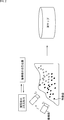
- FIG. 2 is a diagram for explaining the outline of SLAM.
- SLAM generates a 3D map of the surrounding environment from only the image from the image pickup unit or from the image and sensor information other than the image, and estimates the self-position (and posture) based on the image pickup unit in the 3D map. It is a technology that is performed in real time.
- SLAM is used to capture a 3D map of the surgical field including the surgical site (affected area) and the relative position of the endoscope 11 with respect to the surgical site (for example, imaging of the endoscope 11).
- Surgical support can be provided by acquiring the position of the portion or the position of the tip of the scope of the endoscope 11.
- the instructor instructs the surgeon during the operation on the surgical field image with a GUI (Graphical User Interface) to indicate the excision site, etc., or the surgical field image is taken before the operation by CT ( Computed Tomography)
- CT Computed Tomography
- the scope information (for example, the length information from the imaging unit to the tip of the scope and the shape information of the scope). It is preferable that the self-position is the tip of the scope based on the above.
- the scope information may be acquired by the CCU 13 as electrical information from the scope, or the CCU 13 estimates the type of the scope from the characteristics of the surgical field image, and the information associated with the scope estimated from the information stored in advance. May be read. Further, a point at a predetermined distance from the imaging unit or a point on the optical axis of the endoscope 11 may be set as the self-position.
- this medical system is applied to a microscope having an imaging unit, the relative position of the microscope (for example, the tip of the imaging unit of the microscope or the support portion that supports the imaging unit) is acquired.
- SLAM for example, feature points such as edges are detected from images taken by a moving imaging unit, and the corresponding feature points appearing in the images taken at different times t1 and t2 correspond to each other as corresponding points. Can be attached. Furthermore, in SLAM, the coordinates of the corresponding points in the 3D space are obtained, and the 3D shape of the subject, and eventually the imaging unit, takes a picture as a set (point cloud) of points represented by the coordinates of the 3D space of many corresponding points. A 3D map of 3D space is generated. Further, in SLAM, the self-position of the imaging unit is estimated by, for example, solving simultaneous equations based on the coordinates of the feature points.
- SLAM that uses the image taken by the imaging unit is called Visual SLAM.
- SLAM is described in, for example, Andrew J. Davison, “Real-Time Simultaneous Localization and Mapping with a Single Camera”, Proceedings of the 9th IEEE International Conference on Computer Vision Volume 2, 2003, pp.1403-1410. ..
- FIG. 3 is a diagram illustrating an example of surgical support using SLAM.
- the instructor gives an annotation on the surgical field image to instruct the excision site, etc. for instructing the surgeon according to the operation of the instructor. It can be drawn at the desired position.
- the annotation is displayed on the surgical field image. It can be displayed following the position instructed by the instructor.
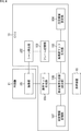
- FIG. 4 is a block diagram showing a first configuration example of the endoscope 11 and the CCU 13 of FIG.
- a 3D map used in an application such as drawing an annotation as described in FIG. 3 is desirable to have high accuracy from the viewpoint of safety.
- Multi-view stereo As an algorithm (calculation model) that generates a dense (point cloud) and high-precision 3D map using multi-viewpoint images.
- SfM Structure from Motion
- Multi-view stereo for example, Multi-View Stereo: A tutorial. Foundations and. TrendsR in Computer Graphics and Vision, vol. 9, no. 1-2, 2013, pp.1-148, Evaluation of multi- It is described in view 3D reconstruction software, CAIP 2015: Computer Analysis of Images and Patterns, pp.450-461.
- Multi-view stereo it is possible to generate dense and highly accurate 3D maps.
- Multi-view stereo is not suitable for applications that require real-time self-position estimation and 3D map generation (update) because of its high computational load and long processing time.
- a 3D map (3D information) of the surgical field is used as the first algorithm, for example, by Visual SLAM, using the surgical field image obtained by capturing the surgical field (the range to be) with the endoscope 11.
- Generation and self-position estimation are performed in real time.
- a 3D map of the region of interest is generated by a second algorithm different from the first algorithm, for example, Multi-view stereo.
- the endoscope 11 has an imaging unit 101, and the CCU 13 includes a scene detection unit 102, a frame storage unit 103, an attention area setting unit 104, a normal map generation unit 105, a high-precision map generation unit 106, and an operation. It has a front information storage unit 107 and a display image generation unit 108.
- the imaging unit 101 photographs the surgical field by receiving visible light from the surgical field, and outputs an RGB (Red, Green, Blue) image obtained by the photographing as a surgical field image.
- the surgical field image output by the imaging unit 101 is supplied to the scene detection unit 102 and the normal map generation unit 105. Further, the surgical field image output by the imaging unit 101 is normally supplied to the display image generation unit 108 via the map generation unit 105.
- the scene detection unit 102 detects an obstacle scene as a specific scene, for example, an obstacle to the generation of a 3D map, for each frame of the surgical field image from the imaging unit 101.
- an obstacle scene for example, there is a scene where there is bleeding, smoking, whiteout, or the like.
- the scene detection unit 102 limits the output of the frame of the surgical field image in which the obstacle scene is reflected to the frame storage unit 103. Therefore, the scene detection unit 102 does not output the frame of the surgical field image in which the obstacle scene is displayed to the frame storage unit 103.
- the scene detection unit 102 outputs the frame of the surgical field image to the frame storage unit 103.
- a method of detecting a bleeding scene as a disorder scene for example, there is a method of identifying a bleeding area only from an image by an image recognition technique or the like.
- a method of detecting a smoke scene as an obstacle scene for example, there is a method of detecting a cautery scene by an image recognition technology or the like.
- an overexposed scene as an obstacle scene for example, there is a method of detecting a scene where overexposure occurs or where overexposure is likely to occur by image recognition technology or the like.
- the frame storage unit 103 selects and stores a frame used for generating a high-precision map as a key frame from the frames of the surgical field image output by the scene detection unit 102.
- the frame of the surgical field image in which the obstacle scene is reflected is not output to the frame storage unit 103. Therefore, in the frame storage unit 103, among the frames of the surgical field image output by the imaging unit 101, the frames excluding the frame (specific frame) in which the obstacle scene is reflected, that is, the frame of the surgical field image in which the obstacle scene is not displayed.
- the selected frame is stored as a keyframe.
- the high-precision map generation unit 106 the keyframe of the surgical field image stored in the frame storage unit 103 is used, and as a second algorithm, for example, Multi-view.
- a high-precision map which is a high-precision (and dense) 3D map, is generated by SfM such as stereo.
- the high-precision map generation unit 106 in order to efficiently generate a high-precision map by Multi-view stereo, it is desirable that more images (frames) from different viewpoints exist as keyframes.
- the frame storage unit 103 determines the viewpoint (position) of the imaging unit 101 based on the trajectory of the imaging unit 101 of the endoscope 11 whose self-position is estimated by the map generation unit 105 and the change in the number of feature points in the surgical field. ) Is detected. Then, the frame storage unit 103 selects and stores keyframes such as an interval for selecting keyframes from the frames of the surgical field image output by the scene detection unit 102 according to the change in the viewpoint of the imaging unit 101. To switch.
- the frame storage unit 103 performs threshold processing on the amount of change in the viewpoint of the imaging unit 101 so that the viewpoint of the imaging unit 101 is in a steady (almost stopped) state or moves. Judge whether it is in the state of being.
- the frame storage unit 103 selects the latest frame output by the scene detection unit 102 as a key frame, and selects the key frame as a frame stored as a key frame in the past, for example, a frame stored as a key frame immediately before. Memorize by overwriting.
- the frame storage unit 103 selects and stores the frame output by the scene detection unit 102 as a key frame.
- the frame storage unit 103 can switch the frequency of keyframe selection according to the change in the viewpoint of the imaging unit 101.
- the maximum number of frames to be stored as key frames can be determined in advance.
- the new keyframe is stored by overwriting the oldest keyframe.
- the attention area setting unit 104 sets the attention area in (the frame) of the surgical field image.
- a part of the frame of the surgical field image can be set as the region of interest, or the entire area of the frame of the surgical field image can be set as the region of interest.
- the high-precision map generation unit 106 generates a high-precision map by Multi-view stereo.
- Multi-view stereo it is possible to generate a high-precision map, which is a high-precision (and dense) 3D map.
- Multi-view stereo has a high calculation load and takes a long processing time, if the entire frame is targeted by Multi-view stereo, real-time performance is hindered.
- an extremely high-speed device is required as the CCU 13, which increases the cost of the medical system.
- the attention area setting unit 104 even if the Multi-view stereo is executed for a long time, a part of the operative field image within the size that does not hinder the real-time property can be set as the attention area. Further, in the attention area setting unit 104, the entire area of the frame of the surgical field image can be set as a target of the multi-view stereo within a short time (for example, several seconds) that does not impair the real-time property. The entire area of the frame can be set as the area of interest.
- the attention area setting unit 104 only the operation part (the area in which the operation target is reflected) to be operated on can be set as the attention area in the surgical field image. Further, for example, in the attention area setting unit 104, the entire area of the frame of the surgical field image is set as the attention area in a short-time scene such as a few seconds when the organ is cut out by the electric knife as the energy treatment tool 22. Can be done.
- the attention area setting unit 104 can set the area required to be high-definition or the area estimated to be high-definition in the surgical field image as the area of interest.
- the area of interest can be set, for example, according to the designation of the surgeon.
- the operator can set the enclosed area as the area of interest by operating the UI (User Interface).
- the surgical field image displayed on the display device 15 is divided into a plurality of divided areas in advance, and the user specifies the divided area according to a voice (for example, "upper right" or "lower left”).
- the divided area designated by voice can be set as the area of interest.
- the line of sight of the operator who sees the surgical field image displayed on the display device 15 is detected, and the area including the position of interest of the operator estimated from the line of sight is set as the area of interest. Can be done.
- the area of interest can be set according to, for example, information obtained before surgery or information obtained during surgery.
- an object specified in advance can be recognized by object recognition using information obtained before surgery or information obtained during surgery, and a region of interest can be set using the recognition result of the object. ..
- a lesion site or a site to be operated on is specified in advance, and a normal map obtained by the normal map generation unit 105 or a high-precision display image generation unit 108 can be obtained.
- a normal map in which maps are integrated an area in which a predetermined portion and a shape are matched (an area in which a predetermined portion is reflected) can be set as a region of interest.
- the area of interest can be set according to the designation from a predetermined robot.
- the area designated by the scope holder robot can be set as the area of interest. ..
- the normal map generation unit 105 uses the surgical field image output by the imaging unit 101 to target the entire range reflected in the surgical field image, and uses SLAM such as Visual SLAM as the first algorithm to create a 3D map. Is generated and self-position estimation is performed.
- SLAM such as Visual SLAM
- the first algorithm is Visual-SLAM, which uses only images for 3D map generation and self-position estimation, and real-time performance, regardless of the degree of accuracy (and sparseness) of the points that make up the 3D map. It is possible to adopt a 3D map generation algorithm that can be secured.
- the first algorithm it is possible to adopt an algorithm that only generates a 3D map without performing self-position estimation.
- an algorithm that only generates a 3D map is adopted as the first algorithm, it is necessary to separately estimate the self-position.
- a 3D map is generated using an image and depth information output by a ToF sensor, Lidar, or the like.
- the algorithm to be used can be adopted.
- the 3D map generated by the normal map generation unit 105 in real time by the first algorithm is also referred to as a normal map.
- the normal map is a 3D map for recognizing the relative positional relationship between the 3D space captured by the imaging unit 101 and the self-position based on the imaging unit 101.
- the high-precision map generation unit 106 uses the key frame of the surgical field image stored in the frame storage unit 103 to target the attention area, and secondly As an algorithm of, for example, SfM such as Multi-view stereo is used to generate a 3D map, that is, to recognize the 3D shape of an object reflected in the region of interest.
- SfM such as Multi-view stereo
- a 3D map generation algorithm that can generate a 3D map with higher accuracy than a normal map can be adopted. Since the 3D map generated by the second algorithm is more accurate than the normal map generated by the first algorithm, the second algorithm has a high calculation load and requires a processing time. Conversely, as the first algorithm, an algorithm with a smaller amount of calculation than the second algorithm is adopted so as to ensure real-time performance.
- a normal map is generated for the entire range (surgical field) reflected in the surgical field image
- a 3D map is generated for only the region of interest.
- the second algorithm an algorithm that does not perform self-position estimation can be adopted.
- the second algorithm may be an algorithm that estimates the self-position.
- the 3D map with higher accuracy than the normal map generated by the high-precision map generation unit 106 by the second algorithm is also referred to as a high-precision map.
- the high-precision map expresses the 3D shape of the area of interest with higher definition than the normal map.
- Visual SLAM as the first algorithm can generate a 3D map (normal map) at a high frame rate, although the accuracy is lower than that of the second algorithm.
- Multi-view stereo as the second algorithm, it is difficult to generate a 3D map (high-precision map) at a high frame rate, but it is possible to generate a high-precision 3D map.
- the preoperative information storage unit 107 stores preoperative information obtained before surgery.
- the preoperative information is, for example, a 3D model constructed from CT images taken before surgery.
- the display image generation unit 108 functions as an integration unit that integrates the (sparse) normal map generated by the normal map generation unit 105 with the (dense) high-precision map generated by the high-precision map generation unit 106.
- the display image generation unit 108 that functions as an integration unit aligns the high-precision map (area of interest) with respect to the normal map, and integrates the high-precision map after the alignment into the normal map.
- a registration method such as Iterative closest point (ICP) can be adopted.
- the display image generation unit 108 deletes the high-precision map of the past attention area integrated with the normal map.
- the high-precision map of the new area of interest newly generated by the high-precision map generation unit 106 is integrated with the deleted normal map.
- the display image generation unit 108 includes a normal map after integration that integrates a high-precision map, and preoperative information stored in the preoperative information storage unit 107, if necessary. Is used to generate a display image to be displayed on the display device 15 and supply the display image to the display device 15.
- the display image generation unit 108 identifies a position in the 3D space in which the operator has instructed to display the annotation by using a normal map, and displays the surgical field image on which the annotation is drawn at that position. It can be generated as an image.
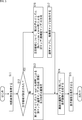
- FIG. 5 is a flowchart illustrating a first example of generating a normal map and a high-precision map by the CCU 13.
- step S11 the CCU 13 acquires a frame of the surgical field image sequentially output by the imaging unit 101.
- the frame of the surgical field image output by the imaging unit 101 is stored in the frame storage unit 103 as a key frame, if necessary, and the process proceeds from step S11 to step S12.
- step S12 in the CCU 13, the high-precision map generation unit 106 determines whether or not the attention area has been set by the attention area setting unit 104.
- step S12 If it is determined in step S12 that the region of interest is not set, the process proceeds to step S13.
- step S13 the normal map generation unit 105 uses the frame of the surgical field image output by the imaging unit 101 to generate (and update) the normal map by Visual SLAM as the first algorithm, and the imaging unit 101 self. Position estimation is performed, and the process proceeds to step S14.
- step S14 the display image generation unit 108 generates a display image using the latest normal map as needed, and the process proceeds to step S15.
- step S15 the display image generation unit 108 causes the display device 15 to display the display image.
- step S12 determines that the region of interest has been set. If it is determined in step S12 that the region of interest has been set, the process proceeds to step S16.
- step S16 the high-precision map generation unit 106 generates a high-precision map by Multi-view stereo as a second calculation algorithm only for the region of interest, and the process proceeds to step S17.
- step S17 the display image generation unit 108 integrates the latest high-precision map with the latest normal map. Then, the process proceeds from step S17 to step S14, and the above-mentioned process is performed below.
- the normal map is generated when the attention area is not set, and the normal map is not generated when the attention area is set.
- a high-precision map of only the area of interest is generated.
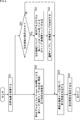
- FIG. 6 is a flowchart illustrating a second example of generating a normal map and a high-precision map by the CCU 13.
- step S21 the CCU 13 acquires a frame of the surgical field image output by the imaging unit 101 as in step S11 of FIG. 5, and stores it in the frame storage unit 103 as a key frame as needed. Then, the process proceeds in parallel from step S21 to step S22 and step S31.
- step S22 as in step S13 of FIG. 5, the normal map generation unit 105 uses the frame of the surgical field image output by the imaging unit 101 to generate a normal map by Visual SLAM as the first algorithm.
- the self-position estimation of the imaging unit 101 is performed, and the process proceeds to step S23.
- step S23 the display image generation unit 108 generates a display image using the latest normal map as needed, as in step S14 of FIG. 5, and the process proceeds to step S24.
- step S24 the display image generation unit 108 causes the display device 15 to display the display image in the same manner as in step S15 of FIG.
- step S31 in CCU 13, the high-precision map generation unit 106 determines whether or not the attention area has been set by the attention area setting unit 104, as in step S12 of FIG.
- step S31 If it is determined in step S31 that the region of interest is not set, the process skips steps S32 and S33 and proceeds to step S23.
- step S31 If it is determined in step S31 that the region of interest has been set, the process proceeds to step S32.
- step S32 the high-precision map generation unit 106 generates a high-precision map by Multi-view stereo as the second calculation algorithm only for the region of interest, as in step S16 of FIG. 5, and the process is a step. Proceed to S33.
- step S33 the display image generation unit 108 integrates the latest high-precision map into the latest normal map, as in step S17 of FIG. Then, the process proceeds from step S33 to step S23, and the above-mentioned process is performed below.
- the normal map is always generated regardless of whether or not the region of interest is set.
- the high-precision map is generated only when the region of interest is set, and only for that region of interest.
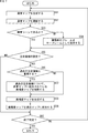
- FIG. 7 is a flowchart illustrating an example of signal processing performed by the CCU 13 of FIG.
- step S51 the normal map generation unit 105 uses the surgical field image output by the imaging unit 101 to generate a normal map and estimate its own position in real time by the first algorithm, which requires less calculation by the second algorithm. Is performed, and the process proceeds to step S52.
- step S52 the normal map generation unit 105 updates the normal map with the normal map generated in the immediately preceding step S51, and the process proceeds to step S53.
- step S53 the scene detection unit 102 determines whether or not the (latest) frame of the surgical field image output by the imaging unit 101 is an obstacle frame in which the obstacle scene is reflected.
- step S53 If it is determined in step S53 that the frame of the surgical field image output by the imaging unit 101 is not an obstacle frame, the process proceeds to step S54.
- step S54 the frame storage unit 103 stores a frame of the surgical field image that is not an obstacle frame as a key frame, if necessary, and the process proceeds to step S55.
- step S53 if it is determined in step S53 that the frame of the surgical field image output by the imaging unit 101 is an obstacle frame, the process skips step S54 and proceeds to step S55. Therefore, here, the fault frame is not stored in the frame storage unit 103.
- step S55 the high-precision map generation unit 106 determines whether or not the attention area has been set in the attention area setting unit 104.
- step S55 If it is determined in step S55 that the region of interest is not set, the process skips steps S56 to S59 and proceeds to step S60.
- step S55 If it is determined in step S55 that the region of interest has been set, the process proceeds to step S56.
- step S56 the display image generation unit 108 determines whether (a part or all) of the new attention area determined to be set in the immediately preceding step S55 overlaps with the past attention area.
- step S56 If it is determined in step S56 that the new attention area does not overlap with the past attention area, the process skips step S57 and proceeds to step S58.
- step S56 If it is determined in step S56 that the new area of interest overlaps with the area of interest in the past, the process proceeds to step S57.
- step S57 the display image generation unit 108 deletes the high-precision map of the past area of interest integrated into the normal map, and the process proceeds to step S58.
- step S58 the high-precision map generation unit 106 uses the keyframes stored in the frame storage unit 103 to obtain a high-precision map only for a new region of interest by the second algorithm with high precision by the first algorithm. The generation is performed, and the process proceeds to step S59.
- step S59 the high-precision map is integrated into the normal map, and the process proceeds to step S60.
- step S60 the CCU 13 determines whether or not to end the signal processing, and if it determines that the signal processing is not completed, the processing returns to step S51, and the same processing is repeated thereafter.
- step S60 when it is determined to end the signal processing, that is, when the medical system is operated so that the operator ends the signal processing, the CCU 13 ends the signal processing.
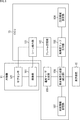
- FIG. 8 is a block diagram showing a second configuration example of the endoscope 11 and the CCU 13 of FIG.
- the endoscope 11 has an imaging unit 101 and a sub-sensor 121. Therefore, the endoscope 11 of FIG. 8 is common to the case of FIG. 4 in that it has an imaging unit 101. However, the endoscope 11 of FIG. 8 is different from the case of FIG. 4 in that the sub sensor 121 is newly provided.
- the CCU 13 includes a frame storage unit 103, a region of interest setting unit 104, a normal map generation unit 105, a high-precision map generation unit 106, a preoperative information storage unit 107, a display image generation unit 108, and a scene detection. It has a part 131. Therefore, the CCU 13 of FIG. 8 is common to the case of FIG. 4 in that it has a frame storage unit 103 to a display image generation unit 108. However, the CCU 13 of FIG. 8 is different from the case of FIG. 4 in that a scene detection unit 131 is provided instead of the scene detection unit 102.
- Visual SLAM as the first algorithm cannot detect sufficient feature points for the subject, and it is usually difficult to generate a map and estimate the self-position. become. In addition, it becomes difficult to generate the original 3D map for the part where blood adheres or the part hidden by smoke.
- the endoscope 11 is suitable for sensing an obstacle scene, apart from the imaging unit 101 as a sensor that senses (receives light) visible light and outputs an RGB surgical field image as the sensing result.
- a sub-sensor 121 that performs sensing under the same sensing conditions is provided.
- the scene detection unit 131 selects the surgical field image output by the imaging unit 101 or the sensing result output by the sub sensor 121 depending on whether or not it is an obstacle scene, and outputs it to the frame storage unit 103. ..
- the sub-sensor 121 is, for example, a sensor that senses light having a wavelength other than visible light, and outputs a sub-sensor image obtained by the sensing as a sensing result.
- the shooting method and lighting method when shooting the sub-sensor image with the sub-sensor 121 can be appropriately selected.
- a camera imaging unit
- a sensor capable of performing transmission observation by IR (Infrared), NBI (Narrow Band Imaging), etc.
- IR Infrared
- NBI Near Band Imaging
- a sub-sensor image can be taken by transmission observation using a special light observation technique that illuminates a subject with special light.
- a camera equipped with a polarizing filter such as a PL (Polarized Light) filter or ND (Neutral Density) filter is used as the subsensor 121 to capture a subsensor image in which overexposure is suppressed. Can be done.
- a polarizing filter such as a PL (Polarized Light) filter or ND (Neutral Density) filter
- the scene detection unit 131 detects an obstacle scene for each frame of the surgical field image from the imaging unit 101.
- the scene detection unit 131 When the obstacle scene is not detected, the scene detection unit 131 outputs a frame of the surgical field image (the obstacle scene is not shown) to the frame storage unit 103 in the same manner as the scene detection unit 102.
- the scene detection unit 131 outputs the frame of the sub-sensor image output by the sub-sensor 121 to the frame storage unit 103 for the frame in which the failure scene is displayed.
- the frame storage unit 103 the frame of the sub-sensor image output by the sub-sensor 121 can be stored as a key frame for the frame in which the failure scene is displayed.
- the high-precision map generation unit 106 can stably generate a high-precision map of the region of interest even for an obstacle scene.
- the normal map generation unit 105 can generate a normal map and estimate its own position by always using the RGB surgical field image output by the imaging unit 101 regardless of whether or not it is an obstacle scene. Further, the normal map generation unit 105 generates a normal map and estimates the self-position using the RGB surgical field image output by the imaging unit 101 when it is not an obstacle scene, and when it is an obstacle scene, it generates a normal map and estimates the self-position. Using the sub-sensor image output by the sub-sensor 121, it is possible to generate a normal map and estimate the self-position.
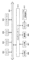
- FIG. 9 is a flowchart illustrating an example of signal processing performed by the CCU 13 of FIG.
- steps S71 to S74 the same processing as in steps S51 to S54 of FIG. 7 is performed, respectively.
- step S73 corresponding to step S53 of FIG. 7, if the frame of the surgical field image output by the imaging unit 101 is determined to be an obstacle frame, the process proceeds to step S91.
- step S91 the frame storage unit 103 stores, if necessary, the frame of the sub-sensor image output by the sub-sensor 121 as a key frame for the obstacle frame in which the obstacle scene is reflected in the surgical field image output by the imaging unit 101.
- the process proceeds to step S75.
- steps S75 to S80 the same processing as in steps S55 to S60 of FIG. 7 is performed.
- the entire frame in which the obstacle scene is displayed can be set as the area of interest.
- the obstacle scene is short, it is possible to generate a high-precision map that accurately expresses the part that is difficult to see in the RGB surgical field image due to the obstacle while maintaining the real-time property.
- the first A second algorithm which is different from the algorithm of, generates a high-precision map as a 3D map of the region of interest. Therefore, for example, as the first algorithm, a 3D map with a small amount of calculation and real-time performance can be generated. Attention is paid to the real-time property of 3D map generation (and self-position estimation) by adopting an algorithm and a generation algorithm that can generate a highly accurate 3D map as the second algorithm. For regions, it is possible to generate a highly accurate 3D map. As a result, it is possible to provide the operator with accurate and stable information as the information obtained by using the 3D map.
- the area of interest can be a scene such as a bleeding scene or a smoke scene that has an obstacle in generating a 3D map using an RGB surgical field image. Even if it is included, a highly accurate 3D map can be generated for the area of interest.
- the series of processes of the CCU 13 described above can be performed by hardware or software.
- the programs constituting the software are installed on a general-purpose computer or the like.
- FIG. 10 is a block diagram showing a configuration example of an embodiment of a computer in which a program for executing the above-mentioned series of processes is installed.
- the program can be recorded in advance on the hard disk 905 or ROM 903 as a recording medium built in the computer.
- the program can be stored (recorded) in the removable recording medium 911 driven by the drive 909.
- a removable recording medium 911 can be provided as so-called package software.
- examples of the removable recording medium 911 include a flexible disk, a CD-ROM (Compact Disc Read Only Memory), an MO (Magneto Optical) disk, a DVD (Digital Versatile Disc), a magnetic disk, and a semiconductor memory.
- the program can be downloaded to the computer via a communication network or a broadcasting network and installed on the built-in hard disk 905. That is, for example, the program transfers wirelessly from a download site to a computer via an artificial satellite for digital satellite broadcasting, or transfers to a computer by wire via a network such as LAN (Local Area Network) or the Internet. be able to.
- LAN Local Area Network
- the computer has a built-in CPU (Central Processing Unit) 902, and the input / output interface 910 is connected to the CPU 902 via the bus 901.
- CPU Central Processing Unit
- the CPU 902 executes a program stored in the ROM (Read Only Memory) 903 accordingly. .. Alternatively, the CPU 902 loads the program stored in the hard disk 905 into the RAM (Random Access Memory) 904 and executes it.
- ROM Read Only Memory
- the CPU 902 performs processing according to the above-mentioned flowchart or processing performed according to the above-mentioned block diagram configuration. Then, the CPU 902 outputs the processing result from the output unit 906 or transmits it from the communication unit 908, and further records it on the hard disk 905, if necessary, via the input / output interface 910.
- the input unit 907 is composed of a keyboard, a mouse, a microphone, and the like. Further, the output unit 906 is composed of an LCD (Liquid Crystal Display), a speaker, or the like.
- LCD Liquid Crystal Display
- the processing performed by the computer according to the program does not necessarily have to be performed in chronological order in the order described as the flowchart. That is, the processing performed by the computer according to the program also includes processing executed in parallel or individually (for example, parallel processing or processing by an object).
- the program may be processed by one computer (processor) or may be distributed processed by a plurality of computers. Further, the program may be transferred to a distant computer and executed.
- the system means a set of a plurality of components (devices, modules (parts), etc.), and it does not matter whether all the components are in the same housing. Therefore, a plurality of devices housed in separate housings and connected via a network, and a device in which a plurality of modules are housed in one housing are both systems. ..
- this technology can have a cloud computing configuration in which one function is shared by a plurality of devices via a network and processed jointly.
- each step described in the above flowchart can be executed by one device or can be shared and executed by a plurality of devices.
- one step includes a plurality of processes
- the plurality of processes included in the one step can be executed by one device or shared by a plurality of devices.
- ⁇ 1> An imaging unit that captures the surgical field and outputs the surgical field image, Using the surgical field image, a first generation unit that generates 3D information of the surgical field by the first algorithm, and A medical system including a second generation unit that generates 3D information of the region of interest by a second algorithm different from the first algorithm when a region of interest is set in the surgical field image.
- the second algorithm is an algorithm that generates 3D information with higher accuracy than the first algorithm.
- ⁇ 3> The medical system according to ⁇ 1> or ⁇ 2>, further comprising an integration unit that integrates the 3D information generated by the second algorithm into the 3D information generated by the first algorithm.
- the integration unit aligns the 3D information generated by the second algorithm with respect to the 3D information generated by the first algorithm, and obtains the 3D information generated by the second algorithm.
- the medical system according to ⁇ 3> which integrates into the 3D information generated by the first algorithm.
- the integration unit deletes the past 3D information of the attention area integrated with the 3D information generated by the first algorithm, and newly generates the integration unit.
- the medical system according to ⁇ 3> or ⁇ 4> which integrates the 3D information of the region of interest.
- ⁇ 6> The medical system according to any one of ⁇ 1> to ⁇ 5>, wherein the first algorithm is an algorithm that generates 3D information and estimates a self-position based on the imaging unit.
- the first algorithm is Visual-SLAM.
- the second algorithm is an algorithm that does not perform self-position estimation.
- the second algorithm is a multi-view stereo.
- ⁇ 10> The medical system according to any one of ⁇ 1> to ⁇ 9>, wherein the first algorithm is an algorithm having a smaller amount of calculation than the second algorithm.
- the second generation unit generates 3D information by the second algorithm using keyframes selected from the frames of the surgical field image output by the imaging unit ⁇ 1> to ⁇ 10>.
- ⁇ 12> A scene detection unit that detects a specific frame in which a specific scene appears from the frame of the surgical field image is further provided.
- the second generation unit generates 3D information by the second algorithm using the key frame selected from the frames other than the specific frame among the frames of the surgical field image ⁇ 11>.
- ⁇ 13> The medical system according to ⁇ 11> or ⁇ 12>, wherein the frequency of selection of the key frame is switched according to a change in the position of the imaging unit.
- ⁇ 14> The medical system according to any one of ⁇ 1> to ⁇ 13>, further comprising a region of interest setting unit for setting the region of interest.
- ⁇ 15> The medical system according to ⁇ 14>, wherein the attention area setting unit sets the attention area according to a designation from a user.
- ⁇ 16> The medical system according to ⁇ 14> or ⁇ 15>, wherein the attention area setting unit sets the attention area according to the output of a predetermined robot.
- ⁇ 17> The medical system according to any one of ⁇ 14> to ⁇ 16>, wherein the attention area setting unit sets a region in which a predetermined portion is reflected, and sets the attention area.
- a first generation unit that generates 3D information of the surgical field by the first algorithm using the surgical field image obtained by capturing the surgical field
- a signal processing device including a second generation unit that generates 3D information of the region of interest by a second algorithm different from the first algorithm when a region of interest is set in the surgical field image.
- the 3D information of the surgical field is generated by the first algorithm, and A signal processing method including generating 3D information of the region of interest by a second algorithm different from the first algorithm when a region of interest is set in the surgical field image.
Landscapes
- Engineering & Computer Science (AREA)
- Health & Medical Sciences (AREA)
- Physics & Mathematics (AREA)
- General Physics & Mathematics (AREA)
- Theoretical Computer Science (AREA)
- Nuclear Medicine, Radiotherapy & Molecular Imaging (AREA)
- Radiology & Medical Imaging (AREA)
- Medical Informatics (AREA)
- Computer Vision & Pattern Recognition (AREA)
- General Health & Medical Sciences (AREA)
- Public Health (AREA)
- Life Sciences & Earth Sciences (AREA)
- Epidemiology (AREA)
- Primary Health Care (AREA)
- Surgery (AREA)
- Quality & Reliability (AREA)
- Biophysics (AREA)
- Optics & Photonics (AREA)
- Pathology (AREA)
- Biomedical Technology (AREA)
- Heart & Thoracic Surgery (AREA)
- Molecular Biology (AREA)
- Animal Behavior & Ethology (AREA)
- Veterinary Medicine (AREA)
- Endoscopes (AREA)
Abstract
Priority Applications (2)
| Application Number | Priority Date | Filing Date | Title |
|---|---|---|---|
| JP2021509023A JP7517325B2 (ja) | 2019-03-25 | 2020-03-12 | 医療システム、信号処理装置、及び、信号処理方法 |
| US17/437,533 US12266127B2 (en) | 2019-03-25 | 2020-03-12 | Medical system, signal processing device, and signal processing method |
Applications Claiming Priority (2)
| Application Number | Priority Date | Filing Date | Title |
|---|---|---|---|
| JP2019056683 | 2019-03-25 | ||
| JP2019-056683 | 2019-03-25 |
Publications (1)
| Publication Number | Publication Date |
|---|---|
| WO2020195877A1 true WO2020195877A1 (fr) | 2020-10-01 |
Family
ID=72609809
Family Applications (1)
| Application Number | Title | Priority Date | Filing Date |
|---|---|---|---|
| PCT/JP2020/010741 Ceased WO2020195877A1 (fr) | 2019-03-25 | 2020-03-12 | Système médical, dispositif de traitement du signal et procédé de traitement du signal |
Country Status (3)
| Country | Link |
|---|---|
| US (1) | US12266127B2 (fr) |
| JP (1) | JP7517325B2 (fr) |
| WO (1) | WO2020195877A1 (fr) |
Cited By (2)
| Publication number | Priority date | Publication date | Assignee | Title |
|---|---|---|---|---|
| JP2024028512A (ja) * | 2020-10-02 | 2024-03-04 | Hoya株式会社 | プログラム、情報処理方法及び内視鏡システム |
| WO2025009009A1 (fr) * | 2023-07-03 | 2025-01-09 | オリンパスメディカルシステムズ株式会社 | Dispositif de traitement d'images, procédé de traitement d'images, et programme de traitement d'images |
Citations (4)
| Publication number | Priority date | Publication date | Assignee | Title |
|---|---|---|---|---|
| JP2015213753A (ja) * | 2014-05-08 | 2015-12-03 | 三星電子株式会社Samsung Electronics Co.,Ltd. | 手術ロボット及びその制御方法 |
| WO2017057330A1 (fr) * | 2015-09-28 | 2017-04-06 | オリンパス株式会社 | Système d'endoscope et procédé de traitement d'image |
| JP2018124984A (ja) * | 2016-12-01 | 2018-08-09 | トムソン ライセンシングThomson Licensing | モバイル装置の環境の3d再構成のための方法および対応するコンピュータ・プログラム・プロダクトおよび装置 |
| WO2018216342A1 (fr) * | 2017-05-24 | 2018-11-29 | ソニー株式会社 | Appareil de traitement d'informations, procédé de traitement d'informations et programme |
Family Cites Families (15)
| Publication number | Priority date | Publication date | Assignee | Title |
|---|---|---|---|---|
| US6961404B2 (en) | 2002-09-26 | 2005-11-01 | Eastman Kodak Company | Method and system for reconstructing an image from projection data acquired by a cone beam computed tomography system |
| US7872235B2 (en) * | 2005-01-13 | 2011-01-18 | Spectrum Dynamics Llc | Multi-dimensional image reconstruction and analysis for expert-system diagnosis |
| US20140193336A1 (en) * | 2005-07-19 | 2014-07-10 | Biosensors International Group, Ltd. | Imaging protocols |
| US7324904B2 (en) * | 2005-12-21 | 2008-01-29 | Weyerhauser Company | Methods for determining dimensional stability of wood products utilizing single and multiple sensor groups |
| US8401258B2 (en) | 2007-03-16 | 2013-03-19 | Sti Medical Systems, Llc | Method to provide automated quality feedback to imaging devices to achieve standardized imaging data |
| US8254656B2 (en) * | 2009-10-13 | 2012-08-28 | Morpho Detection, Inc. | Methods and system for selective resolution improvement in computed tomography |
| EP2633495A1 (fr) * | 2010-10-25 | 2013-09-04 | Koninklijke Philips Electronics N.V. | Système de segmentation d'une image médicale |
| US20130009980A1 (en) * | 2011-07-07 | 2013-01-10 | Ati Technologies Ulc | Viewing-focus oriented image processing |
| US20150078642A1 (en) * | 2012-04-24 | 2015-03-19 | The General Hospital Corporation | Method and system for non-invasive quantification of biologial sample physiology using a series of images |
| JP6017743B1 (ja) | 2014-12-15 | 2016-11-02 | オリンパス株式会社 | 医療機器システム、医療機器システムの作動方法 |
| US20180038807A1 (en) * | 2016-08-08 | 2018-02-08 | Adaptix Ltd. | Method and system for reconstructing 3-dimensional images from spatially and temporally overlapping x-rays |
| EP3343506A1 (fr) * | 2016-12-28 | 2018-07-04 | Thomson Licensing | Procédé et dispositif de segmentation et reconstruction collaboratives d'une scène en 3d |
| WO2018129715A1 (fr) * | 2017-01-13 | 2018-07-19 | 浙江大学 | Procédé de reconstruction tridimensionnelle dense et de positionnement simultané |
| JP2019162339A (ja) * | 2018-03-20 | 2019-09-26 | ソニー株式会社 | 手術支援システムおよび表示方法 |
| WO2021092397A1 (fr) * | 2019-11-08 | 2021-05-14 | General Electric Company | Système et procédé de modélisation de végétation utilisant une imagerie par satellite et/ou une imagerie aérienne |
-
2020
- 2020-03-12 WO PCT/JP2020/010741 patent/WO2020195877A1/fr not_active Ceased
- 2020-03-12 JP JP2021509023A patent/JP7517325B2/ja active Active
- 2020-03-12 US US17/437,533 patent/US12266127B2/en active Active
Patent Citations (4)
| Publication number | Priority date | Publication date | Assignee | Title |
|---|---|---|---|---|
| JP2015213753A (ja) * | 2014-05-08 | 2015-12-03 | 三星電子株式会社Samsung Electronics Co.,Ltd. | 手術ロボット及びその制御方法 |
| WO2017057330A1 (fr) * | 2015-09-28 | 2017-04-06 | オリンパス株式会社 | Système d'endoscope et procédé de traitement d'image |
| JP2018124984A (ja) * | 2016-12-01 | 2018-08-09 | トムソン ライセンシングThomson Licensing | モバイル装置の環境の3d再構成のための方法および対応するコンピュータ・プログラム・プロダクトおよび装置 |
| WO2018216342A1 (fr) * | 2017-05-24 | 2018-11-29 | ソニー株式会社 | Appareil de traitement d'informations, procédé de traitement d'informations et programme |
Cited By (3)
| Publication number | Priority date | Publication date | Assignee | Title |
|---|---|---|---|---|
| JP2024028512A (ja) * | 2020-10-02 | 2024-03-04 | Hoya株式会社 | プログラム、情報処理方法及び内視鏡システム |
| JP7562886B2 (ja) | 2020-10-02 | 2024-10-07 | Hoya株式会社 | プログラム、情報処理方法及び内視鏡システム |
| WO2025009009A1 (fr) * | 2023-07-03 | 2025-01-09 | オリンパスメディカルシステムズ株式会社 | Dispositif de traitement d'images, procédé de traitement d'images, et programme de traitement d'images |
Also Published As
| Publication number | Publication date |
|---|---|
| US12266127B2 (en) | 2025-04-01 |
| US20220148209A1 (en) | 2022-05-12 |
| JP7517325B2 (ja) | 2024-07-17 |
| JPWO2020195877A1 (fr) | 2020-10-01 |
Similar Documents
| Publication | Publication Date | Title |
|---|---|---|
| US20210015343A1 (en) | Surgical assistance apparatus, surgical method, non-transitory computer readable medium and surgical assistance system | |
| US11269173B2 (en) | Systems and methods for displaying medical video images and/or medical 3D models | |
| JP7127785B2 (ja) | 情報処理システム、内視鏡システム、学習済みモデル、情報記憶媒体及び情報処理方法 | |
| EP3463032B1 (fr) | Fusion à base d'image endoscopique et d'images échographiques | |
| US9289267B2 (en) | Method and apparatus for minimally invasive surgery using endoscopes | |
| CN111031958B (zh) | 在微创手术期间合成多个相机视点之间的空间感知过渡 | |
| JP4861540B2 (ja) | 医療装置 | |
| CN112672709A (zh) | 用于跟踪机器人操纵的手术器械的位置的系统和方法 | |
| CN113993478B (zh) | 医疗工具控制系统、控制器和非暂时性计算机可读存储器 | |
| JP2012525190A (ja) | 単眼の内視鏡画像からのリアルタイム深度推定 | |
| JP7770392B2 (ja) | 医療処置中に未検査領域を識別するためのデバイス、システム、及び方法 | |
| JP2023507063A (ja) | 手術中に画像取込装置を制御するための方法、装置、およびシステム | |
| CN110099599A (zh) | 医学图像处理设备、医学图像处理方法和程序 | |
| JP7810655B2 (ja) | ビデオにおけるコンピュータ支援の標識または基準配置のシステムおよび方法 | |
| US20250268666A1 (en) | Systems and methods for providing surgical assistance based on operational context | |
| WO2016072288A1 (fr) | Dispositif endoscopique, son procédé de fonctionnement, et programme | |
| US20230215059A1 (en) | Three-dimensional model reconstruction | |
| WO2018221068A1 (fr) | Dispositif, procédé et programme de traitement d'informations | |
| EP3782529A1 (fr) | Systèmes et procédés permettant de faire varier les résolutions de manière sélective | |
| JP7517325B2 (ja) | 医療システム、信号処理装置、及び、信号処理方法 | |
| CN114126531B (zh) | 医疗成像系统、医疗成像处理方法及医疗信息处理设备 | |
| JP2020534050A (ja) | ロボット外科手技中に立体視知覚通知および/または推奨事項を提供するためのシステム、方法、およびコンピュータ可読媒体 | |
| US20250127382A1 (en) | Medical observation system, method, and medical observation device | |
| WO2023203908A1 (fr) | Système d'assistance chirurgicale et dispositif d'assistance chirurgicale | |
| WO2022219878A1 (fr) | Système d'observation médicale, procédé de traitement d'image médicale et dispositif de traitement d'informations |
Legal Events
| Date | Code | Title | Description |
|---|---|---|---|
| 121 | Ep: the epo has been informed by wipo that ep was designated in this application |
Ref document number: 20779151 Country of ref document: EP Kind code of ref document: A1 |
|
| ENP | Entry into the national phase |
Ref document number: 2021509023 Country of ref document: JP Kind code of ref document: A |
|
| NENP | Non-entry into the national phase |
Ref country code: DE |
|
| 122 | Ep: pct application non-entry in european phase |
Ref document number: 20779151 Country of ref document: EP Kind code of ref document: A1 |
|
| WWG | Wipo information: grant in national office |
Ref document number: 17437533 Country of ref document: US |