WO2020196026A1 - Dispositif de commande d'imagerie, procédé de commande d'imagerie, programme et système d'imagerie - Google Patents
Dispositif de commande d'imagerie, procédé de commande d'imagerie, programme et système d'imagerie Download PDFInfo
- Publication number
- WO2020196026A1 WO2020196026A1 PCT/JP2020/011447 JP2020011447W WO2020196026A1 WO 2020196026 A1 WO2020196026 A1 WO 2020196026A1 JP 2020011447 W JP2020011447 W JP 2020011447W WO 2020196026 A1 WO2020196026 A1 WO 2020196026A1
- Authority
- WO
- WIPO (PCT)
- Prior art keywords
- optical member
- point
- rotation
- axis
- rotation axis
- Prior art date
- Legal status (The legal status is an assumption and is not a legal conclusion. Google has not performed a legal analysis and makes no representation as to the accuracy of the status listed.)
- Ceased
Links
- 0 CCI(C[C@@](C)I)II1*CCC1 Chemical compound CCI(C[C@@](C)I)II1*CCC1 0.000 description 1
Images


Classifications
-
- A—HUMAN NECESSITIES
- A61—MEDICAL OR VETERINARY SCIENCE; HYGIENE
- A61B—DIAGNOSIS; SURGERY; IDENTIFICATION
- A61B1/00—Instruments for performing medical examinations of the interior of cavities or tubes of the body by visual or photographical inspection, e.g. endoscopes; Illuminating arrangements therefor
- A61B1/00147—Holding or positioning arrangements
-
- A—HUMAN NECESSITIES
- A61—MEDICAL OR VETERINARY SCIENCE; HYGIENE
- A61B—DIAGNOSIS; SURGERY; IDENTIFICATION
- A61B1/00—Instruments for performing medical examinations of the interior of cavities or tubes of the body by visual or photographical inspection, e.g. endoscopes; Illuminating arrangements therefor
- A61B1/00163—Optical arrangements
- A61B1/00174—Optical arrangements characterised by the viewing angles
- A61B1/00179—Optical arrangements characterised by the viewing angles for off-axis viewing
-
- A—HUMAN NECESSITIES
- A61—MEDICAL OR VETERINARY SCIENCE; HYGIENE
- A61B—DIAGNOSIS; SURGERY; IDENTIFICATION
- A61B1/00—Instruments for performing medical examinations of the interior of cavities or tubes of the body by visual or photographical inspection, e.g. endoscopes; Illuminating arrangements therefor
- A61B1/00002—Operational features of endoscopes
- A61B1/00004—Operational features of endoscopes characterised by electronic signal processing
- A61B1/00006—Operational features of endoscopes characterised by electronic signal processing of control signals
-
- A—HUMAN NECESSITIES
- A61—MEDICAL OR VETERINARY SCIENCE; HYGIENE
- A61B—DIAGNOSIS; SURGERY; IDENTIFICATION
- A61B1/00—Instruments for performing medical examinations of the interior of cavities or tubes of the body by visual or photographical inspection, e.g. endoscopes; Illuminating arrangements therefor
- A61B1/00002—Operational features of endoscopes
- A61B1/00004—Operational features of endoscopes characterised by electronic signal processing
- A61B1/00009—Operational features of endoscopes characterised by electronic signal processing of image signals during a use of endoscope
-
- A—HUMAN NECESSITIES
- A61—MEDICAL OR VETERINARY SCIENCE; HYGIENE
- A61B—DIAGNOSIS; SURGERY; IDENTIFICATION
- A61B1/00—Instruments for performing medical examinations of the interior of cavities or tubes of the body by visual or photographical inspection, e.g. endoscopes; Illuminating arrangements therefor
- A61B1/00147—Holding or positioning arrangements
- A61B1/00149—Holding or positioning arrangements using articulated arms
-
- A—HUMAN NECESSITIES
- A61—MEDICAL OR VETERINARY SCIENCE; HYGIENE
- A61B—DIAGNOSIS; SURGERY; IDENTIFICATION
- A61B1/00—Instruments for performing medical examinations of the interior of cavities or tubes of the body by visual or photographical inspection, e.g. endoscopes; Illuminating arrangements therefor
- A61B1/005—Flexible endoscopes
-
- A—HUMAN NECESSITIES
- A61—MEDICAL OR VETERINARY SCIENCE; HYGIENE
- A61B—DIAGNOSIS; SURGERY; IDENTIFICATION
- A61B1/00—Instruments for performing medical examinations of the interior of cavities or tubes of the body by visual or photographical inspection, e.g. endoscopes; Illuminating arrangements therefor
- A61B1/04—Instruments for performing medical examinations of the interior of cavities or tubes of the body by visual or photographical inspection, e.g. endoscopes; Illuminating arrangements therefor combined with photographic or television appliances
- A61B1/045—Control thereof
-
- A—HUMAN NECESSITIES
- A61—MEDICAL OR VETERINARY SCIENCE; HYGIENE
- A61B—DIAGNOSIS; SURGERY; IDENTIFICATION
- A61B1/00—Instruments for performing medical examinations of the interior of cavities or tubes of the body by visual or photographical inspection, e.g. endoscopes; Illuminating arrangements therefor
- A61B1/04—Instruments for performing medical examinations of the interior of cavities or tubes of the body by visual or photographical inspection, e.g. endoscopes; Illuminating arrangements therefor combined with photographic or television appliances
- A61B1/05—Instruments for performing medical examinations of the interior of cavities or tubes of the body by visual or photographical inspection, e.g. endoscopes; Illuminating arrangements therefor combined with photographic or television appliances characterised by the image sensor, e.g. camera, being in the distal end portion
-
- A—HUMAN NECESSITIES
- A61—MEDICAL OR VETERINARY SCIENCE; HYGIENE
- A61B—DIAGNOSIS; SURGERY; IDENTIFICATION
- A61B34/00—Computer-aided surgery; Manipulators or robots specially adapted for use in surgery
- A61B34/30—Surgical robots
-
- A—HUMAN NECESSITIES
- A61—MEDICAL OR VETERINARY SCIENCE; HYGIENE
- A61B—DIAGNOSIS; SURGERY; IDENTIFICATION
- A61B90/00—Instruments, implements or accessories specially adapted for surgery or diagnosis and not covered by any of the groups A61B1/00 - A61B50/00, e.g. for luxation treatment or for protecting wound edges
- A61B90/36—Image-producing devices or illumination devices not otherwise provided for
- A61B90/37—Surgical systems with images on a monitor during operation
-
- G—PHYSICS
- G03—PHOTOGRAPHY; CINEMATOGRAPHY; ANALOGOUS TECHNIQUES USING WAVES OTHER THAN OPTICAL WAVES; ELECTROGRAPHY; HOLOGRAPHY
- G03B—APPARATUS OR ARRANGEMENTS FOR TAKING PHOTOGRAPHS OR FOR PROJECTING OR VIEWING THEM; APPARATUS OR ARRANGEMENTS EMPLOYING ANALOGOUS TECHNIQUES USING WAVES OTHER THAN OPTICAL WAVES; ACCESSORIES THEREFOR
- G03B17/00—Details of cameras or camera bodies; Accessories therefor
- G03B17/56—Accessories
- G03B17/561—Support related camera accessories
-
- G—PHYSICS
- G03—PHOTOGRAPHY; CINEMATOGRAPHY; ANALOGOUS TECHNIQUES USING WAVES OTHER THAN OPTICAL WAVES; ELECTROGRAPHY; HOLOGRAPHY
- G03B—APPARATUS OR ARRANGEMENTS FOR TAKING PHOTOGRAPHS OR FOR PROJECTING OR VIEWING THEM; APPARATUS OR ARRANGEMENTS EMPLOYING ANALOGOUS TECHNIQUES USING WAVES OTHER THAN OPTICAL WAVES; ACCESSORIES THEREFOR
- G03B37/00—Panoramic or wide-screen photography; Photographing extended surfaces, e.g. for surveying; Photographing internal surfaces, e.g. of pipe
- G03B37/005—Photographing internal surfaces, e.g. of pipe
-
- A—HUMAN NECESSITIES
- A61—MEDICAL OR VETERINARY SCIENCE; HYGIENE
- A61B—DIAGNOSIS; SURGERY; IDENTIFICATION
- A61B34/00—Computer-aided surgery; Manipulators or robots specially adapted for use in surgery
- A61B34/20—Surgical navigation systems; Devices for tracking or guiding surgical instruments, e.g. for frameless stereotaxis
- A61B2034/2046—Tracking techniques
- A61B2034/2065—Tracking using image or pattern recognition
-
- A—HUMAN NECESSITIES
- A61—MEDICAL OR VETERINARY SCIENCE; HYGIENE
- A61B—DIAGNOSIS; SURGERY; IDENTIFICATION
- A61B34/00—Computer-aided surgery; Manipulators or robots specially adapted for use in surgery
- A61B34/30—Surgical robots
- A61B2034/301—Surgical robots for introducing or steering flexible instruments inserted into the body, e.g. catheters or endoscopes
-
- A—HUMAN NECESSITIES
- A61—MEDICAL OR VETERINARY SCIENCE; HYGIENE
- A61B—DIAGNOSIS; SURGERY; IDENTIFICATION
- A61B90/00—Instruments, implements or accessories specially adapted for surgery or diagnosis and not covered by any of the groups A61B1/00 - A61B50/00, e.g. for luxation treatment or for protecting wound edges
- A61B90/36—Image-producing devices or illumination devices not otherwise provided for
- A61B90/37—Surgical systems with images on a monitor during operation
- A61B2090/371—Surgical systems with images on a monitor during operation with simultaneous use of two cameras
Definitions
- the present technology relates to an imaging control device, an imaging control method, a program, and an imaging system, and is particularly suitable for imaging control when imaging is performed using an optical member whose observation optical axis is tilted with respect to the central axis. It relates to an apparatus, a shooting control method, a program, and a shooting system.
- a squint mirror capable of photographing an angle inclined with respect to the central axis has been used for an insertion part of an endoscope system into a living body.
- the subject can be photographed from a different angle by rotating the squint mirror and changing the direction of the observation window at the tip of the squint mirror.
- the area of interest moves to the edge of the image or goes out of the angle of view, and the area of interest to the user. You may lose sight of it. Therefore, when rotating the perspective mirror, the user needs to carefully adjust the angle of the perspective mirror and the like while checking the image so as not to lose sight of the region of interest.
- Patent Document 1 a method of rotating the insertion portion so that the observation optical axis of the insertion portion draws a conical trajectory with a point on the affected part of the patient as the apex has been proposed (for example, Patent Document 1). reference).
- This technology was made in view of such a situation, and when shooting with an optical member whose observation optical axis is tilted with respect to the central axis, the direction in which the subject is shot can be easily changed. It allows you to do it.
- the imaging control device on the first side surface of the present technology serves as a fulcrum of a rod-shaped optical member whose observation optical axis is tilted with respect to the central axis, and is a pivot point that is not on the observation optical axis and a point of interest on the subject.
- a rotation axis setting unit for setting the rotation axis and an attitude control unit for rotating the optical member around the rotation axis are provided based on the above.
- the imaging control device serves as a fulcrum of a rod-shaped optical member whose observation optical axis is tilted with respect to the central axis, and a pivot point that is not on the observation optical axis, and A rotation axis is set based on a point of interest on the subject, and the optical member is rotated about the rotation axis.
- the program of the first aspect of the present technology serves as a fulcrum of a rod-shaped optical member whose observation optical axis is tilted with respect to the central axis, and is based on a pivot point that is not on the observation optical axis and a point of interest on the subject. Then, the rotation axis is set, and the computer is made to execute the process of rotating the optical member around the rotation axis.
- the imaging system on the second side of the present technology includes an imaging unit including a rod-shaped optical member whose observation optical axis is tilted with respect to the central axis, and a pivot point that serves as a fulcrum of the optical member and is not on the observation optical axis.
- a rotation axis setting unit that sets a rotation axis based on a point of interest on the subject, and an attitude control unit that rotates the optical member around the rotation axis are provided.
- the observation optical axis serves as a fulcrum of a rod-shaped optical member tilted with respect to the central axis, and is based on a pivot point that is not on the observation optical axis and a point of interest on the subject.
- the rotation axis is set, and the optical member is rotated around the rotation axis.
- a pivot point that serves as a fulcrum of the optical member of the photographing unit including a rod-shaped optical member whose observation optical axis is tilted with respect to the central axis, and a pivot point that is not on the observation optical axis, and A rotation axis is set based on a point of interest on the subject, and the optical member is rotated about the rotation axis.
- FIG. 1 shows a configuration example of a photographing system 11 to which the present technology is applied.
- the imaging system 11 is, for example, an endoscope system used in the medical field, and is used for imaging and observation in a living body.
- the photographing system 11 includes an input unit 21, a photographing control unit 22, an imaging unit 23, an image processing unit 24, a display unit 25, and an arm mechanism 26.
- the input unit 21 includes operation devices such as buttons, switches, and a touch panel, and accepts operations by the user.
- the input unit 21 supplies the input signal input by the user operation to the photographing control unit 22.
- the shooting control unit 22 controls the shooting of the subject by the shooting unit 23.
- the shooting control unit 22 includes a shooting processing control unit 31 and a shooting posture control unit 32.
- the shooting processing control unit 31 controls the shooting processing (for example, shooting timing, etc.) of the shooting unit 23 based on the input signal supplied from the input unit 21 and the shot image supplied from the shooting unit 23, and , Set various shooting parameters.
- the shooting posture control unit 32 controls the shooting unit 23 and the arm mechanism 26 based on the input signal supplied from the input unit 21, the shooting image supplied from the shooting unit 23, and the like, thereby causing the shooting unit 23 to control the shooting unit 23.
- the posture (hereinafter referred to as a shooting posture) is controlled.
- the position hereinafter referred to as a shooting position
- the direction hereinafter referred to as a shooting direction
- the photographing unit 23 photographs the subject under the control of the photographing control unit 22.
- the photographing unit 23 supplies an image obtained by photographing (hereinafter, referred to as a photographed image) to the photographing control unit 22 and the image processing unit 24.
- the image processing unit 24 performs various image processing on the captured image, and supplies the captured image after the image processing to the display unit 25.
- the display unit 25 includes, for example, a display or the like.
- the display unit 25 displays an image based on the captured image.
- the image displayed on the display unit 25 is used, for example, as a monitor image for a doctor or the like to confirm the surgical field or the like.
- the arm mechanism 26 is composed of, for example, a robot arm.
- the arm mechanism 26 supports the photographing unit 23 and changes the posture of the photographing unit 23 by moving the photographing unit 23 under the control of the photographing control unit 22.
- FIG. 2 schematically shows a configuration example of the photographing unit 23 of FIG.
- the photographing unit 23 includes a camera 51, a rotary actuator 52, an insertion unit 53, and an observation window 54a and an observation window 54b.
- the camera 51 and the insertion portion 53 are connected via a rotary actuator 52.
- the observation window 54a and the observation window 54b are provided on the tip surface 53A of the insertion portion 53, as shown in the enlarged view.
- the camera 51 is composed of, for example, an imaging device including an image sensor such as CMOS (Complementary MOS).
- the camera 51 shoots the subject using the light from the subject incident through the insertion unit 53 (hereinafter referred to as subject light), and the obtained shot image is sent to the shooting control unit 22 and the image processing unit 24. Supply.
- the camera 51 is provided with, for example, two image pickup elements (not shown) and can perform stereo imaging.
- the rotary actuator 52 rotates the camera 51 with respect to the insertion portion 53 about the optical axis of the camera 51 (hereinafter, referred to as a photographing optical axis). That is, the camera 51 is provided at one end of the insertion portion 53 so as to be rotatable around the photographing optical axis via the rotary actuator 52. As the camera 51 rotates about the shooting optical axis, the coordinate system of the camera 51 (hereinafter referred to as the camera coordinate system) rotates about the shooting optical axis.
- the x-axis of the camera coordinate system will be the lateral direction of the camera 51
- the y-axis will be the height direction of the camera 51
- the z-axis will be the direction of the shooting optical axis.
- the insertion portion 53 includes an optical system such as a lens and a mirror, and is a rod-shaped and tubular optical member that is inserted into the living body.
- the rod-shaped optical member includes a curved optical member and a linear optical member.
- the insertion portion 53 is composed of a perspective mirror made of a rigid mirror.
- the insertion portion 53 is connected to the camera 51 via the rotary actuator 52 so that the central axis coincides with the photographing optical axis of the camera 51.
- the tip surface 53A of the insertion portion 53 is inclined with respect to the central axis of the insertion portion 53.
- An observation window 54a and an observation window 54b made of a lens are provided on the tip surface 53A of the insertion portion 53, respectively.
- the observation window 54a and the observation window 54b are arranged side by side at the same height in the inclination direction of the tip surface 53A.
- the subject light incident on the insertion unit 53 from the observation window 54a and the observation window 54b passes through the insertion unit 53 and is incident on the light receiving surfaces of different image pickup devices of the camera 51.
- the camera 51 uses a captured image based on the subject light incident from the observation window 54a (hereinafter referred to as a left captured image) and a captured image based on the subject light incident from the observation window 54b (hereinafter referred to as a right captured image). ) Are photographed respectively. That is, the camera 51 is capable of stereo shooting.
- the camera 51 supplies the left captured image and the right captured image to the photographing control unit 22 and the image processing unit 24.
- the observation optical axis of the insertion portion 53 which is the optical axis of the observation window 54a and the observation window 54b, is perpendicular to the tip surface 53A and is inclined with respect to the central axis of the insertion portion 53. Therefore, the photographing unit 23 photographs the image in the oblique direction with respect to the central axis of the insertion unit 53 via the insertion unit 53.
- observation window 54 when it is not necessary to distinguish the observation window 54a and the observation window 54b individually, the observation window 54 is simply referred to as the observation window 54.
- the observation window 54 when it is not necessary to distinguish the left photographed image and the right photographed image individually, it is simply referred to as a photographed image.
- FIG. 3 shows an example of a method of inserting the insertion portion 53 into the living body.
- This example shows an example in which the insertion portion 53 is inserted into the abdomen of the patient using the trocca 62. Specifically, the trocca 62 is inserted into the skin 61 of the abdomen. Then, the insertion portion 53 is inserted from the insertion port of the trocca 62, and the tip of the insertion portion 53 protrudes from the tip opening of the trocca 62. As a result, the insertion portion 53 is inserted into the living body, and the position of the insertion portion 53 is stabilized.
- FIG. 4 schematically shows a configuration example of the arm mechanism 26 of FIG.
- the photographing unit 23 is also schematically shown, and the rotary actuator 52 is not shown.
- the photographing unit 23 is basically shown schematically, and the rotary actuator 52 is not shown.
- the arm mechanism 26 includes a base portion 101 and an arm portion 102.
- the arm portion 102 includes links 111-1 to 111-3, and joint portions 112-1 to 112-4.
- One end of the link 111-1 is connected to the base 101 via the joint 112-1, and the other end of the link 111-1 is connected to one end of the link 111-2 via the joint 112-2.
- the other end of the link 111-2 is connected to one end of the link 111-3 via a joint 112-3.
- the other end of the link 111-3 is connected to the camera 51 via the joint portion 112-4.
- the base unit 101 supports, for example, the arm unit 102, and all or part of the imaging control unit 22 of the imaging system 11 is built in to control the movement of the arm unit 102.
- the joint portions 112-1 to 112-4 are independently driven under the control of the imaging control unit 22. As a result, the posture of the arm unit 102 changes, and the photographing unit 23 moves, so that the photographing posture changes.
- link 111 when it is not necessary to individually distinguish the link 111-1 to the link 111-3, it is simply referred to as the link 111. Further, hereinafter, when it is not necessary to individually distinguish the joint portion 112-1 to the joint portion 112-4, it is simply referred to as the joint portion 112.
- FIG. 5 shows a configuration example of the function of the shooting posture control unit 32 of the shooting system 11 of FIG.
- the shooting attitude control unit 32 includes a distance detection unit 151, an observation optical axis detection unit 152, a pivot point setting unit 153, a rotation axis setting unit 154, and an attitude control unit 155.
- the attitude control unit 155 includes a target attitude setting unit 161, a camera attitude control unit 162, and an arm attitude control unit 163.
- the distance detection unit 151 detects the distance to the subject based on the left shot image and the right shot image supplied from the camera 51. For example, the distance detection unit 151 detects the distance between an arbitrary point on the subject (hereinafter referred to as a point of interest) and the observation window 54. The distance detection unit 151 supplies data indicating the detection result to the rotation axis setting unit 154.
- the observation optical axis detection unit 152 is based on data indicating the posture of the arm unit 102 supplied from the arm attitude control unit 163 (hereinafter referred to as arm posture data), and the posture (particularly the observation window 54) of the insertion unit 53 (particularly the observation window 54) Position and orientation) is detected. Further, the observation optical axis detection unit 152 detects the observation optical axis based on the posture of the observation window 54. The observation optical axis detection unit 152 supplies data indicating the detection result to the rotation axis setting unit 154 and the target attitude setting unit 161.
- the pivot point setting unit 153 sets the position of the pivot point based on the left shot image and the right shot image supplied from the camera 51 and the arm posture data supplied from the arm posture control unit 163.
- the pivot point is a point that serves as a fulcrum when the insertion portion 53 is rotated.
- the pivot point setting unit 153 supplies data indicating the position of the pivot point to the rotation axis setting unit 154 and the target posture setting unit 161.
- the rotation axis setting unit 154 sets the rotation axis based on the distance to the point of interest on the subject, the posture of the observation optical axis, and the position of the pivot point.
- This rotation axis is a central axis for rotating the insertion portion 53 when changing the shooting direction of the subject.
- the rotating shaft setting unit 154 supplies data indicating the posture (position and orientation) of the rotating shaft to the target posture setting unit 161.
- the target posture setting unit 161 sets a target shooting posture (hereinafter referred to as a target posture) based on the operation content when the user performs an operation of changing the shooting posture via the input unit 21. Further, the target posture setting unit 161 is based on the posture of the observation window 54, the posture of the observation optical axis, the position of the pivot point, the posture of the rotation axis, and the like, and the posture of the arm unit 102 for realizing the target posture ( The posture of the camera 51 (hereinafter referred to as the target camera posture) and the posture of the camera 51 (hereinafter referred to as the target camera posture) are calculated.
- the target posture setting unit 161 supplies data indicating the target camera posture to the camera posture control unit 162. Further, the target posture setting unit 161 supplies data indicating the target arm posture to the arm posture control unit 163.
- the camera attitude control unit 162 drives the rotary actuator 52 so that the attitude of the camera 51 becomes the target camera attitude.
- the camera attitude control unit 162 detects the attitude of the camera 51 based on the data indicating the rotation angle supplied from the rotary actuator 52.
- the rotation angle of the rotary actuator 52 is detected by using, for example, a potentiometer included in the rotary actuator 52.
- the arm posture control unit 163 has actuators 171-1 to 171-n for driving the joints 112-1 to 112-4 of the arm 102 so that the posture of the arm 102 is the target arm posture. To drive. Further, the arm posture control unit 163 detects the posture of the arm unit 102 based on the data indicating the rotation angle supplied from the actuators 171-1 to 171-n.
- the rotation angles of the actuators 171-1 to 171-n are detected by using, for example, a potentiometer or the like provided in the actuators 171-1 to 171-n, respectively.
- actuator 171-1 to 171-n are simply referred to as the actuator 171.
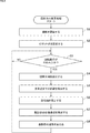
- the shooting direction change process is a process of changing the shooting direction of the subject, particularly a process of changing the shooting direction of the area of interest on the subject.
- This process starts, for example, when the power of the photographing system 11 is turned on, and ends when the power of the photographing system 11 is turned off.
- step S1 the camera 51 starts shooting. Specifically, the camera 51 starts shooting under the control of the shooting control unit 22, and starts supplying the shot image to the shooting control unit 22 and the image processing unit 24.
- step S2 the pivot point setting unit 153 sets the pivot point.
- FIG. 7 an example is shown in which the insertion portion 53 is inserted from the insertion port 202A of the patient's skin 202 and the inside of the patient's body is photographed.
- the user operates the arm unit 102 via the input unit 21 to align the tip of the insertion unit 53 with the vicinity of the center of the insertion port 202A.
- the user presses the button 201 included in the input unit 21.
- the input unit 21 supplies an input signal indicating that the button 201 has been pressed to the shooting attitude control unit 32.
- the arm posture control unit 163 detects the posture of the arm unit 102 in the global coordinate system based on the rotation angle of each actuator 171.
- the global coordinate system is a coordinate system representing the entire three-dimensional space in which the photographing system 11 exists, and is also called a world coordinate system.
- the arm posture control unit 163 supplies the arm posture data indicating the detected posture of the arm unit 102 to the pivot point setting unit 153.
- the pivot point setting unit 153 calculates the position of the tip of the insertion unit 53 in the global coordinate system based on the posture of the arm unit 102. Then, the pivot point setting unit 153 sets the calculated position of the tip of the insertion unit 53 at the pivot point P1. As a result, the pivot point P1 is set substantially at the center of the insertion port 202A.
- the pivot point setting unit 153 supplies data indicating the position of the pivot point P1 in the global coordinate system to the rotation axis setting unit 154 and the target posture setting unit 161.
- the user further inserts the insertion unit 53 into the living body by operating the arm unit 102 via the input unit 21.
- the insertion portion 53 is inserted into the living body through the insertion port 202A.
- the insertion portion 53 is inserted into the living body so that the pivot point P1 is located on the insertion portion 53. Therefore, the pivot point P1 is on the insertion portion 53 and not on the observation optical axis A1.
- step S3 the input unit 21 determines whether or not a rotation operation, that is, an operation of rotating the insertion unit 53 in order to change the shooting direction of the subject has been performed. This determination process is repeated until it is determined that the rotation operation has been performed, and when it is determined that the rotation operation has been performed, the process proceeds to step S4.
- the user specifies an angle and a direction in which the insertion unit 53 is rotated around the rotation axis via the input unit 21 as a rotation operation.
- the angle at which the insertion portion 53 is rotated may be represented by either a relative angle or an absolute angle.
- the angle and direction at which the insertion portion 53 is rotated are specified in a form such as x degrees clockwise or counterclockwise from the current position. ..
- the angle at which the insertion portion 53 is rotated is represented by an absolute angle, for example, the angle at which the insertion portion 53 is rotated is specified in a form such as a direction of x degrees with respect to a predetermined reference position.
- step S4 the observation optical axis detection unit 152 detects the observation optical axis.
- the input unit 21 supplies an input signal indicating the content of the rotation operation to the photographing control unit 22.
- the arm posture control unit 163 detects the posture of the arm unit 102 in the global coordinate system based on the rotation angle of each actuator 171.
- the arm posture control unit 163 supplies the arm posture data indicating the detected posture of the arm unit 102 to the observation optical axis detection unit 152.
- the observation optical axis detection unit 152 calculates the posture of the insertion unit 53 in the global coordinate system, particularly the posture of the observation window 54, based on the posture of the arm unit 102. Further, the observation optical axis detection unit 152 calculates the posture (position and direction) of the observation optical axis in the global coordinate system based on the posture of the observation window 54. The observation optical axis detection unit 152 supplies data indicating the attitudes of the observation window 54 and the observation optical axis to the rotation axis setting unit 154 and the target attitude setting unit 161.
- step S5 the distance detection unit 151 detects the distance to the point of interest.
- the distance detection unit 151 sets a point on the subject corresponding to the center of the captured image as a point of interest.
- the intersection P2 between the observation optical axis A1 and the surface of the subject 203 is set as the point of interest.
- the distance detection unit 151 detects the distance between the observation window 54 and the point of interest based on the left captured image and the right captured image.
- the distance detection unit 151 supplies data indicating the detection result to the rotation axis setting unit 154. For example, in the example of FIG. 8, the distance between the observation window 54 and the point of interest P2 is detected.
- Any method can be adopted as the method for detecting the distance between the observation window 54 and the point of interest.
- step S6 the rotation axis setting unit 154 sets the rotation axis. Specifically, the rotation axis setting unit 154 sets a straight line connecting the pivot point and the point of interest as the rotation axis. For example, in the example of FIG. 8, a straight line connecting the pivot point P1 and the point of interest P2 is set on the rotation axis A2.
- the rotation axis setting unit 154 supplies data indicating the attitude of the rotation axis in the global coordinate system to the target attitude setting unit 161.
- the rotation axis setting unit 154 can calculate the position of the point of interest P2 in the global coordinate system. Also, the position of the pivot point P1 in the global coordinate system is known. Therefore, the rotation axis setting unit 154 can calculate the posture of the rotation axis A2 connecting the pivot point P1 and the attention point P2.
- step S7 the target posture setting unit 161 sets the target posture of the photographing unit 23.
- the target posture setting unit 161 sets the direction and amount (rotation angle) of rotating the insertion unit 53 around the rotation axis based on the content of the rotation operation.
- the camera 51 (camera coordinate system) also rotates.
- the subject 203 may rotate significantly in the captured image before and after the rotation of the insertion portion 53, and the visibility may decrease.
- the target posture setting unit 161 has substantially the same x-axis and y-axis directions of the camera coordinate system in the global coordinate system before and after the rotation of the insertion unit 53.
- the direction and amount (rotation angle) of rotating the camera 51 around the shooting optical axis (z-axis) are calculated so as to be.
- the rotation direction of the camera 51 around the photographing optical axis is opposite to the rotation direction of the insertion portion 53 around the rotation axis A2. For example, when the rotation direction of the insertion portion 53 around the rotation axis A2 is clockwise, the rotation direction of the camera 51 around the photographing optical axis is counterclockwise.
- the target attitude setting unit 161 supplies data indicating the rotation direction and the amount of rotation of the insertion unit 53 around the rotation axis to the arm attitude control unit 163. Further, the target attitude setting unit 161 supplies data indicating the rotation direction and the amount of rotation of the camera 51 around the photographing optical axis to the camera attitude control unit 162.
- step S8 the attitude control unit 155 changes the posture of the photographing unit 23.
- the arm posture control unit 163 drives each actuator 171 to move the arm unit 102, and rotates the insertion unit 53 around the rotation axis by the rotation direction and rotation amount set by the target posture setting unit 161.
- the observation window 54 rotates on the circumference centered on the intersection of the perpendicular line drawn from the observation window 54 to the rotation axis and the rotation axis.
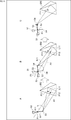
- the insertion portion 53 rotates around the rotation axis A2 and changes from the state shown in FIG. 8 to the state shown in FIG.
- the rotation axis A2 connects the pivot point P1 and the attention point P2
- the observation optical axis A1 intersects the subject 203 at the attention point P2 while the insertion portion 53 rotates around the rotation axis A2. Is maintained. Therefore, during and after the rotation of the insertion portion 53, the state in which the point corresponding to the point of interest P2 is located substantially at the center of the captured image is maintained.
- the camera attitude control unit 162 drives the rotary actuator 52 to rotate the camera 51 around the shooting optical axis by the rotation direction and the amount of rotation set by the target attitude setting unit 161.
- the camera 51 rotates around the photographing optical axis so that the rotation of the camera 51 accompanying the rotation of the insertion portion 53 is canceled according to the rotation of the insertion portion 53 around the rotation axis A2.
- the x-axis and y-axis directions of the camera coordinate system in the global coordinate system are kept substantially constant even after the insertion portion 53 is rotated. Then, it is prevented that the subject is greatly rotated around the shooting optical axis in the shot image.
- the arm attitude control unit 163 and the camera attitude control unit 162 are linked so that the x-axis and y-axis directions of the camera coordinate system in the global coordinate system are kept substantially constant even during the rotation of the insertion unit 53. , It is desirable to match the timing of rotating the insertion portion 53 and the camera 51.
- step S3 After that, the process returns to step S3, and the processes after step S3 are executed.
- the shooting direction of the subject can be easily changed. That is, in a situation where the movement of the insertion unit 53 is restricted by the pivot point (insertion port), the user can change the shooting direction of the subject without finely adjusting the movement of the insertion unit 53. Further, even if the shooting direction of the subject is changed, the movement of the point of interest in the captured image and the change in the vertical direction of the subject are suppressed. As a result, the user can easily observe the area of interest from different directions without losing sight of the area of interest on the subject.
- steps S1 to S4 the same processing as described above is performed.
- step S5 the distance detection unit 151 detects the distance to the point of interest.
- the user indicates an arbitrary point in the captured image.
- the distance detection unit 151 detects the distance between the observation window 54 and the point of interest P11 on the subject 203 corresponding to the point instructed by the user, based on the left captured image and the right captured image.
- the distance detection unit 151 supplies data indicating the detection result to the rotation axis setting unit 154.
- step S6 the rotation axis setting unit 154 sets the rotation axis.
- the rotation axis setting unit 154 is based on the position of the observation window 54 in the global coordinate system, the attitude of the observation optical axis A1, and the distance between the observation window 54 and the point of interest P11 in the global coordinate system. The position of the point of interest P11 in is calculated. Further, the rotation axis setting unit 154 is a perpendicular line drawn from the attention point P11 to the observation optical axis as shown in A of FIG. 11 based on the position of the attention point P11 and the attitude of the observation optical axis A1 in the global coordinate system. The position of the intersection P12 between L11 and the observation optical axis A1 in the global coordinate system is calculated.
- the rotation axis setting unit 154 sets the straight line connecting the pivot point P1 and the intersection point P12 on the rotation axis A11, and calculates the posture of the rotation axis A11 in the global coordinate system.
- the rotation axis setting unit 154 supplies data indicating the attitude of the rotation axis A11 in the global coordinate system to the target attitude setting unit 161.
- step S7 the target posture setting unit 161 sets the target posture of the photographing unit 23.
- the target posture setting unit 161 sets the direction and amount of rotation of the insertion unit 53 around the rotation axis A11 based on the content of the rotation operation. Further, the target posture setting unit 161 is centered on the shooting optical axis so that the x-axis and y-axis directions of the camera coordinate system in the global coordinate system are substantially the same before and after the rotation of the insertion unit 53. Calculate the direction and amount of rotation of 51.
- the target posture setting unit 161 sets the target position of the attention point P11 in the captured image after the insertion unit 53 and the camera 51 are rotated.
- the target position of the point of interest P11 may be set by the user, for example, or may be automatically set by the target posture setting unit 161.
- the target posture setting unit 161 rotates the insertion unit 53 around the pivot point P1 so that the attention point P11 moves to the target position in the captured image after the rotation of the insertion unit 53 and the camera 51. Calculate (rotation angle).
- the target attitude setting unit 161 supplies the arm attitude control unit 163 with data indicating the rotation direction and rotation amount of the insertion unit 53 around the rotation axis A11, and the rotation direction and rotation amount centered on the pivot point P1. Further, the target attitude setting unit 161 supplies data indicating the rotation direction and the amount of rotation of the insertion unit 53 around the photographing optical axis to the camera attitude control unit 162.
- step S8 the attitude control unit 155 changes the posture of the photographing unit 23.
- the arm attitude control unit 163 drives each actuator 171 to move the arm unit 102, and as shown in B of FIG. 11, the rotation direction and the amount of rotation set by the target attitude setting unit 161. Only the insertion portion 53 is rotated around the rotation axis A11.
- the camera attitude control unit 162 drives the rotary actuator 52 to rotate the camera 51 around the photographing optical axis by the rotation direction and the amount of rotation set by the target attitude setting unit 161.
- the arm posture control unit 163 drives each actuator 171 to move the arm unit 102, and inserts only the rotation direction and the rotation amount set by the target posture setting unit 161 as shown in C of FIG.
- the portion 53 is rotated around the pivot point P1.
- the observation window 54 rotates on the circumference centered on the pivot point P1.
- the point of interest P11 reaches the target position in the captured image.
- step S3 After that, the process returns to step S3, and the processes after step S3 are executed.
- the position of the point of interest P11 in the captured image is controlled by controlling the rotation of the insertion portion 53 around the rotation axis A11 and the rotation around the pivot point P1.
- the target position of the attention point P11 in the captured image is set to the same position as before the rotation, the direction in which the subject 203 is photographed is changed without moving the attention point P11 on the subject 203 in the captured image. be able to.
- the posture of is adjusted.
- the point of interest P11 on the subject 203 can be moved to the center of the captured image while changing the shooting direction of the subject 203.
- the point of interest P11 in the shot image May move to the target position.
- a in FIG. 13 shows the same state as A in FIG. 13
- the insertion portion 53 is rotated around the rotation axis A11 by a predetermined amount.
- the camera 51 is rotated around the photographing optical axis in accordance with the rotation of the insertion portion 53 around the rotation axis A11.
- the insertion portion 53 is rotated about the pivot point P1 by a predetermined amount so that the position of the attention point P11 in the captured image approaches the target position.
- the target position of the attention point P11 is set to the same position as the position before rotation, the insertion portion 53 is centered on the pivot point P1 so that the position of the attention point P11 in the captured image moves to the target position. Is rotated to.
- the point of interest P11 is set to the target position in the captured image almost at the same time as the rotation of the insertion portion 53 around the rotation axis A11 is completed. Moving.
- the attention point P11 when the target position of the attention point P11 is the same as the position before the rotation, the attention point P11 is fixed at substantially the same position in the captured image during and after the rotation of the insertion portion 53.
- the target position of the attention point P11 when the target position of the attention point P11 is different from the position before rotation, the attention point P11 is gradually brought closer to the target position in the captured image. Therefore, for example, it is possible to prevent the user from losing sight of the area of interest around the point of interest P11.
- the user can easily change the shooting direction of the subject, set an arbitrary point on the subject as the attention point, and move the attention point to an arbitrary target position in the captured image. ..
- a marker 301 is provided around the insertion port 202A of the patient's skin 202, and the camera 51 photographs the periphery of the marker 301 before inserting the insertion portion 53.
- the marker 301 is realized by any method such as sticking, printing, and irradiation of pattern light. Then, the distance between the observation window 54 and the center of the insertion port 202A in the marker 301 is detected based on the left captured image and the right captured image. Further, the position of the observation window 54 in the global coordinate system is detected based on the posture of the arm portion 102.
- the position of the center of the insertion port 202A in the global coordinate system is detected based on the position of the observation window 54 in the global coordinate system and the distance between the observation window 54 and the center of the insertion port 202A in the marker 301. To. Then, the position of the center of the insertion port 202A in the global coordinate system is set as the pivot point.
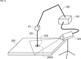
- an insertion unit 321 is provided instead of the insertion unit 53 of the photographing unit 23.
- An observation window 322 is provided on the tip surface of the insertion portion 321 as in the insertion portion 53.
- a marker (not shown) having a predetermined pattern is provided at the tip of the insertion portion 321.
- the camera 323 photographs the surroundings of the insertion port 202A, and supplies the obtained captured image to the pivot point setting unit 153 in the base unit 101.
- the pivot point setting unit 153 receives the image taken from the camera 323 with the tip of the insertion portion 321 entering the insertion port 202A and the tip of the insertion portion 321. Detects the moment when the marker disappears.
- the pivot point setting unit 153 calculates the position of the tip of the insertion unit 321 in the global coordinate system based on the posture of the arm unit 102 at the time of shooting the captured image at the moment when the marker at the tip of the insertion unit 321 disappears. Then, the pivot point setting unit 153 sets the calculated position of the tip of the insertion unit 321 as the pivot point.
- a light emitting element may be provided at the tip of the insertion unit 321 instead of the marker, and the pivot point setting unit 153 may detect the moment when the light emitting element disappears in the captured image from the camera 51.
- the pivot point setting process may be omitted.
- the pivot point setting process may be performed every time the rotation operation is performed.
- the angle of the observation optical axis A1 with respect to the normal vector at the point P22 of the subject 353 becomes large. That is, the image is taken from the direction in which the periphery of the point P22 is greatly inclined from the front. Therefore, the visibility around the point P22 in the captured image may decrease.
- the observation window 54 (observation optical axis) is directed in the direction in which the observation window 54 (insertion portion 53) rotates, and then the insertion portion 53 is inserted. It may be rotated.
- the direction of the observation window 54 (the direction of the observation optical axis A1) is in the rotation direction around the pivot point P1 of the observation window 54 (insertion portion 53).
- the insertion portion 53 is rotated about the rotation axis A21 connecting the pivot point P1 and the point P21 so as to approach each other.
- the insertion portion 53 is rotated around the pivot point P1 so that the observation optical axis A1 intersects the point P22 on the subject 353.
- the insertion portion 53', the observation window 54', and the observation optical axis A1'of C in FIG. 16 are when the insertion portion 53 is rotated around the pivot point P1 without being rotated around the rotation axis A21.
- the positions of the insertion portion 53, the observation window 54, and the observation optical axis A1 are shown.
- the observation optical axis A1 has a smaller angle with respect to the normal vector at the point P22 of the subject 353 as compared with the observation optical axis A1'. That is, by rotating the insertion portion 53 around the rotation axis A21, the vicinity of the point P22 can be photographed from a direction closer to the front surface, and the visibility is improved.
- the process of directing the observation window 54 (observation optical axis A1) in the rotation direction of the observation window 54 may be automatically performed or may be performed by a user operation.
- the stick 351A of the stick controller 351 provided in the input unit 21 is tilted by a predetermined angle or more, or when it is continuously tilted in the same direction for a predetermined time or longer, it is observed in the rotation direction of the observation window 54.
- the process of pointing the window 54 may be performed.
- the function of pointing the observation window 54 in the rotation direction of the observation window 54 may be switched on / off.
- the rotation of the insertion portion 53 around the pivot point P1 and the rotation around the rotation axis A21 may be repeated little by little alternately.
- a laser an ultrasonic sensor, an infrared sensor, a depth sensor, or the like may be used to detect the distance to the point of interest.
- the distance to each point around the point of interest may be detected according to the degree of unevenness on the surface of the subject, and the average value of the detected distances may be used as the distance to the point of interest.
- the detection process of the distance to the point of interest may be omitted. This is assumed, for example, when the three-dimensional shape inside the patient's body is known by CT (Computed Tomography) scan or the like.
- markers may be provided in each part of the arm part 102, the position of each marker may be detected by a motion capture system or the like, and the posture of the arm part 102 may be detected based on the position of each marker.
- the arm portion is not limited to the above-mentioned configuration, and can be arbitrarily changed. For example, it is possible to increase the number of joints and change the direction and angle of bending the joints.
- insertion portion configured by a rigid mirror
- present technology can also be applied to, for example, a case where the insertion portion is configured by a flexible mirror such as a fiberscope.
- This technology is applied not only to the above-mentioned case of photographing the inside of a living body, but also to the case of rotating a rod-shaped optical member whose observation optical axis is tilted with respect to the central axis with the pivot point as a fulcrum. be able to.
- FIG. 17 is a block diagram showing a configuration example of the hardware of the computer 1000 that executes the above-mentioned series of processes programmatically.
- the CPU Central Processing Unit
- ROM Read Only Memory
- RAM Random Access Memory
- An input / output interface 1005 is further connected to the bus 1004.
- An input unit 1006, an output unit 1007, a storage unit 1008, a communication unit 1009, and a drive 1010 are connected to the input / output interface 1005.
- the input unit 1006 includes a keyboard, a mouse, a microphone, and the like.
- the output unit 1007 includes a display, a speaker, and the like.
- the storage unit 1008 includes a hard disk, a non-volatile memory, and the like.
- the communication unit 1009 includes a network interface and the like.
- the drive 1010 drives a removable medium 1011 such as a magnetic disk, an optical disk, a magneto-optical disk, or a semiconductor memory.
- the CPU 1001 loads and executes the program stored in the storage unit 1008 into the RAM 1003 via the input / output interface 1005 and the bus 1004, for example. A series of processing is performed.
- the program executed by the computer 1000 can be recorded and provided on the removable media 1011 as a package media or the like, for example. Programs can also be provided via wired or wireless transmission media such as local area networks, the Internet, and digital satellite broadcasting.
- the program can be installed in the storage unit 1008 via the input / output interface 1005 by mounting the removable media 1011 in the drive 1010.
- the program can be received by the communication unit 1009 and installed in the storage unit 1008 via a wired or wireless transmission medium.
- the program can be pre-installed in the ROM 1002 or the storage unit 1008.
- the program executed by the computer 1000 may be a program in which processing is performed in chronological order in the order described in this specification, or at a required timing such as in parallel or when a call is made. It may be a program that is processed by.
- the system means a set of a plurality of components (devices, modules (parts), etc.), and it does not matter whether all the components are in the same housing. Therefore, a plurality of devices housed in separate housings and connected via a network, and a device in which a plurality of modules are housed in one housing are both systems. ..
- this technology can have a cloud computing configuration in which one function is shared by a plurality of devices via a network and processed jointly.
- each step described in the above flowchart can be executed by one device or can be shared and executed by a plurality of devices.
- one step includes a plurality of processes
- the plurality of processes included in the one step can be executed by one device or shared by a plurality of devices.
- the present technology can also have the following configurations.
- a rotation axis setting unit that serves as a fulcrum of a rod-shaped optical member whose observation optical axis is tilted with respect to the central axis, and sets a rotation axis based on a pivot point that is not on the observation optical axis and a point of interest on the subject.
- An imaging control device including an attitude control unit that rotates the optical member around the rotation axis.
- An imaging device that photographs the subject via the optical member is rotatably connected to the optical member about the optical axis of the imaging device.
- the attitude control unit moves in a second direction opposite to the first direction around the optical axis of the photographing apparatus in accordance with the rotation of the optical member in the first direction about the rotation axis.
- the imaging control device which rotates the imaging device.
- the attitude control unit controls the rotation of the optical member around the rotation axis and the rotation of the optical member around the pivot point, and photographs the subject through the optical member.
- the imaging control device according to (1) or (2), which controls the position of the point of interest in an image.
- the attitude control unit controls the rotation of the optical member around the pivot point so that the point of interest in the captured image after the rotation of the optical member about the rotation axis reaches a target position.
- the imaging control device according to (5) above.
- the attitude control unit rotates the optical member about the rotation axis by a predetermined amount of rotation, and the optics centering on the rotation axis until the point of interest in the captured image reaches the target position.
- the imaging control device according to (6) or (7) above, wherein the rotation of the member and the rotation of the optical member about the pivot point are alternately repeated.
- the imaging control device according to any one of (5) to (8) above, wherein the point of interest is a point on the subject corresponding to the designated point in the captured image.
- the rotation axis setting unit sets a straight line connecting the intersection of the perpendicular line drawn from the attention point to the observation optical axis and the observation optical axis and the pivot point on the rotation axis (5) to (9). ).
- the imaging control device according to any one of.
- the optical member is inserted into the living body and The imaging control device according to any one of (1) to (10) above, wherein the pivot point is a point on the optical member near the insertion port for inserting the optical member into the living body.
- the attitude control unit rotates the optical member in the first direction around the pivot point
- the attitude control unit rotates the optical member in the second direction around the rotation axis and directs the observation optical axis.
- the imaging control device according to any one of (1) to (13), wherein the image is brought closer to the first direction.
- the posture control unit controls the rotation of the optical member by controlling the posture of the arm unit that moves the optical member.
- a rotation axis is set based on a pivot point that is not on the observation optical axis and a point of interest on the subject, which serves as a fulcrum of a rod-shaped optical member whose observation optical axis is tilted with respect to the central axis.
- a rotation axis is set based on a pivot point that is not on the observation optical axis and a point of interest on the subject, which serves as a fulcrum of a rod-shaped optical member whose observation optical axis is tilted with respect to the central axis.
- An imaging unit equipped with a rod-shaped optical member whose observation optical axis is tilted with respect to the central axis, A rotation axis setting unit that serves as a fulcrum of the optical member and sets a rotation axis based on a pivot point that is not on the observation optical axis and a point of interest on the subject.
- An imaging system including an attitude control unit that rotates the optical member around the rotation axis.
- 11 shooting system 22 shooting control unit, 23 shooting unit, 26 arm mechanism, 51 camera, 52 rotary actuator, 53 insertion part, 54a, 54b observation window, 102 arm part, 112-1 to 112-4 joint part, 151 distance Detection unit, 152 Observation optical axis detection unit, 153 Pivot point setting unit, 154 Rotation axis setting unit, 155 Attitude control unit, 161 Target attitude setting unit, 162 Camera attitude control unit, 163 Arm attitude control unit, 171-1 to 171 -N actuator
Landscapes
- Health & Medical Sciences (AREA)
- Life Sciences & Earth Sciences (AREA)
- Surgery (AREA)
- Engineering & Computer Science (AREA)
- Nuclear Medicine, Radiotherapy & Molecular Imaging (AREA)
- Veterinary Medicine (AREA)
- Public Health (AREA)
- General Health & Medical Sciences (AREA)
- Physics & Mathematics (AREA)
- Animal Behavior & Ethology (AREA)
- Molecular Biology (AREA)
- Biomedical Technology (AREA)
- Heart & Thoracic Surgery (AREA)
- Medical Informatics (AREA)
- Pathology (AREA)
- Radiology & Medical Imaging (AREA)
- Optics & Photonics (AREA)
- Biophysics (AREA)
- General Physics & Mathematics (AREA)
- Signal Processing (AREA)
- Robotics (AREA)
- Oral & Maxillofacial Surgery (AREA)
- Gynecology & Obstetrics (AREA)
- Endoscopes (AREA)
- Instruments For Viewing The Inside Of Hollow Bodies (AREA)
- Accessories Of Cameras (AREA)
- Details Of Cameras Including Film Mechanisms (AREA)
- Stereoscopic And Panoramic Photography (AREA)
Abstract
L'invention concerne : un dispositif de commande d'imagerie qui, pendant la capture d'images à l'aide d'un élément optique ayant un axe optique d'observation incliné par rapport à l'axe central, permet de modifier facilement la direction de capture d'images d'un sujet ; un procédé de commande d'imagerie ; un programme ; et un système d'imagerie. Le dispositif de commande d'imagerie selon l'invention est pourvu d'une unité de réglage d'axe de rotation, qui sert de point d'appui pour un élément optique de type tige ayant un axe optique d'observation incliné par rapport à l'axe central et règle l'axe de rotation sur la base d'un point de pivotement qui ne se trouve pas sur l'axe optique d'observation et d'un point d'intérêt sur le sujet, et d'une unité de commande d'orientation servant à faire tourner l'élément optique autour de l'axe de rotation. La présente invention peut être appliquée, par exemple, aux systèmes d'endoscope.
Priority Applications (2)
| Application Number | Priority Date | Filing Date | Title |
|---|---|---|---|
| EP20777446.4A EP3949828B1 (fr) | 2019-03-28 | 2020-03-16 | Dispositif de commande d'imagerie, procédé de commande d'imagerie, programme et système d'imagerie |
| US17/430,226 US12245747B2 (en) | 2019-03-28 | 2020-03-16 | Imaging control device, imaging control method, program, and imaging system |
Applications Claiming Priority (2)
| Application Number | Priority Date | Filing Date | Title |
|---|---|---|---|
| JP2019063439A JP2020162633A (ja) | 2019-03-28 | 2019-03-28 | 撮影制御装置、撮影制御方法、プログラム、及び、撮影システム |
| JP2019-063439 | 2019-03-28 |
Publications (1)
| Publication Number | Publication Date |
|---|---|
| WO2020196026A1 true WO2020196026A1 (fr) | 2020-10-01 |
Family
ID=72611491
Family Applications (1)
| Application Number | Title | Priority Date | Filing Date |
|---|---|---|---|
| PCT/JP2020/011447 Ceased WO2020196026A1 (fr) | 2019-03-28 | 2020-03-16 | Dispositif de commande d'imagerie, procédé de commande d'imagerie, programme et système d'imagerie |
Country Status (4)
| Country | Link |
|---|---|
| US (1) | US12245747B2 (fr) |
| EP (1) | EP3949828B1 (fr) |
| JP (1) | JP2020162633A (fr) |
| WO (1) | WO2020196026A1 (fr) |
Families Citing this family (1)
| Publication number | Priority date | Publication date | Assignee | Title |
|---|---|---|---|---|
| DE112021008246T5 (de) | 2021-11-30 | 2024-07-04 | Olympus Corporation | Endoskopsystem und koordinatensystemkorrekturverfahren |
Citations (3)
| Publication number | Priority date | Publication date | Assignee | Title |
|---|---|---|---|---|
| JP2001149301A (ja) * | 1999-11-29 | 2001-06-05 | Olympus Optical Co Ltd | 硬性鏡システム |
| WO2015083459A1 (fr) * | 2013-12-05 | 2015-06-11 | オリンパス株式会社 | Système d'endoscope stéréoscopique |
| JP2018075218A (ja) * | 2016-11-10 | 2018-05-17 | ソニー株式会社 | 医療用支持アーム及び医療用システム |
Family Cites Families (16)
| Publication number | Priority date | Publication date | Assignee | Title |
|---|---|---|---|---|
| US5876325A (en) * | 1993-11-02 | 1999-03-02 | Olympus Optical Co., Ltd. | Surgical manipulation system |
| JP2003088532A (ja) | 2001-09-19 | 2003-03-25 | Olympus Optical Co Ltd | 手術装置 |
| US20200337534A1 (en) * | 2011-12-03 | 2020-10-29 | Koninklijke Philips N.V. | Surgical port localization |
| JP6715823B2 (ja) * | 2014-07-15 | 2020-07-01 | コーニンクレッカ フィリップス エヌ ヴェKoninklijke Philips N.V. | X線スイートにおける画像統合及びロボット内視鏡制御 |
| JP6519144B2 (ja) * | 2014-11-06 | 2019-05-29 | ソニー株式会社 | 内視鏡システム、画像処理装置、画像処理方法、およびプログラム |
| EP3359075B1 (fr) * | 2015-10-09 | 2021-08-18 | Covidien LP | Appareil comprenant un endoscope coudé et des moyens pour faire tourner l'endoscope et pour générer une vue panoramique |
| WO2017091704A1 (fr) * | 2015-11-25 | 2017-06-01 | Camplex, Inc. | Systèmes et affichages de visualisation chirurgicale |
| DE102016105907A1 (de) * | 2016-03-31 | 2017-10-05 | Tuebingen Scientific Medical Gmbh | Chirurgisches Roboter-Instrumenten-System |
| EP3435906B1 (fr) * | 2016-03-31 | 2024-05-08 | Koninklijke Philips N.V. | Système robotique guidé par image d'aspiration de tumeur |
| EP3590406A4 (fr) | 2017-02-28 | 2020-04-01 | Sony Corporation | Système d'observation médicale, dispositif de commande et procédé de commande |
| WO2018217951A1 (fr) * | 2017-05-24 | 2018-11-29 | Camplex, Inc. | Systèmes de visualisation chirurgicale et dispositifs d'affichage |
| JP7115493B2 (ja) * | 2017-11-01 | 2022-08-09 | ソニーグループ株式会社 | 手術アームシステム及び手術アーム制御システム |
| CA3089681A1 (fr) * | 2018-02-07 | 2019-08-15 | Distalmotion Sa | Systemes robotiques chirurgicaux comportant des telemanipulateurs robotises et une laparoscopie integree |
| US12376927B2 (en) * | 2018-02-07 | 2025-08-05 | Distalmotion Sa | Surgical robot systems comprising robotic telemanipulators and integrated laparoscopy |
| DE102018103968A1 (de) * | 2018-02-22 | 2019-08-22 | Karl Storz Se & Co. Kg | Vorrichtung zur simultanen Fixierung von medizinischen Instrumenten und entsprechendes System |
| CN115802978A (zh) * | 2020-07-09 | 2023-03-14 | 索尼集团公司 | 医疗臂装置 |
-
2019
- 2019-03-28 JP JP2019063439A patent/JP2020162633A/ja active Pending
-
2020
- 2020-03-16 US US17/430,226 patent/US12245747B2/en active Active
- 2020-03-16 EP EP20777446.4A patent/EP3949828B1/fr active Active
- 2020-03-16 WO PCT/JP2020/011447 patent/WO2020196026A1/fr not_active Ceased
Patent Citations (3)
| Publication number | Priority date | Publication date | Assignee | Title |
|---|---|---|---|---|
| JP2001149301A (ja) * | 1999-11-29 | 2001-06-05 | Olympus Optical Co Ltd | 硬性鏡システム |
| WO2015083459A1 (fr) * | 2013-12-05 | 2015-06-11 | オリンパス株式会社 | Système d'endoscope stéréoscopique |
| JP2018075218A (ja) * | 2016-11-10 | 2018-05-17 | ソニー株式会社 | 医療用支持アーム及び医療用システム |
Non-Patent Citations (1)
| Title |
|---|
| See also references of EP3949828A4 * |
Also Published As
| Publication number | Publication date |
|---|---|
| EP3949828B1 (fr) | 2024-10-09 |
| US20220160214A1 (en) | 2022-05-26 |
| EP3949828A1 (fr) | 2022-02-09 |
| US12245747B2 (en) | 2025-03-11 |
| EP3949828A4 (fr) | 2022-05-18 |
| JP2020162633A (ja) | 2020-10-08 |
Similar Documents
| Publication | Publication Date | Title |
|---|---|---|
| JP7248554B2 (ja) | イメージング器具の向きの制御のためのシステム及び方法 | |
| EP2822445B1 (fr) | Système de commande endoscopique global | |
| JP7081584B2 (ja) | 医療用観察システム、制御装置及び制御方法 | |
| JP5737796B2 (ja) | 内視鏡操作システムおよび内視鏡操作プログラム | |
| KR102117273B1 (ko) | 수술 로봇 시스템 및 그 제어 방법 | |
| JP5814938B2 (ja) | リアルタイム速度最適化を使用した校正不要のビジュアルサーボ | |
| JP2023549687A (ja) | 関節の内部自由度を備えた腹腔鏡手術ロボットシステム | |
| US20200204741A1 (en) | Camera array for a mediated-reality system | |
| CN108601626A (zh) | 基于图像的机器人引导 | |
| JP2013516264A5 (fr) | ||
| US20230139425A1 (en) | Systems and methods for optimizing configurations of a computer-assisted surgical system for reachability of target objects | |
| EP3530228B1 (fr) | Dispositif de microscope et procédé de commande | |
| US12419698B2 (en) | System and method of displaying images from imaging devices | |
| US20240269856A1 (en) | Robot device for guiding a robotic arm | |
| WO2020196026A1 (fr) | Dispositif de commande d'imagerie, procédé de commande d'imagerie, programme et système d'imagerie | |
| WO2018025484A1 (fr) | Système de prise de vues photographiques, procédé de prise de vues photographiques et appareil de commande | |
| JP7854499B2 (ja) | 内視鏡システム、内視鏡システムの作動方法および手技支援プログラム | |
| KR102875760B1 (ko) | 하부 위장관 이미지 획득을 위한 내시경 장치 및 제어 방법 | |
| KR102875761B1 (ko) | 상부 위장관 이미지 획득을 위한 내시경 장치 및 제어 방법 | |
| JP2008017347A (ja) | 映像表示装置、映像信号の歪み補正処理方法 |
Legal Events
| Date | Code | Title | Description |
|---|---|---|---|
| 121 | Ep: the epo has been informed by wipo that ep was designated in this application |
Ref document number: 20777446 Country of ref document: EP Kind code of ref document: A1 |
|
| NENP | Non-entry into the national phase |
Ref country code: DE |
|
| ENP | Entry into the national phase |
Ref document number: 2020777446 Country of ref document: EP Effective date: 20211028 |
|
| WWG | Wipo information: grant in national office |
Ref document number: 17430226 Country of ref document: US |