WO2020196201A1 - Procédé de commande de communication - Google Patents
Procédé de commande de communication Download PDFInfo
- Publication number
- WO2020196201A1 WO2020196201A1 PCT/JP2020/012148 JP2020012148W WO2020196201A1 WO 2020196201 A1 WO2020196201 A1 WO 2020196201A1 JP 2020012148 W JP2020012148 W JP 2020012148W WO 2020196201 A1 WO2020196201 A1 WO 2020196201A1
- Authority
- WO
- WIPO (PCT)
- Prior art keywords
- iab node
- rlf
- function unit
- gnb
- notification
- Prior art date
- Legal status (The legal status is an assumption and is not a legal conclusion. Google has not performed a legal analysis and makes no representation as to the accuracy of the status listed.)
- Ceased
Links
Images








Classifications
-
- H—ELECTRICITY
- H04—ELECTRIC COMMUNICATION TECHNIQUE
- H04W—WIRELESS COMMUNICATION NETWORKS
- H04W36/00—Hand-off or reselection arrangements
- H04W36/24—Reselection being triggered by specific parameters
- H04W36/30—Reselection being triggered by specific parameters by measured or perceived connection quality data
- H04W36/305—Handover due to radio link failure
-
- H—ELECTRICITY
- H04—ELECTRIC COMMUNICATION TECHNIQUE
- H04W—WIRELESS COMMUNICATION NETWORKS
- H04W16/00—Network planning, e.g. coverage or traffic planning tools; Network deployment, e.g. resource partitioning or cells structures
- H04W16/24—Cell structures
- H04W16/26—Cell enhancers or enhancement, e.g. for tunnels, building shadow
-
- H—ELECTRICITY
- H04—ELECTRIC COMMUNICATION TECHNIQUE
- H04W—WIRELESS COMMUNICATION NETWORKS
- H04W36/00—Hand-off or reselection arrangements
- H04W36/34—Reselection control
- H04W36/36—Reselection control by user or terminal equipment
- H04W36/362—Conditional handover
-
- H—ELECTRICITY
- H04—ELECTRIC COMMUNICATION TECHNIQUE
- H04W—WIRELESS COMMUNICATION NETWORKS
- H04W40/00—Communication routing or communication path finding
- H04W40/24—Connectivity information management, e.g. connectivity discovery or connectivity update
-
- H—ELECTRICITY
- H04—ELECTRIC COMMUNICATION TECHNIQUE
- H04W—WIRELESS COMMUNICATION NETWORKS
- H04W84/00—Network topologies
- H04W84/02—Hierarchically pre-organised networks, e.g. paging networks, cellular networks, WLAN [Wireless Local Area Network] or WLL [Wireless Local Loop]
- H04W84/04—Large scale networks; Deep hierarchical networks
- H04W84/042—Public Land Mobile systems, e.g. cellular systems
- H04W84/047—Public Land Mobile systems, e.g. cellular systems using dedicated repeater stations
Definitions
- the present disclosure relates to a communication control method used in a mobile communication system.
- a new relay device called an IAB (Integrated Access and Backhaul) node is being studied.
- One or more relay devices intervene in the communication between the base station and the user equipment, and relay the communication.
- Such a relay device has a user device function and a base station function, and uses the user device function to perform wireless communication with a higher-level node (base station or higher-level relay device) and uses the base station function to perform lower-level communication. Performs wireless communication with a node (user device or lower relay device).
- the wireless section between the user device and the relay device or base station is sometimes called an access link.
- the radio section between the relay device and the base station or other relay device is sometimes referred to as a backhaul link.
- the data transfer path is operated by integrating and multiplexing access link data communication and backhaul link data communication at layer 2 and dynamically allocating radio resources to the backhaul link. The method of switching is described.
- the communication control method is a method using a relay device that wirelessly relays communication between a higher-level device and a lower-level device.
- the communication control method includes that, in the relay device, a user device function unit wirelessly connected to the higher-level device notifies a base station function unit wirelessly connected to the lower-level device of state information.
- the state information is information indicating at least one of the RRC state of the user device function unit and the wireless link state between the higher-level device and the user device function unit.
- the communication control method is a method using a relay device that wirelessly relays communication between a higher-level device and a lower-level device.
- a base station function unit wirelessly connected to the lower device communicates with a donor device via a user device function unit wirelessly connected to the host device or the host device.
- the state information is information indicating a wireless link state between the base station functional unit and the lower device.
- the communication control method is a method using a relay device that wirelessly relays communication between a higher-level device and a lower-level device.
- the relay device receives a notification indicating the occurrence of a wireless link failure with another relay device from a lower device connected to the relay device, and the relay device notifies the donor device. It includes transmitting a message regarding the wireless link failure.
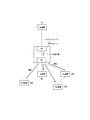
- FIG. 1 is a diagram showing a configuration of a mobile communication system 1 according to the present embodiment.
- the mobile communication system 1 is a fifth generation (5G) mobile communication system based on the 3GPP standard.
- the wireless access system in the mobile communication system 1 is NR (New Radio), which is a 5G wireless access system.
- NR New Radio
- LTE Long Term Evolution
- the mobile communication system 1 includes a 5G core network (5GC) 10, a user device (UE) 100, a base station (referred to as gNB) 200, and an IAB node 300.
- 5GC 5G core network
- UE user device
- gNB base station
- IAB node 300 IAB node 300.
- the base station may be an LTE base station (that is, eNB).
- the 5GC10 includes an AMF (Access and Mobility Management Function) 11 and an UPF (User Plane Function) 12.
- the AMF 11 is a device that performs various mobility controls and the like for the UE 100.
- the AMF 11 manages information on the area in which the UE 100 resides by communicating with the UE 100 using NAS (Non-Access Stratum) signaling.
- the UPF 12 is a device that controls the transfer of user data and the like.
- the gNB 200 is connected to the 5GC10 via an interface called an NG interface. In FIG. 1, three gNB200-1 to gNB200-3 connected to 5GC10 are illustrated.
- the gNB 200 is a fixed wireless communication device that performs wireless communication with the UE 100. When the gNB 200 has a donor function, the gNB 200 may perform wireless communication with an IAB node that wirelessly connects to itself.
- the gNB 200 is connected to another gNB 200 that is adjacent to the gNB 200 via an inter-base station interface called an Xn interface.
- FIG. 1 shows an example in which gNB200-1 is connected to gNB200-2 and gNB200-2.
- Each gNB 200 manages one or more cells.
- Cell is used as a term to indicate the smallest unit of wireless communication area.
- the cell may be used as a term indicating a function or resource for wireless communication with the UE 100.
- One cell belongs to one carrier frequency.
- the UE 100 is a mobile wireless communication device that performs wireless communication with the gNB 200.
- the UE 100 may perform wireless communication with the IAB node 300.
- the UE 100 may be any device that performs wireless communication with the gNB 200 or the IAB node 300.
- the UE 100 is a mobile phone terminal, a tablet terminal, a notebook PC, a sensor or a device provided in the sensor, or a vehicle or a device provided in the vehicle.
- FIG. 1 shows an example in which UE 100-1 is wirelessly connected to gNB200-1, UE100-2 is wirelessly connected to IAB node 300-1, and UE100-3 is wirelessly connected to IAB node 300-2. ing.
- the UE 100-1 directly communicates with the gNB 200-1.
- the UE 100-2 indirectly communicates with the gNB 200-1 via the IAB node 300-1.
- the UE 100-3 indirectly communicates with the gNB 200-1 via the IAB node 300-1 and the IAB node 300-2.
- the IAB node 300 is a device (relay device) that intervenes in the communication between the eNB 200 and the UE 100 and relays the communication.
- FIG. 1 shows an example in which the IAB node 300-1 is wirelessly connected to the donor gNB200-1 and the IAB node 300-2 is wirelessly connected to the IAB node 300-1.
- Each IAB node 300 manages a cell.
- the cell ID of the cell managed by the IAB node 300 may be the same as or different from the cell ID of the cell of the donor gNB200-1.
- the IAB node 300 has a UE function (user equipment function) and a gNB function (base station function).
- the IAB node 300 uses the UE function to perform wireless communication with the upper node (gNB 200 or the upper IAB node 300), and also uses the gNB function to perform wireless communication with the lower node (UE 100 or the lower IAB node 300).
- the UE function means at least a part of the functions of the UE 100, and the IAB node 300 does not necessarily have all the functions of the UE 100.
- the gNB function means at least a part of the functions of the gNB 200, and the IAB node 300 does not necessarily have all the functions of the gNB 200.
- the radio section between the UE 100 and the IAB node 300 or gNB 200 may be referred to as an access link (or Uu).
- the radio section between the IAB node 300 and the gNB 200 or other IAB node 300 may be referred to as a backhaul link (or Un).
- a backhaul link may be referred to as a fronthaul link.
- a millimeter wave band may be used for the access link and the backhaul link.
- the access link and the backhaul link may be multiplexed by time division and / or frequency division.
- FIG. 2 is a diagram showing the configuration of gNB 200.
- the gNB 200 includes a wireless communication unit 210, a network communication unit 220, and a control unit 230.
- the wireless communication unit 210 is used for wireless communication with the UE 100 and wireless communication with the IAB node 300.
- the wireless communication unit 210 includes a receiving unit 211 and a transmitting unit 212.
- the receiving unit 211 performs various receptions under the control of the control unit 230.
- the receiving unit 211 includes an antenna, converts the radio signal received by the antenna into a baseband signal (received signal), and outputs the radio signal to the control unit 230.
- the transmission unit 212 performs various transmissions under the control of the control unit 230.
- the transmission unit 212 includes an antenna, converts a baseband signal (transmission signal) output by the control unit 230 into a radio signal, and transmits the baseband signal (transmission signal) from the antenna.
- the network communication unit 220 is used for wired communication (or wireless communication) with 5GC10 and wired communication (or wireless communication) with another adjacent gNB200.
- the network communication unit 220 includes a reception unit 221 and a transmission unit 222.
- the receiving unit 221 performs various types of reception under the control of the control unit 230.
- the receiving unit 221 receives a signal from the outside and outputs the received signal to the control unit 230.
- the transmission unit 222 performs various transmissions under the control of the control unit 230.
- the transmission unit 222 transmits the transmission signal output by the control unit 230 to the outside.
- the control unit 230 performs various controls on the gNB 200.
- the control unit 230 includes at least one processor and at least one memory.
- the memory stores a program executed by the processor and information used for processing by the processor.
- the processor may include a baseband processor and a CPU (Central Processing Unit).
- the baseband processor modulates / demodulates and encodes / decodes the baseband signal.
- the CPU executes a program stored in the memory to perform various processes.
- the processor executes a process described later.
- FIG. 3 is a diagram showing the configuration of the IAB node 300.
- the IAB node 300 includes a wireless communication unit 310 and a control unit 320.
- the wireless communication unit 310 is used for wireless communication with the gNB 200 (backhaul link) and wireless communication with the UE 100 (access link).
- the wireless communication unit 310 includes a receiving unit 311 and a transmitting unit 312.
- the receiving unit 311 performs various types of reception under the control of the control unit 320.
- the receiving unit 311 includes an antenna, converts the radio signal received by the antenna into a baseband signal (received signal), and outputs the radio signal to the control unit 320.
- the transmission unit 312 performs various transmissions under the control of the control unit 320.
- the transmission unit 312 includes an antenna, converts the baseband signal (transmission signal) output by the control unit 320 into a radio signal, and transmits the baseband signal (transmission signal) from the antenna.
- the control unit 320 performs various controls on the IAB node 300.
- the control unit 320 includes at least one processor and at least one memory.
- the memory stores a program executed by the processor and information used for processing by the processor.
- the processor may include a baseband processor and a CPU.
- the baseband processor modulates / demodulates and encodes / decodes the baseband signal.
- the CPU executes a program stored in the memory to perform various processes.
- the processor executes a process described later.
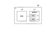
- FIG. 4 is a diagram showing the configuration of the UE 100. As shown in FIG. 4, the UE 100 includes a wireless communication unit 110 and a control unit 120.
- the wireless communication unit 110 is used for wireless communication on the access link, that is, wireless communication with the gNB 200 and wireless communication with the IAB node 300.
- the wireless communication unit 110 includes a receiving unit 111 and a transmitting unit 112.
- the receiving unit 111 performs various types of reception under the control of the control unit 120.
- the receiving unit 111 includes an antenna, converts the radio signal received by the antenna into a baseband signal (received signal), and outputs the radio signal to the control unit 120.
- the transmission unit 112 performs various transmissions under the control of the control unit 120.
- the transmission unit 112 includes an antenna, converts a baseband signal (transmission signal) output by the control unit 120 into a radio signal, and transmits the baseband signal (transmission signal) from the antenna.
- the control unit 120 performs various controls on the UE 100.
- the control unit 120 includes at least one processor and at least one memory.
- the memory stores a program executed by the processor and information used for processing by the processor.
- the processor may include a baseband processor and a CPU.
- the baseband processor modulates / demodulates and encodes / decodes the baseband signal.
- the CPU executes a program stored in the memory to perform various processes.
- the processor executes a process described later.
- FIG. 5 is a diagram showing an example of a protocol stack configuration of the user plane.
- a protocol stack configuration relating to user data transmission between the UE 100-3 shown in FIG. 1 and the UPF 12 of the 5GC10 will be described.
- UPF12 includes GTP-U (GPRS Tunneling Protocol for User Plane), UDP (User Datagram Protocol), IP (Internet Protocol), and Layer 1 / Layer 2 (L1 / L2). Be prepared.
- the gNB200-1 (donor gNB) is provided with a protocol stack corresponding to these.
- the gNB 200-1 includes an aggregation unit (CU: Central Unit) and a distribution unit (DU: Distributed Unit).
- the CU has each layer of PDCP (Packet Data Convergence Protocol) or higher in the protocol stack of the wireless interface, and the DU has each layer below RLC (Radio Link Control).
- PDCP Packet Data Convergence Protocol
- RLC Radio Link Control
- the CU includes SDAP (Service Data Adaptation Protocol), PDCP, IP, and L1 / L2.
- SDAP Service Data Adaptation Protocol
- PDCP Packet Control Protocol
- IP Packet Control Protocol
- L1 / L2 Low-power Packet Control Protocol
- the SDAP and PDCP of the CU communicate with the SDAP and PDCP of the UE 100 via the DU, the IAB node 300-1 and the IAB node 300-2.
- the DU has an RLC, an adaptation layer (Adapt), a MAC (Medium Access Control), and a PHY (Physical layer) in the protocol stack of the wireless interface.
- RLC Radio Link Control
- Adapt adaptation layer
- MAC Medium Access Control
- PHY Physical layer
- the IAB node 300-1 is provided with the protocol stack ST1 for the UE corresponding to these. Further, the IAB node 300-1 is provided with the protocol stack ST2 for gNB. Both the protocol stack ST1 and the protocol stack ST2 are composed of layers (each sublayer) below layer 2. That is, the IAB node 300-1 is a layer 2 relay device that relays user data using each layer of layer 2 or lower. The IAB node 300-1 relays data without using a layer of layer 3 or higher (specifically, a layer of PDCP or higher).
- the IAB node 300-2 has a protocol stack configuration similar to that of the IAB node 300-1.
- each of the gNB 200-1, the IAB node 300-1, the IAB node 300-2, and the UE 100-3 is provided with an RRC (Radio Resource Control) corresponding to layer 3.
- RRC Radio Resource Control
- An RRC connection is established between the RRC of gNB200-1 (donor gNB) and the RRC of IAB node 300-1, and RRC messages are transmitted and received using this RRC connection. Further, an RRC connection is established between the RRC of the gNB200-1 and the RRC of the IAB node 300-2, and an RRC message is transmitted and received using this RRC connection. Further, an RRC connection is established between the RRC of gNB200-1 and the RRC of UE100-3, and RRC messages are transmitted and received using this RRC connection.
- the IAB node 300-1 establishes an access link connection (first wireless connection) with the gNB200-1 by using the UE function.
- the IAB node 300-1 behaves as the UE 100 and establishes an access link connection with the gNB200-1.
- Establishing an access link connection includes establishing an RRC connection.
- the gNB200-1 establishes a backhaul link connection (second wireless connection) for the gNB function of the IAB node 300-1 with the IAB node 300-1 and the gNB200-1 while maintaining the access link connection.
- a message to be established in the meantime is transmitted to the IAB node 300-1.
- such a message is an RRC Reconfiguration message transmitted and received using an RRC connection.
- the backhaul link connection is established between the IAB node 300-1 and gNB200-1, so that the backhaul link communication can be appropriately started between the IAB node 300-1 and gNB200-1. can do.
- the RRC reset message for establishing the backhaul link connection includes the setting information of the bearer (or L2 link) constituting the backhaul link connection and the cell ID (specifically, the cell ID) to be transmitted by the IAB node 300-1.
- the transmission settings of the reference signal and the synchronization signal associated with) may be included.
- such an RRC reset message will be referred to as an IAB node setting message.
- the IAB node setting message may include the setting information of the default bearer (or default link).
- the default bearer (or default link) is, for example, a bearer (or link) for relaying SIB (System Information Block) or Msg3 relay from the UE.
- SIB System Information Block
- the IAB node setting message may include the stack setting information on the donor gNB200-1 side and optionally the stack setting information on the IAB node 300-2 (or UE100) side.
- the setting group implicitly notified by the SIB of the donor gNB200-1 may be reused, or the operator (OAM) may (in advance). ) May be set.
- RRC reset message can be targeted as the setting contents in the IAB node setting message, but the operation mode such as RLC setting (AM: Macintosh Mode / UM: Macintosh MODE / TM: Transpartent Mode) , LCP (Logical Channel Prioritization) parameters, etc.), MAC settings (BSR: Buffer Status Report / TAG: Timing Advance Group / PHR: Power Headroom parameters, DRX: Discontinue settings, etc. PHY.
- RLC setting AM: Macintosh Mode / UM: Macintosh MODE / TM: Transpartent Mode
- LCP Logical Channel Prioritization
- the setting content in the IAB node setting message may include the setting of the adaptation layer (mapping (routing) setting of the logical channel on the lower side or the upper side, priority setting, etc.).
- the setting content in the IAB node setting message may include the (virtual) IP address (that is, the L3 address) of the IAB node 300-1 as necessary. This is because, for example, in order to establish the F1 interface on the L2 link, the protocol stack of F1 assumes the TCP over IP.
- the setting content in the IAB node setting message is not limited to the setting information of the NR protocol, but may be the setting information of the LTE protocol (RLC, MAC, PHY).
- the IAB node 300-1 has the function of the IAB node (that is, the layer 2 relay function) or requests the establishment of the backhaul link connection before establishing the backhaul link connection.
- An indication indicating the above may be transmitted to gNB200-1. This allows the gNB200-1 to properly initiate a procedure for establishing a backhaul link connection.
- an indication will be referred to as an IAB indication.
- the IAB indication may include information indicating the intent or capability of whether the link protocol stack for UE functions at IAB node 300-1 is prepared in LTE, NR, or both.
- the IAB node 300-1 may transmit an IAB instruction after establishing an access link connection with gNB200-1, or transmits an IAB instruction during a procedure for establishing an access link connection with gNB200-1. You may.
- condition for enabling the transmission of the IAB indication to the gNB there may be a condition that an SIB including a donor function identifier indicating that the gNB has a donor function is received from this gNB.
- the IAB node 300-1 transmits the IAB indication to the gNB200-1 only when the donor function identifier is received from the gNB200-1 by the SIB.
- the gNB 200-1 may have a donor function for establishing a backhaul link connection with the IAB node 300-1.
- the gNB 200-1 sends an IAB node setting message to the IAB node 300-1 after receiving the IAB indication from the IAB node 300-1.
- the gNB200-1 receives the IAB instruction from the IAB node 300-1 and then sends the IAB node setting message to the IAB node 300-1 instead.
- a handover request requesting the handover of the IAB node 300-1 may be transmitted to another gNB.
- the gNB 200-1 stores information of another gNB having a donor function in advance.
- the gNB 200-1 may acquire information on other gNBs having a donor function from the IAB node 300-1.
- the IAB node 300-1 obtains information from 5GC10 (core network) or confirms the SIB (donor function identifier) of the adjacent cell.
- the IAB node 300-1 acquires the information of another gNB (adjacent cell) having the donor function, and notifies the gNB 200-1 of the acquired information.
- the gNB 200-1 transmits a handover request to another gNB having a donor function based on the stored information or the information acquired from the IAB node 300-1.
- the IAB node 300-1 can establish a backhaul link connection with the other gNB.
- the IAB node 300-1 requests the 5GC10 to hand over to the cell (gNB) having the donor function, and the 5GC10 performs the processing related to the handover. May be good.
- the gNB 200-1 may transmit the measurement setting for setting the wireless measurement to the IAB node 300-1 in response to receiving the IAB indication from the IAB node 300-1.
- the IAB node 300-1 After receiving the measurement setting from the gNB200-1, the IAB node 300-1 transmits a measurement report including the result of the radio measurement to the gNB200-1.
- the gNB200-1 determines whether itself (gNB200-1) is a suitable donor gNB or another gNB is a suitable donor gNB based on the measurement report from the IAB node 300-1. For example, gNB200-1 is based on the measurement report when the measurement result for other gNB is better than the measurement result for itself (gNB200-1) and the difference between these measurement reports is larger than the threshold value. , Determine that the other gNB is the appropriate donor gNB. Otherwise, gNB200-1 determines that it is the appropriate donor gNB.
- the gNB200-1 sends an IAB node setting message to the IAB node 300-1.
- the gNB 200-1 requests the handover of the IAB node 300-1 instead of transmitting the IAB node setting message to the IAB node 300-1.
- the handover request is transmitted to the other gNB.
- the IAB node 300-1 can be handed over to another gNB having a better wireless state, and the IAB node 300-1 can establish a backhaul link connection with the other gNB.
- the gNB 200-1 may transmit context information regarding the IAB node 300-1 to another gNB after the backhaul link connection is established.
- This context information includes the connection setting of the AS layer on the radio side (contents of RRC resetting), the PDU session resource setting on the network side (AMF or RAN (Radio Access Network) UE ID, session ID, Quality of Service). / Slice settings, etc.) and other related information (history information such as IAB node behavior and communication, and / or preference information, etc. are included.
- the gNB 200-1 transmits the context information regarding the IAB node 300-1 to another gNB in advance even if it has not determined that the IAB node 300-1 is handed over to another gNB.
- the radio condition between the gNB 200-1 and the IAB node 300-1 deteriorates, and when the IAB node 300-1 reestablishes a wireless connection with another gNB, the context information shared in advance is used. A quick re-establishment can be done.
- the gNB 200-1 holds a table that associates the IAB node 300-1 with the candidate donor gNB of the IAB node 300-1.
- gNB200-1 transmits context information to other gNBs that are candidates in the table. This allows the gNB 200-1 to share contextual information with other appropriate gNBs.
- FIG. 6 is a diagram showing an example of the normal operation sequence in the mobile communication system 1 according to the present embodiment.
- the IAB node 300-1 establishes an access link connection (RRC connection) with the gNB200-1 by, for example, performing a random access procedure for the gNB200-1.
- the IAB node 300-1 may include the IAB indication in the message (eg, Msg3) sent to the gNB200-1 during the random access procedure.
- the gNB 200-1 acquires the context information regarding the IAB node 300-1 in step S101.
- the IAB node 300-1 performs an attach procedure to 5GC10 (specifically, AMF11) via gNB200-1.
- the IAB node 300-1 may notify the AMF 11 of a notification such as an IAB indication (that is, a notification indicating that it wants to operate as an IAB node).
- the IAB node 300-1 may obtain the candidate list of the donor gNB (cell), the routing information such as the presence / absence of the lower node, and other management information from the AMF11.
- AMF11 may notify each candidate of the donor gNB of context information such as the attachment of the IAB node 300-1 and the routing information of the IAB node 300-1.
- the attach process in step S102 can be omitted. Specifically, the IAB node 300-1 performs the attach process in step S101 when the connection with the donor gNB must be reestablished due to the occurrence of some error such as RRC reestablishment (Reestability). Omit.
- the IAB node 300-1 transmits the IAB indication to the gNB200-1.
- the IAB node 300-1 may transmit an IAB instruction triggered by the satisfaction of one or more of the following events.
- the IAB node 300-1 includes the IAB indication in the RRC message transmitted to, for example, gNB200-1.
- Such an RRC message may be a "UE Capability Information" message indicating the ability as a UE.
- step S103 can be omitted.
- the IAB indication may be notified from AMF11 to gNB200-1 in the form of a change in the PDU session resource.
- the AMF may be an AMF for IAB management (dedicated).
- the gNB200-1 determines that a backhaul link connection needs to be established at the IAB node 300-1 based on the IAB indication.
- the gNB 200-1 transmits the measurement setting for setting the wireless measurement to the IAB node 300-1.
- the IAB node 300-1 performs wireless measurement based on the measurement setting. For example, the IAB node 300-1 measures the received power (received power of the cell-specific reference signal) with respect to the cell of the current serving cell, gNB200-1, and the cell of the adjacent cell, gNB200-2.
- step S105 the IAB node 300-1 transmits a measurement report including the result of the radio measurement to the gNB 200-1. Based on the measurement report, gNB200-1 determines whether itself (gNB200-1) is a suitable donor gNB or another gNB is a suitable donor gNB. Here, the description will proceed on the assumption that gNB200-1 has determined that it (gNB200-1) is an appropriate donor gNB. The processes of steps S104 and S105 are not essential and may be omitted.
- the gNB 200-1 transmits an IAB node setting message (RRC reset message) to the IAB node 300-1.
- the IAB node configuration message may include a handover instruction designating the cell of the gNB200-1 (ie, the current serving cell of the IAB node 300-1) as the handover destination.
- the IAB node 300-1 performs a process of establishing a backhaul link connection with gNB200-1 based on the IAB node setting message.
- Such an establishment process includes a process of generating a protocol stack (adaptation / RLC / MAC / PHY entity) for backhaul link and setting parameters based on the setting information in the IAB node setting message.
- Such an establishment process may include a process of preparing a protocol stack on the UE side (for access links) and starting transmission of a synchronization signal or a cell-specific reference signal (or a process of preparing to start transmission).
- step S107 the IAB node 300-1 sends a completion notification message to the gNB 200-1 indicating that the IAB node setting including the establishment of the backhaul link connection is completed. From step S107 onward, the IAB node 300-1 does not behave as a UE with respect to the gNB200-1, but as an IAB node.
- step S108 gNB200-1 transfers the context information acquired in step S101 to gNB200-2 on the Xn interface.
- the gNB 200-1 holds a table that associates the IAB node 300-1 with the candidate donor gNB of the IAB node 300-1, and determines the context transfer destination with reference to this table. In this way, if the gNB 200-1 transfers the context to another gNB in advance, the wireless connection state with the gNB connected to the IAB node 300-1 deteriorates immediately. A reconnection with the other gNB can be established.
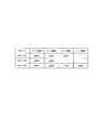
- FIG. 7 is a diagram showing an example of a table for determining the context transfer destination. Such a table is preset for each gNB by, for example, an operator. As shown in FIG.
- the donor gNB candidates are associated with each IAB node.
- the identifier of the candidate of the donor gNB is associated with each identifier related to the IAB node.
- a gNB geographically close to an IAB node is set as a candidate for a donor gNB for that IAB node.
- the table of FIG. 7 shows an example of association with gNB, it may be associated with cell ID.
- the cell ID may be a physical layer cell ID or a global cell ID.
- gNB200-1 may determine gNB200-1 geographically close to IAB node 300-1 as a donor candidate based on the measurement report received from IAB node 300-1.
- the gNB 200-1 may create a table for associating the IAB node 300-1 with the donor gNB candidate of the IAB node 300-1 or update an existing table based on the determined donor candidate.
- step S109 gNB200-1 sends a notification to 5GC10 indicating that a backhaul link connection with IAB node 300-1 has been established.
- the gNB 200-1 may send a request to establish a PDU session for the IAB node to the 5GC10.
- the request for establishing the PDU session may be transmitted from AMF11 to gNB200-1 before step S109 or in step S109.
- FIG. 8 is a diagram showing an example of an exceptional operation sequence in the mobile communication system 1 according to the present embodiment.
- the gNB 200-1 hands over the IAB node 300-1 to the gNB 200-2.
- the IAB node 300-1 establishes an access link connection (RRC connection) with the gNB200-1 by, for example, performing a random access procedure for the gNB200-1.
- the IAB node 300-1 may include the IAB indication in the message (eg, Msg3) sent to the gNB200-1 during the random access procedure.
- the gNB 200-1 acquires the context information regarding the IAB node 300-1 in step S201.
- step S202 the IAB node 300-1 performs an attach procedure to 5GC10 (specifically, AMF11) via gNB200-1.
- 5GC10 specifically, AMF11
- step S203 the IAB node 300-1 transmits the IAB indication to the gNB200-1.
- the IAB node 300-1 includes the IAB indication in the RRC message transmitted to, for example, the gNB200-1.
- Such an RRC message may be a "UE Capability Information" message indicating the capability of the UE.
- step S203 can be omitted.
- step S204 gNB200-1 determines whether or not it has donor ability. If gNB200-1 does not have donor capacity (step S204: NO), gNB200-1 proceeds to step S208.
- step S205 the gNB200-1 transmits the measurement setting for setting the wireless measurement to the IAB node 300-1.
- the IAB node 300-1 performs wireless measurement based on the measurement setting. For example, the IAB node 300-1 measures the received power (received power of the cell-specific reference signal) with respect to the cell of the current serving cell, gNB200-1, and the cell of the adjacent cell, gNB200-2.
- step S206 the IAB node 300-1 transmits a measurement report including the result of the radio measurement to the gNB 200-1.
- step S207 gNB200-1 determines whether itself (gNB200-1) is an appropriate donor gNB or another gNB is an appropriate donor gNB based on the measurement report. If it is determined that itself (gNB200-1) is an appropriate donor gNB (step S207: YES), gNB200-1 proceeds to step S106 of the above-mentioned normal operation sequence (see FIG. 6).
- step S207 if it is determined that the other gNB is an appropriate donor gNB (step S207: NO), gNB200-1 proceeds to step S208.
- the gNB 200-1 transfers the handover request message including the IAB indication received from the IAB node 300-1 to the gNB 200-2 on the Xn interface.
- the gNB 200-1 may include the context information acquired in step S201 in the handover request message.
- the gNB 200-1 may transmit the handover request message with information indicating that the IAB node 300-1 requires the gNB to function as the donor gNB instead of including the IAB indication. Good.
- the gNB 200-1 may transfer the handover request message to the gNB 200-2 on the Xn interface after determining that the gNB 200-2 has the donor ability. Specifically, for example, when gNB200-1 determines in the table shown in FIG.
- the gNB200-1 sends a handover request message to gNB200-2. May be transferred to.
- the handover of the IAB node 300-1 can be executed more quickly.
- information regarding its own donor capacity may be shared in advance between a plurality of gNB 200s adjacent to each other via the Xn interface. Thereby, the gNB 200-1 can identify the adjacent gNB 200 having the donor ability, and can transfer the handover request message to the specified adjacent gNB 200.
- the gNB 200-2 determines whether or not to accept the handover of the IAB node 300-1 in consideration of the IAB indication included in the handover request message.
- the gNB 200-2 may reject the handover request if it does not have the donor ability.
- the description will proceed on the assumption that the gNB 200-2 has determined to accept the handover of the IAB node 300-1.
- step S209 the gNB 200-2 transmits a handover acknowledgment message to the gNB 200-1 on the Xn interface.
- step S210 the gNB 200-1 transmits a handover instruction message (RRC reset message) to the IAB node 300-1 based on the handover acknowledgment message from the gNB 200-2.
- the handover instruction message includes information for designating the handover destination gNB200-2 (cell).
- step S211 the IAB node 300-1 performs a handover to the gNB 200-2 based on the handover instruction message from the gNB 200.
- FIG. 9 is a diagram showing an example of the multi-hop connection sequence in the mobile communication system 1 according to the present embodiment.
- the multi-hop connection sequence is when the IAB node 300-2 or UE100-2 connects to the IAB node 300-1 after the backhaul link connection is connected between the IAB node 300-1 and the gNB200-1. It is a sequence.
- the case where the IAB node 300-2 is connected to the IAB node 300-1 will be mainly described, but the IAB node 300-2 may be appropriately read as the UE 100-2. Further, the description overlapping with the above-mentioned "(1) Normal operation sequence" will be omitted.
- the IAB node 300-2 performs an access link connection (RRC) with the gNB200-1 by performing a random access procedure to the gNB200-1 via the IAB node 300-1. Connection) is established.
- the IAB node 300-2 may include the IAB indication in the message (eg, Msg3) sent to the gNB200-1 during the random access procedure.
- gNB200-1 acquires context information regarding the IAB node 300-2 in step S301.
- the IAB node 300-2 performs an attach procedure to 5GC10 (specifically, AMF11) via the IAB node 300-2 and gNB200-1.
- the IAB node 300-2 may notify the AMF 11 of a notification such as an IAB indication (that is, a notification indicating that it wants to operate as an IAB node).
- the IAB node 300-2 may obtain the candidate list of the donor gNB (cell), the routing information such as the presence / absence of the lower node, and other management information from the AMF11.
- AMF11 may notify each candidate of the donor gNB of context information such as the attachment of the IAB node 300-2 and the routing information of the IAB node 300-2.
- the attach process in step S302 can be omitted. Specifically, the IAB node 300-2 omits the attach process when it is necessary to reestablish the connection with the donor gNB due to the occurrence of some error, such as RRC re-establishment (Reestability).
- step S303 the IAB node 300-2 transmits the IAB indication to the gNB200-1 via the IAB node 300-1.
- the IAB node 300-2 may transmit an IAB instruction in response to a trigger similar to the trigger described in step S103 of "(1) Normal operation sequence" described above.
- the IAB node 300-2 includes the IAB indication in the RRC message transmitted to, for example, gNB200-1.
- Such an RRC message may be a "UE Capability Information" message indicating the ability as a UE.
- step S303 can be omitted.
- the IAB indication may be notified from AMF11 to gNB200-1 in the form of a change in the PDU session resource.
- the AMF may be an AMF for IAB management (dedicated).
- gNB200-1 determines that it is necessary to establish a backhaul link connection between the IAB node 300-1 and the IAB node 300-2 based on the IAB indication.
- step S304 the gNB 200-1 transmits the measurement setting for setting the wireless measurement to the IAB node 300-2.
- the IAB node 300-2 performs wireless measurement based on the measurement setting.
- step S305 the IAB node 300-2 transmits a measurement report including the result of the radio measurement to the gNB 200-1 via the IAB node 300-1.
- gNB200-1 determines whether itself (gNB200-1) is a suitable donor gNB or another gNB is a suitable donor gNB.
- the description will proceed on the assumption that gNB200-1 has determined that it (gNB200-1) is an appropriate donor gNB.
- the processes of steps S304 and S305 are not essential and may be omitted.
- the gNB 200-1 transmits an IAB node setting message (RRC reset message) to the IAB node 300-2.
- the IAB node 300-2 performs a process of establishing a backhaul link connection with the IAB node 300-1 based on the IAB node setting message.
- Such an establishment process includes a process of generating a protocol stack (adaptation / RLC / MAC / PHY entity) for backhaul link and setting parameters based on the setting information in the IAB node setting message.
- Such an establishment process may include a process of preparing a protocol stack on the UE side (for access links) and starting transmission of a synchronization signal or a cell-specific reference signal (or a process of preparing to start transmission).
- step S307 the gNB 200-1 transmits an RRC reset message to the IAB node 300-1.
- the RRC reset message is a message for changing the setting in the IAB node 300-1 with the addition of the IAB node 300-2.
- Such an RRC reset message includes, for example, mapping information indicating the association between the logical channel of the IAB node 300-2 and the logical channel of the backhaul link of the IAB node 300-1. Note that step S307 may be before step S306 or at the same time as step S306.
- step S308 the IAB node 300-2 sends a completion notification message to the gNB 200-1 indicating that the IAB node setting including the establishment of the backhaul link connection with the IAB node 300-1 is completed.
- the IAB node 300-2 behaves as an IAB node rather than acting as a UE with respect to gNB200-1.
- step S309 the IAB node 300-1 sends a completion notification message to the gNB 200-1 indicating that the setting change accompanying the establishment of the backhaul link connection with the IAB node 300-2 has been completed. Note that step S309 may be before step S308 or at the same time as step S308.
- step S310 gNB200-1 transfers the context information of the IAB node 300-2 acquired in step S301 to gNB200-2 on the Xn interface.
- step S311 the gNB 200-1 sends a notification to the 5GC10 indicating that the backhaul link connection of the IAB node 300-2 has been established.
- the gNB 200-1 may send a PDU session establishment request for the IAB node 300-2 to the 5GC10.
- the PDU session establishment request may be transmitted from AMF11 to gNB200-1 before step S311 or in step S311.
- each gNB 200 may provide information to the IAB node 300-1 as to whether or not it has donor capacity.
- the IAB node 300-1 can be connected after selecting the gNB 200 having the donor ability.
- the gNB 200 having donor ability broadcasts information indicating that it has donor ability by including it in a system information block (SIB).
- SIB system information block
- the IAB node 300-1 selects the gNB 200 as the connection destination based on the SIB.
- the IAB node 300-1 may select the gNB 200 as a connection destination when the gNB 200 has a donor ability and the received power from the gNB 200 is equal to or more than the threshold value.
- the IAB node 300-1 may reselect another gNB 200 in response to receiving the SIB transmitted from the gNB 200.
- the IAB node 300-1 performs a random access procedure with the other gNB200 as the connection destination. IAB indications may be sent.
- each gNB 200 has the ability to handle the IAB node 300 in addition to notifying by SIB that it has donor capacity, or in place of notifying by SIB that it has donor capacity. You may notify by SIB that you have. For example, each gNB 200 may notify by SIB that it has a function of handing over the IAB node 300 to another gNB (donor gNB).
- Msg3 is, for example, an RRC Setup Request message.
- the IAB node 300 may include the IAB indication in the establishment case, which is a field (information element) in Msg3.
- the IAB node 300 may notify the IAB indication using the random access preamble (Msg1) transmitted to the gNB 200 during the random access procedure.
- Msg1 the random access preamble
- the PRACH resource may be a time / frequency resource or a signal sequence (preamble sequence).
- the IAB node 300 may notify the IAB indication at a timing other than the random access procedure.
- the IAB node 300 may include the IAB indication in the RRC message such as the UE Assistance Information message.
- the gNB 200 transmits the measurement setting for setting the radio measurement to the IAB node 300 or the UE 100, and receives the measurement report including the result of the radio measurement, whereby the gNB 200 is a suitable donor.
- An example of determining whether the gNB is a gNB or another gNB is an appropriate donor gNB based on the measurement report has been described.
- the gNB 200 is not limited to using the measurement result at the time of such initial connection, and may use the measurement report for changing the network topology or changing the data transfer route.
- the subordinate device directly under the IAB node 300 detects a radio link failure (RLF) with the IAB node 300, it reselects another cell and tries to reestablish the connection to the reselected cell.
- RLF radio link failure
- the IAB node 300 may not be able to grasp that the lower device has detected the RLF.
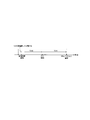
- the lower device detects an out-of-sync state (out-of-sync) N310 times in a row, it detects a radio problem (radio problem).
- the lower device detects a radio problem, it starts a predetermined timer T310.
- the lower device stops the timer T310 when the synchronization state (in-sync) is continuously detected N311 times.
- the timer T310 expires, the lower device detects the RLF, starts the timer T311 and starts the cell reselection operation (connection reestablishment process). Then, when the timer T311 expires without succeeding in reestablishing the connection, the lower device transitions to the RRC idle mode.
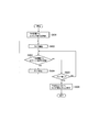
- FIG. 11 is a diagram showing the operation of the IAB node 300 according to the second embodiment.
- the IAB node 300 receives an uplink signal periodically transmitted from a subordinate device directly under the IAB node 300.
- the lower device refers to the UE 100 or another IAB node intervening between the UE 100 and the IAB node 300.
- the uplink signal may be a signal that can be transmitted periodically.
- MAC CE for example, buffer state report
- RRC message for example, measurement report message
- / or uplink reference signal can be used as the uplink signal.
- step S602 the IAB node 300 starts the timer in response to the reception of the uplink signal from the lower device.
- the timer value set in this timer may be the value set from the donor gNB200-1.
- the timer value may be a time longer than the cycle in which the lower device transmits the uplink signal.
- step S603 After starting the timer, when the IAB node 300 receives the uplink signal from the lower device (step S603: YES), the IAB node 300 stops the timer in step S604. In this case, the process returns to step S602 and restarts the timer.
- step S606 the IAB node 300 determines that the lower device has detected the RLF. To do. When the IAB node 300 determines that its lower device has detected the RLF, it may request its higher device to release the wireless bearer (backhaul link) corresponding to this lower device.
- the IAB node 300 can grasp that the RLF is detected in the lower device.
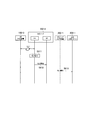
- FIG. 12 is a diagram showing an example of an operation sequence according to the second embodiment.
- the IAB node 300-2 is wirelessly connected to the UE 100-3 as a lower device and the IAB node 300-1 as a higher device, and the UE 100-3 and the IAB node 300-1 are connected. Wirelessly relay communication with and from.
- the base station function unit (DU) wirelessly connects to the UE 100-3
- the user device function unit (MT) wirelessly connects to the IAB node 300-1.
- the lower device may be an IAB node.
- the IAB node 300-2 may be wirelessly connected to the donor device (gNB200-1) without going through the IAB node 300-1.
- the host device and the donor device are the same device.
- step S611 the base station function unit (DU) of the IAB node 300-2 detects a radio link failure (RLF) with the UE 100-3.
- RLF radio link failure
- Such an RLF may be referred to as a Frontal RLF from the perspective of the IAB node 300-2.
- a method based on ACK / NACK from UE 100-3 can be used in addition to the method described above. Specifically, if the base station function unit (DU) of the IAB node 300-2 does not return ACK or NACK from UE100-3 even if the downlink HARQ is retransmitted, for example, the RLF with UE100-3 Is detected.
- DU base station function unit
- the base station function unit (DU) of the IAB node 300-2 provides the state information (RLF notification) indicating that the RLF with the UE 100-3 has been detected to the user device function unit (MT) of the IAB node 300-2.
- This status information (RLF notification) may include an identifier for the UE 100-3, such as a UE identifier and / or a bearer identifier.
- step S613 the user equipment function unit (MT) of the IAB node 300-2 transmits an RRC message including status information (RLF notification) to the donor gNB200-1 via the IAB node 300-1.
- the donor gNB200-1 may release the bearer corresponding to the UE 100-3 based on the state information (RLF notification) included in this RRC message.
- the sequence shown in FIG. 12 may be changed as follows.
- the base station function unit (DU) of the IAB node 300-2 provides state information (RLF notification) indicating that the RLF with the UE 100-3 has been detected in the F1 of the IAB node 300-2.
- state information (RLF notification) may include an identifier for the UE 100-3, such as a UE identifier and / or a bearer identifier.
- the F1-AP entity refers to a communication function unit that communicates with the donor gNB200-1 on the F1 interface, which is the interface of the front hall.
- step S613 the user equipment function unit (MT) of the IAB node 300-2 transmits an F1-AP message including status information (RLF notification) to the donor gNB200-1 via the IAB node 300-1.
- the donor gNB200-1 may release the bearer corresponding to the UE 100-3 based on the state information (RLF notification) included in this F1-AP message.
- the sequence shown in FIG. 12 may be changed as follows.
- step S611 the base station function unit (DU) of the IAB node 300-2 detects that all the lower devices under its control have transitioned to the RRC idle state or the RRC inactive state.
- step S612 the base station function unit (DU) of the IAB node 300-2 provides state information indicating that all the subordinate devices under its control have transitioned to the RRC idle state or the RRC inactive state. Notify the user equipment function unit (MT) or F1-AP entity of.
- the user equipment function unit (MT) or F1-AP entity of the IAB node 300-2 can release its RRC connection based on the state information from the base station function unit (DU).
- the indicated RAI Releasure Assistance Inspection
- Donor gNB200-1 may release the RRC connection of UE100-3 based on this RAI.
- the IAB node 300-2 has notified the donor gNB200-1 of the RLF between itself and the subordinate device.
- the subordinate device may notify the donor gNB200-1 of the RLF detected with the other IAB node.
- FIG. 13 is a diagram showing an operation sequence according to a modified example of the second embodiment.
- another IAB node may intervene between the IAB node 300-2 and the donor gNB200-1.
- step S621 the base station function unit (DU) of the IAB node 300-2 is connected to the IAB node 300-3 from the lower device (UE100-3) connected to the IAB node 300-2.
- This notification may be an RRC Restamination message or an RLF Inspection.
- the UE 100-3 detects the RLF with the IAB node 300-3 and reestablishes the connection with the IAB node 300-2.
- the UE 100-3 transmits an RRC Restabrishment message to the IAB node 300-2.
- This RRC Restamination message is not only the identifier of the UE 100-3, but also the information indicating that the UE 100-3 was connected to the IAB node 300-3 (may be the identifier of the IAB node 300-3), and /. Alternatively, it may include the identifier of the donor device to which the UE 100-3 is connected via the IAB node 300-3 and the like.
- the UE 100-3 detects the RLF with the IAB node 300-3 during the dual connectivity (DC) communication connected at the same time as the IAB nodes 300-3 and 300-2, and sets the RLF index related to this RLF to the IAB node 300 Send to -2.
- this RLF Indication may be called an MCG (Master Cell Group) RLF Indication.
- the RLF Inspection may include an identifier of the UE 100-3, an identifier of the IAB node 300-3, an identifier of the donor device to which the UE 100-3 is connected via the IAB node 300-3, and the like.
- step S622 the base station function unit (DU) of the IAB node 300-2 uses the information included in the notification received from the UE 100-3 in step S621 as the terminal function unit (MT) of the IAB node 300-2 or F1-. Notify the AP entity.
- step S623 the terminal function unit (MT) or F1-AP entity of the IAB node 300-2 transmits a message including the information notified from the base station function unit (DU) to the donor gNB200-1.
- This message is an RRC message or an F1-AP message.
- the donor gNB200-1 determines that the UE 100-3 was under the control of another donor device, that is, belongs to the topology of the other donor device, based on the information contained in the received message, the other donor device is concerned. Notification may be given to the donor device. This notification may include at least one of the identifier of the UE 100-3 and the identifier of the IAB node 300-3.
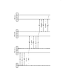
- FIG. 14 is a diagram showing an operation according to the third embodiment.
- "DU” corresponds to the base station function
- "MT" corresponds to the user device function.
- the UE 100-3 transmits uplink data (PDU) to the IAB node 300-2 according to the procedure of steps S701 to S705. Specifically, the UE 100-3 transmits a scheduling request (SR) to the IAB node 300-2 (step S701), receives an allocation of uplink radio resources for BSR transmission (step S702), and transmits the BSR. (Step S703), the uplink radio resource for uplink data transmission is allocated (step S704), and the uplink data is transmitted to the IAB node 300-2 (step S705).
- SR scheduling request
- the IAB node 300-2 transmits uplink data (PDU) to the IAB node 300-1 according to the procedure of steps S706 to S710.
- the IAB node 300-1 transmits uplink data (PDU) to the donor gNB200-1 according to the procedure of steps S711 to S715.
- PDU uplink data
- each IAB node 300 receives a first scheduling request requesting the allocation of uplink radio resources from the lower device. Then, each IAB node 300 transmits a second scheduling request to the higher-level device before receiving the uplink data (PDU) from the lower-level device.
- PDU uplink data
- the scheduling request is triggered when it has the uplink data to be transmitted, but in the present embodiment, the scheduling request is triggered at the stage where the uplink data to be transmitted is not yet possessed. As a result, smooth allocation of uplink radio resources can be realized.
- step S706 when the IAB node 300-2 receives the BSR from the UE 100-3 (step S703), the IAB node 300-2 transmits a scheduling request to the IAB node 300-1.
- the IAB node 300-2 sends the scheduling request to the IAB node 300-1 after receiving the scheduling request from the UE 100-3 (step S701) and before receiving the BSR from the UE 100-3 (step S703). Good.
- the IAB node 300-2 After receiving the scheduling request from the UE 100-3 (step S701), the IAB node 300-2 transmits the scheduling request to the IAB node 300-1 when allocating the uplink radio resource to the UE 100-3 (step S702). (Trigger) may be used.
- the IAB node 300-2 may transmit (trigger) the scheduling request to the IAB node 300-1.
- each IAB node 300 transmits a first buffer state report indicating at least the amount of data that the IAB node 300 can use for uplink transmission to the host device.
- the host device is another IAB node (upper IAB node) or donor gNB200 under the donor gNB200. The host device allocates radio resources for uplink transmission to the IAB node 300 based on the first buffer status report.
- the IAB node 300 has an uplink buffer that temporarily stores data waiting for uplink transmission. For example, the MAC layer of the IAB node 300 notifies the MAC layer of the host device of the first buffer state including information indicating the amount of data in the uplink buffer. The MAC layer of the host device has a scheduler, allocates uplink radio resources to the IAB node 300 based on the first buffer state, and notifies the IAB node 300 of the allocated resources via the control channel.
- the IAB node 300 buffers the uplink data for a plurality of UEs, it is considered that the IAB node 300 has a larger capacity uplink buffer than the UE 100. Therefore, the buffer status report for the IAB node may have a different format from the buffer status report for the UE. Further, the amount of data that can be expressed by the buffer state report for the IAB node (maximum amount of data) may be larger than the amount of data that can be expressed by the buffer state report for the UE (maximum amount of data).
- the buffer status report for the IAB node may include information about the number of UEs 100 under the IAB node 300.
- the IAB node 300 may determine the number of UEs 100 under its own control based on the UE context, C-RNTI (Cell-Radio Network Temporary Identifier), etc., and notifies the number of UEs 100 under its own control from the donor gNB200. May be done.
- the IAB node 300 may include in the buffer status report the number of UEs 100 that have data in its uplink buffer among the UEs 100 under its control. In other words, the IAB node 300 may notify the host device by buffer status reporting how many UEs of uplink data it has.
- the IAB node 300 may include the number of UEs 100 in the RRC connected state among the UEs 100 under its control in the buffer state report.
- the buffer status report for the IAB node takes into account not only the amount of data actually existing in the uplink buffer of the IAB node 300, but also the buffer status report (that is, the potential uplink data amount) from the lower device. You may. As a result, the host device can allocate the uplink radio resource to the IAB node 300 in advance in consideration of the potential uplink data amount, so that the uplink transmission delay due to multi-hop can be suppressed. ..
- the IAB node 300 receives from the subordinate device a second buffer status report indicating the amount of data that the subordinate device can use for uplink transmission. Based on the second buffer status report, the IAB node 300 reports the first buffer status based on the amount of data that it can use for uplink transmission and the amount of data that the lower device can use for uplink transmission. To the host device. For example, the IAB node 300 may include the total value of the amount of data available for uplink transmission by itself and the amount of data available for uplink transmission by the lower device in the first buffer state report. Alternatively, the IAB node 300 has a first BSR value indicating the amount of data available for uplink transmission by itself and a second BSR value indicating the amount of data available to the lower device for uplink transmission. It may be included in the first buffer status report separately.
- the amount of data that the IAB node 300 can use for uplink transmission is the amount of data in its own transmission buffer (MT buffer), the amount of data in its own reception buffer (DU), and / or the amount of buffer in the adaptation entity. May include.
- FIG. 15 is a diagram showing the operation of the IAB node 300 according to the fourth embodiment.
- the IAB node 300 is wirelessly connected to the host device A via the backhaul link.
- the host device A is a host IAB node or donor gNB (donor device).
- the lower devices B1 and B2 are connected to the IAB node 300, and the lower device B3 is connected to the lower device B2.
- the lower device B4 is a device that is not under the control of the IAB node 300.
- the lower devices B1 to B4 are lower IAB nodes or UEs. In the following, when the lower devices B1 to B4 are not particularly distinguished, they are simply referred to as lower devices B.
- the user device function unit (MT) that wirelessly connects to the upper device A is wirelessly connected to the lower device B. Notify the status information to the base station function unit (DU) connected by.
- This state information includes at least one of the RRC state of the user device function unit (MT) and the wireless link state (hereinafter referred to as backhaul link state) between the host device A and the user device function unit (MT). This is information indicating the state of.
- the base station function unit (DU) can control the service provision to the lower device B in consideration of the state on the backhaul link side.
- the RRC state of the user equipment function unit (MT) is either connected, inactive, or idle.
- the backhaul link state is a state based on at least one index among the above 1) to 6) below, or a combination of these indexes.
- RLF state such as detection of RLF and recovery from RLF
- Radio quality such as RSRP (Reference Signal Received Power) 3) Number of RLC (Radio Link Control) retransmissions, number of RACH (Random Access Channel) retransmissions, etc.
- Congestion level such as RSSI (Received Signal Throughput Indicator), CBR (Channel Busy Radio), LBT (Listen Before Talk) status 5) Number of secondary cells set or activated, MIMO (Multi) Output) Number of layers, allocation radio resource status (for example, increase / decrease of Configured grant in quasi-static allocation, increase / decrease of Dynamic grant in dynamic allocation), communication capacity such as throughput measurement value 6) Measurement value of uplink scheduling delay time, Delayed state such as the amount of data in the uplink buffer.
- RSSI Receiveived Signal Throughput Indicator
- CBR Channel Busy Radio
- LBT Listen Before Talk
- MIMO Multi
- allocation radio resource status for example, increase / decrease of Configured grant in quasi-static allocation, increase / decrease of Dynamic grant in dynamic allocation
- communication capacity such as throughput measurement value 6) Measurement value of uplink scheduling delay time, Delayed state such as the amount of data in the uplink buffer.
- the backhaul link state may be a state in which the degree of goodness of the backhaul link state based on the indicators 1) to 6) above, for example, better than the threshold value or worse than the threshold value.
- the user equipment function unit (MT) may notify the base station function unit (DU) of the state information by using a change in the RRC state or a change in the backhaul link state as a trigger. For example, the user equipment function unit (MT) notifies the base station function unit (DU) of the state information when an event that the backhaul link state satisfies the threshold condition occurs.
- the user equipment function unit (MT) may periodically notify the base station function unit (DU) of the status information.
- the base station function unit (DU) may stop providing services to the lower device B based on the status information from the user device function unit (MT). Stopping the service provision to the lower device B means stopping the transmission of at least one downlink radio signal.
- the base station function unit (DU) may stop the transmission of PSS (Primary Synchronization Signal), PSS (Secondary Synchronization Signal), and MIB (Master Information Block).
- the base station function unit (DU) may stop providing services to the lower device B when the user device function unit (MT) transitions to the RRC idle state or the RRC inactive state.
- the base station function unit (DU) may resume the service provision to the lower device B when the user device function unit (MT) transitions to the RRC connected state.
- the base station function unit (DU) may stop providing services to the lower device B when the backhaul link is deteriorated, for example, when RLF is detected in the backhaul.
- the base station function unit (DU) may resume providing services to the lower device B when the backhaul link is improved.
- the base station function unit (DU) may control the radio resource allocation (scheduling) to the lower device B based on the state information from the user device function unit (MT).
- the base station function unit (DU) may cancel the resource allocation to the lower device B when the user device function unit (MT) transitions to the RRC idle state or the RRC inactive state.
- the base station function unit (DU) may allocate uplink resources to the lower device B when the user device function unit (MT) transitions to the RRC idle state or the RRC inactive state.
- the base station function unit (DU) may request the user device function unit (MT) to transition to the RRC connected state.
- the base station function unit (DU) may resume resource allocation to the lower device B when the user device function unit (MT) transitions to the RRC connected state.
- the base station function unit (DU) may cancel the resource allocation to the lower device B when the backhaul link is deteriorated, for example, when RLF is detected in the backhaul.
- the base station function unit (DU) may resume resource allocation to the lower device B when the backhaul link is improved, for example, when the backhaul recovers from the RLF.
- the base station function unit (DU) receives a notification indicating deterioration of the backhaul link, for example, a notification indicating the occurrence of RLF of the backhaul link (hereinafter, RLF) based on the state information from the user device function unit (MT).
- a notification may be transmitted to the lower device B.
- the RLF notification may include the identifier of the IAB node 300.
- the base station function unit (DU) may transmit the RLF notification by the control signal of the layer lower than the RRC layer. This is because the base station function unit (DU) does not have an RRC connection with the lower device B.
- the control signal of the layer lower than the RRC layer is MAC CE (Control Element), RLC Control PDU (Protocol Data Unit), or PDCCH (Physical Downlink Control Channel), but MAC CE will be used below as an example. To do.
- the base station function unit (DU) may transmit the RLF notification to the lower device B by unicast.
- the base station function unit (DU) may transmit the RLF notification by broadcasting or multicast in order to reduce the signaling load of the RLF notification.
- the lower devices B3 and B4 monitor not only the RLF notification from the connected cell (upper IAB node) but also the RLF notification of other cells, so that the lower device B3 and B4 monitor the RLF notification from the IAB node 300. Can be received.
- the base station function unit (DU) may broadcast the RLF notification using, for example, a fixed RNTI (Radio Network Temporary Identifier) defined in advance in the specifications.
- the base station function unit (DU) may transmit the RLF notification by multicast using a common RNTI assigned to a group of lower devices.
- the base station function unit (DU) may notify (broadcast) by SIB whether the RLF notification is transmitted by broadcast / multicast or unicast. Based on this SIB, the lower device B may change the standby mode of the RLF notification, for example, the RNTI used for monitoring the RLF notification.
- the base station function unit (DU) may periodically transmit the RLF notification during the period when the radio link state of the backhaul link is deteriorated, for example, during the period when the RLF of the backhaul link is generated. .. In this case, RLF is generated within the period in which the RLF notification is periodically transmitted.
- the base station function unit (DU) may transmit an RLF notification when an RLF of the backhaul link occurs, and may transmit a notification indicating restoration when the RLF of the backhaul link is restored.
- the lower device B determines that the backhaul link RLF has occurred within the period of receiving the RLF notification from the IAB node 300.
- the transmission cycle of the RLF notification may be set from the donor device to the base station function unit (DU) via the user device function unit (MT) of the IAB node 300.
- the lower device B that has received the RLF notification may start transmitting the ACK / NACK feedback to the IAB node 300 in response to the reception of the RLF notification.
- the IAB node 300 may stop the periodic transmission of the RLF notification.
- the subordinate devices B1 to B3 that have received the RLF notification may perform a process for switching the connection destination or the communication path from the IAB node 300. Examples of such processing include connection reestablishment processing, conditional handover trigger processing, communication path switching processing, and measurement report processing for handover. It should be noted that the lower devices B1 to B3 do not receive the RLF notification from the IAB node 300 (or restore the backhaul RLF) after the switching process is started and before the switching process is completed. When the notification shown is received), it may be determined that the backhaul link of the IAB node 300 has been restored, and the switching process may be stopped.
- the lower devices B1 to B3 that have received the RLF notification perform a cell search for searching for cells other than the cells of the IAB node 300, and reestablish the connection (RRC Restoration) for the appropriate cells.
- RRC Restoration reestablish the connection
- the connection reestablishment process may be controlled so as to be distributed in time.
- the lower devices B1 to B3 distribute the execution start time of the connection reestablishment process of the lower devices B1 to B3 by determining the execution start time of the connection reestablishment process using a random value or the UE-ID. It is possible to prevent load concentration.
- the base station function unit (DU) distributes the transmission timing of the RLF notification to distribute the execution start time of the connection reestablishment processing of the lower devices B1 to B3. May be good.
- the lower devices B1 to B3 that have received the RLF notification are connected to the IAB node 300 and the higher device other than the IAB node 300 to perform DC communication, the lower devices B1 to B3 have another communication path via the IAB node 300. It may be switched to a higher-level device, or RLF notification may be transmitted to another communication device. For example, when the lower device B sets the IAB node 300 as the master node (MN) and the other higher device as the secondary node (SN) for backup, the lower device B switches the communication path via the MN to the SN. ..
- MN master node
- SN secondary node
- the subordinate devices B1 to B3 that have received the RLF notification are set for conditional handover, they may consider that the conditions are satisfied and perform the handover.
- the handover condition is an event indicating deterioration of the radio quality of the serving cell
- the handover may be forcibly triggered by modifying the radio quality measurement result of the serving cell to be low (for example, assuming that it is ⁇ 200 dBm).
- Subordinate devices B1 to B3 that have received the RLF notification may trigger the transmission of the measurement report.
- the general measurement report is transmitted as an RRC message, but the base station function unit (DU) does not have an RRC layer. Therefore, the IAB node 300 retains the measurement report from the lower device B until it recovers from the backhaul link RLF, and transfers it to the donor device when it recovers from the backhaul link RLF (temporarily). The donor device may hand over the lower device B.
- the lower device B4 that has received the RLF notification may perform a process for excluding the IAB node 300 as a candidate for the connection destination.
- the lower device B4 that has received the RLF notification lowers the priority of the cell of the IAB node 300 or excludes it from the reselection target in the cell reselection operation in the RRC idle state or the RRC inactive state, or the IAB node 300.
- Adjust the received power measurement for As a result, the IAB node 300 may be excluded as a candidate for the connection destination.
- an offset value may be applied to the actual received power measurement value.
- the offset value may be a predetermined fixed value.
- the offset value may be a value notified from the network, and the notification may be notified by the notification information (SIB) of the cell in which the lower device B4 is currently camping.
- SIB notification information
- the lower device B4 may perform the process for excluding the IAB node 300 as a candidate for the connection destination at the timing before starting the RRC Set Request process or the RRC Request Request process when transitioning to the RRC connected state. ..
- the lower device B4 confirms whether or not the destination candidate cell has notified the RLF notification before transmitting the RRC Set Request. If the destination candidate cell does not notify the RLF notification, the lower device B4 transmits the RRC Set Request Request. When the destination cell is notifying the RLF notification, the transmission of the RRC Set Request is stopped (or stopped), and the cell reselection operation is performed to select an appropriate RRC Set Request destination.
- the lower device B4 When the lower device B4 no longer receives the RLF notification from the IAB node 300 (or receives a notification indicating the recovery of the backhaul RLF), the lower device B4 determines that the backhaul link of the IAB node 300 has been restored and connects to the connection destination. The process for excluding the IAB node 300 as a candidate for is may be stopped.
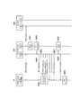
- FIG. 16 is a diagram showing an example of the operation according to the fourth embodiment.
- another IAB node may intervene between the IAB node (Parent IAB node) 300 and the donor gNB (IAB donor) 200.
- step S801 the user equipment function unit (MT) of the IAB node 300 detects a radio problem (radio problem).
- step S802 the user device function unit (MT) of the IAB node 300 detects the RLF (RLF declaration).
- step S803 the user equipment function unit (MT) of the IAB node 300 notifies the base station function unit (DU) of the IAB node 300 of the state information indicating the occurrence of RLF.
- step S804 the base station function unit (DU) of the IAB node 300 starts the periodic transmission of the RLF notification in response to the notification from the user device function unit (MT).
- step S805 the lower device B that has received the RLF notification starts the process for switching the connection destination or the communication path from the IAB node 300.
- a connection reestablishment process (Early RRC Re-estival), a conditional handover trigger process (Triggering Conditional HO), and a communication path switching process (Switching to redundant route).
- step S806 the user device function unit (MT) of the IAB node 300 cannot reestablish the connection, for example, during the operation of the T310, and transitions to the RRC idle state according to the expiration of the T310 (Go to IDLE).
- step S807 the user equipment function unit (MT) of the IAB node 300 notifies the base station function unit (DU) of the IAB node 300 of the state information indicating the transition to the RRC idle state.
- step S808 the base station function unit (DU) of the IAB node 300 stops providing the service to the lower device B in response to the notification from the user device function unit (MT) (Service stopped).
- step S809 the lower device B detects the RLF because the service provision from the IAB node 300 is stopped.
- the base station in the mobile communication system 1 may be an eNB.
- the core network in the mobile communication system 1 may be an EPC (Evolved Packet Core).
- the gNB can be connected to the EPC
- the eNB can be connected to the 5GC
- the gNB and the eNB can be connected via the inter-base station interface (Xn interface, X2 interface).
- a program that causes a computer to execute each process according to the above-described embodiment may be provided.
- the program may also be recorded on a computer-readable medium.
- Computer-readable media can be used to install programs on a computer.
- the computer-readable medium on which the program is recorded may be a non-transient recording medium.
- the non-transient recording medium is not particularly limited, but may be, for example, a recording medium such as a CD-ROM or a DVD-ROM.
- a chipset composed of a memory for storing a program for executing each process performed by the UE 100 and the eNB 200 and a processor for executing the program stored in the memory may be provided.
- IAB node specifications following architecture 1a, including:
- TR identifies in sections 9.7.14 and 9.7.15 the problems caused by the BH RLF of multi-hop radio backhaul.
- a common problem between sections is that the child IAB node / UE is unaware of the BH RLF on the parent IAB node. This can cause BH RLF to occur frequently in high frequency radio backhaul such as FR2 and multi-hopping. As a result, from the user's point of view, the service is significantly interrupted, including delayed recovery of the service.
- TR also identifies potential solutions as follows:
- Option 1 is a general solution for the common problem between sections 9.7.14 and 9.7.15, as BH RLF information is implicitly propagated to child IAB nodes and UEs. Can be considered. Given that BH RLF affects not only the child IAB node, but also the UE (connected to the parent IAB node facing the BH RLF), Option 1 is expected to rely on existing RLF and recovery mechanisms. Therefore, it is an important aspect that Option 1 is supported by the Rel-15 UE. On the other hand, other options will require the functionality of Rel-16. To minimize service interruptions even for Rel-15 UEs, option 1 should be specified as the baseline solution for the BH RLF problem.
- Proposal 1 RAN2 should agree that Option 1, i.e., the IAB node stops service at BH RLF, and Option 1 is also valid for Rel-15 UE, so it is a baseline solution. is there.
- the solution should make it easy to "determine BH RLF also for child nodes".
- the MTs and UEs of the child IAB nodes should declare an RLF if the "service" is interrupted.
- a simple solution is for the parent IAB node under BH RLF to stop transmitting PSS, SSS, MIB, and SIB1. This intentionally creates a radio problem for the child IAB node and the UE.
- Proposal 2 RAN2 should agree that the IAB node will stop transmitting PSS, SSS, MIB, and SIB1 if it decides to discontinue the "service".
- the BH RLF can be considered as an RLF between the MT of the IAB node and the DU of the IAB donor (eg, the DU of the parent IAB node). It can be understood in exactly the same way as using the existing RLF between the UE and gNB. Therefore, the BH RLF is modeled as an RLF in a wireless backhaul link.
- Proposal 3 RAN2 should agree to reuse the existing RLF mechanism in BH RLF.
- Proposal 4 RAN2 should agree that the DU of the IAB node will stop the "service" when the MT enters the RRC IDLE, not when the MT declares an RLF.
- Option 1 is the basis for covering all types of cases and devices, including the UE of Rel-15, and does not mean the best solution in terms of quick recovery of service, etc. .. Therefore, as there are many other features to be defined in this WI, the other options are still beneficial in addition to Option 1 and can be discussed as time permits.
- Findings 1 In addition to Option 1, other options are still beneficial in terms of further improving quality of service.
- the IAB node notifies the downstream node (option 2, option 4) It is useful for the parent IAB node to inform the child IAB node of information related to its BH RLF in order to facilitate the child IAB node to initiate the recovery procedure quickly and / or efficiently.
- the TR may have possible information elements such as "explicitly warn child IAB nodes about upstream RLF" (option 2), or "on backhaul failures including a list of nodes that cannot function as parent nodes" (option 4). ) Capture the information.
- RAN-3 recommends architecture 1a for future normative stages.
- CU is in charge of RRC between DU and CU, and BH RLF is detected by RRC of MT. Therefore, there are two different RRCs to consider.
- the RRC on the MT of the parent IAB node detects the BH RLF, and the different RRCs of the IAB donors generate RRC messages sent to the child IAB nodes.
- the information to the downstream node cannot be transmitted by the RRC message. That is, the RRC message generated by the CU cannot reach the DU due to the BH RLF.
- the "warning" (of option 2) may be sent by MAC CE or the like, but the "list of nodes” (of option 4) is too large and too flexible unless an RRC message is used. Therefore, if option 2 and / or option 4 is introduced, RAN2 should first consider which signaling is used.
- Finding 2 The DU of the IAB node does not have to use the RRC message because the physical wireless link to the CU is broken.
- All IAB nodes share information on a regular basis (option 3)
- the IAB node can detect the BH RLF based on the shared information.
- the information captured by the TR is, for example, "BH quality". This may be the existing GNU-DU STATUS INDICATION of F1 or the new signaling between DUs.
- Option 5 may be aimed at utilizing, for example, multi-connectivity (with MN / SN role changes), conditional handover, or other techniques related to normal topology adaptation or mobility expansion.
- Option 5 is another of this WI or other WI, as stated in the TR that "additional features / extensions defined as part of the other Rel-16 WI may be utilized". You may reuse the results discussed in the topic.
- Findings 5 may reuse the solutions discussed in this WI or other topics in other WIs.
- IAB node following architecture 1a ⁇
- IAB node following architecture 1a ⁇
- IAB node following architecture 1a ⁇
- IAB node following architecture 1a ⁇
- IAB node following architecture 1a ⁇
- IAB node following architecture 1a ⁇
- IAB node following architecture 1a ⁇
- IAB node following architecture 1a ⁇
- IAB node following architecture 1a ⁇
- IAB node following architecture 1a ⁇
- One approach to mitigate such delays consists of initiating an uplink resource request at the IAB node based on the data expected to arrive. Thereby, the IAB node becomes a child. Uplink resources will be available before the IAB node or the UE it serves will receive the actual data. ”, And“ SR / BSR and UL scheduling details and trigger details are in the WI stage. Identify the possible mechanism of "remaining in.”
- RAN2 should extend SR, BSR, and / or UL scheduling for dynamic resource allocation.
- Proposal 1 RAN2 should extend SR, BSR, and / or UL scheduling for dynamic resource allocation in multi-hop radio backhaul.
- SR is triggered when there is no resource for normal BSR transmission as shown below.
- a normal BSR is triggered when data becomes available for transmission, as follows:
- the MAC entity determines the amount of UL data available on the logical channel according to the data volume calculation procedure of TS38.322 and 38.323.
- BSR is triggered when any of the following events occur.
- This UL data belongs to a logical channel with a higher priority than the logical channel containing the available UL data belonging to any LCG. Or -The logical channel belonging to the LCG does not contain available UL data.
- BSR is called "normal BSR".
- Proposal 2 RAN2 should agree that the MT MAC entity needs to consider the amount of UL data visible in the DU of the same IAB node.
- Option 1 The actual amount of data in the buffer in the MAC, RLC, PDCP (and in some cases the adaptation layer) of the DU protocol stack.
- Option 2 In addition to Option 1, the amount of data already granted to the child node / UE (Fig. 18).
- Option 3 In addition to Option 2, the data that can be used for transmission on the child node / UE, that is, the buffer size of the BSR from the child node / UE (FIG. 14).
- option 3 is optimal because it is expected that the MT of the IAB node grants the backhaul link resource when the DU of the IAB node receives UL data from the child node / UE.
- the solution On the other hand, unless the reception of UL grant in MT and the reception of UL data in DU are sufficiently synchronized, resource waste may occur. That is, overscheduling may occur.
- Option 1 has lower risk but lower profit.
- Option 2 is considered a balanced solution among the other options.
- Proposal 3 RAN2 should discuss whether the additional data available for transmission is the amount of data associated with the UL grant to the UE or the BSR from the UE.
- TR also identifies potential solutions as follows:
- R2 has an RLF notification at least in BH Link RLF to the downstream node.
- Alternate links and / or dual connectivity can be used during recovery in the event of a BH Link failure.
- the current UE RLF detection and recovery will be reused as a baseline.
- Option 1 is a general solution for the common problem between sections 9.7.14 and 9.7.15, as BH RLF information is implicitly propagated to child IAB nodes and UEs. Can be considered.
- the agreed "RLF notification” is a feature of Rel-16, but the Rel-15 UE is still allowed to connect to the IAB node. To minimize service interruptions even for Rel-15 UEs, option 1 should be specified as the baseline solution for the BH RLF problem.
- Finding 1 The agreed "RLF notification” cannot solve the BH RLF problem from the perspective of the Rel-15 UE.
- the solution should make it easy to "determine BH RLF also for child nodes".
- a simple solution is for the parent IAB node under BH RLF to stop transmitting PSS, SSS, MIB, and SIB1. This intentionally creates a radio problem for the child IAB node and the UE.
- Proposal 1 RAN2 should agree that the IAB node will stop transmitting PSS, SSS, MIB, and SIB1 if it decides to discontinue the "service".
- RAN2 has already assumed "RRF notification in BH Link RLF" and the current UE behavior is RRC even after declaring RLF, that is, to initiate RRC reestablishment. It is doubtful whether the service actually needs to be stopped at the RLF to stay connected.
- the IAB node should stop the "service” only when the MT enters the RRC IDLE, that is, when the RRC reestablishment fails. In this sense, it is natural for the MT to notify the DU (of the same IAB node) that it will enter RRC IDLE (it may transition to RRC Connected during the setup stage).
- Proposal 2 RAN2 should agree that the DU of the IAB node will stop the "service" when the MT enters the RRC IDLE, not when the MT declares an RLF.
- Proposal 3 If Proposal 2 is agreed, RAN2 further discusses whether MT needs to notify DU (of the same IAB node) if MT enters RRC IDLE.
- the IAB node notifies the downstream node (option 2, option 4) It is useful for the parent IAB node to inform the child IAB node of information related to its BH RLF in order to facilitate the child IAB node to initiate the recovery procedure quickly and / or efficiently.
- the TR may have possible information elements such as "explicitly warn child IAB nodes about upstream RLF" (option 2), or "on backhaul failures including a list of nodes that cannot function as parent nodes" (option 4). ) Capture the information.
- RAN2 agreed to a baseline that "R2 assumes that there is an RLF notification at least in the BH Link RLF to the downstream node".
- RAN-3 recommends architecture 1a for future normative stages.
- CU is in charge of RRC between DU and CU, and BH RLF is detected by RRC of MT. Therefore, there are two different RRCs to consider.
- the RRC on the MT of the parent IAB node detects the BH RLF, and the different RRCs of the IAB donors generate RRC messages sent to the child IAB nodes.
- the information to the downstream node cannot be transmitted by the RRC message. That is, the RRC message generated by the CU cannot reach the DU due to the BH RLF.
- the "warning" (of option 2) may be sent by the MAC CE, but the MAC CE is not appropriate to convey the "list of nodes" (option 4). Therefore, RAN2 should assume option 2 with MAC CE and should not consider option 4.
- Finding 2 The DU of the IAB node does not have to use the RRC message because the physical wireless link to the CU is broken.
- Proposal 4 RAN2 should discuss whether RLF notifications to downstream nodes are sent via MAC CE.
- Proposal 5 RAN2 should agree that the RLF notification will be sent when the DU is notified of the RLF by MT.
- Proposal 6 RAN2 should agree that the MT / UE does not declare the RLF when it receives the RLF notification, it only initiates some backhaul link recovery.
- the "downstream node” naturally means a child node / UE that is directly connected to the parent node.
- the "downstream node” also includes grandchild nodes / UEs that are not directly connected to the parent (that is, the parent is a grandparent from the perspective of the grandchild).
- the grandchild can receive the RLF notification, there is an advantage that the recovery of the topology is quick because the propagation delay of the RLF notification is eliminated.
- any IDLE node / UE can receive RLF notifications, it may be considered during reselection.
- the node / UE cannot connect to the donor node, it is possible to try to avoid reselection or connection of the cell in which BH RLF occurs even if the cell rank is the highest.
- the disadvantage is the complexity of topology adaptation and management.
- Proposal 7 RAN2 should clarify whether the RLF notification is received only by the child node or the grandchild node as well.
- some topology adaptation procedure for example, RRC reestablishment to another IAB node, or switching of the primary path to the redundant route is started.
- the backhaul "link restored" information is useful because the procedure can be stopped if the topology adaptation procedure has not been completed, for example if the RRC reestablishment procedure does not find a suitable cell.
- the RLF notification is repeatedly transmitted during BH RLF, it is not necessary to specify any "other instructions”. This is because if the RLF notification is not sent, BH RLF has not occurred. Otherwise, the "service" will stop. Therefore, the question is whether to repeatedly send RLF notifications during BH RLF.
- Proposal 8 RAN2 should discuss whether RLF notifications are repeatedly transmitted during BH RLF.
- IAB nodes share information on a regular basis (option 3)
- the IAB node can detect the BH RLF based on the shared information.
- the information captured by the TR is, for example, "BH quality". This may be the existing GNU-DU STATUS INDICATION of F1 or the new signaling between DUs.
- Finding 3 Option 3 may be outside the scope of RAN2.
- Option 5 may be aimed at utilizing, for example, multi-connectivity (with MN / SN role changes), conditional handover, or other techniques related to normal topology adaptation or mobility expansion.
- Option 5 is another of this WI or other WI, as stated in the TR that "additional features / extensions defined as part of the other Rel-16 WI may be utilized". You may reuse the results discussed in the topic. Only IAB-specific effects (if any) will be discussed later, such as whether RLF notifications trigger certain actions such as "MCG Fairure Information”.
- Findings 4 may reuse the solutions discussed in this WI or other topics in other WIs.
Landscapes
- Engineering & Computer Science (AREA)
- Computer Networks & Wireless Communication (AREA)
- Signal Processing (AREA)
- Mobile Radio Communication Systems (AREA)
Abstract
Selon un premier mode de réalisation, l'invention porte sur un procédé de commande de communication qui utilise un dispositif de relais pour relayer sans fil une communication entre un dispositif supérieur et un dispositif inférieur. Le procédé de commande de communication comprend une étape à laquelle une unité à fonction de dispositif utilisateur qui se connecte sans fil au dispositif supérieur et constitue une partie du dispositif de relais rapporte des informations d'état à une unité à fonction de station de base qui se connecte sans fil au dispositif inférieur et constitue également une partie du dispositif de relais. Les informations d'état expriment l'état RRC de l'unité à fonction de dispositif utilisateur et/ou l'état de liaison sans fil entre le dispositif supérieur et l'unité à fonction de dispositif utilisateur.
Priority Applications (3)
| Application Number | Priority Date | Filing Date | Title |
|---|---|---|---|
| JP2021509274A JP7303290B2 (ja) | 2019-03-28 | 2020-03-18 | 通信制御方法 |
| US17/483,248 US20220015000A1 (en) | 2019-03-28 | 2021-09-23 | Communication control method |
| JP2023102558A JP7560615B2 (ja) | 2019-03-28 | 2023-06-22 | 通信制御方法、第1中継装置及びプロセッサ |
Applications Claiming Priority (2)
| Application Number | Priority Date | Filing Date | Title |
|---|---|---|---|
| US201962825149P | 2019-03-28 | 2019-03-28 | |
| US62/825,149 | 2019-03-28 |
Related Child Applications (1)
| Application Number | Title | Priority Date | Filing Date |
|---|---|---|---|
| US17/483,248 Continuation US20220015000A1 (en) | 2019-03-28 | 2021-09-23 | Communication control method |
Publications (1)
| Publication Number | Publication Date |
|---|---|
| WO2020196201A1 true WO2020196201A1 (fr) | 2020-10-01 |
Family
ID=72611907
Family Applications (1)
| Application Number | Title | Priority Date | Filing Date |
|---|---|---|---|
| PCT/JP2020/012148 Ceased WO2020196201A1 (fr) | 2019-03-28 | 2020-03-18 | Procédé de commande de communication |
Country Status (3)
| Country | Link |
|---|---|
| US (1) | US20220015000A1 (fr) |
| JP (2) | JP7303290B2 (fr) |
| WO (1) | WO2020196201A1 (fr) |
Cited By (6)
| Publication number | Priority date | Publication date | Assignee | Title |
|---|---|---|---|---|
| JPWO2022085696A1 (fr) * | 2020-10-21 | 2022-04-28 | ||
| JPWO2022149470A1 (fr) * | 2021-01-06 | 2022-07-14 | ||
| JPWO2022168662A1 (fr) * | 2021-02-02 | 2022-08-11 | ||
| JPWO2022234846A1 (fr) * | 2021-05-07 | 2022-11-10 | ||
| EP4258732A4 (fr) * | 2021-01-04 | 2024-05-15 | Kyocera Corporation | Procédé de commande de communication |
| US12621745B2 (en) | 2023-07-03 | 2026-05-05 | Kyocera Corporation | Communication control method |
Families Citing this family (8)
| Publication number | Priority date | Publication date | Assignee | Title |
|---|---|---|---|---|
| CN113728676A (zh) * | 2019-03-29 | 2021-11-30 | 瑞典爱立信有限公司 | 在集成接入和回程网络中的子节点处和父节点处的资源对准 |
| CN114868369A (zh) * | 2019-12-31 | 2022-08-05 | 联想(北京)有限公司 | 用于在通信系统中路由数据的方法及设备 |
| WO2021109355A1 (fr) * | 2020-03-13 | 2021-06-10 | Zte Corporation | Procédés et dispositifs de mise à jour d'une transmission de données pendant une migration inter-donneurs |
| WO2022000259A1 (fr) * | 2020-06-30 | 2022-01-06 | Qualcomm Incorporated | Signalisation d'assistance pour des retransmissions de contrôle de liaison radio |
| WO2022031980A1 (fr) * | 2020-08-06 | 2022-02-10 | Kyungmin Park | Libération de ressources de liaison montante |
| CN118285154A (zh) * | 2022-01-27 | 2024-07-02 | 中兴通讯股份有限公司 | 一种用于网络节点的状态信息指示的方法 |
| FI20225851A1 (en) * | 2022-09-28 | 2024-03-29 | Wirepas Oy | Downlink routing solution for wireless communication networks |
| US20240236820A1 (en) * | 2023-01-05 | 2024-07-11 | Sharp Kabushiki Kaisha | Non-terrestrial network cell information request for cell selection/reselection |
Family Cites Families (5)
| Publication number | Priority date | Publication date | Assignee | Title |
|---|---|---|---|---|
| KR20140072968A (ko) * | 2012-12-05 | 2014-06-16 | 한국전자통신연구원 | 이동 통신 시스템에서 다중 연결을 이용한 단말의 핸드오버 방법 |
| US12082056B2 (en) * | 2017-02-02 | 2024-09-03 | Apple Inc. | Generation Node-B (GNB), user equipment (UE) and methods for handover based on multi-connectivity in new radio (NR) systems |
| WO2020070585A1 (fr) * | 2018-10-05 | 2020-04-09 | Nokia Solutions And Networks Oy | Avance temporelle pour transfert de liaison terrestre sans rach |
| WO2020090988A1 (fr) * | 2018-10-31 | 2020-05-07 | Sharp Kabushiki Kaisha | Procédés et appareil permettant d'utiliser des transferts intercellulaires conditionnels pour une liaison terrestre sans fil |
| US11343737B2 (en) * | 2019-02-06 | 2022-05-24 | Ofinno, Llc | Base station backhaul link information |
-
2020
- 2020-03-18 JP JP2021509274A patent/JP7303290B2/ja active Active
- 2020-03-18 WO PCT/JP2020/012148 patent/WO2020196201A1/fr not_active Ceased
-
2021
- 2021-09-23 US US17/483,248 patent/US20220015000A1/en active Pending
-
2023
- 2023-06-22 JP JP2023102558A patent/JP7560615B2/ja active Active
Non-Patent Citations (7)
| Title |
|---|
| KYOCERA: "Consideration of low latency scheduling for multi-hop backhauling", 3GPP TSG RAN WG2 #105 R2-1900925, 15 February 2019 (2019-02-15), XP051602296 * |
| KYOCERA: "Consideration of low latency scheduling for multi-hop backhauling", 3GPP TSG RAN WG2 #105BIS R2-1903733, 28 March 2019 (2019-03-28), XP051692996 * |
| KYOCERA: "Consideration of topology adaptation upon BH RLF", 3GPP TSG RAN WG2 #105 R2-1900919, 15 February 2019 (2019-02-15), XP051602290 * |
| KYOCERA: "Further consideration of topology adaptation upon BH RLF", 3GPP TSG RAN WG2 #105BIS R2-1903730, 28 March 2019 (2019-03-28), XP051692993 * |
| LG ELECTRONICS INC: "BH RLF reporting to JAB donor node", 3GPP TSG RAN WG2 #105 R2-1902018, 15 February 2019 (2019-02-15), pages 1 - 2, XP051603364 * |
| QUALCOMM INCORPORATED: "Backhaul RLF notification for IAB", 3GPP TSG RAN WG2 #105 R2-1900812, 14 February 2019 (2019-02-14), pages 1 - 3, XP051602186 * |
| ZTE, SANECHIPS: "Discussion on JAB BH RLF handling", 3GPP TSG RAN WG2 #105 R2-1900571, 15 February 2019 (2019-02-15), pages 1 - 6, XP051601951 * |
Cited By (16)
| Publication number | Priority date | Publication date | Assignee | Title |
|---|---|---|---|---|
| EP4224902A4 (fr) * | 2020-10-21 | 2024-05-29 | Kyocera Corporation | Procédé de commande de communication |
| WO2022085696A1 (fr) * | 2020-10-21 | 2022-04-28 | 京セラ株式会社 | Procédé de commande de communication |
| JPWO2022085696A1 (fr) * | 2020-10-21 | 2022-04-28 | ||
| CN116671149B (zh) * | 2020-10-21 | 2026-01-27 | 京瓷株式会社 | 通信控制方法 |
| JP7618689B2 (ja) | 2020-10-21 | 2025-01-21 | 京セラ株式会社 | 通信制御方法 |
| CN116671149A (zh) * | 2020-10-21 | 2023-08-29 | 京瓷株式会社 | 通信控制方法 |
| EP4258732A4 (fr) * | 2021-01-04 | 2024-05-15 | Kyocera Corporation | Procédé de commande de communication |
| JPWO2022149470A1 (fr) * | 2021-01-06 | 2022-07-14 | ||
| WO2022149470A1 (fr) * | 2021-01-06 | 2022-07-14 | 京セラ株式会社 | Procédé de commande de communication |
| JP7586935B2 (ja) | 2021-01-06 | 2024-11-19 | 京セラ株式会社 | 通信制御方法 |
| JPWO2022168662A1 (fr) * | 2021-02-02 | 2022-08-11 | ||
| WO2022168662A1 (fr) * | 2021-02-02 | 2022-08-11 | 株式会社Nttドコモ | Nœud de communication sans fil, système de communication sans fil et procédé de communication sans fil |
| WO2022234846A1 (fr) * | 2021-05-07 | 2022-11-10 | 京セラ株式会社 | Procédé de commande de communication |
| JP7587029B2 (ja) | 2021-05-07 | 2024-11-19 | 京セラ株式会社 | 通信制御方法 |
| JPWO2022234846A1 (fr) * | 2021-05-07 | 2022-11-10 | ||
| US12621745B2 (en) | 2023-07-03 | 2026-05-05 | Kyocera Corporation | Communication control method |
Also Published As
| Publication number | Publication date |
|---|---|
| JP7303290B2 (ja) | 2023-07-04 |
| JP2023120373A (ja) | 2023-08-29 |
| JPWO2020196201A1 (fr) | 2020-10-01 |
| US20220015000A1 (en) | 2022-01-13 |
| JP7560615B2 (ja) | 2024-10-02 |
Similar Documents
| Publication | Publication Date | Title |
|---|---|---|
| JP7560615B2 (ja) | 通信制御方法、第1中継装置及びプロセッサ | |
| JP7413316B2 (ja) | 中継装置 | |
| US20250203696A1 (en) | Relay apparatus | |
| JP6977187B2 (ja) | 通信制御方法 | |
| JP7212199B2 (ja) | 通信制御方法 | |
| JP7667205B2 (ja) | 通信制御方法、第1中継装置、プロセッサ、プログラム、及び移動通信システム | |
| JP7052146B2 (ja) | 通信制御方法 | |
| JP7252367B2 (ja) | 通信制御方法及び無線中継装置 | |
| JPWO2020032129A1 (ja) | 中継装置 | |
| JP2024156993A (ja) | 通信制御方法、中継ノード、プロセッサ、プログラム及びシステム | |
| JP7410167B2 (ja) | 通信制御方法及び無線中継装置 | |
| WO2020158253A1 (fr) | Dispositif de relais et son procédé de commande |
Legal Events
| Date | Code | Title | Description |
|---|---|---|---|
| 121 | Ep: the epo has been informed by wipo that ep was designated in this application |
Ref document number: 20778801 Country of ref document: EP Kind code of ref document: A1 |
|
| ENP | Entry into the national phase |
Ref document number: 2021509274 Country of ref document: JP Kind code of ref document: A |
|
| NENP | Non-entry into the national phase |
Ref country code: DE |
|
| 122 | Ep: pct application non-entry in european phase |
Ref document number: 20778801 Country of ref document: EP Kind code of ref document: A1 |