WO2020196419A1 - 固体高分子形燃料電池用触媒層、膜電極接合体、及び固体高分子形燃料電池 - Google Patents
固体高分子形燃料電池用触媒層、膜電極接合体、及び固体高分子形燃料電池 Download PDFInfo
- Publication number
- WO2020196419A1 WO2020196419A1 PCT/JP2020/012754 JP2020012754W WO2020196419A1 WO 2020196419 A1 WO2020196419 A1 WO 2020196419A1 JP 2020012754 W JP2020012754 W JP 2020012754W WO 2020196419 A1 WO2020196419 A1 WO 2020196419A1
- Authority
- WO
- WIPO (PCT)
- Prior art keywords
- catalyst layer
- polymer electrolyte
- catalyst
- fuel cell
- cross
- Prior art date
- Legal status (The legal status is an assumption and is not a legal conclusion. Google has not performed a legal analysis and makes no representation as to the accuracy of the status listed.)
- Ceased
Links
Images


Classifications
-
- H—ELECTRICITY
- H01—ELECTRIC ELEMENTS
- H01M—PROCESSES OR MEANS, e.g. BATTERIES, FOR THE DIRECT CONVERSION OF CHEMICAL ENERGY INTO ELECTRICAL ENERGY
- H01M4/00—Electrodes
- H01M4/86—Inert electrodes with catalytic activity, e.g. for fuel cells
- H01M4/8647—Inert electrodes with catalytic activity, e.g. for fuel cells consisting of more than one material, e.g. consisting of composites
- H01M4/8657—Inert electrodes with catalytic activity, e.g. for fuel cells consisting of more than one material, e.g. consisting of composites layered
-
- H—ELECTRICITY
- H01—ELECTRIC ELEMENTS
- H01M—PROCESSES OR MEANS, e.g. BATTERIES, FOR THE DIRECT CONVERSION OF CHEMICAL ENERGY INTO ELECTRICAL ENERGY
- H01M8/00—Fuel cells; Manufacture thereof
- H01M8/10—Fuel cells with solid electrolytes
- H01M8/1016—Fuel cells with solid electrolytes characterised by the electrolyte material
- H01M8/1018—Polymeric electrolyte materials
-
- H—ELECTRICITY
- H01—ELECTRIC ELEMENTS
- H01M—PROCESSES OR MEANS, e.g. BATTERIES, FOR THE DIRECT CONVERSION OF CHEMICAL ENERGY INTO ELECTRICAL ENERGY
- H01M4/00—Electrodes
- H01M4/86—Inert electrodes with catalytic activity, e.g. for fuel cells
- H01M4/8647—Inert electrodes with catalytic activity, e.g. for fuel cells consisting of more than one material, e.g. consisting of composites
-
- H—ELECTRICITY
- H01—ELECTRIC ELEMENTS
- H01M—PROCESSES OR MEANS, e.g. BATTERIES, FOR THE DIRECT CONVERSION OF CHEMICAL ENERGY INTO ELECTRICAL ENERGY
- H01M4/00—Electrodes
- H01M4/86—Inert electrodes with catalytic activity, e.g. for fuel cells
- H01M4/88—Processes of manufacture
- H01M4/8803—Supports for the deposition of the catalytic active composition
-
- H—ELECTRICITY
- H01—ELECTRIC ELEMENTS
- H01M—PROCESSES OR MEANS, e.g. BATTERIES, FOR THE DIRECT CONVERSION OF CHEMICAL ENERGY INTO ELECTRICAL ENERGY
- H01M4/00—Electrodes
- H01M4/86—Inert electrodes with catalytic activity, e.g. for fuel cells
- H01M4/88—Processes of manufacture
- H01M4/8803—Supports for the deposition of the catalytic active composition
- H01M4/8807—Gas diffusion layers
-
- H—ELECTRICITY
- H01—ELECTRIC ELEMENTS
- H01M—PROCESSES OR MEANS, e.g. BATTERIES, FOR THE DIRECT CONVERSION OF CHEMICAL ENERGY INTO ELECTRICAL ENERGY
- H01M4/00—Electrodes
- H01M4/86—Inert electrodes with catalytic activity, e.g. for fuel cells
- H01M4/90—Selection of catalytic material
- H01M4/9075—Catalytic material supported on carriers, e.g. powder carriers
- H01M4/9083—Catalytic material supported on carriers, e.g. powder carriers on carbon or graphite
-
- H—ELECTRICITY
- H01—ELECTRIC ELEMENTS
- H01M—PROCESSES OR MEANS, e.g. BATTERIES, FOR THE DIRECT CONVERSION OF CHEMICAL ENERGY INTO ELECTRICAL ENERGY
- H01M4/00—Electrodes
- H01M4/86—Inert electrodes with catalytic activity, e.g. for fuel cells
- H01M4/90—Selection of catalytic material
- H01M4/92—Metals of platinum group
-
- H—ELECTRICITY
- H01—ELECTRIC ELEMENTS
- H01M—PROCESSES OR MEANS, e.g. BATTERIES, FOR THE DIRECT CONVERSION OF CHEMICAL ENERGY INTO ELECTRICAL ENERGY
- H01M8/00—Fuel cells; Manufacture thereof
- H01M8/10—Fuel cells with solid electrolytes
- H01M8/1004—Fuel cells with solid electrolytes characterised by membrane-electrode assemblies [MEA]
-
- H—ELECTRICITY
- H01—ELECTRIC ELEMENTS
- H01M—PROCESSES OR MEANS, e.g. BATTERIES, FOR THE DIRECT CONVERSION OF CHEMICAL ENERGY INTO ELECTRICAL ENERGY
- H01M4/00—Electrodes
- H01M4/86—Inert electrodes with catalytic activity, e.g. for fuel cells
- H01M2004/8678—Inert electrodes with catalytic activity, e.g. for fuel cells characterised by the polarity
-
- H—ELECTRICITY
- H01—ELECTRIC ELEMENTS
- H01M—PROCESSES OR MEANS, e.g. BATTERIES, FOR THE DIRECT CONVERSION OF CHEMICAL ENERGY INTO ELECTRICAL ENERGY
- H01M2300/00—Electrolytes
- H01M2300/0017—Non-aqueous electrolytes
- H01M2300/0065—Solid electrolytes
- H01M2300/0082—Organic polymers
-
- Y—GENERAL TAGGING OF NEW TECHNOLOGICAL DEVELOPMENTS; GENERAL TAGGING OF CROSS-SECTIONAL TECHNOLOGIES SPANNING OVER SEVERAL SECTIONS OF THE IPC; TECHNICAL SUBJECTS COVERED BY FORMER USPC CROSS-REFERENCE ART COLLECTIONS [XRACs] AND DIGESTS
- Y02—TECHNOLOGIES OR APPLICATIONS FOR MITIGATION OR ADAPTATION AGAINST CLIMATE CHANGE
- Y02E—REDUCTION OF GREENHOUSE GAS [GHG] EMISSIONS, RELATED TO ENERGY GENERATION, TRANSMISSION OR DISTRIBUTION
- Y02E60/00—Enabling technologies; Technologies with a potential or indirect contribution to GHG emissions mitigation
- Y02E60/30—Hydrogen technology
- Y02E60/50—Fuel cells
Definitions
- the present invention relates to a catalyst layer for a polymer electrolyte fuel cell, a membrane electrode assembly, and a polymer electrolyte fuel cell.
- a fuel cell is a cell that oxidizes a fuel such as hydrogen with an oxidizing agent such as oxygen and converts the chemical energy associated therewith into electrical energy.
- Fuel cells are classified into alkaline type, phosphoric acid type, polymer type, molten carbonate type, solid oxide type and the like according to the type of electrolyte.
- the polymer electrolyte fuel cell (PEFC) is expected to be applied as a portable power source, a household power source, and an in-vehicle power source because it operates at a low temperature, has a high output density, and can be miniaturized and lightweight. ing.
- the polymer electrolyte fuel cell has a structure in which a polymer electrolyte membrane, which is an electrolyte membrane, is sandwiched between a fuel electrode (anode) and an air electrode (cathode), and a fuel gas containing hydrogen on the fuel electrode side.
- a fuel electrode anode
- an air electrode cathode
- a fuel gas containing hydrogen on the fuel electrode side.
- the anode and cathode each consist of a laminated structure of a catalyst layer and a gas diffusion layer.
- the fuel gas supplied to the anode catalyst layer becomes protons and electrons by the electrode catalyst (reaction 1).
- Protons move to the cathode through the polymer electrolyte and the polymer electrolyte membrane in the anode catalyst layer.
- the electrons pass through an external circuit and move to the cathode.
- protons, electrons, and an oxidant gas supplied from the outside react to generate water (reaction 2). In this way, electrons generate electricity by passing through an external circuit.
- Patent Documents 1 and 2 propose catalyst layers containing carbon or carbon fibers having different particle sizes.
- Patent Document 1 the inclusion of different carbon materials causes pores in the catalyst layer, which can be expected to improve drainage and gas diffusivity.
- the carbon material is only particles, cracks in the catalyst layer are likely to be induced, which may cause a problem of reduced durability.
- Patent Document 2 since fibrous carbon is added in addition to the catalyst-supported carbon, it can be expected that high power generation efficiency can be realized while suppressing cracks in the catalyst layer.
- the power generation performance of a fuel cell varies greatly depending on the size of the pores and the distribution of the pores. Therefore, after all, the method using the combination of carbon fibers still has room for improvement from the viewpoint of improving the power generation performance. There is.
- An object of the present invention is to provide a catalyst layer for a polymer electrolyte fuel cell, a membrane electrode assembly, and a polymer electrolyte fuel cell, which are highly durable and have good durability.
- the catalyst layer for a polymer electrolyte fuel cell is A catalyst layer for a polymer electrolyte fuel cell, which contains a catalyst, carbon particles, a polymer electrolyte, and a fibrous substance, and the carbon particles carry the catalyst.
- the catalyst layer for a polymer electrolyte fuel cell has voids and has voids. Of the voids observed in the cross section in the thickness direction orthogonal to the surface of the catalyst layer, the frequency of the voids having a cross section of 10000 nm 2 or more accounts for 13% or more and 20% or less.
- the maximum cross-sectional area of the gap is preferably 70,000 nm 2 or more and 100,000 nm 2 or less. Further, in the catalyst layer for the polymer electrolyte fuel cell, It is preferable that the total cross section of the gap having a cross section of 10000 nm 2 or more accounts for 40% or more and 50% or less of the total cross section of all the gaps. Further, in the catalyst layer for the polymer electrolyte fuel cell, It is preferable that the average thickness of the catalyst layer in the direction orthogonal to the surface of the catalyst layer is within the range of 1 ⁇ m or more and 30 ⁇ m or less.
- the membrane electrode assembly is An anode catalyst layer and a cathode catalyst layer are provided on both sides of the polymer electrolyte membrane.
- a frame-shaped gasket is provided on the outer periphery of the anode catalyst layer and the cathode catalyst layer.
- At least one of the anode catalyst layer and the cathode catalyst layer is the catalyst layer for polymer electrolyte fuel cells.
- the polymer electrolyte fuel cell according to another aspect of the present invention is It includes the catalyst layer for a polymer electrolyte fuel cell or the membrane electrode assembly.
- the drainage property and the gas diffusivity are improved, cracks in the catalyst layer are suppressed, the utilization efficiency of the catalyst is improved, the high output, the energy conversion efficiency is high, and the solid height with good durability.
- a catalyst layer for a molecular fuel cell, a membrane electrode assembly, and a polymer electrolyte fuel cell can be provided. More specifically, according to one aspect of the present invention, a polymer electrolyte fuel capable of achieving high output by improving gas diffusivity and maintaining long-term performance by having high drainage property.
- a catalyst layer for a battery, a membrane electrode assembly, and a polymer electrolyte fuel cell can be provided.
- FIG. 5 is a schematic view showing a polymer electrolyte fuel cell 11 according to an embodiment of the present invention.
- the polymer electrolyte fuel cell 11 according to the present embodiment has an anode catalyst layer 2 and a cathode catalyst layer 3 on both surfaces of the polymer electrolyte membrane 1, and the anode catalyst layer 2 and the cathode catalyst.
- a membrane electrode assembly 12 having a frame-shaped gasket 4 is provided on the outer periphery of the layer 3, and a gas diffusion layer 5 is arranged so as to face the anode catalyst layer 2 and the cathode catalyst layer 3, respectively, and the anode 6 and the cathode 7 are arranged. Is composed of.
- the separator 10 is made of a conductive and opaque material.
- the separator 10 is formed with a gas flow path 8 for gas flow and a cooling water flow path 9 for cooling water flow on a main surface facing the surface on which the gas flow path 8 is formed. As shown in FIG. 5, the separator 10 is arranged adjacent to the gas diffusion layer 5 so as to sandwich the membrane electrode assembly 12.
- Fuel gas is supplied from the gas flow path 8 of the separator 10 on the anode 6 side.
- the fuel gas include hydrogen gas.
- Oxidizing agent gas is supplied from the gas flow path 8 of the separator 10 on the cathode 7 side.
- a gas containing oxygen such as air is supplied.
- the polymer electrolyte fuel cell 11 according to the present embodiment includes a polymer electrolyte membrane 1, an anode catalyst layer 2, a cathode catalyst layer 3, and a gasket 4 in a set of separators 10.
- the catalyst layer (anode catalyst layer 2, cathode catalyst layer 3) for a polymer electrolyte fuel cell according to the embodiment of the present invention (hereinafter referred to as the present embodiment) includes a catalyst 21 and carbon particles 22. , Polymer electrolyte 23 and fibrous material 24.
- the number, distribution, size, etc. of the pores of the catalyst layer of the present embodiment can be varied depending on the type and mixing ratio of each of the above materials, the liquid preparation method, the coating method, and the like. It is possible to control the voids 25 formed in which they are connected to each other.
- a three-dimensional structure of the catalyst layer is obtained by reconstructing a continuous slice image of FIB-SEM. By extracting the void 25 from this three-dimensional structure, a three-dimensional extracted image of the void 25 can be obtained.
- the void skeleton (broken line portion in FIG. 2) passing through the center of the three-dimensional extraction image of the void 25 is extracted.
- the void cross section can be calculated by using the distance from the surface of the three-dimensional extracted image of the void 25 to the void skeleton.
- the distribution of the void cross section can be obtained by calculating the void cross section (cross section of the void portion) for each one-dimensional skeleton constituting the void skeleton. That is, in the present embodiment, the void cross section, which is the cross section of the void 25, was calculated for each slice image obtained by using the FIB-SEM, and the distribution of the void cross section was obtained.
- the number of reaction points in the catalyst layer increases or decreases depending on the size of the void cross section and the number of one-dimensional skeletons, and as a result, the output of the polymer electrolyte fuel cell can be improved.
- the structure of the catalyst layer can be quantified by drawing a frequency distribution with respect to the cross section of the voids in the catalyst layer. Generally, a graph with a certain section or class on the horizontal axis and frequency or frequency on the vertical axis is called a histogram. Examples of the drawing means include a scatter diagram, a columnar diagram, or a diagram using an approximate line that smoothly connects the points pointed to by them. In the present embodiment, these are collectively referred to as a histogram.
- the fiber length (average fiber length) of the fibrous substance 24 is, for example, 0.1 ⁇ m or more and 200 ⁇ m or less, preferably 0.5 ⁇ m or more and 100 ⁇ m or less, and more preferably 1 ⁇ m or more and 50 ⁇ m or more.
- the strength of the catalyst layer can be increased and cracks can be suppressed during formation.
- the pores in the catalyst layer can be lengthened, and high output can be achieved.
- the reaction points can be increased by passing the gas over a wide range in the catalyst layer.
- the catalyst layer containing the fibrous substance 24 has a large number of pores, and particularly has long pores penetrating the inside of the catalyst layer. Gas fluidity is ensured, resulting in improved power output.
- the fibrous substance 24 contained in the catalyst layer also contributes to flooding (water clogging) in which the water generated in the membrane electrode assembly 12 is not sufficiently discharged and the power generation efficiency is lowered.
- the catalyst layer containing the fibrous substance 24 has a large number of pores, and particularly has long pores penetrating the inside of the catalyst layer. The drainage property is ensured, and the decrease in efficiency of the polymer electrolyte fuel cell 11 can be suppressed.
- the power generation performance can be improved by operating under high humidity with an increased amount of water in the supply gas on the cathode side.
- the above flooding is induced under high humidity, it is necessary to improve the drainage property in the catalyst layer.
- the number of pores can be increased by means such as reducing the ratio of the polymer electrolyte 23, but severe cracks are induced and the catalyst layer is formed. It is not preferable because it makes it difficult to form.
- the fibrous substance 24 when the fibrous substance 24 is used, the structural strength of the catalyst layer is increased, and cracks can be suppressed even when there are many pores in the catalyst layer.
- conductive fibers and electrolyte fibers can be used.
- the conductive fiber include carbon fiber, carbon nanotube, carbon nanohorn, and conductive polymer nanofiber.
- carbon nanofibers or carbon nanotubes are preferable in terms of conductivity and dispersibility.
- the electrolyte fiber is a polymer electrolyte processed into a fibrous form. Proton conductivity can be improved by using an electrolyte fiber as the fibrous substance 24.
- these fibrous substances 24 only one kind may be used alone, two or more kinds may be used in combination, and conductive fibers and electrolyte fibers may be used together.
- the fiber diameter (average fiber diameter) of the fibrous substance 24 is, for example, in the range of 0.5 nm or more and 500 nm or less, preferably 5 nm or more and 400 nm or less, and more preferably 10 nm or more and 300 nm or less. Within the above range, the number of pores in the catalyst layer can be increased, and high output can be achieved.
- the catalyst 21 examples include platinum group elements such as platinum, palladium, ruthenium, iridium, rhodium, and osmium, as well as metals such as iron, lead, copper, chromium, cobalt, nickel, manganese, vanadium, molybdenum, gallium, and aluminum. These alloys, oxides, compound oxides and the like can be used. Among them, platinum and platinum alloy are preferable. Further, the particle size (average particle size D50) of these catalysts 21 is within the range of 0.5 nm or more and 20 nm or less because the activity of the catalyst 21 decreases when the particle size is too large and the stability of the catalyst 21 decreases when the particle size is too small.
- platinum group elements such as platinum, palladium, ruthenium, iridium, rhodium, and osmium
- metals such as iron, lead, copper, chromium, cobalt, nickel, manganese, vanadium, molybdenum, gall
- the particle size of the catalyst 21 (average particle size D50) is more preferably in the range of 1 nm or more and 5 nm or less.
- the particle size of the catalyst 21 can be obtained by, for example, a method of measuring the length of the catalyst particles observed with a transmission electron microscope (TEM) or a small-angle X-ray scattering measurement.
- TEM transmission electron microscope
- the carbon particles 22 are not particularly limited as long as they are fine particles, have conductivity, and are not affected by the catalyst 21.
- examples of the carbon particles 22 include carbon black (acetylene black, furnace black, ketjen black, etc.), graphite, graphite, activated carbon, fullerenes, and the like. If the particle size (average particle size D50) of the carbon particles 22 is too small, it becomes difficult to form an electron conduction path, and if it is too large, the catalyst layer becomes thick and the resistance increases, so that the output characteristics deteriorate. Therefore, the particle size of the carbon particles 22 (average particle size D50) is preferably in the range of 10 nm or more and 1000 nm or less.
- the particle size of the carbon particles 22 (average particle size D50) is more preferably in the range of 10 nm or more and 100 nm or less.
- the particle size of the carbon particles 22 can be obtained, for example, by a method of measuring the length of the carbon particles 22 observed by a scanning electron microscope (SEM) or a transmission electron microscope (TEM), or by measuring the particle size distribution.
- SEM scanning electron microscope
- TEM transmission electron microscope
- the surface area of the carbon particles 22 is obtained, for example, by BET adsorption measurement.
- the polymer electrolyte 23 is not particularly limited as long as it is a resin component having proton conductivity, and among them, a fluorine-based polymer electrolyte or a hydrocarbon-based polymer electrolyte is preferably used.
- a fluorine-based polymer electrolyte or a hydrocarbon-based polymer electrolyte is preferably used.
- the fluorine-based polymer electrolyte for example, Nafion (registered trademark) manufactured by DuPont Co., Ltd. can be used.
- hydrocarbon-based polymer electrolyte for example, an electrolyte such as a sulfonated polyether ketone, a sulfonated polyether sulfone, a sulfonated polyether ether sulfone, a sulfonated polysulfide, or a sulfonated polyphenylene can be used.
- an electrolyte such as a sulfonated polyether ketone, a sulfonated polyether sulfone, a sulfonated polyether ether sulfone, a sulfonated polysulfide, or a sulfonated polyphenylene
- polymer electrolyte 23 it is preferable to select a material having the same quality as that of the polymer electrolyte membrane 1 from the viewpoint of adhesion between the catalyst layer and the polymer electrolyte membrane 1.
- the average thickness of the polymer electrolyte membrane 1 is, for example, 1 ⁇ m or more and 500 ⁇ m or less, preferably 3 ⁇ m or more and 200 ⁇ m or less, and more preferably 5 ⁇ m or more and 100 ⁇ m or less.
- the catalyst layer may be a single layer or a multi-layer structure.
- the catalyst layer has a multi-layer structure
- the thickness of each layer may be the same, or the thickness of each layer may be different.
- the composition of the catalyst 21, carbon particles 22, polymer electrolyte 23, fibrous substance 24, solvent, etc. in each layer may be the same or different.
- the boundary surface of each layer may be flat or may include a curved surface.
- a catalyst layer slurry is prepared, coated and dried on a base material or a gas diffusion layer, and then catalyst is applied to the polymer electrolyte membrane 1. It can be manufactured by heat-bonding the layers.
- the catalyst layer slurry contains a catalyst 21, carbon particles 22, a polymer electrolyte 23, a fibrous substance 24, and a solvent.
- the solvent of the slurry for the catalyst layer is not particularly limited as long as it can dissolve or disperse the polymer electrolyte 23 and the catalyst 21.
- Examples of the solvent for the slurry for the catalyst layer include water, alcohols (methanol, ethanol, 1-propanol, 2-propanol, 1-butanol, 2-butanol, 3-butanol, pentanol, ethylene glycol, diacetone alcohol, etc.
- ketones acetone, methyl ethyl ketone, pentanone, methyl isobutyl ketone, diisobutyl ketone, etc.
- ethers dioxane, tetrahydrofuran, etc.
- sulfoxides dimethyl sulfoxide, etc.
- amides dimethylformamide, etc.
- Dimethylacetamide, etc. Dimethylacetamide, etc.
- the solvent used in the slurry for the catalyst layer is preferably one that can be easily removed by heating, and particularly preferably one having a boiling point of 150 ° C. or lower.
- the concentration of the solute (conductive particles such as carbon particles 22 and catalyst particles such as catalyst 21 and polymer electrolyte 23) in the catalyst layer slurry is, for example, 1% by mass or more and 80% by mass or less, preferably 5% by mass or more. It is used in the range of 60% by mass or less, more preferably 10% by mass or more and 40% by mass or less.
- the polymer electrolyte 23 used in the slurry for the catalyst layer is not particularly limited as long as it is a resin component having proton conductivity, and among them, a fluorine-based polymer electrolyte or a hydrocarbon-based polymer electrolyte is preferably used.
- fluorine-based polymer electrolyte for example, Nafion (registered trademark) manufactured by DuPont Co., Ltd. can be used.
- hydrocarbon-based polymer electrolyte for example, an electrolyte such as a sulfonated polyether ketone, a sulfonated polyether sulfone, a sulfonated polyether ether sulfone, a sulfonated polysulfide, or a sulfonated polyphenylene can be used.
- the catalyst layer slurry can be prepared by mixing the above catalyst 21, carbon particles 22, polymer electrolyte 23, fibrous substance 24, and solvent, and applying a dispersion treatment. Examples of the dispersion method include a method using a ball mill, a bead mill, a roll mill, a shearing mill, a wet mill, ultrasonic dispersion, a homogenizer, and the like.
- a conventional coating method can be used as a method for applying the above catalyst layer slurry onto the substrate.
- Specific coating methods include, for example, roll coaters, air knife coaters, blade coaters, rod coaters, reverse coaters, bar coaters, comma coaters, die coaters, gravure coaters, screen coaters, sprays, spinners and the like. If the same catalyst ink (slurry for the catalyst layer) can be finally applied, there is no particular limitation on the coating means.
- a desired catalyst layer can be obtained by applying the above catalyst layer slurry on a substrate and volatilizing the solvent in the catalyst layer slurry by heating.
- Examples of the method for drying the slurry for the catalyst layer include warm air drying and IR drying.
- the drying temperature is about 40 to 200 ° C., preferably about 40 to 120 ° C.
- the drying time is about 0.5 minutes to 1 hour, preferably about 1 minute to 30 minutes.
- the drying step may be a single drying mechanism, or a plurality of drying mechanisms may be used in combination.
- the average thickness of the catalyst layer obtained by drying the slurry for the catalyst layer is, for example, 0.1 ⁇ m or more and 100 ⁇ m or less, preferably 0.5 ⁇ m or more and 50 ⁇ m or less, more preferably 1 ⁇ m or more and 30 ⁇ m or less, and further preferably 1 ⁇ m or more and 20 ⁇ m or less. Is within the range of. When the thickness of the catalyst layer is 30 ⁇ m or less, cracks are suppressed. Further, when the catalyst layer is used for the polymer electrolyte fuel cell 11, it is suppressed that the diffusivity and conductivity of gas and generated water are lowered, and by extension, the output of the polymer electrolyte fuel cell 11 Is suppressed from decreasing.
- the thickness of the catalyst layer is 1 ⁇ m or more, the thickness of the catalyst layer is less likely to vary, and the distribution of the catalyst substance such as the catalyst 21 and the polymer electrolyte 23 contained in the catalyst layer may become non-uniform. It can be suppressed.
- the cracks on the surface of the catalyst layer and the non-uniformity of the thickness caused the catalyst layer to be used as a part of the polymer electrolyte fuel cell 11 and the polymer electrolyte fuel cell 11 was operated for a long period of time. In some cases, it is not preferable because it is likely to adversely affect the durability of the polymer electrolyte fuel cell 11.
- the thickness of the catalyst layer can be measured, for example, by observing the cross section of the catalyst layer using a scanning electron microscope (SEM).
- SEM scanning electron microscope
- a method for exposing the cross section of the catalyst layer for example, a method such as ion milling and an ultramicrotome can be used.
- the catalyst layer can be formed by heating, and the formed catalyst layer can be transferred to the polymer electrolyte membrane 1. There is no limit.
- Examples of the base material used in the transfer step include polyethylene terephthalate, polyamide, polyimide, polystyrene, polysulfone, polyether sulfone, polyphenylene sulfide, polyether ether ketone, polyetherimide, polybenzoimidazole, polyamideimide, and polyacrylate.
- Polymer films such as polyethylene naphthalate and aramid polypalvanate, or polytetrafluoroethylene, polychlorotrifluoroethylene, polyvinylidene fluoride, ethylene tetrafluoroethylene copolymer, tetrafluoroethylene-hexafluoropropylene copolymer, tetrafluoro
- a heat-resistant fluororesin film such as a perfluoroalkyl vinyl ether copolymer can be used.
- the above-mentioned base material may be a sheet, a film, a plate, a film, or a foil, or at least one of these, which is adhered, adhered, adhered, or bonded, as long as it can be used in the same manner. ..
- the film located on the outermost surface may have an opening.
- opening refers to a portion of the film removed by means such as cutting or punching.
- the shape of the catalyst ink (that is, the electrode) after drying may be formed depending on the shape of the opening.
- a catalyst layer (anode catalyst layer 2 and a cathode catalyst layer 3) is formed on a transfer base material or a gas diffusion layer 5, and a catalyst layer is formed on a polymer electrolyte membrane 1 by thermal pressure bonding.
- a method of forming a catalyst layer directly on the polymer electrolyte membrane 1 can be mentioned. Further, the method of directly forming the catalyst layer on the polymer electrolyte membrane 1 is preferable because the adhesion between the polymer electrolyte membrane 1 and the catalyst layer is high and the catalyst layer is not likely to be crushed.
- the member used for the gasket 4 is not particularly limited as long as it can be coated or bonded with an adhesive material on at least one surface and can be bonded to the polymer electrolyte membrane 1.
- Examples of the member used for the gasket 4 include polyethylene terephthalate, polyamide, polyimide, polystyrene, polysulfone, polyether sulfone, polyphenylene sulfide, polyether ether ketone, polyetherimide, polybenzoimidazole, polyamideimide, polyacrylate, and polyethylene.
- Polymer films such as naphthalate and aramid polypalvanate, or polytetrafluoroethylene, polychlorotrifluoroethylene, polyvinylidene fluoride, ethylene tetrafluoroethylene copolymer, tetrafluoroethylene-hexafluoropropylene copolymer, tetrafluoroper
- a heat-resistant fluororesin film such as a fluoroalkyl vinyl ether copolymer can be used.
- the above-mentioned member may be a sheet, a film, a plate, a film, or a foil, or at least one of these, which is adhered, adhered, adhered, or bonded, as long as it can be used in the same manner.
- the average thickness of the gasket 4 is, for example, 1 ⁇ m or more and 500 ⁇ m or less, preferably 3 ⁇ m or more and 200 ⁇ m or less, and more preferably 5 ⁇ m or more and 100 ⁇ m or less.
- the catalyst layer has voids 25 and is in the thickness direction orthogonal to the surface of the catalyst layer.
- the ratio of the void cross-sectional area of 10000 nm 2 or more occupies 13% or more and 20% or less, and both high power generation performance and suppression of flooding are used.
- the single cell or polymer electrolyte fuel cell manufactured in Japan can exhibit high power generation performance under a wider range of humidification conditions than before.
- the ratio of the frequency of the void cross section of 10000 nm 2 or more in the histogram obtained by dividing the cross section of the void 25 (void portion) of the catalyst layer by 1 section 2500 nm 2. May be 13% or more and 20% or less.
- the frequency of the voids 25 having a cross section of 10000 nm 2 or more occupies.
- the ratio may be 13% or more and 20% or less.
- Example 1 the membrane electrode assembly 12 according to the example based on the present invention and the membrane electrode assembly 12 according to the comparative example will be described.
- Example 1 a platinum-supported carbon catalyst (TEC10E50E, manufactured by Tanaka Kikinzoku Kogyo Co., Ltd.), water, 1-propanol, a polymer electrolyte (Nafion (registered trademark) dispersion, Wako Pure Chemical Industries, Ltd.), and a vapor phase growth fiber A state substance (VGCF (registered trademark), manufactured by Showa Denko Co., Ltd.) was mixed and subjected to dispersion treatment at 500 rpm for 30 minutes using a planetary ball mill to prepare a catalyst ink.
- TEC10E50E manufactured by Tanaka Kikinzoku Kogyo Co., Ltd.
- VGCF vapor phase growth fiber A state substance
- the mass of the polymer electrolyte is 100% by mass with respect to the total mass of the carbon particles and the fibrous substance, the mass of the fibrous substance is 100% by mass with respect to the mass of the carbon particles, and the solid content concentration is 10%.
- a catalyst ink was prepared.
- a coating film was formed by applying the prepared catalyst ink to a thickness of 150 ⁇ m on one side of a polymer electrolyte membrane (Nafion 211 (registered trademark), manufactured by Dupont) using a slit die coater.
- a polymer electrolyte membrane Nafion 211 (registered trademark), manufactured by Dupont
- the polymer electrolyte film on which the coating film was formed was placed in a warm air oven at 80 ° C., and the coating film was dried until the coating film was no longer tacked to form a cathode side electrode catalyst layer.
- a coating film was formed by applying the catalyst ink to the surface opposite to the polymer electrolyte film so as to have a thickness of 50 ⁇ m using a slit die coater.
- Example 1 the membrane electrode assembly of Example 1 was obtained.
- Example 2 When preparing the catalyst ink, instead of carbon nanofibers (VGCF (registered trademark) -H, manufactured by Showa Denko KK), multi-walled carbon nanotubes (diameter 60-100 nm, length> 5 ⁇ m, Tokyo Chemical Industry Co., Ltd.)
- the membrane electrode assembly of Example 2 was obtained by the same method as in Example 1 except that the product was used.
- a membrane electrode assembly of Example 3 was obtained by the same method as in Example 1 except that the amount of carbon nanofibers was halved of that of Example 1 when the catalyst ink was prepared.
- Example 4 A membrane electrode assembly of Example 4 was obtained by the same method as in Example 1 except that the amount of the polymer electrolyte was halved from that of Example 1 when the catalyst ink was prepared.
- Example 5 The catalyst ink was prepared by the same method as in Example 1. A coating film was formed by applying the catalyst ink to the surface of the PTFE film using a slit die coater so as to have a thickness of 150 ⁇ m. Next, the polymer electrolyte membrane on which the coating film was formed was placed in a warm air oven at 80 ° C., and the coating film was dried until the coating film was no longer tacked to obtain a transfer substrate with a cathode side electrode catalyst layer. Next, a coating film was formed by applying the catalyst ink to the surface of another PTFE film using a slit die coater so as to have a thickness of 50 ⁇ m.
- a transfer base material with a cathode side electrode catalyst layer and a transfer base material with an anode side electrode catalyst layer are provided one by one with respect to a pair of surfaces in a polymer electrolyte membrane (Nafion (registered trademark) 211, manufactured by Dupont). It was arranged so as to face each other to form a laminated body. Two electrode catalyst layers were bonded to the polymer electrolyte membrane by hot-pressing the laminate under the conditions of 120 ° C. and 1 MPa. Then, the PTFE film was peeled off from each electrode catalyst layer to obtain a membrane electrode assembly of Example 5.
- Comparative Example 1 In Comparative Example 1, the membrane electrode assembly of Comparative Example 1 was obtained by the same method as in Example 1 except that the vapor-grown fibrous substance was not added.
- Comparative Example 2 A membrane electrode assembly of Comparative Example 2 was obtained by the same method as in Example 1 except that the amount of the vapor-grown fibrous substance was set to 1/10 of that in Example 1 when preparing the catalyst ink. ..
- Comparative Example 3 A membrane electrode assembly of Comparative Example 3 was obtained by the same method as in Example 1 except that the amount of the vapor-grown fibrous substance was three times that of Example 1 when the catalyst ink was prepared.
- the ratio of the frequency of the cross section of the voids of 10000 nm 2 or more (the cross section of the voids), the maximum value of the cross section of the voids, and the total of the cross sections of the voids of 10000 nm 2 or more are the total void cross sections.
- Table 1 shows a list of the ratio to (total cross-section of all voids), average thickness of cathode catalyst layer, power generation performance, and durability evaluation results.
- Example 5 it was found that the ratio of the frequency of the cross-sectional area of the void portion of 10000 nm 2 or more was included in the range of 13% or more and 20% or less. Further, in Example 3, the maximum value of the cross-sectional area of the gap portion is at 70000Nm 2 or more 100000 2 or less, the gap portion is the sum of the cross-sectional area is 10000 nm 2 or more, the total void cross-sectional area (air gap all cross It was found that it occupies 40% or more and 50% or less of the total area). As a result, in all of Examples 1 to 5, it was confirmed that the power generation performance was " ⁇ " and the durability was " ⁇ " regardless of the conditions at the time of measurement. That is, it was recognized that the membrane electrode assembly of Examples 1 to 5 is a membrane electrode assembly capable of forming a fuel cell having excellent power generation performance and durability.
- Comparative Examples 1 to 3 in which the ratio of the frequency of the void cross section of 10000 nm 2 or more is not included in the range of 13% or more and 20% or less, the power generation performance is improved under either the standard condition or the high humidity condition. It was recognized as "x". It is presumed that this is because the distribution of the cross-section of the voids is biased toward the small area side, which reduces drainage and durability, or is biased toward the large area side, which reduces the performance due to the decrease in active sites.
- the void cross section of 10000 nm 2 or more By using a membrane electrode assembly in which the frequency accounts for 13% or more of the total frequency, it is possible to exhibit high power generation performance, suppress flooding, and improve durability.
- the catalyst layer for polymer electrolyte fuel cells, the membrane electrode assembly, and the catalyst layer for polymer electrolyte fuel cells which can achieve high output by improving gas diffusivity and can maintain long-term performance by having high drainage.
- the contents of the catalyst 21, carbon particles 22, the polymer electrolyte 23, and the fibrous substance 24 constituting the catalyst layer may be set to optimum values.
- the numerical range may be set to "13% or more and 20% or less" by paying attention to "the ratio of the frequency of the cross-sectional area of the void portion of 10000 nm 2 or more".
- a catalyst layer, a membrane electrode assembly, and a solid polymer type that can achieve high output by improving gas diffusivity and can maintain long-term performance by having high drainage property.
- a fuel cell can be provided.
- the present embodiment can also provide a cell cell and a fuel cell stack provided with the catalyst layer for a polymer electrolyte fuel cell or the membrane electrode assembly. Therefore, this embodiment can be suitably used for a stationary cogeneration system, a fuel cell vehicle, or the like using a polymer electrolyte fuel cell, and has great industrial utility value.
Landscapes
- Chemical & Material Sciences (AREA)
- Chemical Kinetics & Catalysis (AREA)
- General Chemical & Material Sciences (AREA)
- Electrochemistry (AREA)
- Engineering & Computer Science (AREA)
- Manufacturing & Machinery (AREA)
- Sustainable Development (AREA)
- Sustainable Energy (AREA)
- Life Sciences & Earth Sciences (AREA)
- Materials Engineering (AREA)
- Composite Materials (AREA)
- Inert Electrodes (AREA)
- Fuel Cell (AREA)
Abstract
本発明は、排水性やガス拡散性を向上すると共に触媒層のクラックを抑制し、触媒の利用効率を高め、高出力でエネルギー変換効率が高く、耐久性の良好な固体高分子形燃料電池用触媒層、膜電極接合体、及び固体高分子形燃料電池を提供する。本実施形態の固体高分子形燃料電池用触媒層は、触媒21、炭素粒子22、高分子電解質23及び繊維状物質24を含み、炭素粒子22が触媒21を担持しており、固体高分子形燃料電池用触媒層は、空隙25を有し、固体高分子形燃料電池用触媒層の表面と直交する厚さ方向における断面において観察される空隙25のうち、10000nm2以上の断面積を有する空隙25の頻度が占める割合が13%以上20%以下である。
Description
本発明は、高分子形燃料電池用触媒層、膜電極接合体、及び固体高分子形燃料電池に関する。
近年、環境問題やエネルギー問題の有効な解決策として、燃料電池が注目を浴びている。燃料電池とは、水素などの燃料を酸素などの酸化剤を用いて酸化し、これに伴う化学エネルギーを電気エネルギーに変換する電池をいう。
燃料電池は、電解質の種類によって、アルカリ形、リン酸形、高分子形、溶融炭酸塩形、固体酸化物形などに分類される。固体高分子形燃料電池(PEFC)は、低温作動、高出力密度であり、小型化・軽量化が可能であることから、携帯用電源、家庭用電源、車載用動力源としての応用が期待されている。
燃料電池は、電解質の種類によって、アルカリ形、リン酸形、高分子形、溶融炭酸塩形、固体酸化物形などに分類される。固体高分子形燃料電池(PEFC)は、低温作動、高出力密度であり、小型化・軽量化が可能であることから、携帯用電源、家庭用電源、車載用動力源としての応用が期待されている。
固体高分子形燃料電池(PEFC)は、電解質膜である高分子電解質膜を燃料極(アノード)と空気極(カソード)で挟んだ構造となっており、燃料極側に水素を含む燃料ガス、空気極側に酸素を含む酸化剤ガスを供給することで、下記の電気化学反応により発電する。
アノード:H2 → 2H++2e- ・・・(反応1)
カソード:1/2O2 + 2H+ + 2e- → H2O ・・・(反応2)
アノード:H2 → 2H++2e- ・・・(反応1)
カソード:1/2O2 + 2H+ + 2e- → H2O ・・・(反応2)
アノードおよびカソードは、それぞれ触媒層とガス拡散層の積層構造からなる。アノード触媒層に供給された燃料ガスは、電極触媒によりプロトンと電子となる(反応1)。プロトンは、アノード触媒層内の高分子電解質、高分子電解質膜を通り、カソードに移動する。電子は、外部回路を通り、カソードに移動する。カソード触媒層では、プロトンと電子と外部から供給された酸化剤ガスが反応して水を生成する(反応2)。このように、電子が外部回路を通ることにより発電する。
現在、燃料電池の低コスト化に向けて、高出力特性を示す燃料電池が望まれている。しかし、高出力運転においては多くの生成水が発生するため、触媒層やガス拡散層に水が溢れ、ガスの供給が妨げられるフラッディングが生じうる。このことにより、従来技術の燃料電池には、燃料電池の出力が著しく低下する場合があるという課題がある。
上記課題に対し、特許文献1、2では、異なる粒子径のカーボンまたはカーボン繊維を含む触媒層が提案されている。
上記課題に対し、特許文献1、2では、異なる粒子径のカーボンまたはカーボン繊維を含む触媒層が提案されている。
特許文献1では、異なるカーボン材料を含むことにより触媒層内に空孔が生じ、排水性やガス拡散性の向上が期待できる。しかし、カーボン材料が粒子のみの場合、触媒層のクラックが誘発されやすく、それに伴う耐久性の低下が問題となることがある。
また特許文献2では、触媒担持カーボンの他に繊維状カーボンを添加しているため、触媒層のクラックを抑制しながら高い発電効率を実現できると期待できる。しかし、燃料電池における発電性能は、細孔の大きさや細孔の分布によって大きく変わるものであるから、結局のところ、カーボン繊維の組み合わせを用いる方法では、発電性能を高める観点において、依然として改良の余地がある。
また特許文献2では、触媒担持カーボンの他に繊維状カーボンを添加しているため、触媒層のクラックを抑制しながら高い発電効率を実現できると期待できる。しかし、燃料電池における発電性能は、細孔の大きさや細孔の分布によって大きく変わるものであるから、結局のところ、カーボン繊維の組み合わせを用いる方法では、発電性能を高める観点において、依然として改良の余地がある。
本発明は、このような事情に鑑みてなされたものであって、排水性やガス拡散性を向上すると共に触媒層のクラックを抑制し、触媒の利用効率を高め、高出力でエネルギー変換効率が高く、耐久性の良好な固体高分子形燃料電池用触媒層、膜電極接合体、及び固体高分子形燃料電池を提供することを目的とする。
上記の課題を解決するための手段として、本発明の一態様に係る固体高分子形燃料電池用触媒層は、
触媒、炭素粒子、高分子電解質及び繊維状物質を含み、上記炭素粒子が上記触媒を担持している固体高分子形燃料電池用触媒層であって、
上記固体高分子形燃料電池用触媒層は、空隙部を有し、
上記触媒層の表面と直交する厚さ方向における断面において観察される上記空隙部のうち、10000nm2以上の断面積を有する上記空隙部の頻度が占める割合が13%以上20%以下である。
触媒、炭素粒子、高分子電解質及び繊維状物質を含み、上記炭素粒子が上記触媒を担持している固体高分子形燃料電池用触媒層であって、
上記固体高分子形燃料電池用触媒層は、空隙部を有し、
上記触媒層の表面と直交する厚さ方向における断面において観察される上記空隙部のうち、10000nm2以上の断面積を有する上記空隙部の頻度が占める割合が13%以上20%以下である。
ここで、上記固体高分子形燃料電池用触媒層においては、
上記空隙部の断面積の最大値が70000nm2以上100000nm2以下であることが好ましい。
また、上記固体高分子形燃料電池用触媒層においては、
上記空隙部のうち断面積が10000nm2以上である上記空隙部の断面積の総和が、上記空隙部全ての断面積の総和に対して40%以上50%以下を占めることが好ましい。
また、上記固体高分子形燃料電池用触媒層においては、
上記触媒層の表面と直交する方向における上記触媒層の平均厚みが、1μm以上30μm以下の範囲内となるように構成されていることが好ましい。
上記空隙部の断面積の最大値が70000nm2以上100000nm2以下であることが好ましい。
また、上記固体高分子形燃料電池用触媒層においては、
上記空隙部のうち断面積が10000nm2以上である上記空隙部の断面積の総和が、上記空隙部全ての断面積の総和に対して40%以上50%以下を占めることが好ましい。
また、上記固体高分子形燃料電池用触媒層においては、
上記触媒層の表面と直交する方向における上記触媒層の平均厚みが、1μm以上30μm以下の範囲内となるように構成されていることが好ましい。
また、本発明の他の態様に係る膜電極接合体は、
高分子電解質膜の両面にアノード触媒層及びカソード触媒層を具備し、
上記アノード触媒層及び上記カソード触媒層の外周に額縁状のガスケットを具備し、
上記アノード触媒層若しくは上記カソード触媒層の少なくとも一方が、上記固体高分子形燃料電池用触媒層である。
また、本発明の他の態様に係る固体高分子形燃料電池は、
上記固体高分子形燃料電池用触媒層または上記膜電極接合体を備えている。
高分子電解質膜の両面にアノード触媒層及びカソード触媒層を具備し、
上記アノード触媒層及び上記カソード触媒層の外周に額縁状のガスケットを具備し、
上記アノード触媒層若しくは上記カソード触媒層の少なくとも一方が、上記固体高分子形燃料電池用触媒層である。
また、本発明の他の態様に係る固体高分子形燃料電池は、
上記固体高分子形燃料電池用触媒層または上記膜電極接合体を備えている。
本発明の一態様によれば、排水性やガス拡散性を向上すると共に触媒層のクラックを抑制し、触媒の利用効率を高め、高出力でエネルギー変換効率が高く、耐久性の良好な固体高分子形燃料電池用触媒層、膜電極接合体、及び固体高分子形燃料電池を提供することができる。より詳しくは、本発明の一態様によれば、ガス拡散性を向上させることで高出力化を実現し、且つ高い排水性も有することにより長期的な性能維持が可能な、固体高分子形燃料電池用触媒層、膜電極接合体、及び固体高分子形燃料電池を提供することができる。
以下、本発明を詳細に説明する。なお、本発明は、以下に記載する各実施の形態に限定されうるものではなく、当業者の知識に基づいて設計の変更等の変形を加えることも可能であり、そのような変形が加えられた実施の形態も本発明の範囲に含まれるものである。
まず、本発明の一実施形態が適用されうる固体高分子形燃料電池用触媒層(以下、触媒層ということがある)及び膜電極接合体を使用した、固体高分子形燃料電池について説明する。
まず、本発明の一実施形態が適用されうる固体高分子形燃料電池用触媒層(以下、触媒層ということがある)及び膜電極接合体を使用した、固体高分子形燃料電池について説明する。
(固体高分子形燃料電池の全体構成)
図5は、本発明の一実施形態に係る固体高分子形燃料電池11を示す概略図である。図5に示されるように、本実施形態に係る固体高分子形燃料電池11は、高分子電解質膜1の両面にアノード触媒層2及びカソード触媒層3を有し、アノード触媒層2及びカソード触媒層3の外周に枠状のガスケット4を具備した膜電極接合体12を備え、アノード触媒層2及びカソード触媒層3と対向してガス拡散層5が配置されてなり、それぞれアノード6およびカソード7が構成されてなる。セパレータ10は、導電性を有し、かつ不透過性の材料よりなる。セパレータ10には、ガス流通用のガス流路8と、ガス流路8の形成された面と相対する主面に冷却水流通用の冷却水流路9が形成されてなる。図5に示されるように、セパレータ10はガス拡散層5に隣接し、膜電極接合体12を挟持するよう配置される。
図5は、本発明の一実施形態に係る固体高分子形燃料電池11を示す概略図である。図5に示されるように、本実施形態に係る固体高分子形燃料電池11は、高分子電解質膜1の両面にアノード触媒層2及びカソード触媒層3を有し、アノード触媒層2及びカソード触媒層3の外周に枠状のガスケット4を具備した膜電極接合体12を備え、アノード触媒層2及びカソード触媒層3と対向してガス拡散層5が配置されてなり、それぞれアノード6およびカソード7が構成されてなる。セパレータ10は、導電性を有し、かつ不透過性の材料よりなる。セパレータ10には、ガス流通用のガス流路8と、ガス流路8の形成された面と相対する主面に冷却水流通用の冷却水流路9が形成されてなる。図5に示されるように、セパレータ10はガス拡散層5に隣接し、膜電極接合体12を挟持するよう配置される。
アノード6側のセパレータ10のガス流路8からは燃料ガスが供給される。燃料ガスとしては、例えば水素ガスが挙げられる。カソード7側のセパレータ10のガス流路8からは、酸化剤ガスが供給される。酸化剤ガスとしては、例えば空気などの酸素を含むガスが供給される。
図5に示すように、本実施形態に係る固体高分子形燃料電池11は、1組のセパレータ10に、高分子電解質膜1と、アノード触媒層2と、カソード触媒層3と、ガスケット4と、ガス拡散層5とが挟持された、いわゆる単セル構造の固体高分子形燃料電池である。しかしながら、本実施の形態では、セパレータ10を介して複数のセルを直列に積層したスタック構造を採用することもできる。
図5に示すように、本実施形態に係る固体高分子形燃料電池11は、1組のセパレータ10に、高分子電解質膜1と、アノード触媒層2と、カソード触媒層3と、ガスケット4と、ガス拡散層5とが挟持された、いわゆる単セル構造の固体高分子形燃料電池である。しかしながら、本実施の形態では、セパレータ10を介して複数のセルを直列に積層したスタック構造を採用することもできる。
(固体高分子形燃料電池用触媒層の構成)
図1に示すように、本発明の実施の形態(以下、本実施形態)に係る固体高分子形燃料電池用触媒層(アノード触媒層2、カソード触媒層3)は、触媒21、炭素粒子22、高分子電解質23及び繊維状物質24を含む。
上記の各材料の種類や混合比、及び調液方法や塗工方法等により、本実施形態の触媒層が有する空孔の数、分布、大きさ等を変動させることができ、それにより空孔同士が連なって形成される空隙25を制御することができる。
図1に示すように、本発明の実施の形態(以下、本実施形態)に係る固体高分子形燃料電池用触媒層(アノード触媒層2、カソード触媒層3)は、触媒21、炭素粒子22、高分子電解質23及び繊維状物質24を含む。
上記の各材料の種類や混合比、及び調液方法や塗工方法等により、本実施形態の触媒層が有する空孔の数、分布、大きさ等を変動させることができ、それにより空孔同士が連なって形成される空隙25を制御することができる。
(空隙断面積の算出方法)
FIB-SEMの連続スライス像を再構築することにより、触媒層の三次元構造を得る。この三次元構造から空隙25を抽出することにより、空隙25の三次元抽出像を得ることができる。
次に、図2に示すように空隙25の三次元抽出像の中心を通る空隙骨格(図2中の破線部)を抽出する。空隙25の三次元抽出像の表面から空隙骨格までの距離を用いることで空隙断面積を算出できる。空隙骨格を構成する一次元骨格ごとに空隙断面積(空隙部の断面積)を算出することにより、空隙断面積の分布を得ることができる。つまり、本実施形態では、FIB-SEMを用いて得た各スライス像について空隙25の断面積である空隙断面積をそれぞれ算出し、その空隙断面積についての分布を得た。
FIB-SEMの連続スライス像を再構築することにより、触媒層の三次元構造を得る。この三次元構造から空隙25を抽出することにより、空隙25の三次元抽出像を得ることができる。
次に、図2に示すように空隙25の三次元抽出像の中心を通る空隙骨格(図2中の破線部)を抽出する。空隙25の三次元抽出像の表面から空隙骨格までの距離を用いることで空隙断面積を算出できる。空隙骨格を構成する一次元骨格ごとに空隙断面積(空隙部の断面積)を算出することにより、空隙断面積の分布を得ることができる。つまり、本実施形態では、FIB-SEMを用いて得た各スライス像について空隙25の断面積である空隙断面積をそれぞれ算出し、その空隙断面積についての分布を得た。
空隙断面積の大きさや一次元骨格の数に伴って触媒層内の反応点が増減し、その結果として固体高分子形燃料電池の出力を向上させることができる。
触媒層内の空隙断面積に対する度数分布を描くことで、触媒層の構造を定量化することができる。
一般的に、横軸に一定の区間もしくは階級、縦軸に度数もしくは頻度をとったグラフをヒストグラムと呼ぶ。描画の手段として、散布図、柱状図もしくはそれらが指す点を滑らかに結んだ近似線による線図等が挙げられるが、本実施形態ではそれらを総称してヒストグラムと記載する。
触媒層内の空隙断面積に対する度数分布を描くことで、触媒層の構造を定量化することができる。
一般的に、横軸に一定の区間もしくは階級、縦軸に度数もしくは頻度をとったグラフをヒストグラムと呼ぶ。描画の手段として、散布図、柱状図もしくはそれらが指す点を滑らかに結んだ近似線による線図等が挙げられるが、本実施形態ではそれらを総称してヒストグラムと記載する。
以下、固体高分子形燃料電池用触媒層を構成する各材料について説明する。
(繊維状物質)
繊維状物質24の繊維長(平均繊維長)は例えば0.1μm以上200μm以下、好ましくは0.5μm以上100μm以下、更に好ましくは1μm以上50μm以上の範囲内である。上記範囲にすることにより、触媒層の強度を高めることができ、形成時にクラックが生じることを抑制できる。また、触媒層内の空孔を長大化させることができ、高出力化が可能になる。
上述したように、固体高分子形燃料電池11では燃料ガス及び酸化剤ガスが持続的に供給されるため、触媒層内の広範囲に渡ってガスを通過させることにより反応点を増やすことができる。
(繊維状物質)
繊維状物質24の繊維長(平均繊維長)は例えば0.1μm以上200μm以下、好ましくは0.5μm以上100μm以下、更に好ましくは1μm以上50μm以上の範囲内である。上記範囲にすることにより、触媒層の強度を高めることができ、形成時にクラックが生じることを抑制できる。また、触媒層内の空孔を長大化させることができ、高出力化が可能になる。
上述したように、固体高分子形燃料電池11では燃料ガス及び酸化剤ガスが持続的に供給されるため、触媒層内の広範囲に渡ってガスを通過させることにより反応点を増やすことができる。
繊維状物質24を含まない触媒層と比較して、繊維状物質24を含む触媒層は多数の空孔を有し、特に触媒層内を貫通する長い空孔を有することから、触媒層内のガス流動性が確保され、その結果として出力が向上する。
同様に、膜電極接合体12内に発生した水が充分に排出されず、発電効率が低下するフラッディング(水詰まり)に関しても、触媒層に含まれる繊維状物質24が寄与する。
繊維状物質24を含まない触媒層と比較して、繊維状物質24を含む触媒層は多数の空孔を有し、特に触媒層内を貫通する長い空孔を有することから、触媒層内の排水性が確保され、固体高分子形燃料電池11の効率低下を抑制できる。
同様に、膜電極接合体12内に発生した水が充分に排出されず、発電効率が低下するフラッディング(水詰まり)に関しても、触媒層に含まれる繊維状物質24が寄与する。
繊維状物質24を含まない触媒層と比較して、繊維状物質24を含む触媒層は多数の空孔を有し、特に触媒層内を貫通する長い空孔を有することから、触媒層内の排水性が確保され、固体高分子形燃料電池11の効率低下を抑制できる。
低湿度下の運転条件では、アノード側の乾燥(ドライアウト現象)により、発電性能が低下しやすい。そのため、カソード側の供給ガス中の水分を増やした高湿度下の運転を行うことで、発電性能を向上させることができる。しかしながら、高湿度下では上記のフラッディングを誘発するため、触媒層内の排水性を向上させる必要がある。
触媒21、炭素粒子22、高分子電解質23のみからなる触媒層の場合でも、高分子電解質23の比率を小さくする等の手段で空孔を増やすことはできるが、激しいクラックが誘発されて触媒層の形成が困難になるなど、好ましくない。
しかしながら、繊維状物質24を用いた場合には触媒層の構造的な強度が増し、触媒層内の空孔が多い場合でもクラックを抑制することが可能となる。
触媒21、炭素粒子22、高分子電解質23のみからなる触媒層の場合でも、高分子電解質23の比率を小さくする等の手段で空孔を増やすことはできるが、激しいクラックが誘発されて触媒層の形成が困難になるなど、好ましくない。
しかしながら、繊維状物質24を用いた場合には触媒層の構造的な強度が増し、触媒層内の空孔が多い場合でもクラックを抑制することが可能となる。
繊維状物質24としては、導電性繊維や電解質繊維が使用できる。導電性繊維としては、例えば、カーボンファイバー、カーボンナノチューブ、カーボンナノホーン、導電性高分子ナノファイバー等が例示できる。特に、導電性や分散性の点でカーボンナノファイバー又はカーボンナノチューブが好ましい。また、電解質繊維は高分子電解質を繊維状に加工したものである。繊維状物質24として電解質繊維を用いることでプロトン伝導性を向上することができる。更に、これらの繊維状物質24は、一種のみを単独で使用してもよいが、二種以上を併用してもよく、導電性繊維と電解質繊維を併せて用いてもよい。
繊維状物質24の繊維径(平均繊維径)としては、例えば0.5nm以上500nm以下、好ましくは5nm以上400nm以下、更に好ましくは10nm以上300nm以下の範囲内である。上記範囲にすることにより、触媒層内の空孔を増加させることができ、高出力化が可能になる。
繊維状物質24の繊維径(平均繊維径)としては、例えば0.5nm以上500nm以下、好ましくは5nm以上400nm以下、更に好ましくは10nm以上300nm以下の範囲内である。上記範囲にすることにより、触媒層内の空孔を増加させることができ、高出力化が可能になる。
(触媒)
触媒21としては、例えば、白金やパラジウム、ルテニウム、イリジウム、ロジウム、オスミウムの白金族元素の他、鉄、鉛、銅、クロム、コバルト、ニッケル、マンガン、バナジウム、モリブデン、ガリウム、アルミニウムなどの金属又はこれらの合金、または酸化物、複酸化物等が使用できる。その中でも、白金や白金合金が好ましい。また、これらの触媒21の粒径(平均粒径D50)は、大きすぎると触媒21の活性が低下し、小さすぎると触媒21の安定性が低下するため、0.5nm以上20nm以下の範囲内が好ましい。触媒21の粒径(平均粒径D50)は、更に好ましくは、1nm以上5nm以下の範囲内である。触媒21の粒径は、例えば透過型電子顕微鏡(TEM)で観察される触媒粒子を測長する方法や、小角X線散乱測定により得られる。
触媒21としては、例えば、白金やパラジウム、ルテニウム、イリジウム、ロジウム、オスミウムの白金族元素の他、鉄、鉛、銅、クロム、コバルト、ニッケル、マンガン、バナジウム、モリブデン、ガリウム、アルミニウムなどの金属又はこれらの合金、または酸化物、複酸化物等が使用できる。その中でも、白金や白金合金が好ましい。また、これらの触媒21の粒径(平均粒径D50)は、大きすぎると触媒21の活性が低下し、小さすぎると触媒21の安定性が低下するため、0.5nm以上20nm以下の範囲内が好ましい。触媒21の粒径(平均粒径D50)は、更に好ましくは、1nm以上5nm以下の範囲内である。触媒21の粒径は、例えば透過型電子顕微鏡(TEM)で観察される触媒粒子を測長する方法や、小角X線散乱測定により得られる。
(炭素粒子)
炭素粒子22としては、微粒子状で導電性を有し、触媒21におかされないものであれば特に限定は無い。例えば、炭素粒子22としては、カーボンブラック(アセチレンブラック、ファーネスブラック、ケッチェンブラック等)、グラファイト、黒鉛、活性炭、フラーレン等が挙げられる。
炭素粒子22の粒径(平均粒径D50)は、小さすぎると電子伝導パスが形成されにくくなり、また大きすぎると触媒層が厚くなり抵抗が増加することで、出力特性が低下したりする。そのため、炭素粒子22の粒径(平均粒径D50)は、10nm以上1000nm以下の範囲内が好ましい。炭素粒子22の粒径(平均粒径D50)は、更に好ましくは、10nm以上100nm以下の範囲内である。炭素粒子22の粒径は、例えば走査型電子顕微鏡(SEM)や透過型電子顕微鏡(TEM)で観察される炭素粒子22を測長する方法や、粒度分布測定により得られる。
高表面積の炭素粒子22に触媒21を担持することで、高密度で触媒21が担持でき、触媒活性を向上させることができる。炭素粒子22の表面積は、例えばBET吸着測定により得られる。
炭素粒子22としては、微粒子状で導電性を有し、触媒21におかされないものであれば特に限定は無い。例えば、炭素粒子22としては、カーボンブラック(アセチレンブラック、ファーネスブラック、ケッチェンブラック等)、グラファイト、黒鉛、活性炭、フラーレン等が挙げられる。
炭素粒子22の粒径(平均粒径D50)は、小さすぎると電子伝導パスが形成されにくくなり、また大きすぎると触媒層が厚くなり抵抗が増加することで、出力特性が低下したりする。そのため、炭素粒子22の粒径(平均粒径D50)は、10nm以上1000nm以下の範囲内が好ましい。炭素粒子22の粒径(平均粒径D50)は、更に好ましくは、10nm以上100nm以下の範囲内である。炭素粒子22の粒径は、例えば走査型電子顕微鏡(SEM)や透過型電子顕微鏡(TEM)で観察される炭素粒子22を測長する方法や、粒度分布測定により得られる。
高表面積の炭素粒子22に触媒21を担持することで、高密度で触媒21が担持でき、触媒活性を向上させることができる。炭素粒子22の表面積は、例えばBET吸着測定により得られる。
(高分子電解質)
高分子電解質23としては、プロトン伝導性を有する樹脂成分であれば特に限定は無く、なかでもフッ素系高分子電解質若しくは炭化水素系高分子電解質が好適に用いられる。
フッ素系高分子電解質としては、例えば、デュポン社製Nafion(登録商標)等を用いることができる。
高分子電解質23としては、プロトン伝導性を有する樹脂成分であれば特に限定は無く、なかでもフッ素系高分子電解質若しくは炭化水素系高分子電解質が好適に用いられる。
フッ素系高分子電解質としては、例えば、デュポン社製Nafion(登録商標)等を用いることができる。
炭化水素系高分子電解質としては、例えば、スルホン化ポリエーテルケトン、スルホン化ポリエーテルスルホン、スルホン化ポリエーテルエーテルスルホン、スルホン化ポリスルフィド、スルホン化ポリフェニレン等の電解質を用いることができる。
また高分子電解質23としては、触媒層と高分子電解質膜1との密着性の観点から、高分子電解質膜1と同質の材料を選択することが好ましい。
なお、高分子電解質膜1の平均厚みは、例えば1μm以上500μm以下、好ましくは3μm以上200μm以下、更に好ましくは5μm以上100μm以下の範囲内である。
また、触媒層は単層でもよいし、複層構造でもよい。
また高分子電解質23としては、触媒層と高分子電解質膜1との密着性の観点から、高分子電解質膜1と同質の材料を選択することが好ましい。
なお、高分子電解質膜1の平均厚みは、例えば1μm以上500μm以下、好ましくは3μm以上200μm以下、更に好ましくは5μm以上100μm以下の範囲内である。
また、触媒層は単層でもよいし、複層構造でもよい。
触媒層を複層構造にする場合、界面抵抗による極端な発電性能の低下を抑制するため、多くとも四層以下にすることが好ましい。また、各層の厚みは全て同じであってもよいし、各層の厚みが異なっていてもよい。
触媒層を複層構造にする場合、各層における触媒21、炭素粒子22、高分子電解質23、繊維状物質24、溶媒等の組成は同じであってもよいし、異なっていてもよい。
触媒層を複層構造にする場合、各層の境界面は平坦であってもよいし、曲面を含んでいてもよい。
触媒層を複層構造にする場合、各層における触媒21、炭素粒子22、高分子電解質23、繊維状物質24、溶媒等の組成は同じであってもよいし、異なっていてもよい。
触媒層を複層構造にする場合、各層の境界面は平坦であってもよいし、曲面を含んでいてもよい。
(触媒層の製造方法)
高分子形燃料電池用触媒層(アノード触媒層2、カソード触媒層3)は、触媒層用スラリーを作製し、基材またはガス拡散層に塗工・乾燥した後、高分子電解質膜1へ触媒層を熱圧着することで製造できる。
触媒層用スラリーは、触媒21、炭素粒子22、高分子電解質23、繊維状物質24及び溶媒を含む。触媒層用スラリーの溶媒としては、高分子電解質23と触媒21を溶解または分散できるものであれば特に限定は無い。
高分子形燃料電池用触媒層(アノード触媒層2、カソード触媒層3)は、触媒層用スラリーを作製し、基材またはガス拡散層に塗工・乾燥した後、高分子電解質膜1へ触媒層を熱圧着することで製造できる。
触媒層用スラリーは、触媒21、炭素粒子22、高分子電解質23、繊維状物質24及び溶媒を含む。触媒層用スラリーの溶媒としては、高分子電解質23と触媒21を溶解または分散できるものであれば特に限定は無い。
触媒層用スラリーの溶媒としては、例えば、水、アルコール類(メタノール、エタノール、1-プロパノール、2-プロパノール、1-ブタノール、2-ブタノール、3-ブタノール、ペンタノール、エチレングリコール、ジアセトンアルコール、1-メトキシ-2-プロパノールなど)、ケトン類(アセトン、メチルエチルケトン、ペンタノン、メチルイソブチルケトン、ジイソブチルケトン等)、エーテル類(ジオキサン、テトラヒドロフラン等)、スルホキシド類(ジメチルスルホキシド等)、アミド類(ジメチルホルムアミド、ジメチルアセトアミド等)等が挙げられ、単独若しくは複数種を組み合わせて使用できる。
また触媒層用スラリーに用いられる溶媒は加熱によって除去しやすいものが好ましく、特に沸点が150℃以下のものが好適に用いられる。
触媒層用スラリー中の溶質(炭素粒子22等の導電性粒子、触媒21等の触媒粒子、高分子電解質23)の濃度は、例えば、1質量%以上80質量%以下、好ましくは5質量%以上60質量%以下、更に好ましくは10質量%以上40質量%以下の範囲内で用いられる。
触媒層用スラリーに用いられる高分子電解質23としては、プロトン伝導性を有する樹脂成分であれば特に限定は無く、なかでもフッ素系高分子電解質若しくは炭化水素系高分子電解質が好適に用いられる。
触媒層用スラリー中の溶質(炭素粒子22等の導電性粒子、触媒21等の触媒粒子、高分子電解質23)の濃度は、例えば、1質量%以上80質量%以下、好ましくは5質量%以上60質量%以下、更に好ましくは10質量%以上40質量%以下の範囲内で用いられる。
触媒層用スラリーに用いられる高分子電解質23としては、プロトン伝導性を有する樹脂成分であれば特に限定は無く、なかでもフッ素系高分子電解質若しくは炭化水素系高分子電解質が好適に用いられる。
フッ素系高分子電解質としては、例えば、デュポン社製Nafion(登録商標)等を用いることができる。
炭化水素系高分子電解質としては、例えば、スルホン化ポリエーテルケトン、スルホン化ポリエーテルスルホン、スルホン化ポリエーテルエーテルスルホン、スルホン化ポリスルフィド、スルホン化ポリフェニレン等の電解質を用いることができる。
触媒層用スラリーは上記の触媒21、炭素粒子22、高分子電解質23、繊維状物質24、及び溶媒を混合し、分散処理を加えることで作製できる。分散方法としては、例えば、ボールミル、ビーズミル、ロールミル、剪断ミル、湿式ミル、超音波分散、ホモジナイザー等を用いた方法が挙げられる。
炭化水素系高分子電解質としては、例えば、スルホン化ポリエーテルケトン、スルホン化ポリエーテルスルホン、スルホン化ポリエーテルエーテルスルホン、スルホン化ポリスルフィド、スルホン化ポリフェニレン等の電解質を用いることができる。
触媒層用スラリーは上記の触媒21、炭素粒子22、高分子電解質23、繊維状物質24、及び溶媒を混合し、分散処理を加えることで作製できる。分散方法としては、例えば、ボールミル、ビーズミル、ロールミル、剪断ミル、湿式ミル、超音波分散、ホモジナイザー等を用いた方法が挙げられる。
上記の触媒層用スラリーを基材上に塗布する手法として、慣用的なコーティング法を用いることができる。
具体的なコーティング法として、例えば、ロールコーター、エアナイフコーター、ブレードコーター、ロッドコーター、リバースコーター、バーコーター、コンマコーター、ダイコーター、グラビアコーター、スクリーンコーター、スプレー、スピナーなどが挙げられる。
なお、最終的に同様の触媒インク(触媒層用スラリー)を塗布できるならば、その塗工手段については特に制限は無い。
具体的なコーティング法として、例えば、ロールコーター、エアナイフコーター、ブレードコーター、ロッドコーター、リバースコーター、バーコーター、コンマコーター、ダイコーター、グラビアコーター、スクリーンコーター、スプレー、スピナーなどが挙げられる。
なお、最終的に同様の触媒インク(触媒層用スラリー)を塗布できるならば、その塗工手段については特に制限は無い。
上記の触媒層用スラリーを基材上に塗布し、加熱によって触媒層用スラリー中の溶媒を揮発させることによって、所望の触媒層を得ることができる。
触媒層用スラリーの乾燥方法としては、温風乾燥、IR乾燥などが挙げられる。乾燥温度は、40~200℃、好ましくは40~120℃程度である。乾燥時間は、0.5分~1時間、好ましくは1分~30分程度である。
また乾燥工程は、単一の乾燥機構であってもよいし、複数の乾燥機構を組み合わせて使用してもよい。
触媒層用スラリーの乾燥方法としては、温風乾燥、IR乾燥などが挙げられる。乾燥温度は、40~200℃、好ましくは40~120℃程度である。乾燥時間は、0.5分~1時間、好ましくは1分~30分程度である。
また乾燥工程は、単一の乾燥機構であってもよいし、複数の乾燥機構を組み合わせて使用してもよい。
触媒層用スラリーを乾燥することで得られる触媒層の平均厚みは、例えば0.1μm以上100μm以下、好ましくは0.5μm以上50μm以下、より好ましくは1μm以上30μm以下、更に好ましくは1μm以上20μm以下の範囲内である。触媒層の厚みが30μm以下であることによって、クラックが生じることが抑えられる。また、触媒層を固体高分子形燃料電池11に用いた場合に、ガスや生成した水の拡散性、および、導電性が低下することが抑えられ、ひいては、固体高分子形燃料電池11の出力が低下することが抑えられる。また、触媒層の厚みが1μm以上であることによって、触媒層において厚みのばらつきが生じにくくなり、触媒層に含まれる触媒21等の触媒物質や高分子電解質23の分布が不均一になることが抑えられる。なお、触媒層の表面におけるひび割れや、厚さの不均一性は、触媒層を固体高分子形燃料電池11の一部として使用し、かつ、固体高分子形燃料電池11を長期に渡り運転した場合に、固体高分子形燃料電池11の耐久性に悪影響を及ぼす可能性が高い点で、好ましくない。
触媒層の厚みは、例えば、走査型電子顕微鏡(SEM)を用いて触媒層の断面を観察することで計測することができる。触媒層の断面を露出させる方法には、例えば、イオンミリング、および、ウルトラミクロトームなどの方法を用いることができる。触媒層の断面を露出させる加工を行うときには、触媒層を冷却することが好ましい。これにより、触媒層が含む高分子電解質23に対するダメージを軽減することができる。
転写工程に用いられる基材としては、少なくとも片面に触媒層用スラリーを塗布することができ、加熱によって触媒層を形成でき、形成した触媒層を高分子電解質膜1に転写できるものであれば特に限定は無い。
転写工程に用いられる基材としては、少なくとも片面に触媒層用スラリーを塗布することができ、加熱によって触媒層を形成でき、形成した触媒層を高分子電解質膜1に転写できるものであれば特に限定は無い。
転写工程に用いられる基材としては、例えば、ポリエチレンテレフタレート、ポリアミド、ポリイミド、ポリスチレン、ポリスルホン、ポリエーテルスルホン、ポリフェニレンスルファイド、ポリエーテルエーテルケトン、ポリエーテルイミド、ポリベンゾイミダゾール、ポリアミドイミド、ポリアクリレート、ポリエチレンナフタレート、ポリパルバン酸アラミド等の高分子フィルム、若しくはポリテトラフルオロエチレン、ポリクロロトリフルオロエチレン、ポリフッ化ビニリデン、エチレンテトラフルオロエチレン共重合体、テトラフルオロエチレン-ヘキサフルオロプロピレン共重合体、テトラフルオロパーフルオロアルキルビニルエーテル共重合体等の耐熱性フッ素樹脂フィルムを用いることができる。
またこれらの基材に離型処理したもの、若しくは共押出等により離型層が一体となった複層構造のものを用いてもよい。
上記の基材は、同様に使用できるものであれば、シート、フィルム、板、膜、若しくは箔、又はこれらのうち少なくとも1つを粘着、接着、癒着、若しくは貼合したものであってもよい。
基材が複層構造である場合、最表面に位置するフィルムが開口部を有していてもよい。ここでいう開口部とは、断裁や打ち抜き等の手段によりフィルムの一部を取り除いた箇所を指す。
また開口部の形状によって乾燥後の触媒インク(即ち、電極)の形状を成形してもよい。
上記の基材は、同様に使用できるものであれば、シート、フィルム、板、膜、若しくは箔、又はこれらのうち少なくとも1つを粘着、接着、癒着、若しくは貼合したものであってもよい。
基材が複層構造である場合、最表面に位置するフィルムが開口部を有していてもよい。ここでいう開口部とは、断裁や打ち抜き等の手段によりフィルムの一部を取り除いた箇所を指す。
また開口部の形状によって乾燥後の触媒インク(即ち、電極)の形状を成形してもよい。
(膜電極接合体の製造方法)
膜電極接合体12の製造方法としては、転写基材またはガス拡散層5に触媒層(アノード触媒層2、カソード触媒層3)を形成し、高分子電解質膜1に熱圧着で触媒層を形成する方法や高分子電解質膜1に直接触媒層を形成する方法が挙げられる。また、高分子電解質膜1に直接触媒層を形成する方法は、高分子電解質膜1と触媒層との密着性が高く、触媒層が潰れる恐れがないため、好ましい。
ガスケット4に用いられる部材としては、少なくとも片面に粘着材を塗布若しくは貼合することができ、高分子電解質膜1に貼合できるものであれば特に限定は無い。
膜電極接合体12の製造方法としては、転写基材またはガス拡散層5に触媒層(アノード触媒層2、カソード触媒層3)を形成し、高分子電解質膜1に熱圧着で触媒層を形成する方法や高分子電解質膜1に直接触媒層を形成する方法が挙げられる。また、高分子電解質膜1に直接触媒層を形成する方法は、高分子電解質膜1と触媒層との密着性が高く、触媒層が潰れる恐れがないため、好ましい。
ガスケット4に用いられる部材としては、少なくとも片面に粘着材を塗布若しくは貼合することができ、高分子電解質膜1に貼合できるものであれば特に限定は無い。
ガスケット4に用いられる部材としては、例えば、ポリエチレンテレフタレート、ポリアミド、ポリイミド、ポリスチレン、ポリスルホン、ポリエーテルスルホン、ポリフェニレンスルファイド、ポリエーテルエーテルケトン、ポリエーテルイミド、ポリベンゾイミダゾール、ポリアミドイミド、ポリアクリレート、ポリエチレンナフタレート、ポリパルバン酸アラミド等の高分子フィルム、若しくはポリテトラフルオロエチレン、ポリクロロトリフルオロエチレン、ポリフッ化ビニリデン、エチレンテトラフルオロエチレン共重合体、テトラフルオロエチレン-ヘキサフルオロプロピレン共重合体、テトラフルオロパーフルオロアルキルビニルエーテル共重合体等の耐熱性フッ素樹脂フィルムを用いることができる。
またこれらの部材に離型処理したもの、若しくは共押出等により離型層が一体となった複層構造のものを用いてもよい。
上記の部材は、同様に使用できるものであれば、シート、フィルム、板、膜、若しくは箔、又はこれらのうち少なくとも1つを粘着、接着、癒着、若しくは貼合したものであってもよい。
ガスケット4の平均厚みは、例えば1μm以上500μm以下、好ましくは3μm以上200μm以下、更に好ましくは5μm以上100μm以下の範囲内である。
上記の部材は、同様に使用できるものであれば、シート、フィルム、板、膜、若しくは箔、又はこれらのうち少なくとも1つを粘着、接着、癒着、若しくは貼合したものであってもよい。
ガスケット4の平均厚みは、例えば1μm以上500μm以下、好ましくは3μm以上200μm以下、更に好ましくは5μm以上100μm以下の範囲内である。
以上のように作製した、触媒層(アノード触媒層2、カソード触媒層3)を備えた膜電極接合体12においては、触媒層は空隙25を有し、触媒層の表面と直交する厚さ方向における触媒層の断面において観察される空隙25のうち、10000nm2以上の空隙断面積の頻度が占める割合が13%以上20%以下であり、高い発電性能とフラッディングの抑制を両立し、これを用いて製造された単セル若しくは固体高分子形燃料電池は従来よりも幅広い加湿条件で、高い発電性能を発揮できる。ここで、「10000nm2以上の空隙断面積の頻度が占める割合」とは、触媒層の表面と直交する厚さ方向の断面において観察された空隙25の断面積についての度数分布において、10000nm2以上の断面積を有する空隙25が占める割合をいう。
また、以上のように作製した膜電極接合体12において、触媒層の空隙25(空隙部)の断面積を1区間2500nm2で分割したヒストグラムのうち10000nm2以上の空隙断面積の頻度が占める割合が13%以上20%以下であってもよい。そのような構成であれば、高い発電性能とフラッディングの抑制を両立し、これを用いて製造された単セル若しくは固体高分子形燃料電池は従来よりも幅広い加湿条件で、高い発電性能を発揮できる。
また、以上のように作製した膜電極接合体12において、触媒層の表面と直交する厚さ方向の断面において観察される空隙25のうち、10000nm2以上の断面積を有する空隙25の頻度が占める割合が13%以上20%以下であってもよい。そのような構成であれば、高い発電性能とフラッディングの抑制を両立し、これを用いて製造された単セル若しくは固体高分子形燃料電池は従来よりも幅広い加湿条件で、高い発電性能を発揮できる。
また、以上のように作製した膜電極接合体12において、触媒層の表面と直交する厚さ方向の断面において観察される空隙25のうち、10000nm2以上の断面積を有する空隙25の頻度が占める割合が13%以上20%以下であってもよい。そのような構成であれば、高い発電性能とフラッディングの抑制を両立し、これを用いて製造された単セル若しくは固体高分子形燃料電池は従来よりも幅広い加湿条件で、高い発電性能を発揮できる。
[実施例]
以下、本発明に基づく実施例に係る膜電極接合体12と比較例に係る膜電極接合体12について説明する。
[実施例1]
実施例1では、白金担持カーボン触媒(TEC10E50E,田中貴金属工業社製)と水と1-プロパノールと高分子電解質(ナフィオン(登録商標)分散液,和光純薬工業社製)と、気相成長繊維状物質(VGCF(登録商標),昭和電工社製)とを混合し、遊星型ボールミルを用いて500rpmで30分間分散処理を行い、触媒インクを調製した。その際、直径5mmのジルコニアボールをジルコニア容器の3分の1程度加えた。なお、高分子電解質の質量は炭素粒子と繊維状物質の合算質量に対して100質量%、繊維状物質の質量は炭素粒子の質量に対して100質量%、固形分濃度は10%となるよう触媒インクを作製した。
以下、本発明に基づく実施例に係る膜電極接合体12と比較例に係る膜電極接合体12について説明する。
[実施例1]
実施例1では、白金担持カーボン触媒(TEC10E50E,田中貴金属工業社製)と水と1-プロパノールと高分子電解質(ナフィオン(登録商標)分散液,和光純薬工業社製)と、気相成長繊維状物質(VGCF(登録商標),昭和電工社製)とを混合し、遊星型ボールミルを用いて500rpmで30分間分散処理を行い、触媒インクを調製した。その際、直径5mmのジルコニアボールをジルコニア容器の3分の1程度加えた。なお、高分子電解質の質量は炭素粒子と繊維状物質の合算質量に対して100質量%、繊維状物質の質量は炭素粒子の質量に対して100質量%、固形分濃度は10%となるよう触媒インクを作製した。
調製した触媒インクを、高分子電解質膜(ナフィオン211(登録商標),Dupont社製)の片面にスリットダイコーターを用いて150μmの厚みとなるように塗布することによって塗膜を形成した。次いで、塗膜が形成された高分子電解質膜を80度の温風オーブンに配置し、塗膜のタックがなくなるまで塗膜を乾燥させ、カソード側電極触媒層を形成した。次に、触媒インクを、高分子電解質膜の反対側の面にスリットダイコーターを用いて50μmの厚みとなるように塗布することによって塗膜を形成した。次いで、塗膜が形成された高分子電解質膜を80度の温風オーブンに配置し、塗膜のタックがなくなるまで塗膜を乾燥させ、アノード側電極触媒層を形成した。これにより、実施例1の膜電極接合体を得た。
[実施例2]
触媒インクを調製するときに、カーボンナノファイバー(VGCF(登録商標)-H、昭和電工(株)製)のかわりに多層カーボンナノチューブ(直径60-100nm,長さ>5μm、東京化成工業(株)製)を用いた以外は、実施例1と同様の方法によって、実施例2の膜電極接合体を得た。
[実施例3]
触媒インクを調製するときに、カーボンナノファイバーの量を実施例1の2分の1とした以外は、実施例1と同様の方法によって、実施例3の膜電極接合体を得た。
[実施例4]
触媒インクを調製するときに、高分子電解質の量を実施例1の2分の1とした以外は、実施例1と同様の方法によって、実施例4の膜電極接合体を得た。
触媒インクを調製するときに、カーボンナノファイバー(VGCF(登録商標)-H、昭和電工(株)製)のかわりに多層カーボンナノチューブ(直径60-100nm,長さ>5μm、東京化成工業(株)製)を用いた以外は、実施例1と同様の方法によって、実施例2の膜電極接合体を得た。
[実施例3]
触媒インクを調製するときに、カーボンナノファイバーの量を実施例1の2分の1とした以外は、実施例1と同様の方法によって、実施例3の膜電極接合体を得た。
[実施例4]
触媒インクを調製するときに、高分子電解質の量を実施例1の2分の1とした以外は、実施例1と同様の方法によって、実施例4の膜電極接合体を得た。
[実施例5]
実施例1と同様の方法によって、触媒インクを調製した。触媒インクを、PTFEフィルムの表面にスリットダイコーターを用いて150μmの厚みとなるように塗布することによって塗膜を形成した。次いで、塗膜が形成された高分子電解質膜を80度の温風オーブンに配置し、塗膜のタックがなくなるまで塗膜を乾燥させ、カソード側電極触媒層付き転写基材を得た。次に、触媒インクを、別のPTFEフィルムの表面にスリットダイコーターを用いて50μmの厚みとなるように塗布することによって塗膜を形成した。次いで、塗膜が形成された高分子電解質膜を80度の温風オーブンに配置し、塗膜のタックがなくなるまで塗膜を乾燥させ、アノード側電極触媒層付き転写基材を得た。
カソード側電極触媒層付き転写基材と、アノード側電極触媒層付き転写基材とを高分子電解質膜(ナフィオン(登録商標)211、Dupont社製)における一対の面に対し、1つずつ各面に対向するように配置し、積層体を形成した。120℃、1MPaの条件で積層体をホットプレスすることによって、高分子電解質膜に2つの電極触媒層を接合した。次いで、各電極触媒層からPTFEフィルムを剥離することによって、実施例5の膜電極接合体を得た。
実施例1と同様の方法によって、触媒インクを調製した。触媒インクを、PTFEフィルムの表面にスリットダイコーターを用いて150μmの厚みとなるように塗布することによって塗膜を形成した。次いで、塗膜が形成された高分子電解質膜を80度の温風オーブンに配置し、塗膜のタックがなくなるまで塗膜を乾燥させ、カソード側電極触媒層付き転写基材を得た。次に、触媒インクを、別のPTFEフィルムの表面にスリットダイコーターを用いて50μmの厚みとなるように塗布することによって塗膜を形成した。次いで、塗膜が形成された高分子電解質膜を80度の温風オーブンに配置し、塗膜のタックがなくなるまで塗膜を乾燥させ、アノード側電極触媒層付き転写基材を得た。
カソード側電極触媒層付き転写基材と、アノード側電極触媒層付き転写基材とを高分子電解質膜(ナフィオン(登録商標)211、Dupont社製)における一対の面に対し、1つずつ各面に対向するように配置し、積層体を形成した。120℃、1MPaの条件で積層体をホットプレスすることによって、高分子電解質膜に2つの電極触媒層を接合した。次いで、各電極触媒層からPTFEフィルムを剥離することによって、実施例5の膜電極接合体を得た。
[比較例1]
比較例1では、気相成長繊維状物質を加えないこと以外は、実施例1と同様の方法によって、比較例1の膜電極接合体を得た。
[比較例2]
触媒インクを調製するときに、気相成長繊維状物質の量を実施例1の10分の1とした以外は、実施例1と同様の方法によって、比較例2の膜電極接合体を得た。
[比較例3]
触媒インクを調製するときに、気相成長繊維状物質の量を実施例1の3倍とした以外は、実施例1と同様の方法によって、比較例3の膜電極接合体を得た。
比較例1では、気相成長繊維状物質を加えないこと以外は、実施例1と同様の方法によって、比較例1の膜電極接合体を得た。
[比較例2]
触媒インクを調製するときに、気相成長繊維状物質の量を実施例1の10分の1とした以外は、実施例1と同様の方法によって、比較例2の膜電極接合体を得た。
[比較例3]
触媒インクを調製するときに、気相成長繊維状物質の量を実施例1の3倍とした以外は、実施例1と同様の方法によって、比較例3の膜電極接合体を得た。
以下、実施例1の膜電極接合体及び比較例1の膜電極接合体を備えた固体高分子形燃料電池の発電性能を測定した結果を説明する。
[発電性能の測定]
発電性能の測定には、新エネルギー・産業技術総合開発機構(NEDO)が刊行した小冊子である「セル評価解析プロトコル」に準拠する方法を用いた。膜電極接合体の各面に、ガス拡散層、ガスケット、および、セパレータを配置し、所定の面圧となるように締め付けたJARI標準セルを評価用単セルとして用いた。そして、「セル評価解析プロトコル」に記載された方法に準拠してI‐V測定を実施した。このときの条件を標準条件に設定した。また、アノードの相対湿度とカソードの相対湿度とをRH100%としてIV測定を実施した。このときの条件を高湿条件に設定した。
[発電性能の測定]
発電性能の測定には、新エネルギー・産業技術総合開発機構(NEDO)が刊行した小冊子である「セル評価解析プロトコル」に準拠する方法を用いた。膜電極接合体の各面に、ガス拡散層、ガスケット、および、セパレータを配置し、所定の面圧となるように締め付けたJARI標準セルを評価用単セルとして用いた。そして、「セル評価解析プロトコル」に記載された方法に準拠してI‐V測定を実施した。このときの条件を標準条件に設定した。また、アノードの相対湿度とカソードの相対湿度とをRH100%としてIV測定を実施した。このときの条件を高湿条件に設定した。
[耐久性の測定]
耐久性の測定には、発電性能の測定に用いた評価用単セルと同一の単セルを評価用単セルとして用いた。そして、上述した「セル評価解析プロトコル」に記載の湿度サイクル試験によって耐久性を測定した。
耐久性の測定には、発電性能の測定に用いた評価用単セルと同一の単セルを評価用単セルとして用いた。そして、上述した「セル評価解析プロトコル」に記載の湿度サイクル試験によって耐久性を測定した。
[空隙断面積の測定]
実施例及び比較例のカソード触媒層について、FIB-SEMを用いて3.9μm×3.9μm×4.4μmの領域で200枚のスライスSEM像を取得し、スライスSEM像を三次元に再構築し、この三次元再構築像から空隙を抽出することにより、空隙の三次元抽出像を得た。次に、空隙の三次元抽出像の表面から中心を通る空隙骨格に至るまでの画素数から、領域内における一次元骨格ごとの空隙断面積を算出した。
そして、空隙断面積2500nm2毎の区間でヒストグラムを描画した。横軸に空隙断面積、縦軸に頻度を取ったヒストグラムを図3、図4に示す。
実施例及び比較例のカソード触媒層について、FIB-SEMを用いて3.9μm×3.9μm×4.4μmの領域で200枚のスライスSEM像を取得し、スライスSEM像を三次元に再構築し、この三次元再構築像から空隙を抽出することにより、空隙の三次元抽出像を得た。次に、空隙の三次元抽出像の表面から中心を通る空隙骨格に至るまでの画素数から、領域内における一次元骨格ごとの空隙断面積を算出した。
そして、空隙断面積2500nm2毎の区間でヒストグラムを描画した。横軸に空隙断面積、縦軸に頻度を取ったヒストグラムを図3、図4に示す。
[電極触媒層の厚さ計測]
走査型電子顕微鏡(SEM)を用いて膜電極接合体の断面を観察することによって、膜電極接合体、カソード側電極触媒層、アノード側電極触媒層、高分子電解質膜の厚さを計測した。具体的には、膜電極接合体の断面を、走査型電子顕微鏡(日立ハイテクノロジー社製、FE-SEM S-4800)を用いて、1000倍の倍率で観察した。電極触媒層の断面における30カ所の観察点において各層の厚さを計測した。30カ所の観察点における厚さの平均値を各層の厚さとした。
10000nm2以上の空隙部の断面積(空隙断面積)の頻度が占める割合、空隙部の断面積の最大値、および空隙部の断面積が10000nm2以上である空隙部の総和が全空隙断面積(空隙部全ての断面積の総和)に占める割合、カソード触媒層の平均厚み、発電性能、耐久性評価結果の一覧を表1に示す。
走査型電子顕微鏡(SEM)を用いて膜電極接合体の断面を観察することによって、膜電極接合体、カソード側電極触媒層、アノード側電極触媒層、高分子電解質膜の厚さを計測した。具体的には、膜電極接合体の断面を、走査型電子顕微鏡(日立ハイテクノロジー社製、FE-SEM S-4800)を用いて、1000倍の倍率で観察した。電極触媒層の断面における30カ所の観察点において各層の厚さを計測した。30カ所の観察点における厚さの平均値を各層の厚さとした。
10000nm2以上の空隙部の断面積(空隙断面積)の頻度が占める割合、空隙部の断面積の最大値、および空隙部の断面積が10000nm2以上である空隙部の総和が全空隙断面積(空隙部全ての断面積の総和)に占める割合、カソード触媒層の平均厚み、発電性能、耐久性評価結果の一覧を表1に示す。
発電性能において、標準条件では、単セルにおいて、電圧が0.6Vのときの電流が25A以上である場合を「○」に設定し、25A未満である場合を「×」に設定した。また、高湿条件では、単セルにおいて、電圧が0.6Vのときの電流が30A以上である場合を「○」に設定し、30A未満である場合を「×」に設定した。
耐久性において、8000サイクル後の水素クロスリーク電流が初期値の10倍未満である場合を「○」に設定し、10倍以上である場合を「×」に設定した。
耐久性において、8000サイクル後の水素クロスリーク電流が初期値の10倍未満である場合を「○」に設定し、10倍以上である場合を「×」に設定した。
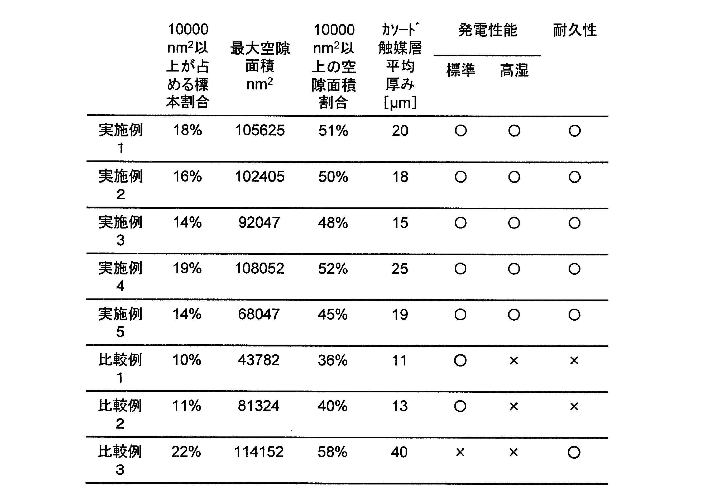
実施例1~5のいずれにおいても、10000nm2以上の空隙部の断面積の頻度が占める割合が13%以上20%以下の範囲に含まれることが認められた。
さらに、実施例3においては、空隙部の断面積の最大値が70000nm2以上100000nm2以下であり、空隙部が10000nm2以上である断面積の総和が、全空隙断面積(空隙部全ての断面積の総和)に対して40%以上50%以下を占めることが認められた。
その結果、実施例1~5のいずれにおいても、測定時の条件に関わらず発電性能が「○」であり、かつ、耐久性が「○」であることが認められた。すなわち、実施例1から実施例5の膜電極接合体は、発電性能および耐久性に優れた燃料電池を構成することが可能な膜電極接合体であることが認められた。
さらに、実施例3においては、空隙部の断面積の最大値が70000nm2以上100000nm2以下であり、空隙部が10000nm2以上である断面積の総和が、全空隙断面積(空隙部全ての断面積の総和)に対して40%以上50%以下を占めることが認められた。
その結果、実施例1~5のいずれにおいても、測定時の条件に関わらず発電性能が「○」であり、かつ、耐久性が「○」であることが認められた。すなわち、実施例1から実施例5の膜電極接合体は、発電性能および耐久性に優れた燃料電池を構成することが可能な膜電極接合体であることが認められた。
一方で10000nm2以上の空隙断面積の頻度が占める割合が13%以上20%以下の範囲に含まれない比較例1から比較例3では、標準条件および高湿条件のいずれかにおいて、発電性能が「×」であることが認められた。これは空隙断面積の分布が小面積側に偏ることで排水性および耐久性が低下すること、または大面積側に偏ることで活性点減少により性能が低下することによると推測される。
以上の結果により、本実施形態によれば、少なくとも触媒21と炭素粒子22と高分子電解質23と繊維状物質24とを含む触媒層構造の空隙断面積のヒストグラムにおいて10000nm2以上の空隙断面積の頻度が全頻度に占める割合が13%以上である膜電極接合体を用いることで、高い発電性能を発揮すると共にフラッディングを抑制し、耐久性を向上することができる。
つまり、ガス拡散性を向上させることで高出力化を実現し、且つ高い排水性も有することにより長期的な性能維持が可能な、固体高分子形燃料電池用触媒層、膜電極接合体、及び固体高分子形燃料電池を作成するためには、触媒層を構成する触媒21、炭素粒子22、高分子電解質23、及び繊維状物質24の各含有量をそれぞれ最適値に設定してもよいし、本実施形態で説明したように、「10000nm2以上の空隙部の断面積の頻度が占める割合」に着目し、その数値範囲を「13%以上20%以下」に設定してもよい。
つまり、ガス拡散性を向上させることで高出力化を実現し、且つ高い排水性も有することにより長期的な性能維持が可能な、固体高分子形燃料電池用触媒層、膜電極接合体、及び固体高分子形燃料電池を作成するためには、触媒層を構成する触媒21、炭素粒子22、高分子電解質23、及び繊維状物質24の各含有量をそれぞれ最適値に設定してもよいし、本実施形態で説明したように、「10000nm2以上の空隙部の断面積の頻度が占める割合」に着目し、その数値範囲を「13%以上20%以下」に設定してもよい。
本実施形態によれば、ガス拡散性を向上させることで高出力化を実現し、且つ高い排水性も有することにより長期的な性能維持が可能な触媒層、膜電極接合体および固体高分子形燃料電池を提供することができる。また、本実施形態は、上記固体高分子形燃料電池用触媒層または上記膜電極接合体を備えた単電池セル、燃料電池スタックを提供することもできる。したがって、本実施形態は、固体高分子形燃料電池を利用した、定置型コジェネレーションシステムや燃料電池自動車等に好適に用いることができ、産業上の利用価値が大きい。
1・・・高分子電解質膜
2・・・アノード触媒層(酸化極若しくは燃料極)
3・・・カソード触媒層(還元極若しくは空気極)
4・・・ガスケット
5・・・ガス拡散層
6・・・アノード
7・・・カソード
8・・・ガス流路
9・・・冷却水流路
10・・・セパレータ
11・・・固体高分子形燃料電池
12・・・膜電極接合体
21・・・触媒
22・・・炭素粒子
23・・・高分子電解質
24・・・繊維状物質
25・・・空隙
2・・・アノード触媒層(酸化極若しくは燃料極)
3・・・カソード触媒層(還元極若しくは空気極)
4・・・ガスケット
5・・・ガス拡散層
6・・・アノード
7・・・カソード
8・・・ガス流路
9・・・冷却水流路
10・・・セパレータ
11・・・固体高分子形燃料電池
12・・・膜電極接合体
21・・・触媒
22・・・炭素粒子
23・・・高分子電解質
24・・・繊維状物質
25・・・空隙
Claims (6)
- 触媒、炭素粒子、高分子電解質及び繊維状物質を含み、前記炭素粒子が前記触媒を担持している固体高分子形燃料電池用触媒層であって、
前記固体高分子形燃料電池用触媒層は、空隙部を有し、
前記触媒層の表面と直交する厚さ方向における断面において観察される前記空隙部のうち、10000nm2以上の断面積を有する前記空隙部の頻度が占める割合が13%以上20%以下であることを特徴とする触媒層。 - 前記空隙部の断面積の最大値が70000nm2以上100000nm2以下であることを特徴とする請求項1に記載の触媒層。
- 前記空隙部のうち断面積が10000nm2以上である前記空隙部の断面積の総和が、前記空隙部全ての断面積の総和に対して40%以上50%以下を占めること特徴とする請求項1または2に記載の触媒層。
- 前記触媒層の表面と直交する方向における前記触媒層の平均厚みが、1μm以上30μm以下の範囲内となるように構成されていることを特徴とする請求項1~3のいずれか一項に記載の触媒層。
- 高分子電解質膜の両面にアノード触媒層及びカソード触媒層を具備し、
前記アノード触媒層及び前記カソード触媒層の外周に額縁状のガスケットを具備し、
前記アノード触媒層若しくは前記カソード触媒層の少なくとも一方が、請求項1~4のいずれか一項に記載の固体高分子形燃料電池用触媒層であることを特徴とする膜電極接合体。 - 請求項1~4のいずれか一項に記載の触媒層または請求項5に記載の膜電極接合体を備えたことを特徴とする固体高分子形燃料電池。
Priority Applications (4)
| Application Number | Priority Date | Filing Date | Title |
|---|---|---|---|
| JP2021509397A JP7484888B2 (ja) | 2019-03-22 | 2020-03-23 | 固体高分子形燃料電池用触媒層、膜電極接合体、及び固体高分子形燃料電池 |
| EP20779726.7A EP3944383A4 (en) | 2019-03-22 | 2020-03-23 | CATALYST LAYER FOR SOLID POLYMER FUEL CELLS, DIAPHRAGM ELECTRODE ASSEMBLY AND SOLID POLYMER FUEL CELL |
| CN202080019922.0A CN113557618A (zh) | 2019-03-22 | 2020-03-23 | 固体高分子型燃料电池用催化剂层、膜电极接合体以及固体高分子型燃料电池 |
| US17/478,485 US12176547B2 (en) | 2019-03-22 | 2021-09-17 | Catalyst layer for polymer electrolyte fuel cells, membrane-electrode assembly, and polymer electrolyte fuel cell |
Applications Claiming Priority (2)
| Application Number | Priority Date | Filing Date | Title |
|---|---|---|---|
| JP2019-055655 | 2019-03-22 | ||
| JP2019055655 | 2019-03-22 |
Related Child Applications (1)
| Application Number | Title | Priority Date | Filing Date |
|---|---|---|---|
| US17/478,485 Continuation US12176547B2 (en) | 2019-03-22 | 2021-09-17 | Catalyst layer for polymer electrolyte fuel cells, membrane-electrode assembly, and polymer electrolyte fuel cell |
Publications (1)
| Publication Number | Publication Date |
|---|---|
| WO2020196419A1 true WO2020196419A1 (ja) | 2020-10-01 |
Family
ID=72608818
Family Applications (1)
| Application Number | Title | Priority Date | Filing Date |
|---|---|---|---|
| PCT/JP2020/012754 Ceased WO2020196419A1 (ja) | 2019-03-22 | 2020-03-23 | 固体高分子形燃料電池用触媒層、膜電極接合体、及び固体高分子形燃料電池 |
Country Status (5)
| Country | Link |
|---|---|
| US (1) | US12176547B2 (ja) |
| EP (1) | EP3944383A4 (ja) |
| JP (1) | JP7484888B2 (ja) |
| CN (1) | CN113557618A (ja) |
| WO (1) | WO2020196419A1 (ja) |
Cited By (1)
| Publication number | Priority date | Publication date | Assignee | Title |
|---|---|---|---|---|
| JP2023161086A (ja) * | 2022-04-25 | 2023-11-07 | トヨタ自動車株式会社 | 触媒層 |
Citations (6)
| Publication number | Priority date | Publication date | Assignee | Title |
|---|---|---|---|---|
| US5728485A (en) * | 1995-03-15 | 1998-03-17 | Tanaka Kikinzoku Kogyo K.K. | Electrode for polymer electrolyte electrochemical cell and process of preparing same |
| JP2005190872A (ja) * | 2003-12-26 | 2005-07-14 | Toyota Motor Corp | 燃料電池用触媒組成物、膜電極接合体及び固体高分子形燃料電池 |
| JP2009238556A (ja) * | 2008-03-27 | 2009-10-15 | Dainippon Printing Co Ltd | 固体高分子形燃料電池用触媒層 |
| JP2016207419A (ja) * | 2015-04-21 | 2016-12-08 | 凸版印刷株式会社 | 電極触媒層、膜電極接合体および固体高分子形燃料電池 |
| JP2017069056A (ja) * | 2015-09-30 | 2017-04-06 | 凸版印刷株式会社 | 電極触媒層、膜電極接合体および固体高分子形燃料電池 |
| WO2019189839A1 (ja) * | 2018-03-30 | 2019-10-03 | 凸版印刷株式会社 | 膜電極接合体、および、固体高分子形燃料電池 |
Family Cites Families (15)
| Publication number | Priority date | Publication date | Assignee | Title |
|---|---|---|---|---|
| JP3617237B2 (ja) | 1997-02-21 | 2005-02-02 | トヨタ自動車株式会社 | 燃料電池用の電極および発電層並びにその製造方法 |
| JP4037814B2 (ja) | 2003-09-26 | 2008-01-23 | 株式会社東芝 | 燃料電池用膜−電極接合体及び燃料電池 |
| JP3981684B2 (ja) * | 2003-11-26 | 2007-09-26 | 日立マクセル株式会社 | 液体燃料電池用発電素子およびその製造方法、並びにそれを用いた液体燃料電池 |
| JP4031463B2 (ja) * | 2004-04-26 | 2008-01-09 | 株式会社東芝 | 液体燃料型固体高分子燃料電池用アノード電極、液体燃料型固体高分子燃料電池用膜電極複合体及び液体燃料型固体高分子燃料電池 |
| US20060166074A1 (en) * | 2005-01-26 | 2006-07-27 | Pan Alfred I | Fuel cell electrode assembly |
| CN101297425A (zh) * | 2005-10-31 | 2008-10-29 | 旭硝子株式会社 | 固体高分子型燃料电池用膜电极接合体的制造方法 |
| JP2007200762A (ja) * | 2006-01-27 | 2007-08-09 | Asahi Glass Co Ltd | 固体高分子形燃料電池用膜電極接合体およびその製造方法 |
| JP5219350B2 (ja) * | 2006-08-22 | 2013-06-26 | 大日本印刷株式会社 | 固体高分子型燃料電池用の触媒層及びその製造方法 |
| CN101617424B (zh) * | 2007-02-02 | 2012-11-28 | 旭硝子株式会社 | 固体高分子型燃料电池用膜电极接合体的制造方法及固体高分子型燃料电池的制造方法 |
| JP5233153B2 (ja) * | 2007-04-06 | 2013-07-10 | 旭硝子株式会社 | 固体高分子形燃料電池用膜電極接合体 |
| CN100557874C (zh) * | 2007-06-06 | 2009-11-04 | 武汉理工大学 | 聚合物超短纤维作为疏水剂的燃料电池膜电极及其制备方法 |
| JP5266794B2 (ja) * | 2008-03-03 | 2013-08-21 | 大日本印刷株式会社 | 固体高分子形燃料電池用触媒層及びその製造方法 |
| JP5810860B2 (ja) * | 2011-11-17 | 2015-11-11 | 日産自動車株式会社 | 燃料電池用電極触媒層 |
| WO2015135069A1 (en) * | 2014-03-11 | 2015-09-17 | Uti Limited Partnership | Porous carbon films |
| JP6432703B1 (ja) * | 2018-01-31 | 2018-12-05 | 凸版印刷株式会社 | 固体高分子形燃料電池用膜電極接合体、固体高分子形燃料電池及び固体高分子形燃料電池用膜電極接合体の製造方法 |
-
2020
- 2020-03-23 WO PCT/JP2020/012754 patent/WO2020196419A1/ja not_active Ceased
- 2020-03-23 JP JP2021509397A patent/JP7484888B2/ja active Active
- 2020-03-23 EP EP20779726.7A patent/EP3944383A4/en active Pending
- 2020-03-23 CN CN202080019922.0A patent/CN113557618A/zh active Pending
-
2021
- 2021-09-17 US US17/478,485 patent/US12176547B2/en active Active
Patent Citations (6)
| Publication number | Priority date | Publication date | Assignee | Title |
|---|---|---|---|---|
| US5728485A (en) * | 1995-03-15 | 1998-03-17 | Tanaka Kikinzoku Kogyo K.K. | Electrode for polymer electrolyte electrochemical cell and process of preparing same |
| JP2005190872A (ja) * | 2003-12-26 | 2005-07-14 | Toyota Motor Corp | 燃料電池用触媒組成物、膜電極接合体及び固体高分子形燃料電池 |
| JP2009238556A (ja) * | 2008-03-27 | 2009-10-15 | Dainippon Printing Co Ltd | 固体高分子形燃料電池用触媒層 |
| JP2016207419A (ja) * | 2015-04-21 | 2016-12-08 | 凸版印刷株式会社 | 電極触媒層、膜電極接合体および固体高分子形燃料電池 |
| JP2017069056A (ja) * | 2015-09-30 | 2017-04-06 | 凸版印刷株式会社 | 電極触媒層、膜電極接合体および固体高分子形燃料電池 |
| WO2019189839A1 (ja) * | 2018-03-30 | 2019-10-03 | 凸版印刷株式会社 | 膜電極接合体、および、固体高分子形燃料電池 |
Non-Patent Citations (1)
| Title |
|---|
| See also references of EP3944383A4 * |
Cited By (2)
| Publication number | Priority date | Publication date | Assignee | Title |
|---|---|---|---|---|
| JP2023161086A (ja) * | 2022-04-25 | 2023-11-07 | トヨタ自動車株式会社 | 触媒層 |
| JP7831114B2 (ja) | 2022-04-25 | 2026-03-17 | トヨタ自動車株式会社 | 触媒層 |
Also Published As
| Publication number | Publication date |
|---|---|
| US20220006099A1 (en) | 2022-01-06 |
| US12176547B2 (en) | 2024-12-24 |
| CN113557618A (zh) | 2021-10-26 |
| JPWO2020196419A1 (ja) | 2020-10-01 |
| EP3944383A4 (en) | 2022-05-18 |
| EP3944383A1 (en) | 2022-01-26 |
| JP7484888B2 (ja) | 2024-05-16 |
Similar Documents
| Publication | Publication Date | Title |
|---|---|---|
| JP7544203B2 (ja) | 電極触媒層、膜電極接合体及び固体高分子形燃料電池 | |
| JP7452480B2 (ja) | 触媒層及びその製造方法 | |
| JP6332541B1 (ja) | 電極触媒層 | |
| JP7363976B2 (ja) | 電極触媒層、膜電極接合体及び固体高分子形燃料電池 | |
| JP2008204664A (ja) | 燃料電池用膜電極接合体、およびこれを用いた燃料電池 | |
| WO2022124407A1 (ja) | 電極触媒層、膜電極接合体及び固体高分子形燃料電池 | |
| CN111247677B (zh) | 电极催化剂层及固体高分子型燃料电池 | |
| JP2020057516A (ja) | 電極層ならびに当該電極層を用いた膜電極接合体および燃料電池 | |
| JP7225691B2 (ja) | 膜電極接合体及び固体高分子形燃料電池 | |
| JP7484888B2 (ja) | 固体高分子形燃料電池用触媒層、膜電極接合体、及び固体高分子形燃料電池 | |
| JP7294513B2 (ja) | 電極触媒層及び固体高分子形燃料電池 | |
| US11990625B2 (en) | Electrode catalyst layer, membrane electrode assembly, and polymer electrolyte fuel cell | |
| JP7067136B2 (ja) | 触媒層、膜電極接合体、固体高分子形燃料電池 | |
| JP7243208B2 (ja) | 電極触媒層、膜電極接合体、および、固体高分子形燃料電池 | |
| JP7119402B2 (ja) | 膜電極接合体およびこれを備えた固体高分子形燃料電池 | |
| JP6950617B2 (ja) | 電極触媒層 | |
| WO2020138433A1 (ja) | 電極触媒層、膜電極接合体、および、固体高分子形燃料電池 | |
| JP7363266B2 (ja) | カソード側電極触媒層、膜電極接合体、および、固体高分子形燃料電池 | |
| JP7726354B1 (ja) | 膜電極接合体および燃料電池 | |
| JP7140256B2 (ja) | 電極触媒層 | |
| JP7831114B2 (ja) | 触媒層 | |
| JP7293832B2 (ja) | 電極触媒層、膜電極接合体、および、固体高分子形燃料電池 | |
| JP2022168133A (ja) | 電極触媒層、膜電極接合体及び固体高分子形燃料電池 |
Legal Events
| Date | Code | Title | Description |
|---|---|---|---|
| 121 | Ep: the epo has been informed by wipo that ep was designated in this application |
Ref document number: 20779726 Country of ref document: EP Kind code of ref document: A1 |
|
| ENP | Entry into the national phase |
Ref document number: 2021509397 Country of ref document: JP Kind code of ref document: A |
|
| NENP | Non-entry into the national phase |
Ref country code: DE |
|
| WWE | Wipo information: entry into national phase |
Ref document number: 2020779726 Country of ref document: EP |