WO2020196428A1 - Vibreur à ultrasons - Google Patents
Vibreur à ultrasons Download PDFInfo
- Publication number
- WO2020196428A1 WO2020196428A1 PCT/JP2020/012778 JP2020012778W WO2020196428A1 WO 2020196428 A1 WO2020196428 A1 WO 2020196428A1 JP 2020012778 W JP2020012778 W JP 2020012778W WO 2020196428 A1 WO2020196428 A1 WO 2020196428A1
- Authority
- WO
- WIPO (PCT)
- Prior art keywords
- piezoelectric element
- terminal
- electrode
- thickness direction
- main body
- Prior art date
- Legal status (The legal status is an assumption and is not a legal conclusion. Google has not performed a legal analysis and makes no representation as to the accuracy of the status listed.)
- Ceased
Links
Images


Classifications
-
- B—PERFORMING OPERATIONS; TRANSPORTING
- B06—GENERATING OR TRANSMITTING MECHANICAL VIBRATIONS IN GENERAL
- B06B—METHODS OR APPARATUS FOR GENERATING OR TRANSMITTING MECHANICAL VIBRATIONS OF INFRASONIC, SONIC, OR ULTRASONIC FREQUENCY, e.g. FOR PERFORMING MECHANICAL WORK IN GENERAL
- B06B1/00—Methods or apparatus for generating mechanical vibrations of infrasonic, sonic, or ultrasonic frequency
- B06B1/02—Methods or apparatus for generating mechanical vibrations of infrasonic, sonic, or ultrasonic frequency making use of electrical energy
- B06B1/06—Methods or apparatus for generating mechanical vibrations of infrasonic, sonic, or ultrasonic frequency making use of electrical energy operating with piezoelectric effect or with electrostriction
- B06B1/0644—Methods or apparatus for generating mechanical vibrations of infrasonic, sonic, or ultrasonic frequency making use of electrical energy operating with piezoelectric effect or with electrostriction using a single piezoelectric element
- B06B1/0648—Methods or apparatus for generating mechanical vibrations of infrasonic, sonic, or ultrasonic frequency making use of electrical energy operating with piezoelectric effect or with electrostriction using a single piezoelectric element of rectangular shape
-
- A—HUMAN NECESSITIES
- A61—MEDICAL OR VETERINARY SCIENCE; HYGIENE
- A61B—DIAGNOSIS; SURGERY; IDENTIFICATION
- A61B8/00—Diagnosis using ultrasonic, sonic or infrasonic waves
- A61B8/44—Constructional features of the ultrasonic, sonic or infrasonic diagnostic device
- A61B8/4483—Constructional features of the ultrasonic, sonic or infrasonic diagnostic device characterised by features of the ultrasound transducer
- A61B8/4494—Constructional features of the ultrasonic, sonic or infrasonic diagnostic device characterised by features of the ultrasound transducer characterised by the arrangement of the transducer elements
-
- A—HUMAN NECESSITIES
- A61—MEDICAL OR VETERINARY SCIENCE; HYGIENE
- A61B—DIAGNOSIS; SURGERY; IDENTIFICATION
- A61B8/00—Diagnosis using ultrasonic, sonic or infrasonic waves
- A61B8/12—Diagnosis using ultrasonic, sonic or infrasonic waves in body cavities or body tracts, e.g. by using catheters
-
- A—HUMAN NECESSITIES
- A61—MEDICAL OR VETERINARY SCIENCE; HYGIENE
- A61B—DIAGNOSIS; SURGERY; IDENTIFICATION
- A61B8/00—Diagnosis using ultrasonic, sonic or infrasonic waves
- A61B8/44—Constructional features of the ultrasonic, sonic or infrasonic diagnostic device
- A61B8/4444—Constructional features of the ultrasonic, sonic or infrasonic diagnostic device related to the probe
- A61B8/445—Details of catheter construction
-
- B—PERFORMING OPERATIONS; TRANSPORTING
- B06—GENERATING OR TRANSMITTING MECHANICAL VIBRATIONS IN GENERAL
- B06B—METHODS OR APPARATUS FOR GENERATING OR TRANSMITTING MECHANICAL VIBRATIONS OF INFRASONIC, SONIC, OR ULTRASONIC FREQUENCY, e.g. FOR PERFORMING MECHANICAL WORK IN GENERAL
- B06B1/00—Methods or apparatus for generating mechanical vibrations of infrasonic, sonic, or ultrasonic frequency
- B06B1/02—Methods or apparatus for generating mechanical vibrations of infrasonic, sonic, or ultrasonic frequency making use of electrical energy
- B06B1/06—Methods or apparatus for generating mechanical vibrations of infrasonic, sonic, or ultrasonic frequency making use of electrical energy operating with piezoelectric effect or with electrostriction
- B06B1/0644—Methods or apparatus for generating mechanical vibrations of infrasonic, sonic, or ultrasonic frequency making use of electrical energy operating with piezoelectric effect or with electrostriction using a single piezoelectric element
- B06B1/0662—Methods or apparatus for generating mechanical vibrations of infrasonic, sonic, or ultrasonic frequency making use of electrical energy operating with piezoelectric effect or with electrostriction using a single piezoelectric element with an electrode on the sensitive surface
- B06B1/067—Methods or apparatus for generating mechanical vibrations of infrasonic, sonic, or ultrasonic frequency making use of electrical energy operating with piezoelectric effect or with electrostriction using a single piezoelectric element with an electrode on the sensitive surface which is used as, or combined with, an impedance matching layer
-
- B—PERFORMING OPERATIONS; TRANSPORTING
- B06—GENERATING OR TRANSMITTING MECHANICAL VIBRATIONS IN GENERAL
- B06B—METHODS OR APPARATUS FOR GENERATING OR TRANSMITTING MECHANICAL VIBRATIONS OF INFRASONIC, SONIC, OR ULTRASONIC FREQUENCY, e.g. FOR PERFORMING MECHANICAL WORK IN GENERAL
- B06B2201/00—Indexing scheme associated with B06B1/0207 for details covered by B06B1/0207 but not provided for in any of its subgroups
- B06B2201/70—Specific application
- B06B2201/76—Medical, dental
Definitions
- This disclosure relates to an ultrasonic transducer.
- An ultrasonic probe including an ultrasonic transducer is used as an ultrasonic transmitter / receiver for a medical ultrasonic diagnostic device. Recently, an ultrasonic probe is loaded into a catheter, and an ultrasonic diagnosis is performed with the catheter inserted in the body.
- Patent Document 1 describes an active transducer element having a top main surface and a bottom main surface, a top electrode formed on the top main surface, a bottom electrode formed on the bottom main surface, and conductivity covering the bottom electrode.
- An ultrasonic probe comprising a backing element, a first lead electrically connected to a top electrode, and a second lead electrically connected to a conductive backing element is disclosed.
- the miniaturization of the ultrasonic probe can be realized by miniaturizing the ultrasonic vibrator including the piezoelectric element and the piezoelectric element composed of a pair of electrodes.
- the piezoelectric element is also miniaturized. Therefore, the electrode of the piezoelectric element also becomes small, and it becomes difficult to connect the electric signal line connecting the piezoelectric element and the external power source to the electrode of the piezoelectric element.
- An object of the present disclosure is to provide an ultrasonic oscillator having a configuration that facilitates connection of an electric signal line to a piezoelectric element.
- the ultrasonic vibrator as the first aspect of the present disclosure is an ultrasonic vibrator including a piezoelectric element and a support member for supporting the piezoelectric element, and the piezoelectric element is a flat piezoelectric body.
- the support member comprises a first electrode laminated on at least one side in the thickness direction of the piezoelectric body and a second electrode laminated on at least the other side in the thickness direction of the piezoelectric body.
- a first terminal connected to the first electrode of the piezoelectric element and a second terminal connected to the second electrode of the piezoelectric element are provided, and the first terminal and the second terminal are A portion that does not overlap with the piezoelectric element in the thickness direction is provided.
- the support member is laminated on the piezoelectric element on the other side in the thickness direction, and extends to the outside of the piezoelectric element in a direction orthogonal to the thickness direction.
- a main body is provided, and the first terminal and the second terminal are supported by the support main body.
- the first electrode of the piezoelectric element is located on a surface electrode layer located on the one side of the piezoelectric body in the thickness direction and on the other side of the piezoelectric body in the thickness direction. It includes a back surface electrode layer located, and a connecting conductive portion that connects the front surface electrode layer and the back surface electrode layer.
- the first terminal is connected to the back surface electrode layer of the first electrode between the piezoelectric element and the support main body portion.
- the second terminal is connected to the second electrode between the piezoelectric element and the support main body portion.
- the piezoelectric element includes a first portion composed of a portion overlapping the first terminal and a portion overlapping the second terminal in the thickness direction, and a second portion excluding the first portion. , And the entire area of the second portion on the other side in the thickness direction is covered with the support main body portion.
- an ultrasonic oscillator having a configuration that facilitates connection of an electric signal line to a piezoelectric element.
- FIG. 1 is a diagram showing an image diagnostic apparatus 100 including an ultrasonic oscillator 11 as an embodiment.
- the diagnostic imaging device 100 includes a diagnostic imaging catheter 110 and an external device 120.
- FIG. 1 shows a state in which the diagnostic imaging catheter 110 is connected to the external device 120.
- FIG. 2 is a cross-sectional view showing a cross section parallel to the longitudinal direction A at the tip of the diagnostic imaging catheter 110.
- FIG. 3 is a diagram showing an ultrasonic transducer 11. In FIG. 3, for convenience of explanation, the position of the electric signal line 14 connected to the ultrasonic vibrator 11 is shown by a chain double-dashed line.
- FIG. 4 is a diagram showing the back surface of the piezoelectric element 1 in the ultrasonic oscillator 11 shown in FIG.
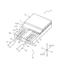
- FIG. 5 is an exploded perspective view of the ultrasonic vibrator 11 shown in FIG. Also in FIG.
- FIG. 5 is a diagram showing a region where the piezoelectric element 1 and the support member 2 overlap in the thickness direction B in the ultrasonic vibrator 11 shown in FIG.
- the diagnostic imaging catheter 110 is applied to an intravascular ultrasound (abbreviated as "IVUS"). As shown in FIG. 1, the diagnostic imaging catheter 110 is driven by being connected to an external device 120. More specifically, the diagnostic imaging catheter 110 of the present embodiment is connected to the drive unit 120a of the external device 120.
- IVUS intravascular ultrasound
- the side inserted into the living body in the longitudinal direction A of the diagnostic imaging catheter 110 is described as the "tip side", and the opposite side is described as the "base end side”. To do. Further, the direction from the proximal end side to the distal end side of the diagnostic imaging catheter 110 may be simply described as "insertion direction A1". Further, the direction from the distal end side to the proximal end side of the diagnostic imaging catheter 110 may be simply described as "removal direction A2".
- the diagnostic imaging catheter 110 includes an insertion portion 110a and an operation portion 110b.
- the insertion portion 110a is a portion of the diagnostic imaging catheter 110 that is inserted into the living body and used.
- the operation unit 110b is a portion of the diagnostic imaging catheter 110 that is operated in vitro with the insertion unit 110a inserted into the living body.
- the portion on the distal end side of the distal end side connector 42 (see FIG. 1) described later is the insertion portion 110a
- the portion on the proximal end side from the distal end side connector 42 is the operation portion 110b. is there.
- the insertion portion 110a includes an ultrasonic probe 10 and a sheath 20.
- the operation unit 110b includes an inner pipe member 30 and an outer pipe member 40.
- the inner tube member 30 holds an end portion of the ultrasonic probe 10 on the proximal end side.
- the outer tube member 40 holds an end portion of the sheath 20 on the base end side.
- the ultrasonic probe 10 can move in the sheath 20 in the longitudinal direction A by moving the inner tube member 30 in the outer tube member 40 in the central axis direction.
- the drive shaft 13 and the electric signal line 14 which are a part of the ultrasonic probe 10 pass through the inside of the inner tube member 30 and the outer tube member 40, and the insertion portion 110a is inserted in the longitudinal direction A. It extends not only to the region of the above but also to the region of the operation unit 110b. That is, the operation unit 110b of the present embodiment is partially composed of the ultrasonic probe 10 in addition to the inner tube member 30 and the outer tube member 40.
- the ultrasonic probe 10 includes an ultrasonic oscillator 11, a housing 12, a drive shaft 13, and an electric signal line 14.
- the ultrasonic vibrator 11 includes a piezoelectric element 1, a support member 2, and an acoustic matching member 3.
- the piezoelectric element 1 includes a flat piezoelectric body 4, a first electrode 5 laminated on at least one side of the piezoelectric body 4 in the thickness direction B, and at least the other of the piezoelectric body 4 in the thickness direction B. It is composed of a second electrode 6 laminated on the side.
- the surface side of the piezoelectric element 1 one side of the thickness direction B of the piezoelectric body 4 in which at least a part of the first electrode 5 is provided.
- the other side of the piezoelectric body 4 in the thickness direction B in which at least a part of the second electrode 6 is provided is described as "the back surface side of the piezoelectric element 1".
- the surface side of the piezoelectric element 1 is a side that transmits and receives ultrasonic waves. Further, the back surface side of the piezoelectric element 1 is the side opposite to the side that transmits and receives ultrasonic waves.
- the piezoelectric body 4 of the piezoelectric element 1 is composed of, for example, a piezoelectric ceramic sheet.
- Examples of the material of the piezoelectric ceramic sheet include piezoelectric ceramic materials such as lead titanate (PZT) and lithium niobate.
- the piezoelectric body 4 may be made of crystal instead of the piezoelectric ceramic material.
- the first electrode 5 and the second electrode 6 of the piezoelectric element 1 are laminated as electrode layers on both sides of the piezoelectric body 4 in the thickness direction B by, for example, an ion plating method using a mask material, a vapor deposition method, or a sputtering method.
- an ion plating method using a mask material e.g., aluminum, copper, nickel, and gold.
- the material of the first electrode 5 and the second electrode 6 include metals such as silver, chromium, copper, nickel, and gold, and laminates of these metals.
- the second electrode 6 of the present embodiment is formed only on the back surface side of the piezoelectric element 1.
- the first electrode 5 of the present embodiment is composed of a folded electrode.
- the first electrode 5 of the present embodiment includes a front electrode layer 5a, a back electrode layer 5b, and a connecting conductive portion 5c.
- the surface electrode layer 5a is located on the surface side of the piezoelectric element 1.
- the back surface electrode layer 5b is located on the back surface side of the piezoelectric element 1.
- the connecting conductive portion 5c connects the front surface electrode layer 5a and the back surface electrode layer 5b.
- the first electrode 5 of the present embodiment is formed from the front surface side to the back surface side of the piezoelectric element 1.
- the back electrode layer 5b of the first electrode 5 and the second electrode 6 can be arranged together on the back surface side of the piezoelectric element 1.
- the connection work between the electric signal line 14, the first electrode 5, and the second electrode 6 is performed in a piezoelectric manner, as compared with the case where the first electrode and the second electrode are arranged only on separate surfaces of the piezoelectric element. This can be done only on one side of the element 1.
- the piezoelectric element 1 has a thickness direction B, a first portion 1a composed of a portion overlapping the first terminal 7 and a portion overlapping the second terminal 8 of the support member 2 described later, and a thickness direction.
- B includes a second portion 1b excluding the first portion 1a. The details will be described later.
- the outer shape of the piezoelectric element 1 is preferably square as in the present embodiment rather than rectangular. .. By doing so, the straightness of the ultrasonic wave can be improved. Therefore, as shown in FIG. 6, it is preferable that the lengths (vertical direction in FIG. 6) and horizontal (horizontal direction in FIG. 6) of the piezoelectric element 1 are substantially equal. Further, in the case of a small ultrasonic transducer 11 used in a blood vessel, it is preferable to increase the output of ultrasonic waves.
- the piezoelectric element 1 has a square outer shape in a plan view shown in FIG. 6, and the area of the second portion 1b of the piezoelectric element 1 is larger than the area of the first portion 1a of the piezoelectric element 1. Is preferable.
- the support member 2 supports the piezoelectric element 1. Further, as shown in FIGS. 3 and 5, the support member 2 is connected to the first terminal 7 connected to the first electrode 5 of the piezoelectric element 1 and the second electrode 6 of the piezoelectric element 1. It includes two terminals 8. Further, as shown in FIG. 3, the first terminal 7 and the second terminal 8 include a portion that does not overlap with the piezoelectric element 1 in the thickness direction B. By providing such a first terminal 7 and a second terminal 8, the electrical contact point between the first electrode 5 and the second electrode 6 of the piezoelectric element 1 can be pulled out to the outside of the piezoelectric element 1.
- the support member 2 of the present embodiment supports the piezoelectric element 1 from the back surface side of the piezoelectric element 1.
- the support member 2 is laminated on the back surface side of the piezoelectric element 1 so as to cover the back surface side of the piezoelectric element 1.
- Examples of the material of the first terminal 7 and the second terminal 8 include metals such as silver, chromium, copper, nickel, and gold, and laminates of these metals.
- the support member 2 of the present embodiment includes a support main body 9 laminated on the back surface side of the piezoelectric element 1.
- the support main body 9 covers at least the entire back surface side of the piezoelectric body 4 of the piezoelectric element 1.
- the support main body 9 of the present embodiment covers the entire area on the back surface side of the piezoelectric element 1. More specifically, the support main body 9 of the present embodiment extends to the outside of the piezoelectric element 1 in the direction C (hereinafter, referred to as "in-plane direction C") orthogonal to the thickness direction B of the piezoelectric element 1. Exists.
- the first terminal 7 and the second terminal 8 of the present embodiment are supported by the support main body portion 9.
- the support main body 9 of the support member 2 is a sound absorber composed of, for example, rubber or an epoxy resin in which a metal powder such as tungsten powder is dispersed.
- the support main body 9 of the support member 2 can absorb the ultrasonic waves from the piezoelectric element 1 that become noise. That is, the support member 2 of the present embodiment constitutes a sound absorbing layer that absorbs the ultrasonic waves of the piezoelectric element 1.
- a method in which the first terminal 7 and the second terminal 8 are arranged in advance on the sheet material forming the support main body portion 9 and the sheet material is bonded to the piezoelectric element 1 or the like. Can be formed by.
- the first terminal 7 and the second terminal 8 may be formed by laminating the sheet material forming the support main body 9 by, for example, an ion plating method using a mask material, a vapor deposition method, or a sputtering method.
- the manufacturing method is not particularly limited.
- the terminal members forming the first terminal 7 and the second terminal 8 may be bonded to the support main body 9 by adhesion or the like.
- the first terminal 7 of the present embodiment is connected between the piezoelectric element 1 and the support main body 9 to the back surface electrode layer 5b of the first electrode 5.
- the piezoelectric element 1 and the support member 2 of the present embodiment are laminated so that the back electrode layer 5b of the first electrode 5 and the first terminal 7 face each other.
- the first terminal 7 of the present embodiment extends from the position between the piezoelectric element 1 and the support main body 9 to the outside of the piezoelectric element 1 in the in-plane direction C.
- the first terminal 7 is a piezoelectric element in the thickness direction B on the surface of the support main body 9 on the piezoelectric element 1 side in the thickness direction B (hereinafter, referred to as “upper surface of the support main body 9”). It is pulled out to a position that does not overlap with 1.
- the second terminal 8 of the present embodiment is connected to the second electrode 6 between the piezoelectric element 1 and the support main body portion 9.
- the piezoelectric element 1 and the support member 2 of the present embodiment are laminated so that the second electrode 6 and the second terminal 8 face each other.
- the second terminal 8 of the present embodiment extends from the position between the piezoelectric element 1 and the support main body 9 to the outside of the piezoelectric element 1 in the in-plane direction C. In other words, the second terminal 8 is pulled out on the upper surface of the support main body 9 to a position where it does not overlap with the piezoelectric element 1 in the thickness direction B.
- the first electrode 5 and the second electrode 6 of the piezoelectric element 1 are connected to the first terminal 7 and the second terminal 8 of the support member 2 on the back surface side of the piezoelectric element 1. Therefore, it is not necessary to secure a connection point of the electric signal line 14 on the surface side of the piezoelectric element 1 that transmits and receives ultrasonic waves, and when the electric signal line 14 is connected, the ultrasonic waves of the ultrasonic vibrator 11 are transmitted and received. It is possible to prevent the portion of the piezoelectric element 1 on the surface side from being damaged.
- the first terminal 7 and the second terminal 8 are visible from the surface side of the piezoelectric element 1. Therefore, the work of connecting the electric signal line 14 to the first terminal 7 and the second terminal 8 can be executed while visually monitoring the connection points and the like. As a result, it is possible to suppress the occurrence of defective products due to poor connection.
- the first terminal 7 and the second terminal 8 of the present embodiment are pulled out from a position overlapping the piezoelectric element 1 in the thickness direction B toward the proximal end side in the longitudinal direction A in the diagnostic imaging catheter 110. .. Therefore, of the first terminal 7 and the second terminal 8 of the present embodiment, the portion that does not overlap with the piezoelectric element 1 in the thickness direction B is provided on the proximal end side with respect to the piezoelectric element 1. As a result, as shown in FIG. 2, the first terminal 7 and the second terminal 8 of the present embodiment can easily be formed with the tip portion 14a of the electric signal line 14 extending from the tip end of the drive shaft 13 into the housing 12. You can connect.
- the first terminal 7 and the second terminal 8 of the present embodiment extend to the peripheral edge of the support member 2 in the in-plane direction C. More specifically, the first terminal 7 and the second terminal 8 of the present embodiment extend to a position where they are flush with the end surface of the support main body 9 in the in-plane direction C. By doing so, the electric signal line 14 can be more easily connected to the first terminal 7 and the second terminal 8 from the outside of the ultrasonic transducer 11.
- two groove portions 9a are partitioned on the upper surface of the support main body portion 9 facing the back surface of the piezoelectric element 1.
- the cross section of the groove portion 9a of the present embodiment is rectangular, but it may have another cross section shape such as a V shape or an arc shape.
- the first terminal 7 and the second terminal 8 of the present embodiment are arranged in the groove portion 9a of the support main body portion 9. Further, the upper surface of the first terminal 7 and the upper surface of the second terminal 8 facing the back surface of the piezoelectric element 1 are arranged so as to be flush with the upper surface of the support main body 9.
- the first electrode 5 and the second electrode 6 of the piezoelectric element 1 and the first terminal 7 and the second terminal 8 of the support member 2 are brought into contact with each other.
- the position stability of the piezoelectric element 1 on the support member 2 can be improved.
- the first electrode 5 and the second electrode 6 of the piezoelectric element 1 and the first terminal 7 and the second terminal 8 of the support member 2 are connected by using a conductive adhesive or the like.
- the upper surface of the first terminal 7 and the upper surface of the second terminal 8 facing the back surface of the piezoelectric element 1 may not protrude from the upper surface of the support main body portion 9 and may be arranged in the groove portion 9a.
- a conductive material such as the above-mentioned conductive adhesive is placed between the first electrode 5 and the second electrode 6 of the piezoelectric element 1 and the first terminal 7 and the second terminal 8 of the support member 2. It may be filled with.
- the first terminal 7 of the present embodiment partitions the groove portion 7a accommodating the electric signal line 14. Since the first terminal 7 partitions such a groove portion 7a, the electric signal line 14 can be connected to the first terminal 7 in a state where the electric signal line 14 is positioned in the groove portion 7a. Therefore, the efficiency of the connection work between the electric signal line 14 and the first terminal 7 is improved.
- the second terminal 8 of the present embodiment also has a groove portion 8a for accommodating the electric signal line 14.
- the electric signal line 14 can be connected to the second terminal 8 in a state where the electric signal line 14 is positioned in the groove 8a. Therefore, the efficiency of the connection work between the electric signal line 14 and the second terminal 8 is improved.
- the electric signal line 14 can be connected to each terminal (first terminal 7, second terminal in this embodiment). It becomes easy to connect to 8).
- the cross-sectional shape of the groove portion 7a and the groove portion 8a of the present embodiment is rectangular, but a groove portion having a cross-sectional shape such as a V-shape or an arc shape may be used. Further, it is preferable that the groove portion 7a and the groove portion 8a also extend to a position where they are flush with the end surface of the support main body portion 9 in the in-plane direction C. By doing so, it becomes easier to position the electric signal line 14.
- FIG. 7 is a diagram showing an outline of a process of connecting the electric signal line 14 to the first terminal 7.
- a connecting portion 14a made of a conducting wire from which the covering material has been removed is formed at the end of the electric signal wire 14.
- the groove portion 7a of the first terminal 7 is filled with the solder paste 205.
- the groove portion 7a may be filled with preliminary solder.
- the connecting portion 14a of the electric signal line 14 is arranged on the solder paste 205 filled in the groove portion 7a of the first terminal 7. It may be buried in the solder paste 205 filled in the groove 7a.
- Preliminary solder or solder paste may be further applied so as to sandwich the connection portion 14a with the solder paste 205.
- the solder paste 205 and the preliminary solder are melted by heating with hot air, and the connecting portion 14a is connected to the first terminal 7 in the groove portion 7a. In this way, the electric signal line 14 can be connected to the first terminal 7.
- connection method between the electric signal line 14 and the first terminal 7 is shown, but the same applies to the connection method between the electric signal line 14 and the second terminal 8.
- the piezoelectric element 1 includes a first portion 1a composed of a portion overlapping the first terminal 7 and a portion overlapping the second terminal 8 in the thickness direction B, and a second portion 1b excluding the first portion 1a. , (See FIG. 6).
- the entire area on the back surface side of the second portion 1b of the piezoelectric element 1 is covered with the support main body portion 9.
- the support main body portion 9 is arranged over the entire back surface of the second portion 1b, which is a mainly vibrating portion of the piezoelectric element 1. Therefore, the ultrasonic wave from the piezoelectric element 1 which becomes noise can be more reliably absorbed by the support main body portion 9.
- the acoustic matching member 3 is laminated so as to cover a part of the surface side of the piezoelectric element 1. More specifically, the acoustic matching member 3 of the present embodiment is laminated so as to cover most of the surface side (for example, 80% or more) of the second portion 1b of the piezoelectric element 1, but the present invention is not limited to this configuration. , The second portion 1b of the piezoelectric element 1 may be laminated so as to cover the entire surface side. Further, the piezoelectric element 1 may be laminated so as to cover the surface side of both the first portion 1a and the second portion 1b, or may be laminated so as to cover the entire surface side of the piezoelectric element 1.
- the acoustic matching member 3 of the present embodiment constitutes an acoustic matching layer that enhances the propagation efficiency of ultrasonic waves.
- the acoustic matching layer as the acoustic matching member 3 is formed by a method in which a sheet material forming the acoustic matching layer is attached to the piezoelectric element 1, a method in which a liquid acoustic matching material forming the acoustic matching layer is applied and cured, and the like. Can be formed.
- the material of the acoustic matching member 3 include a resin material such as an epoxy resin.
- the acoustic matching member 3 may be composed of a laminate of resin layers made of a resin material.
- the housing 12 houses the ultrasonic oscillator 11 inside.
- the base end side of the housing 12 is connected to the drive shaft 13.
- the housing 12 has a shape in which an opening 12a is provided in a part of the peripheral wall of a cylindrical metal pipe in which both ends in the axial direction are closed, and is machined from a metal block or MIM (metal powder injection). It is formed by molding) or the like.
- the housing 12 of the present embodiment includes a tip wall portion 12b located on the tip side of the above-mentioned opening 12a and a base end wall portion 12c located on the base end side of the above-mentioned opening 12a. , Equipped with.
- both ends in the axial direction are closed by the tip wall portion 12b and the base end wall portion 12c.
- the drive shaft 13 is made of a flexible tubular body. Inside the drive shaft 13, an electric signal line 14 connected to the ultrasonic transducer 11 is arranged.
- the drive shaft 13 is composed of, for example, a multi-layer coil having different winding directions around the shaft. Examples of the coil material include stainless steel and Ni—Ti (nickel / titanium) alloy.
- the drive shaft 13 passes through the inside of the inner pipe member 30 and the outer pipe member 40 and extends to the hub 32 described later located at the base end portion of the inner pipe member 30. That is, the drive shaft 13 extends from the tip end portion of the insertion portion 110a to the base end portion of the operation portion 110b in the longitudinal direction A.
- the electric signal line 14 extends in the drive shaft 13 and electrically connects the ultrasonic vibrator 11 and the external device 120. That is, like the drive shaft 13, the electric signal line 14 extends from the tip end portion of the insertion portion 110a to the base end portion of the operation portion 110b in the longitudinal direction A.
- a plurality of electric signal lines 14 are provided, and each electric signal line 14 is provided via the first terminal 7 or the second terminal 8 of the support member 2 described above, and the piezoelectric element 1 described above is provided. It is connected to the first electrode 5 or the second electrode 6 of the above.
- the plurality of electric signal lines 14 are composed of, for example, a twisted pair cable in which two electric signal lines 14 are twisted together.
- Each electric signal line 14 can be a flexible thin wire member having an outer diameter of more than 0 mm and 0.1 mm or less.
- Each electric signal line 14 can be composed of, for example, a lead wire larger than 0 mm and 0.05 mm or less, and a covering material formed of an insulating material and covering the periphery of the lead wire.
- Such an electric signal line 14 is connected to the piezoelectric element 1 by a connecting portion 14a (see FIGS. 3 and 5) formed of a conducting wire whose covering material is removed and exposed.
- the connecting portion 14a of the two electric signal lines 14 is connected to the first terminal 7 and the second terminal 8 of the support member 2 by using solder, a conductive adhesive, or the like (see FIG. 7). ).
- the two electric signal lines 14 are electrically connected to the first electrode 5 and the second electrode 6 of the piezoelectric element 1 via the first terminal 7 and the second terminal 8 of the support member 2. More specifically, the two electric signal lines 14 are connected to the first terminal 7 and the second terminal 8 of the support member 2 on the distal end side of the base end wall portion 12c of the housing 12.
- the sheath 20 partitions the first hollow portion 21a and the second hollow portion 21b.
- the ultrasonic probe 10 is housed in the first hollow portion 21a.
- the ultrasonic probe 10 can move back and forth in the longitudinal direction A in the first hollow portion 21a.
- a guide wire W can be inserted into the second hollow portion 21b.
- the tubular guide wire insertion portion 20b that partitions the second hollow portion 21b is parallel to the tip of the tubular main body portion 20a that partitions the first hollow portion 21a. Is located in.
- the main body portion 20a and the guide wire insertion portion 20b can be formed by joining different pipe members by heat fusion or the like, but the forming method is not limited to this.
- the main body 20a is provided with a marker 22 having X-ray contrast property, which is formed of a material that is opaque to X-rays. Further, the guide wire insertion portion 20b is also provided with a marker 23 having X-ray contrast property.
- the markers 22 and 23 can be configured by, for example, a metal coil having high X-ray opacity such as platinum, gold, iridium, and tungsten.
- a window portion 24 formed in which the transparency of ultrasonic waves is higher than that of other parts is formed. More specifically, the window portion 24 of the present embodiment is formed on the main body portion 20a of the sheath 20.
- the window portion 24 of the main body portion 20a and the guide wire insertion portion 20b are formed of a flexible material, and the material is not particularly limited.
- the constituent material include various thermoplastic elastomers such as polyethylene, styrene, polyolefin, polyurethane, polyester, polyamide, polyimide, polybutadiene, transpolyisoprene, fluororubber, and chlorinated polyethylene, and one of them.
- a polymer alloy, a polymer blend, a laminate, or the like in which two or more kinds are combined can also be used.
- the base end side of the main body portion 20a with respect to the window portion 24 has a reinforcing portion reinforced with a material having a higher rigidity than the window portion 24.
- the reinforcing portion is formed, for example, by disposing a reinforcing material in which a metal wire such as stainless steel is braided in a mesh shape on a flexible tubular member such as resin.
- the tubular member is made of the same material as the window portion 24.
- hydrophilic lubricating coating layer that exhibits lubricity when wet on the outer surface of the sheath 20.
- a communication hole 26 for communicating the inside and the outside of the first hollow portion 21a is formed. At the time of priming, the gas in the main body 20a can be discharged through the communication hole 26.
- the inner pipe member 30 includes an inner pipe 31 and a hub 32.
- the inner pipe 31 is inserted so as to be movable back and forth in the outer pipe member 40.
- the hub 32 is provided on the base end side of the inner pipe 31.
- the outer tube member 40 includes an outer tube 41, a tip end side connector 42, and a proximal end side connector 43.
- the outer pipe 41 is located on the outer side in the radial direction of the inner pipe 31, and the inner pipe 31 moves back and forth inside the outer pipe 41.
- the tip-side connector 42 connects the base end of the main body 20a of the sheath 20 and the tip of the outer tube 41.
- the base end side connector 43 is provided at the base end portion of the outer pipe 41, and is configured to receive the inner pipe 31 in the outer pipe 41.
- the drive shaft 13 and the electric signal line 14 of the ultrasonic probe 10 described above are the main body 20a of the sheath 20, the outer tube member 40 connected to the proximal end side of the main body 20a, and the outer tube member 40. It extends to the hub 32 located at the base end of the inner pipe member 30 in which a part of the inner pipe member 30 is inserted.
- the ultrasonic probe 10 and the inner tube member 30 described above are connected to each other so as to move back and forth in the longitudinal direction A integrally. Therefore, for example, when the inner pipe member 30 is pushed in the insertion direction A1, the inner pipe member 30 is pushed into the outer pipe member 40 in the insertion direction A1. When the inner tube member 30 is pushed into the outer tube member 40 toward the insertion direction A1, the ultrasonic probe 10 connected to the inner tube member 30 moves in the main body 20a of the sheath 20 in the insertion direction A1. To do. On the contrary, when the inner pipe member 30 is pulled in the pulling direction A2, the inner pipe member 30 is pulled out from the outer pipe member 40 in the pulling direction A2. When the inner tube member 30 is pulled out from the inside of the outer tube member 40 in the removal direction A2, the ultrasonic probe 10 connected to the inner tube member 30 moves in the main body 20a of the sheath 20 in the removal direction A2.
- the tip portion of the inner pipe member 30 reaches the vicinity of the tip side connector 42 of the outer pipe member 40.
- the ultrasonic transducer 11 of the ultrasonic probe 10 is located near the tip of the main body 20a of the sheath 20.
- the inner pipe member 30 is prevented from popping out toward the tip side of the outer pipe member 40, and the outer pipe member 40 is pulled to the most proximal side when the inner pipe member 30 is pulled to the most proximal side.
- a stopper is provided on the base end side of the tube to prevent it from falling off.
- the stopper portion is not particularly limited as long as it can realize the above function, and may be configured by, for example, a wall portion that abuts the outer pipe member 40 at a predetermined position in the longitudinal direction A.
- a connector portion that is mechanically and electrically connected to the external device 120 is provided at the base end of the hub 32 of the inner pipe member 30. That is, the diagnostic imaging catheter 110 is mechanically and electrically connected to the external device 120 by a connector portion provided on the hub 32 of the inner tube member 30. More specifically, the electric signal line 14 of the ultrasonic probe 10 extends from the ultrasonic transducer 11 to the connector portion of the hub 32, and the connector portion of the hub 32 is connected to the external device 120. Then, the ultrasonic vibrator 11 and the external device 120 are electrically connected. The received signal in the ultrasonic vibrator 11 is transmitted to the external device 120 via the connector portion of the hub 32, is subjected to predetermined processing, and is displayed as an image.
- the external device 120 has a motor 121 which is a power source for rotating the drive shaft 13 and a motor 122 which is a power source for moving the drive shaft 13 in the longitudinal direction A. ..
- the rotational motion of the motor 122 is converted into axial motion by the ball screw 123 connected to the motor 122.
- the external device 120 of the present embodiment includes a drive unit 120a, a control device 120b electrically connected to the drive unit 120a by wire or wirelessly, and the control device 120b is a diagnostic imaging catheter 110.
- a monitor 120c capable of displaying an image generated based on a received signal received from is provided.
- the above-mentioned motor 121, motor 122 and ball screw 123 of the present embodiment are provided in the drive unit 120a.
- the operation of the drive unit 120a is controlled by the control device 120b.
- the control device 120b can be configured by a processor including a CPU and a memory.
- the external device 120 is not limited to the configuration shown in the present embodiment, and may be further provided with an external input unit such as a keyboard, for example.
- the ultrasonic oscillator according to the present disclosure is not limited to the specific configuration specified in the above-described embodiment, and can be variously modified or changed as long as it does not deviate from the description of the claims.
- the first electrode 5 is composed of a folded electrode, but neither the first electrode 5 nor the second electrode 6 is a folded electrode, and each is laminated on only one side. It may be a configuration.
- the second electrode 6 may be composed of a folded electrode.
- the first electrode 5 and the second electrode 6 of the piezoelectric element 1 are on the back surface side of the piezoelectric element 1 and the support member 2 is the first. It is connected to the 1st terminal 7 and the 2nd terminal 8. Therefore, as described above, it is not necessary to secure a connection point for the electric signal line 14 on the surface side of the piezoelectric element 1 that transmits and receives ultrasonic waves, and when connecting the electric signal line 14, the ultrasonic vibrator 11 It is possible to prevent damage to the surface side portion of the piezoelectric element 1 that transmits and receives ultrasonic waves.
- the ultrasonic probe to which the ultrasonic transducer according to the present disclosure can be applied is not limited to the configuration of the ultrasonic probe 10 shown in the above-described embodiment.
- the ultrasonic probe 10 of the above-described embodiment has a configuration in which only an ultrasonic transducer 11 capable of intravascular ultrasonic diagnosis is provided as an imaging core, but the configuration is not limited to this configuration, and for example, an optical interference fault. It may be configured to further include an optical transmission / reception unit that enables diagnosis (Optical Coherence Tomography, abbreviated as “OCT”).
- OCT optical Coherence Tomography
- FIG. 8 is a cross-sectional view showing a part of an image diagnostic catheter 410 including an ultrasonic transducer 11 and an ultrasonic probe 310 including an optical transmission / reception unit 301.
- the ultrasonic probe 310 shown in FIG. 8 is different from the above-mentioned ultrasonic probe 10 in that a configuration that enables optical interference tomographic diagnosis is added.
- an optical transmitter / receiver 301 is arranged in the housing 12 in addition to the ultrasonic oscillator 11.
- the optical transmission / reception unit 301 continuously transmits light (measurement light) transmitted from the optical fiber cable as the optical signal line 302 extending in the drive shaft 13 into the biological lumen, and also in the biological lumen. Continuously receives reflected light from the living body tissue of.
- the optical transmission / reception unit 301 transmits the received reflected light to the external device 120 (see FIG. 1) through the optical signal line 302.
- the control device 120b (see FIG. 1) of the external device 120 generates interference light data by interfering the reflected light obtained by the measurement with the reference light obtained by separating the light from the light source. Further, the control device 120b of the external device 120 generates an optical tomographic image based on the generated interference light data and displays it on the monitor 120c (see FIG. 1).
- the plurality of electric signal lines 14 are spirally wound around the optical signal line 302, and the plurality of electric signal lines 14 extend in parallel with each other. .. More specifically, the two electric signal lines 14 shown in FIG. 8 extend around the optical fiber cable as the optical signal line 302 extending in the longitudinal direction A in a double spiral shape.
- This disclosure relates to an ultrasonic oscillator.
Landscapes
- Health & Medical Sciences (AREA)
- Life Sciences & Earth Sciences (AREA)
- Engineering & Computer Science (AREA)
- Heart & Thoracic Surgery (AREA)
- Molecular Biology (AREA)
- Nuclear Medicine, Radiotherapy & Molecular Imaging (AREA)
- Pathology (AREA)
- Radiology & Medical Imaging (AREA)
- Physics & Mathematics (AREA)
- Biomedical Technology (AREA)
- Veterinary Medicine (AREA)
- Medical Informatics (AREA)
- Biophysics (AREA)
- Surgery (AREA)
- Animal Behavior & Ethology (AREA)
- General Health & Medical Sciences (AREA)
- Public Health (AREA)
- Mechanical Engineering (AREA)
- Gynecology & Obstetrics (AREA)
- Ultra Sonic Daignosis Equipment (AREA)
- Transducers For Ultrasonic Waves (AREA)
Abstract
La présente invention concerne un vibreur à ultrasons pourvu d'un élément piézoélectrique et d'un élément formant support soutenant l'élément piézoélectrique. L'élément piézoélectrique comprend : un corps piézoélectrique plat ; une première électrode stratifiée sur au moins un côté du corps piézoélectrique dans le sens de l'épaisseur ; et une seconde électrode stratifiée sur au moins l'autre côté du corps piézoélectrique dans le sens de l'épaisseur. L'élément formant support est pourvu d'une première borne connectée à la première électrode de l'élément piézoélectrique, et d'une seconde borne connectée à la seconde électrode de l'élément piézoélectrique. La première borne et la seconde borne sont pourvues de portions qui ne chevauchent pas l'élément piézoélectrique dans le sens de l'épaisseur.
Priority Applications (4)
| Application Number | Priority Date | Filing Date | Title |
|---|---|---|---|
| JP2021509403A JP7403532B2 (ja) | 2019-03-26 | 2020-03-23 | 超音波振動子 |
| EP20776445.7A EP3932324B1 (fr) | 2019-03-26 | 2020-03-23 | Vibreur à ultrasons |
| CN202080014073.XA CN113453627B (zh) | 2019-03-26 | 2020-03-23 | 超声波振子 |
| US17/484,809 US12558065B2 (en) | 2019-03-26 | 2021-09-24 | Ultrasound transducer |
Applications Claiming Priority (2)
| Application Number | Priority Date | Filing Date | Title |
|---|---|---|---|
| JP2019058608 | 2019-03-26 | ||
| JP2019-058608 | 2019-03-26 |
Related Child Applications (1)
| Application Number | Title | Priority Date | Filing Date |
|---|---|---|---|
| US17/484,809 Continuation US12558065B2 (en) | 2019-03-26 | 2021-09-24 | Ultrasound transducer |
Publications (1)
| Publication Number | Publication Date |
|---|---|
| WO2020196428A1 true WO2020196428A1 (fr) | 2020-10-01 |
Family
ID=72611003
Family Applications (1)
| Application Number | Title | Priority Date | Filing Date |
|---|---|---|---|
| PCT/JP2020/012778 Ceased WO2020196428A1 (fr) | 2019-03-26 | 2020-03-23 | Vibreur à ultrasons |
Country Status (5)
| Country | Link |
|---|---|
| US (1) | US12558065B2 (fr) |
| EP (1) | EP3932324B1 (fr) |
| JP (1) | JP7403532B2 (fr) |
| CN (1) | CN113453627B (fr) |
| WO (1) | WO2020196428A1 (fr) |
Families Citing this family (1)
| Publication number | Priority date | Publication date | Assignee | Title |
|---|---|---|---|---|
| WO2021149205A1 (fr) * | 2020-01-22 | 2021-07-29 | オリンパス株式会社 | Unité de vibreur à ultrasons et endoscope à ultrasons |
Citations (5)
| Publication number | Priority date | Publication date | Assignee | Title |
|---|---|---|---|---|
| JPH08191835A (ja) * | 1995-01-19 | 1996-07-30 | Toshiba Corp | 超音波探触子 |
| JP2009152786A (ja) * | 2007-12-19 | 2009-07-09 | Ueda Japan Radio Co Ltd | 超音波探触子 |
| JP2009152785A (ja) * | 2007-12-19 | 2009-07-09 | Ueda Japan Radio Co Ltd | 超音波探触子及びその製造方法 |
| JP2009153603A (ja) * | 2007-12-25 | 2009-07-16 | Ueda Japan Radio Co Ltd | 超音波探触子及びその製造方法 |
| JP2009206789A (ja) * | 2008-02-27 | 2009-09-10 | Terumo Corp | 超音波探触子及びその製造方法 |
Family Cites Families (14)
| Publication number | Priority date | Publication date | Assignee | Title |
|---|---|---|---|---|
| US5327895A (en) * | 1991-07-10 | 1994-07-12 | Kabushiki Kaisha Toshiba | Ultrasonic probe and ultrasonic diagnosing system using ultrasonic probe |
| US5377682A (en) * | 1991-09-05 | 1995-01-03 | Matsushita Electric Industrial Co., Ltd. | Ultrasonic probe for transmission and reception of ultrasonic wave and ultrasonic diagnostic apparatus including ultrasonic probe |
| US5503145A (en) | 1992-06-19 | 1996-04-02 | Clough; Stuart | Computer-controlling life support system and method for mixed-gas diving |
| US5503154A (en) | 1994-10-13 | 1996-04-02 | Cardiovascular Imaging Systems, Inc. | Transducer for intraluminal ultrasound imaging catheter with provision for electrical isolation of transducer from the catheter core |
| WO2006009220A1 (fr) * | 2004-07-22 | 2006-01-26 | Olympus Corporation | Transducteur d’ultrasons |
| ATE346548T1 (de) * | 2004-07-29 | 2006-12-15 | Fujinon Corp | Ultraschall-endoskop |
| US8319399B2 (en) | 2006-11-08 | 2012-11-27 | Panasonic Corporation | Ultrasound probe |
| US7969068B2 (en) * | 2007-12-19 | 2011-06-28 | Ueda Japan Radio Co., Ltd. | Ultrasonic transducer with a retracted portion on a side surface of the piezoelectric layer |
| WO2011027270A1 (fr) * | 2009-09-03 | 2011-03-10 | Koninklijke Philips Electronics N.V. | Sonde à ultrasons présentant un grand champ de vision et procédé de fabrication de celle-ci |
| CN103703793B (zh) * | 2012-06-26 | 2015-02-18 | 本多电子株式会社 | 机电转换元件及其制造方法 |
| JP6102622B2 (ja) * | 2013-08-07 | 2017-03-29 | コニカミノルタ株式会社 | 超音波探触子 |
| JP6606866B2 (ja) * | 2015-05-29 | 2019-11-20 | セイコーエプソン株式会社 | 圧電デバイスおよびプローブ並びに電子機器および超音波画像装置 |
| CN114652355B (zh) * | 2016-06-30 | 2024-08-20 | 富士胶片株式会社 | 超声波内窥镜 |
| JP6891506B2 (ja) | 2017-01-17 | 2021-06-18 | セイコーエプソン株式会社 | 圧電素子、圧電アクチュエーター、超音波探触子、超音波装置、電子機器、液体噴射ヘッド、及び液体噴射装置 |
-
2020
- 2020-03-23 WO PCT/JP2020/012778 patent/WO2020196428A1/fr not_active Ceased
- 2020-03-23 EP EP20776445.7A patent/EP3932324B1/fr active Active
- 2020-03-23 CN CN202080014073.XA patent/CN113453627B/zh active Active
- 2020-03-23 JP JP2021509403A patent/JP7403532B2/ja active Active
-
2021
- 2021-09-24 US US17/484,809 patent/US12558065B2/en active Active
Patent Citations (5)
| Publication number | Priority date | Publication date | Assignee | Title |
|---|---|---|---|---|
| JPH08191835A (ja) * | 1995-01-19 | 1996-07-30 | Toshiba Corp | 超音波探触子 |
| JP2009152786A (ja) * | 2007-12-19 | 2009-07-09 | Ueda Japan Radio Co Ltd | 超音波探触子 |
| JP2009152785A (ja) * | 2007-12-19 | 2009-07-09 | Ueda Japan Radio Co Ltd | 超音波探触子及びその製造方法 |
| JP2009153603A (ja) * | 2007-12-25 | 2009-07-16 | Ueda Japan Radio Co Ltd | 超音波探触子及びその製造方法 |
| JP2009206789A (ja) * | 2008-02-27 | 2009-09-10 | Terumo Corp | 超音波探触子及びその製造方法 |
Non-Patent Citations (1)
| Title |
|---|
| See also references of EP3932324A4 * |
Also Published As
| Publication number | Publication date |
|---|---|
| US20220008039A1 (en) | 2022-01-13 |
| EP3932324B1 (fr) | 2024-11-06 |
| EP3932324A4 (fr) | 2022-04-20 |
| JP7403532B2 (ja) | 2023-12-22 |
| CN113453627B (zh) | 2024-03-01 |
| CN113453627A (zh) | 2021-09-28 |
| EP3932324A1 (fr) | 2022-01-05 |
| JPWO2020196428A1 (fr) | 2020-10-01 |
| US12558065B2 (en) | 2026-02-24 |
Similar Documents
| Publication | Publication Date | Title |
|---|---|---|
| JP6378787B2 (ja) | 血管内カテーテルのための設計及び方法 | |
| US8449468B2 (en) | Opto-acoustic imaging devices and methods | |
| EP4304485B1 (fr) | Cathéter doté d'un réseau d'images rotatif | |
| EP3316792B1 (fr) | Dispositif à ultrasons intravasculaire à structure d'adaptation d'impédance | |
| US11596310B2 (en) | Image diagnosis catheter | |
| US20220015740A1 (en) | Diagnostic imaging catheter | |
| JP2022516065A (ja) | 電源との電気的接続性が改善されたトランスデューサを備えたニードルアセンブリ | |
| JP7403532B2 (ja) | 超音波振動子 | |
| JP2010029523A (ja) | 体腔内超音波探触子 | |
| JP7403358B2 (ja) | 超音波探触子 | |
| JP7405833B2 (ja) | 超音波探触子の製造方法、及び、超音波探触子 | |
| US20160015362A1 (en) | Intravascular devices, systems, and methods having motors | |
| JP7398990B2 (ja) | 超音波探触子 | |
| JP2023144742A (ja) | 画像診断用カテーテル | |
| JP7851309B2 (ja) | 画像診断用カテーテル | |
| JPH0734803B2 (ja) | 超音波探触子 | |
| JP2003033353A (ja) | 体腔内超音波プローブ |
Legal Events
| Date | Code | Title | Description |
|---|---|---|---|
| 121 | Ep: the epo has been informed by wipo that ep was designated in this application |
Ref document number: 20776445 Country of ref document: EP Kind code of ref document: A1 |
|
| ENP | Entry into the national phase |
Ref document number: 2021509403 Country of ref document: JP Kind code of ref document: A |
|
| NENP | Non-entry into the national phase |
Ref country code: DE |
|
| ENP | Entry into the national phase |
Ref document number: 2020776445 Country of ref document: EP Effective date: 20210930 |