WO2020196449A1 - 光学フィルム及びアイウェア - Google Patents
光学フィルム及びアイウェア Download PDFInfo
- Publication number
- WO2020196449A1 WO2020196449A1 PCT/JP2020/012836 JP2020012836W WO2020196449A1 WO 2020196449 A1 WO2020196449 A1 WO 2020196449A1 JP 2020012836 W JP2020012836 W JP 2020012836W WO 2020196449 A1 WO2020196449 A1 WO 2020196449A1
- Authority
- WO
- WIPO (PCT)
- Prior art keywords
- light
- layer
- liquid crystal
- reflecting layer
- light reflecting
- Prior art date
- Legal status (The legal status is an assumption and is not a legal conclusion. Google has not performed a legal analysis and makes no representation as to the accuracy of the status listed.)
- Ceased
Links
Images


Classifications
-
- G—PHYSICS
- G02—OPTICS
- G02F—OPTICAL DEVICES OR ARRANGEMENTS FOR THE CONTROL OF LIGHT BY MODIFICATION OF THE OPTICAL PROPERTIES OF THE MEDIA OF THE ELEMENTS INVOLVED THEREIN; NON-LINEAR OPTICS; FREQUENCY-CHANGING OF LIGHT; OPTICAL LOGIC ELEMENTS; OPTICAL ANALOGUE/DIGITAL CONVERTERS
- G02F1/00—Devices or arrangements for the control of the intensity, colour, phase, polarisation or direction of light arriving from an independent light source, e.g. switching, gating or modulating; Non-linear optics
- G02F1/01—Devices or arrangements for the control of the intensity, colour, phase, polarisation or direction of light arriving from an independent light source, e.g. switching, gating or modulating; Non-linear optics for the control of the intensity, phase, polarisation or colour
- G02F1/13—Devices or arrangements for the control of the intensity, colour, phase, polarisation or direction of light arriving from an independent light source, e.g. switching, gating or modulating; Non-linear optics for the control of the intensity, phase, polarisation or colour based on liquid crystals, e.g. single liquid crystal display cells
- G02F1/133—Constructional arrangements; Operation of liquid crystal cells; Circuit arrangements
- G02F1/1333—Constructional arrangements; Manufacturing methods
- G02F1/1335—Structural association of cells with optical devices, e.g. polarisers or reflectors
- G02F1/133528—Polarisers
- G02F1/133543—Cholesteric polarisers
-
- B—PERFORMING OPERATIONS; TRANSPORTING
- B32—LAYERED PRODUCTS
- B32B—LAYERED PRODUCTS, i.e. PRODUCTS BUILT-UP OF STRATA OF FLAT OR NON-FLAT, e.g. CELLULAR OR HONEYCOMB, FORM
- B32B7/00—Layered products characterised by the relation between layers; Layered products characterised by the relative orientation of features between layers, or by the relative values of a measurable parameter between layers, i.e. products comprising layers having different physical, chemical or physicochemical properties; Layered products characterised by the interconnection of layers
- B32B7/02—Physical, chemical or physicochemical properties
- B32B7/023—Optical properties
-
- G—PHYSICS
- G02—OPTICS
- G02B—OPTICAL ELEMENTS, SYSTEMS OR APPARATUS
- G02B5/00—Optical elements other than lenses
- G02B5/30—Polarising elements
-
- G—PHYSICS
- G02—OPTICS
- G02B—OPTICAL ELEMENTS, SYSTEMS OR APPARATUS
- G02B5/00—Optical elements other than lenses
- G02B5/30—Polarising elements
- G02B5/3016—Polarising elements involving passive liquid crystal elements
-
- G—PHYSICS
- G02—OPTICS
- G02B—OPTICAL ELEMENTS, SYSTEMS OR APPARATUS
- G02B5/00—Optical elements other than lenses
- G02B5/30—Polarising elements
- G02B5/3025—Polarisers, i.e. arrangements capable of producing a definite output polarisation state from an unpolarised input state
- G02B5/3033—Polarisers, i.e. arrangements capable of producing a definite output polarisation state from an unpolarised input state in the form of a thin sheet or foil, e.g. Polaroid
- G02B5/3041—Polarisers, i.e. arrangements capable of producing a definite output polarisation state from an unpolarised input state in the form of a thin sheet or foil, e.g. Polaroid comprising multiple thin layers, e.g. multilayer stacks
-
- G—PHYSICS
- G02—OPTICS
- G02C—SPECTACLES; SUNGLASSES OR GOGGLES INSOFAR AS THEY HAVE THE SAME FEATURES AS SPECTACLES; CONTACT LENSES
- G02C7/00—Optical parts
- G02C7/10—Filters, e.g. for facilitating adaptation of the eyes to the dark; Sunglasses
- G02C7/104—Filters, e.g. for facilitating adaptation of the eyes to the dark; Sunglasses having spectral characteristics for purposes other than sun-protection
-
- G—PHYSICS
- G02—OPTICS
- G02C—SPECTACLES; SUNGLASSES OR GOGGLES INSOFAR AS THEY HAVE THE SAME FEATURES AS SPECTACLES; CONTACT LENSES
- G02C7/00—Optical parts
- G02C7/12—Polarisers
-
- G—PHYSICS
- G02—OPTICS
- G02F—OPTICAL DEVICES OR ARRANGEMENTS FOR THE CONTROL OF LIGHT BY MODIFICATION OF THE OPTICAL PROPERTIES OF THE MEDIA OF THE ELEMENTS INVOLVED THEREIN; NON-LINEAR OPTICS; FREQUENCY-CHANGING OF LIGHT; OPTICAL LOGIC ELEMENTS; OPTICAL ANALOGUE/DIGITAL CONVERTERS
- G02F1/00—Devices or arrangements for the control of the intensity, colour, phase, polarisation or direction of light arriving from an independent light source, e.g. switching, gating or modulating; Non-linear optics
- G02F1/01—Devices or arrangements for the control of the intensity, colour, phase, polarisation or direction of light arriving from an independent light source, e.g. switching, gating or modulating; Non-linear optics for the control of the intensity, phase, polarisation or colour
- G02F1/13—Devices or arrangements for the control of the intensity, colour, phase, polarisation or direction of light arriving from an independent light source, e.g. switching, gating or modulating; Non-linear optics for the control of the intensity, phase, polarisation or colour based on liquid crystals, e.g. single liquid crystal display cells
- G02F1/133—Constructional arrangements; Operation of liquid crystal cells; Circuit arrangements
- G02F1/1333—Constructional arrangements; Manufacturing methods
- G02F1/1335—Structural association of cells with optical devices, e.g. polarisers or reflectors
- G02F1/133528—Polarisers
- G02F1/133541—Circular polarisers
Definitions
- the present invention relates to an optical film having a plurality of light reflecting layers having cholesteric liquid crystal layers having different selective center reflection wavelengths, and having a high degree of polarization and a low haze value.
- Such optical films are mainly applied to eyewear (sunglasses, goggles, helmet visors, etc.).
- Eyewear (sunglasses, goggles, visor, etc.) is used to reduce glare caused by reflected light from the water surface, road surface, snow surface, etc.
- the lens portion is colored with a dye or the like, and the dye absorbs the reflected light.
- the reflected light on the water surface and the snow surface has a property of being polarized, so polarized sunglasses are particularly effective for these reflected lights. Since polarized sunglasses are designed to effectively absorb light in the direction of polarization, glare can be reduced and visibility can be improved without significantly reducing the amount of light incident on the eyes.
- the optical film used for polarized sunglasses usually has a structure in which a polarizing element is sandwiched between supporting materials such as polycarbonate.
- Polarized sunglasses can be produced by processing such an optical fill into a desired shape and fitting it into a frame.
- the polarizing element is a film in which a so-called dichroic dye such as a dichroic dye or a polyiodine-polyvinyl alcohol (PVA) complex is uniaxially oriented together with a polymer such as PVA, and polarized light of various colors depending on the color of the dye used.
- PVA polyiodine-polyvinyl alcohol
- the element can be obtained.
- the polarizing element is often colored in a grayish color in order to impart polarization to the entire visible light region.
- a multilayer film is vapor-deposited on the surface in order to impart design to polarized sunglasses or further improve visibility.
- the reflected light on the surface of the sunglasses can be seen by others who are not wearing polarized sunglasses in metallic tones such as blue, green, and red, and the wearer can see specific light.
- the glare is reduced and the visibility of the scenery through the lens is further improved.
- the wearer While it is beneficial for the wearer to apply the multilayer film in this way, there are handling problems such as sebum being difficult to remove when it adheres to the multilayer film, and in places exposed to moisture and sea breeze such as the sea, the multilayer film is applied. The film may peel off.
- a method of providing a multilayer film inside the support material, that is, between the polarizing element and the support material can be considered.
- the multilayer film exhibits the reflection performance due to the difference in the refractive index between the layers, it is difficult for the multilayer film to obtain the reflection performance equivalent to that of the air interface.
- the multilayer film is made of an inorganic substance, there is a problem in adhesion to a polarizing element which is an organic substance.
- a method using a cholesteric liquid crystal layer is known as a method of imparting reflected light having a metallic color tone with an organic substance without using a multilayer film.
- the cholesteric liquid crystal is a state in which the liquid crystal molecules are spirally oriented, and has a function of selectively reflecting a circular polarization component in the same direction as the spiral direction of the liquid crystal molecules in a specific wavelength region depending on the length of the spiral pitch.
- An optical laminate using a cholesteric liquid crystal layer in which the spiral orientation is fixed so that light is reflected in a desired wavelength region exhibits brightly colored reflected light, and can impart decorativeness to various members.
- cholesteric liquid crystals can selectively reflect circularly polarized light components in a specific wavelength region.
- the transmitted light in the wavelength region of the reflected light is circular. It becomes polarized. Since the polarizing element manufactured by using the dichroic dye functions for linearly polarized light, when the polarizing element is combined with the cholesteric liquid crystal layer, the polarizing element cannot sufficiently absorb the transmitted light. Therefore, there is a concern about a new problem that the light leaking from the polarizing element increases and the original function as polarized sunglasses is deteriorated.
- Patent Document 1 provides optics including a light reflecting layer R having a cholesteric liquid crystal layer having a right-handed spiral orientation, a light reflecting layer L having a cholesteric liquid crystal layer having a left-handed spiral orientation, and a polarizing element layer. It is disclosed that the film reflects both the left-handed circular polarization component and the right-handed circular polarization component at each light reflecting layer.
- Patent Document 1 by setting the interval between the selective center reflection wavelengths of the light reflection layer R and the light reflection layer L to be within 20 nm, circularly polarized light having substantially the same selective center reflection wavelength is reflected by each light reflection layer to achieve high polarization. The degree has been obtained.
- an optical film having a wider interval between the selective center reflection wavelengths of the light reflection layer R and the light reflection layer L does not achieve a degree of polarization of 90 or more. Further, since the selective center reflection wavelengths of the light reflection layer R and the light reflection layer L are the same or substantially the same, it is highly possible that the maximum reflectance of the optical film exceeds 50%. Furthermore, when an optical film is applied to eyewear, not only a high degree of polarization but also a low haze value is required.
- An object of the present invention is to provide an optical film and eyewear having a plurality of light reflecting layers having different selective center reflection wavelengths, a high degree of polarization, and a low haze value.
- the gist structure of the present invention is as follows.
- An optical laminate in which two or more light reflection layers having different central reflection wavelengths are laminated, and a polarizing element layer are provided.
- the two or more light reflecting layers are At least one light reflecting layer RPRL having a selective center reflection wavelength in the range of 400 nm or more and 900 nm or less in which a right-handed spiral structure cholesteric liquid crystal phase having right-handed circular polarization reflectivity is immobilized.
- At least one light reflecting layer LPRL having a selective center reflection wavelength in the range of 400 nm or more and 900 nm or less, in which a cholesteric liquid crystal phase having a left-handed spiral structure having left-handed circular polarization reflectivity is immobilized.
- the light-reflecting layer RPRL and the light-reflecting layer LPRL both have a selective center reflection wavelength shifted at intervals of 40 nm or more and 500 nm or less between two light-reflecting layers adjacent to each other, and the maximum reflectance of the optical laminate is high.
- An optical film characterized by being 50% or less.
- the difference between the maximum reflectance and the average reflectance of the optical laminate is 30% or less, and the average reflectance and the minimum reflectance of the optical laminate
- Eyewear comprising the optical film according to any one of [1] to [6].
- an optical film having a plurality of light reflecting layers having different selective center reflection wavelengths, a high degree of polarization and a low haze value, and eyewear including the optical film.
- FIG. 1 is a schematic view showing an embodiment of an optical laminate included in an optical film according to the present invention.
- FIG. 2 is a schematic view showing an embodiment of an optical film according to the present invention.
- FIG. 3 shows the spectral data of the optical laminate produced in Example 1.
- FIG. 4 shows the spectral data of the optical laminate produced in Example 15.
- FIG. 5 shows the spectral data of the optical laminate produced in Example 2.
- FIG. 6 shows the spectral data of the optical laminate produced in Example 3.
- FIG. 7 shows the spectral data of the optical laminate produced in Example 4.
- FIG. 8 shows the spectral data of the optical laminate produced in Example 5.
- FIG. 9 shows the spectral data of the optical laminate produced in Example 6.
- FIG. 10 shows the spectral data of the optical laminate produced in Example 7.
- FIG. 10 shows the spectral data of the optical laminate produced in Example 7.
- FIG. 11 shows the spectral data of the optical laminate produced in Example 8.
- FIG. 12 shows the spectral data of the optical laminate produced in Example 9.
- FIG. 13 shows the spectral data of the optical laminate produced in Example 10.
- FIG. 14 shows the spectral data of the optical laminate produced in Example 11.
- FIG. 15 shows the spectral data of the optical laminate produced in Example 12.
- FIG. 16 shows the spectral data of the optical laminate produced in Example 13.
- FIG. 17 shows the spectral data of the optical laminate produced in Example 14.
- FIG. 18 shows the spectral data of the optical laminate produced in Example 16.
- FIG. 19 shows the spectral data of the optical laminate produced in Example 17.
- FIG. 20 shows the spectral data of the optical laminate produced in Comparative Example 1.
- FIG. 21 shows the spectral data of the optical laminate produced in Comparative Example 2.
- FIG. 22 shows the spectral data of the optical laminate produced in Comparative Example 3.
- PRL in the present invention is an abbreviation for Polarized light Reflection Layer, and means a light reflecting layer.
- the light reflecting layer RPRL represents a light reflecting layer having a cholesteric liquid crystal layer having a right-handed spiral structure
- the light reflecting layer LPRL represents a light reflecting layer having a cholesteric liquid crystal layer having a left-handed spiral structure.
- the selective center reflection wavelength may be simply expressed as the center reflection wavelength.
- the numerical range represented by using "-" means a range including the numerical values before and after "-" as the lower limit value and the upper limit value.
- FIG. 1 shows an example of an optical laminate in which a plurality of light reflecting layers are laminated.
- the optical laminate 1 includes light reflecting layers 2, 3 and 4 on which a cholesteric liquid crystal phase is immobilized, and adhesive layers 5 and 6 formed between these light reflecting layers 2, 3 and 4.
- the adhesive layers 5 and 6 are formed by using, for example, an adhesive.
- the light reflecting layers 2, 3 and 4 can be laminated without using an adhesive, the light reflecting layers 2, 3 and 4 can be directly laminated without interposing the adhesive layers 5 and 6.
- the light reflection layer 3 has a central reflection wavelength on the longer wavelength side and is spiral as compared with the cholesteric liquid crystal layer of the light reflection layer 2.
- a cholesteric liquid crystal layer in which the direction of rotation is opposite is used.
- a cholesteric liquid crystal layer having a central reflection wavelength on the longer wavelength side and a spiral rotation direction opposite to that of the cholesteric liquid crystal layer of the light reflecting layer 3 is used.
- RCLC-2 right-handed spiral cholesteric liquid crystal layer
- the center reflection wavelength of the light reflecting layer 3 is longer than that of the cholesteric liquid crystal layer (RCLC-2).
- the cholesteric liquid crystal layer (LCLC-3) having a left-handed spiral structure is used, and the light reflecting layer 4 has a center wavelength on the longer wavelength side than the cholesteric liquid crystal layer (LCLC-3) and is right-handed.
- a cholesteric liquid crystal layer (RCLC-4) having a spiral structure is used. Therefore, the optical laminate 1 shown in FIG. 1 using such light reflecting layers 2, 3 and 4 has a laminated structure of RPRL-2 / adhesive layer 5 / LPRL-3 / adhesive layer 6 / RPRL-4. Have.
- the optical laminated body 1 when a light reflecting layer having a spiral rotation direction opposite to each other is used instead of each corresponding light reflecting layer, the optical laminated body 1 has LPRL-2 / adhesive layer 5 / RPRL-3 /. It may have a laminated structure of the adhesive layer 6 / LPRL-4.
- RCLC LCLC
- LCLC is an abbreviation for Right (Left) Chocolate Liquid Crystal, and means a cholesteric liquid crystal layer having a right-handed spiral structure or a left-handed spiral structure.
- the numbers following RCLC (LCLC) or RPRL (LPRL) mean the numbers assigned as the light reflecting layers 2, 3 and 4 in FIG. Hereinafter, it is expressed in the same manner.
- the light reflecting layer 3 uses a cholesteric liquid crystal layer having a central reflection wavelength on the shorter wavelength side and a spiral rotation direction opposite to that of the cholesteric liquid crystal layer of the light reflecting layer 2.
- the light reflecting layer 4 uses a cholesteric liquid crystal layer having a central reflection wavelength on the longer wavelength side and the same spiral rotation direction as the cholesteric liquid crystal layer used in the light reflecting layer 2. It may have been done. In this case, for example, when a right-handed spiral cholesteric liquid crystal layer (RCLC-2) is used as the light reflecting layer 2, the light reflecting layer 3 has a central reflection wavelength as compared with the cholesteric liquid crystal layer (RCLC-2).
- a cholesteric liquid crystal layer (LCLC-3) having a left-handed spiral structure on the short wavelength side is used, and the light reflection layer 4 has a central reflection wavelength on the long wavelength side as compared with the cholesteric liquid crystal layer (RCLC-2).
- a cholesteric liquid crystal layer (RCLC-4) having a right-handed spiral structure is used. Further, regarding this laminated structure, even if a laminated structure in which a light reflecting layer having a spiral rotation direction opposite to each other is used instead of each corresponding light reflecting layer, optics exhibiting the same effect as light reflection characteristics. A laminate can be obtained.
- the light reflecting layer 3 has a cholesteric liquid crystal layer having a central reflection wavelength on the longer wavelength side and a spiral rotation direction opposite to that of the cholesteric liquid crystal layer used in the light reflecting layer 2.
- the light reflecting layer 4 has a central reflection wavelength on the shorter wavelength side and the same spiral rotation direction as the cholesteric liquid crystal layer used in the light reflecting layer 2.
- Layers may be used. In this case, for example, when a right-handed spiral cholesteric liquid crystal layer (RCLC-2) is used as the light reflecting layer 2, the light reflecting layer 3 has a central reflection wavelength as compared with the cholesteric liquid crystal layer (RCLC-2).
- a cholesteric liquid crystal layer (LCLC-3) having a left-handed spiral structure on the long wavelength side is used, and the light reflection layer 4 has a central reflection wavelength on the short wavelength side as compared with the cholesteric liquid crystal layer (RCLC-2).
- a cholesteric liquid crystal layer (RCLC-4) having a right-handed spiral structure is used. Further, regarding this laminated structure, even if a laminated structure in which a light reflecting layer having a spiral rotation direction opposite to each other is used instead of each corresponding light reflecting layer, optics exhibiting the same effect as light reflection characteristics. A laminate can be obtained.
- the light reflecting layer 3 has a cholesteric liquid crystal layer having a central reflection wavelength on the longer wavelength side and the same spiral rotation direction as the cholesteric liquid crystal layer used in the light reflecting layer 2.
- the light reflecting layer 4 has a cholesteric liquid crystal layer having a central reflection wavelength on the shorter wavelength side and the same spiral rotation direction as the cholesteric liquid crystal layer used in the light reflecting layer 2. May be used.
- the light reflecting layer 3 has a central reflection wavelength as compared with the cholesteric liquid crystal layer (RCLC-2).
- a cholesteric liquid crystal layer (RCLC-3) having a left-handed spiral structure on the long wavelength side is used, and the light reflection layer 4 has a central reflection wavelength on the short wavelength side as compared with the cholesteric liquid crystal layer (RCLC-2).
- a cholesteric liquid crystal layer (RCLC-4) having a right-handed spiral structure is used.
- this laminated structure even in a laminated structure in which a light reflecting layer having a spiral rotation direction opposite to each other is used instead of each corresponding light reflecting layer, the order of the central reflection wavelengths of each light reflecting layer is obtained. Even in a laminated structure in which the above are randomly arranged, it is possible to obtain an optical laminated body showing the same effect as the light reflection characteristic.
- the stacking order of the light reflecting layers 2, 3 and 4 of the optical laminated body is a laminated structure in which the spiral rotation directions are specified, and a laminated structure in which the central reflection wavelength is long or short. Any laminated structure can be designed without limitation.
- the order in which the light reflecting layers are laminated is that at least one of the light reflecting layer RPRL and at least one of the light reflecting layers LPRL are laminated in a total of two or more layers. If so, it is not particularly limited.
- each of the light reflecting layers 2, 3 and 4 may be either the light reflecting layer RPRL or the light reflecting layer LPRL, and includes both the light reflecting layer RPRL and the light reflecting layer LPRL. May be good.
- the optical laminate shown in FIG. 1 is an optical laminate having a three-layer structure, but may be an optical laminate having a two-layer structure, or may include four or more light reflecting layers. In particular, when each of the light reflecting layers 2, 3 and 4 includes both the light reflecting layer RPRL and the light reflecting layer LPRL, an optical film exhibiting a higher degree of polarization can be obtained.
- the light reflecting layer RPRL and the light reflecting layer LPRL have a selective center reflection wavelength in the range of 400 nm or more and 900 nm or less.
- the lower limit of the selective center reflection wavelength is preferably 420 nm or more, and more preferably 450 nm or more.
- the upper limit of the selective center reflection wavelength is preferably 850 nm or less, and more preferably 750 nm or less.
- the light reflection layer RPRL and the light reflection layer LPRL laminated on the optical laminate both have selective center reflection wavelengths shifted at intervals of 40 nm or more and 500 nm or less between two light reflection layers adjacent to each other. If this interval is less than 40 nm, the interval is too narrow and is equivalent to a metallic color tone optical film having a single selective center reflection wavelength, which is not preferable in the present invention. Then, there is a tendency that a low haze value cannot be given to the optical film. On the other hand, if the interval is more than 500 nm, it becomes difficult for the optical film to reflect light in the visible light region, and there is a possibility that it cannot be applied to applications as eyewear that imparts design.
- the more preferable upper limit of the deviation interval of the selective center reflection wavelength is 480 nm or less, more preferably 450 nm or less, particularly preferably 400 nm or less, and most preferably 350 nm or less.
- the lower limit is more preferably 70 nm or more, further preferably 100 nm or more, and particularly preferably 150 nm or more. Therefore, the most preferable range for the deviation interval of the selective center reflection wavelength is 150 nm or more and 350 nm or less.
- Such an optical laminate in which two or more light-reflecting layer RPRLs and light-reflecting layers LPRL are laminated in total is from the viewpoint of applying an optical film having the optical laminate to eyewear that requires a high degree of polarization.
- the maximum reflectance of the optical laminate with respect to the incident light is 50% or less, more preferably 40% or less, still more preferably 30% or less. When the maximum reflectance is 50% or less, a high degree of polarization can be obtained.
- the incident light is light that is vertically incident on the optical laminate.
- the maximum reflectance means the maximum reflectance of the optical laminate in the wavelength region of 400 nm or more and 900 nm or less
- the minimum reflectance is the minimum reflectance of the optical laminate in the wavelength region of 400 nm or more and 900 nm or less. Means.
- the light reflecting layer RPRL and the light reflecting layer LPRL have different selective center reflection wavelengths. As a result, it is possible to produce an optical film in which the optical laminate can easily obtain a maximum reflectance of 50% or less and the reflected light has a metallic color tone.
- the maximum reflectance of the optical laminate is produced in the wavelength region of 450 nm or more and 750 nm or less.
- the difference between the average reflectance and the average reflectance is preferably 30% or less, and the difference between the average reflectance and the minimum reflectance of the optical laminate is preferably 15% or less.
- the lower limit of the difference between the maximum reflectance and the average reflectance is preferably larger than 5%, and the lower limit of the difference between the average reflectance and the minimum reflectance. Is preferably greater than 4%.
- the difference between the maximum reflectance and the average reflectance of the optical laminate is larger than 5% and 30% or less, and the average reflectance and the minimum reflectance of the optical laminate.
- the difference between the above is greater than 4% and less than 30%, the reflected light is developed when the optical film is tilted in the front direction or tilted, and a tinted reflected light can be obtained.
- the difference between the maximum reflectance and the average reflectance of the optical laminate is 5% or less in the wavelength region of 450 nm or more and 750 nm or less. It is preferable that the difference between the average reflectance and the minimum reflectance of the optical laminate is 5% or less. This makes it possible to produce an optical film that exhibits reflected light having a metallic color tone of colorless or silver.
- each light reflecting layer is preferably 0.2 ⁇ m or more and 2 ⁇ m or less, more preferably 0.3 ⁇ m or more and 1.5 ⁇ m or less, and further preferably 0.4 ⁇ m or more and 1.4 ⁇ m or less, particularly. It is preferably 0.5 ⁇ m or more and 1.2 ⁇ m. If the thickness of each light reflecting layer is less than 0.2 ⁇ m, the reflectance of the obtained optical laminate may be extremely low, while if the thickness of the light reflecting layer exceeds 2 ⁇ m, the degree of polarization decreases. There is a risk.
- the thickness of the optical laminate is preferably 1 ⁇ m or more and 100 ⁇ m or less, and more preferably 5 ⁇ m or more and 30 ⁇ m or less.
- the haze value of the optical laminate is preferably less than 0.5%, more preferably 0.3% or less.
- the haze value is 0.5% or more, the opacity of the optical laminate is large, and it is not suitable for use in eyewear where transparency is important.
- Each light reflecting layer of the light reflecting layer RPRL and the light reflecting layer LPRL can be formed by various methods.
- a method of forming by applying a liquid crystal coating liquid described later More specifically, a curable liquid crystal composition capable of forming a cholesteric liquid crystal layer is applied to the surface of a substrate, an alignment layer, or the like to prepare the composition as a cholesteric liquid crystal phase, and then a curing reaction (for example, polymerization reaction, By advancing the cross-linking reaction, etc.), the cholesteric liquid crystal phase can be fixed and a predetermined light reflecting layer can be formed.
- a curing reaction for example, polymerization reaction, By advancing the cross-linking reaction, etc.
- Each light-reflecting layer of the light-reflecting layer RPRL and the light-reflecting layer LPRL formed by fixing the cholesteric liquid crystal phase tends to be deteriorated by ultraviolet light irradiation, and the deterioration with respect to ultraviolet light having a wavelength of 380 nm or less is particularly remarkable. is there. Therefore, for example, by adding a material (ultraviolet absorber) that absorbs light in the ultraviolet region to the substrate or at least one light-reflecting layer, or by adding a layer containing the material, for example, a light-absorbing layer to the optical laminate. Deterioration of the light reflecting layer can be remarkably suppressed by laminating separately.
- a material ultraviolet absorber
- the optical laminate can be formed by various methods.
- One example is a method of forming by laminating a light-reflecting layer and a base material, which will be described later, and more specifically, an adhesive or an adhesive is applied to the surface of the base material or the light-reflecting layer, and from the surface. It can be formed by laminating another light-reflecting layer and then advancing a curing reaction (for example, polymerization reaction, cross-linking reaction, etc.) to cure the light-reflecting layer, and repeating this step a plurality of times.
- a curing reaction for example, polymerization reaction, cross-linking reaction, etc.
- FIG. 2 shows an example of an optical film according to this embodiment.
- the optical laminate 1 shown in FIG. 1 is provided on the polarizing element layer 8 formed of the polarizing element via the adhesive layer 7.
- the material of the polarizing element layer 8 is typically a PVA polarizing film.
- the method for producing the polarizing element layer is not particularly limited, but for example, a dye such as iodine or a dichroic dye is adsorbed on a polymer film formed of polyvinyl alcohol or a derivative thereof, and then the film is uniaxially stretch-oriented. As a result, the polarizing element layer 8 is manufactured.
- the dye a dichroic dye is preferable from the viewpoint of heat resistance, and a direct dye of an azo dye having a sulfonic acid group is particularly preferable.
- the method of laminating the optical laminate and the polarizing element layer is not particularly limited, but it is desirable to bond them via the adhesive layer because high adhesive strength can be obtained.
- the adhesive layer both a hot melt type adhesive and a curable type adhesive can be used.
- the curable adhesive an acrylic resin-based material, a urethane resin-based material, a polyester resin-based material, a melamine resin-based material, an epoxy resin-based material, a silicone-based material, or the like can be used, and in particular, the adhesive force during bending is used.
- thermosetting urethane resin containing a polyurethane prepolymer which is a urethane resin-based material, and a curing agent is preferable because of its excellent processability.
- an adhesive in which a photochromic dye is dissolved may be used as the adhesive for adhering the optical laminate and the polarizing element layer.
- the embodiments of the optical laminate 1 and the optical film 9 are not limited to the embodiments shown in FIGS. 1 and 2.
- the optical laminate 1 may have two or more predetermined light reflecting layers laminated, and three or more layers may be laminated. Further, in the order in which the light reflecting layers 2, 3, 4, ... Are formed, in FIGS. 1 and 2, the light reflecting layer 2, the light reflecting layer 3, the light reflecting layer 4, ... Are laminated in this order. However, the stacking order is not limited.
- the liquid crystal composition contains at least each component of a rod-shaped liquid crystal compound, an optically active compound (chiral compound), and a polymerization initiator, and each component may contain two or more kinds.
- a polymerizable liquid crystal compound and a non-polymerizable liquid crystal compound can be used in combination. It is also possible to use a low molecular weight liquid crystal compound and a high molecular weight liquid crystal compound in combination.
- various kinds of horizontal alignment agents, unevenness inhibitors, repellent inhibitors, polymerizable monomers and the like are used. It may contain at least one selected from the additives. Further, if necessary, a polymerization inhibitor, an antioxidant, an ultraviolet absorber, a light stabilizer, a coloring material, metal oxide fine particles, etc. are added to the liquid crystal composition within a range that does not deteriorate the optical performance. be able to.
- Rod-shaped liquid crystal compound As an example of the rod-shaped liquid crystal compound, a rod-shaped nematic liquid crystal compound can be mentioned.
- rod-shaped nematic liquid crystal compounds include azomethines, azoxys, cyanobiphenyls, cyanophenyl esters, benzoic acid esters, cyclohexanecarboxylic acid phenyl esters, cyanophenylcyclohexanes, cyano-substituted phenylpyrimidines, and phenyldioxans. Tran and alkenylcyclohexylbenzonitriles are preferably used. Further, as the rod-shaped liquid crystal compound, not only a low molecular weight liquid crystal compound but also a high molecular weight liquid crystal compound can be used.
- the rod-shaped liquid crystal compound may be polymerizable or non-polymerizable.
- Rod-shaped liquid crystal compounds having no polymerizable group are described in various documents (for example, Y. Goto et. Al., Mol. Cryst. Liq. Cryst. 1995, Vol. 260, pp. 23-28). There is.
- the polymerizable rod-shaped liquid crystal compound is obtained by introducing a polymerizable group into the rod-shaped liquid crystal compound.
- the polymerizable group include an unsaturated polymerizable group, an epoxy group, and an aziridinyl group, and an unsaturated polymerizable group is preferable, and an ethylenically unsaturated polymerizable group is particularly preferable.
- the polymerizable group can be introduced into the molecule of the rod-shaped liquid crystal compound by various methods.
- the number of polymerizable groups contained in the polymerizable rod-shaped liquid crystal compound is preferably 1 to 6, and more preferably 1 to 3.
- Examples of the polymerizable rod-shaped liquid crystal compound include Makromol. Chem. , 190, 2255 (1989), Advanced Materials 5, 107 (1993), US Pat. No. 4,683,327, US Pat. No. 5,622,648, US Pat. No. 5,770,107, International Publication No. 95/22586, International Publication No. 95/24455, International Publication No. 97/00600, International Publication No. 98/23580, International Publication No. 98/52905, Japanese Patent Application Laid-Open No.
- Japanese Patent Application Laid-Open No. 6-16616 The compounds described in Japanese Patent Application Laid-Open No. 7-110469, Japanese Patent Application Laid-Open No. 11-8801, Japanese Patent Application Laid-Open No. 2001-328973, and the like are included.
- the rod-shaped liquid crystal compound two or more kinds of polymerizable rod-shaped liquid crystal compounds may be used in combination. When two or more kinds of polymerizable rod-shaped liquid crystal compounds are used in combination, the orientation temperature can be lowered.
- the liquid crystal composition exhibits a cholesteric liquid crystal phase, and for that purpose, it preferably contains an optically active compound.
- the rod-shaped liquid crystal compound is a molecule having an asymmetric carbon atom, it may be possible to stably form a cholesteric liquid crystal phase without adding an optically active compound.
- the optically active compound is a variety of known chiral agents (for example, liquid crystal device handbook, Chapter 3, 4-3, TN, chiral agent for STN, page 199, edited by Japan Society for the Promotion of Science 142 Committee, 1989). You can choose from.
- the optically active compound generally contains an asymmetric carbon atom, but an axial asymmetric compound or a surface asymmetric compound that does not contain an asymmetric carbon atom can also be used as a chiral agent.
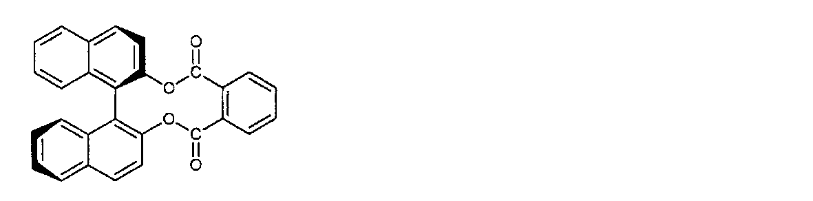
- axially asymmetric or planar asymmetric compounds include binaphthyl, helicene, paracyclophane and derivatives thereof.
- the optically active compound (chiral agent) may have a polymerizable group.
- the optically active compound has a polymerizable group and the rod-shaped liquid crystal compound used in combination also has a polymerizable group, a repeating unit derived from the rod-shaped liquid crystal compound by a polymerization reaction between the polymerizable optically active compound and the polymerizable rod-shaped liquid crystal compound. And a polymer having repeating units derived from an optically active compound can be formed.
- the polymerizable group of the polymerizable optically active compound is preferably a group of the same type as the polymerizable group of the polymerizable rod-shaped liquid crystal compound.
- the polymerizable group of the optically active compound is preferably an unsaturated polymerizable group, an epoxy group or an aziridinyl group, more preferably an unsaturated polymerizable group, and an ethylenically unsaturated polymerizable group. Is particularly preferable.
- the optically active compound may be a liquid crystal compound.
- the optically active compound in the liquid crystal composition is preferably 0.1 parts by weight or more and 20 parts by weight or less, and more preferably 1 part by weight or more and 10 parts by weight or less with respect to 100 parts by weight of the liquid crystal compound used in combination.
- the smaller the amount of the optically active compound used, the more preferably it does not affect the liquid crystallinity. Therefore, the optically active compound used as a chiral agent is preferably a compound that exhibits a strong twisting force so that a desired twisting orientation of a spiral pitch can be achieved even in a small amount. Examples of such a chiral agent exhibiting a strong twisting force include the chiral agents described in JP-A-2003-287623, and the chiral agents can be preferably used.
- the liquid crystal composition used for forming each light reflecting layer is preferably a polymerizable liquid crystal composition, and preferably contains a polymerization initiator accordingly. Since the cured liquid crystal composition is allowed to proceed with the curing reaction by irradiation with ultraviolet rays, the polymerization initiator used is preferably a photopolymerization initiator capable of initiating the polymerization reaction by irradiation with ultraviolet rays.
- the photopolymerization initiator is not particularly limited, and for example, 2-methyl-1- [4- (methylthio) phenyl] -2-morpholinopropane-1-one (BASF's "Irgacure 907"), 1-hydroxycyclohexyl.
- Phenyl ketone (BASF "Irgacure 184"), 4- (2-hydroxyethoxy) -phenyl (2-hydroxy-2-propyl) ketone (BASF “Irgacure 2959”), 1- (4-dodecyl) Phenyl) -2-hydroxy-2-methylpropan-1-one (Merck's "DaroCure 953”), 1- (4-isopropylphenyl) -2-hydroxy-2-methylpropan-1-one (Merck's) "Darocure 1116”), 2-hydroxy-2-methyl-1-phenylpropan-1-one (BASF “Irgacure 1173”), acetophenone compounds such as diethoxyacetophenone; benzoin, benzoin methyl ether, benzoin ethyl ether , Benzoin isopropyl ether, benzoin isobutyl ether, 2,2-dimethoxy-2-phenylacetophenone (BASF "Irga
- the content of the photopolymerization initiator in the polymerizable liquid crystal composition is not particularly limited, but is preferably 0.5 parts by weight or more and 10 parts by weight or less, more preferably 2 parts by weight, based on 100 parts by weight of the polymerizable liquid crystal compound. It is 5 parts by weight or more and 8 parts by weight or less.
- reaction aid is not particularly limited, and for example, triethanolamine, methyldiethanolamine, triisopropanolamine, n-butylamine, N-methyldiethanolamine, diethylaminoethyl methacrylate, Michler ketone, 4,4'-diethylaminophenone, 4-dimethyl.
- examples thereof include amine compounds such as ethyl aminobenzoate, ethyl 4-dimethylaminobenzoate (n-butoxy), and isoamyl 4-dimethylaminobenzoate.
- the content of the reaction aid in the polymerizable liquid crystal composition is not particularly limited, but it is preferably used within a range that does not affect the liquid crystal property of the polymerizable liquid crystal composition, and the polymerizable liquid crystal compound and the ultraviolet curable polymerization type are polymerized. It is preferably 0.5 parts by weight or more and 10 parts by weight or less, and more preferably 5 parts by weight or more and 8 parts by weight or less with respect to 100 parts by weight of the total of the sex compounds.
- the content of the reaction aid is preferably 0.5 to 2 times the content of the photopolymerization initiator.
- the liquid crystal composition further contains a solvent.
- a solvent is not particularly limited as long as it can dissolve the liquid crystal compound, chiral agent, etc. to be used, and examples thereof include methyl ethyl ketone, toluene, methyl isobutyl ketone, cyclopentanone, acetone, and anisole, and the solvent is soluble. Cyclopentanone having a good value is preferable. Further, these solvents can be added at an arbitrary ratio, only one type may be added, or a plurality of solvents may be used in combination. These solvents are dried and removed in a drying zone such as an oven or a film coater line.
- additives Add leveling agents, defoaming agents, ultraviolet absorbers, light stabilizers, antioxidants, polymerization inhibitors, cross-linking agents, plasticizers, inorganic fine particles, fillers, etc. to the liquid crystal composition, if necessary. It is also possible to further add the agent at an arbitrary ratio to give the liquid crystal composition the function of each additive.
- the leveling agent include fluorine-based compounds, silicone-based compounds, and acrylic-based compounds.
- the ultraviolet absorber include benzotriazole compounds, benzophenone compounds, triazine compounds and the like
- examples of the light stabilizer include hindered amine compounds and benzoate compounds
- antioxidants include phenol compounds and the like. Can be mentioned.
- polymerization inhibitor examples include methquinone, methylhydroquinone, hydroquinone and the like
- cross-linking agent examples include polyisocyanates and melamine compounds.
- Plasticizers include phthalates such as dimethylphthalate and diethylphthalate, trimeritic acid esters such as tris (2-ethylhexyl) trimerite, aliphatic dibasic acid esters such as dimethyl adipate and dibutyl adipate, tributyl phosphate and triphenyl.
- orthophosphates such as phosphates and acetates such as glycertriacetate and 2-ethylhexyl acetate.
- each light reflecting layer, the optical laminate and the polarizing element layer can be laminated via an adhesive layer, if necessary.
- the material for forming such an adhesive layer is preferably transparent. Examples of transparent resins that can be used as materials for forming an adhesive layer include acrylic resins and epoxy resins.
- Acrylic resin contains an acrylic monomer or oligomer as a main component and is cured by anionic polymerization, radical polymerization, or redox polymerization.
- acrylic resins include anionic polymerization type instant adhesives containing 2-cyanoacrylate as a main component, redox polymerization type acrylic adhesives containing methacrylic acid ester as a main component, and polyfunctional acrylics.
- examples thereof include a radical polymerization type ultraviolet curable adhesive containing an acid ester and a polyfunctional methacrylic acid ester as main components and irradiated with ultraviolet rays.
- the UV curable adhesive contains a (meth) acrylate-based monomer, a photopolymerization initiator and an additive.
- acrylic resins examples include trimethylolpropantri (meth) acrylate, pentaerythritol tri (meth) acrylate, pentaerythritol tetra (meth) acrylate, ditrimethylol propanetetra (meth) acrylate, dipentaerythritol pentaacrylate, and the like.
- Dipentaerythritol hexaacrylate reaction product of pentaerythritol tri (meth) acrylate with 1,6-hexamethylene diisocyanate, reaction product of pentaerythritol tri (meth) acrylate with isophorone diisocyanate, tris (acryloxyethyl) isocia Nurate, Tris (methacryloxyethyl) isocyanurate, reaction product of glycerol triglycidyl ether with (meth) acrylic acid, caprolactone-modified tris (acryloxyethyl) isocyanurate, trimethylpropantriglycidyl ether and (meth) acrylic Reaction product with acid, triglycerol di (meth) acrylate, reaction product with propylene glycol diglycidyl ether and (meth) acrylic acid, polypropylene glycol di (meth) acrylate, tripropylene glycol di (meth) acrylate, poly
- Epoxy resin contains an epoxy resin and a curing agent, preferably an amine compound, an acid anhydride, and a metal catalyst as optional components.
- the epoxy resin is not particularly limited as long as it has two or more epoxy groups in one molecule.
- bisphenol A type epoxy resin bisphenol F type epoxy resin, bisphenol S type epoxy resin, phenol novolac type epoxy resin.
- Examples thereof include an aliphatic epoxy resin and a urethane-modified epoxy resin, and two or more of these epoxy resins may be mixed and used. Further, if necessary, a monoepoxy compound such as butyl glycidyl ether, phenyl glycidyl ether, cresyl glycidyl ether, and glycidyl ether of an aliphatic alcohol may be blended in order to reduce the viscosity.
- a monoepoxy compound such as butyl glycidyl ether, phenyl glycidyl ether, cresyl glycidyl ether, and glycidyl ether of an aliphatic alcohol may be blended in order to reduce the viscosity.
- An adhesive can also be used as a material for forming an adhesive layer.
- the adhesive rubber-based, acrylic-based, silicone-based, and the like can be used, but acrylic-based adhesives are particularly desirable.
- acrylic pressure-sensitive adhesives include pressure-sensitive adhesives using (meth) acrylic polymers obtained by copolymerizing (meth) acrylic acid alkyl esters and other (meth) acrylic monomer components.
- the (meth) acrylic acid alkyl ester includes, for example, ethyl (meth) acrylic acid, isopropyl (meth) acrylic acid, n-butyl (meth) acrylic acid, isobutyl (meth) acrylic acid, pentyl (meth) acrylic acid, and the like.
- examples thereof include 2-ethylhexyl (meth) acrylate, isooctyl (meth) acrylate, n-octyl (meth) acrylate, isononyl (meth) acrylate, decyl (meth) acrylate, and lauryl (meth) acrylate.
- Examples of other (meth) acrylic monomer components include carboxyl group-containing monomers such as acrylic acid, methacrylic acid, itaconic acid, crotonic acid, maleic acid, and fumaric acid; 2-hydroxyethyl (meth) acrylate and 2-hydroxy.
- Hydroxyl group-containing monomers such as propyl (meth) acrylate, 4-hydroxybutyl (meth) acrylate, polyoxypropylene (meth) acrylate, caprolactone-modified (meth) acrylate; N-vinylpyrrolidone, N-vinylcaprolactam, acroylmorpholine, ( Examples thereof include nitrogen-containing monomers such as meta) acrylamide, dimethylaminoethyl (meth) acrylate, diethylaminoethyl (meth) acrylate and dimethylaminopropyl (meth) acrylate; and epoxy group-containing monomers such as glycidyl (meth) acrylate.
- a solvent may be added to the coating liquid of the adhesive to adjust the viscosity and improve the coatability.
- Solvents include acetate esters such as ethyl acetate, butyl acetate, methyl acetate; alcohols such as methanol, ethanol, propanol, isopropanol, benzyl alcohol; ketones such as methyl ethyl ketone, acetone, cyclopentanone, cyclohexanone; Basic solvents such as benzylamine, triethylamine and pyridine; and non-polar solvents such as cyclohexane, benzene, toluene, xylene, anisole, hexane and heptane can be mentioned. These solvents can be added at any ratio, and only one type may be added, or a plurality of components may be blended. These solvents are dried and removed in the drying zone of the oven and film coater line.
- the optical film according to the present embodiment may have an alignment layer between the light reflection layer in which the cholesteric liquid crystal phase laminated in the optical laminate is immobilized and the polarizing element layer.
- the alignment layer has a function of more precisely defining the orientation direction of the liquid crystal compound in the cholesteric liquid crystal phase.
- the oriented layer can be provided by means such as rubbing treatment of an organic compound (preferably a polymer), oblique vapor deposition of an inorganic compound, and formation of a layer having microgrooves. Further, an orientation layer in which an orientation function is generated by applying an electric field, applying a magnetic field, or irradiating light is also known.
- the alignment layer is preferably formed on the surface of the polymer film by a rubbing treatment.
- the alignment layer preferably has a certain degree of adhesion to both the light reflecting layer and the polarizing element layer that are adjacent to each other.
- an alignment layer is inserted into an optical laminate having three light-reflecting layers on which a cholesteric liquid crystal layer is fixed, first, two laminates having a light-reflecting layer and an alignment layer are prepared, and the laminate [ 1] (light reflecting layer [1] / alignment layer [1]) and laminated body [2] (light reflecting layer [2] / alignment layer [2]) are bonded together using an adhesive, and the alignment layer [2] A laminate [A] having a layer structure of 1] / light reflecting layer [1] / adhesive / light reflecting layer [2] / alignment layer [2] is produced.
- one of the alignment layers [2] is peeled off, and similarly, with a laminate [3] (light reflection layer [3] / alignment layer [3]) having a light-reflecting layer and an alignment layer prepared in advance.
- the laminate [A] produced as described above is bonded to each other using an adhesive, and the alignment layer [1] / light reflection layer [1] / adhesive / light reflection layer [2] / adhesive / light reflection
- a laminated body [B] having a layer structure of a layer [3] / an oriented layer [3] is produced.
- the alignment layer is interposed at the interface between the light reflecting layer on which the cholesteric liquid crystal phase is immobilized and the alignment layer with a weak peeling force capable of peeling.
- the interface for peeling the alignment layer is not particularly limited, but it is preferable to peel off at the interface between the light reflecting layer and the alignment layer in consideration of laminating the laminated body [3] in a separate step. ..
- a polymer of an organic compound is preferable, and a polymer that can be crosslinked by itself or a polymer that is crosslinked by a crosslinking agent is typically used. Moreover, you may use the polymer which has both functions.
- polymers examples include polymethylmethacrylate, acrylic acid / methacrylic acid copolymer, styrene / maleinimide copolymer, polyvinyl alcohol and modified polyvinyl alcohol, poly (N-methylolacrylamide), styrene / vinyltoluene copolymer, Polymers such as chlorosulfonated polyethylene, nitrocellulose, polyvinyl chloride, chlorinated polyolefin, polyester, polyimide, vinyl acetate / vinyl chloride copolymer, ethylene / vinyl acetate copolymer, carboxymethyl cellulose, gelatin, polyethylene, polypropylene, polycarbonate, etc. And compounds such as silane coupling agents.
- Examples of preferred polymers are water-soluble polymers such as poly (N-methylolacrylamide), carboxymethyl cellulose, gelatin, polyvinyl alcohol and modified polyvinyl alcohol, and examples thereof include gelatin, polyvinyl alcohol and modified polyvinyl alcohol.
- the thickness of the alignment layer is preferably 0.1 ⁇ m or more and 2.0 ⁇ m or less.
- an oriented layer is provided between the light reflecting layer of the cholesteric liquid crystal phase and the polarizing element layer, it is preferable to use an oriented layer having low birefringence from the viewpoint of degree of polarization, and triacetyl cellulose (TAC) having low birefringence. ), Polyethylene, acrylic and the like are preferable.
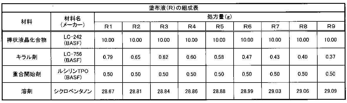
- a coating liquid (R) having the composition shown in Table 1 below and a coating liquid (L) having the composition shown in Table 2 below were prepared, respectively.
- Chiral agent Compound 1 (Compound described in JP-A-2002-179668)
- a cholesteric liquid crystal coating film (light reflection layer) was prepared by the following procedure, and the selective center reflection wavelength was evaluated.
- a PET film manufactured by Toyobo Co., Ltd., "trade name A4100", thickness 50 ⁇ m
- Each coating liquid was coated on a PET film at room temperature so as to have a predetermined thickness using a wire bar.
- the solvent was removed by heating at 150 ° C. for 3 minutes to obtain a cholesteric liquid crystal phase.
- a high-pressure mercury lamp manufactured by Harrison Toshiba Lighting Corp.: HX4000L
- HX4000L a high-pressure mercury lamp
- UV ultraviolet at 120 W output
- a cholesteric liquid crystal coating film light reflecting layer
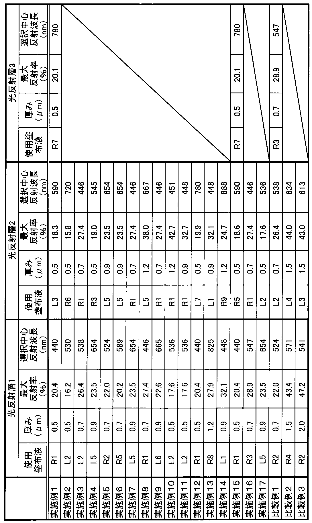
- Table 4 shows the thickness, selective center reflection wavelength, and maximum reflectance of each light reflecting layer used in each example.
- the obtained dyeing sheet was immersed in an aqueous solution containing 2.5 g / L of nickel acetate and 6.6 g / L of boric acid at 35 ° C. for 3 minutes. Further, the sheet was dried at room temperature for 3 minutes while maintaining the tension state, and then heat-treated at 70 ° C. for 3 minutes to prepare a polarizing element layer.
- the degree of polarization of the polarizing element layer was 99.5%.
- Example 1 ⁇ Manufacturing of optical film> [Example 1, Example 15, Comparative Example 1]
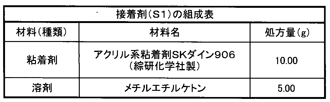
- the adjusted adhesive (S1) was applied to the cholesteric liquid crystal coating surface of the light reflecting layer 1 shown in Table 4 so that the thickness of the film after drying was 10 ⁇ m using a wire bar. After removing the solvent by heating at 40 ° C. for 1 minute, the cholesteric liquid crystal coating surface of the light reflecting layer 1 coated with the adhesive and the cholesteric liquid crystal coating surface of the light reflecting layer 2 described in Table 4 above are formed.
- the film was applied using a wire bar, and the cholesteric liquid crystal coating film of the light reflecting layer 3 described in Table 4 above was laminated in the same manner as in the procedure of laminating the two light reflecting layers.
- the PET film on the light reflecting layer 1 side and the PET film on the light reflecting layer 3 side are peeled off, respectively, and an optical laminate in which the light reflecting layer 1, the light reflecting layer 2, and the light reflecting layer 3 are laminated. (Light Reflection Layer 1 / Light Reflection Layer 2 / Light Reflection Layer 3) was produced.
- a polarizing element layer was bonded onto the light reflecting layer 1 using a urethane resin-based adhesive to prepare an optical film.
- Example 1 An optical laminate (light reflecting layer 1 / light reflecting layer 2) in which two layers of the light reflecting layer 1 and the light reflecting layer 2 shown in Table 4 are laminated is produced by the same procedure as described above. An optical film having a polarizing element layer on the light reflecting layer 1 was produced.
- the light-reflecting layer in which the right-handed spiral structure cholesteric liquid crystal phase is fixed As shown in Table 5 above, the light-reflecting layer in which the right-handed spiral structure cholesteric liquid crystal phase is fixed, the light reflecting layer in which the left-handed spiral structure cholesteric liquid crystal phase is fixed, and the right-handed spiral structure cholesteric liquid crystal phase are fixed.
- Example 15 also in the optical film produced in Example 15 in which all the light reflecting layers contained in the optical laminate are light reflecting layers RPRL, a high degree of polarization of 92.5% and a low haze value of 0.2% are obtained, respectively. Indicated. Further, as shown in Tables 4, 3 and 4, the optical films of Examples 1 and 15 had three light-reflecting layers having selective center reflection wavelengths of 440 nm, 590 nm and 780 nm, respectively. .. Further, in the wavelength region of 450 nm or more and 750 nm or less, the difference between the maximum reflectance and the average reflectance of the optical laminate and the difference between the average reflectance and the minimum reflectance of the optical laminate are both 5% or less. The produced optical film showed a metallic color tone, with the color of the reflected light being colorless in both the front direction and when tilted by 60 degrees.
- a light-reflecting layer in which a right-handed spiral cholesteric liquid crystal phase is fixed and a light-reflecting layer in which a left-handed spiral cholesteric liquid crystal phase is fixed are laminated, and the selective center reflection wavelength in two adjacent light-reflecting layers is set.
- the optical films prepared in Example 2 staggered by 190 nm intervals showed a high degree of polarization of 96.7% and a low haze value of 0.2%, respectively. Further, as shown in Table 4 and FIG. 5, the optical film of Example 2 had two light reflecting layers having selective center reflection wavelengths of 530 nm and 720 nm, respectively.
- the difference between the maximum reflectance and the average reflectance of the optical laminate and the difference between the average reflectance and the minimum reflectance of the optical laminate are both 5% or less.
- the produced optical film showed a metallic color tone, with the color of the reflected light being colorless in both the front direction and when tilted by 60 degrees.
- a light-reflecting layer in which a cholesteric liquid crystal phase having a right-handed spiral structure is fixed and a light-reflecting layer in which a cholesteric liquid crystal phase having a left-handed spiral structure is fixed are laminated, and the selective center reflection wavelength in two adjacent light-reflecting layers is
- the light-reflecting films of Examples 3 to 14 shifted by a maximum interval of 440 nm and a minimum interval of 65 nm all have a high degree of polarization of 90% or more and a low haze value of 0.2% or less. Each is shown.
- the optical films of Examples 3 to 14 include a plurality of light reflecting layers having different selective center reflection wavelengths, and a single selective center such as magenta color. It showed a tint of the reflected color that could not be reproduced at the reflected wavelength.
- the optical film of Example 14 contains a light-reflecting layer having a selective center wavelength of 850 nm or more, and therefore exhibits a very light-colored reflected light when tilted by 60 degrees. Was also confirmed.
- the optical films of Examples 16 and 17 have the same spectral spectra as the optical films of Examples 3 and 4.
- the degree of polarization was slightly lower than the degree of polarization of Examples 3 and 4. Both showed a high degree of polarization of 90% or more and a low haze value of 0.3% or less, respectively.
- the optical film of Comparative Example 1 in which the selective center reflection wavelengths of the two adjacent light reflection layers are shifted by intervals of 14 nm and 9 nm, respectively, has a spectral spectrum similar to that of a relatively single selective center wavelength. have.
- the degree of polarization was 90% or more, the haze value was 0.5%, which was inferior to the haze value as compared with other examples.
- the optical films of Comparative Example 2 and Comparative Example 3 have a maximum reflectance of 50% or more, so that the degree of polarization is low and 0.6% or more. It showed a high haze value.
- each of the optical laminates of Examples 1 to 17 exhibits a degree of polarization of 90% or more and a low haze value of less than 0.5%, each of the optical laminates produced in Examples 1 to 17 is produced.
- Optical films are suitable for use in optical members.
- each of the optical films produced in Examples 1, 2 and 15 is also colorless in color of the reflected light, and is therefore suitable for eyewear that requires colorless or silver-colored reflected light.
- the optical films produced in Examples 3 to 14 and 16 to 17 are suitable for eyewear that requires a reflection color that cannot be reproduced by a single selective center reflection wavelength.
- the present invention relates to an optical film having a plurality of light reflecting layers having different selective center reflection wavelengths, a high degree of polarization, and a low haze value.
- Such optical films are mainly suitable for application of eyewear (sunglasses, goggles, helmet visors, etc.).
Landscapes
- Physics & Mathematics (AREA)
- General Physics & Mathematics (AREA)
- Optics & Photonics (AREA)
- Ophthalmology & Optometry (AREA)
- Health & Medical Sciences (AREA)
- Nonlinear Science (AREA)
- General Health & Medical Sciences (AREA)
- Chemical & Material Sciences (AREA)
- Crystallography & Structural Chemistry (AREA)
- Mathematical Physics (AREA)
- Spectroscopy & Molecular Physics (AREA)
- Polarising Elements (AREA)
- Eyeglasses (AREA)
Abstract
Description
[1] 互いに異なる中心反射波長を有する2以上の光反射層が積層された光学積層体と、偏光素子層とを備え、
前記2以上の光反射層は、
右円偏光反射能を有する右巻き螺旋構造のコレステリック液晶相が固定化された、400nm以上900nm以下の範囲に選択中心反射波長を有する少なくとも1つの光反射層RPRLと、
左円偏光反射能を有する左巻き螺旋構造のコレステリック液晶相が固定化された、400nm以上900nm以下の範囲に選択中心反射波長を有する少なくとも1つの光反射層LPRLと、から選択され、
前記光反射層RPRL及び光反射層LPRLは、互いに隣接する2つの光反射層間でいずれも40nm以上500nm以下の間隔でずれた選択中心反射波長を有し、かつ
前記光学積層体の最大反射率が50%以下であることを特徴とする光学フィルム。
[2] 前記2以上の光反射層は前記光反射層RPRL及び光反射層LPRLの両方を含む、[1]に記載の光学フィルム。
[3] 偏光度が90%以上である、[1]又は[2]に記載の光学フィルム。
[4] 偏光度が95%以上である、[1]乃至[3]までのいずれかに記載の光学フィルム。
[5] ヘーズ値(Hz)が0.5%未満である、[1]乃至[4]までのいずれかに記載の光学フィルム。
[6] 450nm以上750nm以下の波長領域において、前記光学積層体の最大反射率と平均反射率との差が30%以下であり、かつ、前記光学積層体の平均反射率と最小反射率との差が15%である、[1]乃至[5]までのいずれかに記載の光学フィルム。
[7] [1]乃至[6]までのいずれかに記載の光学フィルムを備えるアイウェア。
図1は、複数の光反射層が積層された光学積層体の一例を示す。光学積層体1は、コレステリック液晶相が固定化された光反射層2、3、4及びこれらの光反射層2、3、4の間に形成された接着層5、6を備える。接着層5、6は、例えば、接着剤を用いて形成される。なお、接着剤を使用しなくても光反射層2、3、4を積層できる場合、接着層5、6を介することなく光反射層2、3、4を直接積層することができる。
図2は、本実施形態に係る光学フィルムの一例を示す。図2に示される光学フィルム9は、偏光素子で形成された偏光素子層8上に、接着層7を介して、図1に示される光学積層体1が設けられている。偏光素子層8の材料は、典型的にはPVA偏光フィルムが挙げられる。偏光素子層の製造方法は特に限定されないが、例えば、ポリビニルアルコール又はその誘導体から形成される高分子フィルムにヨウ素、二色性染料などの色素を吸着させ、次いで、該フィルムを一軸に延伸配向させることで偏光素子層8が製造される。色素としては、耐熱性の点から、二色性染料が好ましく、特にスルホン酸基をもつアゾ色素の直接染料が好ましい。また、光学積層体と偏光素子層とを積層する方法としては、特に限定されないが、高い接着力が得られることから接着層を介して貼り合わせることが望ましい。接着層としては、ホットメルト型接着剤と硬化型接着剤のいずれも使用可能である。通常、硬化型接着剤としては、アクリル樹脂系材料、ウレタン樹脂系材料、ポリエステル樹脂系材料、メラミン樹脂系材料、エポキシ樹脂系材料、シリコーン系材料等が使用でき、特に、曲げ加工時の接着力、加工性に優れることから、ウレタン樹脂系材料であるポリウレタンプレポリマーと硬化剤とを含む2液型の熱硬化性ウレタン樹脂が好ましい。光学積層体と偏光素子層を接着する接着剤には、調光染料を溶解させた接着剤を用いてもよい。
光反射層RPRL及び光反射層LPRLにおいて、各光反射層の形成に、硬化性の液晶組成物を用いることが好ましい。例えば、前記液晶組成物は、棒状液晶化合物、光学活性化合物(キラル化合物)、及び重合開始剤の各成分を少なくとも含有しており、各成分は2種以上含まれていてもよい。例えば、重合性の液晶化合物と非重合性の液晶化合物との併用が可能である。また、低分子液晶化合物と高分子液晶化合物との併用も可能である。更に、各種液晶化合物の配向の均一性、液晶組成物の塗布適性、得られる塗膜の強度を向上させるために、水平配向剤、ムラ防止剤、ハジキ防止剤、及び重合性モノマー等の種々の添加剤から選ばれる少なくとも1種を含有していてもよい。また、液晶組成物中には、必要に応じて、さらに重合禁止剤、酸化防止剤、紫外線吸収剤、光安定剤、色材、金属酸化物微粒子等を、光学性能を低下させない範囲で添加することができる。
棒状液晶化合物の例として、棒状ネマチック液晶化合物が挙げられる。棒状ネマチック液晶化合物として、例えば、アゾメチン類、アゾキシ類、シアノビフェニル類、シアノフェニルエステル類、安息香酸エステル類、シクロヘキサンカルボン酸フェニルエステル類、シアノフェニルシクロヘキサン類、シアノ置換フェニルピリミジン類、フェニルジオキサン類、トラン類及びアルケニルシクロヘキシルベンゾニトリル類が好ましく用いられる。また、棒状液晶化合物として、低分子液晶化合物だけではなく、高分子液晶化合物も用いることができる。
液晶組成物は、コレステリック液晶相を示すものであり、そのためには、光学活性化合物を含有していることが好ましい。ただし、棒状液晶化合物が不斉炭素原子を有する分子である場合、光学活性化合物を添加しなくても、コレステリック液晶相を安定的に形成することが可能な場合もある。光学活性化合物は、公知の種々のキラル剤(例えば、液晶デバイスハンドブック、第3章4-3項、TN、STN用カイラル剤、199頁、日本学術振興会第142委員会編、1989に記載)から選択することができる。光学活性化合物は、一般に不斉炭素原子を含むが、不斉炭素原子を含まない軸性不斉化合物又は面性不斉化合物もキラル剤として用いることができる。軸性不斉化合物又は面性不斉化合物の例には、ビナフチル、ヘリセン、パラシクロファン及びこれらの誘導体が含まれる。光学活性化合物(キラル剤)は、重合性基を有していてもよい。光学活性化合物が重合性基を有するとともに、併用する棒状液晶化合物も重合性基を有する場合、重合性光学活性化合物と重合性棒状液晶化合物との重合反応により、棒状液晶化合物から誘導される繰り返し単位と、光学活性化合物から誘導される繰り返し単位とを有するポリマーを形成することができる。この態様では、重合性光学活性化合物が有する重合性基は、重合性棒状液晶化合物が有する重合性基と同種の基であることが好ましい。したがって、光学活性化合物の重合性基も、不飽和重合性基、エポキシ基又はアジリジニル基であることが好ましく、不飽和重合性基であることが更に好ましく、エチレン性不飽和重合性基であることが特に好ましい。また、光学活性化合物は、液晶化合物であってもよい。
各光反射層の形成用に用いる液晶組成物は、重合性液晶組成物であることが好ましく、これに伴い重合開始剤を含有していることが好ましい。塗布された液晶組成物については、紫外線照射により硬化反応を進行させるので、使用する重合開始剤は、紫外線照射によって重合反応を開始可能な光重合開始剤であることが好ましい。光重合開始剤は特に限定されず、例えば、2-メチル-1-[4-(メチルチオ)フェニル]-2-モルホリノプロパン-1-オン(BASF社製「イルガキュアー907」)、1-ヒドロキシシクロヘキシルフェニルケトン(BASF社製「イルガキュアー184」)、4-(2-ヒドロキシエトキシ)-フェニル(2-ヒドロキシ-2-プロピル)ケトン(BASF社製「イルガキュアー2959」)、1-(4-ドデシルフェニル)-2-ヒドロキシ-2-メチルプロパン-1-オン(メルク社製「ダロキュアー953」)、1-(4-イソプロピルフェニル)-2-ヒドロキシ-2-メチルプロパン-1-オン(メルク社製「ダロキュアー1116」)、2-ヒドロキシ-2-メチル-1-フェニルプロパン-1-オン(BASF社製「イルガキュアー1173」)、ジエトキシアセトフェノン等のアセトフェノン化合物;ベンゾイン、ベンゾインメチルエーテル、ベンゾインエチルエーテル、ベンゾインイソプロピルエーテル、ベンゾインイソブチルエーテル、2,2-ジメトキシ-2-フェニルアセトフェノン(BASF社製「イルガキュアー651」)等のベンゾイン化合物;ベンゾイル安息香酸、ベンゾイル安息香酸メチル、4-フェニルベンゾフェノン、ヒドロキシベンゾフェノン、4-ベンゾイル-4’-メチルジフェニルサルファイド、3,3’-ジメチル-4-メトキシベンゾフェノン(日本化薬社製「カヤキュアーMBP」)等のベンゾフェノン化合物;及び、チオキサントン、2-クロルチオキサントン(日本化薬社製「カヤキュアーCTX」)、2-メチルチオキサントン、2,4-ジメチルチオキサントン(日本化薬社製「カヤキュアーRTX」)、イソプロピルチオキサントン、2,4-ジクロオチオキサントン(日本化薬社製「カヤキュアーCTX」)、2,4-ジエチルチオキサントン(日本化薬社製「カヤキュアーDETX」)、2,4-ジイソプロピルチオキサントン(日本化薬社製「カヤキュアーDITX 」)等のチオキサントン化合物等が挙げられる。これらの光重合開始剤は、単独で用いられてもよいし、2種以上が併用されてもよい。
液晶組成物には、さらに溶剤が含まれる。このような溶剤は、使用する液晶化合物、キラル剤等を溶解できれば、特に限定されるものではなく、例えば、メチルエチルケトン、トルエン、メチルイソブチルケトン、シクロペンタノン、アセトン、アニソールなどがあげられ、溶解性が良好なシクロペンタノンが好ましい。また、これらの溶剤は任意の割合で加えることができ、1種類のみを加えてもよく、複数の溶剤を併用してもよい。これら溶剤は、オーブン、フィルムコーターライン等の乾燥ゾーンにて乾燥除去される。
液晶組成物に、必要に応じてレベリング剤、消泡剤、紫外線吸収剤、光安定化剤、酸化防止剤、重合禁止剤架橋剤、可塑剤、無機微粒子、フィラー等の添加剤を任意の割合で更に添加し、液晶組成物にそれぞれの添加剤が有する機能を付与させることも可能である。レベリング剤としてはフッ素系化合物、シリコーン系化合物、アクリル系化合物等が挙げられる。紫外線吸収剤としては、ベンゾトリアゾール系化合物、ベンゾフェノン系化合物、トリアジン系化合物等が挙げられ、光安定化剤としてはヒンダードアミン系化合物、ベンゾエート系化合物等が挙げられ、酸化防止剤としてはフェノール系化合物等が挙げられる。重合禁止剤としては、メトキノン、メチルハイドロキノン、ハイドロキノン等が挙げられ、架橋剤としては、ポリイソシアネート類、メラミン化合物等が挙げられる。可塑剤としてはジメチルフタレートやジエチルフタレートのようなフタル酸エステル、トリス(2-エチルヘキシル)トリメリテートのようなトリメリト酸エステル、ジメチルアジペートやジブチルアジペートのような脂肪族二塩基酸エステル、トリブチルホスフェートやトリフェニルホスフェートのような正燐酸エステル、グリセルトリアセテートや2-エチルヘキシルアセテートのような酢酸エステルが挙げられる。
本実施態様に係る光学積層体において、必要に応じて、各光反射層、光学積層体と偏光素子層を、接着層を介して積層することができる。光学フィルムの光学部材への適用を考慮すると、このような接着層を形成するための材料は、透明であることが好ましい。接着層形成用材料に使用可能な透明な樹脂の例として、アクリル系樹脂、エポキシ系樹脂が挙げられる。
アクリル系樹脂は、アクリル系モノマー又はオリゴマーを主成分とし、アニオン重合やラジカル重合、レドックス重合によって硬化するものである。このようなアクリル系樹脂としては、例えば、2-シアノアクリル酸エステルを主成分とするアニオン重合型の瞬間接着剤、メタクリル酸エステルを主成分とするレドックス重合型のアクリル系接着剤、多官能アクリル酸エステル、多官能メタクリル酸エステルを主成分とする紫外線照射によるラジカル重合型の紫外線硬化型接着剤等が挙げられる。紫外線硬化型接着剤は(メタ)アクリレート系モノマー、光重合開始剤及び添加剤を含む。
エポキシ系樹脂は、エポキシ樹脂と硬化剤、好ましくはアミン系化合物、酸無水物、金属触媒を任意成分として含んでいる。エポキシ樹脂としては、1分子中に2個以上のエポキシ基をもつものであれば特に制限はなく、例えばビスフェノールA型エポキシ樹脂、ビスフェノールF型エポキシ樹脂、ビスフェノールS型エポキシ樹脂、フェノールノボラック型エポキシ樹脂、脂環式エポキシ樹脂、複素環式エポキシ樹脂、グリシジルエステル系エポキシ樹脂、グリシジルアミン系エポキシ樹脂、プロム化エポキシ樹脂、水添ビスフェノールA型エポキシ樹脂、プロピレングリコールグリシジルエーテル又はペンタエリスリトールポリグリシジルエーテルなどの脂肪族系エポキシ樹脂、ウレタン変性エポキシ樹脂等が挙げられ、これらエポキシ樹脂は2種以上混合して用いてもよい。また、必要に応じて、粘度低下のためにブチルグリシジルエーテル、フェニルグリシジルエーテル、クレシルグリシジルエーテル、脂肪族アルコールのグリシジルエーテルなどのモノエポキシ化合物を配合してもよい。
アクリル系粘着剤としては、(メタ)アクリル酸アルキルエステルや他の(メタ)アクリル系モノマー成分を共重合した(メタ)アクリル系ポリマーを用いた粘着剤が挙げられる。
本実施形態に係る光学フィルムは、光学積層体中に積層されているコレステリック液晶相が固定化された光反射層と偏光素子層との間に配向層を有していてもよい。配向層は、コレステリック液晶相中の液晶化合物の配向方向をより精密に規定する機能を有する。配向層は、有機化合物(好ましくはポリマー)のラビング処理、無機化合物の斜方蒸着、マイクログルーブを有する層の形成等の手段で設けることができる。さらには、電場の付与、磁場の付与、又は光照射により配向機能が生じる配向層も知られている。配向層は、ポリマーの膜の表面に、ラビング処理により形成することが好ましい。
下記表1に示す組成の塗布液(R)及び表2に示す組成の塗布液(L)をそれぞれ調製した。

下記表3に示す組成の接着剤を調製した。
調製した16種類の塗布液(R1~R9)、(L1~L7)を用い、下記の手順にてそれぞれコレステリック液晶の塗膜(光反射層)を作製し、選択中心反射波長を評価した。各光反射層の基板としては、ラビング処理が施された下塗り層がないPETフィルム(東洋紡績社製、「商品名 A4100」、厚さ50μm)を使用した。
(1)各塗布液を、ワイヤーバーを用いて、所定の厚みになるようPETフィルム上に室温にて塗布した。
(2)150℃にて3分間加熱して溶剤の除去とともにコレステリック液晶相とした。次いで、高圧水銀ランプ(ハリソン東芝ライティング社製:HX4000L)を120W出力、5~10秒間UV照射し、コレステリック液晶相を固定して、コレステリック液晶塗膜(光反射層)を作製した。
(3)分光光度計(島津製作所社製「MPC-3100」)を用いて、作製した光反射層の反射スペクトルを測定し、選択中心反射波長及び最大反射率を求めた。各実施例に使用した各光反射層の厚み、選択中心反射波長及び最大反射率を下記表4に示す。
ポリビニルアルコール(クラレ社製、商品名「クラレビニロン#750」)を、クロランチンファストレッド(C.I.28160)0.25g/L、クリソフェニン(C.I.24895)0.18g/L、ソロフェニルブルー4GL(C.I.34200)1.0g/L及び硫酸ナトリウム10g/Lを含む水溶液中に浸漬し、35℃で3分間染色した後、溶液中で4倍に延伸した。次いで、得られた染色シートを酢酸ニッケル2.5g/L及びホウ酸6.6g/Lを含む水溶液中35℃で3分浸漬した。更に、そのシートを緊張状態が保持された状態で室温にて3分乾燥した後、70℃で3分間加熱処理し、偏光素子層を作製した。偏光素子層を、分光光度計を用いて絶対偏光法により偏光度を測定した結果、偏光素子層の偏光度は99.5%であった。
[実施例1、実施例15、比較例1]
調整した接着剤(S1)を、ワイヤーバーを用いて、乾燥後の膜の厚みが10μmになるように表4に記載した光反射層1のコレステリック液晶塗膜面に塗布した。40℃にて1分間加熱して溶剤を除去した後、接着剤が塗布された光反射層1のコレステリック液晶塗膜面と上記表4に記載した光反射層2のコレステリック液晶塗膜面とを、ハンドローラーを用いて合わせ、高圧水銀ランプ(ハリソン東芝ライティング社製「HX4000L」)を120W出力、5~10秒間UV照射して接着剤を硬化させて、光反射層1と、光反射層2の2層を積層した。その後、光反射層2側のPETフィルムを剥離し、当該PETフィルムを剥離した側の光反射層2のコレステリック液晶塗膜面に、接着剤(S1)を乾燥後の膜の厚みが10μmになるようにワイヤーバーを用いて塗布し、2つの光反射層を積層した手順と同様に上記表4に記載した光反射層3のコレステリック液晶塗膜を積層した。次いで、光反射層1側のPETフィルムと光反射層3側のPETフィルムをそれぞれ剥離し、光反射層1と、光反射層2と、光反射層3の3層が積層された光学積層体(光反射層1/光反射層2/光反射層3)を作製した。次に、光反射層1上にウレタン樹脂系接着剤を用いて偏光素子層を貼り合わせて、光学フィルムを作製した。
実施例1上記と同様の手順により、表4に記載した光反射層1と、光反射層2の2層が積層された光学積層体(光反射層1/光反射層2)を作製し、光反射層1上に偏光素子層を有する光学フィルムを作製した。
分光光度計(島津製作所社製「MPC-3100」)を用いて、実施例1~17及び比較例1~3で作製した各光学積層体の反射スペクトルを測定し、450nm~750nmの波長領域の平均反射率、最小反射率及び最大反射率、また、400nm~900nmの波長領域の最小反射率及び最大反射率を求めた。得られた結果を下記表5に示す。
実施例1~17及び比較例1~3で作製した光学フィルムの正面方向及び60度傾斜させた際の色味を確認した。得られた結果を下記表5に示す。
実施例1~17及び比較例1~3で作製した光学フィルムを、分光光度計を用いて、絶対偏光法により偏光度を評価した。得られた結果を下記表5に示す。
実施例1~17及び比較例1~3で作製した光学フィルムを、日本電色社製のヘーズメーターを用いてヘーズを評価した。得られた結果を下記表5に示す。

2 光反射層
3 光反射層
4 光反射層
5 接着層
6 接着層
7 接着層
8 偏光素子層
9 光学フィルム
Claims (7)
- 互いに異なる中心反射波長を有する2以上の光反射層が積層された光学積層体と、偏光素子層とを備え、
前記2以上の光反射層は、
右円偏光反射能を有する右巻き螺旋構造のコレステリック液晶相が固定化された、400nm以上900nm以下の範囲に選択中心反射波長を有する少なくとも1つの光反射層RPRLと、
左円偏光反射能を有する左巻き螺旋構造のコレステリック液晶相が固定化された、400nm以上900nm以下の範囲に選択中心反射波長を有する少なくとも1つの光反射層LPRLと、から選択され、
前記光反射層RPRL及び前記光反射層LPRLは、互いに隣接する2つの光反射層間でいずれも40nm以上500nm以下の間隔でずれた選択中心反射波長を有し、かつ
前記光学積層体の最大反射率が50%以下であることを特徴とする光学フィルム。 - 前記2以上の光反射層は前記光反射層RPRL及び光反射層LPRLの両方を含む、請求項1に記載の光学フィルム。
- 偏光度が90%以上である、請求項1又は2に記載の光学フィルム。
- 偏光度が95%以上である、請求項1乃至3までのいずれか一項に記載の光学フィルム。
- ヘーズ値(Hz)が0.5%未満である、請求項1乃至4までのいずれか一項に記載の光学フィルム。
- 450nm以上750nm以下の波長領域において、前記光学積層体の最大反射率と平均反射率との差が30%以下であり、かつ、前記光学積層体の平均反射率と最小反射率との差が15%である、請求項1乃至5までのいずれか一項に記載の光学フィルム。
- 請求項1乃至6までのいずれか一項に記載の光学フィルムを備えるアイウェア。
Priority Applications (5)
| Application Number | Priority Date | Filing Date | Title |
|---|---|---|---|
| JP2020544555A JP6841981B1 (ja) | 2019-03-28 | 2020-03-24 | 光学フィルム及びアイウェア |
| KR1020217030694A KR102889627B1 (ko) | 2019-03-28 | 2020-03-24 | 광학 필름 및 아이웨어 |
| CN202080024976.6A CN113646672B (zh) | 2019-03-28 | 2020-03-24 | 光学膜及眼用器具 |
| EP20776446.5A EP3982174B1 (en) | 2019-03-28 | 2020-03-24 | Optical film and eyewear |
| US17/480,559 US12158655B2 (en) | 2019-03-28 | 2021-09-21 | Optical film and eyewear |
Applications Claiming Priority (2)
| Application Number | Priority Date | Filing Date | Title |
|---|---|---|---|
| JP2019-063657 | 2019-03-28 | ||
| JP2019063657 | 2019-03-28 |
Related Child Applications (1)
| Application Number | Title | Priority Date | Filing Date |
|---|---|---|---|
| US17/480,559 Continuation US12158655B2 (en) | 2019-03-28 | 2021-09-21 | Optical film and eyewear |
Publications (1)
| Publication Number | Publication Date |
|---|---|
| WO2020196449A1 true WO2020196449A1 (ja) | 2020-10-01 |
Family
ID=72611059
Family Applications (1)
| Application Number | Title | Priority Date | Filing Date |
|---|---|---|---|
| PCT/JP2020/012836 Ceased WO2020196449A1 (ja) | 2019-03-28 | 2020-03-24 | 光学フィルム及びアイウェア |
Country Status (7)
| Country | Link |
|---|---|
| US (1) | US12158655B2 (ja) |
| EP (1) | EP3982174B1 (ja) |
| JP (2) | JP6841981B1 (ja) |
| KR (1) | KR102889627B1 (ja) |
| CN (1) | CN113646672B (ja) |
| TW (1) | TWI844652B (ja) |
| WO (1) | WO2020196449A1 (ja) |
Cited By (5)
| Publication number | Priority date | Publication date | Assignee | Title |
|---|---|---|---|---|
| WO2022025052A1 (ja) * | 2020-07-30 | 2022-02-03 | 日本化薬株式会社 | 多層光反射フィルム及びこれを備えたアイウェア |
| WO2022123946A1 (ja) * | 2020-12-09 | 2022-06-16 | 富士フイルム株式会社 | 反射フィルム、ウインドシールドガラスおよびヘッドアップディスプレイシステム |
| JPWO2022196785A1 (ja) * | 2021-03-18 | 2022-09-22 | ||
| JPWO2022196784A1 (ja) * | 2021-03-18 | 2022-09-22 | ||
| WO2024204224A1 (ja) * | 2023-03-28 | 2024-10-03 | 日本化薬株式会社 | 光学積層体、偏光レンズ及びアイウェア |
Families Citing this family (2)
| Publication number | Priority date | Publication date | Assignee | Title |
|---|---|---|---|---|
| WO2020235413A1 (ja) * | 2019-05-17 | 2020-11-26 | 株式会社ポラテクノ | 光学素子又は偏光板及びこれらを用いたアイウェア |
| WO2023145683A1 (ja) * | 2022-01-25 | 2023-08-03 | 日本化薬株式会社 | 光学フィルム及びアイウェア |
Citations (5)
| Publication number | Priority date | Publication date | Assignee | Title |
|---|---|---|---|---|
| WO2016002582A1 (ja) * | 2014-07-01 | 2016-01-07 | 日本化薬株式会社 | 光学フィルムおよびこれを用いた光学積層体 |
| WO2016098732A1 (ja) * | 2014-12-19 | 2016-06-23 | 日本化薬株式会社 | 光反射フィルム及びこれを有する積層体 |
| WO2017086067A1 (ja) * | 2015-11-19 | 2017-05-26 | 日本化薬株式会社 | アイウェア用光学フィルム、並びにこれを有するアイウェア用機能性フィルム、アイウェア用光学積層体およびアイウェア |
| WO2017175581A1 (ja) * | 2016-04-07 | 2017-10-12 | 日本化薬株式会社 | 光反射フィルム、ならびにこれを用いた光制御フィルムおよびミラーディスプレイ |
| JP2017198981A (ja) * | 2016-04-08 | 2017-11-02 | 日本化薬株式会社 | 光反射フィルム、ならびにこれを用いた光学フィルム、機能性ガラスおよびヘッドアップディスプレイ |
Family Cites Families (24)
| Publication number | Priority date | Publication date | Assignee | Title |
|---|---|---|---|---|
| US4683327A (en) | 1985-06-24 | 1987-07-28 | Celanese Corporation | Anisotropic heat-curable acrylic terminated monomers |
| JPH01272551A (ja) | 1988-04-22 | 1989-10-31 | Dainippon Printing Co Ltd | 重合性2官能アクリレートモノマー |
| JP3228348B2 (ja) | 1992-07-03 | 2001-11-12 | キヤノン株式会社 | 高分子液晶化合物、液晶組成物および液晶素子 |
| JP3513888B2 (ja) | 1993-08-16 | 2004-03-31 | 大日本インキ化学工業株式会社 | 液晶表示素子及びその製造方法 |
| DE69422256D1 (de) | 1993-10-15 | 2000-01-27 | Merck Patent Gmbh | Reaktive Flüssigkristallverbindungen |
| DE4405316A1 (de) | 1994-02-19 | 1995-08-24 | Basf Ag | Neue polymerisierbare flüssigkristalline Verbindungen |
| DE4408170A1 (de) | 1994-03-11 | 1995-09-14 | Basf Ag | Neue polymerisierbare flüssigkristalline Verbindungen |
| DE19532408A1 (de) | 1995-09-01 | 1997-03-06 | Basf Ag | Polymerisierbare flüssigkristalline Verbindungen |
| GB2306470B (en) | 1995-10-05 | 1999-11-03 | Merck Patent Gmbh | Reactive liquid crystalline compound |
| DE19649056A1 (de) | 1996-11-27 | 1998-05-28 | Basf Ag | Polymerisierbare Oligomesogene |
| AU7227698A (en) | 1997-05-22 | 1998-12-11 | Rolic Ag | New polymerisable liquid crystalline compounds |
| JP3963035B2 (ja) | 1997-09-05 | 2007-08-22 | 大日本インキ化学工業株式会社 | 液晶性(メタ)アクリレート化合物と組成物及びこれを用いた光学異方体 |
| JP3401743B2 (ja) * | 1997-10-22 | 2003-04-28 | 日東電工株式会社 | 偏光素子、偏光光源装置及び液晶表示装置 |
| US6613246B2 (en) | 2000-03-13 | 2003-09-02 | Fuji Photo Film Co., Ltd. | Polymerizable liquid crystal compound having amido bond between two cyclic groups |
| JP4309072B2 (ja) | 2000-03-13 | 2009-08-05 | 富士フイルム株式会社 | 重合性液晶化合物および光学異方性素子 |
| JP2002179668A (ja) | 2000-12-15 | 2002-06-26 | Fuji Photo Film Co Ltd | 光学活性化合物、液晶キラル剤、液晶組成物、液晶カラーフィルター、光学フイルム及び記録媒体 |
| JP3981638B2 (ja) | 2002-01-23 | 2007-09-26 | 日東電工株式会社 | 光学フィルム、その製造方法、およびこれを用いた位相差フィルムならびに偏光板 |
| WO2003062874A1 (en) | 2002-01-23 | 2003-07-31 | Nitto Denko Corporation | Optical compensation plate and deflecting plate using the same |
| JP5308420B2 (ja) * | 2010-10-04 | 2013-10-09 | 富士フイルム株式会社 | 光反射性フィルムおよびその製造方法 |
| JP5777463B2 (ja) * | 2011-09-15 | 2015-09-09 | 富士フイルム株式会社 | フィルム、赤外反射板、積層体および合わせガラス |
| JP6102835B2 (ja) | 2014-06-19 | 2017-03-29 | Jfeスチール株式会社 | 鋼板のチャタマーク防止方法 |
| WO2017175829A1 (ja) * | 2016-04-08 | 2017-10-12 | 日本化薬株式会社 | アイウェア用光学フィルム、並びにこれを用いた光学積層体およびアイウェア |
| WO2017175830A1 (ja) * | 2016-04-08 | 2017-10-12 | 日本化薬株式会社 | アイウェア用光学フィルム、並びにこれを用いた光学積層体およびアイウェア |
| JPWO2018186369A1 (ja) | 2017-04-06 | 2020-02-20 | 日本化薬株式会社 | 遮光機能付きアイウェア用光学フィルム、並びにこれを用いた光学積層体および遮光機能付きアイウェア |
-
2020
- 2020-03-24 CN CN202080024976.6A patent/CN113646672B/zh active Active
- 2020-03-24 JP JP2020544555A patent/JP6841981B1/ja active Active
- 2020-03-24 EP EP20776446.5A patent/EP3982174B1/en active Active
- 2020-03-24 WO PCT/JP2020/012836 patent/WO2020196449A1/ja not_active Ceased
- 2020-03-24 KR KR1020217030694A patent/KR102889627B1/ko active Active
- 2020-03-26 TW TW109110252A patent/TWI844652B/zh active
-
2021
- 2021-02-01 JP JP2021014073A patent/JP2021076861A/ja active Pending
- 2021-09-21 US US17/480,559 patent/US12158655B2/en active Active
Patent Citations (5)
| Publication number | Priority date | Publication date | Assignee | Title |
|---|---|---|---|---|
| WO2016002582A1 (ja) * | 2014-07-01 | 2016-01-07 | 日本化薬株式会社 | 光学フィルムおよびこれを用いた光学積層体 |
| WO2016098732A1 (ja) * | 2014-12-19 | 2016-06-23 | 日本化薬株式会社 | 光反射フィルム及びこれを有する積層体 |
| WO2017086067A1 (ja) * | 2015-11-19 | 2017-05-26 | 日本化薬株式会社 | アイウェア用光学フィルム、並びにこれを有するアイウェア用機能性フィルム、アイウェア用光学積層体およびアイウェア |
| WO2017175581A1 (ja) * | 2016-04-07 | 2017-10-12 | 日本化薬株式会社 | 光反射フィルム、ならびにこれを用いた光制御フィルムおよびミラーディスプレイ |
| JP2017198981A (ja) * | 2016-04-08 | 2017-11-02 | 日本化薬株式会社 | 光反射フィルム、ならびにこれを用いた光学フィルム、機能性ガラスおよびヘッドアップディスプレイ |
Cited By (10)
| Publication number | Priority date | Publication date | Assignee | Title |
|---|---|---|---|---|
| WO2022025052A1 (ja) * | 2020-07-30 | 2022-02-03 | 日本化薬株式会社 | 多層光反射フィルム及びこれを備えたアイウェア |
| WO2022123946A1 (ja) * | 2020-12-09 | 2022-06-16 | 富士フイルム株式会社 | 反射フィルム、ウインドシールドガラスおよびヘッドアップディスプレイシステム |
| JPWO2022123946A1 (ja) * | 2020-12-09 | 2022-06-16 | ||
| EP4261575A4 (en) * | 2020-12-09 | 2024-06-19 | FUJIFILM Corporation | REFLECTIVE FILM, WINDSHIELD GLASS AND HEAD-UP DISPLAY SYSTEM |
| US12072597B2 (en) | 2020-12-09 | 2024-08-27 | Fujifilm Corporation | Reflection film, windshield glass, and head-up display system |
| JP7649800B2 (ja) | 2020-12-09 | 2025-03-21 | 富士フイルム株式会社 | 反射フィルム、ウインドシールドガラスおよびヘッドアップディスプレイシステム |
| JPWO2022196785A1 (ja) * | 2021-03-18 | 2022-09-22 | ||
| JPWO2022196784A1 (ja) * | 2021-03-18 | 2022-09-22 | ||
| EP4310559A4 (en) * | 2021-03-18 | 2025-03-12 | Nippon Kayaku Kabushiki Kaisha | Optcal laminate and eyewear using same |
| WO2024204224A1 (ja) * | 2023-03-28 | 2024-10-03 | 日本化薬株式会社 | 光学積層体、偏光レンズ及びアイウェア |
Also Published As
| Publication number | Publication date |
|---|---|
| KR102889627B1 (ko) | 2025-11-21 |
| US12158655B2 (en) | 2024-12-03 |
| JPWO2020196449A1 (ja) | 2021-04-08 |
| JP2021076861A (ja) | 2021-05-20 |
| EP3982174A1 (en) | 2022-04-13 |
| TWI844652B (zh) | 2024-06-11 |
| EP3982174A4 (en) | 2023-07-26 |
| CN113646672A (zh) | 2021-11-12 |
| US20220004028A1 (en) | 2022-01-06 |
| CN113646672B (zh) | 2023-09-22 |
| KR20210144719A (ko) | 2021-11-30 |
| EP3982174B1 (en) | 2025-09-03 |
| TW202043026A (zh) | 2020-12-01 |
| JP6841981B1 (ja) | 2021-03-10 |
Similar Documents
| Publication | Publication Date | Title |
|---|---|---|
| JP6841981B1 (ja) | 光学フィルム及びアイウェア | |
| JP6739337B2 (ja) | 光学フィルムおよびこれを用いた光学積層体 | |
| JP6840733B2 (ja) | アイウェア用光学フィルム、並びにこれを用いた光学積層体およびアイウェア | |
| JP6689755B2 (ja) | 光反射フィルム及びこれを有する積層体 | |
| JP6840734B2 (ja) | アイウェア用光学フィルム、並びにこれを用いた光学積層体およびアイウェア | |
| WO2022025052A1 (ja) | 多層光反射フィルム及びこれを備えたアイウェア | |
| WO2023145683A1 (ja) | 光学フィルム及びアイウェア | |
| WO2023167293A1 (ja) | 液晶組成物、光反射層、光学積層体、及びアイウェア | |
| WO2021206024A1 (ja) | 光学フィルム、並びにこれを有する光学積層体およびアイウェア | |
| HK1237419A1 (en) | Light-reflective film and laminate having same | |
| HK1237419B (zh) | 光反射膜和具有该光反射膜的层叠体 |
Legal Events
| Date | Code | Title | Description |
|---|---|---|---|
| ENP | Entry into the national phase |
Ref document number: 2020544555 Country of ref document: JP Kind code of ref document: A |
|
| 121 | Ep: the epo has been informed by wipo that ep was designated in this application |
Ref document number: 20776446 Country of ref document: EP Kind code of ref document: A1 |
|
| NENP | Non-entry into the national phase |
Ref country code: DE |
|
| ENP | Entry into the national phase |
Ref document number: 2020776446 Country of ref document: EP Effective date: 20211028 |
|
| WWG | Wipo information: grant in national office |
Ref document number: 2020776446 Country of ref document: EP |