WO2020196477A1 - 熱伝導性樹脂シート、積層放熱シート、放熱性回路基板、及び、パワー半導体デバイス - Google Patents
熱伝導性樹脂シート、積層放熱シート、放熱性回路基板、及び、パワー半導体デバイス Download PDFInfo
- Publication number
- WO2020196477A1 WO2020196477A1 PCT/JP2020/012892 JP2020012892W WO2020196477A1 WO 2020196477 A1 WO2020196477 A1 WO 2020196477A1 JP 2020012892 W JP2020012892 W JP 2020012892W WO 2020196477 A1 WO2020196477 A1 WO 2020196477A1
- Authority
- WO
- WIPO (PCT)
- Prior art keywords
- heat
- resin sheet
- heat conductive
- mass
- resin
- Prior art date
- Legal status (The legal status is an assumption and is not a legal conclusion. Google has not performed a legal analysis and makes no representation as to the accuracy of the status listed.)
- Ceased
Links
Images


Classifications
-
- C—CHEMISTRY; METALLURGY
- C09—DYES; PAINTS; POLISHES; NATURAL RESINS; ADHESIVES; COMPOSITIONS NOT OTHERWISE PROVIDED FOR; APPLICATIONS OF MATERIALS NOT OTHERWISE PROVIDED FOR
- C09K—MATERIALS FOR MISCELLANEOUS APPLICATIONS, NOT PROVIDED FOR ELSEWHERE
- C09K5/00—Heat-transfer, heat-exchange or heat-storage materials, e.g. refrigerants; Materials for the production of heat or cold by chemical reactions other than by combustion
- C09K5/08—Materials not undergoing a change of physical state when used
- C09K5/14—Solid materials, e.g. powdery or granular
-
- B—PERFORMING OPERATIONS; TRANSPORTING
- B32—LAYERED PRODUCTS
- B32B—LAYERED PRODUCTS, i.e. PRODUCTS BUILT-UP OF STRATA OF FLAT OR NON-FLAT, e.g. CELLULAR OR HONEYCOMB, FORM
- B32B15/00—Layered products comprising a layer of metal
- B32B15/04—Layered products comprising a layer of metal comprising metal as the main or only constituent of a layer, which is next to another layer of the same or of a different material
- B32B15/08—Layered products comprising a layer of metal comprising metal as the main or only constituent of a layer, which is next to another layer of the same or of a different material of synthetic resin
-
- B—PERFORMING OPERATIONS; TRANSPORTING
- B32—LAYERED PRODUCTS
- B32B—LAYERED PRODUCTS, i.e. PRODUCTS BUILT-UP OF STRATA OF FLAT OR NON-FLAT, e.g. CELLULAR OR HONEYCOMB, FORM
- B32B15/00—Layered products comprising a layer of metal
- B32B15/20—Layered products comprising a layer of metal comprising aluminium or copper
-
- B—PERFORMING OPERATIONS; TRANSPORTING
- B32—LAYERED PRODUCTS
- B32B—LAYERED PRODUCTS, i.e. PRODUCTS BUILT-UP OF STRATA OF FLAT OR NON-FLAT, e.g. CELLULAR OR HONEYCOMB, FORM
- B32B27/00—Layered products comprising a layer of synthetic resin
- B32B27/18—Layered products comprising a layer of synthetic resin characterised by the use of special additives
- B32B27/20—Layered products comprising a layer of synthetic resin characterised by the use of special additives using fillers, pigments, thixotroping agents
-
- B—PERFORMING OPERATIONS; TRANSPORTING
- B32—LAYERED PRODUCTS
- B32B—LAYERED PRODUCTS, i.e. PRODUCTS BUILT-UP OF STRATA OF FLAT OR NON-FLAT, e.g. CELLULAR OR HONEYCOMB, FORM
- B32B27/00—Layered products comprising a layer of synthetic resin
- B32B27/28—Layered products comprising a layer of synthetic resin comprising synthetic resins not wholly covered by any one of the sub-groups B32B27/30 - B32B27/42
- B32B27/285—Layered products comprising a layer of synthetic resin comprising synthetic resins not wholly covered by any one of the sub-groups B32B27/30 - B32B27/42 comprising polyethers
-
- B—PERFORMING OPERATIONS; TRANSPORTING
- B32—LAYERED PRODUCTS
- B32B—LAYERED PRODUCTS, i.e. PRODUCTS BUILT-UP OF STRATA OF FLAT OR NON-FLAT, e.g. CELLULAR OR HONEYCOMB, FORM
- B32B27/00—Layered products comprising a layer of synthetic resin
- B32B27/28—Layered products comprising a layer of synthetic resin comprising synthetic resins not wholly covered by any one of the sub-groups B32B27/30 - B32B27/42
- B32B27/288—Layered products comprising a layer of synthetic resin comprising synthetic resins not wholly covered by any one of the sub-groups B32B27/30 - B32B27/42 comprising polyketones
-
- C—CHEMISTRY; METALLURGY
- C08—ORGANIC MACROMOLECULAR COMPOUNDS; THEIR PREPARATION OR CHEMICAL WORKING-UP; COMPOSITIONS BASED THEREON
- C08J—WORKING-UP; GENERAL PROCESSES OF COMPOUNDING; AFTER-TREATMENT NOT COVERED BY SUBCLASSES C08B, C08C, C08F, C08G or C08H
- C08J3/00—Processes of treating or compounding macromolecular substances
- C08J3/20—Compounding polymers with additives, e.g. colouring
- C08J3/203—Solid polymers with solid and/or liquid additives
-
- C—CHEMISTRY; METALLURGY
- C08—ORGANIC MACROMOLECULAR COMPOUNDS; THEIR PREPARATION OR CHEMICAL WORKING-UP; COMPOSITIONS BASED THEREON
- C08J—WORKING-UP; GENERAL PROCESSES OF COMPOUNDING; AFTER-TREATMENT NOT COVERED BY SUBCLASSES C08B, C08C, C08F, C08G or C08H
- C08J5/00—Manufacture of articles or shaped materials containing macromolecular substances
- C08J5/18—Manufacture of films or sheets
-
- C—CHEMISTRY; METALLURGY
- C08—ORGANIC MACROMOLECULAR COMPOUNDS; THEIR PREPARATION OR CHEMICAL WORKING-UP; COMPOSITIONS BASED THEREON
- C08K—Use of inorganic or non-macromolecular organic substances as compounding ingredients
- C08K3/00—Use of inorganic substances as compounding ingredients
- C08K3/38—Boron-containing compounds
-
- C—CHEMISTRY; METALLURGY
- C08—ORGANIC MACROMOLECULAR COMPOUNDS; THEIR PREPARATION OR CHEMICAL WORKING-UP; COMPOSITIONS BASED THEREON
- C08L—COMPOSITIONS OF MACROMOLECULAR COMPOUNDS
- C08L101/00—Compositions of unspecified macromolecular compounds
- C08L101/12—Compositions of unspecified macromolecular compounds characterised by physical features, e.g. anisotropy, viscosity or electrical conductivity
-
- C—CHEMISTRY; METALLURGY
- C08—ORGANIC MACROMOLECULAR COMPOUNDS; THEIR PREPARATION OR CHEMICAL WORKING-UP; COMPOSITIONS BASED THEREON
- C08L—COMPOSITIONS OF MACROMOLECULAR COMPOUNDS
- C08L71/00—Compositions of polyethers obtained by reactions forming an ether link in the main chain; Compositions of derivatives of such polymers
-
- H—ELECTRICITY
- H10—SEMICONDUCTOR DEVICES; ELECTRIC SOLID-STATE DEVICES NOT OTHERWISE PROVIDED FOR
- H10W—GENERIC PACKAGES, INTERCONNECTIONS, CONNECTORS OR OTHER CONSTRUCTIONAL DETAILS OF DEVICES COVERED BY CLASS H10
- H10W40/00—Arrangements for thermal protection or thermal control
- H10W40/20—Arrangements for cooling
- H10W40/25—Arrangements for cooling characterised by their materials
- H10W40/251—Organics
-
- H—ELECTRICITY
- H10—SEMICONDUCTOR DEVICES; ELECTRIC SOLID-STATE DEVICES NOT OTHERWISE PROVIDED FOR
- H10W—GENERIC PACKAGES, INTERCONNECTIONS, CONNECTORS OR OTHER CONSTRUCTIONAL DETAILS OF DEVICES COVERED BY CLASS H10
- H10W40/00—Arrangements for thermal protection or thermal control
- H10W40/20—Arrangements for cooling
- H10W40/25—Arrangements for cooling characterised by their materials
- H10W40/255—Arrangements for cooling characterised by their materials having a laminate or multilayered structure, e.g. direct bond copper [DBC] ceramic substrates
-
- H—ELECTRICITY
- H10—SEMICONDUCTOR DEVICES; ELECTRIC SOLID-STATE DEVICES NOT OTHERWISE PROVIDED FOR
- H10W—GENERIC PACKAGES, INTERCONNECTIONS, CONNECTORS OR OTHER CONSTRUCTIONAL DETAILS OF DEVICES COVERED BY CLASS H10
- H10W40/00—Arrangements for thermal protection or thermal control
- H10W40/20—Arrangements for cooling
- H10W40/25—Arrangements for cooling characterised by their materials
- H10W40/259—Ceramics or glasses
-
- B—PERFORMING OPERATIONS; TRANSPORTING
- B32—LAYERED PRODUCTS
- B32B—LAYERED PRODUCTS, i.e. PRODUCTS BUILT-UP OF STRATA OF FLAT OR NON-FLAT, e.g. CELLULAR OR HONEYCOMB, FORM
- B32B2250/00—Layers arrangement
- B32B2250/02—2 layers
-
- B—PERFORMING OPERATIONS; TRANSPORTING
- B32—LAYERED PRODUCTS
- B32B—LAYERED PRODUCTS, i.e. PRODUCTS BUILT-UP OF STRATA OF FLAT OR NON-FLAT, e.g. CELLULAR OR HONEYCOMB, FORM
- B32B2250/00—Layers arrangement
- B32B2250/40—Symmetrical or sandwich layers, e.g. ABA, ABCBA, ABCCBA
-
- B—PERFORMING OPERATIONS; TRANSPORTING
- B32—LAYERED PRODUCTS
- B32B—LAYERED PRODUCTS, i.e. PRODUCTS BUILT-UP OF STRATA OF FLAT OR NON-FLAT, e.g. CELLULAR OR HONEYCOMB, FORM
- B32B2264/00—Composition or properties of particles which form a particulate layer or are present as additives
- B32B2264/10—Inorganic particles
-
- B—PERFORMING OPERATIONS; TRANSPORTING
- B32—LAYERED PRODUCTS
- B32B—LAYERED PRODUCTS, i.e. PRODUCTS BUILT-UP OF STRATA OF FLAT OR NON-FLAT, e.g. CELLULAR OR HONEYCOMB, FORM
- B32B2264/00—Composition or properties of particles which form a particulate layer or are present as additives
- B32B2264/10—Inorganic particles
- B32B2264/107—Ceramic
-
- B—PERFORMING OPERATIONS; TRANSPORTING
- B32—LAYERED PRODUCTS
- B32B—LAYERED PRODUCTS, i.e. PRODUCTS BUILT-UP OF STRATA OF FLAT OR NON-FLAT, e.g. CELLULAR OR HONEYCOMB, FORM
- B32B2264/00—Composition or properties of particles which form a particulate layer or are present as additives
- B32B2264/20—Particles characterised by shape
-
- B—PERFORMING OPERATIONS; TRANSPORTING
- B32—LAYERED PRODUCTS
- B32B—LAYERED PRODUCTS, i.e. PRODUCTS BUILT-UP OF STRATA OF FLAT OR NON-FLAT, e.g. CELLULAR OR HONEYCOMB, FORM
- B32B2307/00—Properties of the layers or laminate
- B32B2307/30—Properties of the layers or laminate having particular thermal properties
- B32B2307/302—Conductive
-
- B—PERFORMING OPERATIONS; TRANSPORTING
- B32—LAYERED PRODUCTS
- B32B—LAYERED PRODUCTS, i.e. PRODUCTS BUILT-UP OF STRATA OF FLAT OR NON-FLAT, e.g. CELLULAR OR HONEYCOMB, FORM
- B32B2307/00—Properties of the layers or laminate
- B32B2307/70—Other properties
- B32B2307/732—Dimensional properties
-
- B—PERFORMING OPERATIONS; TRANSPORTING
- B32—LAYERED PRODUCTS
- B32B—LAYERED PRODUCTS, i.e. PRODUCTS BUILT-UP OF STRATA OF FLAT OR NON-FLAT, e.g. CELLULAR OR HONEYCOMB, FORM
- B32B2457/00—Electrical equipment
-
- B—PERFORMING OPERATIONS; TRANSPORTING
- B32—LAYERED PRODUCTS
- B32B—LAYERED PRODUCTS, i.e. PRODUCTS BUILT-UP OF STRATA OF FLAT OR NON-FLAT, e.g. CELLULAR OR HONEYCOMB, FORM
- B32B2457/00—Electrical equipment
- B32B2457/08—PCBs, i.e. printed circuit boards
-
- B—PERFORMING OPERATIONS; TRANSPORTING
- B32—LAYERED PRODUCTS
- B32B—LAYERED PRODUCTS, i.e. PRODUCTS BUILT-UP OF STRATA OF FLAT OR NON-FLAT, e.g. CELLULAR OR HONEYCOMB, FORM
- B32B2457/00—Electrical equipment
- B32B2457/14—Semiconductor wafers
-
- C—CHEMISTRY; METALLURGY
- C08—ORGANIC MACROMOLECULAR COMPOUNDS; THEIR PREPARATION OR CHEMICAL WORKING-UP; COMPOSITIONS BASED THEREON
- C08G—MACROMOLECULAR COMPOUNDS OBTAINED OTHERWISE THAN BY REACTIONS ONLY INVOLVING UNSATURATED CARBON-TO-CARBON BONDS
- C08G2650/00—Macromolecular compounds obtained by reactions forming an ether link in the main chain of the macromolecule
- C08G2650/28—Macromolecular compounds obtained by reactions forming an ether link in the main chain of the macromolecule characterised by the polymer type
- C08G2650/38—Macromolecular compounds obtained by reactions forming an ether link in the main chain of the macromolecule characterised by the polymer type containing oxygen in addition to the ether group
- C08G2650/40—Macromolecular compounds obtained by reactions forming an ether link in the main chain of the macromolecule characterised by the polymer type containing oxygen in addition to the ether group containing ketone groups, e.g. polyarylethylketones, PEEK or PEK
-
- C—CHEMISTRY; METALLURGY
- C08—ORGANIC MACROMOLECULAR COMPOUNDS; THEIR PREPARATION OR CHEMICAL WORKING-UP; COMPOSITIONS BASED THEREON
- C08J—WORKING-UP; GENERAL PROCESSES OF COMPOUNDING; AFTER-TREATMENT NOT COVERED BY SUBCLASSES C08B, C08C, C08F, C08G or C08H
- C08J2365/00—Characterised by the use of macromolecular compounds obtained by reactions forming a carbon-to-carbon link in the main chain; Derivatives of such polymers
-
- C—CHEMISTRY; METALLURGY
- C08—ORGANIC MACROMOLECULAR COMPOUNDS; THEIR PREPARATION OR CHEMICAL WORKING-UP; COMPOSITIONS BASED THEREON
- C08J—WORKING-UP; GENERAL PROCESSES OF COMPOUNDING; AFTER-TREATMENT NOT COVERED BY SUBCLASSES C08B, C08C, C08F, C08G or C08H
- C08J2367/00—Characterised by the use of polyesters obtained by reactions forming a carboxylic ester link in the main chain; Derivatives of such polymers
- C08J2367/02—Polyesters derived from dicarboxylic acids and dihydroxy compounds
-
- C—CHEMISTRY; METALLURGY
- C08—ORGANIC MACROMOLECULAR COMPOUNDS; THEIR PREPARATION OR CHEMICAL WORKING-UP; COMPOSITIONS BASED THEREON
- C08J—WORKING-UP; GENERAL PROCESSES OF COMPOUNDING; AFTER-TREATMENT NOT COVERED BY SUBCLASSES C08B, C08C, C08F, C08G or C08H
- C08J2371/00—Characterised by the use of polyethers obtained by reactions forming an ether link in the main chain; Derivatives of such polymers
-
- C—CHEMISTRY; METALLURGY
- C08—ORGANIC MACROMOLECULAR COMPOUNDS; THEIR PREPARATION OR CHEMICAL WORKING-UP; COMPOSITIONS BASED THEREON
- C08J—WORKING-UP; GENERAL PROCESSES OF COMPOUNDING; AFTER-TREATMENT NOT COVERED BY SUBCLASSES C08B, C08C, C08F, C08G or C08H
- C08J2371/00—Characterised by the use of polyethers obtained by reactions forming an ether link in the main chain; Derivatives of such polymers
- C08J2371/08—Polyethers derived from hydroxy compounds or from their metallic derivatives
-
- C—CHEMISTRY; METALLURGY
- C08—ORGANIC MACROMOLECULAR COMPOUNDS; THEIR PREPARATION OR CHEMICAL WORKING-UP; COMPOSITIONS BASED THEREON
- C08J—WORKING-UP; GENERAL PROCESSES OF COMPOUNDING; AFTER-TREATMENT NOT COVERED BY SUBCLASSES C08B, C08C, C08F, C08G or C08H
- C08J2371/00—Characterised by the use of polyethers obtained by reactions forming an ether link in the main chain; Derivatives of such polymers
- C08J2371/08—Polyethers derived from hydroxy compounds or from their metallic derivatives
- C08J2371/10—Polyethers derived from hydroxy compounds or from their metallic derivatives from phenols
- C08J2371/12—Polyphenylene oxides
-
- C—CHEMISTRY; METALLURGY
- C08—ORGANIC MACROMOLECULAR COMPOUNDS; THEIR PREPARATION OR CHEMICAL WORKING-UP; COMPOSITIONS BASED THEREON
- C08K—Use of inorganic or non-macromolecular organic substances as compounding ingredients
- C08K3/00—Use of inorganic substances as compounding ingredients
- C08K3/38—Boron-containing compounds
- C08K2003/382—Boron-containing compounds and nitrogen
- C08K2003/385—Binary compounds of nitrogen with boron
-
- C—CHEMISTRY; METALLURGY
- C08—ORGANIC MACROMOLECULAR COMPOUNDS; THEIR PREPARATION OR CHEMICAL WORKING-UP; COMPOSITIONS BASED THEREON
- C08K—Use of inorganic or non-macromolecular organic substances as compounding ingredients
- C08K2201/00—Specific properties of additives
- C08K2201/001—Conductive additives
Definitions
- the present invention relates to a heat conductive resin sheet, a laminated heat radiation sheet in which a metal plate-like material is laminated on a heat conductive resin sheet, and a heat radiation circuit board in which a conductive circuit is further laminated.
- a power semiconductor device is generally used as a power semiconductor module in which a plurality of semiconductor devices are arranged on a common heat sink and packaged.
- a ceramic substrate having high thermal conductivity such as an alumina substrate or an aluminum nitride substrate is used as a heat dissipation substrate on which a power semiconductor device is mounted.
- the ceramic substrate has drawbacks such as being easily broken by impact, being difficult to thin film, and being difficult to miniaturize.
- Patent Document 1 describes a heat-dissipating resin sheet containing an epoxy resin having a Tg of 60 ° C. or lower and boron nitride, and having a boron nitride content of 30% by volume or more and 60% by volume or less. Proposed.
- Patent Document 2 proposes a film for a metal substrate, which comprises an inorganic filler having an average major axis of 1 to 50 ⁇ m with respect to a polyetherketone resin.
- Patent Document 3 proposes a heat-resistant thermally conductive packing in which polyetheretherketone (PEEK) is filled with a thermally conductive filler.
- PEEK polyetheretherketone
- Patent Document 4 proposes a polymer composition in which one or more types of oxide having an electronegativity in a specific range and one or more nitrides having an electronegativity in a specific range are added to a semicrystalline polymer. ..
- Patent Document 5 has a structure in which boron nitride particles as a highly thermally conductive filler are dispersed in a resin as a matrix, and the boron nitride particles delaminate secondary particles which are a laminate of primary particles.
- An inorganic-organic composite material has been proposed, which is dispersed in a resin in the state of "peeled flat particles" generated by undergoing a step of causing the particles to grow.
- JP-A-2017-036415 Japanese Unexamined Patent Publication No. 03-02534 Japanese Unexamined Patent Publication No. 07-157569 Special Table 2008-524362 Japanese Unexamined Patent Publication No. 2012-255055
- One of the processes for assembling a power semiconductor module is a reflow process.
- the temperature of the members is rapidly raised to melt the solder and join the metal members together.
- heat resistance is also required for the solder used in the above reflow process, and high-temperature solder that requires a reflow temperature of 290 ° C is used. It is becoming more common to use it. Therefore, in the reflow step, the step of cooling after raising the temperature to around 290 ° C. where the high temperature solder flows is repeated. Further, when the power semiconductor device is mounted on the module, heating and cooling are repeated in the same manner.
- the conventional heat-dissipating resin sheet may not have sufficient withstand voltage performance for power semiconductor device applications in which a large current flows at a high voltage.
- moisture absorption reflow resistance means that a heat conductive resin sheet is made into a laminate with a metal plate and stored under high temperature and high humidity conditions (for example, in an environment of 85 ° C. and 85% RH for 3 days). Even after performing a moisture absorption reflow test in which a reflow test (for example, 290 ° C.) is performed, it has high withstand voltage resistance and does not cause deformation due to interface peeling with a metal plate and foaming of a heat conductive resin sheet. Say.
- the thermally conductive resin sheet according to one aspect of the present invention comprises a resin composition containing a crystalline thermoplastic resin having a melting point of 300 ° C. or higher and a thermally conductive filler, and the thermally conductive filler aggregates boron nitride. Contains particles.
- the thermosetting resin sheet according to another aspect of the present invention contains 15% by mass or more and 40% by mass or less of a crystalline thermoplastic resin having a melting point of 300 ° C. or higher, and 60% by mass or more and 85% or more of a thermally conductive filler. It is composed of a resin composition containing mass% or less, and has a thermal conductivity of 5.0 W / m ⁇ K or more in the thickness direction at 25 ° C.
- the heat conductive resin sheet of the present invention has sufficient withstand voltage performance and is also excellent in moisture absorption and reflow resistance.
- the heat radiating substrate using the conventional ceramic material has a problem that it is easily broken by an impact, it is difficult to make it thin, and it is difficult to make it smaller.
- the thermal conductivity of a general ceramic substrate decreases as the temperature rises (NETZSCH's "Manufacture's Ceramication” (ASTM-E1416 compliant calibration "Pyroceram” for xenon flash method measurement). 9696 "Sample Certificate)). Therefore, if a ceramic substrate is used for a power semiconductor device whose operating temperature has been increasing in recent years, there is a concern that high thermal conductivity cannot be obtained.
- Patent Document 1 a heat radiating sheet (Patent Document 1) using a thermosetting resin such as an epoxy resin and an inorganic filler has been proposed.
- a thermosetting resin such as an epoxy resin and an inorganic filler
- Patent Documents 2 to 4 heat dissipation sheets using thermoplastic resins
- Patent Document 2 glass powder or the like is used as the inorganic filler, but since the thermal conductivity of the glass particles is generally less than 1 W / m ⁇ K, a large amount of glass particles are added to the polyetherketone resin. However, it is considered difficult to obtain high thermal conductivity.
- Patent Document 3 describes that spherical alumina is suitable as the thermally conductive filler, but the thermal conductivity in the example in which spherical alumina is added to the polyetheretherketone resin is 1.5 W / m. It is K, and it is considered difficult to obtain a higher thermal conductivity by this technique.
- Patent Document 4 polycarbonate and the like are mentioned as examples of semi-crystalline polymers, but since the glass transition temperature of a general polycarbonate resin is 150 ° C., resistance in a reflow step of reaching 290 ° C. Is not considered to be expected.
- Patent Document 5 a thermal conductive filler to be combined with a resin is also being studied.
- high thermal conductivity is achieved by using specially treated boron nitride particles, but polycarbonate, epoxy resin, etc. are mentioned as examples of resins, and when these resins are used. Moisture absorption and reflow resistance has not been resolved.
- the present inventors have studied various types of resins and heat conductive fillers used for the heat conductive resin sheet, and have found that a heat conductive resin sheet having excellent moisture absorption and reflow resistance can be obtained.
- the heat conductive resin sheet of the present invention, the laminated heat radiation sheet using the heat conductive resin sheet, and the heat dissipation circuit board can be suitably used as a heat dissipation sheet for a power semiconductor device, and a highly reliable power semiconductor module. Can be realized. Further, the thermally conductive resin sheet of the present invention does not require high-temperature and long-term curing conditions unlike thermosetting resins, and therefore can be easily manufactured.
- the thermally conductive resin sheet of the present invention comprises a resin composition containing a crystalline thermoplastic resin having a melting point of 300 ° C. or higher and a thermally conductive filler.
- a resin composition containing a crystalline thermoplastic resin having a melting point of 300 ° C. or higher and a thermally conductive filler Asinafter, each component will be described in detail.
- thermoplastic resin used for the thermally conductive resin sheet does not cause any abnormality even at 290 ° C. for 5 minutes, which is a reflow condition of the heat-dissipating circuit board.
- Tg glass transition temperature
- Tm melting point
- non-crystalline thermoplastic resin refers to a thermoplastic resin having no melting point.
- crystalline thermoplastic resin refers to a thermoplastic resin having a melting point.
- Heat-resistant non-crystalline thermoplastic resins available as commercially available raw materials include polycarbonate resin (Tg: 152 ° C.), modified polyphenylene ether resin (Tg: 211 ° C.), polysulfone resin (Tg: 190 ° C.), and polyphenyl monkey. Examples thereof include a phone resin (Tg: 220 ° C.), a polyether sulfone resin (Tg: 225 ° C.), and a polyetherimide resin (Tg: 217 ° C.).
- a thermoplastic polyimide resin having a glass transition temperature of 300 ° C.
- thermoplastic polyimide resin has a very high moldable temperature and a very high melt viscosity at the moldable temperature, it is difficult to fill a large amount of the thermally conductive filler.
- the molecular structure contains an imide group, it is not preferable to use it as a main component of the thermoplastic resin of the present invention because of its high hygroscopicity.
- thermoplastic resin used as the matrix resin in the present invention is preferably a crystalline thermoplastic resin having a melting point of 300 ° C. or higher.
- the melting point of the crystalline thermoplastic resin can be measured by the method specified in ISO 1183. Specifically, it can be obtained from the crystal melting peak temperature at the time of secondary temperature rise when the crystalline thermoplastic resin is measured by a differential scanning calorimeter (DSC).
- DSC differential scanning calorimeter
- the crystalline thermoplastic resin in the present invention one in which at least the endothermic peak due to crystal melting can be clearly confirmed and the peak top temperature thereof is 300 ° C. or higher can be used. Even when the resin composition to which the heat conductive filler is added is measured by a differential scanning calorimetry (DSC), the deterioration of the matrix resin during heat molding is not promoted by the addition of the heat conductive filler. Therefore, there is no big difference in melting point.
- the melting point of the crystalline thermoplastic resin in the present invention is preferably 310 ° C. or higher, more preferably 320 ° C. or higher, still more preferably 330 ° C. or higher, from the viewpoint of moisture absorption / reflow resistance at 290 ° C.
- the upper limit of the melting point is not particularly limited. Above all, from the viewpoint of molding processability and productivity, it is preferably 380 ° C. or lower, more preferably 370 ° C. or lower, and even more preferably 360 ° C. or lower.
- the elastic modulus of the resin raw material is lowered to cause fluid deformation of the resin or the elastic strain of the resin layer is restored, resulting in heat conduction.
- the surface appearance of the property resin sheet may be deteriorated, the thickness of the heat conductive resin sheet may be uneven, and sufficient adhesion strength to the metal substrate may not be obtained.
- the heat conductive resin sheet may be foamed due to the expansion of the moisture absorbed by the resin composition in a moist heat environment. If foaming occurs inside the thermally conductive resin sheet, the dielectric breakdown voltage may drop significantly.
- the heat-dissipating metal material When a heat-dissipating metal material is laminated on one surface of the heat-conductive resin sheet, if foaming occurs near the interface between the heat-dissipating metal material and the heat-conductive resin sheet, the heat-dissipating metal material is peeled off. , Thermal conductivity may be significantly reduced. Further, when a conductive circuit pattern is formed on the other surface of the heat conductive resin sheet, if foaming occurs near the interface between the conductive circuit pattern and the heat conductive resin sheet, the conductive circuit pattern may be peeled off. , It may fall off, causing the above to occur in the electric circuit, or the thermal conductivity of the thermally conductive resin sheet may be significantly reduced.
- the heat-resistant crystalline thermoplastic resin examples include polybutylene terephthalate resin (PBT, melting point: 224 ° C.), polyamide 6 (nylon 6, melting point: 225 ° C.), polyamide 66 (nylon 66, melting point: 265 ° C.). ), Liquid crystal polymer (LCP, melting point: 320 ° C. to 344 ° C.), polyether ketone resin (melting point: 303 ° C. to 400 ° C.), polytetrafluoroethylene resin (PTFE, melting point: 327 ° C.), ethylene tetrafluoride. Examples thereof include perfluoroalkoxyethylene copolymer resin (PFA, melting point: 302 ° C.
- PFA perfluoroalkoxyethylene copolymer resin
- thermoplastic resin examples include liquid crystal polymers, polyetherketone resins, PTFE, and PFA because they have a melting point of 300 ° C. or higher.
- a liquid crystal polymer and / or a polyetherketone resin is preferable from the viewpoint of moldability and the like. Further, among the above, a polyetherketone resin is preferable from the viewpoint of adhesiveness to a metal material for heat dissipation such as a copper plate.
- the polyetherketone-based resin that can be used in the present invention is a general term for thermoplastic resins having a repeating unit represented by the formula (1) (m and n in the formula are 1 or 2).
- the melting point is sufficiently high, the molding processing temperature is relatively low, the molding cycle can be shortened, and the continuous heat resistant temperature is 200 ° C or higher, so that it can be used without any problem in heat resistant applications. It has the most chemically stable structure among polyetherketone resins, and has excellent heat resistance and chemical resistance, as well as various grades of melt viscosity related to moldability.
- Polyetheretherketone (PEEK) can be particularly preferably used in consideration of the points and the fact that the price has been adjusted due to its widespread use.
- thermoplastic resin of the present invention When polyetheretherketone (PEEK) is used as the crystalline thermoplastic resin of the present invention, it may be blended with other thermoplastic resins.
- the types of other thermoplastic resins are not particularly limited. Among them, as the other thermoplastic resin, a compatible resin having an effect of compensating for the insufficient performance when only the polyetheretherketone is used for the application of the present invention is preferable.
- the melting point of the blended resin may be 300 ° C. or higher.
- polyetherimide As the compatible resin, polyetherimide (PEI) is more preferable.
- PEI polyetherimide
- the crystallinity (calorific value of crystal melting) of PEEK can be adjusted, but also the crystallization rate of PEEK can be adjusted, and the glass when the resin composition is in an amorphous state.
- the transition temperature can be increased (PEEK Tg is 143 ° C, PEI Tg is 217 ° C). Since PEI is an amorphous resin, the melting point of the resin itself does not change even if PEEK and PEI are combined.
- PEI having an imide group and being amorphous the adhesiveness to a metal material for heat dissipation such as a copper plate can be improved.
- the amount of PEI added is preferably 50% by mass or less, with the total amount of the resin composition being 100% by mass.
- PEEK various commercially available products can be used. For example, Solvay's "Kita Spire (registered trademark)”, Daicel Evonik's “Vestakeep (registered trademark)”, Victrex's "Victorex PEEK”, etc. can be obtained from various companies. You can. As these PEEK raw materials, a single grade may be used, or a plurality of grades having different melt viscosities may be blended and used.
- the melt viscosity of the crystalline thermoplastic resin in the present invention is not particularly limited. Above all, since a relatively large amount of the heat conductive filler is blended, 0.60 kPa ⁇ s or less is preferable, and 0.30 kPa ⁇ s or less is more preferable, in order to facilitate the heat molding process. When the melt viscosity is within the above range, it is not necessary to set the temperature of the molding machine excessively high, and deterioration of the raw material can be suppressed. On the other hand, the lower limit of the melt viscosity is not particularly limited. Above all, 0.01 kPa ⁇ s or more is preferable.
- the melt viscosity is based on ASTM D3835, and is a value measured under the conditions of a shear rate of 1000s -1 and a temperature of 400 ° C.
- the mass average molecular weight (Mw) of the crystalline thermoplastic resin is preferably 48,000 or more, particularly preferably 49000 or more, and more preferably 50,000 or more, from the viewpoint of long-term durability in a heating environment. On the other hand, from the viewpoint of moldability, it is preferably 120,000 or less, more preferably 110,000 or less, and even more preferably 100,000 or less.
- the MFR of the crystalline thermoplastic resin is preferably 8 g / 10 minutes or more, particularly 9 g / 10 minutes or more, from the viewpoint of moldability and difficulty in forming voids between the crystalline thermoplastic resin and the added heat conductive filler. Above all, it is more preferably 10 g / 10 minutes or more.
- the MFR is a value measured at 380 ° C. and 5 kgf in accordance with JIS K7210 (2014).
- the thermally conductive resin sheet of the present invention contains an electrically insulating thermally conductive filler in order to improve thermal conductivity, suppress the coefficient of linear expansion, and ensure insulation performance. Is preferable.
- the heat conductive resin sheet of the present invention is laminated and integrated with a different material such as a copper plate, and has a low temperature (for example, ⁇ 40 ° C.) and a high temperature. Even if the temperature change is repeated between (for example, 200 ° C.), the interfacial peeling between the thermally conductive resin sheet and the dissimilar material can be suppressed.
- the thermally conductive filler refers to particles having a thermal conductivity of 1.0 W / m ⁇ K or more, preferably 1.2 W / m ⁇ K or more.
- heat conductive filler examples include fillers composed only of carbon and having electrical insulation properties, metal carbides or semi-metal carbides, metal oxides or semi-metal oxides, and metal nitrides or semi-metal nitrides.
- Examples of the filler composed of only carbon and having electrical insulation include diamond (thermal conductivity: about 2000 W / m ⁇ K) and the like.
- Examples of the metal carbide or metalloid carbide include silicon carbide (thermal conductivity: about 60 to 270 W / m ⁇ K), titanium carbide (thermal conductivity: about 21 W / m ⁇ K), and tungsten carbide (thermal conductivity: about 21 W / m ⁇ K). 120 W / m ⁇ K) and the like.
- metal oxides or semi-metal oxides examples include magnesium oxide (thermal conductivity: about 40 W / m ⁇ K), aluminum oxide (thermal conductivity: about 20 to 35 W / m ⁇ K), and silicon oxide (thermal conductivity: about 20 to 35 W / m ⁇ K).
- Zinc Oxide (Thermal conductivity: Approximately 54 W / m ⁇ K), Yttrium oxide (Thermal conductivity: Approximately 27 W / m ⁇ K), Zirconium oxide (Thermal conductivity: Approximately 3W / mK), Itterbium oxide (thermal conductivity: about 38.5W / mK), Berylium oxide (thermal conductivity: about 250W / mK), "Sialon" (silicon, aluminum, oxygen, nitrogen Ceramics made of, thermal conductivity: about 21 W / m ⁇ K) and the like.
- metal nitrides or semi-metal nitrides examples include boron nitride (thermal conductivity of plate-like particles of hexagonal boron nitride (h-BN) in the plane direction: about 200 to 500 W / m ⁇ K), aluminum nitride ( Thermal conductivity: about 160 to 285 W / m ⁇ K), silicon nitride (thermal conductivity: about 30 to 80 W / m ⁇ K) and the like.
- boron nitride thermal conductivity of plate-like particles of hexagonal boron nitride (h-BN) in the plane direction: about 200 to 500 W / m ⁇ K
- aluminum nitride Thermal conductivity: about 160 to 285 W / m ⁇ K
- silicon nitride thermal conductivity: about 30 to 80 W / m ⁇ K
- These heat conductive fillers may be used alone or in combination of two or more.
- the thermally conductive resin sheet of the present invention when used for a power semiconductor device application, it is preferably an inorganic compound having excellent insulating properties because electrical insulation is required.
- the volume resistivity of the thermally conductive filler at 20 ° C. is preferably 10 13 ⁇ ⁇ cm or more, and more preferably 10 14 ⁇ ⁇ cm or more.
- metal oxides, semi-metal oxides, metal nitrides or semi-metal nitrides are preferable from the viewpoint that the electrical insulation of the heat conductive resin sheet can be easily made sufficient.
- thermally conductive filler examples include aluminum oxide (Al 2 O 3 , volume resistivity:> 10 14 ⁇ ⁇ cm) and aluminum nitride (AlN, volume resistivity:> 10 14 ⁇ ⁇ cm). , Boron nitride (BN, volume resistivity:> 10 14 ⁇ ⁇ cm), silicon nitride (Si 3 N 4 , volume resistivity:> 10 14 ⁇ ⁇ cm), silica (SiO 2 , volume resistivity:> 10 14) ⁇ ⁇ cm) and the like.
- aluminum oxide, aluminum nitride, boron nitride, and silica are preferable, and aluminum oxide and boron nitride are particularly preferable because they can impart high insulating properties to the thermally conductive resin sheet.
- the thermally conductive filler of the present invention preferably contains boron nitride.
- the boron nitride preferably contains boron nitride agglomerated particles formed by aggregating the primary particles of boron nitride as a main component.
- Consing boron nitride agglomerated particles as a main component means that the boron nitride agglomerated particles occupy 50% by mass or more of boron nitride, 70% by mass or more, 80% by mass or more, and 90% by mass. It means that it occupies the above (including 100% by mass).
- boron nitride may be used in combination with another thermally conductive filler.
- the heat transfer behavior in the heat conductive resin sheet does not simply depend on the heat conductivity inside the heat conductive filler as described later. Therefore, among the particles exemplified above, the thermal conductivity in the thickness direction of the thermally conductive resin sheet is extremely increased even when diamond particles or the like, which have extremely high thermal conductivity but are extremely expensive, are used. There is nothing. Therefore, when boron nitride and other heat conductive fillers are used in combination, the main focus is on cost cutting of the composition.
- the thermally conductive filler to be used in combination with boron nitride is appropriately selected from magnesium oxide, aluminum oxide, tungsten carbide, silicon carbide, aluminum nitride and the like. It is preferable to do so.
- the shape of the thermally conductive filler may be amorphous particles, spheres, whiskers, fibers, plates, or aggregates or mixtures thereof.
- the shape of the heat conductive filler of the present invention is preferably spherical.
- Spherical usually has an aspect ratio (ratio of major axis to minor axis) of 1 or more and 2 or less, preferably 1 or more and 1.75 or less, more preferably 1 or more and 1.5 or less, and further preferably 1 or more and 1.4. It means that it is as follows.
- the aspect ratio is obtained by arbitrarily selecting 200 or more particles from an image of the cross section of the heat conductive resin sheet taken by SEM, calculating the ratio of the major axis to the minor axis of each, and calculating the average value. be able to.
- the thermally conductive filler of the present invention preferably contains boron nitride agglomerated particles (also referred to as “secondary particles") formed by aggregating flat plate-shaped boron nitride particles (also referred to as "primary particles").
- the primary particles include cubic boron nitride and hexagonal boron nitride (h-BN). Of these, hexagonal boron nitride is preferable from the viewpoint of improving thermal conductivity.
- Hexagonal boron nitride particles have a shape called a flat plate or a scale shape, and have a feature of extremely high thermal conductivity in the flat surface direction (about 200 to 500 W / m ⁇ K).
- a resin sheet is prepared by a normal thermoplastic resin molding method (for example, a sheet extrusion using an extruder equipped with a twin-screw screw and a T-die)
- most of the added boron nitride is resin. It is oriented parallel to the sheet surface. Therefore, the thermal conductivity in the thickness direction of the resin sheet may be lower than that when a spherical filler having the same thermal conductivity is added. Therefore, if the flat plate-shaped primary particles oriented in the direction parallel to the thickness direction are aggregated to break the surface orientation, the thermal conductivity in the thickness direction becomes good.
- Examples of the agglomerated structure of the boron nitride agglomerated particles include a cabbage structure and a cardhouse structure. Above all, the card house structure is preferable from the viewpoint of improving the thermal conductivity.
- the aggregated structure of the boron nitride aggregated particles can be confirmed by a scanning electron microscope (SEM).
- the cabbage structure refers to a structure in which flat-plate-shaped primary particles are collected and aggregated into a spherical shape like a cabbage structure.
- the boron nitride primary particles constituting the boron nitride agglomerated particles are not oriented only in the plane direction of the heat conductive resin sheet, and thus are oriented in the thickness direction of the sheet.
- the thermal conductivity of the above can also be easily increased as compared with the case where the primary particles of boron nitride are simply added.
- FIG. 1 shows a cross-sectional SEM image of a case where boron nitride agglomerated particles having a cabbage structure are added to a thermoplastic resin and heat-press molded. With reference to FIG. 1, it can be seen that many boron nitride primary particles are oriented at a shallow angle with respect to the surface direction of the resin sheet.
- the card house structure is a structure in which plate-shaped particles are not oriented and are intricately laminated, and is described in "Ceramics 43 No. 2" (published by the Ceramic Society of Japan in 2008). More specifically, it refers to a structure in which the flat surface portion of the primary particles forming the aggregated particles and the end face portions of other primary particles existing in the aggregated particles are in contact with each other.
- a schematic diagram of the card house structure is shown in FIG.
- the aggregated particles of the card house structure have extremely high breaking strength due to their structure, and do not crush even in the pressurizing step performed at the time of forming the heat-dissipating resin sheet.
- FIG. 3 shows a cross-sectional SEM image of a card house structure in which boron nitride agglomerated particles are added to a thermoplastic resin and heat-press molded. It can be seen that there are more particles oriented at a shallow angle with respect to the thickness direction of the heat conductive resin sheet, as compared with FIG. 1 in which the same mass of boron nitride agglomerated particles having a cabbage structure is added.
- the boron nitride agglomerated particles having a card house structure have more primary particles oriented in the thickness direction than the boron nitride agglomerated particles having a cabbage structure, so that heat conduction can be effectively performed in the thickness direction. It is possible to further increase the thermal conductivity in the thickness direction.
- Boron nitride agglomerated particles having a card house structure can be produced, for example, by the method described in International Publication No. 2015/11198.
- the particles may be surface-treated with a surface treatment agent.
- a surface treatment agent such as a silane coupling treatment can be used as an example.
- the thermally conductive filler and the thermoplastic resin which is the boron nitride agglomerated particles having a cardhouse structure as the thermally conductive filler. The same applies when used. It is considered that the thermal conductivity attenuation at the interface can be further reduced by increasing the adhesion at the interface between the thermally conductive filler and the matrix resin by chemical treatment.
- the particle size can be made larger than that of the heat conductive filler using the primary particles as they are.
- the heat transfer path between the heat transfer fillers via the thermoplastic resin having low thermal conductivity can be reduced, and therefore the thermal resistance in the heat transfer path in the thickness direction can be reduced. The increase can be reduced.
- the lower limit of the maximum particle diameter Dmax (hereinafter, also referred to as “maximum particle diameter”) based on the volume of the heat conductive filler is preferably 20 ⁇ m or more, more preferably 30 ⁇ m or more, still more preferably 50 ⁇ m. That is all.
- the upper limit of the maximum particle diameter Dmax is preferably 300 ⁇ m or less, more preferably 200 ⁇ m or less, still more preferably 100 ⁇ m or less, and even more preferably 90 ⁇ m or less.
- the lower limit of the volume-based average particle diameter D50 of the heat conductive filler is preferably 2 ⁇ m or more, more preferably 5 ⁇ m or more, still more preferably 10 ⁇ m or more, still more preferably 20 ⁇ m or more.
- the upper limit of the average particle diameter D50 is preferably 300 ⁇ m or less, more preferably 200 ⁇ m or less, still more preferably 100 ⁇ m or less, and even more preferably 80 ⁇ m or less.
- the maximum particle size of the heat conductive filler is equal to or less than the above upper limit, the interface between the matrix resin and the heat conductive filler is reduced when the heat conductive filler is contained in the matrix resin, and as a result, the thermal resistance is reduced. As a result, high thermal conductivity can be achieved, and a high-quality film without surface roughness can be formed.
- the maximum particle size is at least the above lower limit, a sufficient effect of improving thermal conductivity as a thermal conductive filler required for a power semiconductor device can be obtained.
- the influence of the thermal resistance at the interface between the matrix resin and the heat conductive filler on the thickness of the heat conductive resin sheet becomes remarkable because the size of the heat conductive filler with respect to the thickness of the heat conductive resin sheet is 1. It is considered that the case is / 10 or less. In particular, in the case of power semiconductor devices, a heat conductive resin sheet having a thickness of 100 ⁇ m to 300 ⁇ m is often applied. Therefore, from the viewpoint of heat conductivity, the maximum particle size Dmax based on the volume of the heat conductive filler is set. It is preferably larger than the above lower limit.
- the maximum particle diameter Dmax of the heat conductive filler is equal to or more than the above lower limit, not only the heat conductive attenuation caused by the interface between the heat conductive filler and the matrix resin is suppressed, but also the required interparticles are suppressed. The number of heat conductive passes is reduced, and the probability of connecting from one surface to the other in the thickness direction of the heat conductive resin sheet is increased. Further, since the maximum particle diameter Dmax of the heat conductive filler is equal to or more than the above lower limit, the interface area between the matrix resin and the heat conductive filler is smaller than that when particles having a Dmax smaller than the above lower limit are used in the same mass.
- the maximum particle diameter Dmax based on the volume of the heat conductive filler is not more than the above upper limit, the protrusion of the heat conductive filler on the surface of the heat conductive resin sheet is suppressed, and a good surface without surface roughness is suppressed. Since the shape can be obtained, when a sheet bonded to the copper substrate is produced, it has sufficient adhesion and excellent withstand voltage characteristics can be obtained.
- the ratio (Dmax / thickness) of the size (Dmax) of the heat conductive filler to the thickness of the heat conductive resin sheet is preferably 0.3 or more and 1.0 or less, and more than 0.35 or 0. It is more preferably 95 or less, more preferably 0.4 or more or 0.9 or less.
- the maximum particle size Dmax and the average particle size D50 of the heat conductive filler can be measured by, for example, the following methods.
- Laser diffraction / scattering type for a sample in which the thermally conductive filler is dispersed in a solvent specifically, a sample in which the thermally conductive filler is dispersed in a pure water medium containing sodium hexametaphosphate as a dispersion stabilizer.
- the particle size distribution can be measured with a particle size distribution measuring device LA-920 (manufactured by Horiba Seisakusho Co., Ltd.), and the maximum particle size Dmax and the average particle size D50 of the heat conductive filler can be obtained from the obtained particle size distribution.
- thermoplastic resin is dissolved and removed or swollen in a solvent (including a heating solvent) to cause the heat conductive filler. It is possible to measure by the same method as described above by physically removing the resin component after reducing the adhesion strength with the resin component, and further removing the resin component by heating it in the atmosphere to incinerate it.
- the lower limit of the content of the thermoplastic resin in 100% by mass of the resin composition of the present invention is preferably 15% by mass or more, more preferably 20% by mass or more.
- the upper limit of the content of the thermoplastic resin is preferably 40% by mass or less, more preferably 35% by mass or less.
- the lower limit of the content of the thermally conductive filler in 100% by mass of the resin composition of the present invention is preferably 60% by mass or more, more preferably 65% by mass or more.
- the upper limit of the content of the heat conductive filler is preferably 85% by mass or less, more preferably 80% by mass or less.
- the content of the heat conductive filler is at least the above lower limit value, the effect of improving the heat conductivity by the heat conductive filler and the effect of controlling the coefficient of linear expansion are satisfactorily exhibited.
- the content of the heat conductive filler is not more than the above upper limit value, the moldability of the resin composition and the interfacial adhesiveness with different materials are improved.
- the blending ratio of the heat conductive resin composition is often specified by the volume fraction of each of the matrix resin and the heat conductive filler (hence, the area ratio in the cross section of the heat conductive resin sheet). .. Thermal conductivity
- the thermal conductivity in the thickness direction of the resin sheet is not determined only by the volume fraction, but is related to various factors such as the above-mentioned preferable particle size, particle orientation, and particle shape. Therefore, in the present invention, the mass fraction is used for the convenience of actual compounding.
- the particles are not only characterized by the cardhouse structure as an internal structure, but are oriented in the radial direction on the particle surface.
- a large number of flat plate-shaped boron nitride primary particles are formed in a so-called squid-like or gold-flat sugar-like protrusion state, and the protrusions of adjacent cardhouse structure particles come into physical contact with each other.
- a heat transfer path having a small heat resistance in the thickness direction is formed. Therefore, it may not be easy to determine the volume fraction of each of the matrix resin and the heat conductive filler by observation with a normal scanning electron microscope (SEM).
- the particles are not in point contact with each other as spherical particles due to the pressure applied during heat press molding of the resin composition. It is observed that the portions in contact with each other are deformed and the contact portions are in linear contact, that is, in a planar shape. In such a contact state, the addition of boron nitride in the card house structure enables efficient heat conduction path formation. However, even in such a case, it is not easy to determine the volume fractions of the matrix resin and the heat conductive filler by SEM observation.
- the thermally conductive filler of the present invention preferably contains 50% by mass or more of boron nitride agglomerated particles, more preferably 60% by mass or more, and 70% by mass or more in 100% by mass of the thermally conductive filler. It is even more preferable, and it is even more preferable that the content is 80% by mass or more.
- the total amount (100% by mass) of the thermally conductive filler may be boron nitride agglomerated particles. When the content of the boron nitride agglomerated particles is at least the above lower limit value, the thermal conductivity in the thickness direction of the thermally conductive resin sheet becomes high.
- the resin composition of the present invention may contain other components in addition to the crystalline thermoplastic resin and the thermally conductive filler. However, from the viewpoint of increasing thermal conductivity, it is preferable not to contain other components.
- Other components include phosphorus-based, phenol-based and other various antioxidants, phenol-acrylate-based other process stabilizers, heat stabilizers, hindered amine-based radical supplements (HAAS), impact improvers, processing aids, and metal-free.
- Additives that improve the affinity between thermally conductive fillers such as activators, copper damage inhibitors, antistatic agents, flame retardants, silane coupling agents, and thermoplastic resins, as well as resins such as silane coupling agents Additives, bulking agents, etc. that can be expected to have the effect of increasing the adhesion strength between the sheet and the metal plate-like material can be mentioned. When these additives are used, the amount to be added may generally be in the range of the amount used for these purposes.
- the resin composition according to an example of the preferred embodiment of the present invention contains a crystalline thermoplastic resin having a melting point of 300 ° C. or higher and a thermally conductive filler, and the thermally conductive filler is used. Contains boron nitride agglomerated particles. Further, in the resin composition according to another example of the preferred embodiment of the present invention, the crystalline thermoplastic resin having a melting point of 300 ° C. or higher is 15% by mass or more and 40% by mass or less, and the thermally conductive filler is 60% by mass or more. Contains 85% by mass or less.
- Thermally conductive resin sheet of the present invention is made of the above resin composition, has excellent moisture absorption and reflow resistance, and is less likely to cause interfacial peeling due to thermal expansion and contraction when formed into a laminate with a metal plate.
- the thermal conductivity of the heat conductive resin sheet in the thickness direction at 25 ° C. is preferably 5.0 W / m ⁇ K or more, more preferably 7.0 W / m ⁇ K or more, and 9.0 W / m ⁇ K or more. It is more preferably m ⁇ K or more, further preferably 10.0 W / m ⁇ K or more, and particularly preferably 15.0 W / m ⁇ K or more.
- the thermal conductivity in the thickness direction is at least the above lower limit value, it can be suitably used for a power semiconductor device or the like operated at a high temperature.
- the thermal conductivity includes physical property values such as the type and melt viscosity of the thermoplastic resin, the type and content of the thermally conductive filler, the method of mixing the thermoplastic resin and the thermally conductive filler, the conditions in the heat kneading step described later, and the like. Can be adjusted by.
- the heat conductive resin sheet of the present invention preferably has a thermal conductivity in the thickness direction at 200 ° C. of 90% or more, preferably 92% or more of the thermal conductivity in the thickness direction at 25 ° C. More preferred.
- the thermal conductivity in the thickness direction at 200 ° C. is at least the above lower limit value, it can be suitably used for a power semiconductor device or the like operated at a high temperature.
- the lower limit of the thickness of the heat conductive resin sheet is preferably 50 ⁇ m or more, more preferably 60 ⁇ m or more, and further preferably 70 ⁇ m or more.
- the upper limit of the thickness is preferably 300 ⁇ m or less, more preferably 200 ⁇ m or less, and further preferably 160 ⁇ m or less.
- the heat conductive resin sheet of the present invention in order to reduce the anisotropy of the heat conductivity and increase the heat conductivity in the thickness direction, it is preferable to lower the orientation of the primary particles of the heat conductive filler. .. Regarding the orientation of the primary particles, when the heat conductive resin sheet is measured by the X-ray diffraction method, the diffraction peak intensity of the (002) plane is I (002), and the diffraction peak intensity of the (100) plane is I (100). ), It can be evaluated by obtaining the ratio “I (002) / I (100)”.
- the ratio "I (002) / I (100)” is preferably 20.0 or less, more preferably 17.0 or less, and even more preferably 15.0 or less.
- the thermally conductive filler has collapsed in the melt-kneading step, or the thermally conductive filler has been excessively crushed in the press pressurizing step, and the surface direction of the thermally conductive resin sheet.
- thermally conductive fillers that are parallel to or have a small angle. In this case, even if the content of the heat conductive filler is increased, it is difficult to increase the heat conductivity in the thickness direction.
- the lower limit of the ratio "I (002) / I (100)" is not particularly limited.
- the ratio “I (002) / I (100)” of the particles alone is about 4.5 to 6.6. Therefore, it is considered that 4.5 is the lower limit value except when the intentional orientation operation is performed.
- the orientation of the primary particles of the thermally conductive filler without performing an intentional orientation operation.
- the orientation is determined by, for example, physical property values such as the type and melt viscosity of the thermoplastic resin, the type and content of the thermally conductive filler, the method of mixing the thermoplastic resin and the thermally conductive filler, and the conditions in the heat kneading step described later. Etc. can be adjusted as appropriate.
- the first method for producing a heat conductive resin sheet of the present invention is heat kneading to prepare a resin composition by heating and kneading a crystalline thermoplastic resin having a melting point of 300 ° C. or higher and a heat conductive filler. It is a method including a step and a press molding step of pressing the resin composition with a heating body to form a sheet.
- Heat-kneading step In the heat-kneading step, the crystalline thermoplastic resin and the thermally conductive filler are melt-kneaded by heating. In the heat kneading step, the crystalline thermoplastic resin and the heat conductive filler can be put into a processing machine to perform melt kneading.
- the processing machine used in the heat kneading step may be generally used for the purpose of kneading a thermally conductive filler and various additives into the resin.
- melt-kneading temperature is preferably 370 ° C. to 430 ° C., more preferably 380 ° C. to 420 ° C., as the set temperature of the molding machine (in the case of an extruder type melt-kneading device, the set temperature of the cylinder heater, etc.). By setting the melt-kneading temperature to 370 ° C.
- the resin viscosity can be sufficiently lowered and the load increase of the molding machine can be suppressed. Further, since the heat conductive filler can be prevented from being sheared and broken during kneading, the heat conductivity of the obtained heat conductive resin sheet is improved. On the other hand, by setting the melt-kneading temperature to 450 ° C. or lower, deterioration of the resin itself and deterioration of physical properties of the molded heat conductive resin sheet can be suppressed.
- the resin composition of the present invention which has been heat-melted and kneaded, has a lumpy to powdery shape even after the heat-kneading step because the resin composition contains a large amount of a heat conductive filler. In many cases. Therefore, it is often difficult to perform a manufacturing method in which the sheet is molded in a process continuous with the melt-kneading step and wound up, as in the case of sheet molding of a normal thermoplastic resin composition. Therefore, in the present invention, it is preferable to form the mixture obtained in the above-mentioned mass to powder form into a sheet by press molding, which is a batch process.
- the method for producing a heat conductive resin sheet of the present invention is not limited to batch pressing, and if there is a sheet forming device by the steel belt method capable of continuous molding at a certain high temperature and high pressure, It is considered that it can be manufactured as a continuous sheet.
- press molding which is a batch process
- various known press devices for molding thermoplastic resins can be used. From the viewpoint of preventing resin deterioration during the heating press, it is particularly preferable to use a vacuum pressing device capable of reducing the amount of oxygen in the pressing machine during heating or a pressing device provided with a nitrogen substitution device.
- the pressing process in addition to the purpose of forming the melt-kneaded product into a sheet body having a uniform thickness, the purpose is to join the added heat conductive fillers to form a heat path, to eliminate voids and voids in the sheet, and the like. , It is preferable to set the pressurizing pressure.
- the pressure in the pressing step is usually 8 MPa or more, preferably 9 MPa or more, and more preferably 10 MPa or more as the actual pressure applied to the sample. Further, it is preferably 50 MPa or less, more preferably 40 MPa or less, and further preferably 30 MPa or less.
- the set temperature of the resin press device is preferably 370 ° C to 440 ° C, and more preferably 380 ° C or higher or 420 ° C or lower.
- the molding temperature is 370 ° C. or higher, the resin viscosity is lowered to a level sufficient for shaping processing, and sufficient thickness uniformity can be imparted to the heat conductive resin sheet to be molded.
- the set temperature of the press machine is 440 ° C. or lower, deterioration of the resin itself and deterioration of the physical properties of the molded heat conductive resin sheet can be suppressed.
- the pressurization time is usually 30 seconds or longer, preferably 1 minute or longer, more preferably 3 minutes or longer, still more preferably 5 minutes or longer. Further, it is preferably 1 hour or less, more preferably 30 minutes or less, and further preferably 15 minutes or less.
- the manufacturing process time of the heat conductive resin sheet can be suppressed, the cycle time can be shortened as compared with the thermosetting resin sheet using the heat-resistant thermosetting resin, and the production cost can be suppressed. There is a tendency to be able to do it.
- the uniformity of the thickness of the heat conductive resin sheet can be sufficiently obtained, internal voids and voids can be sufficiently removed, and the heat conduction performance and withstand voltage characteristics are non-uniform. Can be prevented.
- a powder made of a crystalline thermoplastic resin having a melting point of 300 ° C. or higher and a powder of a thermally conductive filler are mixed to prepare a resin composition. This includes preparing and pressing the resin composition with a heating body to form a sheet.
- the resin composition may be put into a processing machine, melt-kneaded, and then pressed.
- the thermoplastic resin powder and the thermally conductive filler are used without performing the above-mentioned heat-kneading step. It is preferable to prepare a resin composition by stirring and mixing the powder of the above at room temperature. By using this method, it is possible to prevent the thermally conductive filler from being sheared and fractured during melt kneading.
- the heat conductive filler when a material containing boron nitride, particularly a material containing boron nitride agglomerated particles, is used as the heat conductive filler, the heat conductive filler is sheared and fractured when melt-kneaded according to the first production method. It may end up.
- the resin composition can be prepared without performing the heat kneading step, shear fracture due to melt kneading can be suppressed, and excellent thermal conductivity can be maintained.
- the second production method is particularly suitable when a material containing boron nitride as the heat conductive filler, particularly a material containing boron nitride agglomerated particles is used.
- the ratio of the powder D50 of the thermally conductive filler to the D50 of the powder made of the crystalline thermoplastic resin is preferably 0.3 or more and 6.0 or less.
- the ratio (filler / thermoplastic resin) is 0.3 or more, it is considered that the density of the heat conductive filler can be suppressed from fluctuating in the heat conductive resin sheet, so that the location unevenness of the heat conductivity is less likely to occur. Be done.
- the ratio (filler / thermoplastic resin) is 6.0 or less, it is possible to prevent the heat conductive filler from being exposed too much on the surface of the heat conductive resin sheet, so that the heat conductive resin sheet is made of a metal plate. It is considered that the adhesion strength at the time of laminating with the metal plate can be improved, and voids are less likely to occur at the laminating interface with the metal plate.
- the resin composition contains 60% by mass or more of the powder of the thermally conductive filler in 100% by mass of the resin composition. , 65% by mass or more is more preferable.
- the resin composition contains 85% by mass or less of the powder of the thermally conductive filler, and 80% by mass or less. Is more preferable.
- the press temperature and press pressure in the second manufacturing method may be the same as those in the above-mentioned press molding process.
- the laminated heat radiating sheet of the present invention is obtained by laminating a heat radiating material on one surface of the heat conductive resin sheet of the present invention.
- the heat-dissipating material is not particularly limited as long as it is made of a material having good thermal conductivity. Above all, in order to increase the thermal conductivity in the laminated structure, it is preferable to use a metal material for heat dissipation, and above all, it is more preferable to use a flat metal material.
- the material of the metal material is not particularly limited. Of these, copper plates, aluminum plates, aluminum alloy plates and the like, which have good thermal conductivity and are relatively inexpensive, are preferable.
- the thickness of the metal material is preferably 0.03 to 6 mm from the viewpoint of ensuring sufficient heat-dissipating properties. It is more preferably 1 mm or more or 5 mm or less.
- various types of surface roughening treatments such as soft etching, discoloration plating treatment, oxidation-reduction treatment, etc., and various types for ensuring adhesion durability on the surface of the metal material on the side to be laminated with the heat conductive resin sheet.
- Surface treatment such as plating treatment of metal / metal alloy, organic surface treatment including silane coupling treatment such as amino type and mercapto type, and surface treatment with organic / inorganic composite material may be performed.
- the surface of the heat-dissipating metal material on the side opposite to the side to be laminated with the heat conductive resin sheet does not have to be a simple flat plate, and has a surface area to secure a contact area with a cooling medium which is a gas or a liquid. It may be processed to increase the amount of heat. Examples of processing for increasing the surface area include roughening the surface by brazing to increase the surface area, and cutting or pressing metal for heat dissipation of V-shaped or rectangular grooves or irregularities of various shapes.
- a method of forming directly on the material, a metal layer for heat dissipation made of a flat metal material, is further subjected to processing for increasing the surface area by casting, diffusion bonding, bolt fastening, soldering, brazing, etc. For example, joining another metal material or embedding a metal pin.
- the press pressure between the heat conductive resin sheet and the heat radiating metal plate is relatively high, in these cases, a flat metal material and a heat conductive resin sheet are laminated and integrated in a later process.
- press molding which is a batch process, can be preferably used.
- the press equipment, press conditions, and the like in this case are the same as the range of press molding conditions for obtaining the above-mentioned heat conductive resin sheet.
- the heat-dissipating circuit board of the present invention has the above-mentioned laminated heat-dissipating sheet.
- the heat-dissipating circuit board has, for example, a structure in which a heat-dissipating metal material is laminated on one surface of the heat-conductive resin sheet of the present invention.
- a conductive circuit may be laminated on the surface opposite to the surface on which the heat-dissipating metal material of the heat conductive resin sheet is laminated by an etching process or the like in a subsequent step.
- the heat-dissipating circuit board is integrated with "heat-dissipating metal material / thermally conductive resin sheet / conductive circuit".
- the metal material for forming a conductive circuit is flat and has a heat conductive resin. Examples thereof include those formed on the entire surface on one side of the sheet and those formed on a part of the area.
- the material of the metal material for forming the conductive circuit is not particularly limited. Above all, in general, it is preferably formed of a thin copper plate having a thickness of 0.05 mm or more and 1.2 mm or less from the viewpoints of good electrical conductivity, good etching property, cost, and the like.
- the dielectric breakdown voltage of the heat-dissipating circuit board is preferably 40 kV / mm or more, more preferably 50 kV / mm or more, further preferably 60 kV / mm or more, still more preferably 80 kV / mm or more.
- the dielectric breakdown voltage is 40 kV / mm or more, for example, even with a heat conductive resin sheet having a thickness of 100 ⁇ m, a breakdown voltage of 4 kV or more can be obtained, and if the dielectric breakdown voltage is 80 kV / mm or more.
- a dielectric breakdown voltage of 4 kV or more can be obtained even with a thickness of 50 ⁇ m, it has sufficient withstand voltage performance while using a thin thermally conductive resin layer that is advantageous in terms of thermal resistance, and dielectric breakdown occurs when a high voltage is applied. Can be suppressed.
- the thermally conductive resin sheet of the present invention can be suitably used as a heat dissipation sheet for a power semiconductor device, and a highly reliable power semiconductor module can be realized.
- the power semiconductor device is a power semiconductor device using the heat conductive resin sheet or the laminated heat radiating sheet, and the heat conductive resin sheet or the laminated heat radiating sheet is mounted on the power semiconductor device device as a heat radiating circuit board. It is a thing.
- the power semiconductor device device has a heat dissipation effect due to high thermal conductivity, and can achieve high output and high density with high reliability.
- conventionally known members can be appropriately adopted as members such as aluminum wiring, sealing material, packaging material, heat sink, thermal paste, and solder other than the heat conductive resin sheet or the laminated heat radiation sheet.
- Examples 1 to 14, Comparative Examples 1 and 2 and Reference Examples 1 and 2 The materials and manufacturing methods used for the heat conductive sheets of Examples 1 to 14, Comparative Examples 1 and 2, and Reference Examples 1 and 2 are as follows.
- Microx resin (Matrix resin) The following were used as the matrix resins of Examples 1 to 14, Comparative Examples 1 and 2, and Reference Examples 1 and 2.
- Polyetheretherketone "Vestakeep 1000G” (manufactured by Daicel Ebonic, melting point 343 ° C., melt viscosity: 0.14 kPa ⁇ s (400 ° C.), MFR: 158 g / 10 minutes, mass average molecular weight (Mw): 52000)
- Polyether ether ketone "KetaSpire KT-880FP” (manufactured by Solvay, melting point: 343 ° C., melt viscosity: 0.15 kPa ⁇ s (400 ° C.), average particle size (D50): 30.0-45.0 ⁇ m, MFR : 86 g / 10 minutes, mass average molecular weight (Mw): 58000)
- Homo polybutylene terephthalate "NOVADURAN 5010R” Mitsubishi Engineering Plastics Co., Ltd., melting point 224 ° C., a melt viscosity: 0.12kPa ⁇ s (
- the melt viscosity of each resin is a melt viscosity at a shear rate of 1000 s -1 and a temperature of 400 ° C. according to ASTM D3835.
- the melt viscosity of homopolybutylene terephthalate is the melt viscosity at a shear rate of 1000 s -1 and a temperature of 300 ° C.
- thermoconductive filler Thermal conductive filler The following were used as the heat conductive fillers of Examples 1 to 14, Comparative Examples 1 and 2, and Reference Examples 1 and 2.
- Thermal conductive filler 1 Boron nitride agglomerated particles (secondary particles) "PTX25" (manufactured by Momentive Co., Ltd., average) having a so-called “cabbet” structure in which flat plate-shaped boron nitride particles (primary particles) are collected and aggregated into a spherical shape.
- Thermally conductive filler 2 Boron nitride agglomerated particles having a card house structure manufactured based on International Publication No. 2015/11198 (average particle diameter (D50) 35 ⁇ m, Dmax: 90 ⁇ m).
- Thermally conductive filler 3 Flat plate-shaped boron nitride primary particles "AP-10S” (manufactured by MARUKA, average particle diameter (D50) 3.0 ⁇ m, specific surface area 10 m 2 / g)
- Example 1 The matrix resin and the heat conductive filler were kneaded at 380 ° C. for 5 minutes with a lab plast mill (“4C150”, manufactured by Toyo Seiki Co., Ltd.) to obtain a melt-kneaded product of the matrix resin and the heat conductive filler.
- a melt-kneaded product was obtained in the same manner as above except that the melt-kneading temperature was changed to 395 ° C.
- the above 5 minutes means that the total amount of the mixture of the matrix resin and the heat conductive filler is 80 g, and the matrix resin divided into small amounts is first put into the laboplast mill for plasticization. After confirming that it was done, the procedure of adding the heat conductive filler divided into small amounts was repeated in the same manner, and after the total amount of 80 g of the compound was added, melt kneading was performed for another 5 minutes. is there.
- the melt-kneaded product was pressed at a press temperature of 395 ° C. and a press surface pressure of 10 MPa for 10 minutes to obtain a thermally conductive resin sheet having a thickness of 150 ⁇ m in a 15 cm square. It was.
- the inside of the vacuum press machine is preheated to 150 ° C., the melt-kneaded product is introduced into the melt-kneaded product as a press-prepared component, and the melt-kneaded product is formed while operating the vacuum pump.
- the internal temperature of the press was set to 395 ° C, the temperature was raised for 40 minutes, the press surface pressure was set to 10 MPa, and then the press was performed for 10 minutes. Is. After 10 minutes had passed, the internal temperature of the press was set to 150 ° C. again, the vacuum was released when the internal temperature gradually approached 150 ° C., and the press-prepared components were taken out to obtain a thermally conductive resin sheet.
- the press-prepared component is a metal spacer having a thickness of 6 mm and a length and width of 20 cm, and an opening of 15 cm x 15 cm in length and width on the lower plating plate having a size of 30 cm in length and width.
- the melt-kneaded product having the mass required to obtain a press sheet having a thickness of 150 ⁇ m was sprayed in the spacer, and further, the opening having a thickness of 5.85 mm and a length and width of 14.6 cm ⁇ It is a component required for one press in a batch, with a 14.6 cm drop lid fitted and an upper plated plate of the same size as the lower plated plate.
- Example 9 to 14 and Reference Example 2 The heat conductive resin is the same as in Examples 1 to 8 and Reference Example 1 except that the matrix resin and the heat conductive filler are not melt-kneaded and the mixture thereof is used as the press-prepared component. I got a sheet.
- the heat conductive filler 2 is added so that the total amount of the epoxy resin composition and the heat conductive filler 2 is 100% by mass, and the total solid content of the epoxy resin composition and the heat conductive filler 2 is further added.
- stirring was performed for 2 minutes using a self-revolving stirrer "Awatori Rentaro AR-250".
- the coating slurry obtained above is coated on a polyethylene terephthalate film (hereinafter, also referred to as "PET film") having a thickness of 38 ⁇ m by a doctor blade method, heated and dried at 60 ° C. for 120 minutes, and then pressed at a press temperature of 42 ° C. Pressing was performed at a surface pressure of 15 MPa for 10 minutes to obtain an uncured epoxy resin sheet-shaped molded product. Then, the sheet-shaped molded product obtained above was further put into a hot air oven at 170 ° C. together with the PET film for 1 hour to cure the sheet-shaped molded product, and then the PET film was peeled off to conduct heat conduction having a thickness of 150 ⁇ m. A sex resin sheet was obtained.
- PET film polyethylene terephthalate film
- a heat conductive resin sheet is cut into a size of 40 mm x 80 mm, and a copper plate having a size of 40 mm x 80 mm and a thickness of 2000 ⁇ m is used as a metal plate for heat dissipation, and a copper plate having a size of 40 mm ⁇ 80 mm is used as a copper plate for forming a conductive circuit.
- the surface is roughened by pre-polishing one side of each 500 ⁇ m copper plate with # 100 sandpaper so that the roughened surface of each one copper plate faces the thermally conductive resin sheet.
- the copper plate for forming a conductive circuit was etched by a predetermined method and patterned to obtain a heat-dissipating circuit board. The pattern was such that two copper plates for forming a conductive circuit having a circular pattern of ⁇ 25 mm remained on a heat conductive resin sheet of 40 mm ⁇ 80 mm.
- a heat conductive resin sheet having a thickness of 500 ⁇ m in a 15 cm square was prepared by the same manufacturing method as in Example 1 and cut out in a 10 mm square to prepare a sample for measurement.
- "Laser light absorption spray Black Guard Spray FC-153 "manufactured by Fine Chemical Japan) is thinly applied to both sides of the measurement sample and dried, and then a xenon flash analyzer (" LFA447 / NanoFlash300 "manufactured by NETZSCH) is used.
- the thermal diffusivity a (mm 2 / sec) in the thickness direction of the resin sheet was measured at a measurement temperature of 25 ° C. by the laser flash method measurement. The measurement was carried out for 5 points cut out from the same sheet, and the arithmetic mean value was calculated.
- the density ⁇ (g / m 3 ) of the resin sheet was determined using a specific gravity measuring machine (manufactured by A & D Co., Ltd.), and the ratio at 25 ° C. using a DSC measuring device (ThermoPlusEvo DSC8230, manufactured by Rigaku Co., Ltd.).
- the thermal diffusivity a (mm 2 / sec) is JIS R1611, 2010 (thermal diffusivity by the flash method of fine ceramics).
- ⁇ Measurement method of specific heat capacity and thermal conductivity is referred to, and since the standard stipulates that "the thickness of the sample is 0.5 mm or more and 5 mm or less", only the sample to be used for thermal conductivity measurement. It is measured with a thickness of 0.5 mm.
- the density ⁇ is a value obtained by the Archimedes method in accordance with JIS K6268.
- the specific heat capacity c is a value obtained by using a DSC measuring device in accordance with JIS K7123.
- the specific heat capacity c was measured up to 250 ° C. by a DSC measuring device, and the specific heat at a temperature corresponding to the measured temperature of the thermal diffusivity was determined.
- the density ⁇ it was not possible to collect measured values other than 25 ° C, but the linear expansion coefficient in the plane direction of the thermally conductive resin sheet was a relatively small value of 27 ppm between 180 ° C and 200 ° C. Therefore, it is considered that the volume change between 25 ° C. and 200 ° C. of the heat conductive resin sheet of the present invention is not large, and the measured value at 25 ° C. is used as it is.
- the BDV was continuously measured after the moisture absorption reflow test.
- those having a breakdown voltage of less than 40 kV / mm per unit thickness are listed as "ND" in Table 3.
- the evaluation of the dielectric breakdown voltage (BDV) before the moisture absorption reflow test can be used as the evaluation of the withstand voltage performance.
- the dielectric breakdown voltage is measured in the same manner as above, and if the dielectric breakdown voltage per unit thickness (converted value when the thickness is 1 mm) is 40 kV / mm or more, it is “good”, less than 40 kV / mm. In the case, it was written as "x (poor)".
- the results of these measurements are shown in Table 3.
- the evaluation of the dielectric breakdown voltage (BDV) after the moisture absorption reflow test can be regarded as the evaluation of the moisture absorption reflow resistance.
- the evaluation results are also shown in Table 3.
- the evaluation of the interface observation after the moisture absorption reflow test is that when the heat conductive resin sheet is laminated with the metal plate and the reflow process is performed, the interface is peeled off due to thermal expansion and contraction and the deformation due to the foaming of the heat conductive resin sheet occurs. It can be used as an evaluation of whether or not it is likely to occur.
- a heat conductive resin sheet having a thickness of 150 ⁇ m in a 15 cm square was prepared by the same manufacturing method as in Examples 7 and 13, and cut into a 40 mm square to prepare a sample for measurement.
- the ratio "I (002)" when the measurement sample is measured by the X-ray diffraction method, the diffraction peak intensity of the (002) plane is I (002), and the diffraction peak intensity of the (100) plane is I (100). / I (100) ” was calculated.
- the evaluation results are shown in Tables 1 and 2.
- Comparative Example 1 in which PBT, which is a crystalline thermoplastic resin having a melting point of 224 ° C., was used as the matrix resin, a relatively high value was obtained for the insulation breakdown voltage before the moisture absorption reflow test, but the moisture absorption reflow The value after the test was less than 40 kV / mm. Moreover, when the interface between the heat conductive resin sheet and the copper electrode after the moisture absorption reflow test was observed, peeling, floating, and the generation of relatively remarkable voids were observed.
- PBT which is a crystalline thermoplastic resin having a melting point of 224 ° C.
- thermoplastic resin such as PBT having a melting point lower than the range of the present invention
- Comparative Example 2 in which the epoxy resin composition which is a thermosetting resin was used as the matrix resin, the dielectric breakdown voltage was lower than 40 kV / mm even before the moisture absorption reflow test. The reason for this is not clear, but it is presumed that the solvent used for coating remained in the resin composition, foamed during thermosetting, and defective parts such as voids were formed. Furthermore, when the interface between the heat conductive resin sheet and the copper electrode after the moisture absorption reflow test was observed, remarkable peeling, floating, and formation of voids were observed.
- thermosetting resin exhibits good heat resistance by having a three-dimensional crosslinked structure even when used at a temperature exceeding the glass transition temperature, but the moisture absorption reflow test is heat-based. It is considered that the conditions are harsh even for curable resins.
- thermosetting resin sheet of the present invention has good moisture absorption and reflow resistance by using a crystalline thermoplastic resin having a melting point of 300 ° C. or higher as the matrix resin, and when formed into a laminate with a metal plate. It was found that interfacial peeling due to thermal expansion and contraction is unlikely to occur.
- Example 9 Example 13 and Reference Example 2
- Example 8 Comparative Example 1
- Example 8 Comparative Example 1
- Example 1 and Example 7, Example 2 and Example 8, and Example 9 and Example 13 are compared, the same amounts of boron nitride agglomerated particles having a cabbage structure and boron nitride agglomerated particles having a card house structure are used.
- the heat conductive resin sheets of Examples 7, 8 and 13 using boron nitride agglomerated particles having a card house structure had higher thermal conductivity.
- the thermally conductive resin sheet of the present invention has improved thermal conductivity by using boron nitride agglomerated particles as the thermally conductive filler, and among them, by using boron nitride agglomerated particles having a card house structure, It was found that the thermal conductivity was further improved.
- the thermal conductivity resin sheets of Examples 11, 13 and 14 have a thermal conductivity in the thickness direction at 200 ° C. in the thickness direction at 25 ° C.
- the thermal conductivity of the ceramic material of Reference Example 3 was 90% or more
- the thermal conductivity in the thickness direction at 200 ° C. decreased to 87% of the thermal conductivity in the thickness direction at 25 ° C. It was.
- the thermally conductive resin sheet of the present invention can maintain high thermal conductivity even at 200 ° C.
- Example 4 when comparing Example 4 and Example 5, the thermal conductivity of the thermally conductive resin sheet of Example 5 in which the melt-kneading temperature was 395 ° C. was higher. It is considered that this is because the viscosity of the matrix resin is lowered by raising the melt-kneading temperature, the shear stress applied to the heat conductive filler is lowered, and the crushing of the heat conductive filler is suppressed.
- Example 1 to 8 the matrix resin powder raw material and the heat conductive filler powder are stirred and mixed at room temperature and pressed without going through the heat kneading step.
- the heat conductive resin sheets of Examples 9 to 14 that were molded had higher thermal conductivity. It is considered that this is because the thermally conductive filler was suppressed from being sheared and fractured by kneading.
- the heat conductive resin sheet of the present invention changes the type of matrix resin, the type and content of the heat conductive filler, the mixing method of the matrix resin and the heat conductive filler, the conditions in the heat kneading step, and the like. It was found that the thermal conductivity can be increased by doing so.
Landscapes
- Chemical & Material Sciences (AREA)
- Chemical Kinetics & Catalysis (AREA)
- Organic Chemistry (AREA)
- Engineering & Computer Science (AREA)
- Health & Medical Sciences (AREA)
- Medicinal Chemistry (AREA)
- Polymers & Plastics (AREA)
- Materials Engineering (AREA)
- Manufacturing & Machinery (AREA)
- Physics & Mathematics (AREA)
- Combustion & Propulsion (AREA)
- Thermal Sciences (AREA)
- Compositions Of Macromolecular Compounds (AREA)
- Cooling Or The Like Of Semiconductors Or Solid State Devices (AREA)
- Laminated Bodies (AREA)
- Ceramic Engineering (AREA)
Abstract
十分な耐電圧性能を有し、吸湿リフロー耐性に優れる熱伝導性樹脂シートとして、300℃以上の融点を有する結晶性熱可塑性樹脂と熱伝導性フィラーを含んでなる樹脂組成物からなり、当該熱伝導性フィラーが、窒化ホウ素凝集粒子を含有する熱伝導性樹脂シートを提供する。 また、本発明の別の一態様に係る熱伝導性樹脂シートは、300℃以上の融点を有する結晶性熱可塑性樹脂を15質量%以上40質量%以下、熱伝導性フィラーを60質量%以上85質量%以下含有する樹脂組成物からなり、25℃での厚み方向の熱伝導率が5.0W/m・K以上である。
Description
本発明は、熱伝導性樹脂シート、熱伝導性樹脂シートに金属板状材を積層させた積層放熱シート、さらに導電回路を積層させた放熱性回路基板に関する。
近年、鉄道・自動車・産業用、一般家電用等の様々な分野で使用されているパワー半導体デバイスは、更なる小型化・低コスト化・高効率化等の為に、従来のSiパワー半導体から、SiC、AlN、GaN等を使用したパワー半導体へ移行しつつある。
パワー半導体デバイスは、一般的には、複数の半導体デバイスを共通のヒートシンク上に配してパッケージングしたパワー半導体モジュールとして利用される。
パワー半導体デバイスは、一般的には、複数の半導体デバイスを共通のヒートシンク上に配してパッケージングしたパワー半導体モジュールとして利用される。
この様なパワー半導体デバイスの実用化に向けて、種々の課題が指摘されているが、その内の一つにデバイスからの発熱の問題がある。パワー半導体デバイスは高温で作動させることにより高出力・高密度化が可能となるが、デバイスのスイッチングに伴う発熱等は、パワー半導体デバイスの信頼性を低下させることが懸念されている。
近年、特に電気・電子分野では集積回路の高密度化に伴う発熱が大きな問題となっており、いかに熱を放散するかが緊急の課題となっている。この課題を解決する一つの手法として、パワー半導体デバイスを実装する放熱基板に、アルミナ基板や窒化アルミニウム基板などの熱伝導性の高いセラミック基板が使用されている。しかし、セラミックス基板では、衝撃で割れやすい、薄膜化が困難で小型化が難しい、といった欠点がある。
そこで、エポキシ樹脂等の熱硬化性樹脂と無機フィラーを用いた放熱シートが提案されている。例えば、特許文献1には、Tgが60℃以下のエポキシ樹脂と窒化ホウ素を含有する放熱樹脂シートであって、窒化ホウ素の含有量が30体積%以上、60体積%以下である放熱樹脂シートが提案されている。
特許文献2には、ポリエーテルケトン系樹脂に対し平均長径が1~50μmである無機フィラーを含有してなることを特徴とする金属基板用フィルムが提案されている。
特許文献3には、ポリエーテルエーテルケトン(PEEK)に熱伝導性フィラーを充填した耐熱熱伝導性パッキンが提案されている。
また、特許文献4には、半結晶質ポリマーに、電気陰性度が特定範囲である酸化物、電気陰性度が特定範囲である窒化物を夫々1種以上添加したポリマー組成物が提案されている。
一方、特許文献5は、マトリックスとしての樹脂中に、高熱伝導性フィラーとしての窒化ホウ素粒子が分散した構造を有し、該窒化ホウ素粒子は、一次粒子の積層体である二次粒子を層間剥離させる工程を経る事で生じた「剥離扁平粒子」の状態で樹脂中に分散されたものである無機有機複合材料が提案されている。
パワー半導体モジュールを組み立てる工程のひとつに、リフロー工程がある。当該リフロー工程では、急速に部材を昇温することではんだを溶融させ、金属部材同士を接合する。近年、パワー半導体デバイスの高出力・高密度化に伴い作動温度が上昇していることから、上記リフロー工程に用いるはんだについても耐熱性が求められており、290℃のリフロー温度を要する高温はんだを用いることが一般的になってきている。したがって、リフロー工程では当該高温はんだが流動する290℃付近まで昇温した後に冷却する工程が繰り返される。
また、パワー半導体デバイスをモジュールに実装する際にも、同様に加熱と冷却が繰り返される。
また、パワー半導体デバイスをモジュールに実装する際にも、同様に加熱と冷却が繰り返される。
従来の放熱樹脂シートに金属板等を貼り合わせた回路基板を用いた場合、上記リフロー工程等において繰り返しの温度変化を受けることで熱膨張と収縮が起こり、樹脂と金属板との熱膨張係数の差に起因して、放熱樹脂シートと金属板との界面剥離が起こり、パワー半導体モジュールの性能が低下する場合があった。
加えて、上記リフロー工程前の保管中に部材が吸湿し、リフロー工程での部材劣化が大幅に促進されることによって、パワー半導体モジュールの性能がさらに低下する場合もあった。
加えて、上記リフロー工程前の保管中に部材が吸湿し、リフロー工程での部材劣化が大幅に促進されることによって、パワー半導体モジュールの性能がさらに低下する場合もあった。
また、従来の放熱樹脂シートでは、高電圧で大電流が流れるパワー半導体デバイス用途として耐電圧性能が十分ではない場合があった。
そこで、本発明は、十分な耐電圧性能を備えており、吸湿リフロー耐性に優れる熱伝導性樹脂シートを提供することを課題とする。
なお、本明細書において「吸湿リフロー耐性」とは、熱伝導性樹脂シートを金属板との積層体とし、高温高湿条件(例えば85℃、85%RHの環境で3日間)で保管した後にリフロー試験(例えば290℃)を実施する吸湿リフロー試験を行った後も、高い耐電圧性を有し、金属板との界面剥離及び熱伝導性樹脂シートの発泡に起因する変形を生じないことをいう。
なお、本明細書において「吸湿リフロー耐性」とは、熱伝導性樹脂シートを金属板との積層体とし、高温高湿条件(例えば85℃、85%RHの環境で3日間)で保管した後にリフロー試験(例えば290℃)を実施する吸湿リフロー試験を行った後も、高い耐電圧性を有し、金属板との界面剥離及び熱伝導性樹脂シートの発泡に起因する変形を生じないことをいう。
本発明の一態様に係る熱伝導性樹脂シートは、300℃以上の融点を有する結晶性熱可塑性樹脂と熱伝導性フィラーを含有する樹脂組成物からなり、当該熱伝導性フィラーが、窒化ホウ素凝集粒子を含有する。
また、本発明の別の一態様に係る熱伝導性樹脂シートは、300℃以上の融点を有する結晶性熱可塑性樹脂を15質量%以上40質量%以下、熱伝導性フィラーを60質量%以上85質量%以下含有する樹脂組成物からなり、25℃での厚み方向の熱伝導率が5.0W/m・K以上である。
また、本発明の別の一態様に係る熱伝導性樹脂シートは、300℃以上の融点を有する結晶性熱可塑性樹脂を15質量%以上40質量%以下、熱伝導性フィラーを60質量%以上85質量%以下含有する樹脂組成物からなり、25℃での厚み方向の熱伝導率が5.0W/m・K以上である。
本発明の熱伝導性樹脂シートは、十分な耐電圧性能を備えており、吸湿リフロー耐性にも優れている。
以下に、本発明の実施の形態を詳細に説明するが、本発明は以下の実施の形態に限定されるものではなく、その要旨の範囲内で種々に変形して実施することができる。
<本発明の概要>
まず、本発明の概要について説明する。
まず、本発明の概要について説明する。
上述のとおり、従来のセラミック材料を用いた放熱基板は、衝撃で割れやすく、薄膜化が困難で小型化が難しいという問題があった。
また、一般的なセラミック基板は温度上昇とともに熱伝導率が低下することも知られている(NETZSCH社の「Manufacture’s Certification」(ASTM-E1416に準拠したキセノンフラッシュ法測定用の校正用「Pyroceram 9696」試料の認証書)参照)。そのため、近年作動温度が高温化してきているパワー半導体デバイスにセラミック基板を用いると、高い熱伝導率が得られないことが懸念される。
また、一般的なセラミック基板は温度上昇とともに熱伝導率が低下することも知られている(NETZSCH社の「Manufacture’s Certification」(ASTM-E1416に準拠したキセノンフラッシュ法測定用の校正用「Pyroceram 9696」試料の認証書)参照)。そのため、近年作動温度が高温化してきているパワー半導体デバイスにセラミック基板を用いると、高い熱伝導率が得られないことが懸念される。
上記のようなセラミック材料の課題を解決するために、エポキシ樹脂等の熱硬化性樹脂と無機フィラーを用いた放熱シート(特許文献1)が提案されている。
しかし、このような熱硬化性樹脂を用いた放熱シートを金属板との積層体とすると、リフロー工程やパワー半導体デバイスの使用時の温度変化により熱膨張及び熱収縮が起こって界面剥離が生じたり、耐電圧性能が不十分であったりする問題があった。
しかし、このような熱硬化性樹脂を用いた放熱シートを金属板との積層体とすると、リフロー工程やパワー半導体デバイスの使用時の温度変化により熱膨張及び熱収縮が起こって界面剥離が生じたり、耐電圧性能が不十分であったりする問題があった。
この界面剥離を改善するために、エポキシ樹脂の架橋度を上げて樹脂硬化物の強度を高めることが検討されている。しかし、エポキシ樹脂の架橋度を上げるためには、単位分子量当たりのエポキシ官能基数を増やす必要があり、エポキシ樹脂のエポキシ基と活性水素との付加反応によって水酸基濃度が高まるため、エポキシ樹脂の吸湿率が上がってしまう。エポキシ樹脂の吸湿率が上がってしまうと、樹脂硬化物の絶縁性が低下し、高温高湿条件での耐電圧性能も低下してしまうため、このような樹脂をパワー半導体デバイス用の熱伝導性シートとして用いるのは好ましくないと考えられていた。
また、剛直な分子構造を有するエポキシ樹脂モノマーを用いることや、熱硬化型ポリイミド樹脂を用いることで、樹脂硬化物の耐熱性を高め、線膨張係数を低くすることも検討されている。しかし、上記のような樹脂は硬化条件が高温かつ長時間となってしまうことや、樹脂硬化物がもろくなってしまい、高い熱伝導性を得るために無機フィラーを多量添加することが難しくなるという問題があった。
そこで、上記のような熱硬化性樹脂の課題を解決するために、熱可塑性樹脂を用いた放熱シート(特許文献2~4)も検討されている。
特許文献2では無機フィラーとしてガラス粉等を用いているが、ガラス粒子の熱伝導率は一般的に1W/m・K未満であるため、ポリエーテルケトン系樹脂にガラス粒子を多量に添加しても、高い熱伝導率を得ることは難しいと考えられる。
また、特許文献3では熱伝導性フィラーとして球状アルミナが好適であることが記載されているが、ポリエーテルエーテルケトン樹脂に球状アルミナを添加した実施例での熱伝導率は1.5W/m・Kであり、当技術によってさらに高い熱伝導率を得ることは難しいと考えられる。
さらに、特許文献4では半結晶質ポリマーの例としてポリカーボネート等が挙げられているが、一般的なポリカーボネート系樹脂のガラス転移温度は150℃であるため、290℃に達するようなリフロー工程での耐性は想定されていないと考えられる。
一方で、放熱シートの熱伝導率を高めるために、樹脂と組み合わせる熱伝導性フィラーの検討も行われている(特許文献5)。
特許文献5では特殊な処理を行った窒化ホウ素粒子を用いることで高い熱伝導率を達成しているが、樹脂の例としてポリカーボネートやエポキシ樹脂等が挙げられており、これらの樹脂を用いた場合の吸湿リフロー耐性は解決されていない。
特許文献5では特殊な処理を行った窒化ホウ素粒子を用いることで高い熱伝導率を達成しているが、樹脂の例としてポリカーボネートやエポキシ樹脂等が挙げられており、これらの樹脂を用いた場合の吸湿リフロー耐性は解決されていない。
そこで、本発明者らは、熱伝導性樹脂シートに用いる樹脂及び熱伝導性フィラーの種類を種々検討し、吸湿リフロー耐性に優れる熱伝導性樹脂シートを得ることができることを見出した。
本発明の熱伝導性樹脂シート、当該熱伝導性樹脂シートを用いた積層放熱シート及び放熱性回路基板は、パワー半導体デバイス用の放熱シートとして好適に用いることができ、信頼性の高いパワー半導体モジュールを実現することができる。
また、本発明の熱伝導性樹脂シートは、熱硬化性樹脂のような高温かつ長時間の硬化条件を要しないため、簡便に製造することができる。
また、本発明の熱伝導性樹脂シートは、熱硬化性樹脂のような高温かつ長時間の硬化条件を要しないため、簡便に製造することができる。
<本発明の構成>
次に、本発明の構成について説明する。
次に、本発明の構成について説明する。
1.樹脂組成物
本発明の熱伝導性樹脂シートは、300℃以上の融点を有する結晶性熱可塑性樹脂と熱伝導性フィラーを含有する樹脂組成物からなる。
以下、各成分について詳細に説明する。
本発明の熱伝導性樹脂シートは、300℃以上の融点を有する結晶性熱可塑性樹脂と熱伝導性フィラーを含有する樹脂組成物からなる。
以下、各成分について詳細に説明する。
(1)熱可塑性樹脂
熱伝導性樹脂シートに用いる熱可塑性樹脂は、放熱性回路基板のリフロー条件である290℃、5分間でも異常を生じないことが好ましい。それを満たす為には、ガラス転移温度(Tg)が少なくとも300℃以上の非結晶性熱可塑性樹脂を用いるか、若しくは、融点(Tm)が少なくとも300℃以上の結晶性熱可塑性樹脂を用いるのが好ましい。
熱伝導性樹脂シートに用いる熱可塑性樹脂は、放熱性回路基板のリフロー条件である290℃、5分間でも異常を生じないことが好ましい。それを満たす為には、ガラス転移温度(Tg)が少なくとも300℃以上の非結晶性熱可塑性樹脂を用いるか、若しくは、融点(Tm)が少なくとも300℃以上の結晶性熱可塑性樹脂を用いるのが好ましい。
なお、本発明において「非結晶性熱可塑性樹脂」とは、融点を有しない熱可塑性樹脂をいう。一方、「結晶性熱可塑性樹脂」とは、融点を有する熱可塑性樹脂をいう。
市販原料として入手可能な耐熱性の非結晶性熱可塑性樹脂としては、ポリカーボネート樹脂(Tg:152℃)、変性ポリフェニレンエーテル樹脂(Tg:211℃)、ポリサルホン樹脂(Tg:190℃)、ポリフェニルサルホン樹脂(Tg:220℃)、ポリエーテルサルホン樹脂(Tg:225℃)、ポリエーテルイミド樹脂(Tg:217℃)等が挙げられる。
しかしながら、これら市販の耐熱性非結晶性熱可塑性樹脂は、いずれも300℃以上のガラス転移温度には大きく及ばない。
また、ガラス転移温度が300℃以上の熱可塑性ポリイミド樹脂が市販されている。しかし、前記熱可塑性ポリイミド樹脂は、成型可能温度が非常に高く、当該成型可能温度での溶融粘度が非常に高いため、熱伝導性フィラーを多量に充填することが難しい。さらには、分子構造にイミド基が含まれているため、吸湿性が高い点などから、本発明の熱可塑性樹脂の主成分として用いるには好ましくない。
しかしながら、これら市販の耐熱性非結晶性熱可塑性樹脂は、いずれも300℃以上のガラス転移温度には大きく及ばない。
また、ガラス転移温度が300℃以上の熱可塑性ポリイミド樹脂が市販されている。しかし、前記熱可塑性ポリイミド樹脂は、成型可能温度が非常に高く、当該成型可能温度での溶融粘度が非常に高いため、熱伝導性フィラーを多量に充填することが難しい。さらには、分子構造にイミド基が含まれているため、吸湿性が高い点などから、本発明の熱可塑性樹脂の主成分として用いるには好ましくない。
以上のことから、本発明でマトリクス樹脂として用いる熱可塑性樹脂は、300℃以上の融点を有する結晶性熱可塑性樹脂であるのが好ましい。
なお、当該結晶性熱可塑性樹脂の融点は、ISO 1183に規定される方法で測定できる。具体的には、当該結晶性熱可塑性樹脂を示差走査熱量計(DSC)で測定したときの、2次昇温時の結晶融解ピーク温度から求めることができる。本発明における結晶性熱可塑性樹脂としては、少なくとも結晶融解に起因する吸熱ピークが明確に確認でき、かつ、そのピークトップ温度が300℃以上であるものを用いることができる。
なお、熱伝導性フィラーを添加した樹脂組成物を示差走査熱量計(DSC)で測定した場合も、熱伝導性フィラーの添加によりマトリクス樹脂の加熱成型時の劣化が促進されるような場合を除いては、融点に大きな差は生じない。
なお、熱伝導性フィラーを添加した樹脂組成物を示差走査熱量計(DSC)で測定した場合も、熱伝導性フィラーの添加によりマトリクス樹脂の加熱成型時の劣化が促進されるような場合を除いては、融点に大きな差は生じない。
本発明における結晶性熱可塑性樹脂の融点は、290℃の吸湿リフロー耐性の観点から、310℃以上が好ましく、320℃以上がより好ましく、330℃以上がさらに好ましい。一方、融点の上限は、特に限定はされない。中でも、成型加工性、生産性の観点から、380℃以下であることが好ましく、370℃以下であることがより好ましく、360℃以下であることがさらに好ましい。
融点が300℃に満たない場合は、290℃での吸湿リフローにおいて、樹脂原料の弾性率が低下して樹脂の流動変形が生じたり、樹脂層の弾性歪が復元されたりすることにより、熱伝導性樹脂シートの表面外観が悪化したり、熱伝導性樹脂シートの厚みが不均一となったり、また、金属基板との十分な密着強度を得られないおそれがある。
また、湿熱環境下で樹脂組成物が吸湿した水分が膨張することにより、熱伝導性樹脂シートに発泡が生じるおそれもある。熱伝導性樹脂シート内部に発泡が生じた場合、絶縁破壊電圧の顕著な低下のおそれがある。熱伝導性樹脂シートの一方の表面に放熱用金属材料が積層されている場合、当該放熱用金属材料と熱伝導性樹脂シートとの界面近傍で発泡が生じると、当該放熱用金属材料が剥離し、熱伝導率が著しく低下するおそれがある。また、熱伝導性樹脂シートの他方の表面に導電回路パターンが形成されている場合、当該導電回路パターンと熱伝導性樹脂シートとの界面近傍で発泡が生じると、当該導電回路パターンが剥離したり、脱落したりして、電気回路に以上が発生したり、熱伝導性樹脂シートの熱伝導率が著しく低下するおそれがある。
融点が300℃に満たない場合は、290℃での吸湿リフローにおいて、樹脂原料の弾性率が低下して樹脂の流動変形が生じたり、樹脂層の弾性歪が復元されたりすることにより、熱伝導性樹脂シートの表面外観が悪化したり、熱伝導性樹脂シートの厚みが不均一となったり、また、金属基板との十分な密着強度を得られないおそれがある。
また、湿熱環境下で樹脂組成物が吸湿した水分が膨張することにより、熱伝導性樹脂シートに発泡が生じるおそれもある。熱伝導性樹脂シート内部に発泡が生じた場合、絶縁破壊電圧の顕著な低下のおそれがある。熱伝導性樹脂シートの一方の表面に放熱用金属材料が積層されている場合、当該放熱用金属材料と熱伝導性樹脂シートとの界面近傍で発泡が生じると、当該放熱用金属材料が剥離し、熱伝導率が著しく低下するおそれがある。また、熱伝導性樹脂シートの他方の表面に導電回路パターンが形成されている場合、当該導電回路パターンと熱伝導性樹脂シートとの界面近傍で発泡が生じると、当該導電回路パターンが剥離したり、脱落したりして、電気回路に以上が発生したり、熱伝導性樹脂シートの熱伝導率が著しく低下するおそれがある。
耐熱性の結晶性熱可塑性樹脂としては、具体的にはポリブチレンテレフタレート樹脂(PBT、融点:224℃)、ポリアミド6(ナイロン6、融点:225℃)、ポリアミド66(ナイロン66、融点:265℃)、液晶ポリマー(LCP、融点:320℃~344℃)、ポリエーテルケトン系樹脂(融点:303℃~400℃)、ポリテトラフロロエチレン樹脂(PTFE、融点:327℃)、四フッ化エチレン・パーフロロアルコキシエチレン共重合体樹脂(PFA、融点:302℃~310℃)、四フッ化エチレン・六フッ化プロピレン共重合樹脂(FEP、融点:250℃~290℃)等が挙げられる。
中でも、本発明で用いる結晶性熱可塑性樹脂としては、300℃以上の融点を有するという点から、液晶ポリマー、ポリエーテルケトン系樹脂、PTFE、PFAが挙げられる。
中でも、本発明で用いる結晶性熱可塑性樹脂としては、300℃以上の融点を有するという点から、液晶ポリマー、ポリエーテルケトン系樹脂、PTFE、PFAが挙げられる。
300℃以上の融点を有する結晶性熱可塑性樹脂の中でも、成形性等の観点から、液晶ポリマー及び/又はポリエーテルケトン系樹脂が好ましい。
さらに、上記の中でも、銅板をはじめとした放熱用金属材料との接着性の観点から、ポリエーテルケトン系樹脂が好ましい。
さらに、上記の中でも、銅板をはじめとした放熱用金属材料との接着性の観点から、ポリエーテルケトン系樹脂が好ましい。
本発明に用いることができるポリエーテルケトン系樹脂は、式(1)(式中のm,nは1あるいは2)で表される繰り返し単位を有する熱可塑性樹脂の総称である。

ポリエーテルケトン系樹脂としては、ポリエーテルケトン(PEK;m=1、n=1、融点373℃)、ポリエーテルエーテルケトン(PEEK;m=2、n=1、融点343℃)、ポリエーテルケトンケトン(PEKK;m=1、n=2、融点303℃~400℃)、ポリエーテルエーテルケトンケトン(PEEKK;m=2、n=2、融点358℃)、ポリエーテルケトンエーテルケトンケトン(PEKEKK;m=1、n=1の構成単位と、m=1、n=2の構成単位の双方を含む共重合体、融点387℃)等を例示することができる。いずれも市販原料として入手可能である。
ポリエーテルケトン系樹脂の中では、融点が十分に高く、かつ、成型加工温度が比較的低く成型サイクルを短縮できる点、連続耐熱温度も200℃以上であり耐熱用途にも支障なく使えることが実証されている点、成型加工性に関連する溶融粘度に関して各種グレードが用意されている点、ポリエーテルケトン系樹脂の中では最も化学的に安定な構造とされ、耐熱水性や耐薬品性にも優れる点、広汎な用途への利用から価格がこなれて来ている点などを総合的に勘案して、ポリエーテルエーテルケトン(PEEK)を特に好ましく用いることができる。
本発明の結晶性熱可塑性樹脂としてポリエーテルエーテルケトン(PEEK)を用いる場合は、他の熱可塑性樹脂とブレンドしてもよい。他の熱可塑性樹脂の種類は、特に限定されない。中でも、他の熱可塑性樹脂としては、ポリエーテルエーテルケトンのみを本発明の用途に用いた場合に不足する性能を補う効果を有する相溶系の樹脂が好ましい。
他の熱可塑性樹脂をブレンドした場合、ブレンドした樹脂の融点が300℃以上であればよい。
他の熱可塑性樹脂をブレンドした場合、ブレンドした樹脂の融点が300℃以上であればよい。
当該相溶系の樹脂としては、ポリエーテルイミド(PEI)がより好ましい。PEEKとPEIとを組み合わせれば、PEEKの結晶性(結晶融解熱量)を調整することができるばかりか、PEEKの結晶化速度の調整と併せて、樹脂組成物が非晶状態にある場合のガラス転移温度を上昇させることができる(PEEKのTgは143℃に対し、PEIのTgは217℃)。なお、PEIは非晶性樹脂であるため、PEEKとPEIを組み合わせても、樹脂の融点自体は変わらない。
加えて、本発明においては、イミド基を有し、かつ非晶性であるPEIを用いることで、銅板等の放熱用金属材料に対する接着性を良好にすることができる。
加えて、本発明においては、イミド基を有し、かつ非晶性であるPEIを用いることで、銅板等の放熱用金属材料に対する接着性を良好にすることができる。
PEIの添加量は、樹脂組成物の全量を100質量%として、50質量%以下であることが好ましい。PEIの添加量を50質量%以下とすることで、吸湿リフロー試験での耐熱性をPEEKの結晶性により維持しつつ、放熱用金属材料に対する接着性を良好にすることができる。
PEEKは、各種市販品を用いることができる。例えば、ソルベイ社製「キータスパイア(登録商標)」、ダイセルエボニック社製「ベスタキープ(登録商標)」、ビクトレックス社製「ビクトレックスPEEK」などとして、各社から各種溶融粘度のものを入手することが出来る。
これらPEEK原料は、単一グレードを用いてもよく、溶融粘度等の異なる複数グレードをブレンドして用いてもよい。
これらPEEK原料は、単一グレードを用いてもよく、溶融粘度等の異なる複数グレードをブレンドして用いてもよい。
本発明における結晶性熱可塑性樹脂の溶融粘度は、特に限定されない。中でも、熱伝導性フィラーを比較的多量に配合することから、加熱成型加工を容易なものとする為に、0.60kPa・s以下が好ましく、0.30kPa・s以下がより好ましい。溶融粘度が上記範囲内であることによって、成型機の温度を過剰に高く設定する必要がなく、原料の劣化を抑制することができる。一方、溶融粘度の下限は、特に限定はされない。中でも、0.01kPa・s以上が好ましい。
なお、溶融粘度は、ASTM D3835に準拠しており、剪断速度が1000s-1、温度が400℃の条件下で測定された値である。
なお、溶融粘度は、ASTM D3835に準拠しており、剪断速度が1000s-1、温度が400℃の条件下で測定された値である。
結晶性熱可塑性樹脂の質量平均分子量(Mw)は、加熱環境下での長期耐久性の観点から、48000以上であるのが好ましく、中でも49000以上、その中でも50000以上であるのがさらに好ましい。他方、成型加工性の観点から、120000以下であるのが好ましく、中でも110000以下、その中でも100000以下であるのがさらに好ましい。
結晶性熱可塑性樹脂のMFRは、成型加工性や、添加した熱伝導性フィラーとの間に空隙を作りにくい点から、8g/10分以上であるのが好ましく、中でも9g/10分以上、その中でも10g/10分以上であるのがさらに好ましい。他方、加熱環境下での長期耐久性の観点から、180g/10分以下であるのが好ましく、中でも170g/10分以下、その中でも160g/10分以下であるのがさらに好ましい。
なお、MFRは、JIS K7210(2014)に準拠して380℃・5kgfで測定された値である。
結晶性熱可塑性樹脂のMFRは、成型加工性や、添加した熱伝導性フィラーとの間に空隙を作りにくい点から、8g/10分以上であるのが好ましく、中でも9g/10分以上、その中でも10g/10分以上であるのがさらに好ましい。他方、加熱環境下での長期耐久性の観点から、180g/10分以下であるのが好ましく、中でも170g/10分以下、その中でも160g/10分以下であるのがさらに好ましい。
なお、MFRは、JIS K7210(2014)に準拠して380℃・5kgfで測定された値である。
(2)熱伝導性フィラー
本発明の熱伝導性樹脂シートは、熱伝導性の向上、線膨張係数の抑制、及び、絶縁性能の確保のために、電気絶縁性の熱伝導性フィラーを含有するのが好ましい。
本発明の熱伝導性樹脂シートの線膨張係数を抑制することで、例えば本発明の熱伝導性樹脂シートを銅板等の異種材料と積層一体化した構成で、低温(例えば-40℃)と高温(例えば200℃)の間で温度変化を繰り返しても、熱伝導性樹脂シートと異種材料との界面剥離を抑制できる。
なお、本発明において熱伝導性フィラーとは、熱伝導率が1.0W/m・K以上、好ましくは1.2W/m・K以上の粒子を言う。
本発明の熱伝導性樹脂シートは、熱伝導性の向上、線膨張係数の抑制、及び、絶縁性能の確保のために、電気絶縁性の熱伝導性フィラーを含有するのが好ましい。
本発明の熱伝導性樹脂シートの線膨張係数を抑制することで、例えば本発明の熱伝導性樹脂シートを銅板等の異種材料と積層一体化した構成で、低温(例えば-40℃)と高温(例えば200℃)の間で温度変化を繰り返しても、熱伝導性樹脂シートと異種材料との界面剥離を抑制できる。
なお、本発明において熱伝導性フィラーとは、熱伝導率が1.0W/m・K以上、好ましくは1.2W/m・K以上の粒子を言う。
熱伝導性フィラーとしては、炭素のみからなり電気絶縁性であるフィラー、金属炭化物又は半金属炭化物、金属酸化物又は半金属酸化物、及び金属窒化物又は半金属窒化物等が挙げられる。
炭素のみからなり電気絶縁性であるフィラーとしては、例えばダイヤモンド(熱伝導率:約2000W/m・K)等が挙げられる。
金属炭化物又は半金属炭化物としては、例えば炭化ケイ素(熱伝導率:約60~270W/m・K)、炭化チタン(熱伝導率:約21W/m・K)、炭化タングステン(熱伝導率:約120W/m・K)等が挙げられる。
金属炭化物又は半金属炭化物としては、例えば炭化ケイ素(熱伝導率:約60~270W/m・K)、炭化チタン(熱伝導率:約21W/m・K)、炭化タングステン(熱伝導率:約120W/m・K)等が挙げられる。
金属酸化物又は半金属酸化物の例としては、酸化マグネシウム(熱伝導率:約40W/m・K)、酸化アルミニウム(熱伝導率:約20~35W/m・K)、酸化ケイ素(熱伝導率:約1.2W/m・K)、酸化亜鉛(熱伝導率:約54W/m・K)、酸化イットリウム(熱伝導率:約27W/m・K)、酸化ジルコニウム(熱伝導率:約3W/m・K)、酸化イッテルビウム(熱伝導率:約38.5W/m・K)、酸化ベリリウム(熱伝導率:約250W/m・K)、「サイアロン」(ケイ素、アルミニウム、酸素、窒素からなるセラミックス、熱伝導率:約21W/m・K)等が挙げられる。
金属窒化物又は半金属窒化物の例としては、窒化ホウ素(六方晶窒化ホウ素(h-BN)の板状粒子の面方向の熱伝導率:約200~500W/m・K)、窒化アルミニウム(熱伝導率:約160~285W/m・K)、窒化ケイ素(熱伝導率:約30~80W/m・K)等が挙げられる。
金属窒化物又は半金属窒化物の例としては、窒化ホウ素(六方晶窒化ホウ素(h-BN)の板状粒子の面方向の熱伝導率:約200~500W/m・K)、窒化アルミニウム(熱伝導率:約160~285W/m・K)、窒化ケイ素(熱伝導率:約30~80W/m・K)等が挙げられる。
これらの熱伝導性フィラーは、1種のみを用いてもよく、2種以上を組み合わせて用いてもよい。
また、本発明の熱伝導性樹脂シートをパワー半導体デバイス用途に用いる場合、電気絶縁性が要求されることから、絶縁性に優れた無機化合物であることが好ましい。かかる観点から、熱伝導性フィラーの20℃における体積抵抗率は1013Ω・cm以上が好ましく、特に1014Ω・cm以上がより好ましい。
中でも、熱伝導性樹脂シートの電気絶縁性を十分なものとし易い点から、金属酸化物、半金属酸化物、金属窒化物又は半金属窒化物が好ましい。このような熱伝導性フィラーとして、具体的には、酸化アルミニウム(Al2O3、体積抵抗率:>1014Ω・cm)、窒化アルミニウム(AlN、体積抵抗率:>1014Ω・cm)、窒化ホウ素(BN、体積抵抗率:>1014Ω・cm)、窒化ケイ素(Si3N4、体積抵抗率:>1014Ω・cm)、シリカ(SiO2、体積抵抗率:>1014Ω・cm)などが挙げられる。
中でも、酸化アルミニウム、窒化アルミニウム、窒化ホウ素、シリカが好ましく、熱伝導性樹脂シートに高い絶縁性を付与できる点から、とりわけ酸化アルミニウム、窒化ホウ素が好ましい。
中でも、熱伝導性樹脂シートの電気絶縁性を十分なものとし易い点から、金属酸化物、半金属酸化物、金属窒化物又は半金属窒化物が好ましい。このような熱伝導性フィラーとして、具体的には、酸化アルミニウム(Al2O3、体積抵抗率:>1014Ω・cm)、窒化アルミニウム(AlN、体積抵抗率:>1014Ω・cm)、窒化ホウ素(BN、体積抵抗率:>1014Ω・cm)、窒化ケイ素(Si3N4、体積抵抗率:>1014Ω・cm)、シリカ(SiO2、体積抵抗率:>1014Ω・cm)などが挙げられる。
中でも、酸化アルミニウム、窒化アルミニウム、窒化ホウ素、シリカが好ましく、熱伝導性樹脂シートに高い絶縁性を付与できる点から、とりわけ酸化アルミニウム、窒化ホウ素が好ましい。
上記の中でも、加熱成型時の吸湿の問題が少なく、毒性も低い点、熱伝導率を効率的に高めることができる点、及び、熱伝導性樹脂シートに高い絶縁性を付与できる点から、本発明の熱伝導性フィラーは窒化ホウ素を含有することが好ましい。
当該窒化ホウ素は、窒化ホウ素の一次粒子が凝集してなる窒化ホウ素凝集粒子を主成分として含有するものが好ましい。「窒化ホウ素凝集粒子を主成分として含有する」とは、窒化ホウ素凝集粒子が窒化ホウ素の50質量%以上を占める、中でも70質量%以上を占める、中でも80質量%以上を占める、中でも90質量%以上を占める(100質量%を含む)ことを意味する。
当該窒化ホウ素は、窒化ホウ素の一次粒子が凝集してなる窒化ホウ素凝集粒子を主成分として含有するものが好ましい。「窒化ホウ素凝集粒子を主成分として含有する」とは、窒化ホウ素凝集粒子が窒化ホウ素の50質量%以上を占める、中でも70質量%以上を占める、中でも80質量%以上を占める、中でも90質量%以上を占める(100質量%を含む)ことを意味する。
また、窒化ホウ素と、他の熱伝導性フィラーを併用してもよい。ただし、熱伝導性樹脂シート中の伝熱挙動は、後述のとおり単に熱伝導性フィラー内部での熱伝導率のみに依存するものではない。そのため、上記で例示した粒子の中で、熱伝導率は極端に高いものの、価格も極端に高いダイヤモンド粒子等を使用した場合も、熱伝導性樹脂シートの厚み方向の熱伝導率が極端に上がる事はない。従って、窒化ホウ素と他の熱伝導性フィラーを併用する場合は、主に組成物のコストカットの点からの実施が主眼となる。そのため、比較的廉価で、かつ熱伝導率が比較的高い点から、窒化ホウ素と併用する熱伝導性フィラーとしては、酸化マグネシウム、酸化アルミニウム、炭化タングステン、炭化ケイ素、窒化アルミニウム等の中から適宜選択する事が好ましい。
熱伝導性フィラーの形状は、不定形粒子状、球状、ウィスカー状、繊維状、板状、又はそれらの凝集体、混合体であってもよい。
中でも、本発明の熱伝導性フィラーの形状は球状であることが好ましい。「球状」とは、通常アスペクト比(長径と短径の比)が1以上2以下、好ましくは1以上1.75以下、より好ましくは1以上1.5以下、さらに好ましくは1以上1.4以下であることをいう。
なお、当該アスペクト比は、熱伝導性樹脂シートの断面をSEMで撮影した画像から200個以上の粒子を任意に選択し、夫々の長径と短径の比を求めて平均値を算出して求めることができる。
中でも、本発明の熱伝導性フィラーの形状は球状であることが好ましい。「球状」とは、通常アスペクト比(長径と短径の比)が1以上2以下、好ましくは1以上1.75以下、より好ましくは1以上1.5以下、さらに好ましくは1以上1.4以下であることをいう。
なお、当該アスペクト比は、熱伝導性樹脂シートの断面をSEMで撮影した画像から200個以上の粒子を任意に選択し、夫々の長径と短径の比を求めて平均値を算出して求めることができる。
本発明の熱伝導性フィラーは、平板状の窒化ホウ素粒子(「一次粒子」ともいう)が凝集してなる窒化ホウ素凝集粒子(「二次粒子」ともいう)を含有することが好ましい。
上記一次粒子としては、例えば立方晶窒化ホウ素、六方晶窒化ホウ素(h-BN)等が挙げられる。中でも、熱伝導率を向上させる観点から、六方晶窒化ホウ素が好ましい。
上記一次粒子としては、例えば立方晶窒化ホウ素、六方晶窒化ホウ素(h-BN)等が挙げられる。中でも、熱伝導率を向上させる観点から、六方晶窒化ホウ素が好ましい。
六方晶窒化ホウ素粒子は、平板状、あるいは鱗片状と呼ばれる形状をしており、平板状面方向の熱伝導率が非常に高い特徴を有している(約200~500W/m・K)。しかし、この形状のため、通常の熱可塑性樹脂の成型方法(たとえば二軸スクリューを備えた押出し機とTダイによるシート押出し等)によって樹脂シートを作成した場合、添加された窒化ホウ素の殆どは樹脂シート表面と平行に配向してしまう。そのため、樹脂シートの厚み方向の熱伝導率は、同程度の熱伝導率を有する球状フィラーを添加した場合よりも低くなる場合もある。そこで、厚み方向と平行方向に配向されている平板状の一次粒子を凝集させて面配向を崩すと、厚み方向の熱伝導率が良好となる。
窒化ホウ素凝集粒子の凝集構造として、例えばキャベツ構造及びカードハウス構造が挙げられる。中でも、熱伝導率を向上させる観点から、カードハウス構造が好ましい。
なお、窒化ホウ素凝集粒子の凝集構造は、走査型電子顕微鏡(SEM)により確認することができる。
なお、窒化ホウ素凝集粒子の凝集構造は、走査型電子顕微鏡(SEM)により確認することができる。
キャベツ構造とは、平板状の一次粒子を集めてキャベツの構造のように球状に凝集させたものをいう。該キャベツ構造の凝集粒子を樹脂シートに添加した場合、窒化ホウ素凝集粒子を構成する窒化ホウ素一次粒子は熱伝導性樹脂シートの面方向のみに配向している訳ではないことから、シートの厚み方向の熱伝導率についても、窒化ホウ素の一次粒子を単純に添加した場合より容易に高くすることができる。しかし、該キャベツ構造の凝集粒子の略中心部から放射方向に見た場合、殆どの一次粒子はその平板面を放射方向に垂直に配向させている。従って、一部の一次粒子は確かにシートの厚み方向に配向、あるいは、厚み方向寄りに配向していることになるが、厚み方向に効果的に熱伝導を行える粒子は、限られた一部でしかないことになる。
図1に、キャベツ構造の窒化ホウ素凝集粒子を熱可塑性樹脂中に添加し、加熱プレス成型した場合の断面SEM画像を示す。図1を参照すると、多くの窒化ホウ素一次粒子が樹脂シートの表面方向に対し浅い角度に配向していることがわかる。
図1に、キャベツ構造の窒化ホウ素凝集粒子を熱可塑性樹脂中に添加し、加熱プレス成型した場合の断面SEM画像を示す。図1を参照すると、多くの窒化ホウ素一次粒子が樹脂シートの表面方向に対し浅い角度に配向していることがわかる。
一方、カードハウス構造とは、板状粒子が配向せず複雑に積層されたものであり、「セラミックス・43・No.2」(2008年、日本セラミックス協会発行)に記載されている。より具体的には、凝集粒子を形成する一次粒子の平面部と、該凝集粒子内に存在する他の一次粒子の端面部が接触している構造をいう。カードハウス構造の模式図を図2に示す。
該カードハウス構造の凝集粒子は、その構造上破壊強度が非常に高く、放熱樹脂シート成形時に行われる加圧工程でも圧壊しない。そのため、通常放熱樹脂シートの長手方向に配向してしまう一次粒子を、ランダムな方向に存在させることができる。したがって、放熱樹脂シートの長手方向のみならず、厚さ方向に対しても高い熱伝導性を達成できる。
図3に、カードハウス構造の窒化ホウ素凝集粒子を熱可塑性樹脂中に添加し、加熱プレス成型した場合の断面SEM画像を示す。キャベツ構造の窒化ホウ素凝集粒子を同質量添加した図1に比べて、熱伝導性樹脂シートの厚み方向に対して、浅い角度に配向している粒子がより多いことがわかる。このように、カードハウス構造の窒化ホウ素凝集粒子は、キャベツ構造の窒化ホウ素凝集粒子に比べて、厚み方向に配向している一次粒子が多いため、厚み方向に効果的に熱伝導を行うことができ、厚み方向の熱伝導率を一層高めることができる。
なお、カードハウス構造を有する窒化ホウ素凝集粒子は、例えば国際公開第2015/119198号に記載される方法で製造することができる。
該カードハウス構造の凝集粒子は、その構造上破壊強度が非常に高く、放熱樹脂シート成形時に行われる加圧工程でも圧壊しない。そのため、通常放熱樹脂シートの長手方向に配向してしまう一次粒子を、ランダムな方向に存在させることができる。したがって、放熱樹脂シートの長手方向のみならず、厚さ方向に対しても高い熱伝導性を達成できる。
図3に、カードハウス構造の窒化ホウ素凝集粒子を熱可塑性樹脂中に添加し、加熱プレス成型した場合の断面SEM画像を示す。キャベツ構造の窒化ホウ素凝集粒子を同質量添加した図1に比べて、熱伝導性樹脂シートの厚み方向に対して、浅い角度に配向している粒子がより多いことがわかる。このように、カードハウス構造の窒化ホウ素凝集粒子は、キャベツ構造の窒化ホウ素凝集粒子に比べて、厚み方向に配向している一次粒子が多いため、厚み方向に効果的に熱伝導を行うことができ、厚み方向の熱伝導率を一層高めることができる。
なお、カードハウス構造を有する窒化ホウ素凝集粒子は、例えば国際公開第2015/119198号に記載される方法で製造することができる。
カードハウス構造を有する窒化ホウ素凝集粒子を用いる場合、当該粒子は表面処理剤により表面処理が施されていてもよい。表面処理剤は、一例としてシランカップリング処理などの公知の表面処理を用いることができる。一般的に、熱伝導性フィラーと熱可塑性樹脂との間には直接的な親和性や密着性は認められない場合が多く、これは熱伝導性フィラーとしてカードハウス構造を有する窒化ホウ素凝集粒子を用いた場合も同様である。熱伝導性フィラーとマトリクス樹脂との界面の密着性を化学的処理により高める事で、界面での熱伝導性減衰をより低減できると考えられる。
本発明の熱伝導性フィラーとして窒化ホウ素凝集粒子を用いることで、一次粒子をそのまま用いた熱伝導性フィラーに比べて、粒径を大きくすることができる。熱伝導性フィラーの粒径を大きくすることによって、熱伝導率の低い熱可塑性樹脂を介した熱伝導性フィラー間の伝熱経路を少なくでき、従って、厚み方向の伝熱経路中での熱抵抗増大を低減できる。
上記の観点から、熱伝導性フィラーの体積基準の最大粒子径Dmax(以下「最大粒子径」とも称する)の下限は、好ましくは20μm以上であり、より好ましくは30μm以上であり、さらに好ましくは50μm以上である。一方、前記最大粒子径Dmaxの上限は、好ましくは300μm以下であり、より好ましくは200μm以下であり、さらに好ましくは100μm以下であり、よりさらに好ましくは90μm以下である。
また、熱伝導性フィラーの体積基準の平均粒子径D50の下限は、好ましくは2μm以上であり、より好ましくは5μm以上であり、さらに好ましくは10μm以上であり、よりさらに好ましくは20μm以上である。一方、前記平均粒子径D50の上限は、好ましくは300μm以下であり、より好ましくは200μm以下であり、さらに好ましくは100μm以下であり、よりさらに好ましくは80μm以下である。
熱伝導性フィラーの最大粒子径が上記上限以下であることにより、マトリクス樹脂中に熱伝導性フィラーを含有させた場合に、マトリクス樹脂と熱伝導性フィラーの界面が減少する結果、熱抵抗が小さくなり、高熱伝導化を達成できるとともに、表面荒れなどのない良質な膜を形成できる。最大粒子径が上記下限以上であることにより、パワー半導体デバイスに求められる熱伝導性フィラーとしての十分な熱伝導性向上効果が得られる。
また、熱伝導性樹脂シートの厚みに対してマトリクス樹脂と熱伝導性フィラーの界面の熱抵抗の影響が顕著になるのは、熱伝導性樹脂シートの厚みに対する熱伝導性フィラーの大きさが1/10以下の場合であると考えられる。特に、パワー半導体デバイス向けの場合、厚みが100μm~300μmの熱伝導性樹脂シートが適用されるケースが多いため、熱伝導性の観点からも、熱伝導性フィラーの体積基準の最大粒子径Dmaxは上記下限より大きいことが好ましい。
また、熱伝導性フィラーの最大粒子径Dmaxが上記下限以上であることにより、熱伝導性フィラーとマトリクス樹脂との界面によりもたらされる熱伝導性減衰が抑制されるだけでなく、必要となる粒子間の熱伝導パス数が減少して、熱伝導性樹脂シートの厚み方向に一方の面から他方の面まで繋がる確率が大きくなる。
さらに、熱伝導性フィラーの最大粒子径Dmaxが上記下限以上であることにより、Dmaxが上記下限より小さい粒子を同質量用いた場合に比べて、マトリクス樹脂と熱伝導性フィラーとの界面面積が小さくなることから、熱伝導性樹脂シート中において、マトリクス樹脂と熱伝導性フィラーの界面に発生し易いボイドの発生を低減する事ができ、優れた耐電圧特性を得やすい。
一方で、熱伝導性フィラーの体積基準の最大粒子径Dmaxが上記上限以下であることにより、熱伝導性樹脂シートの表面への熱伝導性フィラーの突出が抑えられ、表面荒れのない良好な表面形状が得られるため、銅基板と貼り合わせたシートを作製する際に、十分な密着性を有し、優れた耐電圧特性を得ることができる。
また、熱伝導性フィラーの最大粒子径Dmaxが上記下限以上であることにより、熱伝導性フィラーとマトリクス樹脂との界面によりもたらされる熱伝導性減衰が抑制されるだけでなく、必要となる粒子間の熱伝導パス数が減少して、熱伝導性樹脂シートの厚み方向に一方の面から他方の面まで繋がる確率が大きくなる。
さらに、熱伝導性フィラーの最大粒子径Dmaxが上記下限以上であることにより、Dmaxが上記下限より小さい粒子を同質量用いた場合に比べて、マトリクス樹脂と熱伝導性フィラーとの界面面積が小さくなることから、熱伝導性樹脂シート中において、マトリクス樹脂と熱伝導性フィラーの界面に発生し易いボイドの発生を低減する事ができ、優れた耐電圧特性を得やすい。
一方で、熱伝導性フィラーの体積基準の最大粒子径Dmaxが上記上限以下であることにより、熱伝導性樹脂シートの表面への熱伝導性フィラーの突出が抑えられ、表面荒れのない良好な表面形状が得られるため、銅基板と貼り合わせたシートを作製する際に、十分な密着性を有し、優れた耐電圧特性を得ることができる。
熱伝導性樹脂シートの厚みに対する、熱伝導性フィラーの大きさ(Dmax)の比率(Dmax/厚さ)は0.3以上1.0以下であるのが好ましく、中でも0.35以上或いは0.95以下、その中でも0.4以上或いは0.9以下であるのがさらに好ましい。
なお、熱伝導性フィラーの最大粒子径Dmax及び平均粒子径D50は、例えば以下の方法で測定できる。
熱伝導性フィラーを溶剤に分散させた試料、具体的には、分散安定剤としてヘキサメタリン酸ナトリウムを含有する純水媒体中に熱伝導性フィラーを分散させた試料に対して、レーザー回折/散乱式粒度分布測定装置LA-920(堀場製作所社製)にて粒度分布を測定し、得られた粒度分布から熱伝導性フィラーの最大粒子径Dmax及び平均粒子径D50を求めることができる。
また、モフォロギG3(マルバーン社製)等の乾式の粒度分布測定装置で最大粒子径及び平均粒子径を求めることもできる。
熱可塑性樹脂中に添加された熱伝導性フィラーの最大粒子径Dmax及び平均粒子径D50についても、溶媒(加熱溶媒を含む)中で熱可塑性樹脂を溶解除去、あるいは、膨潤させて熱伝導性フィラーとの付着強度を低減せしめた後に物理的に除去し、さらには樹脂成分を大気下で加熱し灰化させて除去することで、上記と同様の方法で測定することが可能である。
熱伝導性フィラーを溶剤に分散させた試料、具体的には、分散安定剤としてヘキサメタリン酸ナトリウムを含有する純水媒体中に熱伝導性フィラーを分散させた試料に対して、レーザー回折/散乱式粒度分布測定装置LA-920(堀場製作所社製)にて粒度分布を測定し、得られた粒度分布から熱伝導性フィラーの最大粒子径Dmax及び平均粒子径D50を求めることができる。
また、モフォロギG3(マルバーン社製)等の乾式の粒度分布測定装置で最大粒子径及び平均粒子径を求めることもできる。
熱可塑性樹脂中に添加された熱伝導性フィラーの最大粒子径Dmax及び平均粒子径D50についても、溶媒(加熱溶媒を含む)中で熱可塑性樹脂を溶解除去、あるいは、膨潤させて熱伝導性フィラーとの付着強度を低減せしめた後に物理的に除去し、さらには樹脂成分を大気下で加熱し灰化させて除去することで、上記と同様の方法で測定することが可能である。
(3)各成分の含有量
本発明の樹脂組成物100質量%中の熱可塑性樹脂の含有量の下限は、15質量%以上が好ましく、20質量%以上がより好ましい。一方、熱可塑性樹脂の含有量の上限は、40質量%以下が好ましく、35質量%以下がより好ましい。
また、本発明の樹脂組成物100質量%中の熱伝導性フィラーの含有量の下限は、60質量%以上が好ましく、65質量%以上がより好ましい。一方、熱伝導性フィラーの含有量の上限は、85質量%以下が好ましく、80質量%以下がより好ましい。
熱伝導性フィラーの含有量が上記下限値以上であることによって、熱伝導性フィラーによる熱伝導性の向上効果や、線膨張係数の制御効果が良好に発現する。一方、熱伝導性フィラーの含有量が上記上限値以下であることによって、樹脂組成物の成形性や、異種材料との界面接着性が良好となる。
本発明の樹脂組成物100質量%中の熱可塑性樹脂の含有量の下限は、15質量%以上が好ましく、20質量%以上がより好ましい。一方、熱可塑性樹脂の含有量の上限は、40質量%以下が好ましく、35質量%以下がより好ましい。
また、本発明の樹脂組成物100質量%中の熱伝導性フィラーの含有量の下限は、60質量%以上が好ましく、65質量%以上がより好ましい。一方、熱伝導性フィラーの含有量の上限は、85質量%以下が好ましく、80質量%以下がより好ましい。
熱伝導性フィラーの含有量が上記下限値以上であることによって、熱伝導性フィラーによる熱伝導性の向上効果や、線膨張係数の制御効果が良好に発現する。一方、熱伝導性フィラーの含有量が上記上限値以下であることによって、樹脂組成物の成形性や、異種材料との界面接着性が良好となる。
一般的には、熱伝導性樹脂組成物の配合比率の規定では、マトリクス樹脂と熱伝導性フィラーの夫々の体積分率(従って、熱伝導性樹脂シート断面における面積比率)で規定する場合が多い。熱伝導性樹脂シートの厚み方向の熱伝導率に関しては、体積分率だけで決まるものではなく、前述の好ましい粒子サイズ、粒子の配向状態、粒子の形状等の様々な因子が関与してくるものであるため、本発明に於いては、実配合上の利便性から、質量分率を用いている。
特に、熱伝導性フィラーとして、カードハウス構造の窒化ホウ素凝集粒子を用いた場合は、該粒子が内部構造としてのカードハウス構造のみを特徴とするものではなく、該粒子表面に、放射方向に配向した平板状の窒化ホウ素一次粒子を所謂イガグリ状、あるいは金平糖状と称されるような突起状態で多数を形成し、隣接するカードハウス構造粒子の該突起同士が物理的に接触することになり、厚み方向に熱抵抗の小さい伝熱パスを形成することになる。よって、通常の走査型電子顕微鏡(SEM)による観察では、マトリクス樹脂と熱伝導性フィラーの夫々の体積分率を判定することが容易ではない場合がある。さらに、カードハウス構造の窒化ホウ素凝集粒子の添加量を増やしていくと、樹脂組成物の加熱プレス成型時に付加される圧力により、該粒子同士が球状の粒子として接触し合う点接触ではなく、粒子同士が接触した部分が変形し、接触部が直線状に、すなわち、面状に接触している状態が観察される。このような接触状態となった場合、カードハウス構造の窒化ホウ素の添加によって、効率的な熱伝導パス形成が可能となる。しかし、このような場合も、SEM観察でマトリクス樹脂と熱伝導性フィラーの夫々の体積分率を判定することは容易ではない。
特に、熱伝導性フィラーとして、カードハウス構造の窒化ホウ素凝集粒子を用いた場合は、該粒子が内部構造としてのカードハウス構造のみを特徴とするものではなく、該粒子表面に、放射方向に配向した平板状の窒化ホウ素一次粒子を所謂イガグリ状、あるいは金平糖状と称されるような突起状態で多数を形成し、隣接するカードハウス構造粒子の該突起同士が物理的に接触することになり、厚み方向に熱抵抗の小さい伝熱パスを形成することになる。よって、通常の走査型電子顕微鏡(SEM)による観察では、マトリクス樹脂と熱伝導性フィラーの夫々の体積分率を判定することが容易ではない場合がある。さらに、カードハウス構造の窒化ホウ素凝集粒子の添加量を増やしていくと、樹脂組成物の加熱プレス成型時に付加される圧力により、該粒子同士が球状の粒子として接触し合う点接触ではなく、粒子同士が接触した部分が変形し、接触部が直線状に、すなわち、面状に接触している状態が観察される。このような接触状態となった場合、カードハウス構造の窒化ホウ素の添加によって、効率的な熱伝導パス形成が可能となる。しかし、このような場合も、SEM観察でマトリクス樹脂と熱伝導性フィラーの夫々の体積分率を判定することは容易ではない。
本発明の熱伝導性フィラーは、熱伝導性フィラー100質量%中に窒化ホウ素凝集粒子を50質量%以上含有することが好ましく、60質量%以上含有することがより好ましく、70質量%以上含有することがさらに好ましく、80質量%以上含有することがよりさらに好ましい。熱伝導性フィラーの全量(100質量%)が窒化ホウ素凝集粒子であってもよい。
窒化ホウ素凝集粒子の含有量が上記下限値以上であることによって、熱伝導性樹脂シートの厚み方向の熱伝導率が高くなる。
窒化ホウ素凝集粒子の含有量が上記下限値以上であることによって、熱伝導性樹脂シートの厚み方向の熱伝導率が高くなる。
本発明の樹脂組成物は、結晶性熱可塑性樹脂及び熱伝導性フィラー以外に他の成分を含有してもよい。但し、熱伝導性を高める観点からは、他の成分を含有しない方が好ましい。
他の成分としては、リン系、フェノール系他の各種酸化防止剤、フェノールアクリレート系他のプロセス安定剤、熱安定剤、ヒンダードアミン系ラジカル補足剤(HAAS)、衝撃改良剤、加工助剤、金属不活化剤、銅害防止剤、帯電防止剤、難燃剤、シランカップリング剤等の熱伝導性フィラーと熱可塑性樹脂との界面の親和性を向上させる添加剤、同様にシランカップリング剤等の樹脂シートと金属板状材との密着強度を高める効果を期待できる添加剤、増量剤、等を挙げることができる。これらの添加剤を使用する場合の添加量は、通常、これらの目的に使用される量の範囲であればよい。
他の成分としては、リン系、フェノール系他の各種酸化防止剤、フェノールアクリレート系他のプロセス安定剤、熱安定剤、ヒンダードアミン系ラジカル補足剤(HAAS)、衝撃改良剤、加工助剤、金属不活化剤、銅害防止剤、帯電防止剤、難燃剤、シランカップリング剤等の熱伝導性フィラーと熱可塑性樹脂との界面の親和性を向上させる添加剤、同様にシランカップリング剤等の樹脂シートと金属板状材との密着強度を高める効果を期待できる添加剤、増量剤、等を挙げることができる。これらの添加剤を使用する場合の添加量は、通常、これらの目的に使用される量の範囲であればよい。
(4)特に好ましい実施形態
本発明の好ましい実施形態の一例に係る樹脂組成物は、300℃以上の融点を有する結晶性熱可塑性樹脂と熱伝導性フィラーを含有し、当該熱伝導性フィラーが、窒化ホウ素凝集粒子を含有する。
また、本発明の好ましい実施形態の別の一例に係る樹脂組成物は、300℃以上の融点を有する結晶性熱可塑性樹脂を15質量%以上40質量%以下、熱伝導性フィラーを60質量%以上85質量%以下含有する。
本発明の好ましい実施形態の一例に係る樹脂組成物は、300℃以上の融点を有する結晶性熱可塑性樹脂と熱伝導性フィラーを含有し、当該熱伝導性フィラーが、窒化ホウ素凝集粒子を含有する。
また、本発明の好ましい実施形態の別の一例に係る樹脂組成物は、300℃以上の融点を有する結晶性熱可塑性樹脂を15質量%以上40質量%以下、熱伝導性フィラーを60質量%以上85質量%以下含有する。
2.熱伝導性樹脂シート
本発明の熱伝導性樹脂シートは、上記樹脂組成物からなり、吸湿リフロー耐性に優れ、金属板との積層体としたときに熱膨張及び熱収縮による界面剥離が起こりにくい。
本発明の熱伝導性樹脂シートは、上記樹脂組成物からなり、吸湿リフロー耐性に優れ、金属板との積層体としたときに熱膨張及び熱収縮による界面剥離が起こりにくい。
熱伝導性樹脂シートの25℃における厚み方向の熱伝導率は、5.0W/m・K以上であることが好ましく、7.0W/m・K以上であることがより好ましく、9.0W/m・K以上であることが更に好ましく、10.0W/m・K以上であることがより更に好ましく、15.0W/m・K以上であることが特に好ましい。厚み方向の熱伝導率が上記下限値以上であることにより、高温で作動させるパワー半導体デバイス等にも好適に用いることができる。
当該熱伝導率は、熱可塑性樹脂の種類及び溶融粘度等の物性値、熱伝導性フィラーの種類及び含有量、熱可塑性樹脂と熱伝導性フィラーとの混合方法、後述する加熱混練工程における条件等によって調整することができる。
当該熱伝導率は、熱可塑性樹脂の種類及び溶融粘度等の物性値、熱伝導性フィラーの種類及び含有量、熱可塑性樹脂と熱伝導性フィラーとの混合方法、後述する加熱混練工程における条件等によって調整することができる。
また、本発明の熱伝導性樹脂シートは、200℃における厚み方向の熱伝導率が、25℃での厚み方向の熱伝導率の90%以上であることが好ましく、92%以上であることがより好ましい。200℃における厚み方向の熱伝導率が上記下限値以上であることにより、高温で作動させるパワー半導体デバイス等にも好適に用いることができる。
熱伝導性樹脂シートの厚みの下限値は、50μm以上が好ましく、60μm以上がより好ましく、70μm以上がさらに好ましい。一方、厚みの上限値は、300μm以下が好ましく、200μm以下がより好ましく、160μm以下がさらに好ましい。熱伝導性樹脂シートの厚みを50μm以上とすることで、十分な耐電圧特性を確保できる。一方、300μm以下とすることで、特に熱伝導性樹脂シートをパワー半導体デバイス等に用いる場合、小型化や薄型化が達成可能であり、また、セラミックス材料による絶縁性熱伝導性層に比較して、薄膜化による厚み方向の熱抵抗低減の効果を得ることができる。
本発明の熱伝導性樹脂シートは、熱伝導率の異方性を少なくして、厚み方向の熱伝導率も高くするために、熱伝導性フィラーの一次粒子の配向性を低くすることが好ましい。
一次粒子の配向性は、X線回折法により熱伝導性樹脂シートを測定した際に、(002)面の回折ピーク強度をI(002)とし、(100)面の回折ピーク強度をI(100)とした場合の比「I(002)/I(100)」を求めることで評価することができる。
上記比「I(002)/I(100)」が20.0以下であることが好ましく、17.0以下であることがより好ましく、15.0以下であることがさらに好ましい。上記比が20.0を超える場合、溶融混練工程において熱伝導性フィラーが崩壊しているか、又は、プレス加圧工程において熱伝導性フィラーが過剰に潰れており、熱伝導性樹脂シートの面方向と平行、又は成す角度が小さい熱伝導性フィラーが多くなる。この場合、熱伝導性フィラーの含有量を高くしても、厚み方向の熱伝導率を高くすることは困難となる。
なお、上記比「I(002)/I(100)」の下限は特に限定されない。例えば、熱伝導性フィラーとしてカードハウス構造を有する窒化ホウ素凝集粒子を用いる場合には、当該粒子のみでの比「I(002)/I(100)」が4.5~6.6程度であるため、意図的な配向操作を行う場合を除けば、4.5が下限値となると考えられる。
一次粒子の配向性は、X線回折法により熱伝導性樹脂シートを測定した際に、(002)面の回折ピーク強度をI(002)とし、(100)面の回折ピーク強度をI(100)とした場合の比「I(002)/I(100)」を求めることで評価することができる。
上記比「I(002)/I(100)」が20.0以下であることが好ましく、17.0以下であることがより好ましく、15.0以下であることがさらに好ましい。上記比が20.0を超える場合、溶融混練工程において熱伝導性フィラーが崩壊しているか、又は、プレス加圧工程において熱伝導性フィラーが過剰に潰れており、熱伝導性樹脂シートの面方向と平行、又は成す角度が小さい熱伝導性フィラーが多くなる。この場合、熱伝導性フィラーの含有量を高くしても、厚み方向の熱伝導率を高くすることは困難となる。
なお、上記比「I(002)/I(100)」の下限は特に限定されない。例えば、熱伝導性フィラーとしてカードハウス構造を有する窒化ホウ素凝集粒子を用いる場合には、当該粒子のみでの比「I(002)/I(100)」が4.5~6.6程度であるため、意図的な配向操作を行う場合を除けば、4.5が下限値となると考えられる。
熱伝導性フィラーの一次粒子の配向性は、製造プロセスを簡便にする観点から、意図的な配向操作を行わずに調整することが好ましい。当該配向性は、例えば、熱可塑性樹脂の種類及び溶融粘度等の物性値、熱伝導性フィラーの種類及び含有量、熱可塑性樹脂と熱伝導性フィラーとの混合方法、後述する加熱混練工程における条件等を適宜変えることによって調整することができる。
3.熱伝導性樹脂シートの製造方法
以下、本発明の熱伝導性樹脂シートの製造方法の例として、第1の製造方法及び第2の製造方法について説明する。但し、本発明の熱伝導性樹脂シートの製造方法がこれら製造方法に限定されものではない。
以下、本発明の熱伝導性樹脂シートの製造方法の例として、第1の製造方法及び第2の製造方法について説明する。但し、本発明の熱伝導性樹脂シートの製造方法がこれら製造方法に限定されものではない。
<第1の製造方法>
本発明の熱伝導性樹脂シートの第1の製造方法は、300℃以上の融点を有する結晶性熱可塑性樹脂と、熱伝導性フィラーとを加熱するとともに混練して樹脂組成物を調製する加熱混練工程と、該樹脂組成物を加熱体でプレスしてシート成形するプレス成型工程と、を含む方法である。
本発明の熱伝導性樹脂シートの第1の製造方法は、300℃以上の融点を有する結晶性熱可塑性樹脂と、熱伝導性フィラーとを加熱するとともに混練して樹脂組成物を調製する加熱混練工程と、該樹脂組成物を加熱体でプレスしてシート成形するプレス成型工程と、を含む方法である。
(1)加熱混練工程
加熱混練工程では、加熱により結晶性熱可塑性樹脂と熱伝導性フィラーとを溶融混練させる。
加熱混練工程では、結晶性熱可塑性樹脂と熱伝導性フィラーとを加工機に投入して溶融混錬を行うことができる。
加熱混練工程に用いる加工機は、樹脂に熱伝導性フィラーや各種添加剤を練り込む目的で一般的に使用されるものであってよい。例えば連続ニーダー、プラストミル混練機、同方向二軸押出機型混練機、異方向二軸押出機型混練機、単軸押出機型混練機等が挙げられる。
溶融混練温度は、成型機の設定温度(押出機型の溶融混練装置の場合は、シリンダーヒーターの設定温度など)は、370℃~430℃が好ましく、380℃~420℃がより好ましい。溶融混練温度を370℃以上とすることで、樹脂粘度が十分に低下し、成型機の負荷上昇を抑えることができる。さらに、熱伝導性フィラーが混練時に剪断破壊することを抑えることができるため、得られる熱伝導性樹脂シートの熱伝導性が良好となる。一方、溶融混練温度を450℃以下とすることで、樹脂自体の劣化や、成型した熱伝導性樹脂シートの物性低下を抑えることができる。
加熱混練工程では、加熱により結晶性熱可塑性樹脂と熱伝導性フィラーとを溶融混練させる。
加熱混練工程では、結晶性熱可塑性樹脂と熱伝導性フィラーとを加工機に投入して溶融混錬を行うことができる。
加熱混練工程に用いる加工機は、樹脂に熱伝導性フィラーや各種添加剤を練り込む目的で一般的に使用されるものであってよい。例えば連続ニーダー、プラストミル混練機、同方向二軸押出機型混練機、異方向二軸押出機型混練機、単軸押出機型混練機等が挙げられる。
溶融混練温度は、成型機の設定温度(押出機型の溶融混練装置の場合は、シリンダーヒーターの設定温度など)は、370℃~430℃が好ましく、380℃~420℃がより好ましい。溶融混練温度を370℃以上とすることで、樹脂粘度が十分に低下し、成型機の負荷上昇を抑えることができる。さらに、熱伝導性フィラーが混練時に剪断破壊することを抑えることができるため、得られる熱伝導性樹脂シートの熱伝導性が良好となる。一方、溶融混練温度を450℃以下とすることで、樹脂自体の劣化や、成型した熱伝導性樹脂シートの物性低下を抑えることができる。
(2)プレス成型工程
加熱溶融混練された本発明の樹脂組成物は、樹脂組成物に多量の熱伝導性フィラーが含まれるため、加熱混練工程を経た状態でも、塊状~粉末状の形状となる場合が多い。従って、通常の熱可塑性樹脂組成物のシート成型のように、溶融混練工程に連続した工程でこれをシート成型し、巻き取る様な製法は困難な場合が多い。そこで、本発明においては、上記で得られた塊状~粉末状の混合物をバッチプロセスであるプレス成型でシートとするのが好ましい。但し、本発明の熱伝導性樹脂シートの製法は、バッチでのプレスに限定されるものではなく、ある程度の高温・高圧での連続成型が可能なスチールベルト法によるシート化装置などがあれば、連続したシートとしての製造も可能であると考えられる。
加熱溶融混練された本発明の樹脂組成物は、樹脂組成物に多量の熱伝導性フィラーが含まれるため、加熱混練工程を経た状態でも、塊状~粉末状の形状となる場合が多い。従って、通常の熱可塑性樹脂組成物のシート成型のように、溶融混練工程に連続した工程でこれをシート成型し、巻き取る様な製法は困難な場合が多い。そこで、本発明においては、上記で得られた塊状~粉末状の混合物をバッチプロセスであるプレス成型でシートとするのが好ましい。但し、本発明の熱伝導性樹脂シートの製法は、バッチでのプレスに限定されるものではなく、ある程度の高温・高圧での連続成型が可能なスチールベルト法によるシート化装置などがあれば、連続したシートとしての製造も可能であると考えられる。
バッチプロセスであるプレス成型では、各種公知の熱可塑性樹脂成型用のプレス装置を用いることができる。加熱プレス中の樹脂劣化を防止する観点から、加熱中のプレス機内の酸素量を低減できる真空プレス装置や、窒素置換装置を備えたプレス装置を用いることが特に好ましい。
プレス工程では、上記溶融混練物を厚みの揃ったシート体とする目的に加えて、添加された熱伝導性フィラー同士を接合させヒートパスを形成する目的、シート内のボイドや空隙をなくす目的等から、加圧圧力を設定するのが好ましい。かかる観点から、プレス工程での圧力は、試料に付加される実圧として、通常8MPa以上で実施し、好ましくは9MPa以上であり、より好ましくは10MPa以上である。また、好ましくは50MPa以下であり、より好ましくは40MPa以下、さらに好ましくは30MPa以下である。この加圧時の圧力を上記上限値以下とすることにより熱伝導性フィラーの破砕を防ぐ事ができ、高い熱伝導性を備えた熱伝導性樹脂シートとすることができる。また、プレス圧力を上記下限値以上とすることで、熱伝導性フィラー間の接触が良好となり、熱伝導パスを形成し易くなり、高い熱伝導性を有するシートを得られ、加えて、樹脂シート中の空隙を少なくできることから、吸湿リフロー試験後においても、高い絶縁破壊電圧を備えた熱伝導性樹脂シートとすることができる。
プレス工程では、上記溶融混練物を厚みの揃ったシート体とする目的に加えて、添加された熱伝導性フィラー同士を接合させヒートパスを形成する目的、シート内のボイドや空隙をなくす目的等から、加圧圧力を設定するのが好ましい。かかる観点から、プレス工程での圧力は、試料に付加される実圧として、通常8MPa以上で実施し、好ましくは9MPa以上であり、より好ましくは10MPa以上である。また、好ましくは50MPa以下であり、より好ましくは40MPa以下、さらに好ましくは30MPa以下である。この加圧時の圧力を上記上限値以下とすることにより熱伝導性フィラーの破砕を防ぐ事ができ、高い熱伝導性を備えた熱伝導性樹脂シートとすることができる。また、プレス圧力を上記下限値以上とすることで、熱伝導性フィラー間の接触が良好となり、熱伝導パスを形成し易くなり、高い熱伝導性を有するシートを得られ、加えて、樹脂シート中の空隙を少なくできることから、吸湿リフロー試験後においても、高い絶縁破壊電圧を備えた熱伝導性樹脂シートとすることができる。
プレス成型工程では、樹脂プレス装置の設定温度を370℃~440℃とすることが好ましく、中でも380℃以上或いは420℃以下とすることがより好ましい。
この範囲の温度でプレス成型を実施することにより、得られる熱伝導性樹脂シートに、良好な厚み均一性と、添加された熱伝導性フィラー間の良好な接触による高い熱伝導性を付与できる。成型温度が370℃以上であれば、樹脂粘度が賦形加工に充分なレベルまで低くなり、成型する熱伝導性樹脂シートに十分な厚み均一性を付与することができる。一方、プレス機の設定温度が440℃以下であれば、樹脂自体の劣化や、成型した熱伝導性樹脂シートの物性低下を抑えることができる。
この範囲の温度でプレス成型を実施することにより、得られる熱伝導性樹脂シートに、良好な厚み均一性と、添加された熱伝導性フィラー間の良好な接触による高い熱伝導性を付与できる。成型温度が370℃以上であれば、樹脂粘度が賦形加工に充分なレベルまで低くなり、成型する熱伝導性樹脂シートに十分な厚み均一性を付与することができる。一方、プレス機の設定温度が440℃以下であれば、樹脂自体の劣化や、成型した熱伝導性樹脂シートの物性低下を抑えることができる。
加圧時間は、通常30秒以上で、好ましくは1分以上、より好ましくは3分以上、さらに好ましくは5分以上である。また、好ましくは1時間以下で、より好ましくは30分以下、さらに好ましくは15分以下である。上記上限値以下であることで、熱伝導性樹脂シートの製造工程時間が抑制でき、耐熱性の熱硬化性樹脂を用いた熱伝導性樹脂シートに比べてサイクル時間を短縮でき、生産コストを抑制できる傾向にある。また、上記下限値以上であることで、熱伝導性樹脂シートの厚みの均一性を十分に得られ、内部の空隙やボイドを十分に取り除くことができ、熱伝導性能や耐電圧特性の不均一を防止することができる。
<第2の製造方法>
本発明の熱伝導性樹脂シートの第2の製造方法は、300℃以上の融点を有する結晶性熱可塑性樹脂からなる粉体と、熱伝導性フィラーの粉体とを混合して樹脂組成物を調製し、該樹脂組成物を加熱体でプレスしてシート成形することを含む。
本発明の熱伝導性樹脂シートの第2の製造方法は、300℃以上の融点を有する結晶性熱可塑性樹脂からなる粉体と、熱伝導性フィラーの粉体とを混合して樹脂組成物を調製し、該樹脂組成物を加熱体でプレスしてシート成形することを含む。
第2の製造方法においては、第1の製造方法における溶融混練工程と同様に、前記樹脂組成物を加工機に投入し、溶融混練してからプレスしてもよい。
一方、得られる熱伝導性樹脂シートの熱伝導性を良好にする観点からは、第2の製造方法では、前述の加熱混練工程を行わずに、熱可塑性樹脂の粉体と、熱伝導性フィラーの粉体とを常温で撹拌混合して樹脂組成物を調製することが好ましい。この方法を用いることで、熱伝導性フィラーが溶融混練時に剪断破壊するのを抑制できる。
一方、得られる熱伝導性樹脂シートの熱伝導性を良好にする観点からは、第2の製造方法では、前述の加熱混練工程を行わずに、熱可塑性樹脂の粉体と、熱伝導性フィラーの粉体とを常温で撹拌混合して樹脂組成物を調製することが好ましい。この方法を用いることで、熱伝導性フィラーが溶融混練時に剪断破壊するのを抑制できる。
特に、前記熱伝導性フィラーとして、窒化ホウ素を含有するもの、中でも窒化ホウ素凝集粒子を含有するものを用いる場合、第1の製造方法に従って溶融混練を行うと、熱伝導性フィラーが剪断破壊してしまう場合がある。
一方、第2の製造方法では、加熱混練工程を行わずに樹脂組成物を調製できるため、溶融混練による剪断破壊を抑制でき、優れた熱伝導性を維持できる。
以上の観点から、第2の製造方法は、熱伝導性フィラーとして窒化ホウ素を含有するもの、中でも窒化ホウ素凝集粒子を含有するものを用いる場合に、特に好適である。
一方、第2の製造方法では、加熱混練工程を行わずに樹脂組成物を調製できるため、溶融混練による剪断破壊を抑制でき、優れた熱伝導性を維持できる。
以上の観点から、第2の製造方法は、熱伝導性フィラーとして窒化ホウ素を含有するもの、中でも窒化ホウ素凝集粒子を含有するものを用いる場合に、特に好適である。
また、結晶性熱可塑性樹脂からなる粉体のD50に対する、前記熱伝導性フィラーの粉体のD50の比率(フィラー/熱可塑性樹脂)は、0.3以上6.0以下であることが好ましい。
当該比率(フィラー/熱可塑性樹脂)が0.3以上であると、熱伝導性フィラーの密度が熱伝導性樹脂シート中でばらつくことを抑えられるため、熱伝導率の場所ムラが生じにくくなると考えられる。他方、当該比率(フィラー/熱可塑性樹脂)が6.0以下であると、熱伝導性樹脂シートの表面に熱伝導性フィラーが露出しすぎることを抑えられるため、熱伝導性樹脂シートを金属板と積層した際の密着強度を良好にでき、金属板との積層界面にボイドが生じにくくなると考えられる。
当該比率(フィラー/熱可塑性樹脂)が0.3以上であると、熱伝導性フィラーの密度が熱伝導性樹脂シート中でばらつくことを抑えられるため、熱伝導率の場所ムラが生じにくくなると考えられる。他方、当該比率(フィラー/熱可塑性樹脂)が6.0以下であると、熱伝導性樹脂シートの表面に熱伝導性フィラーが露出しすぎることを抑えられるため、熱伝導性樹脂シートを金属板と積層した際の密着強度を良好にでき、金属板との積層界面にボイドが生じにくくなると考えられる。
第2の製造方法では、熱伝導性の向上効果や、線膨張係数の制御効果の観点から、樹脂組成物100質量%中に熱伝導性フィラーの粉体を60質量%以上含有することが好ましく、65質量%以上含有することがより好ましい。他方、成形性や金属材料などとの界面接着性の観点から、樹脂組成物100質量%中に熱伝導性フィラーの粉体を85質量%以下含有することが好ましく、80質量%以下含有することがより好ましい。
なお、第2の製造方法におけるプレス温度及びプレス圧力は、上述のプレス成型工程と同じであってよい。
4.積層放熱シート
本発明の積層放熱シートは、上記本発明の熱伝導性樹脂シートの一方の表面に放熱性材料を積層したものである。
放熱性材料は、熱伝導性の良好な材質から成るものであれば特段限定されない。中でも、積層構成での熱伝導性を高くするために、放熱用金属材料を用いることが好ましく、中でも平板状の金属材料を用いることがより好ましい。
金属材料の材質は、特に限定されない。中でも、熱伝導性が良く、かつ比較的廉価である銅板、アルミニウム板、アルミニウム合金板等が好ましい。
本発明の積層放熱シートは、上記本発明の熱伝導性樹脂シートの一方の表面に放熱性材料を積層したものである。
放熱性材料は、熱伝導性の良好な材質から成るものであれば特段限定されない。中でも、積層構成での熱伝導性を高くするために、放熱用金属材料を用いることが好ましく、中でも平板状の金属材料を用いることがより好ましい。
金属材料の材質は、特に限定されない。中でも、熱伝導性が良く、かつ比較的廉価である銅板、アルミニウム板、アルミニウム合金板等が好ましい。
積層放熱シートにおける放熱用金属材料として平板状の金属材料を用いる場合、当該金属材料の厚みは、十分な放熱性を確保するという理由から、0.03~6mmであることが好ましく、中でも0.1mm以上或いは5mm以下であることがより好ましい。
放熱用金属材料との接着に関して、金属材料の熱伝導性樹脂シートと積層される側の表面に、ソフトエッチング、ヤケメッキ処理、酸化還元処理等による粗面化処理、接着耐久性確保の為の各種金属・金属合金のメッキ処理、アミノ系、メルカプト系等のシランカップリング処理を含む有機系表面処理や、有機・無機コンポジット材料による表面処理等の表面処理を施してもよい。これらの表面処理を行うことによって、初期接着力、接着力の耐久性、吸湿リフロー試験を行った後の界面剥離の抑制効果をさらに良好にすることができる。
一方、放熱用金属材料の熱伝導性樹脂シートと積層される側と反対側の面は、単純な平板でなくてもよく、気体又は液体である冷却媒体との接触面積を確保するために表面積を増大させる加工等が施されていてもよい。
該表面積を増大させる為の加工の例としては、ブラスチング加工等により、表面を荒らして表面積を増大させること、V型・矩形等の溝又は各種形状の凹凸を切削加工やプレス加工により放熱用金属材料に直接形成する方法、平板状の金属材料からなる放熱用金属層に、さらに、鋳込み加工、拡散接合、あるいはボルト締結、ハンダ付け、ロウ付け等により、表面積を増大させる為の加工が賦与された別の金属材を接合することや、金属製のピンを埋め込むこと等が挙げられる。さらには、冷却媒体を通過させるためのキャビティを有する放熱用金属層に、熱伝導性樹脂シートを直接プレス積層する事も考えられる。しかし、熱伝導性樹脂シートと放熱性金属板とのプレス圧力が比較的高い点から、これらの場合では、平板状の金属材と熱伝導性樹脂シートを積層一体化したものに、後工程で、溝切り加工を施した金属板や、冷媒を流すキャビティを有する金属層と、ハンダ付け、ロウ付け、ボルト接合等で一体化させることが好ましい。
該表面積を増大させる為の加工の例としては、ブラスチング加工等により、表面を荒らして表面積を増大させること、V型・矩形等の溝又は各種形状の凹凸を切削加工やプレス加工により放熱用金属材料に直接形成する方法、平板状の金属材料からなる放熱用金属層に、さらに、鋳込み加工、拡散接合、あるいはボルト締結、ハンダ付け、ロウ付け等により、表面積を増大させる為の加工が賦与された別の金属材を接合することや、金属製のピンを埋め込むこと等が挙げられる。さらには、冷却媒体を通過させるためのキャビティを有する放熱用金属層に、熱伝導性樹脂シートを直接プレス積層する事も考えられる。しかし、熱伝導性樹脂シートと放熱性金属板とのプレス圧力が比較的高い点から、これらの場合では、平板状の金属材と熱伝導性樹脂シートを積層一体化したものに、後工程で、溝切り加工を施した金属板や、冷媒を流すキャビティを有する金属層と、ハンダ付け、ロウ付け、ボルト接合等で一体化させることが好ましい。
積層放熱シートにおける放熱用金属材料と熱伝導性樹脂シートとの積層一体化に関しては、バッチプロセスであるプレス成型を好ましく用いる事ができる。この場合のプレス設備やプレス条件等は、前述の熱伝導性樹脂シートを得るためのプレス成型条件の範囲と同一である。
5.放熱性回路基板
本発明の放熱性回路基板は、上記積層放熱シートを有するものである。当該放熱性回路基板は、例えば本発明の熱伝導性樹脂シートの一方の表面に放熱用金属材料が積層された構成を備えたものである。中でも好ましくは、例えば熱伝導性樹脂シートの放熱用金属材料が積層された表面とは他方の表面に、後工程のエッチング処理等により、導電回路が積層される構成であってよい。
当該放熱性回路基板の構成としては、「放熱用金属材料/熱伝導性樹脂シート/導電回路」で一体化されたものがより好ましい。回路エッチング前の状態としては、例えば「放熱用金属材料/熱伝導性樹脂シート/導電回路形成用金属材料」の一体化構成で、導電回路形成用金属材料が平板状であり、熱伝導性樹脂シートの片面側全表面に形成されたものや、一部面積で形成されたものが挙げられる。
本発明の放熱性回路基板は、上記積層放熱シートを有するものである。当該放熱性回路基板は、例えば本発明の熱伝導性樹脂シートの一方の表面に放熱用金属材料が積層された構成を備えたものである。中でも好ましくは、例えば熱伝導性樹脂シートの放熱用金属材料が積層された表面とは他方の表面に、後工程のエッチング処理等により、導電回路が積層される構成であってよい。
当該放熱性回路基板の構成としては、「放熱用金属材料/熱伝導性樹脂シート/導電回路」で一体化されたものがより好ましい。回路エッチング前の状態としては、例えば「放熱用金属材料/熱伝導性樹脂シート/導電回路形成用金属材料」の一体化構成で、導電回路形成用金属材料が平板状であり、熱伝導性樹脂シートの片面側全表面に形成されたものや、一部面積で形成されたものが挙げられる。
導電回路形成用金属材料の材料は、特に限定されない。中でも、一般的には電気伝導性やエッチング性の良さ、コスト面などの観点から、厚み0.05mm以上1.2mm以下の銅の薄板により形成される事が好ましい。
放熱性回路基板の絶縁破壊電圧は40kV/mm以上が好ましく、50kV/mm以上がより好ましく、60kV/mm以上がさらに好ましく、80kV/mm以上がよりさらに好ましい。絶縁破壊電圧が40kV/mm以上であることによって、例えば厚み100μmの熱伝導性樹脂シートであっても、絶縁破壊電圧として4kV以上を得ることができ、絶縁破壊電圧が80kV/mm以上であれば、厚み50μmでも4kV以上の絶縁破壊電圧を得られるため、熱抵抗の点で有利な薄い熱伝導性樹脂層を用いつつ、十分な耐電圧性能を有し、高電圧印加時の絶縁破壊の発生を抑えることができる。
6.パワー半導体デバイス
本発明の熱伝導性樹脂シートは、パワー半導体デバイス用の放熱シートとして好適に用いることができ、信頼性の高いパワー半導体モジュールを実現することができる。
当該パワー半導体デバイスは、上記熱伝導性樹脂シート又は上記積層放熱シートを用いたパワー半導体デバイスであり、上記熱伝導性樹脂シート又は上記積層放熱シートを放熱性回路基板としてパワー半導体デバイス装置に実装したものである。
該パワー半導体デバイス装置は、高い熱伝導性による放熱効果で、高い信頼性のもとに、高出力、高密度化が可能である。
パワー半導体デバイス装置において、熱伝導性樹脂シート又は積層放熱シート以外のアルミ配線、封止材、パッケージ材、ヒートシンク、サーマルペースト、はんだというような部材は従来公知の部材を適宜採用できる。
本発明の熱伝導性樹脂シートは、パワー半導体デバイス用の放熱シートとして好適に用いることができ、信頼性の高いパワー半導体モジュールを実現することができる。
当該パワー半導体デバイスは、上記熱伝導性樹脂シート又は上記積層放熱シートを用いたパワー半導体デバイスであり、上記熱伝導性樹脂シート又は上記積層放熱シートを放熱性回路基板としてパワー半導体デバイス装置に実装したものである。
該パワー半導体デバイス装置は、高い熱伝導性による放熱効果で、高い信頼性のもとに、高出力、高密度化が可能である。
パワー半導体デバイス装置において、熱伝導性樹脂シート又は積層放熱シート以外のアルミ配線、封止材、パッケージ材、ヒートシンク、サーマルペースト、はんだというような部材は従来公知の部材を適宜採用できる。
<語句の説明>
本発明において「X~Y」(X,Yは任意の数字)と表現する場合、特にことわらない限り「X以上Y以下」の意と共に、「好ましくはXより大きい」あるいは「好ましくはYより小さい」の意も包含する。
また、「X以上」(Xは任意の数字)あるいは「Y以下」(Yは任意の数字)と表現した場合、「Xより大きいことが好ましい」あるいは「Y未満であることが好ましい」旨の意図も包含する。
本発明において「シート」とは、シート、フィルム、テープを概念的に包含するものである。
本発明において「X~Y」(X,Yは任意の数字)と表現する場合、特にことわらない限り「X以上Y以下」の意と共に、「好ましくはXより大きい」あるいは「好ましくはYより小さい」の意も包含する。
また、「X以上」(Xは任意の数字)あるいは「Y以下」(Yは任意の数字)と表現した場合、「Xより大きいことが好ましい」あるいは「Y未満であることが好ましい」旨の意図も包含する。
本発明において「シート」とは、シート、フィルム、テープを概念的に包含するものである。
以下、実施例により本発明を更に詳説する。本発明はその要旨を超えない限り以下の実施例に限定されるものではない。
<実施例1~14、比較例1、2及び参考例1、2>
実施例1~14、比較例1、2及び参考例1、2の熱伝導性シートの使用材料、製造方法は以下のとおりである。
実施例1~14、比較例1、2及び参考例1、2の熱伝導性シートの使用材料、製造方法は以下のとおりである。
[使用材料]
(マトリクス樹脂)
実施例1~14、比較例1、2及び参考例1、2のマトリクス樹脂として、以下のものを用いた。
(マトリクス樹脂)
実施例1~14、比較例1、2及び参考例1、2のマトリクス樹脂として、以下のものを用いた。
・ポリエーテルエーテルケトン「ベスタキープ 1000G」(ダイセル・エボニック社製、融点343℃、溶融粘度:0.14kPa・s(400℃)、MFR:158g/10分、質量平均分子量(Mw):52000)
・ポリエーテルエーテルケトン「KetaSpire KT-880FP」(ソルベィ社製、融点:343℃、溶融粘度:0.15kPa・s(400℃)、平均粒子径(D50):30.0~45.0μm、MFR:86g/10分、質量平均分子量(Mw):58000)
・ホモポリブチレンテレフタレート「ノバデュラン 5010R」(三菱エンジニアリングプラスチック社製、融点224℃、溶融粘度:0.12kPa・s(300℃)、MFR:16g/10分(MVR(cm3/10分)からの換算値・250℃・2.16kg)、質量平均分子量:88000)
・エポキシ系樹脂組成物(ビスフェノールF型エポキシ樹脂(三菱ケミカル社製、ポリスチレン換算の質量平均分子量:60000)8.74質量部、水添ビスフェノールA型液状エポキシ樹脂(三菱ケミカル社製)10.93質量部、p-アミノフェノール型液状エポキシ樹脂(三菱ケミカル社製)2.62質量部、フェノール樹脂系硬化剤「MEH-8000H」(明和化成社製)5.73質量部、硬化触媒である1-シアノエチル-2-ウンデシルイミダゾール「C11Z-CN」(四国化成社製、分子量275)0.48質量部)
・ポリエーテルエーテルケトン「KetaSpire KT-880FP」(ソルベィ社製、融点:343℃、溶融粘度:0.15kPa・s(400℃)、平均粒子径(D50):30.0~45.0μm、MFR:86g/10分、質量平均分子量(Mw):58000)
・ホモポリブチレンテレフタレート「ノバデュラン 5010R」(三菱エンジニアリングプラスチック社製、融点224℃、溶融粘度:0.12kPa・s(300℃)、MFR:16g/10分(MVR(cm3/10分)からの換算値・250℃・2.16kg)、質量平均分子量:88000)
・エポキシ系樹脂組成物(ビスフェノールF型エポキシ樹脂(三菱ケミカル社製、ポリスチレン換算の質量平均分子量:60000)8.74質量部、水添ビスフェノールA型液状エポキシ樹脂(三菱ケミカル社製)10.93質量部、p-アミノフェノール型液状エポキシ樹脂(三菱ケミカル社製)2.62質量部、フェノール樹脂系硬化剤「MEH-8000H」(明和化成社製)5.73質量部、硬化触媒である1-シアノエチル-2-ウンデシルイミダゾール「C11Z-CN」(四国化成社製、分子量275)0.48質量部)
なお、各樹脂の溶融粘度はASTM D3835に準拠した剪断速度1000s-1、温度400℃での溶融粘度である。ホモポリブチレンテレフタレートの溶融粘度については、剪断速度1000s-1、温度300℃での溶融粘度である。
(熱伝導性フィラー)
実施例1~14、比較例1、2及び参考例1、2の熱伝導性フィラーとして、以下のものを用いた。
実施例1~14、比較例1、2及び参考例1、2の熱伝導性フィラーとして、以下のものを用いた。
・熱伝導性フィラー1:平板状の窒化ホウ素粒子(一次粒子)を集めて球状に凝集させた、所謂「キャベツ」構造の窒化ホウ素凝集粒子(二次粒子)「PTX25」(モメンティブ社製、平均粒子径(D50)25μm、比表面積7m2/g)
・熱伝導性フィラー2:国際公開第2015/119198号に基づいて製造されたカードハウス構造を有する窒化ホウ素凝集粒子(平均粒子径(D50)35μm、Dmax:90μm)
・熱伝導性フィラー3:平板状の窒化ホウ素一次粒子「AP-10S」(MARUKA社製、平均粒子径(D50)3.0μm、比表面積10m2/g)
・熱伝導性フィラー2:国際公開第2015/119198号に基づいて製造されたカードハウス構造を有する窒化ホウ素凝集粒子(平均粒子径(D50)35μm、Dmax:90μm)
・熱伝導性フィラー3:平板状の窒化ホウ素一次粒子「AP-10S」(MARUKA社製、平均粒子径(D50)3.0μm、比表面積10m2/g)
[熱伝導性樹脂シートの作成]
マトリクス樹脂及び熱伝導性フィラーの種類、添加量を表1及び表2に示すとおりにして、以下の方法により熱伝導性樹脂シートを作成した。
マトリクス樹脂及び熱伝導性フィラーの種類、添加量を表1及び表2に示すとおりにして、以下の方法により熱伝導性樹脂シートを作成した。
(実施例1~8及び参考例1)
マトリクス樹脂及び熱伝導性フィラーをラボプラストミル(「4C150」、東洋精機社製)にて、380℃で5分間混練し、マトリクス樹脂と熱伝導性フィラーとの溶融混錬物を得た。実施例5は、溶融混練温度を395℃に変更した以外は上記と同様にして溶融混練物を得た。
なお、上記の5分間とは、マトリクス樹脂と、熱伝導性フィラーの配合物の全量が80gとなるようにし、その中から、まず少量に分けたマトリクス樹脂をラボプラストミルに投入し、可塑化されたのを確認してから、同様に少量に分けた熱伝導性フィラーを投入する手順を繰り返し、80gの配合物の全量を投入し終えてから、さらに5分間溶融混練を行ったという意味である。
マトリクス樹脂及び熱伝導性フィラーをラボプラストミル(「4C150」、東洋精機社製)にて、380℃で5分間混練し、マトリクス樹脂と熱伝導性フィラーとの溶融混錬物を得た。実施例5は、溶融混練温度を395℃に変更した以外は上記と同様にして溶融混練物を得た。
なお、上記の5分間とは、マトリクス樹脂と、熱伝導性フィラーの配合物の全量が80gとなるようにし、その中から、まず少量に分けたマトリクス樹脂をラボプラストミルに投入し、可塑化されたのを確認してから、同様に少量に分けた熱伝導性フィラーを投入する手順を繰り返し、80gの配合物の全量を投入し終えてから、さらに5分間溶融混練を行ったという意味である。
次に、高温真空プレス装置(北川精機社製)を用い、前記溶融混練物をプレス温度395℃、プレス面圧10MPaで10分間プレスを行い、15cm四方で厚み150μmの熱伝導性樹脂シートを得た。
ここで、上記の10分間とは、真空プレス機の内部を150℃に予熱しておき、そこに前記溶融混練物をプレス仕込み構成物として導入し、真空ポンプを作動させつつ、溶融混練物に数MPaの軽い与圧を掛けておき、プレス機内部温度を395℃に設定し、40分間の昇温の後、プレス面圧10MPaとなるように設定してから10分間プレスを行ったという意味である。10分経過後は、プレス機内部温度を再び150℃として、内部温度が150℃に漸近したところで真空を解除し、プレス仕込み構成物を取り出して熱伝導性樹脂シートを得た。
ここで、上記の10分間とは、真空プレス機の内部を150℃に予熱しておき、そこに前記溶融混練物をプレス仕込み構成物として導入し、真空ポンプを作動させつつ、溶融混練物に数MPaの軽い与圧を掛けておき、プレス機内部温度を395℃に設定し、40分間の昇温の後、プレス面圧10MPaとなるように設定してから10分間プレスを行ったという意味である。10分経過後は、プレス機内部温度を再び150℃として、内部温度が150℃に漸近したところで真空を解除し、プレス仕込み構成物を取り出して熱伝導性樹脂シートを得た。
上記プレス仕込み構成物とは、縦横各30cmのサイズの下部メッキ板上に、厚み6mm、縦横各20cmの額縁状で額縁の内長が縦横各15cm×15cmの開口となっている金属製スペーサーを載置し、スペーサー内に、厚み150μmのプレスシートを得るのに必要な質量の上記溶融混練物を散布し、さらに15cm×15cmの上記開口部に厚み5.85mmで、縦横各14.6cm×14.6cmの落とし蓋を嵌め込み、下部メッキ板と同サイズの上部メッキ板を載せた、バッチでの一回のプレスに必要な構成物である。
(実施例9~14及び参考例2)
マトリクス樹脂及び熱伝導性フィラーの溶融混練は行わず、これらを常温で混合したものをプレス仕込み構成物として用いたこと以外は、実施例1~8及び参考例1と同様にして熱伝導性樹脂シートを得た。
マトリクス樹脂及び熱伝導性フィラーの溶融混練は行わず、これらを常温で混合したものをプレス仕込み構成物として用いたこと以外は、実施例1~8及び参考例1と同様にして熱伝導性樹脂シートを得た。
(比較例1)
ラボプラストミルでの溶融混錬温度を290℃とし、プレス成型温度を300℃とした以外は、実施例1~8及び参考例1と同様にして熱伝導性樹脂シートを得た。
ラボプラストミルでの溶融混錬温度を290℃とし、プレス成型温度を300℃とした以外は、実施例1~8及び参考例1と同様にして熱伝導性樹脂シートを得た。
(比較例2)
エポキシ系樹脂組成物と熱伝導性フィラー2との総量が100質量%となるように熱伝導性フィラー2を添加し、さらに上記エポキシ系樹脂組成物と熱伝導性フィラー2との合計の固形分濃度が62.8質量%となるように、メチルエチルケトンとシクロヘキサノンの混合溶液(混合比(体積比)1:1)を37.2質量%加えて混合し、塗布スラリー(シート用塗工液)を得た。これらの混合に際しては、手撹拌の後、自公転撹拌機「泡取り錬太郎 AR-250」を用いて2分間撹拌を行った。
上記で得られた塗布スラリーをドクターブレード法で厚み38μmのポリエチレンテレフタレートフィルム(以下「PETフィルム」ともいう)上に塗布し、60℃で120分間加熱乾燥を行った後、プレス温度42℃、プレス面圧15MPaで10分間プレスを行い、未硬化のエポキシ樹脂シート状成形体を得た。
その後、上記で得られたシート状成形体をさらにPETフィルムごと170℃の熱風オーブンに1時間投入し、前記シート状成形体を硬化させた後、PETフィルムを剥離して、厚み150μmの熱伝導性樹脂シートを得た。
エポキシ系樹脂組成物と熱伝導性フィラー2との総量が100質量%となるように熱伝導性フィラー2を添加し、さらに上記エポキシ系樹脂組成物と熱伝導性フィラー2との合計の固形分濃度が62.8質量%となるように、メチルエチルケトンとシクロヘキサノンの混合溶液(混合比(体積比)1:1)を37.2質量%加えて混合し、塗布スラリー(シート用塗工液)を得た。これらの混合に際しては、手撹拌の後、自公転撹拌機「泡取り錬太郎 AR-250」を用いて2分間撹拌を行った。
上記で得られた塗布スラリーをドクターブレード法で厚み38μmのポリエチレンテレフタレートフィルム(以下「PETフィルム」ともいう)上に塗布し、60℃で120分間加熱乾燥を行った後、プレス温度42℃、プレス面圧15MPaで10分間プレスを行い、未硬化のエポキシ樹脂シート状成形体を得た。
その後、上記で得られたシート状成形体をさらにPETフィルムごと170℃の熱風オーブンに1時間投入し、前記シート状成形体を硬化させた後、PETフィルムを剥離して、厚み150μmの熱伝導性樹脂シートを得た。
[放熱性回路基板の作成]
実施例7、実施例13、比較例1及び比較例2で得られた熱伝導性樹脂シートを用いて、以下の方法により放熱性回路基板を作成した。
実施例7、実施例13、比較例1及び比較例2で得られた熱伝導性樹脂シートを用いて、以下の方法により放熱性回路基板を作成した。
(実施例7及び実施例13)
熱伝導性樹脂シートを40mm×80mmのサイズに切断し、放熱用金属板状材となる40mm×80mmのサイズの厚み2000μmの銅板、及び、導電回路形成用銅板となる40mm×80mmのサイズの厚み500μmの銅板各1枚の片面を事前に#100のサンドペーパーで研磨することで表面を粗化処理し、銅板各1枚ずつの粗化処理面が熱伝導性樹脂シートに対向する様に前記熱伝導性樹脂シートを挟み、プレス温度390℃、プレス面圧13MPaで10分間プレスを行い、「放熱用金属材料(銅板)/熱伝導性樹脂シート/導電回路形成用銅板」からなる積層放熱シートを得た。
さらに前記導電回路形成用銅板を所定の方法でエッチング処理を施し、パターニングすることで放熱性回路基板を得た。パターンは40mm×80mmの熱伝導性樹脂シート上に、φ25mmの円状パターンの導電回路形成用銅板が2カ所残存するようにした。
熱伝導性樹脂シートを40mm×80mmのサイズに切断し、放熱用金属板状材となる40mm×80mmのサイズの厚み2000μmの銅板、及び、導電回路形成用銅板となる40mm×80mmのサイズの厚み500μmの銅板各1枚の片面を事前に#100のサンドペーパーで研磨することで表面を粗化処理し、銅板各1枚ずつの粗化処理面が熱伝導性樹脂シートに対向する様に前記熱伝導性樹脂シートを挟み、プレス温度390℃、プレス面圧13MPaで10分間プレスを行い、「放熱用金属材料(銅板)/熱伝導性樹脂シート/導電回路形成用銅板」からなる積層放熱シートを得た。
さらに前記導電回路形成用銅板を所定の方法でエッチング処理を施し、パターニングすることで放熱性回路基板を得た。パターンは40mm×80mmの熱伝導性樹脂シート上に、φ25mmの円状パターンの導電回路形成用銅板が2カ所残存するようにした。
(比較例1)
プレス温度を300℃とした以外は、実施例7及び実施例13と同様の方法で放熱性回路基板を得た。
プレス温度を300℃とした以外は、実施例7及び実施例13と同様の方法で放熱性回路基板を得た。
(比較例2)
プレス温度を175℃とした以外は、実施例7及び実施例13と同様の方法で放熱性回路基板を得た。
プレス温度を175℃とした以外は、実施例7及び実施例13と同様の方法で放熱性回路基板を得た。
<測定条件、評価方法>
実施例1~14、比較例1、2及び参考例1、2の熱伝導性樹脂シートについて、以下の方法で測定及び評価を行った。
実施例1~14、比較例1、2及び参考例1、2の熱伝導性樹脂シートについて、以下の方法で測定及び評価を行った。
[25℃での熱伝導率]
実施例1などと同様の製造方法で、15cm四方で厚み500μmの熱伝導性樹脂シートを作製し、10mm四方に切り出して測定用試料とした。「レーザー光吸収用スプレー(ファインケミカルジャパン社製「ブラックガードスプレーFC-153」)を測定用試料の両面に薄く塗布して乾燥させた後、キセノンフラッシュアナライザー(NETZSCH社製「LFA447・NanoFlash300」)によるレーザーフラッシュ法測定で、測定温度25℃での樹脂シート厚み方向の熱拡散率a(mm2/秒)を測定した。測定は、同一シートから切り出した5点について実施し、その算術平均値を求めた。
実施例1などと同様の製造方法で、15cm四方で厚み500μmの熱伝導性樹脂シートを作製し、10mm四方に切り出して測定用試料とした。「レーザー光吸収用スプレー(ファインケミカルジャパン社製「ブラックガードスプレーFC-153」)を測定用試料の両面に薄く塗布して乾燥させた後、キセノンフラッシュアナライザー(NETZSCH社製「LFA447・NanoFlash300」)によるレーザーフラッシュ法測定で、測定温度25℃での樹脂シート厚み方向の熱拡散率a(mm2/秒)を測定した。測定は、同一シートから切り出した5点について実施し、その算術平均値を求めた。
また、比重測定機(エー・アンド・デイ社製)を用いて樹脂シートの密度ρ(g/m3)を求め、DSC測定装置(ThermoPlusEvo DSC8230、リガク社製)を用いて25℃での比熱容量c(J/(g・K))を測定した。
これらの各測定値から、「H=a×ρ×c」として25℃でのシート厚み方向の熱伝導率を求めた。
これらの各測定値から、「H=a×ρ×c」として25℃でのシート厚み方向の熱伝導率を求めた。
なお、前記の熱拡散率a(mm2/秒)は、樹脂系材料の熱拡散率・熱伝導率に関するJIS規格が存在しない事から、JIS R1611・2010(ファインセラミックスのフラッシュ法による熱拡散率・比熱容量・熱伝導率の測定方法)を参考にしており、同規格が「試料の厚さは、0.5mm以上5mm以下」と規定している事から、熱伝導率測定に供する試料のみ厚み0.5mmで測定している。また、密度ρは、JIS K6268に準拠し、アルキメデス法で求めた値である。さらに、比熱容量cは、JIS K7123に準拠し、DSC測定装置を用いて求めた値である。
[200℃での熱伝導率の保持率の評価]
実施例11、実施例13及び実施例14の熱伝導性樹脂シートについて、以下の方法により200℃での熱伝導率の保持率を評価し、表3に結果を示した。
実施例11、実施例13及び実施例14の熱伝導性樹脂シートについて、以下の方法により200℃での熱伝導率の保持率を評価し、表3に結果を示した。
「25℃での熱伝導率の評価」に使用した、キセノンフラッシュアナライザー(NETZSCH社製「LFA447・NanoFlash300」)によるレーザーフラッシュ法測定で、ステップ測定モードを使用し、開始温度を25℃、間隔温度を25℃に設定し、200℃まで昇温して各温度での熱拡散率aを測定した。これら温度は測定装置のチャンバー内温度である。
比熱容量cは、DSC測定装置により250℃までの測定を行い、熱拡散率の測定温度に対応する温度での比熱を求めた。
密度ρに関しては、25℃以外の測定値を採取することができなかったが、熱伝導性樹脂シートの面方向の線膨張率が、180℃~200℃の間で27ppmと比較的小さな値であったことから、本発明の熱伝導性樹脂シートの25℃と200℃の体積変化は大きなものではないと考え、25℃の測定値をそのまま用いている。
なお、線膨張率の測定は、JIS K7197・1991に準拠して、厚み150μmの熱伝導性樹脂シートについて、引張りモードで測定したものである。
また、ニートのPEEK樹脂の線膨張係数としては、本実施例に使用した「KetaSpire KT-880FP」の場合で、50ppm(-50℃~50℃・ASTM E831)のカタログ記載があり、PEEK単体でも線膨張係数は小さい。
これらの各測定値から、「H=a×ρ×c」として200℃までのシート厚み方向の熱伝導率を求め、25℃の熱伝導率を100%としたときの各温度での熱伝導率を保持率(%)とした。
密度ρに関しては、25℃以外の測定値を採取することができなかったが、熱伝導性樹脂シートの面方向の線膨張率が、180℃~200℃の間で27ppmと比較的小さな値であったことから、本発明の熱伝導性樹脂シートの25℃と200℃の体積変化は大きなものではないと考え、25℃の測定値をそのまま用いている。
なお、線膨張率の測定は、JIS K7197・1991に準拠して、厚み150μmの熱伝導性樹脂シートについて、引張りモードで測定したものである。
また、ニートのPEEK樹脂の線膨張係数としては、本実施例に使用した「KetaSpire KT-880FP」の場合で、50ppm(-50℃~50℃・ASTM E831)のカタログ記載があり、PEEK単体でも線膨張係数は小さい。
これらの各測定値から、「H=a×ρ×c」として200℃までのシート厚み方向の熱伝導率を求め、25℃の熱伝導率を100%としたときの各温度での熱伝導率を保持率(%)とした。
また、参考例3としてセラミック系材料である「Pyroceram 9696」の上記各温度での熱伝導率に関し、NETZSCH社の「Manufacture’s Certification」(ASTM-E1416に準拠したキセノンフラッシュ法測定用の校正用「Pyroceram 9696」試料の認証書)に記載された数値を転記した。
[吸湿リフロー試験前の絶縁破壊電圧(BDV)]
実施例7、実施例13、比較例1及び比較例2で作成した放熱性回路基板をフロリナートFC-40(3M社製)に浸し、超高電圧耐圧試験器7470(計測技術研究所社製)を用いて、上記放熱性回路基板にエッチングによりパターニングしたφ25mmの銅板上に、φ25mmの電極を置いて、0.5kV電圧を印加し、60秒おきに0.5kVずつ昇圧していき、絶縁破壊に至るまで測定を実施した。測定は、周波数60Hz、昇圧速度1000V/secで実施した。
実施例7、実施例13、比較例1及び比較例2で作成した放熱性回路基板をフロリナートFC-40(3M社製)に浸し、超高電圧耐圧試験器7470(計測技術研究所社製)を用いて、上記放熱性回路基板にエッチングによりパターニングしたφ25mmの銅板上に、φ25mmの電極を置いて、0.5kV電圧を印加し、60秒おきに0.5kVずつ昇圧していき、絶縁破壊に至るまで測定を実施した。測定は、周波数60Hz、昇圧速度1000V/secで実施した。
絶縁破壊電圧が単位厚み当たり(厚み1mmの場合の換算値)で40kV/mm以上のものは、引き続き吸湿リフロー試験後のBDVの測定を実施した。一方、前記絶縁破壊電圧が単位厚み当たりで40kV/mm未満のものは、表3には「N.D.」と記載した。
吸湿リフロー試験前の絶縁破壊電圧(BDV)の評価は、耐電圧性能の評価とすることができる。
吸湿リフロー試験前の絶縁破壊電圧(BDV)の評価は、耐電圧性能の評価とすることができる。
[吸湿リフロー試験後の絶縁破壊電圧(BDV)]
吸湿リフロー試験前の絶縁破壊電圧が40kV/mm以上であった実施例7、実施例13及び比較例1の放熱性回路基板を恒温恒湿機SH-221(エスペック社製)を用いて85℃、85%RHの環境に3日保管した後、30分以内に窒素雰囲気下において室温から290℃まで12分で昇温し、290℃で10分保持した後、室温まで冷却した(吸湿リフロー試験)。その後、上記と同様に絶縁破壊電圧を測定し、単位厚み当たり(厚み1mmの場合の換算値)の絶縁破壊電圧が40kV/mm以上である場合は「〇(good)」、40kV/mm未満の場合は「×(poor)」と表記した。これらの測定結果を表3に示す。
吸湿リフロー試験後の絶縁破壊電圧(BDV)の評価は、吸湿リフロー耐性の評価とすることができる。
吸湿リフロー試験前の絶縁破壊電圧が40kV/mm以上であった実施例7、実施例13及び比較例1の放熱性回路基板を恒温恒湿機SH-221(エスペック社製)を用いて85℃、85%RHの環境に3日保管した後、30分以内に窒素雰囲気下において室温から290℃まで12分で昇温し、290℃で10分保持した後、室温まで冷却した(吸湿リフロー試験)。その後、上記と同様に絶縁破壊電圧を測定し、単位厚み当たり(厚み1mmの場合の換算値)の絶縁破壊電圧が40kV/mm以上である場合は「〇(good)」、40kV/mm未満の場合は「×(poor)」と表記した。これらの測定結果を表3に示す。
吸湿リフロー試験後の絶縁破壊電圧(BDV)の評価は、吸湿リフロー耐性の評価とすることができる。
[吸湿リフロー試験後界面観察]
実施例7、実施例13、比較例1及び比較例2で作成した放熱性回路基板を上記と同様に吸湿リフロー試験した後、超音波映像装置FinSAT(FS300III)(日立パワーソリューションズ製)により、上記エッチングによりパターニングしたφ25mmの銅電極と熱伝導性樹脂シートの界面を観察した。測定には周波数50MHzのプローブを用い、ゲイン30dB、ピッチ0.2mmとし、試料を水中に置いて実施した。
界面に剥離や浮き、ボイドの発生が認められないものを「○(good)」、界面に剥離や浮き、ボイドの発生が認められたものを「×(poor)」と表記した。この評価結果も表3に示した。
吸湿リフロー試験後界面観察の評価は、熱伝導性樹脂シートを金属板と積層してリフロー工程を行う際に、熱膨張及び熱収縮による界面剥離及び熱伝導性樹脂シートの発泡に起因する変形が起こり易いか否かの評価とすることができる。
実施例7、実施例13、比較例1及び比較例2で作成した放熱性回路基板を上記と同様に吸湿リフロー試験した後、超音波映像装置FinSAT(FS300III)(日立パワーソリューションズ製)により、上記エッチングによりパターニングしたφ25mmの銅電極と熱伝導性樹脂シートの界面を観察した。測定には周波数50MHzのプローブを用い、ゲイン30dB、ピッチ0.2mmとし、試料を水中に置いて実施した。
界面に剥離や浮き、ボイドの発生が認められないものを「○(good)」、界面に剥離や浮き、ボイドの発生が認められたものを「×(poor)」と表記した。この評価結果も表3に示した。
吸湿リフロー試験後界面観察の評価は、熱伝導性樹脂シートを金属板と積層してリフロー工程を行う際に、熱膨張及び熱収縮による界面剥離及び熱伝導性樹脂シートの発泡に起因する変形が起こり易いか否かの評価とすることができる。
[熱伝導性フィラーの一次粒子の配向度]
実施例7及び実施例13と同様の製造方法で、15cm四方で厚み150μmの熱伝導性樹脂シートを作製し、40mm四方に切り出して測定用試料とした。X線回折法により測定用試料を測定し、(002)面の回折ピーク強度をI(002)とし、(100)面の回折ピーク強度をI(100)とした場合の比「I(002)/I(100)」を求めた。この評価結果を表1及び2に示した。
実施例7及び実施例13と同様の製造方法で、15cm四方で厚み150μmの熱伝導性樹脂シートを作製し、40mm四方に切り出して測定用試料とした。X線回折法により測定用試料を測定し、(002)面の回折ピーク強度をI(002)とし、(100)面の回折ピーク強度をI(100)とした場合の比「I(002)/I(100)」を求めた。この評価結果を表1及び2に示した。


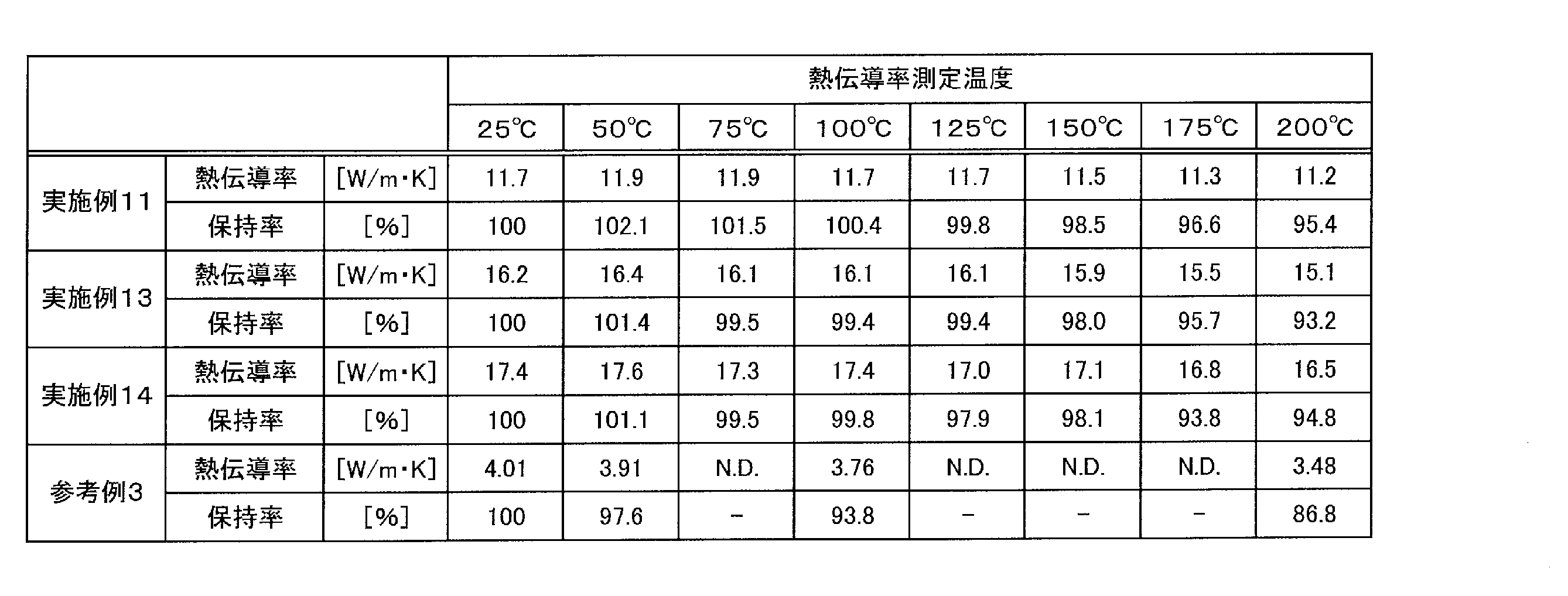
実施例7及び13と、比較例1及び2とを比較すると、実施例7及び13の熱伝導性樹脂シートを用いた放熱性回路基板は吸湿リフロー試験の前後でともに絶縁破壊電圧が40kV/mm以上を保っていた。また、吸湿リフロー試験後の熱伝導性樹脂シートと銅電極との界面を観察したところ、剥離や浮き、ボイドの形成は認められなかった。
一方、マトリクス樹脂として融点が224℃の結晶性熱可塑性樹脂であるPBTを用いた比較例1では、吸湿リフロー試験前の絶縁破壊電圧については、比較的高い値を得られているが、吸湿リフロー試験後の値は40kV/mmを下回っていた。また、吸湿リフロー試験後の熱伝導性樹脂シートと銅電極との界面を観察したところ、剥離や浮き、比較的顕著なボイドの発生が観察された。このことから、PBT等の融点が本発明の範囲より低い熱可塑性樹脂を用いた場合は、吸湿リフロー試験に耐えられず、金属板との積層体としたときに界面剥離が起こってしまうことがわかる。
また、マトリクス樹脂として熱硬化性樹脂であるエポキシ樹脂組成物を用いた比較例2では、吸湿リフロー試験前から絶縁破壊電圧が40kV/mmを下回る結果となった。その理由については判然としないが、塗工に用いた溶剤が樹脂組成物中に残留し、熱硬化時に発泡し、ボイドなどの欠陥部が形成されたこと等が原因と推定される。
さらに、吸湿リフロー試験後の熱伝導性樹脂シートと銅電極との界面を観察したところ、顕著な剥離や浮き、ボイドの発生が観察された。熱硬化性樹脂では、そのガラス転移温度を超えた温度での使用においても、三次元架橋構造を備えることにより、良好な耐熱性を示すと考えるのが一般的だが、上記吸湿リフロー試験は、熱硬化性樹脂に対しても苛酷な条件であると考えられる。
さらに、吸湿リフロー試験後の熱伝導性樹脂シートと銅電極との界面を観察したところ、顕著な剥離や浮き、ボイドの発生が観察された。熱硬化性樹脂では、そのガラス転移温度を超えた温度での使用においても、三次元架橋構造を備えることにより、良好な耐熱性を示すと考えるのが一般的だが、上記吸湿リフロー試験は、熱硬化性樹脂に対しても苛酷な条件であると考えられる。
以上のことから、本発明の熱伝導性樹脂シートは、マトリクス樹脂として300℃以上の融点を有する結晶性熱可塑性樹脂を用いることで吸湿リフロー耐性が良好となり、金属板との積層体としたときに熱膨張及び熱収縮による界面剥離が起こりにくいことがわかった。
また、実施例1~14と参考例1及び2とを比較すると、熱伝導性フィラーとして窒化ホウ素を用いる場合、平板状の窒化ホウ素一次粒子を用いるよりも窒化ホウ素凝集粒子を用いたほうが熱伝導率が高くなり、中でもキャベツ構造の窒化ホウ素凝集粒子を用いるよりもカードハウス構造の窒化ホウ素凝集粒子を用いたほうが熱伝導率が高くなった。
より具体的には、実施例9、実施例13及び参考例2を比べると、窒化ホウ素凝集粒子と平板状の窒化ホウ素一次粒子をそれぞれ同量用いた場合、窒化ホウ素凝集粒子を用いた実施例9及び実施例13の熱伝導性樹脂シートのほうが熱伝導率が高くなった。
また、実施例2、実施例8及び参考例1を比べると、平板状の窒化ホウ素一次粒子の含有量を増やしても、窒化ホウ素凝集粒子を用いた場合の熱伝導率には及ばなかった。
さらに、実施例1と実施例7、実施例2と実施例8、実施例9と実施例13をそれぞれ比較すると、キャベツ構造の窒化ホウ素凝集粒子とカードハウス構造の窒化ホウ素凝集粒子をそれぞれ同量用いた場合、カードハウス構造の窒化ホウ素凝集粒子を用いた実施例7、8及び13の熱伝導性樹脂シートの方が、熱伝導率が高くなった。
また、実施例2、実施例8及び参考例1を比べると、平板状の窒化ホウ素一次粒子の含有量を増やしても、窒化ホウ素凝集粒子を用いた場合の熱伝導率には及ばなかった。
さらに、実施例1と実施例7、実施例2と実施例8、実施例9と実施例13をそれぞれ比較すると、キャベツ構造の窒化ホウ素凝集粒子とカードハウス構造の窒化ホウ素凝集粒子をそれぞれ同量用いた場合、カードハウス構造の窒化ホウ素凝集粒子を用いた実施例7、8及び13の熱伝導性樹脂シートの方が、熱伝導率が高くなった。
以上のことから、本発明の熱伝導性樹脂シートは、熱伝導性フィラーとして窒化ホウ素凝集粒子を用いることで熱伝導率が向上し、その中でもカードハウス構造の窒化ホウ素凝集粒子を用いることで、熱伝導率がさらに向上することがわかった。
また、実施例11、13及び14と参考例3とを比較すると、実施例11、13及び14の熱伝導性樹脂シートは200℃での厚み方向の熱伝導率が25℃での厚み方向の熱伝導率の90%以上であったのに対し、参考例3のセラミック系材料は200℃での厚み方向の熱伝導率が25℃での厚み方向の熱伝導率の87%まで低下していた。
以上のことから、本発明の熱伝導性樹脂シートは、200℃においても高い熱伝導率を維持できていることがわかった。
また、実施例4と実施例5とを比較すると、溶融混練温度を395℃とした実施例5の熱伝導性樹脂シートのほうが熱伝導率が高くなった。これは、溶融混練温度を挙げることによりマトリクス樹脂の粘度が低下し、熱伝導性フィラーに加わる剪断応力が低下し、熱伝導性フィラーの破砕が抑制されたためであると考えられる。
さらに、実施例1~8と実施例9~14とを比較すると、加熱混練工程を経ずに、マトリクス樹脂の粉体原料と、熱伝導性フィラーの粉体とを室温で攪拌混合してプレス成型を行った実施例9~14の熱伝導性樹脂シートのほうが熱伝導率が高くなった。これは、熱伝導性フィラーが混練によって剪断破壊することが抑制されたためであると考えられる。
以上のことから、本発明の熱伝導性樹脂シートは、マトリクス樹脂の種類、熱伝導性フィラーの種類及び含有量、マトリクス樹脂と熱伝導性フィラーとの混合方法、加熱混練工程における条件等を変更することによって、熱伝導率を高くすることができることがわかった。
Claims (22)
- 300℃以上の融点を有する結晶性熱可塑性樹脂と熱伝導性フィラーとを含有する樹脂組成物からなり、当該熱伝導性フィラーが窒化ホウ素凝集粒子を含有する熱伝導性樹脂シート。
- 前記樹脂組成物が、前記結晶性熱可塑性樹脂を15質量%以上40質量%以下含有し、前記熱伝導性フィラーを60質量%以上85質量%以下含有する請求項1に記載の熱伝導性樹脂シート。
- 熱伝導性フィラー100質量%中に、前記窒化ホウ素凝集粒子を50質量%以上含有する請求項1又は2に記載の熱伝導性樹脂シート。
- 前記窒化ホウ素凝集粒子が、カードハウス構造を有するものである請求項1~3のいずれか1項に記載の熱伝導性樹脂シート。
- 25℃での厚み方向の熱伝導率が5.0W/m・K以上である、請求項1~4のいずれか1項に記載の熱伝導性樹脂シート、
- 25℃での厚み方向の熱伝導率が7.0W/m・K以上である、請求項1~4のいずれか1項に記載の熱伝導性樹脂シート。
- 200℃での厚み方向の熱伝導率が、前記25℃での厚み方向の熱伝導率の90%以上である、請求項5又は6に記載の熱伝導性樹脂シート。
- 熱伝導性樹脂シートの厚さが50μm以上300μm以下である、請求項1~7のいずれか1項に記載の熱伝導性樹脂シート。
- 300℃以上の融点を有する結晶性熱可塑性樹脂を15質量%以上40質量%以下の割合で含有し、且つ、熱伝導性フィラーを60質量%以上85質量%以下の割合で含有する樹脂組成物からなり、25℃での厚み方向の熱伝導率が5.0W/m・K以上である熱伝導性樹脂シート。
- 前記熱伝導性フィラー100質量%中に、窒化ホウ素を50質量%以上含有する請求項9に記載の熱伝導性樹脂シート。
- 前記窒化ホウ素が、窒化ホウ素一次粒子を凝集してなる窒化ホウ素凝集粒子を主成分とするものである請求項10に記載の熱伝導性樹脂シート。
- 前記窒化ホウ素凝集粒子が、カードハウス構造を有するものである請求項11に記載の熱伝導性樹脂シート。
- 前記結晶性熱可塑性樹脂が、ポリエーテルケトン系樹脂である請求項1~12のいずれか1項に記載の熱伝導性樹脂シート。
- 前記ポリエーテルケトン系樹脂が、ポリエーテルエーテルケトンである請求項13に記載の熱伝導性樹脂シート。
- 請求項1~14のいずれか1項に記載の熱伝導性樹脂シートの一方の表面に放熱用金属材料を積層した積層放熱シート。
- 請求項15に記載の積層放熱シートを有する放熱性回路基板。
- 前記熱伝導性樹脂シートの他方の表面に導電回路が積層される請求項16に記載の放熱性回路基板。
- 絶縁破壊電圧が40kV/mm以上である、請求項16又は17に記載の放熱性回路基板。
- 請求項16~18のいずれか1項に記載の放熱性回路基板を有するパワー半導体デバイス。
- 300℃以上の融点を有する結晶性熱可塑性樹脂からなる粉体と、熱伝導性フィラーの粉体とを混合して樹脂組成物を調製し、該樹脂組成物を加熱体でプレスしてシート成形することを含む、熱伝導性樹脂シートの製造方法。
- 前記樹脂組成物が、前記結晶性熱可塑性樹脂からなる粉体を15質量%以上40質量%以下含有し、前記熱伝導性フィラーの粉体を60質量%以上85質量%以下含有する請求項20に記載の熱伝導性樹脂シートの製造方法。
- 前記結晶性熱可塑性樹脂からなる粉体のD50に対する、前記熱伝導性フィラーの粉体のD50の比率(フィラー/熱可塑性樹脂)が0.3~6.0である請求項20又は21に記載の熱伝導性樹脂シートの製造方法。
Priority Applications (4)
| Application Number | Priority Date | Filing Date | Title |
|---|---|---|---|
| JP2021509433A JP7726065B2 (ja) | 2019-03-26 | 2020-03-24 | 熱伝導性樹脂シート、積層放熱シート、放熱性回路基板、及び、パワー半導体デバイス |
| CN202080022365.8A CN113573895A (zh) | 2019-03-26 | 2020-03-24 | 热传导性树脂片、层叠散热片、散热性电路基板及功率半导体器件 |
| EP20779966.9A EP3950328B1 (en) | 2019-03-26 | 2020-03-24 | Thermally conductive resin sheet, laminated heat dissipation sheet, heat dissipation circuit board, and power semiconductor device |
| US17/480,497 US20220002608A1 (en) | 2019-03-26 | 2021-09-21 | Thermally Conductive Resin Sheet, Laminated Heat Dissipation Sheet, Heat Dissipation Circuit Board, and Power Semiconductor Device |
Applications Claiming Priority (2)
| Application Number | Priority Date | Filing Date | Title |
|---|---|---|---|
| JP2019059173 | 2019-03-26 | ||
| JP2019-059173 | 2019-03-26 |
Related Child Applications (1)
| Application Number | Title | Priority Date | Filing Date |
|---|---|---|---|
| US17/480,497 Continuation US20220002608A1 (en) | 2019-03-26 | 2021-09-21 | Thermally Conductive Resin Sheet, Laminated Heat Dissipation Sheet, Heat Dissipation Circuit Board, and Power Semiconductor Device |
Publications (1)
| Publication Number | Publication Date |
|---|---|
| WO2020196477A1 true WO2020196477A1 (ja) | 2020-10-01 |
Family
ID=72610946
Family Applications (1)
| Application Number | Title | Priority Date | Filing Date |
|---|---|---|---|
| PCT/JP2020/012892 Ceased WO2020196477A1 (ja) | 2019-03-26 | 2020-03-24 | 熱伝導性樹脂シート、積層放熱シート、放熱性回路基板、及び、パワー半導体デバイス |
Country Status (6)
| Country | Link |
|---|---|
| US (1) | US20220002608A1 (ja) |
| EP (1) | EP3950328B1 (ja) |
| JP (1) | JP7726065B2 (ja) |
| CN (1) | CN113573895A (ja) |
| TW (1) | TW202100716A (ja) |
| WO (1) | WO2020196477A1 (ja) |
Cited By (2)
| Publication number | Priority date | Publication date | Assignee | Title |
|---|---|---|---|---|
| JP2023108214A (ja) * | 2022-01-25 | 2023-08-04 | 株式会社豊田中央研究所 | 複合材およびその製造方法 |
| WO2024204441A1 (ja) * | 2023-03-29 | 2024-10-03 | バンドー化学株式会社 | 熱伝導性組成物 |
Families Citing this family (5)
| Publication number | Priority date | Publication date | Assignee | Title |
|---|---|---|---|---|
| US20230317535A1 (en) * | 2022-03-31 | 2023-10-05 | Taiwan Semiconductor Manufacturing Company, Ltd. | Package structure and method for fabricating the same |
| IL292893A (en) * | 2022-05-09 | 2025-01-01 | Elbit Systems Ltd | Heat Dissipating Coating for Electronic Enclosures |
| TWI832534B (zh) * | 2022-11-03 | 2024-02-11 | 南亞塑膠工業股份有限公司 | 高導熱氟樹脂組成物及其製品 |
| TR2022018041A1 (tr) * | 2022-11-28 | 2024-06-21 | Eurotec Muehendislik Plastikleri Sanayi Ve Ticaret Anonim Sirketi | Isıl iletkenliği artırılmış polimer bazlı kompozit malzemeler. |
| US12249566B1 (en) * | 2023-08-21 | 2025-03-11 | Taiwan Semiconductor Manufacturing Co., Ltd. | 3DIC with gap-fill structures and the method of manufacturing the same |
Citations (11)
| Publication number | Priority date | Publication date | Assignee | Title |
|---|---|---|---|---|
| JPH0320354A (ja) | 1989-03-08 | 1991-01-29 | Mitsui Toatsu Chem Inc | 金属基板用フィルム |
| JPH07157569A (ja) | 1993-12-09 | 1995-06-20 | Mitsubishi Plastics Ind Ltd | 耐熱熱伝導性パツキン |
| JPH08283456A (ja) * | 1995-04-10 | 1996-10-29 | Otsuka Chem Co Ltd | 高熱伝導性樹脂組成物及びそのフィルム |
| JP2010137562A (ja) * | 2008-11-12 | 2010-06-24 | Nitto Denko Corp | 絶縁性熱伝導シートの製造方法、絶縁性熱伝導シート及び放熱部材 |
| JP2012255055A (ja) | 2011-06-07 | 2012-12-27 | National Institute Of Advanced Industrial Science & Technology | 無機有機複合組成物からなる複合材料及びその製造方法 |
| JP2013508491A (ja) * | 2009-10-21 | 2013-03-07 | エボニック デグサ ゲーエムベーハー | ポリアリーレンエーテルケトンより成るフィルム |
| WO2015033955A1 (ja) * | 2013-09-05 | 2015-03-12 | 三菱エンジニアリングプラスチックス株式会社 | 熱可塑性樹脂組成物、樹脂成形品、及びメッキ層付樹脂成形品の製造方法 |
| WO2015119198A1 (ja) | 2014-02-05 | 2015-08-13 | 三菱化学株式会社 | 窒化ホウ素凝集粒子、窒化ホウ素凝集粒子の製造方法、該窒化ホウ素凝集粒子含有樹脂組成物、成形体、及びシート |
| JP2015189823A (ja) * | 2014-03-27 | 2015-11-02 | 三菱化学株式会社 | 窒化ホウ素シート |
| JP2016098301A (ja) * | 2014-11-20 | 2016-05-30 | 三井・デュポンフロロケミカル株式会社 | 熱伝導性に優れた熱溶融性フッ素樹脂組成物、該組成物から製造された成形品および、その製造方法 |
| JP2017036415A (ja) | 2015-08-12 | 2017-02-16 | 三菱化学株式会社 | 放熱樹脂シート及び該放熱樹脂シートを含むデバイス |
Family Cites Families (6)
| Publication number | Priority date | Publication date | Assignee | Title |
|---|---|---|---|---|
| US7723419B1 (en) * | 2007-09-17 | 2010-05-25 | Ovation Polymer Technology & Engineered Materials, Inc. | Composition providing through plane thermal conductivity |
| JP2015168783A (ja) | 2014-03-07 | 2015-09-28 | 三井・デュポンフロロケミカル株式会社 | 高熱伝導性樹脂組成物 |
| JP6891461B2 (ja) * | 2016-11-18 | 2021-06-18 | 東洋インキScホールディングス株式会社 | 樹脂組成物 |
| JP7024213B2 (ja) | 2017-06-02 | 2022-02-24 | 日本ゼオン株式会社 | 熱伝導シート及びその製造方法 |
| US11572437B2 (en) * | 2017-06-12 | 2023-02-07 | Kaneka Corporation | Thermoplastic resin, thermoplastic resin composition, and heat conductive sheet |
| EP3667718B1 (en) | 2017-08-10 | 2021-12-22 | Denka Company Limited | Low-dielectric-constant thermally-conductive heat dissipation member |
-
2020
- 2020-03-24 WO PCT/JP2020/012892 patent/WO2020196477A1/ja not_active Ceased
- 2020-03-24 CN CN202080022365.8A patent/CN113573895A/zh active Pending
- 2020-03-24 EP EP20779966.9A patent/EP3950328B1/en active Active
- 2020-03-24 JP JP2021509433A patent/JP7726065B2/ja active Active
- 2020-03-26 TW TW109110190A patent/TW202100716A/zh unknown
-
2021
- 2021-09-21 US US17/480,497 patent/US20220002608A1/en not_active Abandoned
Patent Citations (11)
| Publication number | Priority date | Publication date | Assignee | Title |
|---|---|---|---|---|
| JPH0320354A (ja) | 1989-03-08 | 1991-01-29 | Mitsui Toatsu Chem Inc | 金属基板用フィルム |
| JPH07157569A (ja) | 1993-12-09 | 1995-06-20 | Mitsubishi Plastics Ind Ltd | 耐熱熱伝導性パツキン |
| JPH08283456A (ja) * | 1995-04-10 | 1996-10-29 | Otsuka Chem Co Ltd | 高熱伝導性樹脂組成物及びそのフィルム |
| JP2010137562A (ja) * | 2008-11-12 | 2010-06-24 | Nitto Denko Corp | 絶縁性熱伝導シートの製造方法、絶縁性熱伝導シート及び放熱部材 |
| JP2013508491A (ja) * | 2009-10-21 | 2013-03-07 | エボニック デグサ ゲーエムベーハー | ポリアリーレンエーテルケトンより成るフィルム |
| JP2012255055A (ja) | 2011-06-07 | 2012-12-27 | National Institute Of Advanced Industrial Science & Technology | 無機有機複合組成物からなる複合材料及びその製造方法 |
| WO2015033955A1 (ja) * | 2013-09-05 | 2015-03-12 | 三菱エンジニアリングプラスチックス株式会社 | 熱可塑性樹脂組成物、樹脂成形品、及びメッキ層付樹脂成形品の製造方法 |
| WO2015119198A1 (ja) | 2014-02-05 | 2015-08-13 | 三菱化学株式会社 | 窒化ホウ素凝集粒子、窒化ホウ素凝集粒子の製造方法、該窒化ホウ素凝集粒子含有樹脂組成物、成形体、及びシート |
| JP2015189823A (ja) * | 2014-03-27 | 2015-11-02 | 三菱化学株式会社 | 窒化ホウ素シート |
| JP2016098301A (ja) * | 2014-11-20 | 2016-05-30 | 三井・デュポンフロロケミカル株式会社 | 熱伝導性に優れた熱溶融性フッ素樹脂組成物、該組成物から製造された成形品および、その製造方法 |
| JP2017036415A (ja) | 2015-08-12 | 2017-02-16 | 三菱化学株式会社 | 放熱樹脂シート及び該放熱樹脂シートを含むデバイス |
Non-Patent Citations (2)
| Title |
|---|
| "Boron nitride that hasa card-house structure", CERAMICS, vol. 51, no. 10, 1 October 2016 (2016-10-01), JP , pages 717 - 718, XP009531006, ISSN: 0009-031X * |
| "Ceramics", vol. 43, 2008, CERAMIC SOCIETY OF JAPAN |
Cited By (4)
| Publication number | Priority date | Publication date | Assignee | Title |
|---|---|---|---|---|
| JP2023108214A (ja) * | 2022-01-25 | 2023-08-04 | 株式会社豊田中央研究所 | 複合材およびその製造方法 |
| JP7790168B2 (ja) | 2022-01-25 | 2025-12-23 | 株式会社豊田中央研究所 | 複合材およびその製造方法 |
| WO2024204441A1 (ja) * | 2023-03-29 | 2024-10-03 | バンドー化学株式会社 | 熱伝導性組成物 |
| JP7606050B1 (ja) * | 2023-03-29 | 2024-12-24 | バンドー化学株式会社 | 熱伝導性組成物 |
Also Published As
| Publication number | Publication date |
|---|---|
| JPWO2020196477A1 (ja) | 2020-10-01 |
| EP3950328B1 (en) | 2024-07-24 |
| US20220002608A1 (en) | 2022-01-06 |
| CN113573895A (zh) | 2021-10-29 |
| EP3950328A4 (en) | 2022-06-01 |
| TW202100716A (zh) | 2021-01-01 |
| JP7726065B2 (ja) | 2025-08-20 |
| EP3950328A1 (en) | 2022-02-09 |
Similar Documents
| Publication | Publication Date | Title |
|---|---|---|
| JP7726065B2 (ja) | 熱伝導性樹脂シート、積層放熱シート、放熱性回路基板、及び、パワー半導体デバイス | |
| JP5397476B2 (ja) | 樹脂組成物、樹脂シート、ならびに、樹脂硬化物およびその製造方法 | |
| CN110945647B (zh) | 导热片 | |
| JP5423455B2 (ja) | 熱伝導シート、その製造方法及び熱伝導シートを用いた放熱装置 | |
| CN107871721A (zh) | 导热性片材及其制备方法、以及半导体装置 | |
| JP7772151B2 (ja) | 樹脂組成物、樹脂硬化物および複合成形体 | |
| KR20110085991A (ko) | 열전도 시트, 그 제조방법 및 이것을 이용한 방열 장치 | |
| WO2008053843A1 (fr) | Feuille conductrice de chaleur, procédé de production de la feuille, et radiateur utilisant la feuille | |
| CN106103531A (zh) | 树脂组合物、树脂片、树脂片固化物、树脂片层叠体、树脂片层叠体固化物及其制造方法、半导体装置以及led装置 | |
| JP6981001B2 (ja) | 熱伝導シート及び熱伝導シートを用いた放熱装置 | |
| JP7581740B2 (ja) | 熱伝導性樹脂シート、積層放熱シート、放熱性回路基板およびパワー半導体デバイス | |
| EP4053213B1 (en) | Resin composition, cured product, composite molded body and semiconductor device | |
| JP7655035B2 (ja) | 熱伝導性樹脂組成物、熱伝導性樹脂シート、積層放熱シート、放熱性回路基板およびパワー半導体デバイス | |
| JP7643129B2 (ja) | 樹脂組成物、熱伝導性樹脂シート、積層放熱シート、放熱性回路基板及びパワー半導体デバイス | |
| WO2022255450A1 (ja) | 樹脂シート、積層体、及び半導体装置 | |
| JP7826781B2 (ja) | 熱伝導性樹脂シート、積層放熱シート、放熱性回路基板及びパワー半導体デバイス | |
| WO2022203031A1 (ja) | 熱伝導性樹脂組成物、熱伝導性樹脂シート、積層放熱シート、放熱性回路基板およびパワー半導体デバイス | |
| JP7806785B2 (ja) | 樹脂組成物、シート硬化物、複合成形体及び半導体デバイス | |
| JP6983345B1 (ja) | 熱伝導性シート、および電子機器 | |
| JP7383971B2 (ja) | 樹脂組成物、樹脂硬化物および複合成形体 | |
| JP7826782B2 (ja) | 熱伝導性樹脂シート、積層放熱シート、放熱性回路基板及びパワー半導体デバイス | |
| CN113227193A (zh) | 树脂组合物、该树脂组合物的制造方法、以及导热性片 | |
| JP7684915B2 (ja) | 熱伝導性シート、積層体、及び半導体装置 | |
| WO2025121381A1 (ja) | 樹脂シート及びその製造方法 |
Legal Events
| Date | Code | Title | Description |
|---|---|---|---|
| 121 | Ep: the epo has been informed by wipo that ep was designated in this application |
Ref document number: 20779966 Country of ref document: EP Kind code of ref document: A1 |
|
| ENP | Entry into the national phase |
Ref document number: 2021509433 Country of ref document: JP Kind code of ref document: A |
|
| NENP | Non-entry into the national phase |
Ref country code: DE |
|
| ENP | Entry into the national phase |
Ref document number: 2020779966 Country of ref document: EP Effective date: 20211026 |