WO2020196500A1 - Dispositif d'ouverture/fermeture d'un corps d'ouverture/fermeture - Google Patents
Dispositif d'ouverture/fermeture d'un corps d'ouverture/fermeture Download PDFInfo
- Publication number
- WO2020196500A1 WO2020196500A1 PCT/JP2020/012970 JP2020012970W WO2020196500A1 WO 2020196500 A1 WO2020196500 A1 WO 2020196500A1 JP 2020012970 W JP2020012970 W JP 2020012970W WO 2020196500 A1 WO2020196500 A1 WO 2020196500A1
- Authority
- WO
- WIPO (PCT)
- Prior art keywords
- carrier plate
- water
- opening
- guide rail
- closing body
- Prior art date
- Legal status (The legal status is an assumption and is not a legal conclusion. Google has not performed a legal analysis and makes no representation as to the accuracy of the status listed.)
- Ceased
Links
Images


Classifications
-
- E—FIXED CONSTRUCTIONS
- E05—LOCKS; KEYS; WINDOW OR DOOR FITTINGS; SAFES
- E05F—DEVICES FOR MOVING WINGS INTO OPEN OR CLOSED POSITION; CHECKS FOR WINGS; WING FITTINGS NOT OTHERWISE PROVIDED FOR, CONCERNED WITH THE FUNCTIONING OF THE WING
- E05F11/00—Man-operated mechanisms for operating wings, including those which also operate the fastening
- E05F11/38—Man-operated mechanisms for operating wings, including those which also operate the fastening for sliding windows, e.g. vehicle windows, to be opened or closed by vertical movement
- E05F11/382—Man-operated mechanisms for operating wings, including those which also operate the fastening for sliding windows, e.g. vehicle windows, to be opened or closed by vertical movement for vehicle windows
- E05F11/385—Fixing of window glass to the carrier of the operating mechanism
-
- B—PERFORMING OPERATIONS; TRANSPORTING
- B60—VEHICLES IN GENERAL
- B60J—WINDOWS, WINDSCREENS, NON-FIXED ROOFS, DOORS, OR SIMILAR DEVICES FOR VEHICLES; REMOVABLE EXTERNAL PROTECTIVE COVERINGS SPECIALLY ADAPTED FOR VEHICLES
- B60J1/00—Windows; Windscreens; Accessories therefor
- B60J1/08—Windows; Windscreens; Accessories therefor arranged at vehicle sides
- B60J1/12—Windows; Windscreens; Accessories therefor arranged at vehicle sides adjustable
- B60J1/16—Windows; Windscreens; Accessories therefor arranged at vehicle sides adjustable slidable
- B60J1/17—Windows; Windscreens; Accessories therefor arranged at vehicle sides adjustable slidable vertically
-
- E—FIXED CONSTRUCTIONS
- E05—LOCKS; KEYS; WINDOW OR DOOR FITTINGS; SAFES
- E05F—DEVICES FOR MOVING WINGS INTO OPEN OR CLOSED POSITION; CHECKS FOR WINGS; WING FITTINGS NOT OTHERWISE PROVIDED FOR, CONCERNED WITH THE FUNCTIONING OF THE WING
- E05F11/00—Man-operated mechanisms for operating wings, including those which also operate the fastening
- E05F11/38—Man-operated mechanisms for operating wings, including those which also operate the fastening for sliding windows, e.g. vehicle windows, to be opened or closed by vertical movement
- E05F11/48—Man-operated mechanisms for operating wings, including those which also operate the fastening for sliding windows, e.g. vehicle windows, to be opened or closed by vertical movement operated by cords or chains or other flexible elongated pulling elements, e.g. tapes
- E05F11/481—Man-operated mechanisms for operating wings, including those which also operate the fastening for sliding windows, e.g. vehicle windows, to be opened or closed by vertical movement operated by cords or chains or other flexible elongated pulling elements, e.g. tapes for vehicle windows
- E05F11/483—Man-operated mechanisms for operating wings, including those which also operate the fastening for sliding windows, e.g. vehicle windows, to be opened or closed by vertical movement operated by cords or chains or other flexible elongated pulling elements, e.g. tapes for vehicle windows by cables
- E05F11/486—Man-operated mechanisms for operating wings, including those which also operate the fastening for sliding windows, e.g. vehicle windows, to be opened or closed by vertical movement operated by cords or chains or other flexible elongated pulling elements, e.g. tapes for vehicle windows by cables with one cable connection to the window glass
-
- E—FIXED CONSTRUCTIONS
- E05—LOCKS; KEYS; WINDOW OR DOOR FITTINGS; SAFES
- E05Y—INDEXING SCHEME ASSOCIATED WITH SUBCLASSES E05D AND E05F, RELATING TO CONSTRUCTION ELEMENTS, ELECTRIC CONTROL, POWER SUPPLY, POWER SIGNAL OR TRANSMISSION, USER INTERFACES, MOUNTING OR COUPLING, DETAILS, ACCESSORIES, AUXILIARY OPERATIONS NOT OTHERWISE PROVIDED FOR, APPLICATION THEREOF
- E05Y2201/00—Constructional elements; Accessories therefor
- E05Y2201/60—Suspension or transmission members; Accessories therefor
- E05Y2201/622—Suspension or transmission members elements
- E05Y2201/64—Carriers
-
- E—FIXED CONSTRUCTIONS
- E05—LOCKS; KEYS; WINDOW OR DOOR FITTINGS; SAFES
- E05Y—INDEXING SCHEME ASSOCIATED WITH SUBCLASSES E05D AND E05F, RELATING TO CONSTRUCTION ELEMENTS, ELECTRIC CONTROL, POWER SUPPLY, POWER SIGNAL OR TRANSMISSION, USER INTERFACES, MOUNTING OR COUPLING, DETAILS, ACCESSORIES, AUXILIARY OPERATIONS NOT OTHERWISE PROVIDED FOR, APPLICATION THEREOF
- E05Y2201/00—Constructional elements; Accessories therefor
- E05Y2201/60—Suspension or transmission members; Accessories therefor
- E05Y2201/622—Suspension or transmission members elements
- E05Y2201/684—Rails; Tracks
-
- E—FIXED CONSTRUCTIONS
- E05—LOCKS; KEYS; WINDOW OR DOOR FITTINGS; SAFES
- E05Y—INDEXING SCHEME ASSOCIATED WITH SUBCLASSES E05D AND E05F, RELATING TO CONSTRUCTION ELEMENTS, ELECTRIC CONTROL, POWER SUPPLY, POWER SIGNAL OR TRANSMISSION, USER INTERFACES, MOUNTING OR COUPLING, DETAILS, ACCESSORIES, AUXILIARY OPERATIONS NOT OTHERWISE PROVIDED FOR, APPLICATION THEREOF
- E05Y2600/00—Mounting or coupling arrangements for elements provided for in this subclass
- E05Y2600/60—Mounting or coupling members; Accessories therefor
- E05Y2600/626—Plates or brackets
-
- E—FIXED CONSTRUCTIONS
- E05—LOCKS; KEYS; WINDOW OR DOOR FITTINGS; SAFES
- E05Y—INDEXING SCHEME ASSOCIATED WITH SUBCLASSES E05D AND E05F, RELATING TO CONSTRUCTION ELEMENTS, ELECTRIC CONTROL, POWER SUPPLY, POWER SIGNAL OR TRANSMISSION, USER INTERFACES, MOUNTING OR COUPLING, DETAILS, ACCESSORIES, AUXILIARY OPERATIONS NOT OTHERWISE PROVIDED FOR, APPLICATION THEREOF
- E05Y2800/00—Details, accessories and auxiliary operations not otherwise provided for
- E05Y2800/26—Form or shape
- E05Y2800/266—Form or shape curved
-
- E—FIXED CONSTRUCTIONS
- E05—LOCKS; KEYS; WINDOW OR DOOR FITTINGS; SAFES
- E05Y—INDEXING SCHEME ASSOCIATED WITH SUBCLASSES E05D AND E05F, RELATING TO CONSTRUCTION ELEMENTS, ELECTRIC CONTROL, POWER SUPPLY, POWER SIGNAL OR TRANSMISSION, USER INTERFACES, MOUNTING OR COUPLING, DETAILS, ACCESSORIES, AUXILIARY OPERATIONS NOT OTHERWISE PROVIDED FOR, APPLICATION THEREOF
- E05Y2800/00—Details, accessories and auxiliary operations not otherwise provided for
- E05Y2800/40—Physical or chemical protection
- E05Y2800/428—Physical or chemical protection against water or ice
-
- E—FIXED CONSTRUCTIONS
- E05—LOCKS; KEYS; WINDOW OR DOOR FITTINGS; SAFES
- E05Y—INDEXING SCHEME ASSOCIATED WITH SUBCLASSES E05D AND E05F, RELATING TO CONSTRUCTION ELEMENTS, ELECTRIC CONTROL, POWER SUPPLY, POWER SIGNAL OR TRANSMISSION, USER INTERFACES, MOUNTING OR COUPLING, DETAILS, ACCESSORIES, AUXILIARY OPERATIONS NOT OTHERWISE PROVIDED FOR, APPLICATION THEREOF
- E05Y2900/00—Application of doors, windows, wings or fittings thereof
- E05Y2900/50—Application of doors, windows, wings or fittings thereof for vehicles
- E05Y2900/53—Type of wing
- E05Y2900/55—Windows
Definitions
- the present invention relates to a switchgear opening / closing device that raises and lowers the switchgear via a carrier plate.
- a window regulator attached to a vehicle is known as an example of an opening / closing body opening / closing device that raises / lowers the opening / closing body to open / close the opening by moving a carrier plate that holds the opening / closing body.
- the window regulator moves the window glass held by the carrier plate by transmitting the driving force of the drive source to the carrier plate via a wire.
- the window regulator described in Patent Document 1 includes a carrier plate that holds a window glass, a guide rail that guides the movement of the carrier plate, a drive unit, a drum that rotates by the driving force of the drive unit, and one end of the drum. Is connected, and the other end is provided with a wire connected to the carrier plate.
- moisture such as rainwater that travels through the window glass of the vehicle and enters the inside of the door may adhere to the guide rail or the wire via the carrier plate.
- Moisture adhering to the guide rail or wire may flow downward along the guide rail or wire and reach the drive unit or drum, causing rust on them.
- the window regulator of Patent Document 1 is provided with an eave extending in the width direction of the carrier plate at the upper end of the carrier plate. Furthermore, the water flowing from the part where the eaves and the window glass are attached is discharged so as not to hit both the guide rail and the inner cable in the horizontal direction where the guide rail and the inner cable exist in the vertical downward direction.
- a guide unit is provided.
- An object of the present invention is to provide an opening / closing body opening / closing device that suppresses moisture such as rainwater that is transmitted from a holding opening / closing body and adheres to a carrier plate to adhere to a guide rail.
- the switchgear opening / closing device of the present invention A carrier plate that holds the opening and closing body, It has a guide rail that guides the movement of the carrier plate in the elevating direction of the opening / closing body.
- the carrier plate has a water holding portion at the upper end portion that holds water that reaches the upper end portion of the carrier plate from above.
- the water holding part is The water receiving part that receives the moisture that comes facing upward and It has an outflow suppressing portion provided with a suppressing surface for suppressing the outflow of the water to the guide rail facing the water receiving portion.
- the present invention it is possible to effectively prevent the moisture such as rainwater that is transmitted from the holding opening / closing body and adheres to the carrier plate from adhering to the guide rail.
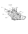
- FIG. 3 is a cross-sectional view taken along the line AA of FIG. It is a partial cross-sectional view which shows typically the water avoidance operation of a carrier plate. It is a figure which shows the outline of the flow of water when the permissible amount of water accumulated in a water holding part is exceeded.
- the switchgear opening / closing device of the present embodiment is a device that is attached to an attachment target having an opening and moves the carrier plate to open / close the opening by moving the opening / closing body held by the carrier plate up and down.
- the switchgear opening / closing device is fixed between the inner panel and the outer panel of the vehicle door, which is an example of an attachment target, and is a device for raising and lowering a window glass, which is an example of a switchgear, a so-called window. Described as a regulator.
- the switchgear opening / closing device is not limited to the window regulator but can be applied to other devices as long as it is a device that guides the movement of the carrier plate and raises and lowers the switchgear held by the carrier plate 20.
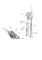
- FIG. 1 is an overall view of the switchgear opening / closing device as seen from the back side.
- the switchgear opening / closing device 1 shown in FIG. 1 moves the window glass, which is the opening / closing body W, held by the carrier plate 20 via the glass holder 13 up and down.
- the switchgear opening / closing device 1 can move the opening / closing body W, and by this movement, the window which is the opening is switched between the shielded state and the open state.
- the switchgear opening / closing device 1 is attached to the door panel of a vehicle, for example, by using a bracket (not shown) of the guide rail 30 and a fixing portion of the housing (not shown).
- the longitudinal direction of the guide rail 30 of the window regulator is the vertical direction, parallel to the glass surface of the window glass which is the opening / closing body W supported by the window regulator, and the vertical direction.
- the direction perpendicular to is described as the left-right direction.
- the switchgear opening / closing device 1 is driven by a carrier plate 20 provided with a glass holder 13 for connecting the window glass as the opening / closing body W, a guide rail 30, a direction changing portion 40 included in the upper joint member 41, a cable 60, and a drive.
- a portion 70, a drum member 80, and a drum housing 82 are provided.
- the upper joint member 41 is made of, for example, resin, and is connected to the upper end of the guide rail 30.
- the upper joint member 41 is provided with a fastening portion 41a that is fastened to the door of the vehicle by a fastening member (not shown) such as a bolt.
- the fastening portion 41a is provided with an insertion hole or the like through which the fastening member is inserted.
- the upper joint member 41 is fixed to the door of the vehicle by fastening the fastening portion 41a to the inner panel or the outer panel of the door of the vehicle.
- the upper joint member 41 has a direction changing portion 40 around which the ascending cable 61 is wound to change the moving direction of the ascending cable 61.
- the direction changing portion 40 is a guide groove provided in an arc shape, and the ascending cable 61 slides on the direction changing portion 40 to change the moving direction.
- the direction changing portion 40 converts the movement of pulling down one end side of the ascending cable 61 into the movement of pulling up the other end side.
- a pulley rotatably provided on the main body portion of the upper joint member 41 may be adopted.
- ⁇ Drum member 80> The drum member 80 is connected to the drive unit 70, and the cable 60 is wound around the drum member 80.
- the terminal member of the cable 60 is fixed to the drum member 80, and the cable 60 is wound up and the cable 60 is unwound.
- the drum member 80 has a locking portion (not shown) for accommodating the terminal member at the end of the cable 60, and is rotatably accommodated in the housing.
- the drum member 80 rotates in the forward direction and in the reverse direction by rotationally driving the drive unit 70.
- the drum member 80 is connected to the carrier plate 20 via a cable 60.
- the drum member 80 is made of, for example, resin or the like.
- the drum member 80 is connected to the cable ends of the ascending cable 61 and the descending cable 62, which are cables 60, and accommodates each of them.
- the drum member 80 winds up and unwinds the ascending cable 61 and the descending cable 62 by rotating in the forward direction and rotating in the reverse direction.
- the ascending cable 61 and the descending cable 62 are wound in opposite directions to each other.
- the drum member 80 winds the ascending cable 61 and pulls the ascending cable 61, or winds the descending cable 62 and pulls the descending cable 62.
- the drum member 80 of the present embodiment is connected to both the ascending cable 61 and the descending cable 62 at the lower end of the guide rail 30, and is rotated by the drive unit 70 via the cable 60. To move the carrier plate 20.
- the drum housing 82 is made of, for example, resin, and rotatably accommodates the drum member 80.
- a drive unit 70 is fixed to the drum housing 82, and a lower end portion of the guide rail 30 is connected to the drum housing 82, and also has a fastening portion to be fastened to the door of the vehicle.
- the drive unit 70 connects to the drum member 80 and supplies a driving force for rotating the drum member 80 to the drum member 80.
- the drive unit 70 is connected to a drive source such as a power supply for driving the drum member 80 so that the drum member 80 is rotated by driving the drive source.
- the drive unit 70 rotates the drum member 80 by the energy of the drive source or the like, and winds up the cable 60 or unwinds the cable 60.
- the drive unit 70 includes, for example, a motor driven by turning the power on and off, and rotates the connected drum member 80.
- the drive unit 70 is housed in a motor housing and is fixed to a substrate to be mounted such as a door via the motor housing.
- the motor housing is fixed to the drum housing 82.
- the drive unit 70 is arranged at the lower end of the door panel in the door panel.
- the drive unit 70 of the present embodiment is a motor that is electrically driven by the current supplied from the battery. It is desirable that the motor of the drive unit 70 has a so-called clutch function that can lock the output shaft at a predetermined rotation angle.
- the drive unit 70 fits the motor shaft into the central portion of the drum member 80, and rotates the drum member 80 by the rotation of the motor shaft.
- the motor and the drum member 80 transmit the rotational motion of the motor to the drum member 80 via a power transmission unit such as a worm gear.
- the motor which is the drive unit 70, is rotationally driven in the forward direction and the reverse direction, whereby the drum member 80 rotates in the forward direction and the reverse direction.
- the drive unit 70 and the drum member 80 are arranged on the lower end side of the guide rail 30, but the present invention is not limited to this.
- the drive unit 70 and the drum member 80 may be arranged at any position as long as the carrier plate 20 can be raised and lowered via the cable 60, and the cable 60 may be arranged in any position.
- a drum member 80 rotated by the drive unit 70 is provided at a height between the upper end position and the lower end position, and the carrier plate 20 is raised via a cable 60 that is wound up and unwound from the drum member 80 at this position. It may be configured to be lowered.
- ⁇ Cable 60> The end of the cable 60 is connected to the carrier plate 20.
- the cable 60 is wound and unwound by the rotation of the drum member 80.
- the cable 60 operates the carrier plate 20 to move it.
- the cable 60 is locked to the drum member 80 and the carrier plate 20 by the terminal members at both ends. In these locking structures, even when the drum member 80 is rotated, any way the terminal members at both ends are engaged as long as they are engaged so as not to be disengaged from the drum member 80 and the carrier plate 20, respectively. Good.
- the cable 60 has an ascending cable 61 and a descending cable 62.
- One end of the ascending cable 61 is connected to the drum member 80, the middle portion is hung on the direction changing portion 40 of the upper joint member 41, and the other end is connected to the carrier plate 20.
- the drum member 80 rotates in the direction of winding the ascending cable 61
- the ascending cable 61 is pulled and the carrier plate 20 is pulled up via the direction changing portion 40.
- One end of the lowering cable 62 is connected to the drum member 80, and the other end is connected to the carrier plate 20.
- the lowering cable 62 is pulled and the carrier plate 20 is pulled down.
- the guide rail 30 guides the movement of the carrier plate 20 in the elevating direction of the opening / closing body W.
- the guide rail 30 is a rail that extends long in the moving direction of the carrier plate 20, and supports the carrier plate 20 so as to be movable along an elevating path.
- the guide rail 30 is provided on the vehicle door corresponding to the vertical locus of the opening / closing body W, and is provided so as to be inclined toward the rear side of the vehicle with respect to the vertical direction of the vehicle, for example.
- the guide rail 30 is typically composed of a metal plate and has a bent shape extending along the longitudinal direction of the metal plate.
- the guide rails 30 are provided on both sides of the concave guide portion main body 32 having a U-shaped cross section (see FIG. 3) and the guide portion main body 32 in the width direction, and are carriers. It has a guide portion 32c that slidably engages with the plate 20.
- the guide portion main body 32 has a convex shape on one surface (referred to as “front surface 32a” for convenience) and the other surface (for convenience, “back surface 32b”) when viewed from the side. It is configured in a curved shape with a concave side.
- the carrier plate 20 engages with the guide portion 32c on the surface 32a side of the guide rail 30, that is, on the convex surface side, and is slidably attached to the guide portion main body 32.
- Opening / closing body W is connected to the carrier plate 20 and moves up and down by moving the carrier plate 20 to open / close a predetermined opening (for example, an opening provided in the door body).
- the opening / closing body W switches between a shielded state of the opening and an open state.
- the opening / closing body W is a window glass.
- the window glass may be slid with respect to a door sash that defines an opening (not shown) so as to be supported by the door sash.
- the carrier plate 20 is guided to the position on the upper end side of the guide rail 30 to shield the opening, and the carrier plate 20 is guided from the position on the upper end side to the position on the lower end side of the guide rail 30.
- the opening is opened according to the above.
- the opening / closing body W is moved by the carrier plate 20 which is moved by winding out the cable 60.
- the opening / closing body W is a window glass, but for example, a panel made of metal, resin, or the like may be used in addition to glass.
- the carrier plate 20 shown in FIGS. 1 and 2 is connected to the opening / closing body W, and its movement is guided by the guide rail 30.
- the carrier plate 20 is connected via a glass holder 13 attached to the upper end portion 20b.
- the carrier plate 20 moves up and down while holding the opening / closing body W.
- the carrier plate 20 moves between an upper position in which the window is completely shielded by the opening / closing body W and closed, and a lower position in which the window is fully opened.
- the carrier plate 20 moves downward from the state in which the window is closed to the open state, the carrier plate 20 moves into the door (not shown) together with the opening / closing body W.
- the carrier plate 20 moves on the surface 32a of the curved guide rail 30 by the drive of the drive unit 70, and changes its posture according to the curvature of the guide rail 30.
- the carrier plate 20 can be moved on the surface 32a of the guide rail 30 in a state of being connected to the lower side of the opening / closing body W.
- the carrier plate 20 has end accommodating portions 21 and 22 accommodating the end portions of the cable 60.
- the carrier plate 20 has a plate-shaped plate body 20a having a predetermined thickness, and the end accommodating portion is on the back surface side of the plate body 20a, that is, on the surface side facing the surface 32a of the guide rail 30. 21 and 22 are provided.
- the ascending cable 61 and the descending cable 62 are formed by an end portion of each cable and a terminal member formed of metal.
- the end accommodating portions 21 and 22 include an end accommodating portion 21 accommodating the terminal member 612 of the ascending cable 61 for raising the carrier plate 20, and the terminal member 622 of the lowering cable 62 for lowering the carrier plate 20. It has an end accommodating portion 22 for accommodating.
- 62 is derived from the end accommodating portions 21 and 22.
- the carrier plate 20 is fitted to the guide rail 30 on the back surface side of the plate main body 20a, so that the carrier plate 20 is vertically moved to the guide rail 30 in a state where the movement in the left-right direction is restricted by the guide rail 30. It is provided so as to be slidable.
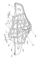
- FIG. 3 is a front view showing the carrier plate 20 of the switchgear opening / closing device 1 according to the embodiment of the present invention
- FIG. 4 is a cross-sectional view taken along the line AA of FIG.
- the carrier plate 20 has mounting portions 23a and 23b, a water holding portion 25, and a drainage portion 28.
- the carrier plate 20 is configured so that the water holding portion 25 provided at the upper end portion 20b prevents the water arriving at the upper end portion 20b from flowing out to the guide rail 30 side (water avoidance).
- the upper end portion 20b is located above the fitting portion of the plate body 20a with the end accommodating portions 21, 22 and the guide rail 30.
- the upper end portion 20b prevents moisture from above from directly reaching the fitting portion with the end accommodating portions 21, 22 and the guide rail 30.
- the shape of the plate body 20a can be changed at any time according to the shapes of the guide rail 30 and the opening / closing body W as long as the upper end portion 20b has the water holding portion 25.
- the mounting portions 23a and 23b and the water holding portion 25 are provided on the upper end portion 20b side of the plate body 20a.
- the drainage portion 28 is provided at the lower end portion and one side portion of the plate main body 20a in addition to the upper end portion 20b.
- a glass holder 13 connected to the opening / closing body W is attached to the attachment portions 23a and 23b.
- the mounting portions 23a and 23b refer to a wall portion that extends above the glass holder 13 and is erected, and the wall portion is provided with mounting holes that open in the thickness direction of the plate body 20a, respectively. There is. Opening and closing body W via fastening members such as screws and bolts inserted into these mounting holes
- Each of the glass holders 13 attached to the lower side is rotatably attached (see FIG. 1).
- the mounting portions 23a and 23b are arranged at the upper end portions 20b so as to be separated from each other at a predetermined interval in a direction intersecting the moving direction, and are provided in the width direction of the guide rail 30 in the present embodiment.
- the mounting portions 23a and 23b are arranged on one side and the other side in the width direction of the guide rail 30 in a state of being slidably engaged with the guide rail 30, and are more than the edge portion in the width direction of the guide rail 30, respectively.
- the plate body 20a is provided so as to be separated from the outside.
- the mounting portions 23a and 23b may be provided with stepped portions on a plane extending in the horizontal direction on the lower side of the standing wall portion.
- the water holding portion 25 is provided on the upper end portion 20b of the carrier plate 20.
- the water holding portion 25 holds the water that reaches the upper end portion 20b of the carrier plate 20 from above the carrier plate 20.
- the water holding portion 25 holds the water reaching the upper end portion 20b to prevent the water from being transmitted to the guide rail 30.
- the water that reaches the upper end 20b of the carrier plate 20 from above may be any water as long as it reaches the upper end 20b.
- the moisture arriving at the upper end portion 20b is, for example, a liquid such as rainwater, specifically, when there is rainwater transmitted through the opening / closing body W, rainwater transmitted from the opening / closing body W through the glass holder 13, or a sash. , Sash, opening / closing body W, and rainwater transmitted through the glass holder 13.
- the liquid may be a liquid such as car wash water instead of rainwater.
- the water holding portion 25 is provided at a position below the opening / closing body W. In particular, the water holding portion 25 is preferably provided at the position of the carrier plate 20 so that the water adhering to the opening / closing body W reaches the water holding portion 25 directly or via the glass holder 13.
- the water holding portion 25 is provided between the mounting portions 23a and 23b at the upper end portion 20b.
- the water holding portion 25 is connected to the drainage portion 28 (28a, 28b) via the connecting portion 281. In the present embodiment, the water holding portion 25 is further connected to the mounting portions 23a and 23b via the drainage portions 28 (28a and 28b).
- the water receiving portion 26 is provided in a shape that receives moisture at the upper end portion 20b, and receives the incoming moisture facing upward.
- the water holding portion 25 has a water receiving portion 26, a runoff suppressing portion 27, and an extending surface 29.
- the water holding portion 25 may have a downwardly convex bottom surface, and by having the outflow suppressing portion 27 and the extending surface 29, it is possible to receive more water than the horizontal plane.
- the water receiving portion 26 is formed so that the carrier plate 20 is located at a position on the upper end side of the guide rail 30 and has a concave shape that opens upward when the opening is closed by the opening / closing body W.
- the outflow suppressing unit 27 suppresses the outflow of water from the back surface side of the carrier plate 20, that is, the guide rail 30 side.
- the outflow suppression unit 27 has a suppression surface 271 that faces the water receiving unit 26 and suppresses the outflow of water to the guide rail 30.
- the outflow control unit 27 is erected on the guide rail 30 side of the water receiving unit 26.
- the outflow control portion 27 prevents the water received by the water receiving portion 26 from flowing to the guide rail 30 side at the upright portion of the water receiving portion 26, that is, the joint portion with the water receiving portion 26.
- the restraining surface 271 is formed of any shape such as a curved surface, a flat surface, or an uneven surface as long as it faces the water receiving portion 26 and suppresses the outflow of water to the guide rail 30. May be good.
- the restraining surface 271 functions as the surface of the outflow suppressing portion 27, and is partitioned into a plurality of portions by a plurality of partition wall portions 272 extending in the vertical direction and a wall portion serving as a connecting portion 281. It is provided in a state.
- the water holding portion 25 is the carrier plate 20 from above. Any configuration may be used as long as it has a function of retaining water reaching the upper end portion 20b. For example, even when the carrier plate 20 is located at the center or the lower end of the guide rail 30, it may be configured to store the water that reaches the upper end 20b.
- the water holding portion 25 is configured by being partitioned by the partition wall portion 272, and has a plurality of recesses arranged in the width direction of the carrier plate 20, but is not limited to this configuration.
- the carrier plate 20 is provided with an outflow suppressing portion 27 on the guide rail side of the water holding portion 25.
- the outflow control portion 27 is provided as an upright wall portion.
- the outflow suppressing unit 27 can easily prevent water from flowing out from the guide rail 30 side when the carrier plate 20 moves up and down.
- the water holding portion 25 has a water receiving portion 26 extending in the width direction of the carrier plate 20 at the upper end portion 20b, and a restraining surface 271 extending in the width direction of the carrier plate 20 and facing the water receiving portion 26. It may be configured to have an outflow control unit 27.
- the extending surface 29 may also be arranged over the entire width of the water receiving portion 26.
- the extending surface 29 is a surface facing upward, and extends to the side opposite to the guide rail side of the water receiving portion 26, has an upward slope with respect to the horizontal direction, and extends to the opposite side to the guide rail 30. ..
- the extending surface 29 is a guide rail from an edge portion opposite to the guide rail 30 on the surface of the upper end portion 20b which is the bottom surface of the water receiving portion 26, that is, the edge portion on the surface side of the carrier plate 20. It is provided so as to extend to the opposite side of 30.
- the extending surface 29 receives water from the water receiving portion 26 when the carrier plate 20 is located at the upper end of the guide rail 30, which is opposite to the guide rail 30 side, that is, the carrier plate 20. Prevents leakage to the surface side.
- the extension surface 29 is inclined downward due to the downward movement of the carrier plate 20 of the guide rail 30 (see FIG. 5).
- the extending surface 29 is provided so as to extend to the left and right of the upper end portion 20b.
- the extending surface 29 is a surface of the water receiving portion 26 opposite to the guide rail 30 side when the carrier plate 20 is located at the position on the upper end side of the guide rail 30 and the opening is closed by the opening / closing body W. It is arranged so as to extend from the side portion on the side to the bottom surface of the water receiving portion 26 on the opposite side of the guide rail with an upward slope.
- the water receiving portion 26 composed of a substantially flat flat portion extends in the width direction of the carrier plate 20.
- An outflow suppression portion 27 is provided at the edge of the water receiving portion 26 on the guide rail 30 side, and the suppression surface 271 and the water receiving portion 26, which are surfaces of the outflow suppression portion 27 facing the water receiving portion, are substantially abbreviated.
- the angle is formed so as to be 90 ° or an obtuse angle.
- the extending surface 29 provided on the edge of the water receiving portion 26 opposite to the guide rail 30 forms an obtuse angle with the flat portion of the water receiving portion 26.
- the water receiving portion 26 is sandwiched between the restraining surface 271 and the extending surface 29 of the outflow suppressing portion 27.
- Moisture on the water receiving portion 26 is suppressed from moving in the thickness direction of the carrier plate 20 by the suppressing surface 271 and the extending surface 29 of the outflow suppressing portion 27. While moving up and down along the guide rail 30, the water receiving portion 26 is displaced between a horizontal state and an inclined state in which the guide rail side is on the lower side, but between the water receiving portion 26 and the outflow suppressing portion 27. It is also possible to retain water between the extending surface 29 and the extending surface 29. Moisture held between the water receiving portion 26 and the outflow suppressing portion 27 and between the water receiving portion 26 and the extending surface 29 can be drained to a position away from the guide rail 30 by the draining portion 28. ..
- the drainage section 28 has a first drainage section 28a and a second drainage section 28b that discharge the water that reaches the carrier plate 20 to the side or the lower side of the carrier plate 20.
- the first drainage portion 28a and the second drainage portion 28b are arranged so as to sandwich the water holding portion 25 at the upper end portion 20b, and are each formed by an inclined surface.
- the first drainage portion 28a and the second drainage portion 28b may be an inclined surface, or may be a vertical surface along the extending direction of the guide rail 30, and may be on the lower side of the wall portion on which the mounting portions 23a and 23b are erected. May be provided so as to be connected to a provided step portion extending in the horizontal direction.
- the drainage portion 28 may be provided in a groove shape.
- the first drainage portion 28a is provided between the attachment portion 23a side and the water holding portion 25 side at the upper end portion 20b.
- the first drainage portion 28a has a V-shaped groove extending from the back surface side to the front surface side of the carrier plate 20.
- the V-shaped groove is formed from the first surface 282a and the first surface 282a which are substantially horizontal when the carrier plate 20 is located at the upper end side of the guide rail 30 and the opening is closed by the opening / closing body W. It is formed by a second surface 282b that is inclined so as to rise toward the back surface side. As a result, the water that reaches the first drainage portion 28a is guided by the V-shaped groove and drained to the surface side of the carrier plate 20.
- the second drainage portion 28b is formed by an inclined surface that slopes downward from the back surface side to the front surface side of the carrier plate 20 between the mounting portion 23b side and the water holding portion 25 side at the upper end portion 20b. ..
- the second drainage portion 28b becomes a substantially horizontal surface when the carrier plate 20 is located at the position on the upper end side of the guide rail 30 and the opening is closed by the opening / closing body W.
- the surface of the carrier plate is inclined from the back surface side to the front surface side.
- the water that reaches the second drainage portion 28b is drained to the surface side of the carrier plate 20 by the inclined surface of the second drainage portion 28b.
- the first drainage section 28a and the second drainage section 28b have connection sections 281 (281a, 281b) connected to the water holding section 25.
- the connecting portion 281a connects the water holding portion 25 and the first draining portion 28a so that the water that reaches the upper end portion 20b and is held by the water holding portion 25 can be discharged from the first draining portion 28a. ..
- the connection portion 281b connects the water holding portion 25 and the second drainage portion 28b so that the water that reaches the upper end portion 20b and is held by the water holding portion 25 can be discharged from the second drainage portion 28b. ..
- the connecting portions 281a and 281b are respectively erected from the water receiving portion 26 and joined to the water receiving portion 26 among the wall portions joined to the suppressing surface 271 of the outflow suppressing portion 27. It is a sloping lower part.
- the inclined lower portion is a portion of the water receiving portion 26 that is inclined upward from the front surface side to the back surface side.
- the carrier plate 20 is provided with a discharge gutter 28c over the lower edge portion of the plate body 20a and the side edge portion on the mounting portion 23b side.
- the discharge gutter 28c is provided in the plate body 20a of the carrier plate 20 in a rib shape protruding toward the surface side of the carrier plate 20, and the moisture from above is discharged from the carrier plate 20 along the extending direction of the discharge gutter 28c. It is guided downward and discharged so as not to come into contact with the guide rail 30 on the surface side of the carrier plate 20.
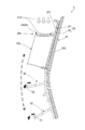
- FIG. 5 is a partial cross-sectional view schematically showing the water avoidance operation of the carrier plate.
- the carrier plate 20 in the switchgear opening / closing device 1, the carrier plate 20 is located at a position on the upper end side of the guide rail 30.
- the carrier plate 20 is formed so that the bottom surface of the water receiving portion 26 becomes horizontal when the opening is closed by the opening / closing body W, and the water receiving portion 26 is formed by the outflow suppressing portion 27 and the extending surface 29. It has a concave shape that opens upward.
- the water that reaches the upper end portion 20b from above the carrier plate 20 reaches the water receiving portion 26.
- the water receiving portion 26 can receive the water reaching the upper end portion 20b from above and prevent it from being transmitted to the back surface side of the carrier plate 20 by the outflow suppressing portion 27.
- the allowable amount of the water receiving portion 26 is exceeded.
- the water content exceeding the permissible amount is transmitted through the connecting portions 281a and 281b (arrow R1) and connected to the water holding portion 25. It flows to the outside of the carrier plate 20 by being guided by the drainage portions 28 (28a, 28b). As a result, water does not flow to the guide rail 30 side, and water does not propagate through the cable 60, the drive unit 70, and the drum member 80.
- the switchgear opening / closing device 1 of the present embodiment when water such as water droplets reaches the upper end portion 20b of the carrier plate 20, the water receiving portion 26 and the outflow suppressing portion 27 of the water holding portion 25 transfer the moisture. It can be held and prevented from flowing to the guide rail side.
- the upper surface (bottom surface of the water receiving portion 26) of the upper end portion 20b is provided so as to have an angle with respect to the horizontal plane, and the water receiving portion 26 and the water receiving portion 26 receive water. It can be stored in the corner with the outflow control unit 27 that is erected from. Further, when water accumulates in a predetermined amount or more between the water receiving portion 26 and the outflow suppressing portion 27, the moisture flows to the drainage portions 28a and 28b via the connecting portions 281a and 281b, so that the water flows out to the guide rail 30 side. It can be flowed sideways (see arrow R1) or forward of the carrier plate 20 without causing the carrier plate 20 to flow. That is, water flows in a direction away from the guide rail side, which is the back surface side of the carrier plate 20, and water can be prevented from flowing to the guide rail 30 and adhering to the guide rail 30.
- the carrier plate 20 when the carrier plate 20 is moved downward from the position on the upper end side of the guide rail 30, the carrier plate 20 has an upper end portion due to the shape of the curved guide rail 30, as shown by the broken line carrier plate 20 in FIG.
- the 20b moves so as to tilt downward.
- the water receiving portion 26 of the water holding portion 25 at the upper end portion 20b becomes a surface inclined toward the surface side, and the accumulated water flows to the surface side (see arrow R2 in FIG. 5) or sideways of the carrier plate 20. , Water does not flow to the guide rail 30 side.
- the carrier plate 20 can be moved to the position of the lower end of the guide rail 30 to open the open / close body without water flowing to the guide rail 30 side and adhering to the guide rail 30.
- the details specifically shown in the embodiment can be appropriately changed without departing from the spirit of the invention.
- the present invention can be used for a window regulator that raises and lowers the window glass of a vehicle such as an automobile.
- Switchgear 13 Glass holder 20 Carrier plate 20a Plate body 20b Upper end 21, 22 End accommodating 23a, 23b Mounting part 25 Water holding part 26 Water receiving part 27 Outflow control part 28 Draining part 28a First draining part (drainage) Department) 28b 2nd drainage section (drainage section) 28c Drain gutter 29 Extension surface 30 Guide rail 32 Guide part body 32a Front side 32b Back side 32c Guide part 40 Direction change part 41 Upper joint member 41a Fastening part 60 Cable 61 Lifting cable 62 Lowering cable 70 Drive part 80 Drum member 82 Drum housing 271 Suppressing surface 272 Partition wall part 281 Connection part 281a, 281b Connection part 282a First surface 282b Second surface 612, 622 Terminal member
Landscapes
- Engineering & Computer Science (AREA)
- Mechanical Engineering (AREA)
- Window Of Vehicle (AREA)
- Power-Operated Mechanisms For Wings (AREA)
Abstract
L'invention concerne un dispositif d'ouverture/fermeture d'un corps d'ouverture/fermeture qui a une plaque de support permettant de maintenir un corps d'ouverture/fermeture, et un rail de guidage permettant de guider le mouvement de la plaque de support dans la direction de montée/descente du corps d'ouverture/fermeture, sur l'extrémité supérieure, la plaque de support a une unité de retenue d'eau qui maintient l'eau qui atteint l'extrémité supérieure de la plaque de support par le dessus, et l'unité de maintien d'eau comporte une unité de réception d'eau qui fait face vers le haut et reçoit de l'eau entrante et une unité de suppression de débit sortant qui est pourvue d'une surface de suppression qui fait face à l'unité de réception d'eau et qui supprime l'écoulement d'eau s'écoulant vers le rail de guidage ; l'utilisation du dispositif d'ouverture/fermeture d'un corps d'ouverture/fermeture selon l'invention, permet d'éliminer de manière efficace la pluie ou d'autres eaux provenant d'un corps d'ouverture/fermeture maintenu par une plaque de support d'adhérer au rail de guidage.
Priority Applications (3)
| Application Number | Priority Date | Filing Date | Title |
|---|---|---|---|
| US17/442,257 US11884140B2 (en) | 2019-03-25 | 2020-03-24 | Opening/closing body opening/closing device |
| EP20777343.3A EP3951124A4 (fr) | 2019-03-25 | 2020-03-24 | Dispositif d'ouverture/fermeture d'un corps d'ouverture/fermeture |
| CN202080005513.5A CN112789388B (zh) | 2019-03-25 | 2020-03-24 | 开闭体开闭装置 |
Applications Claiming Priority (2)
| Application Number | Priority Date | Filing Date | Title |
|---|---|---|---|
| JP2019-056945 | 2019-03-25 | ||
| JP2019056945A JP6993375B2 (ja) | 2019-03-25 | 2019-03-25 | 開閉体開閉装置 |
Publications (1)
| Publication Number | Publication Date |
|---|---|
| WO2020196500A1 true WO2020196500A1 (fr) | 2020-10-01 |
Family
ID=72612005
Family Applications (1)
| Application Number | Title | Priority Date | Filing Date |
|---|---|---|---|
| PCT/JP2020/012970 Ceased WO2020196500A1 (fr) | 2019-03-25 | 2020-03-24 | Dispositif d'ouverture/fermeture d'un corps d'ouverture/fermeture |
Country Status (5)
| Country | Link |
|---|---|
| US (1) | US11884140B2 (fr) |
| EP (1) | EP3951124A4 (fr) |
| JP (1) | JP6993375B2 (fr) |
| CN (1) | CN112789388B (fr) |
| WO (1) | WO2020196500A1 (fr) |
Families Citing this family (1)
| Publication number | Priority date | Publication date | Assignee | Title |
|---|---|---|---|---|
| JP7431639B2 (ja) * | 2020-03-30 | 2024-02-15 | 株式会社アイシン | ワイヤ式レギュレータ |
Citations (4)
| Publication number | Priority date | Publication date | Assignee | Title |
|---|---|---|---|---|
| JPS593887A (ja) * | 1982-06-02 | 1984-01-10 | デイビイ・マツキ−(プ−ル)リミテツド | 金属帯板の横断磁束誘導ヒ−テイング |
| JP2556281Y2 (ja) * | 1991-08-09 | 1997-12-03 | 日本ケーブル・システム株式会社 | ウインドレギュレ−タ用キャリアプレ−ト |
| WO2015064266A1 (fr) * | 2013-10-30 | 2015-05-07 | 株式会社ハイレックスコーポレーション | Lève-glace |
| JP2017048517A (ja) * | 2015-08-31 | 2017-03-09 | いすゞ自動車株式会社 | キャリアプレート |
Family Cites Families (19)
| Publication number | Priority date | Publication date | Assignee | Title |
|---|---|---|---|---|
| US868413A (en) * | 1906-05-26 | 1907-10-15 | Judson M Cramer | Drip-trough. |
| US1954268A (en) * | 1930-08-05 | 1934-04-10 | Ternstedt Mfg Co | Weather strip window sash channel |
| JPS5864778U (ja) * | 1981-10-27 | 1983-05-02 | ダイキヨ−・ベバスト株式会社 | 開閉窓におけるガイドレ−ル防水構造 |
| JPS60115373U (ja) * | 1984-01-14 | 1985-08-05 | 日本ケ−ブル・システム株式会社 | ウインドレギユレ−タ用キヤリアプレ−ト |
| JPS61166719A (ja) * | 1985-01-16 | 1986-07-28 | Nissan Motor Co Ltd | 自動車用ドア構造 |
| US4962601A (en) * | 1989-10-11 | 1990-10-16 | Gold Peter N | Drainage guide for automobile window |
| JP3409926B2 (ja) * | 1994-03-15 | 2003-05-26 | アスモ株式会社 | ウインドウレギュレータ |
| JP3511433B2 (ja) * | 1995-06-30 | 2004-03-29 | アスモ株式会社 | ウインドウレギュレータ |
| US5791088A (en) * | 1996-10-25 | 1998-08-11 | Ford Global Technologies, Inc. | Weatherstrip apparatus for vehicle door window |
| JP4230405B2 (ja) * | 2004-04-20 | 2009-02-25 | 株式会社ハイレックスコ−ポレ−ション | キャリアプレートおよびそれを用いたウインドレギュレータ |
| ES2255393B1 (es) * | 2004-06-23 | 2007-03-16 | Melchor Daumal Castellon | Dispositivo de accionamiento de las ventanillas laterales posteriores de vehiculos descapotables. |
| JP2007162349A (ja) * | 2005-12-14 | 2007-06-28 | Aisin Seiki Co Ltd | 車両用ガラス移動装置 |
| US7555868B2 (en) * | 2006-06-26 | 2009-07-07 | Nissan Technical Center North America, Inc. | Window regulator lifter plate |
| US7861464B2 (en) * | 2009-02-04 | 2011-01-04 | Gm Global Technology Operations, Inc. | Vehicle window glass drip management |
| JP6067127B2 (ja) * | 2013-09-02 | 2017-01-25 | 本田技研工業株式会社 | 車両用ドア |
| EP3135517B2 (fr) * | 2015-07-31 | 2023-01-04 | AGC Inc. | Partie beltline d'automobile et structure d'isolation phonique et vitre de portière d'automobile |
| JP6742706B2 (ja) * | 2015-08-31 | 2020-08-19 | いすゞ自動車株式会社 | キャリアプレート |
| US10155436B2 (en) * | 2016-11-04 | 2018-12-18 | Ford Global Technologies, Llc | Motor vehicle door assembly with water management feature on window subassembly |
| DE112018003417T5 (de) * | 2017-07-03 | 2020-03-26 | AGC Inc. | Gürtellinienabschnitt-schallisolierstruktur für ein automobil und türscheibe für ein automobil |
-
2019
- 2019-03-25 JP JP2019056945A patent/JP6993375B2/ja active Active
-
2020
- 2020-03-24 US US17/442,257 patent/US11884140B2/en active Active
- 2020-03-24 EP EP20777343.3A patent/EP3951124A4/fr active Pending
- 2020-03-24 CN CN202080005513.5A patent/CN112789388B/zh active Active
- 2020-03-24 WO PCT/JP2020/012970 patent/WO2020196500A1/fr not_active Ceased
Patent Citations (4)
| Publication number | Priority date | Publication date | Assignee | Title |
|---|---|---|---|---|
| JPS593887A (ja) * | 1982-06-02 | 1984-01-10 | デイビイ・マツキ−(プ−ル)リミテツド | 金属帯板の横断磁束誘導ヒ−テイング |
| JP2556281Y2 (ja) * | 1991-08-09 | 1997-12-03 | 日本ケーブル・システム株式会社 | ウインドレギュレ−タ用キャリアプレ−ト |
| WO2015064266A1 (fr) * | 2013-10-30 | 2015-05-07 | 株式会社ハイレックスコーポレーション | Lève-glace |
| JP2017048517A (ja) * | 2015-08-31 | 2017-03-09 | いすゞ自動車株式会社 | キャリアプレート |
Non-Patent Citations (1)
| Title |
|---|
| See also references of EP3951124A4 * |
Also Published As
| Publication number | Publication date |
|---|---|
| EP3951124A4 (fr) | 2022-12-28 |
| US20220153094A1 (en) | 2022-05-19 |
| EP3951124A1 (fr) | 2022-02-09 |
| CN112789388A (zh) | 2021-05-11 |
| US11884140B2 (en) | 2024-01-30 |
| CN112789388B (zh) | 2022-09-23 |
| JP6993375B2 (ja) | 2022-01-13 |
| JP2020158984A (ja) | 2020-10-01 |
Similar Documents
| Publication | Publication Date | Title |
|---|---|---|
| JP6523962B2 (ja) | ウインドレギュレータ | |
| EP0619854B1 (fr) | Fenetre a cadre constitue de profiles extrudes | |
| EP1488944A1 (fr) | Module de support a fermeture etanche pour portes de vehicule et procede de montage dudit module | |
| JP6993375B2 (ja) | 開閉体開閉装置 | |
| US5902008A (en) | Drainage structure for use in sunroof apparatus | |
| JP2557981B2 (ja) | 自動車の滑り屋根及び滑りー揺動屋根 | |
| KR102053882B1 (ko) | 자동차용 도어 레귤레이터 | |
| CN110409950A (zh) | 对象物移动装置及窗玻璃升降装置 | |
| JP2021127580A (ja) | 昇降装置 | |
| EP3584397B1 (fr) | Rebord de fenêtre de drainage | |
| JP2021127579A (ja) | ドア構造 | |
| JP4226535B2 (ja) | ドアパネル構造およびウインドレギュレータ | |
| CN1792759B (zh) | 具有竖井门和门关闭装置的电梯设备 | |
| JP5077763B2 (ja) | 車両用ドア構造 | |
| JP4271786B2 (ja) | サンルーフのディフレクタ構造 | |
| KR101294080B1 (ko) | 차량용 도어 글라스 고정유닛 | |
| JP2012087456A (ja) | 外壁取り付けシャッターの防水構造 | |
| CN217048222U (zh) | 一种含有集成式遮阳帘支架的天窗框架 | |
| CN217048220U (zh) | 一种天窗框架的拉索密封结构 | |
| JP3647823B2 (ja) | 開閉窓 | |
| JP2605325Y2 (ja) | サンルーフのフレーム構造 | |
| WO2026023525A1 (fr) | Plaque de support et lève-vitre pourvu d'une plaque de support | |
| CN111497577A (zh) | 天窗结构 | |
| CN214034424U (zh) | 一种防腐蚀型电动天窗 | |
| KR200436145Y1 (ko) | 오버헤드 도어용 가이드 롤러의 위치조정구조 |
Legal Events
| Date | Code | Title | Description |
|---|---|---|---|
| 121 | Ep: the epo has been informed by wipo that ep was designated in this application |
Ref document number: 20777343 Country of ref document: EP Kind code of ref document: A1 |
|
| NENP | Non-entry into the national phase |
Ref country code: DE |
|
| ENP | Entry into the national phase |
Ref document number: 2020777343 Country of ref document: EP Effective date: 20211025 |