WO2020196521A1 - Dispositif laser - Google Patents
Dispositif laser Download PDFInfo
- Publication number
- WO2020196521A1 WO2020196521A1 PCT/JP2020/013017 JP2020013017W WO2020196521A1 WO 2020196521 A1 WO2020196521 A1 WO 2020196521A1 JP 2020013017 W JP2020013017 W JP 2020013017W WO 2020196521 A1 WO2020196521 A1 WO 2020196521A1
- Authority
- WO
- WIPO (PCT)
- Prior art keywords
- optical
- optical combiner
- laser
- combiner
- combiners
- Prior art date
- Legal status (The legal status is an assumption and is not a legal conclusion. Google has not performed a legal analysis and makes no representation as to the accuracy of the status listed.)
- Ceased
Links
Images
Classifications
-
- H—ELECTRICITY
- H01—ELECTRIC ELEMENTS
- H01S—DEVICES USING THE PROCESS OF LIGHT AMPLIFICATION BY STIMULATED EMISSION OF RADIATION [LASER] TO AMPLIFY OR GENERATE LIGHT; DEVICES USING STIMULATED EMISSION OF ELECTROMAGNETIC RADIATION IN WAVE RANGES OTHER THAN OPTICAL
- H01S5/00—Semiconductor lasers
- H01S5/40—Arrangement of two or more semiconductor lasers, not provided for in groups H01S5/02 - H01S5/30
- H01S5/4012—Beam combining, e.g. by the use of fibres, gratings, polarisers, prisms
-
- A—HUMAN NECESSITIES
- A61—MEDICAL OR VETERINARY SCIENCE; HYGIENE
- A61B—DIAGNOSIS; SURGERY; IDENTIFICATION
- A61B18/00—Surgical instruments, devices or methods for transferring non-mechanical forms of energy to or from the body
- A61B18/18—Surgical instruments, devices or methods for transferring non-mechanical forms of energy to or from the body by applying electromagnetic radiation, e.g. microwaves
- A61B18/20—Surgical instruments, devices or methods for transferring non-mechanical forms of energy to or from the body by applying electromagnetic radiation, e.g. microwaves using laser
- A61B18/22—Surgical instruments, devices or methods for transferring non-mechanical forms of energy to or from the body by applying electromagnetic radiation, e.g. microwaves using laser the beam being directed along or through a flexible conduit, e.g. an optical fibre; Couplings or hand-pieces therefor
- A61B18/24—Surgical instruments, devices or methods for transferring non-mechanical forms of energy to or from the body by applying electromagnetic radiation, e.g. microwaves using laser the beam being directed along or through a flexible conduit, e.g. an optical fibre; Couplings or hand-pieces therefor with a catheter
-
- H—ELECTRICITY
- H01—ELECTRIC ELEMENTS
- H01S—DEVICES USING THE PROCESS OF LIGHT AMPLIFICATION BY STIMULATED EMISSION OF RADIATION [LASER] TO AMPLIFY OR GENERATE LIGHT; DEVICES USING STIMULATED EMISSION OF ELECTROMAGNETIC RADIATION IN WAVE RANGES OTHER THAN OPTICAL
- H01S5/00—Semiconductor lasers
- H01S5/005—Optical components external to the laser cavity, specially adapted therefor, e.g. for homogenisation or merging of the beams or for manipulating laser pulses, e.g. pulse shaping
-
- H—ELECTRICITY
- H01—ELECTRIC ELEMENTS
- H01S—DEVICES USING THE PROCESS OF LIGHT AMPLIFICATION BY STIMULATED EMISSION OF RADIATION [LASER] TO AMPLIFY OR GENERATE LIGHT; DEVICES USING STIMULATED EMISSION OF ELECTROMAGNETIC RADIATION IN WAVE RANGES OTHER THAN OPTICAL
- H01S5/00—Semiconductor lasers
- H01S5/02—Structural details or components not essential to laser action
- H01S5/022—Mountings; Housings
- H01S5/0239—Combinations of electrical or optical elements
-
- A—HUMAN NECESSITIES
- A61—MEDICAL OR VETERINARY SCIENCE; HYGIENE
- A61B—DIAGNOSIS; SURGERY; IDENTIFICATION
- A61B18/00—Surgical instruments, devices or methods for transferring non-mechanical forms of energy to or from the body
- A61B2018/00571—Surgical instruments, devices or methods for transferring non-mechanical forms of energy to or from the body for achieving a particular surgical effect
- A61B2018/00577—Ablation
-
- A—HUMAN NECESSITIES
- A61—MEDICAL OR VETERINARY SCIENCE; HYGIENE
- A61B—DIAGNOSIS; SURGERY; IDENTIFICATION
- A61B18/00—Surgical instruments, devices or methods for transferring non-mechanical forms of energy to or from the body
- A61B18/18—Surgical instruments, devices or methods for transferring non-mechanical forms of energy to or from the body by applying electromagnetic radiation, e.g. microwaves
- A61B18/20—Surgical instruments, devices or methods for transferring non-mechanical forms of energy to or from the body by applying electromagnetic radiation, e.g. microwaves using laser
- A61B2018/2035—Beam shaping or redirecting; Optical components therefor
- A61B2018/20554—Arrangements for particular intensity distribution, e.g. tophat
-
- A—HUMAN NECESSITIES
- A61—MEDICAL OR VETERINARY SCIENCE; HYGIENE
- A61B—DIAGNOSIS; SURGERY; IDENTIFICATION
- A61B18/00—Surgical instruments, devices or methods for transferring non-mechanical forms of energy to or from the body
- A61B18/18—Surgical instruments, devices or methods for transferring non-mechanical forms of energy to or from the body by applying electromagnetic radiation, e.g. microwaves
- A61B18/20—Surgical instruments, devices or methods for transferring non-mechanical forms of energy to or from the body by applying electromagnetic radiation, e.g. microwaves using laser
- A61B18/22—Surgical instruments, devices or methods for transferring non-mechanical forms of energy to or from the body by applying electromagnetic radiation, e.g. microwaves using laser the beam being directed along or through a flexible conduit, e.g. an optical fibre; Couplings or hand-pieces therefor
- A61B2018/2205—Characteristics of fibres
- A61B2018/2211—Plurality of fibres
-
- A—HUMAN NECESSITIES
- A61—MEDICAL OR VETERINARY SCIENCE; HYGIENE
- A61B—DIAGNOSIS; SURGERY; IDENTIFICATION
- A61B18/00—Surgical instruments, devices or methods for transferring non-mechanical forms of energy to or from the body
- A61B18/18—Surgical instruments, devices or methods for transferring non-mechanical forms of energy to or from the body by applying electromagnetic radiation, e.g. microwaves
- A61B18/20—Surgical instruments, devices or methods for transferring non-mechanical forms of energy to or from the body by applying electromagnetic radiation, e.g. microwaves using laser
- A61B18/22—Surgical instruments, devices or methods for transferring non-mechanical forms of energy to or from the body by applying electromagnetic radiation, e.g. microwaves using laser the beam being directed along or through a flexible conduit, e.g. an optical fibre; Couplings or hand-pieces therefor
- A61B2018/2244—Features of optical fibre cables, e.g. claddings
-
- G—PHYSICS
- G02—OPTICS
- G02B—OPTICAL ELEMENTS, SYSTEMS OR APPARATUS
- G02B6/00—Light guides; Structural details of arrangements comprising light guides and other optical elements, e.g. couplings
- G02B6/24—Coupling light guides
- G02B6/42—Coupling light guides with opto-electronic elements
- G02B6/4201—Packages, e.g. shape, construction, internal or external details
- G02B6/4249—Packages, e.g. shape, construction, internal or external details comprising arrays of active devices and fibres
- G02B6/425—Optical features
-
- G—PHYSICS
- G02—OPTICS
- G02B—OPTICAL ELEMENTS, SYSTEMS OR APPARATUS
- G02B6/00—Light guides; Structural details of arrangements comprising light guides and other optical elements, e.g. couplings
- G02B6/24—Coupling light guides
- G02B6/42—Coupling light guides with opto-electronic elements
- G02B6/4201—Packages, e.g. shape, construction, internal or external details
- G02B6/4287—Optical modules with tapping or launching means through the surface of the waveguide
-
- H—ELECTRICITY
- H01—ELECTRIC ELEMENTS
- H01S—DEVICES USING THE PROCESS OF LIGHT AMPLIFICATION BY STIMULATED EMISSION OF RADIATION [LASER] TO AMPLIFY OR GENERATE LIGHT; DEVICES USING STIMULATED EMISSION OF ELECTROMAGNETIC RADIATION IN WAVE RANGES OTHER THAN OPTICAL
- H01S2301/00—Functional characteristics
- H01S2301/20—Lasers with a special output beam profile or cross-section, e.g. non-Gaussian
- H01S2301/206—Top hat profile
-
- H—ELECTRICITY
- H01—ELECTRIC ELEMENTS
- H01S—DEVICES USING THE PROCESS OF LIGHT AMPLIFICATION BY STIMULATED EMISSION OF RADIATION [LASER] TO AMPLIFY OR GENERATE LIGHT; DEVICES USING STIMULATED EMISSION OF ELECTROMAGNETIC RADIATION IN WAVE RANGES OTHER THAN OPTICAL
- H01S5/00—Semiconductor lasers
- H01S5/02—Structural details or components not essential to laser action
- H01S5/022—Mountings; Housings
- H01S5/0225—Out-coupling of light
- H01S5/02251—Out-coupling of light using optical fibres
-
- H—ELECTRICITY
- H01—ELECTRIC ELEMENTS
- H01S—DEVICES USING THE PROCESS OF LIGHT AMPLIFICATION BY STIMULATED EMISSION OF RADIATION [LASER] TO AMPLIFY OR GENERATE LIGHT; DEVICES USING STIMULATED EMISSION OF ELECTROMAGNETIC RADIATION IN WAVE RANGES OTHER THAN OPTICAL
- H01S5/00—Semiconductor lasers
- H01S5/40—Arrangement of two or more semiconductor lasers, not provided for in groups H01S5/02 - H01S5/30
- H01S5/4025—Array arrangements, e.g. constituted by discrete laser diodes or laser bar
Definitions
- the present invention relates to a laser device.
- a laser device in which a catheter is inserted into a patient's body and treatment is performed by irradiating a target portion such as an affected area with a laser beam from the tip of an optical fiber in the catheter.
- a beam having a high flatness of the beam profile of the laser light may be used.
- the flatness of the beam profile of the laser beam is simply referred to as "flatness of the laser beam”.
- Patent Document 1 As a technique for improving the flatness of such laser light, for example, in Patent Document 1, light waveguideed by a plurality of optical waveguides is input to an incident end of an optical transmitter, and the light is input to the incident end of the optical transmitter.
- a configuration for improving the flatness of a laser beam by confining it in an optical transmission region and transmitting the light is disclosed.
- Patent Document 2 discloses a configuration for converting a Gaussian beam having a multimode optical fiber output into a flat top beam.
- Patent Document 3 includes a beam shaping optical element that redistributes the light emitted by a high-intensity light source into an emitted light beam having a far-field beam cross-sectional profile having a spatially flat light intensity distribution. The configuration is disclosed.
- Patent Documents 1 to 3 have a problem that they cannot be used in a thin tube such as a medical catheter because the apparatus configuration is complicated or a large arrangement space is required.
- the present invention has been made in view of the above, and an object of the present invention is to provide a laser apparatus that is excellent in space saving and can improve the flatness of a laser beam.
- the laser apparatus includes one or more laser diodes and two or more optical combiners, and the output side of the laser diode is 1 It is characterized in that it is connected to the input side of one optical combiner, and the output side of the one optical combiner is connected to the input side of another optical combiner.
- the laser device is characterized in that the optical combiner is a multimode optical fiber input / output.
- the laser apparatus is characterized in that the optical combiner is a 2: 1 optical combiner.
- the laser apparatus is characterized in that it includes two of the optical combiners, and the output side of the first optical combiner is connected to the input side of the second optical combiner.
- the laser device includes the three optical combiners, the output side of the first optical combiner is connected to the input side of the second optical combiner, and the output side of the second optical combiner is , It is characterized in that it is connected to the input side of the third optical combiner.
- the laser device is characterized in that the laser diode has a multimode optical fiber output.
- the laser device is characterized in that it includes two or more of the laser diodes, and the laser diodes are connected to the input side of different optical combiners.
- the laser device is characterized in that the number of the laser diodes is smaller than the total number of input ports of the optical combiner.
- the laser device includes an asymmetric tap coupler, and the input side of the asymmetric tap coupler is connected to the output side of the optical combiner arranged at the last stage.
- the flatness of the laser beam can be improved without requiring a large space by cascading a plurality of optical combiners.
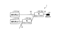
- FIG. 1 is a schematic view showing a configuration of a laser apparatus according to a first embodiment of the present invention.
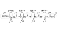
- FIG. 2 is an explanatory diagram for explaining the efficiency when a plurality of stages of optical combiners are connected.
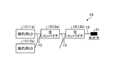
- FIG. 3 is a schematic view showing the configuration of the laser apparatus according to the second embodiment of the present invention.
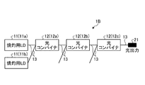
- FIG. 4 is a schematic view showing the configuration of the laser apparatus according to the third embodiment of the present invention.
- FIG. 5 is a schematic view showing the configuration of the laser apparatus according to the fourth embodiment of the present invention.
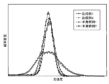
- FIG. 6 is a graph for explaining the relationship between the number of ablation laser diodes and optical combiners and the flatness of the laser beam in a laser apparatus in which optical combiners are cascaded in an embodiment of the present invention. is there.
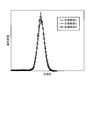
- FIG. 7 is a graph for explaining the relationship between the number of ablation laser diodes and optical combiners and the flatness of the laser beam in a laser apparatus in which optical combiners are cascaded in an embodiment of the present invention
- the laser apparatus according to the present invention includes one or more laser diodes for ablation (hereinafter referred to as "LD for ablation”) and two or more optical combiners, and the optical combiners are connected in series (cascade connection). It is characterized by being done.
- LD for ablation laser diodes for ablation
- optical combiners are connected in series (cascade connection). It is characterized by being done.
- the laser apparatus 1 As shown in FIG. 1, the laser apparatus 1 according to the present embodiment is arranged between two ablation LDs 11a and 11b, two optical combiners 12a and 12b, and ablation LDs 11a and 11b and an optical combiner 12a and 12b.
- the optical fiber 13 is provided.
- LD11 for ablation when a plurality of LDs for ablation are collectively referred to as "LD11 for ablation”, and when a plurality of optical combiners are collectively referred to, the term "optical combiner 12" is used.
- the ablation light output from the ablation LD11 is light in a wavelength band called a so-called "living body window", that is, light in a wavelength band of 600 nm to 1500 nm. ..
- the output of the ablation LD11 is set to, for example, 0.1 W or more.
- the ablation LD11s may be connected in series, for example, and may be configured to supply a common current from the same power source, or may be configured to supply different currents from different power sources. When the current of each ablation LD11 is supplied from a separate power source, there is an advantage that the mixing ratio of the laser beam of each ablation LD11 can be changed.
- the ablation LD11a is connected to the input side of the optical combiner 12b via an optical fiber 13. Further, the ablation LD11b is connected to the input side of the optical combiner 12a via the optical fiber 13.
- the optical fiber 13 used as the output port of the ablation LD 11 is a multimode optical fiber or a single mode optical fiber.
- the length of the optical fiber 13 is, for example, about 1 m.
- the efficiency decreases as the number of cascade connection stages increases. Therefore, as shown in FIG. 1, the efficiency is improved by connecting the two LD11s for ablation to different optical combiners 12 and minimizing the number of LD11s for ablation connected to each optical combiner 12. The decrease can be suppressed. Further, when the two LD11s for ablation are connected to different optical combiners 12, the light in different propagation modes is mixed by the subsequent optical combiner 12, so that the flatness of the laser beam is improved.
- the number of LD11s for ablation is smaller than the total number of input ports of the optical combiner 12.
- the optical combiner 12 preferably has one or more input ports to which the cauterizing LD 11 is not connected.
- the "input port” means a port on the input side of the optical combiner 12 other than the port connected to another optical combiner 12.
- the laser apparatus 1 shown in FIG. 1 is composed of the number of LD11s for ablation: 2, and the total number of input ports of the optical combiner 12: 3.
- the optical combiner 12 combines (synthesizes) a plurality of lights.
- the optical fiber 13 used as an input port and an output port of the optical combiner 12 is a multimode optical fiber.
- the optical fiber 13 is composed of, for example, a step index type optical fiber having a core diameter of 105 ⁇ m / clad diameter of 125 ⁇ m and having a coating such as an acrylate coating or a polyimide coating.
- the optical combiner 12 is an N: 1 optical combiner, preferably a 2: 1 optical combiner. Further, the optical combiner 12 is an end-couple type or side-couple type combiner. Further, each optical combiner 12 is installed on the same metal plate. This metal plate also functions as a heat radiating plate.
- the output side of the optical combiner 12a is connected to the input side of the optical combiner 12b via an optical fiber 13. Further, the output side of the optical combiner 12b is connected to the optical output unit 21 via the optical fiber 13.
- a light source other than the ablation LD11 for example, a monitor LD may be connected to an empty port of the optical combiner 12a that is not connected to the ablation LD11.
- the efficiency decreases as the number of cascade connection stages increases. Therefore, as shown in FIG. 1, the decrease in efficiency can be suppressed as much as possible by limiting the number of continuous connection stages of the optical combiner 12 to two. Further, the optical combiner 12 connected to the subsequent stage may generate heat as the efficiency decreases. Therefore, of the optical combiners 12a and 12b, a heat radiating mechanism (for example, a heat radiating plate) may be attached to the subsequent optical combiner 12b to suppress heat generation.
- a heat radiating mechanism for example, a heat radiating plate
- the optical output unit 21 outputs the light combined by the optical combiner 12b.
- the specific configuration of the light output unit 21 differs depending on the application of the laser device 1. For example, when the laser device 1 is used for laser treatment with a medical catheter, the light output unit 21 is composed of an optical probe or the like.
- the flatness of the laser beam can be improved without requiring a large space by cascading a plurality of optical combiners 12a and 12b. Further, according to the laser device 1, by connecting the two ablation LDs 11a and 11b to different optical combiners 12a and 12b, the light in different propagation modes is mixed by the subsequent optical combiner 12b. Therefore, the flatness of the laser beam is improved.
- the laser device 1 can save space as compared with the configuration disclosed in Patent Document 2.
- the laser apparatus 1A As shown in FIG. 3, the laser apparatus 1A according to the present embodiment is arranged between two ablation LDs 11a and 11b, two optical combiners 12a and 12b, and ablation LD11a and 11b and an optical combiner 12a and 12b.
- the optical fiber 13 is provided.
- the configurations of the ablation LD11, the optical combiner 12, the optical fiber 13, and the optical output unit 21 shown in FIG. 3 are the same as those in the first embodiment described above.
- the ablation LD11a and 11b are connected to the input side of the optical combiner 12a via the optical fiber 13. Further, the output side of the optical combiner 12a is connected to the input side of the optical combiner 12b via an optical fiber 13. Further, the output side of the optical combiner 12b is connected to the optical output unit 21 via the optical fiber 13. As described above, in the laser apparatus 1A according to the present embodiment, the two LD11a and 11b for ablation are connected to the input side of the same optical combiner 12a, and the optical combiner 12b arranged in the second stage is used for ablation. LD11 is not connected.
- the flatness of the laser beam can be improved without requiring a large space by cascading a plurality of optical combiners 12a and 12b.
- the laser apparatus 1B includes two ablation LDs 11a and 11b, three optical combiners 12a, 12b and 12c, and ablation LD11a and 11b and an optical combiner 12a, 12b and 12c. It is provided with an optical fiber 13 arranged between the two.
- the configurations of the ablation LD11, the optical combiner 12, the optical fiber 13, and the optical output unit 21 shown in FIG. 4 are the same as those in the first embodiment described above.
- the ablation LD11a and 11b are connected to the input side of the optical combiner 12a via the optical fiber 13. Further, the output side of the optical combiner 12a is connected to the input side of the optical combiner 12b via an optical fiber 13. Further, the output side of the optical combiner 12b is connected to the input side of the optical combiner 12c via an optical fiber 13. Further, the output side of the optical combiner 12c is connected to the optical output unit 21 via the optical fiber 13. As described above, in the laser apparatus 1B according to the present embodiment, the number of continuous connection stages of the optical combiner 12 is three.
- the flatness of the laser beam can be improved without requiring a large space by cascading a plurality of optical combiners 12a and 12b. Further, according to the laser apparatus 1B, by setting the number of continuous connection stages of the optical combiner 12 to three, each optical combiner 12 can excite a higher-order mode. Therefore, it is possible to obtain laser light having many higher-order modes as compared with the case where the number of continuous connection stages of the optical combiner 12 is two or less.
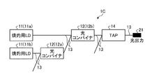
- the laser apparatus 1C As shown in FIG. 5, the laser apparatus 1C according to the present embodiment is arranged between the two ablation LDs 11a and 11b, the two optical combiners 12a and 12b, and the ablation LDs 11a and 11b and the optical combiners 12a and 12b.
- the optical fiber 13 and the asymmetric tap coupler 14 are provided.
- the configurations of the ablation LD11, the optical combiner 12, the optical fiber 13, and the optical output unit 21 shown in FIG. 4 are the same as those in the first embodiment described above.
- the ablation LD11a is connected to the input side of the optical combiner 12b via an optical fiber 13. Further, the ablation LD11b is connected to the input side of the optical combiner 12a via the optical fiber 13. Further, the output side of the optical combiner 12a is connected to the input side of the optical combiner 12b via an optical fiber 13. Further, the output side of the optical combiner 12b is connected to the input side of the asymmetric tap coupler 14 via the optical fiber 13.
- the output side of the asymmetric tap coupler 14 is connected to the optical output unit 21 via the optical fiber 13.
- the asymmetric tap coupler 14 is arranged in the optical combiner 12b arranged at the last stage.
- the synthesis ratio of the asymmetric tap coupler 14 for example, 99: 1, 95: 5, 90:10, 75:25 can be set. Further, in the asymmetric tap coupler 14 shown in FIG. 5, the ratio of the input port to the output port is 2: 1, but the ratio of the input port to the output port may be 1: 2 or 2: 2. ..
- An empty port of the asymmetric tap coupler 14 may be connected to, for example, a monitor PD, a light source that outputs a wavelength different from that of the ablation LD11, or the like.
- the flatness of the laser beam can be improved without requiring a large space by cascading a plurality of optical combiners 12a and 12b.
- the laser device 1C by connecting the asymmetric tap coupler 14 to the final stage optical combiner 12b, the high-order mode light excited by the optical combiner 12b is removed by the asymmetric tap coupler 14 and the tap port. A ring beam is formed from.
- the light of the main port is removed from the light of the higher order mode at a rate depending on the composition ratio, and the flatness is further improved.
- the present invention will be described in more detail with reference to examples.
- the relationship between the number of optical combiners and the flatness and intensity of laser light will be described with reference to Table 1.
- the half width of the intensity distribution in the beam profile of the laser beam hereinafter, simply referred to as "half width"
- the half width is defined as the laser. It is used as an index to judge the flatness of light.
- the half width of the laser beam is No. 4, No. 1, No. 2. No. It becomes smaller in the order of 3. That is, when the number of optical combiners is 0 to 2, the larger the number of optical combiners, the smaller the half width and the higher the flatness. On the other hand, when the number of optical combiners is 3, the half width is smaller than when the number of optical combiners is 0. This is because the optical combiner has a mode converter function that excites the light in the higher-order mode, and when the number of optical combiners exceeds a certain level, the proportion of the light in the higher-order mode increases and the flatness deteriorates. Is. The number of optical combiners whose flatness deteriorates also depends on the characteristics of the optical combiner.
- the maximum value of the light intensity of the laser beam is No. 1, No. 2.
- No. 3, No. It becomes smaller in the order of 4, that is, as the number of optical combiners increases.
- No. in Table 2 5 to 10 each show the following configurations.
- No. 5 Configuration No. in which only one LD for cauterization is arranged and no optical combiner is provided.
- 6 Configuration No. 2 in which two LDs for ablation are connected to one optical combiner.
- 7 Configuration No. in FIG. 8: Configuration No. 1 in FIG. 9: Configuration No. in FIG. 10: In FIG. 4, each of the cauterizing LD11b is connected to each input side of the optical combiner 12b.
- the half-value width of the laser beam is No. 9, No. 5, No. 6, No. 7, No. 8, No. It decreases in the order of 10. That is, the configuration in which the number of continuous connection stages of the optical combiner is three and the LD for cauterization is connected to the input side of the first and second stages of the optical combiner has the smallest half-value width and higher flatness.
- the maximum value of the light intensity of the laser beam is No. 5, No. 6, No. 8, No. 7, No. 10, No. It decreases in the order of 9. That is, the number of continuous connection stages of the optical combiner is three, and the light intensity is the smallest in the configuration in which two ablation LDs are connected to the input side of the first stage optical combiner (see FIG. 4).
- a light intensity map of laser light emitted from laser devices having a plurality of configurations is created, and light intensity data of each pixel of the light intensity map is aggregated to form a histogram.
- the graph shown in FIG. 7 was created.
- the horizontal axis of the figure is the light intensity of the laser beam, and the vertical axis is the probability density of the light intensity shown on the horizontal axis. Therefore, in the figure, the higher the graph is, the higher the flatness of the laser beam is, and the flatter the graph is, the lower the flatness of the laser beam is.
- Comparative Examples 1 and 2 and Examples 1 to 4 of FIGS. 6 and 7 show the following configurations, respectively.
- Comparative Example 1 Configuration in which only one ablation LD is arranged and does not have an optical combiner
- Comparative Example 2 Configuration in which two ablation LDs are connected to one optical combiner
- Example 1 Configuration of FIG.
- Invention Example 2 Configuration of FIG. 4
- Example 3 Configuration of FIG. 1
- Invention Example 4 Configuration of FIG.
- the configuration in which the number of optical combiners 12 cascaded is three has been described (see FIG. 4), but when it is desired to obtain laser light having more higher-order modes, light is used.
- the number of combiners 12 may be four or more.
- the present invention is suitable for application to a laser device that performs treatment by irradiating a target portion such as an affected area with a laser beam from the tip of an optical fiber in a catheter.
Landscapes
- Physics & Mathematics (AREA)
- Optics & Photonics (AREA)
- Electromagnetism (AREA)
- General Physics & Mathematics (AREA)
- Condensed Matter Physics & Semiconductors (AREA)
- Health & Medical Sciences (AREA)
- Surgery (AREA)
- Life Sciences & Earth Sciences (AREA)
- Engineering & Computer Science (AREA)
- Otolaryngology (AREA)
- Nuclear Medicine, Radiotherapy & Molecular Imaging (AREA)
- Biomedical Technology (AREA)
- Heart & Thoracic Surgery (AREA)
- Medical Informatics (AREA)
- Molecular Biology (AREA)
- Animal Behavior & Ethology (AREA)
- General Health & Medical Sciences (AREA)
- Public Health (AREA)
- Veterinary Medicine (AREA)
- Optical Couplings Of Light Guides (AREA)
- Semiconductor Lasers (AREA)
Abstract
Le but de la présente invention est de fournir un dispositif laser qui économise de l'espace et avec lequel il soit possible d'améliorer la planéité de la lumière laser. Un dispositif laser (1) comprend une ou plusieurs diodes laser (LD) de cautérisation (11) et au moins deux combineurs optiques (12). Le côté sortie d'une LD de cautérisation (11) est connecté au côté entrée d'un combineur optique (12), et le côté sortie du combineur optique (12) est connecté au côté entrée d'un autre combineur optique. Les combineurs optiques sont destinés à une entrée/sortie de fibre optique multimode et comprennent 2:1 combineurs optiques.
Priority Applications (3)
| Application Number | Priority Date | Filing Date | Title |
|---|---|---|---|
| CN202080022691.9A CN113615015B (zh) | 2019-03-27 | 2020-03-24 | 激光装置 |
| EP20777511.5A EP3952038B1 (fr) | 2019-03-27 | 2020-03-24 | Dispositif laser |
| US17/478,193 US12184038B2 (en) | 2019-03-27 | 2021-09-17 | Laser apparatus |
Applications Claiming Priority (2)
| Application Number | Priority Date | Filing Date | Title |
|---|---|---|---|
| JP2019060396A JP7203658B2 (ja) | 2019-03-27 | 2019-03-27 | レーザ装置 |
| JP2019-060396 | 2019-03-27 |
Related Child Applications (1)
| Application Number | Title | Priority Date | Filing Date |
|---|---|---|---|
| US17/478,193 Continuation US12184038B2 (en) | 2019-03-27 | 2021-09-17 | Laser apparatus |
Publications (1)
| Publication Number | Publication Date |
|---|---|
| WO2020196521A1 true WO2020196521A1 (fr) | 2020-10-01 |
Family
ID=72612017
Family Applications (1)
| Application Number | Title | Priority Date | Filing Date |
|---|---|---|---|
| PCT/JP2020/013017 Ceased WO2020196521A1 (fr) | 2019-03-27 | 2020-03-24 | Dispositif laser |
Country Status (5)
| Country | Link |
|---|---|
| US (1) | US12184038B2 (fr) |
| EP (1) | EP3952038B1 (fr) |
| JP (1) | JP7203658B2 (fr) |
| CN (1) | CN113615015B (fr) |
| WO (1) | WO2020196521A1 (fr) |
Families Citing this family (1)
| Publication number | Priority date | Publication date | Assignee | Title |
|---|---|---|---|---|
| CN112203609B (zh) * | 2018-06-01 | 2024-06-28 | 古河电气工业株式会社 | 检测系统、导管装置以及激光烧灼装置 |
Citations (5)
| Publication number | Priority date | Publication date | Assignee | Title |
|---|---|---|---|---|
| JP2005015722A (ja) | 2003-06-27 | 2005-01-20 | Gifu Prefecture | 木・竹酢液若しくはその製造方法及びその製造装置 |
| JP2007041342A (ja) * | 2005-08-04 | 2007-02-15 | Fujifilm Corp | 合波光源 |
| US20070092176A1 (en) * | 2003-07-18 | 2007-04-26 | Murphy Cary R | Remote location of active section of fiber in a multimode intrusion detection system |
| WO2017175391A1 (fr) * | 2016-04-08 | 2017-10-12 | オリンパス株式会社 | Dispositif d'éclairage et endoscope incluant celui-ci |
| US20180059323A1 (en) * | 2016-08-26 | 2018-03-01 | Nlight, Inc. | Splice with cladding mode light stripping |
Family Cites Families (17)
| Publication number | Priority date | Publication date | Assignee | Title |
|---|---|---|---|---|
| US4981138A (en) * | 1988-06-30 | 1991-01-01 | Yale University | Endoscopic fiberoptic fluorescence spectrometer |
| DE4238434A1 (de) * | 1992-04-16 | 1993-10-21 | Adlas Gmbh & Co Kg | Anordnung zur Bündelung und Einkopplung der von einem Halbleiterlaser erzeugten Strahlung in Lichtleitfasern |
| US6785440B1 (en) * | 1992-04-16 | 2004-08-31 | Coherent, Inc. | Assembly for focusing and coupling the radiation produced by a semiconductor laser into optical fibers |
| US6212310B1 (en) | 1996-10-22 | 2001-04-03 | Sdl, Inc. | High power fiber gain media system achieved through power scaling via multiplexing |
| JP4213402B2 (ja) * | 2002-05-23 | 2009-01-21 | 富士フイルム株式会社 | 集光レンズ、合波レーザー光源および露光装置 |
| US7403675B2 (en) | 2003-07-18 | 2008-07-22 | Network Integrity Systems Inc. | Method of high order mode excitation for multimode intrusion detection |
| US7403674B2 (en) | 2003-07-18 | 2008-07-22 | Network Integrity Systems Inc. | Intrusion detection system for a multimode optical fiber using a bulk optical wavelength division multiplexer for maintaining modal power distribution |
| EP1649310A4 (fr) | 2003-07-18 | 2009-04-08 | Network Integrity Systems Inc | Systeme de detection de l'intrusion d'une fibre optique multimode |
| JP2005157225A (ja) | 2003-11-06 | 2005-06-16 | Sumitomo Electric Ind Ltd | 光伝送体モジュール |
| DE102008052475A1 (de) * | 2008-10-20 | 2010-04-29 | Raab, Volker, Dr. | Polarisationskoppler |
| GB2490354A (en) * | 2011-04-28 | 2012-10-31 | Univ Southampton | Laser with axially-symmetric beam profile |
| EP2916759B1 (fr) * | 2012-11-09 | 2018-12-26 | Boston Scientific Scimed, Inc. | Outil laser chirurgical |
| US9560358B2 (en) * | 2013-07-22 | 2017-01-31 | Qualcomm Incorporated | Device and method for scalable coding of video information |
| EP3320396B1 (fr) | 2015-07-07 | 2019-01-02 | Lumileds Holding B.V. | Appareil electroluminescent |
| ITUB20155092A1 (it) | 2015-11-02 | 2017-05-02 | Quanta System Spa | Sistema laser per il trattamento selettivo dell'acne |
| KR102423775B1 (ko) * | 2016-08-30 | 2022-07-22 | 코닝 인코포레이티드 | 투명 재료의 레이저 가공 |
| JP7203031B2 (ja) * | 2017-01-25 | 2023-01-12 | ローレンス・リバモア・ナショナル・セキュリティー・エルエルシー | レーザシステム |
-
2019
- 2019-03-27 JP JP2019060396A patent/JP7203658B2/ja active Active
-
2020
- 2020-03-24 WO PCT/JP2020/013017 patent/WO2020196521A1/fr not_active Ceased
- 2020-03-24 EP EP20777511.5A patent/EP3952038B1/fr active Active
- 2020-03-24 CN CN202080022691.9A patent/CN113615015B/zh active Active
-
2021
- 2021-09-17 US US17/478,193 patent/US12184038B2/en active Active
Patent Citations (5)
| Publication number | Priority date | Publication date | Assignee | Title |
|---|---|---|---|---|
| JP2005015722A (ja) | 2003-06-27 | 2005-01-20 | Gifu Prefecture | 木・竹酢液若しくはその製造方法及びその製造装置 |
| US20070092176A1 (en) * | 2003-07-18 | 2007-04-26 | Murphy Cary R | Remote location of active section of fiber in a multimode intrusion detection system |
| JP2007041342A (ja) * | 2005-08-04 | 2007-02-15 | Fujifilm Corp | 合波光源 |
| WO2017175391A1 (fr) * | 2016-04-08 | 2017-10-12 | オリンパス株式会社 | Dispositif d'éclairage et endoscope incluant celui-ci |
| US20180059323A1 (en) * | 2016-08-26 | 2018-03-01 | Nlight, Inc. | Splice with cladding mode light stripping |
Non-Patent Citations (1)
| Title |
|---|
| See also references of EP3952038A4 |
Also Published As
| Publication number | Publication date |
|---|---|
| JP7203658B2 (ja) | 2023-01-13 |
| EP3952038A1 (fr) | 2022-02-09 |
| US12184038B2 (en) | 2024-12-31 |
| EP3952038B1 (fr) | 2024-05-01 |
| CN113615015B (zh) | 2024-04-30 |
| JP2020160310A (ja) | 2020-10-01 |
| EP3952038A4 (fr) | 2022-12-21 |
| CN113615015A (zh) | 2021-11-05 |
| US20220006266A1 (en) | 2022-01-06 |
Similar Documents
| Publication | Publication Date | Title |
|---|---|---|
| CN103597674B (zh) | 具有在亮度方面可调整的加工激光射束的激光加工系统 | |
| US20100010314A1 (en) | Endoscopic System Featuring Fiber-Pumped Fluorescent Illumination | |
| US20080219299A1 (en) | Optical fibre laser | |
| KR20120123011A (ko) | 단일 모드 고출력 파이버 레이저 시스템 | |
| CN107994448B (zh) | 一种白光激光器 | |
| CN110829166B (zh) | 一种具有光束净化功能的拉曼光纤放大器 | |
| CN106415359A (zh) | 照明装置、方法与医疗成像系统 | |
| JP2016002302A (ja) | 内視鏡光源装置 | |
| JP2012516040A (ja) | 二ステージ輝度変換装置 | |
| CN106159652A (zh) | 百瓦级双模式掺铥全光纤激光器 | |
| CN110829165A (zh) | 一种基于包层泵浦的大功率拉曼光纤放大器 | |
| WO2020196521A1 (fr) | Dispositif laser | |
| CN207009893U (zh) | 单管半导体激光器的多管合束装置 | |
| US11828455B2 (en) | Light source | |
| CN105790052A (zh) | 一种提高中红外超连续谱光源斜率效率和输出功率的方法 | |
| US10892603B2 (en) | Arrayed waveguide grating beam combiner | |
| CN1145051C (zh) | 宽面发射的激光二极管与单模光纤耦合器 | |
| CN206059905U (zh) | 半导体激光器 | |
| CN210779481U (zh) | 一种基于包层泵浦的大功率拉曼光纤放大器 | |
| CN205212176U (zh) | 一种可插拔跳线的半导体激光器 | |
| CN117192706B (zh) | 实现空心光束发射的超连续谱激光系统 | |
| CN105633775A (zh) | 一种高斜率效率、高功率的中红外超连续谱光源 | |
| CN108683063B (zh) | 一种二极管直接泵浦拉曼光纤激光器及其光谱合成方法 | |
| JP2012043849A (ja) | ファイバレーザデリバリシステム | |
| JP2012054349A (ja) | ファイバレーザ発振装置 |
Legal Events
| Date | Code | Title | Description |
|---|---|---|---|
| 121 | Ep: the epo has been informed by wipo that ep was designated in this application |
Ref document number: 20777511 Country of ref document: EP Kind code of ref document: A1 |
|
| NENP | Non-entry into the national phase |
Ref country code: DE |
|
| ENP | Entry into the national phase |
Ref document number: 2020777511 Country of ref document: EP Effective date: 20211027 |