WO2020196578A1 - Procédé de production d'une poudre sphérique solide et procédé de production d'un produit façonné - Google Patents
Procédé de production d'une poudre sphérique solide et procédé de production d'un produit façonné Download PDFInfo
- Publication number
- WO2020196578A1 WO2020196578A1 PCT/JP2020/013198 JP2020013198W WO2020196578A1 WO 2020196578 A1 WO2020196578 A1 WO 2020196578A1 JP 2020013198 W JP2020013198 W JP 2020013198W WO 2020196578 A1 WO2020196578 A1 WO 2020196578A1
- Authority
- WO
- WIPO (PCT)
- Prior art keywords
- powder
- spherical powder
- particles
- raw material
- solid spherical
- Prior art date
- Legal status (The legal status is an assumption and is not a legal conclusion. Google has not performed a legal analysis and makes no representation as to the accuracy of the status listed.)
- Ceased
Links
Images






Classifications
-
- B—PERFORMING OPERATIONS; TRANSPORTING
- B22—CASTING; POWDER METALLURGY
- B22F—WORKING METALLIC POWDER; MANUFACTURE OF ARTICLES FROM METALLIC POWDER; MAKING METALLIC POWDER; APPARATUS OR DEVICES SPECIALLY ADAPTED FOR METALLIC POWDER
- B22F1/00—Metallic powder; Treatment of metallic powder, e.g. to facilitate working or to improve properties
- B22F1/06—Metallic powder characterised by the shape of the particles
- B22F1/065—Spherical particles
-
- B—PERFORMING OPERATIONS; TRANSPORTING
- B22—CASTING; POWDER METALLURGY
- B22F—WORKING METALLIC POWDER; MANUFACTURE OF ARTICLES FROM METALLIC POWDER; MAKING METALLIC POWDER; APPARATUS OR DEVICES SPECIALLY ADAPTED FOR METALLIC POWDER
- B22F1/00—Metallic powder; Treatment of metallic powder, e.g. to facilitate working or to improve properties
- B22F1/05—Metallic powder characterised by the size or surface area of the particles
-
- B—PERFORMING OPERATIONS; TRANSPORTING
- B22—CASTING; POWDER METALLURGY
- B22F—WORKING METALLIC POWDER; MANUFACTURE OF ARTICLES FROM METALLIC POWDER; MAKING METALLIC POWDER; APPARATUS OR DEVICES SPECIALLY ADAPTED FOR METALLIC POWDER
- B22F1/00—Metallic powder; Treatment of metallic powder, e.g. to facilitate working or to improve properties
- B22F1/14—Treatment of metallic powder
- B22F1/142—Thermal or thermo-mechanical treatment
-
- B—PERFORMING OPERATIONS; TRANSPORTING
- B22—CASTING; POWDER METALLURGY
- B22F—WORKING METALLIC POWDER; MANUFACTURE OF ARTICLES FROM METALLIC POWDER; MAKING METALLIC POWDER; APPARATUS OR DEVICES SPECIALLY ADAPTED FOR METALLIC POWDER
- B22F1/00—Metallic powder; Treatment of metallic powder, e.g. to facilitate working or to improve properties
- B22F1/14—Treatment of metallic powder
- B22F1/148—Agglomerating
-
- B—PERFORMING OPERATIONS; TRANSPORTING
- B29—WORKING OF PLASTICS; WORKING OF SUBSTANCES IN A PLASTIC STATE IN GENERAL
- B29C—SHAPING OR JOINING OF PLASTICS; SHAPING OF MATERIAL IN A PLASTIC STATE, NOT OTHERWISE PROVIDED FOR; AFTER-TREATMENT OF THE SHAPED PRODUCTS, e.g. REPAIRING
- B29C64/00—Additive manufacturing, i.e. manufacturing of three-dimensional [3D] objects by additive deposition, additive agglomeration or additive layering, e.g. by 3D printing, stereolithography or selective laser sintering
- B29C64/10—Processes of additive manufacturing
- B29C64/141—Processes of additive manufacturing using only solid materials
- B29C64/153—Processes of additive manufacturing using only solid materials using layers of powder being selectively joined, e.g. by selective laser sintering or melting
-
- B—PERFORMING OPERATIONS; TRANSPORTING
- B29—WORKING OF PLASTICS; WORKING OF SUBSTANCES IN A PLASTIC STATE IN GENERAL
- B29C—SHAPING OR JOINING OF PLASTICS; SHAPING OF MATERIAL IN A PLASTIC STATE, NOT OTHERWISE PROVIDED FOR; AFTER-TREATMENT OF THE SHAPED PRODUCTS, e.g. REPAIRING
- B29C64/00—Additive manufacturing, i.e. manufacturing of three-dimensional [3D] objects by additive deposition, additive agglomeration or additive layering, e.g. by 3D printing, stereolithography or selective laser sintering
- B29C64/30—Auxiliary operations or equipment
- B29C64/307—Handling of material to be used in additive manufacturing
- B29C64/314—Preparation
-
- B—PERFORMING OPERATIONS; TRANSPORTING
- B33—ADDITIVE MANUFACTURING TECHNOLOGY
- B33Y—ADDITIVE MANUFACTURING, i.e. MANUFACTURING OF THREE-DIMENSIONAL [3D] OBJECTS BY ADDITIVE DEPOSITION, ADDITIVE AGGLOMERATION OR ADDITIVE LAYERING, e.g. BY 3D PRINTING, STEREOLITHOGRAPHY OR SELECTIVE LASER SINTERING
- B33Y10/00—Processes of additive manufacturing
-
- B—PERFORMING OPERATIONS; TRANSPORTING
- B33—ADDITIVE MANUFACTURING TECHNOLOGY
- B33Y—ADDITIVE MANUFACTURING, i.e. MANUFACTURING OF THREE-DIMENSIONAL [3D] OBJECTS BY ADDITIVE DEPOSITION, ADDITIVE AGGLOMERATION OR ADDITIVE LAYERING, e.g. BY 3D PRINTING, STEREOLITHOGRAPHY OR SELECTIVE LASER SINTERING
- B33Y70/00—Materials specially adapted for additive manufacturing
-
- C—CHEMISTRY; METALLURGY
- C22—METALLURGY; FERROUS OR NON-FERROUS ALLOYS; TREATMENT OF ALLOYS OR NON-FERROUS METALS
- C22C—ALLOYS
- C22C27/00—Alloys based on rhenium or a refractory metal not mentioned in groups C22C14/00 or C22C16/00
-
- B—PERFORMING OPERATIONS; TRANSPORTING
- B22—CASTING; POWDER METALLURGY
- B22F—WORKING METALLIC POWDER; MANUFACTURE OF ARTICLES FROM METALLIC POWDER; MAKING METALLIC POWDER; APPARATUS OR DEVICES SPECIALLY ADAPTED FOR METALLIC POWDER
- B22F1/00—Metallic powder; Treatment of metallic powder, e.g. to facilitate working or to improve properties
- B22F1/06—Metallic powder characterised by the shape of the particles
- B22F1/065—Spherical particles
- B22F1/0655—Hollow particles
-
- B—PERFORMING OPERATIONS; TRANSPORTING
- B22—CASTING; POWDER METALLURGY
- B22F—WORKING METALLIC POWDER; MANUFACTURE OF ARTICLES FROM METALLIC POWDER; MAKING METALLIC POWDER; APPARATUS OR DEVICES SPECIALLY ADAPTED FOR METALLIC POWDER
- B22F10/00—Additive manufacturing of workpieces or articles from metallic powder
- B22F10/20—Direct sintering or melting
- B22F10/28—Powder bed fusion, e.g. selective laser melting [SLM] or electron beam melting [EBM]
-
- B—PERFORMING OPERATIONS; TRANSPORTING
- B22—CASTING; POWDER METALLURGY
- B22F—WORKING METALLIC POWDER; MANUFACTURE OF ARTICLES FROM METALLIC POWDER; MAKING METALLIC POWDER; APPARATUS OR DEVICES SPECIALLY ADAPTED FOR METALLIC POWDER
- B22F2304/00—Physical aspects of the powder
- B22F2304/10—Micron size particles, i.e. above 1 micrometer up to 500 micrometer
-
- B—PERFORMING OPERATIONS; TRANSPORTING
- B22—CASTING; POWDER METALLURGY
- B22F—WORKING METALLIC POWDER; MANUFACTURE OF ARTICLES FROM METALLIC POWDER; MAKING METALLIC POWDER; APPARATUS OR DEVICES SPECIALLY ADAPTED FOR METALLIC POWDER
- B22F2998/00—Supplementary information concerning processes or compositions relating to powder metallurgy
- B22F2998/10—Processes characterised by the sequence of their steps
-
- B—PERFORMING OPERATIONS; TRANSPORTING
- B22—CASTING; POWDER METALLURGY
- B22F—WORKING METALLIC POWDER; MANUFACTURE OF ARTICLES FROM METALLIC POWDER; MAKING METALLIC POWDER; APPARATUS OR DEVICES SPECIALLY ADAPTED FOR METALLIC POWDER
- B22F2999/00—Aspects linked to processes or compositions used in powder metallurgy
-
- B—PERFORMING OPERATIONS; TRANSPORTING
- B33—ADDITIVE MANUFACTURING TECHNOLOGY
- B33Y—ADDITIVE MANUFACTURING, i.e. MANUFACTURING OF THREE-DIMENSIONAL [3D] OBJECTS BY ADDITIVE DEPOSITION, ADDITIVE AGGLOMERATION OR ADDITIVE LAYERING, e.g. BY 3D PRINTING, STEREOLITHOGRAPHY OR SELECTIVE LASER SINTERING
- B33Y40/00—Auxiliary operations or equipment, e.g. for material handling
- B33Y40/10—Pre-treatment
-
- Y—GENERAL TAGGING OF NEW TECHNOLOGICAL DEVELOPMENTS; GENERAL TAGGING OF CROSS-SECTIONAL TECHNOLOGIES SPANNING OVER SEVERAL SECTIONS OF THE IPC; TECHNICAL SUBJECTS COVERED BY FORMER USPC CROSS-REFERENCE ART COLLECTIONS [XRACs] AND DIGESTS
- Y02—TECHNOLOGIES OR APPLICATIONS FOR MITIGATION OR ADAPTATION AGAINST CLIMATE CHANGE
- Y02P—CLIMATE CHANGE MITIGATION TECHNOLOGIES IN THE PRODUCTION OR PROCESSING OF GOODS
- Y02P10/00—Technologies related to metal processing
- Y02P10/25—Process efficiency
Definitions
- the present disclosure relates to a method for producing a solid spherical powder and a method for producing a modeled product, for example, a method for producing a highly fluid solid spherical powder having a high melting point and a difficult-to-process metal, and a solid spherical powder thereof.
- the present invention relates to a method for manufacturing a high relative density modeled product using the above as a material for additional manufacturing.
- the metal addition manufacturing method has been attracting attention as a new manufacturing technology.
- the electron beam melting method Electro Beam Melting, EBM
- the selective laser melting method Selective Laser Melting, SLM
- the laser metal deposition method Laser Metal Deposition, LMD
- EBM electron Beam Melting
- SLM Selective Laser Melting
- LMD Laser Metal Deposition
- the properties of the powder used as a material are a very important factor that affects the product quality. If the powder is too fine or too coarse in the supply of the powder as the material, the fluidity will be hindered due to aggregation and segregation will occur, which will make the addition manufacturing process unstable and result in a modeled product with a low relative density. (See, for example, Non-Patent Document 1.). Therefore, in order to obtain a molded product with excellent quality, high fluidity and narrow particle size distribution (synonymous with particle size distribution) are required for the powder as a material. Generally, as the powder as a material, spherical powder having a uniform particle size is used.
- the gas atomization method which supplies a trickle of molten metal
- This manufacturing method requires a tundish to store the molten metal to be supplied and an orifice to allow a trickle of the molten metal to flow out.
- An electrode-induced dissolved gas atomizing method has been proposed as a method for producing a spherical powder of a refractory metal without using a container such as a tundish or a jig such as an orifice (see, for example, Patent Document 1). ..
- the gas atomization method and the electrode-induced dissolved gas atomization method are spherical powder production methods in which gas is injected into the molten metal. Therefore, the injected gas naturally enters the molten metal, and as a result, unintended particle inner holes are formed in the spherical powder. There is a problem that remains. This problem has been avoided as a cause of vacancies and defects in modeled products, and measures to prevent particle inner pores from remaining in spherical powder have become an issue (for example, Non-Patent Document 2 regarding the problem). See.).
- Non-Patent Document 3 As a method for producing a spherical powder of a refractory metal without using a container such as a tundish or a jig such as an orifice, a wire supply type plasma atomizing method has been proposed (for example, Non-Patent Document 3). reference.).
- a powder supply type plasma processing technique has been proposed as a method for producing a spherical powder of a refractory metal without using a container such as a tundish or a jig such as an orifice (for example, Patent Document 2). See.).
- a container such as a tundish or a jig such as an orifice
- the spherical powder is finished according to the particle size of the supplied raw material powder, if the size of the raw material powder can be adjusted, the spherical powder can be produced with a good yield.
- Non-Patent Document 3 it is necessary to process the raw material used for melting into a specified wire shape. Therefore, for difficult-to-process metal materials such as iridium and ruthenium, it takes a lot of time and labor to prepare the raw material. Will be spent. Further, the powder produced by the method described in Non-Patent Document 3 has a wide particle size distribution, and a spherical powder having a particle size suitable for SLM or LMD obtains only about 10 to 20% of the total amount of the produced powder. I can't.
- the present inventors While proceeding with the investigation of the factors of the pores, the present inventors have found that the spherical powder used for modeling has unintended particle inner holes of about 1 ⁇ m to 10 ⁇ m, and these particle inner holes are formed during modeling. It was considered that vacancy was formed by remaining in. Further, the present inventors consider that the use of the porous body as a raw material causes particle inner pores in the spherical powder. Therefore, by preparing a solid powder raw material, a spherical powder having no particle inner pores can be obtained. It was considered that a molded product that can be manufactured and has a high relative density can be manufactured.
- the present inventors worked on the production of a powder raw material having a low porosity.
- Cutting was selected as the method for producing the raw material powder, and the cutting powder was produced from the ingot using a lathe.
- iridium has a high cutting load, the cutting speed is extremely slow, and the cutting process of the present inventors has limited the production of 50 g of cutting powder within one hour.
- impact pulverization was adopted, and the iridium cutting powder was finely formed by a ball mill to adjust the particle size.
- iridium has high strength, it was necessary to use a stainless steel jig with high impact energy for impact crushing.
- the jig used for the impact crushing process was scraped off, and the amount of iridium powder mixed in was increased.
- iridium is a difficult-to-process material, it is very difficult to produce a powder having a low porosity with a good yield.
- the present disclosure describes a method for producing a highly fluid solid spherical powder, which uses a high melting point and difficult-to-process material as a raw material, has a high yield, and is easy to form into a desired particle size, and the solid spherical powder thereof.
- An object of the present invention is to provide a method for manufacturing a high relative density molded product used as a material for additional manufacturing.
- a first powder raw material containing aggregated particles and / or solidified particles having a particle diameter of 1 ⁇ m to 1000 ⁇ m is prepared, and the first powder raw material is introduced into a plasma flame.
- step A for producing a hollow spherical powder having a surface shell having a thickness of 1 ⁇ m to 50 ⁇ m the hollow spherical powder is crushed, and the hollow shape of the hollow spherical powder is crushed to obtain a solid second powder. It is characterized by having a step B for obtaining a raw material and a step C for introducing the second powder raw material into a plasma flame, melting and solidifying the second powder raw material to obtain a solid spherical powder.
- the method for producing a solid spherical powder according to the present invention further includes a D step for classifying the second powder raw material and / or an E step for classifying the solid spherical powder. It is easier to obtain a solid spherical powder having a desired particle size, and the fluidity of the solid spherical powder can be further increased.
- the apparent density of the solid spherical powder specified in JIS Z 2504: 2012 "Metal powder-apparent density measuring method" is 50% or more of the true density. Is preferable. It can be used as a raw material for shaped products with high relative density.
- the pulverization treatment of the hollow spherical powder is preferably impact pulverization.
- the hollow spherical powder can be finely divided to obtain a fine second powder raw material having an adjusted particle size.
- the first powder raw material is made of a metal or alloy having a melting point of 1900 ° C. or higher.
- a heat-resistant jig having a melting point or higher of the powder raw material is required.
- heat is required. It is possible to produce a solid spherical powder even with a refractory metal or alloy having a melting point of 1900 ° C. or higher, while suppressing wear of the manufacturing equipment due to the above.
- the metal or alloy having a melting point of 1900 ° C. or higher is any one of Ir, Ru, Ir-based alloy and Ru-based alloy.
- a heat-resistant jig equal to or higher than the melting point of the powder raw material is required.
- heat is required. It is possible to produce a solid spherical powder even with Ir, Ru, Ir-based alloys and Ru-based alloys having a melting point of 1900 ° C. or higher, which has a high hardness and is difficult to process, while suppressing wear of the manufacturing equipment due to the above.
- the first powder raw material contains at least one of an electrolytic powder, a reduced powder, a mechanical alloy powder and a coating powder.
- a hollow spherical powder that can be easily pulverized can be easily produced.
- the method for producing a modeled product of the present invention is an addition manufacturing method including a step of laminating layers obtained by at least partially melting and solidifying the irradiated powder by high-energy irradiation to form a modeled product.
- the powder is a solid spherical powder produced by the method for producing a solid spherical powder according to the present invention.
- the relative density of the modeled product is preferably 99% or more. It is possible to manufacture shaped products with complicated shapes such as electrodes, processing tools and crucibles for the ⁇ -PD method with excellent quality.
- a method for producing a highly fluid solid spherical powder which uses a high melting point and difficult-to-process material as a raw material, has a high yield, and can be easily molded to a desired particle size, and the solid spherical powder thereof. It becomes possible to provide a method for manufacturing a molded product having a high relative density, which uses the above as a material for additional manufacturing.
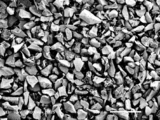
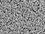
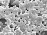
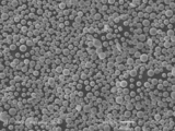
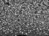
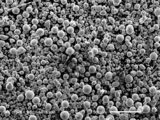
- FIG. 1 It is a scanning electron microscope (SEM) image of the first Ir powder raw material in Example 1, and is a low-magnification SEM image. It is a scanning electron microscope (SEM) image of the first Ir powder raw material in Example 1, and is a high-magnification SEM image.
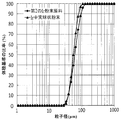
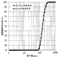
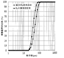
- 3 is a graph showing the integrated particle size distribution of the first Ir powder raw material and the integrated particle size distribution of the Ir hollow spherical powder in Example 1.
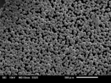
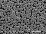
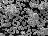
- 6 is an SEM image of Ir hollow spherical powder in Example 1.
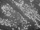
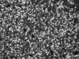
- 6 is an optical microscope image of a cross section of Ir hollow spherical powder in Example 1. It is an optical microscope image of the second Ir powder raw material cross section after the classification in Example 1.
- FIG. 1 It is a graph which shows the integrated particle size distribution of the 2nd Ir powder raw material after classification in Example 1 and the integrated particle size distribution of Ir solid spherical powder.
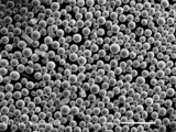
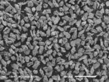
- 6 is an SEM image of Ir solid spherical powder after classification in Example 1.
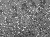
- 6 is an optical microscope image of a cross section of Ir solid spherical powder after classification in Example 1. It is an SEM image of the first Ru powder raw material in Example 2, and is a low-magnification SEM image. It is an SEM image of the first Ru powder raw material in Example 2, and is a high-magnification SEM image.
- 6 is an SEM image of the Ru hollow spherical powder in Example 2.
- 6 is an optical microscope image of a cross section of Ru hollow spherical powder in Example 2. It is an optical microscope image of the second Ru powder raw material cross section after the classification in Example 2.
- FIG. It is a graph which shows the integrated particle size distribution of the 2nd Ru powder raw material after classification in Example 2 and the integrated particle size distribution of a Ru solid spherical powder.
- 6 is an SEM image of the Ru solid spherical powder after the classification in Example 2.
- 6 is an optical microscope image of a cross section of a Ru solid spherical powder after classification in Example 2.
- 6 is an SEM image of Ir solid spherical powder in Comparative Example 1.
- a first powder raw material containing aggregated particles and / or solidified particles having a particle diameter of 1 ⁇ m to 1000 ⁇ m is prepared, and the first powder raw material is introduced into a plasma flame.
- step A of producing a hollow spherical powder having a surface shell having a thickness of 1 ⁇ m to 50 ⁇ m the hollow spherical powder is crushed, and the hollow shape of the hollow spherical powder is crushed to obtain a solid second powder raw material. It has a step B for obtaining a solid spherical powder and a step C for introducing a second powder raw material into a plasma flame, melting the powder, and solidifying the powder.
- the agglomerated particles are particles formed by agglomeration of fine particles with each other, and the consolidated particles are particles formed by agglomeration of fine particles with each other.
- agglomeration means assembling by mutual attraction. Consolidation means being firmly connected.
- the fine particles refer to the primary particles themselves or particles formed by aggregating or solidifying the primary particles with each other.
- the particle size of the fine particles is, for example, 1 nm to 100 nm from the viewpoint of the particle size of the primary particles when industrially producing the powder.
- the agglomerated particles and the solidified particles are preferably porous bodies having a high pore ratio, so that the particle size of the primary particles is 1 nm. It is preferably to 100 nm, and the particle size of the fine particles is preferably 20 nm to 1000 nm.
- the form of the first powder raw material containing agglomerated particles and / or the agglomerated particles includes the form of the first powder raw material containing agglomerated particles and not containing the agglomerated particles, including the agglomerated particles, and not containing the agglomerated particles. There is a form of the first powder raw material, or a form of the first powder raw material containing both agglomerated particles and solidified particles.
- the particle size of the agglomerated particles and / or the consolidated particles contained in the first powder raw material is 1 ⁇ m to 1000 ⁇ m. It is preferably 10 ⁇ m to 500 ⁇ m, and more preferably 50 ⁇ m to 300 ⁇ m. If the particle size is less than 1 ⁇ m, the particle size of the hollow spherical powder obtained in step A is too small, and pulverization is difficult. If the particle size exceeds 1000 ⁇ m, a larger plasma flame is required when producing the hollow spherical powder in step A, and the production efficiency deteriorates.
- the particle size of the agglomerated particles and / or the consolidated particles can be measured by, for example, a particle size distribution measuring device.
- the fine particles In the agglomerated particles, the fine particles have gaps and aggregate, and in the consolidated particles, the fine particles have gaps and solidify. Therefore, there are pores between the fine particles inside the aggregated particles and / or inside the consolidated particles. Further, when the fine particles are secondary particles formed by agglomeration and / or solidification of primary particles, the primary particles are secondary particles by aggregating and / or solidifying with a gap between the primary particles. Inside the fine particles, there are holes inside the fine particles. The pores between these fine particles and the pores inside the fine particles form pores inside the aggregated particles and / or inside the consolidated particles. The pores can be confirmed, for example, by analyzing the SEM image.
- the first powder raw material is made of a metal or alloy having a melting point of 1900 ° C. or higher.
- the upper limit of the melting point is 3500 ° C.
- a metal or alloy having a melting point of 1900 ° C. or higher which was difficult in the conventional spherical powder production method in which the molten metal or droplets come into contact with the jig, can be selected as the first powder raw material.
- the metal or alloy having a melting point of 1900 ° C. or higher is any one of Ir, Ru, Ir-based alloy and Ru-based alloy. Since Ir, Ru, Ir-based alloys and Ru-based alloys have high hardness, solid spherical powder having a high melting point and high hardness can be produced.
- Ir-based alloy examples include Ir-Sc, Ir-Ti, Ir-Mn, Ir-Fe, Ir-Zr, Ir-Mo, Ir-Ru, Ir-Rh, Ir-Hf, Ir-W, Examples thereof include Ir-Re, Ir-Pt and Ir-Re-Zr.
- Ru-based alloy examples include Ru-Cr, Ru-Mn, Ru-Fe, Ru-Co, Ru-Nb, Ru-Ir, Ru-Pt, Ru-Cr-Co, Ru-Cr-Mn and the like. Examples include Ru-Mn-Co.
- M-based alloy (M indicates a metal element such as Ir or Ru) refers to an alloy in which M has the highest content (mass%) among the elements constituting the alloy. It refers to an alloy having an M content of 50% by mass or more.
- the first powder raw material contains at least one of electrolytic powder, reduced powder, mechanical alloy powder and coating powder.
- a hollow spherical powder having a surface shell having a thickness of 1 ⁇ m to 50 ⁇ m has a particle size and a porosity that are easy to produce. Therefore, in step B, a hollow spherical powder that is easy to pulverize can be easily produced.
- electrolytic powder, reduced powder, mechanical alloy powder and coating powder are defined in JIS Z 2500: 2000 "Powder and (metallurgical) terminology”.
- the electrolytic powder is preferably obtained by precipitating the powder on the cathode using an electrolytic method, and washing, dehydrating, and drying the powder.
- the reduced powder is preferably obtained by washing, dehydrating, and drying the produced powder by using an oxide reduction method or a chloride reduction method.
- the mechanical alloy powder is preferably obtained by alloying a plurality of types of solid substances while pulverizing them using a mechanical alloying method.
- the particles of the coating powder have an inside and a surface layer covering the inside.
- the particle form inside include a form in which the inside is aggregated particles and / or a consolidated particle, and a form in which the inside is fine particles.
- the aggregated particles and / or consolidated particles are provided with a surface layer covering the aggregated particles themselves and / or the consolidated particles themselves, and further aggregation is also consolidated. It behaves as one particle without any trouble.
- the fine particles have a surface layer covering the fine particles themselves, and aggregate and / or solidify with other fine particles having a surface layer similar to the fine particles, and the aggregated particles and / or Form solidified particles.
- the interior is made of, for example, a metal or alloy
- the surface layer is made of, for example, a metal, alloy, ceramics or organic matter.
- the compositional forms of the inner and surface layers are: inner made of metal-surface layer made of metal, inner made of metal-surface layer made of alloy, inner made of metal-surface layer made of ceramics, inner made of metal-organic substance.
- the composition of the metal or alloy is different between the inside and the surface layer.
- the coating powder is formed by covering the surface of exposed agglomerated particles and / or solidified particles, or fine particles, with a metal, alloy, ceramics or organic matter, preferably using a method of coating by spray coating, plating, sputtering or concentration. can get.
- the first powder raw material When the first powder raw material is introduced into the plasma flame, preferably, the spherical shape by the high-frequency plasma described in Patent Document 2 except that the supply direction of the first powder raw material is the same as the flow direction of the plasma flame.
- a method similar to the method for producing chemical particles is adopted.
- the first powder raw material is supplied in the direction of the flow of the plasma flame in the high frequency plasma reactor in a countercurrent direction, but in this similar method, the first powder raw material is supplied.
- the supply direction is reversed.
- the particles of the first powder raw material are preferably melted in a plasma flame and transformed into spherical droplets containing gas in the pores.
- the spherical droplets are preferably solidified outside the plasma flame and transformed into hollow spherical powder particles having a low porosity surface shell of 1 ⁇ m to 50 ⁇ m.
- the plasma gas is preferably Ar as a main component, and H 2 , N 2 and / or O 2 is added depending on the situation.
- the plasma flame is preferably generated by passing a high frequency current through the high frequency coil of the plasma generator.
- the thickness of the surface shell of the hollow spherical powder can be controlled by adjusting the components of the plasma gas.
- the porosity of the particles of the first powder raw material refers to the volume ratio of the pores in the entire particles of the first powder raw material. Porosity can be confirmed, for example, by analyzing SEM images.
- the hollow spherical powder is a powder containing particles (hereinafter referred to as hollow spherical particles) in which a surface shell covers the outside, a space is provided inside, and the entire surface of the surface shell forms a convex curved surface outward. Point to.
- the shape of the particles of the hollow spherical powder is, for example, a sphere or an ellipsoid.
- Hollow spherical particles have no cracks, corners or dents in the surface shell.
- the hollow spherical powder may contain particles having cracks in the surface shell, particles having horns in the surface shell, and particles having dents in the surface shell.
- the first powder material having horns did not change into spherical droplets, and the shape of the first powder material was maintained. It is a particle.
- the surface of all the particles of the hollow spherical powder in the field of view of the SEM forms a curved surface convex outward.
- the ratio of particles (hereinafter, also referred to as spherical particles) having no corners or dents and having a "roundness" shown in Equation 1 in the range of 0.5 to 1 is 50% or more.
- the surface shell covers the outside of all the particles of the hollow spherical powder in the field of view of the optical microscope.
- the ratio of particles having a space inside (hereinafter, also referred to as hollow particles) is preferably 50% or more. In both ratios, it is more preferably 70% and even more preferably 90%. If the ratio of spherical particles and / or the ratio of hollow particles is less than 50%, the pulverization treatment may become difficult in step B.
- the thickness of the surface shell of the hollow spherical powder is 1 ⁇ m to 50 ⁇ m. It is more preferably 1 ⁇ m to 30 ⁇ m, and even more preferably 5 ⁇ m to 20 ⁇ m. If the thickness is less than 1 ⁇ m, the volume of the second powder raw material obtained in step B becomes small. As a result, in step C, solid spherical powder having a particle size smaller than the desired particle size is generated and / or particles of the solid spherical powder are agglomerated with each other. If the thickness exceeds 50 ⁇ m, the strength of the surface shell increases, making it difficult to pulverize the hollow spherical powder. In addition, the volume of the second powder raw material obtained in step B increases.
- a large amount of hollow spherical particles may remain in the solid spherical powder after the C step, or a solid spherical powder having a particle diameter larger than the desired particle diameter may be produced.
- the thickness of the surface shell can be measured, for example, by observing the particle cross section of the powder with an optical microscope. In addition, the thickness of the surface layer shell can be confirmed even for particles in which the surface layer shell is cracked. Even particles with cracked surface shells can be supplied to the next step B.
- the particle size distribution of the hollow spherical powder is preferably D10 ⁇ 10 ⁇ m and D90 ⁇ 1000 ⁇ m on a volume basis, more preferably D10 ⁇ 30 ⁇ m and D90 ⁇ 600 ⁇ m, and further preferably D10 ⁇ 50 ⁇ m and D90 ⁇ 200 ⁇ m. ..
- the particle size of the hollow spherical powder depends on the particle size of the first powder raw material.
- the particle size distribution of the hollow spherical powder can be measured by, for example, a particle size distribution measuring device.
- Step B the hollow shape of the hollow spherical powder is crushed. Since the hollow spherical powder is formed through melting and solidification, it is considered that the porosity of the surface shell is low and the relative density is high. Since the second powder raw material is a powder raw material obtained by crushing the surface layer shell, the relative density of the surface layer shell can be maintained.
- the pulverization treatment of the hollow spherical powder is preferably impact pulverization. Since impact pulverization can efficiently pulverize even particles on the order of microns, it is possible to obtain a second powder raw material in which the hollow spherical powder is made fine and the particle size is adjusted.
- the material of the jig used for impact crushing is preferably a material that is not mixed due to scraping of the jig, and is, for example, agate and zirconia.
- the particle size distribution of the second powder raw material is preferably D10 ⁇ 10 ⁇ m and D90 ⁇ 900 ⁇ m on a volume basis, more preferably D10 ⁇ 25 ⁇ m and D90 ⁇ 500 ⁇ m, and further preferably D10 ⁇ 40 ⁇ m and D90 ⁇ 180 ⁇ m. Is.
- the particle size distribution of the second powder raw material depends on the form of the pulverization treatment. By adjusting the particle size of the second powder raw material, a solid spherical powder having a desired particle size can be produced.
- the particle size distribution of the second powder raw material can be measured by, for example, a particle size distribution measuring device.
- step C a method similar to the method for producing spheroidized particles by high-frequency plasma described in Patent Document 2 is preferably used except that the supply direction of the second powder raw material is the same as the flow direction of the plasma flame.
- the particles of the second powder raw material are preferably melted in a plasma flame and transformed into spherical droplets.
- Spherical droplets preferably solidify outside the plasma flame and transform into solid spherical powder particles.
- the plasma gas is preferably Ar as a main component, and H 2 , N 2 and / or O 2 is added depending on the situation.
- the plasma flame is preferably generated by passing a high frequency current through the high frequency coil of the plasma generator. In this improved method, when the second powder raw material having a low porosity is melted, gas does not enter the spherical droplets, so that a solid spherical powder can be produced.
- the solid spherical powder refers to a powder containing particles (hereinafter, referred to as solid spherical particles) having no space inside and having a curved surface whose entire surface is convex outward.
- the shape of the solid spherical powder is, for example, a sphere or an ellipsoid.
- Solid spherical particles have no chips, corners or dents.
- the solid spherical powder may contain particles having chips on the surface, particles having corners on the surface, and particles having dents on the surface.
- the second powder material having horns did not change into spherical droplets, and the shape of the second powder material was maintained. It is a particle.
- the ratio of the spherical particles to the total particles of the solid spherical powder in the field of view of the SEM is 80%.
- the particles having no space inside among all the particles of the solid spherical powder in the field of view of the optical microscope (
- the ratio is preferably 80% or more. In both ratios, it is more preferably 90% or more, still more preferably 95% or more. If the ratio of spherical particles is less than 80%, the fluidity of the powder is lowered, and there is a possibility that the superiority derived from the spherical shape cannot be shown.
- the ratio of solid particles is less than 80%, it may not be possible to use it as a raw material for a modeled product having a high relative density.
- the whole particles of the solid spherical powder can be evaluated by SEM images, image analysis software, and optical microscope images.
- the particle size of the solid spherical powder depends on the particle size of the second powder raw material.
- the particle size distribution of the solid spherical powder can be measured by, for example, a particle size distribution measuring device.
- ⁇ Process D and process E> In the method for producing a solid spherical powder according to the present embodiment, it is preferable to further include a D step for classifying the second powder raw material and / or an E step for classifying the solid spherical powder.
- the form of the manufacturing method further having the D step and / or the E step is the form of the manufacturing method having the A step, the B step, the D step and the C step, and the form of the manufacturing method having the A step, the B step, the C step and the E step. It is a form of a manufacturing method having a step A, a step B, a step D, a step C, and a step E.
- the particle size distribution constituting the second powder raw material can be narrowed, it becomes easier to obtain a solid spherical powder having a desired particle size, and the fluidity of the solid spherical powder can be further increased.
- the suitable particle size of the solid spherical powder varies depending on the application, and is generally 45 to 105 ⁇ m for EBM applications and 10 to 45 ⁇ m for SLM applications. For applications, it is 45 to 105 ⁇ m, and for medical applications, it is 200 to 300 ⁇ m. In the present embodiment, even if the range of the suitable particle size of the solid spherical powder has a width wider than the width of the general range in each of these applications, the solid spherical powder can be used for each application. it can.
- the apparent density of the solid spherical powder specified in JIS Z 2504: 2012 "Metal powder-apparent density measuring method" is 50% or more of the true density. Is preferable.
- the reasons for the low apparent density are the low fluidity due to the low roundness shown in Equation 1 and the presence of pores inside the particles. The low fluidity causes the powder supply to become unstable in the addition manufacturing process, and the presence of the pores in the particles causes the pores to remain inside the modeled product. For these reasons, if the apparent density is less than 50% of the true density, it may not be possible to use it as a raw material for a modeled product having a high relative density.
- the impurity mixing ratio in the solid spherical powder produced by the method for producing the solid spherical powder according to the present embodiment is preferably 1% by mass or less. It is more preferably 0.1% by mass or less, and further preferably 0.05% by mass or less.
- the impurity mixing rate becomes high, the optimum range (process window) of the manufacturing conditions changes, so that it becomes difficult to control the production of a high-quality modeled product.
- impurities may contribute to the generation of internal defects and cracks, and may not be used as a raw material for molded products having a high relative density.
- the impurity refers to a substance mixed in the steps A to E, such as a fragment of a jig used for the crushing process.
- the lower limit of the impurity mixing rate is 0.0001% by mass from the viewpoint of measurement accuracy.
- the impurity mixing rate can be measured, for example, by comparing the elemental analysis of the first powder raw material with the elemental analysis of the solid spherical powder.
- the oxygen content in the solid spherical powder produced by the method for producing the solid spherical powder according to the present embodiment is preferably 0.1% by mass or less. If the oxygen content exceeds 0.1% by mass, oxidation may occur and it may not be possible to use it as a raw material for high-quality modeled products.
- the oxygen content can be measured, for example, by gas analysis of the solid spherical powder.
- the method for manufacturing a modeled product of the present embodiment is an additional manufacturing method including a step of laminating layers obtained by at least partially melting and solidifying the irradiated powder by high-energy irradiation to form a modeled product.
- the powder is a solid spherical powder produced by the method for producing a solid spherical powder according to the present embodiment.
- a solid spherical powder made of a metal or alloy having a high melting point and difficult to process is selected as the irradiated powder. Can be done.
- Examples of the form of the addition manufacturing method include known forms of the addition manufacturing method such as EBM, SLM and LMD.
- EBM electronic bookmaker
- SLM surface-to-process metal
- LMD liquid crystal display
- the relative density of the modeled product is preferably 99% or more. If it is less than 99%, it may not meet the quality required for the modeled product.
- Preferred specific examples of the modeled product include a modeled product having a complicated shape such as an electrode, a processing tool, and a crucible for the ⁇ -PD method.
- the relative density can be measured by, for example, the in-liquid weighing method described in JIS Z 8807: 2012 “Method for measuring solid density and specific gravity”.
- ⁇ Particle size distribution of the first powder raw material The particle size distribution of the first powder raw material was measured by laser diffraction using a particle size distribution measuring device (laser micron sizer LMS-30, manufactured by Seishin Enterprise Co., Ltd.). The particle size (D10) corresponding to 10% and the particle size (D90) corresponding to 90% of the integrated particle size distribution measured on a volume basis are read, and the section between these points is an index of the particle size of the first powder raw material. And said.
- ⁇ Porosity of particles of the first powder raw material The particles of the first powder raw material were observed by SEM, and the observed SEM image was analyzed by image analysis software (Quick Grain, manufactured by Innotek) to confirm the porosity of the particles. Specifically, the contrast of the SEM image was emphasized, black and white were binarized, and the ratio of the region where no powder was present to the entire region was derived and used as the porosity.
- Elemental analysis was performed using a glow discharge mass spectrometer (ELEMENT GD, manufactured by Thermo Fisher Scientific) using a glow discharge mass spectrometry (GDMS).
- ELEMENT GD manufactured by Thermo Fisher Scientific
- GDMS glow discharge mass spectrometry
- the number of hollow particles among them was counted, and the ratio of hollow particles to all the hollow spherical powder particles was determined.
- the thickness of the surface shell of all the hollow spherical particles existing in the field of view was measured, and the average value was calculated to obtain the thickness of the surface shell of the hollow spherical powder.
- ⁇ Particle size distribution of hollow spherical powder The particle size distribution of the hollow spherical powder was measured using a particle size distribution measuring device. The particle size (D10) corresponding to 10% and the particle size (D90) corresponding to 90% of the integrated particle size distribution measured on a volume basis were read, and the sections of these points were used as indexes of the particle size of the hollow spherical powder.
- ⁇ Particle size distribution of the second powder raw material The particle size distribution of the second powder raw material was measured using a particle size distribution measuring device. D10 and D90 of the integrated particle size distribution measured on a volume basis were read, and the section between these points was used as an index of the particle size of the second powder raw material.
- ⁇ Particle size distribution of solid spherical powder The particle size distribution of the solid spherical powder was measured using a particle size distribution measuring device. D10 and D90 of the integrated particle size distribution measured on a volume basis were read, and the section between these points was used as an index of the particle size of the solid spherical powder.
- the yield was defined as ⁇ (mass of solid spherical powder having a desired particle size) / (mass of input raw material) ⁇ ⁇ 100 (unit%).
- the raw material to be supplied is a first raw material powder, a wire or a round bar.
- the particle size distribution measurement is volume-based, in this example and comparative example, the solid spherical powder was considered to be sufficiently dense (solid), and the volume-based yield and the mass-based yield were set to be the same.
- Example 1 A first Ir powder raw material (purified powder, made of fluya metal) containing aggregated particles and / or consolidated particles of an Ir porous body having a particle diameter of 1 ⁇ m to 1000 ⁇ m was prepared. The SEM image of the first Ir powder raw material was confirmed.
- FIG. 1 (a) shows a low-magnification SEM image in a field of view of 2000 ⁇ 2500 ⁇ m
- FIG. 1 (b) shows a high-magnification SEM image in a field of view of 9 ⁇ 12 ⁇ m. From FIG. 1 (a), it was confirmed that the particle size of the first Ir powder raw material was 1 ⁇ m or more and 1000 ⁇ m or less, and from FIG.
- pores were confirmed in the particles of the first Ir powder raw material. ..
- the porosity of the particles of the first Ir powder raw material was calculated by analyzing the SEM image of FIG. 1 (b). The porosity was 43.39%.
- the particle size distribution of the first Ir powder raw material was measured using a particle size distribution measuring device.
- FIG. 2 shows a graph of the integrated particle size distribution. As a result of the measurement, the particle size distribution of the first Ir powder raw material was D10 of 50.0 ⁇ m and D90 of 244.7 ⁇ m. Elemental analysis of the first Ir powder raw material was performed using a glow discharge mass spectrometer. The total content of impurities was 0.0064% by mass.
- FIG. 3 shows an SEM image of Ir hollow spherical powder.
- FIG. 4 shows an optical microscope image of a cross section of Ir hollow spherical powder.
- FIG. 2 shows a graph of the integrated particle size distribution of the Ir hollow spherical powder.
- the ratio of spherical particles to all the particles of the obtained Ir hollow spherical powder was 95% or more.
- the ratio of hollow particles to all the particles of the obtained Ir hollow spherical powder was 75% or more.
- the thickness range of the surface shell was 5 ⁇ m to 25 ⁇ m, and the average thickness of the surface shell was 15 ⁇ m.
- the particle size distribution D10 was 34.3 ⁇ m and D90 was 210.0 ⁇ m.
- the content of Si contained in the Ir hollow spherical powder was measured by GDMS using a glow discharge mass spectrometer. As a result of the measurement, the content of Si as an impurity was 0.0003% by mass.
- Step B and Step D> When the volume of the container is 100, Ir hollow spherical powder is put into a planetary mill container made of Menou so that the volume is 10 or less, and 100 Menou balls having a ball diameter of 10 mm are put into the planetary rotary ball mill. (LP-4, manufactured by Ito Seisakusho) was pulverized for 1 hr under the condition of 200 rpm, and the hollow shape of the hollow spherical powder was pulverized to obtain a second Ir powder raw material.
- LP-4 manufactured by Ito Seisakusho
- FIG. 5 shows an optical microscope image of a cross section of the second Ir powder raw material after classification.
- FIG. 6 shows a graph of the integrated particle size distribution of the second Ir powder raw material after classification.
- the particle size distribution D10 was 38.1 ⁇ m and D90 was 94.7 ⁇ m.
- the content of Si contained in the second Ir powder raw material was measured by GDMS using a glow discharge mass spectrometer. As a result of the measurement, it was confirmed that the content of Si as an impurity was 0.0026% by mass, and the increase in the content of Si contained in the second Ir powder raw material due to agate balls was suppressed to a slight increase. ..
- FIG. 7 shows an SEM image of the Ir solid spherical powder after classification
- FIG. 8 shows an optical microscope image of a cross section of the Ir solid spherical powder after classification.
- FIG. 6 shows a graph of the integrated particle size distribution of the Ir solid spherical powder after classification.
- the ratio of spherical particles to all the particles of the obtained Ir solid spherical powder was 99% or more.
- the ratio of solid particles was 94% or more.
- the particle size distribution D10 was 38.2 ⁇ m and D90 was 79.2 ⁇ m.
- the apparent density was 13.16 g / cm 3 , which was 58.3% of the true density.
- GDMS glow discharge mass spectrometer
- the content of impurities was 0.0331% by mass. Therefore, the impurity mixing rate was 0.0267% by mass from ⁇ (impurity content in the Ir solid spherical powder)-(impurity content in the first Ir powder raw material) ⁇ . Further, from a gas analyzer (TS600, manufactured by LECO), the oxygen content was less than 0.0014% by mass, which is the lower limit of quantification.
- the Ir solid spherical powder of Example 1 obtained by classification can be used for SLM, and as a result of mass measurement, a yield of 79.5% was shown.
- the ratio of the solid spherical powder having a particle size of 10 ⁇ m to 45 ⁇ m in the Ir solid spherical powder obtained by classification is about 28% on a volume basis, which is suitable for SLM.
- the yield of the solid spherical powder having a particle diameter of 10 ⁇ m to 45 ⁇ m was 79.5 ⁇ 0.28 ⁇ 22% on a volume basis.
- a cylindrical shaped product having a size of ⁇ 3.8 ⁇ 19 mm was produced by an SLM device (SLM280HL, manufactured by SLM). Then, the outer surface was prepared by grinding to obtain a molded product having a diameter of 3.6 ⁇ 18.6 mm, and the relative density of the shaped product was measured by the submerged weighing method using the specific gravity measurement kit for XP / XS balance. The relative density of this modeled product was 99.5%.
- Example 2 ⁇ Process A> In Example 2, the operation was carried out in the same manner as in Example 1 except that the modeled product was not produced.
- a first Ru powder raw material (purified powder, made of fluya metal) containing aggregated particles and / or consolidated particles of a Ru porous body having a particle diameter of 1 ⁇ m to 1000 ⁇ m was prepared. The SEM image of the first Ru powder raw material was confirmed.
- FIG. 9 (a) shows a low-magnification SEM image in a field of view of 2000 ⁇ 2500 ⁇ m
- FIG. 9 (b) shows a high-magnification SEM image in a field of view of 9 ⁇ 12 ⁇ m. From the SEM image of FIG.
- the particle size of the first Ru powder raw material was 1 ⁇ m or more and 1000 ⁇ m or less, and from the SEM image of FIG. 9 (b), the particles of the first Ru powder raw material. Pore was confirmed inside.
- the porosity of the particles of the first Ru powder raw material was calculated in the same manner as in Example 1. The porosity was 20.27%.
- the particle size distribution of the first Ru powder raw material was measured using a particle size distribution measuring device.
- FIG. 10 shows a graph of the integrated particle size distribution. As a result of the measurement, the particle size distribution of the first Ru powder raw material was 106.5 ⁇ m for D10 and 252.1 ⁇ m for D90.
- the elemental analysis of the first Ru powder raw material was carried out in the same manner as in Example 1. The total content of impurities was 0.0138% by mass.
- the first Ir powder raw material is changed to the first Ru powder raw material, the supply amount of the first Ru powder raw material is set to 8 g / min, the carrier gas flow rate is set to 10 L / min, and the high frequency plasma gas is Ar. to the mixed gas obtained by adding H 2, except that the plasma power to 29.0KW, to prepare a Ru hollow spherical powder in the same manner as in example 1.
- FIG. 11 shows an SEM image of the Ru hollow spherical powder.
- FIG. 12 shows an optical microscope image of a cross section of Ru hollow spherical powder.
- FIG. 10 shows a graph of the integrated particle size distribution of the Ru hollow spherical powder.
- the ratio of spherical particles to all the particles of the obtained Ru hollow spherical powder was 99% or more.
- the ratio of hollow particles to all the particles of the obtained Ru hollow spherical powder was 85% or more.
- the thickness range of the surface shell was 10 ⁇ m to 30 ⁇ m, and the average thickness of the surface shell was 20 ⁇ m.
- the particle size distribution D10 was 99.0 ⁇ m and D90 was 230.0 ⁇ m.
- the content of Si contained in the Ru hollow spherical powder was measured. As a result of the measurement, the content of Si as an impurity was 0.0013% by mass.
- Step B and Step D> A second Ru powder raw material was obtained in the same manner as in Example 1 except that the second Ir hollow spherical powder was changed to the second Ru hollow spherical powder. Then, using a metal sieve having an opening of 22 ⁇ m and a metal sieve having an opening of 63 ⁇ m, the second Ru powder raw material was classified so that the preferable range of the particle size was more than 22 ⁇ m and 63 ⁇ m or less.
- FIG. 13 shows an optical microscope image of the second Ru powder raw material after the classification.
- FIG. 14 shows a graph of the integrated particle size distribution of the crushed powder of the second Ru powder raw material after classification. As a result of the measurement, D10 was 31.0 ⁇ m and D90 was 84.8 ⁇ m.
- Example 2 In the same manner as in Example 1, the content of Si contained in the second Ru powder raw material was measured. As a result of the measurement, it was confirmed that the content of Si as an impurity was 0.0620% by mass, and the increase in the content of Si contained in the second Ru powder raw material due to agate balls was suppressed to a slight increase. ..
- FIG. 16 shows an optical microscope image of a cross section of the Ru solid spherical powder after classification. Further, FIG. 14 shows a graph of the integrated particle size distribution of the Ru solid spherical powder after the classification.
- the ratio of spherical particles to all the particles of the obtained Ru solid spherical powder was at least 95% or more.
- the particle size distribution D10 was 26.2 ⁇ m and D90 was 60.4 ⁇ m.
- the apparent density was 7.30 g / cm 3 , which was 58.6% of the true density.
- the content of impurities was 0.0152% by mass. Therefore, when calculated in the same manner as in Example 1, the impurity mixing ratio was 0.0014% by mass. Moreover, the oxygen content was 0.0065% by mass from the gas analyzer. In the same manner as in Example 1, the yield of the Ru solid spherical powder obtained by classification was derived and showed 86.9%.
- the ratio of the Ru solid spherical powder having a particle diameter of 10 ⁇ m to 45 ⁇ m in the Ru solid spherical powder obtained by classification was about 67% on a volume basis, so that the particles were suitable for SLM.
- the yield of the Ru solid spherical powder having a diameter of 10 ⁇ m to 45 ⁇ m was 86.9 ⁇ 0.67 ⁇ 58% on a volume basis.
- FIG. 17 shows an SEM image of Ir solid spherical powder. Further, FIG. 18 shows a graph of the integrated particle size distribution.
- the spherical powder was confirmed, and some aggregates of powder particles were confirmed.
- D10 of the particle size distribution was 47.6 ⁇ m and D90 was 237.6 ⁇ m, and the powder had a wide particle size distribution.
- the ratio of Ir solid spherical powder having a particle size of 10 ⁇ m to 45 ⁇ m was about 9% on a volume basis. Therefore, the yield of Ir solid spherical powder having a particle size of 10 ⁇ m to 45 ⁇ m suitable for SLM was 91 ⁇ 0.09 ⁇ 8% on a volume basis. Due to the poor yield, this method for producing Ir solid spherical powder was not suitable as a material for SLM.
- a Pt-10Rh round bar having a diameter of 16.0 to 16.5 and a length of 550 mm was prepared.
- a Pt-10Rh solid spherical powder was prepared using this Pt-10Rh round bar. Specifically, a round bar was supplied to an electrode-induced dissolved gas atomizing apparatus without producing a hollow spherical powder and pulverizing the powder to produce a Pt-10Rh solid spherical powder. From the mass measurement, 99.1% of the charged Pt-10Rh round bar became Pt-10Rh solid spherical powder, 0.6% was fixed to the apparatus, and 0.3% was volatilized and disappeared.
- FIG. 19 (a) shows a low-magnification SEM image of the Pt-10Rh solid spherical powder under the sieve
- FIG. 19 (b) shows a high-magnification SEM image
- FIG. 20 shows an image of the appearance of the Pt-10Rh powder on the sieve
- FIG. 21 shows a graph of the integrated particle size distribution of the Pt-10Rh solid spherical powder under the sieve.
- the ratio of the Pt-10Rh powder on the sieve was 70%, and the ratio of the Pt-10Rh solid spherical powder under the sieve was 30%.
- the Pt-10Rh powder on the sieve was a powder in which most of the constituent particles were in the form of flakes.
- the Pt-10Rh solid spherical powder under the sieve was a powder in which most of the constituent particles were spherical or substantially spherical.
- the particle size distribution D10 was 36.7 ⁇ m and D90 was 214.1 ⁇ m.
- the ratio of the Pt-10Rh solid spherical powder having a particle size of 10 ⁇ m to 45 ⁇ m was about 18% on a volume basis. Therefore, the yield of Pt-10Rh solid spherical powder having a particle diameter of 10 ⁇ m to 45 ⁇ m suitable for SLM is 99.1 ⁇ 0.3 ⁇ 0.18 ⁇ 5% on a volume basis, which is a small amount with respect to the total amount of treatment. I could only get it. This Pt-10Rh solid spherical powder was not suitable as a material for SLM.
- the obtained solid spherical powder has a wide particle size distribution and agglomeration occurs, so that Comparative Example 1 was not suitable for producing a material for addition production.
- Comparative Example 2 it was difficult because it took time to prepare the round bar.
- the solid spherical powder obtained in Comparative Example 2 has a melting point lower than that of the solid spherical powder of Example, but has a wide particle size distribution, most of which are flaked, and the yield is poor. Comparative Example 2 was unsuitable for producing a material for addition production.
Landscapes
- Engineering & Computer Science (AREA)
- Chemical & Material Sciences (AREA)
- Materials Engineering (AREA)
- Manufacturing & Machinery (AREA)
- Physics & Mathematics (AREA)
- Mechanical Engineering (AREA)
- Optics & Photonics (AREA)
- Nanotechnology (AREA)
- Thermal Sciences (AREA)
- Plasma & Fusion (AREA)
- Metallurgy (AREA)
- Organic Chemistry (AREA)
- Powder Metallurgy (AREA)
- Manufacture Of Metal Powder And Suspensions Thereof (AREA)
Abstract
L'objectif de la présente invention est de fournir un procédé de production d'une poudre sphérique solide à fluidité élevée qui a un rendement élevé et qui facilite le moulage avec une taille de grain souhaitée en utilisant un matériau à point de fusion élevé et difficile à mettre en œuvre comme matière première, ainsi qu'un procédé de production d'un produit façonné présentant une densité relative élevée en utilisant la poudre sphérique solide comme matériau de production supplémentaire. Le procédé de production d'une poudre sphérique solide selon la présente invention comprend : une étape A consistant à préparer une première matière première pulvérulente contenant des particules agglomérées et/ou des particules consolidées ayant un diamètre de particule de 1 à 1000 µm, à introduire la première matière première pulvérulente dans une flamme plasma et à préparer une poudre sphérique creuse dont les particules ont une enveloppe extérieure de 1 à 50 µm d'épaisseur ; une étape B consistant à soumettre la poudre sphérique creuse à une opération de broyage pour écraser la forme creuse de la poudre sphérique creuse et obtenir une seconde matière première pulvérulente qui est solide ; et une étape C consistant à introduire la seconde matière première pulvérulente dans une flamme de plasma, et faire fondre et solidifier cette dernière pour obtenir une poudre sphérique solide.
Priority Applications (1)
| Application Number | Priority Date | Filing Date | Title |
|---|---|---|---|
| US17/442,512 US20220176447A1 (en) | 2019-03-27 | 2020-03-25 | Method of producing solid spherical powder,and method of producing shaped product |
Applications Claiming Priority (2)
| Application Number | Priority Date | Filing Date | Title |
|---|---|---|---|
| JP2019-061338 | 2019-03-27 | ||
| JP2019061338A JP7296232B2 (ja) | 2019-03-27 | 2019-03-27 | 中実球状粉末の製造方法及び造形製品の製造方法 |
Publications (1)
| Publication Number | Publication Date |
|---|---|
| WO2020196578A1 true WO2020196578A1 (fr) | 2020-10-01 |
Family
ID=72610727
Family Applications (1)
| Application Number | Title | Priority Date | Filing Date |
|---|---|---|---|
| PCT/JP2020/013198 Ceased WO2020196578A1 (fr) | 2019-03-27 | 2020-03-25 | Procédé de production d'une poudre sphérique solide et procédé de production d'un produit façonné |
Country Status (3)
| Country | Link |
|---|---|
| US (1) | US20220176447A1 (fr) |
| JP (1) | JP7296232B2 (fr) |
| WO (1) | WO2020196578A1 (fr) |
Families Citing this family (2)
| Publication number | Priority date | Publication date | Assignee | Title |
|---|---|---|---|---|
| JP2025523625A (ja) * | 2022-07-06 | 2025-07-23 | ヴァルス ベジッツ ゲーエムベーハー | 超高性能金属積層造形コンポーネントの製造方法 |
| KR102924528B1 (ko) * | 2022-12-01 | 2026-02-09 | 주식회사 비츠로넥스텍 | 텅스텐 합금 스크랩으로부터 텅스텐 합금 중공 분말의 제조방법 및 텅스텐 합금 중공 분말 |
Citations (5)
| Publication number | Priority date | Publication date | Assignee | Title |
|---|---|---|---|---|
| JPH06240309A (ja) * | 1993-02-12 | 1994-08-30 | Soken Kagaku Kk | 中空金属微粒子、中空金属微粒子含有金属粒子群およびこれらの製造方法 |
| JP2004091843A (ja) * | 2002-08-30 | 2004-03-25 | Hitachi Metals Ltd | 高純度高融点金属粉末の製造方法 |
| JP2014518939A (ja) * | 2011-05-04 | 2014-08-07 | ヒ スング メタル リミテッド | ルテニウム(Ru)ターゲット製造のためのルテニウム粉末製造方法 |
| KR20150031750A (ko) * | 2013-09-16 | 2015-03-25 | 한국생산기술연구원 | Rf 플라즈마 처리를 이용한 루테늄-크롬 합금 분말의 제조방법 |
| JP2018009240A (ja) * | 2016-03-07 | 2018-01-18 | ヘレウス ドイチュラント ゲーエムベーハー ウント カンパニー カーゲー | 貴金属粉末及び部品の製造のためのその使用 |
Family Cites Families (1)
| Publication number | Priority date | Publication date | Assignee | Title |
|---|---|---|---|---|
| CA3118414C (fr) * | 2014-03-11 | 2026-03-17 | Tekna Plasma Systems Inc. | Procede et appareil de production de particules de poudre par atomisation d'une substance de base sous la forme d'un element allonge |
-
2019
- 2019-03-27 JP JP2019061338A patent/JP7296232B2/ja active Active
-
2020
- 2020-03-25 US US17/442,512 patent/US20220176447A1/en not_active Abandoned
- 2020-03-25 WO PCT/JP2020/013198 patent/WO2020196578A1/fr not_active Ceased
Patent Citations (5)
| Publication number | Priority date | Publication date | Assignee | Title |
|---|---|---|---|---|
| JPH06240309A (ja) * | 1993-02-12 | 1994-08-30 | Soken Kagaku Kk | 中空金属微粒子、中空金属微粒子含有金属粒子群およびこれらの製造方法 |
| JP2004091843A (ja) * | 2002-08-30 | 2004-03-25 | Hitachi Metals Ltd | 高純度高融点金属粉末の製造方法 |
| JP2014518939A (ja) * | 2011-05-04 | 2014-08-07 | ヒ スング メタル リミテッド | ルテニウム(Ru)ターゲット製造のためのルテニウム粉末製造方法 |
| KR20150031750A (ko) * | 2013-09-16 | 2015-03-25 | 한국생산기술연구원 | Rf 플라즈마 처리를 이용한 루테늄-크롬 합금 분말의 제조방법 |
| JP2018009240A (ja) * | 2016-03-07 | 2018-01-18 | ヘレウス ドイチュラント ゲーエムベーハー ウント カンパニー カーゲー | 貴金属粉末及び部品の製造のためのその使用 |
Also Published As
| Publication number | Publication date |
|---|---|
| US20220176447A1 (en) | 2022-06-09 |
| JP7296232B2 (ja) | 2023-06-22 |
| JP2020158851A (ja) | 2020-10-01 |
Similar Documents
| Publication | Publication Date | Title |
|---|---|---|
| Sun et al. | Characterization, preparation, and reuse of metallic powders for laser powder bed fusion: a review | |
| Popovich et al. | Metal powder additive manufacturing | |
| TWI877173B (zh) | 球形鉭-鈦合金粉末,包含彼之產品及製備彼之方法 | |
| JP6703759B2 (ja) | TiAl金属間化合物粉末の製造方法およびTiAl金属間化合物粉末 | |
| JP6493561B2 (ja) | ハイエントロピー合金部材、該合金部材の製造方法、および該合金部材を用いた製造物 | |
| EP3787822B1 (fr) | Poudre d'alliage ods, son procédé de fabrication par traitement plasma, et son utilisation | |
| WO2012102162A1 (fr) | Agent d'affinage de grain cristallin pour coulage et son procédé de production | |
| JP2009242181A (ja) | 炭化タングステン粉末、炭化タングステン粉末の製造方法 | |
| EP3950177B1 (fr) | Alliage à base de ni, poudre d'alliage à base de ni, élément d'alliage à base de ni et produit comprenant l'élément d'alliage à base de ni | |
| German et al. | Binder and polymer assisted powder processing | |
| CN1798870B (zh) | 放电表面处理用电极、放电表面处理用电极的制造方法、放电表面处理装置和放电表面处理方法 | |
| JP6955254B2 (ja) | 高濃度に異質核粒子を含有した鋳造用結晶粒微細化剤およびその製造方法 | |
| KR102924528B1 (ko) | 텅스텐 합금 스크랩으로부터 텅스텐 합금 중공 분말의 제조방법 및 텅스텐 합금 중공 분말 | |
| JP7296232B2 (ja) | 中実球状粉末の製造方法及び造形製品の製造方法 | |
| Ciurans-Oset et al. | Fabrication of spherical Ti-V-Zr-Nb-Mo-Hf-Ta-W refractory high-entropy alloy by a combination of spark plasma sintering, cryogenic grinding, and plasma centrifugal atomization | |
| JP2020164916A (ja) | 造形用粉末、この粉末の製造方法及び造形品の製造方法 | |
| CN101495677B (zh) | 覆膜以及覆膜的形成方法 | |
| JP6915700B2 (ja) | 粉末材料、付加製造用粉末材料、および粉末材料の製造方法 | |
| CN119913387A (zh) | 一种钛钽合金构件及其制备方法、应用 | |
| RU2707455C1 (ru) | Сферический порошок псевдосплава на основе вольфрама и способ его получения | |
| JP2021075736A (ja) | Cr基合金付加加工物およびその製造方法、ならびにCr基合金粉末の製造方法 | |
| JP7378907B2 (ja) | 3d造形用混合粉末の製造方法 | |
| JP2023126112A (ja) | Cu合金及び3D造形体 | |
| JP7713432B2 (ja) | アルミニウム基材の製造方法 | |
| JP2023147173A (ja) | Cu合金の製造方法 |
Legal Events
| Date | Code | Title | Description |
|---|---|---|---|
| 121 | Ep: the epo has been informed by wipo that ep was designated in this application |
Ref document number: 20777168 Country of ref document: EP Kind code of ref document: A1 |
|
| NENP | Non-entry into the national phase |
Ref country code: DE |
|
| 122 | Ep: pct application non-entry in european phase |
Ref document number: 20777168 Country of ref document: EP Kind code of ref document: A1 |