WO2020196596A1 - Dispositif d'aide au développement, procédé d'aide au développement et programme informatique - Google Patents
Dispositif d'aide au développement, procédé d'aide au développement et programme informatique Download PDFInfo
- Publication number
- WO2020196596A1 WO2020196596A1 PCT/JP2020/013248 JP2020013248W WO2020196596A1 WO 2020196596 A1 WO2020196596 A1 WO 2020196596A1 JP 2020013248 W JP2020013248 W JP 2020013248W WO 2020196596 A1 WO2020196596 A1 WO 2020196596A1
- Authority
- WO
- WIPO (PCT)
- Prior art keywords
- power storage
- deterioration
- storage device
- simulation
- development support
- Prior art date
- Legal status (The legal status is an assumption and is not a legal conclusion. Google has not performed a legal analysis and makes no representation as to the accuracy of the status listed.)
- Ceased
Links
Images





Classifications
-
- G—PHYSICS
- G06—COMPUTING OR CALCULATING; COUNTING
- G06F—ELECTRIC DIGITAL DATA PROCESSING
- G06F30/00—Computer-aided design [CAD]
- G06F30/20—Design optimisation, verification or simulation
-
- H—ELECTRICITY
- H01—ELECTRIC ELEMENTS
- H01M—PROCESSES OR MEANS, e.g. BATTERIES, FOR THE DIRECT CONVERSION OF CHEMICAL ENERGY INTO ELECTRICAL ENERGY
- H01M10/00—Secondary cells; Manufacture thereof
- H01M10/42—Methods or arrangements for servicing or maintenance of secondary cells or secondary half-cells
-
- H—ELECTRICITY
- H01—ELECTRIC ELEMENTS
- H01M—PROCESSES OR MEANS, e.g. BATTERIES, FOR THE DIRECT CONVERSION OF CHEMICAL ENERGY INTO ELECTRICAL ENERGY
- H01M10/00—Secondary cells; Manufacture thereof
- H01M10/42—Methods or arrangements for servicing or maintenance of secondary cells or secondary half-cells
- H01M10/4285—Testing apparatus
-
- H—ELECTRICITY
- H01—ELECTRIC ELEMENTS
- H01M—PROCESSES OR MEANS, e.g. BATTERIES, FOR THE DIRECT CONVERSION OF CHEMICAL ENERGY INTO ELECTRICAL ENERGY
- H01M10/00—Secondary cells; Manufacture thereof
- H01M10/42—Methods or arrangements for servicing or maintenance of secondary cells or secondary half-cells
- H01M10/48—Accumulators combined with arrangements for measuring, testing or indicating the condition of cells, e.g. the level or density of the electrolyte
-
- G—PHYSICS
- G01—MEASURING; TESTING
- G01R—MEASURING ELECTRIC VARIABLES; MEASURING MAGNETIC VARIABLES
- G01R31/00—Arrangements for testing electric properties; Arrangements for locating electric faults; Arrangements for electrical testing characterised by what is being tested not provided for elsewhere
- G01R31/36—Arrangements for testing, measuring or monitoring the electrical condition of accumulators or electric batteries, e.g. capacity or state of charge [SoC]
- G01R31/392—Determining battery ageing or deterioration, e.g. state of health
-
- G—PHYSICS
- G06—COMPUTING OR CALCULATING; COUNTING
- G06F—ELECTRIC DIGITAL DATA PROCESSING
- G06F2119/00—Details relating to the type or aim of the analysis or the optimisation
- G06F2119/04—Ageing analysis or optimisation against ageing
Definitions
- the present invention relates to a development support device, a development support method, and a computer program mounted on a computer.
- the amount of elements used for battery electrodes is small, and it is thought that reuse will progress in the future. However, reuse may be difficult depending on the deterioration state, and it is important to grasp the deterioration behavior based on the deterioration mechanism in order to grasp the recovery rate and perform appropriate recycling.
- An object of the present invention is to provide a development support device, a development support method, and a computer program capable of providing a deterioration simulation result or a simulation program of a power storage device in consideration of a deterioration mechanism to a user via a network.
- the development support device is a receiving unit that receives selection information regarding the deterioration mechanism of the power storage device from the terminal device after user authentication of the terminal device, and deterioration selected based on the received selection information.
- a simulation execution unit that simulates the deterioration of the power storage device using a mechanism, a simulation result by the simulation execution unit, or a simulation program that is executed when simulating the deterioration of the power storage device is transmitted to the terminal device.
- a transmitter is provided.
- the development support method presents a plurality of options regarding the deterioration mechanism of the power storage device by using the development support device communicably connected to the terminal device, and presents selection information regarding the selected deterioration mechanism. Is received from the terminal device, and based on the received selection information, the deterioration of the power storage device is simulated using the selected deterioration mechanism, and the simulation result or the deterioration of the power storage device is simulated. The simulation program to be generated is transmitted to the terminal device.
- the computer program according to another aspect of the present invention presents the computer with a plurality of options regarding the deterioration mechanism of the power storage device, accepts the selection regarding the deterioration mechanism of the power storage device based on the presented options, and selects the deterioration mechanism. Is used to simulate the deterioration of the power storage device, and the process of outputting the simulation result or the simulation program executed when simulating the deterioration of the power storage device is executed.
- the result of the deterioration simulation of the power storage device considering the deterioration mechanism can be provided to the user via the network.
- OCP open circuit potential
- the development support device is a receiving unit that receives selection information about the deterioration mechanism of the power storage device from the terminal device after user authentication of the terminal device, and the power storage device using the deterioration mechanism selected based on the received selection information. It includes a simulation execution unit that simulates the deterioration of the storage device, and a transmission unit that transmits a simulation result by the simulation execution unit or a simulation program executed when simulating the deterioration of the power storage device to the terminal device. Therefore, even if the user is not familiar with the deterioration mechanism of the power storage device, the development support device can provide the user with the result of the deterioration simulation of the power storage device only by accepting the selection information regarding the deterioration mechanism.
- the development support device may provide a simulation program executed when simulating the deterioration of the power storage device.
- the user can acquire the result of the deterioration simulation of the power storage device by executing the simulation program in the terminal device.
- the simulation execution unit may execute a simulation using a physical model representing the power storage device. According to this configuration, since the simulation is executed using the physical model of the power storage device, it is possible to obtain a simulation result that accurately reflects the physical phenomenon inside the power storage device.
- the deterioration mechanism includes an increase in electrical resistance in each element constituting the power storage device, isolation of active material particles (the meaning of isolation will be described later), a decrease in conductivity in an electrolytic solution, and charges involved in charging and discharging. It may include at least one reduction in carrier. According to this configuration, deterioration of the power storage device can be simulated by using an increase in electrical resistance in each element, isolation of active material particles, a decrease in conductivity in an electrolytic solution, and a decrease in charge carriers as deterioration mechanisms.
- the active material particles refer to secondary particles in which primary particles are aggregated, particles composed of only primary particles, and the like.
- An active material is a substance that transfers electrons
- a typical active material of a lithium ion battery is a lithium metal composite oxide or a carbon material.
- the charge carrier refers to a charge carrier existing in a solid phase or a liquid phase, for example, in the case of a lithium ion battery, it is lithium ion Li + .
- the increase in electrical resistance is due to an increase in electrical resistance at the junction between the current collecting foil and the porous electrode, an increase in electrical resistance due to a decrease in the conductive path in the active material particles, or an increase in the resistor coating on the particle surface. It may include an increase in electrical resistance associated with it. According to this configuration, the electric resistance at the bonding portion between the current collecting foil and the porous electrode is increased, the electric resistance is increased due to the decrease of the conductive path in the active material particles, or the resistance coating on the particle surface is increased. Considering the accompanying increase in electrical resistance, deterioration of the power storage device can be simulated.
- the increase in electrical resistance, the isolation of the active material particles, and the decrease in conductivity may be represented by a function of the upper and lower limits of SOC during discharge. According to this configuration, deterioration of the power storage device can be simulated in consideration of the usage status of the device equipped with the power storage device.
- SOC is an abbreviation for State Of Charge, and represents a fully charged state as 100% and a fully discharged state as 0%.
- the increase in electrical resistance, the isolation of the active material particles, the decrease in conductivity, and the decrease in charge carriers may be represented by at least one function of elapsed time, number of cycles, and temperature.
- the deterioration of the power storage device can be presented as a function of elapsed time, number of cycles, or temperature.
- the number of cycles represents the number of times of charging / discharging.
- the decrease in the charge carrier may be represented by a stoichiometric coefficient of the charge transfer process on the surface of the negative electrode during charging. According to this configuration, the decrease in charge carriers can be represented by stoichiometric coefficients.
- the simulation results show the value of electrical resistance in each element constituting the power storage device, the volume ratio of the isolated region of the active material particles, the diffusion coefficient or ionic conductivity of the electrolytic solution, the amount of charge carriers, and the expansion rate of the power storage device.
- any one of them may include a time change or a cycle change.
- the value of electrical resistance, the volume ratio of the isolated region of the active material particles, the diffusion coefficient or ionic conductivity of the electrolytic solution, the amount of charge carriers, and the expansion rate of the storage device are functions of the elapsed time or the number of cycles. Can be presented as.
- the development support device includes a reception unit that receives selection information regarding the deterioration mechanism of the power storage device, a simulation execution unit that simulates the deterioration of the power storage device using the selected deterioration mechanism based on the received selection information, and the simulation. It includes an output unit that outputs a simulation result by the execution unit or a simulation program that is executed when simulating the deterioration of the power storage device. According to this configuration, even if the user is not familiar with the deterioration mechanism of the power storage device, the development support device simply accepts the selection information regarding the deterioration mechanism and provides the user with the result of the deterioration simulation of the power storage device. it can. According to the above configuration, since the development support device can provide the simulation program to the user, the user can acquire the result of the deterioration simulation of the power storage device by executing the simulation program using the terminal device.
- the development support method presents a plurality of options regarding the deterioration mechanism of the power storage device by using the development support device communicably connected to the terminal device, receives selection information regarding the selected deterioration mechanism from the terminal device, and receives the selection information. Based on the received selection information, the terminal device simulates the deterioration of the power storage device by using the selected deterioration mechanism, and executes the simulation result or the simulation program executed when simulating the deterioration of the power storage device. Send to.
- the development support device simply accepts the selection information regarding the deterioration mechanism and provides the user with the result of the deterioration simulation of the power storage device. it can.
- the development support device can provide the simulation program to the user, the user can acquire the result of the deterioration simulation of the power storage device by executing the simulation program using the terminal device.
- the development support method presents a plurality of options regarding the deterioration mechanism of the power storage device using a computer, accepts the selection regarding the deterioration mechanism of the power storage device based on the presented options, and uses the selected deterioration mechanism to describe the above.
- the deterioration of the power storage device is simulated, and the simulation result or the simulation program executed when simulating the deterioration of the power storage device is output.
- the development support device simply accepts the selection information regarding the deterioration mechanism and provides the user with the result of the deterioration simulation of the power storage device. it can.
- the development support device can provide the simulation program to the user, the user can acquire the result of the deterioration simulation of the power storage device by executing the simulation program using the terminal device.
- the computer program presents the computer with multiple options for the degradation mechanism of the power storage device, receives selection information about the selected degradation mechanism from the terminal device, and uses the selected degradation mechanism based on the received selection information.
- the process of simulating the deterioration of the power storage device and transmitting the simulation result or the simulation program executed when simulating the deterioration of the power storage device to the terminal device is executed.
- the development support device simply accepts the selection information regarding the deterioration mechanism and provides the user with the result of the deterioration simulation of the power storage device. it can.
- the development support device can provide the simulation program to the user, the user can acquire the result of the deterioration simulation of the power storage device by executing the simulation program using the terminal device.
- the computer program presents the computer with a plurality of options regarding the deterioration mechanism of the power storage device, accepts the selection regarding the deterioration mechanism of the power storage device based on the presented options, and uses the selected deterioration mechanism to obtain the power storage device. Deterioration is simulated, and a process of outputting a simulation result or a simulation program executed when simulating deterioration of the power storage device is executed.
- the development support device simply accepts the selection information regarding the deterioration mechanism and provides the user with the result of the deterioration simulation of the power storage device. it can.
- the development support device can provide the simulation program to the user, the user can acquire the result of the deterioration simulation of the power storage device by executing the simulation program using the terminal device.
- the computer program presents the computer with a plurality of options regarding the deterioration mechanism of the power storage device, accepts the selection regarding the deterioration mechanism of the power storage device based on the presented options, and uses the selected deterioration mechanism to deteriorate the power storage device. Is executed by the server device to transmit the selection information of the deterioration mechanism to the server device. According to this configuration, the selection information of the deterioration mechanism is transmitted to the server device that simulates the deterioration of the power storage device based on the deterioration mechanism, so that the simulation result based on the selected deterioration mechanism can be obtained.
- the simulation program provided to the user may include not only a calculation program for calculating deterioration but also a calculation program based on an electrochemical model described later.
- FIG. 1 is a block diagram illustrating an overall configuration of a simulation system according to an embodiment.
- the simulation system according to the embodiment includes a server device 10 and a client device 20 that are communicably connected to each other via a communication network N.
- the server device 10 simulates the deterioration of the power storage device in response to the request from the client device 20, and provides the simulation result to the client device 20.
- the deterioration of the power storage device represents, for example, an event in which the charge / discharge capacity decreases when the power storage device is used repeatedly, and the discharge does not last long. Deterioration is divided into aged deterioration that occurs only with the passage of time and cycle deterioration that occurs according to the number of times of use (the number of times of charging and discharging).
- the power storage device to be simulated is a wound lithium-ion battery having a liquid electrolyte.
- the energy storage device to be simulated is a laminated type lithium ion battery, a lithium ion battery having an ion liquid electrolyte, a gel lithium ion battery having an electrolyte, an all-solid lithium ion battery, or a bipolar lithium ion battery (electrode). Is electrically connected in series), may be any battery such as a zinc air battery, a sodium ion battery, a lead battery, and the like.
- the power storage device may include a module in which a plurality of cells are connected in series, a bank in which a plurality of modules are connected in series, a domain in which a plurality of banks are connected in parallel, and the like.
- the power storage device is also simply referred to as a battery.
- the client device 20 is a terminal device such as a personal computer, a smartphone, or a tablet terminal used by a user.
- Software (application program) for accessing the server device 10 is installed in the client device 20.
- the server device 10 performs user authentication based on, for example, a user ID and password when receiving access from the client device 20, and if the user authentication is successful, provides an appropriate service to the client device 20.
- the user may be an engineer of a manufacturer who designs a product of a power storage device, or may be an end user who uses a product equipped with the power storage device.
- the server device 10 After user authentication, the server device 10 according to the embodiment transmits an interface screen 100 (see FIG. 5) for accepting various inputs by the user of the client device 20 to the client device 20.
- the interface screen 100 is configured to accept the conditions necessary for simulating the deterioration of the power storage device. The details of the interface screen 100 will be described in detail later.
- the server device 10 executes a simulation based on the conditions received through the interface screen 100, and transmits the simulation result, which is the execution result, to the client device 20.
- the simulation result transmitted by the server device 10 to the client device 20 includes numerical data, graphs, and other data obtained as the execution result of the simulation.
- the simulation result transmitted by the server device 10 to the client device 20 may include a mathematical model obtained as a result of executing the simulation, or may include a simulation model.
- the mathematical model or simulation model provided by the server device 10 may be provided in a state in which the user can edit it. In this case, the user can change the parameters in the mathematical model or the simulation model (for example, the coefficient related to the ionic conductivity and the deterioration rate of the electrolytic solution described later) and execute the simulation using the changed mathematical model or the simulation model. ..
- the mathematical model or simulation model may be provided in a non-editable state at the will of the provider, or some parameters may be provided in an editable state.
- the client device 20 may have an application program for displaying the interface screen 100 as shown in FIG.
- the client device 20 may accept the conditions necessary for simulating the deterioration of the power storage device and transmit the accepted conditions to the server device 10 through the interface screen 100 displayed by executing the application program. ..
- FIG. 2 is a block diagram illustrating the internal configuration of the server device 10.
- the server device 10 includes a control unit 11, a storage unit 12, a communication unit 13, an operation unit 14, and a display unit 15.
- the control unit 11 is composed of a CPU (Central Processing Unit), a ROM (Read Only Memory), a RAM (Random Access Memory), and the like.
- the CPU included in the control unit 11 expands and executes various computer programs stored in the ROM or the storage unit 12 on the RAM, thereby causing the entire device to function as the development support device of the present application.
- the server device 10 is only one embodiment of the development support device, and may be any information processing device that is communicably connected to the client device 20.
- the control unit 11 is not limited to the above configuration, and may be an arbitrary processing circuit or arithmetic circuit including a plurality of CPUs, a multi-core CPU, a GPU (Graphics Processing Unit), a microcomputer, a volatile or non-volatile memory, and the like. There may be.
- the control unit 11 may have functions such as a timer for measuring the elapsed time from giving the measurement start instruction to the measurement end instruction, a counter for counting the number, and a clock for outputting the date and time information.
- the storage unit 12 includes a storage device that uses an HDD (Hard Disk Drive), SSD (Solid State Drive), or the like.
- the storage unit 12 stores various computer programs executed by the control unit 11, data necessary for executing the computer programs, and the like.
- the computer program stored in the storage unit 12 includes a simulation program that simulates the behavior of the power storage device.
- the simulation program is, for example, an execution binary.
- the theoretical formula on which the simulation program is based is described by an algebraic equation or a differential equation representing the deterioration mechanism of the power storage device.
- the simulation program may be prepared for each deterioration mechanism or may be prepared as one computer program.
- Simulation programs include MATLAB (registered trademark), Amesim (registered trademark), Twin Builder (registered trademark), MATLAB & Simulink (registered trademark), Sampler (registered trademark), ANSYS (registered trademark), Abaqus (registered trademark), Modelica (registered trademark) It may be described by commercially available numerical analysis software or programming language such as Trademark), VHDL-AMS®, C language, C ++, Java®.
- the numerical analysis software may be a circuit simulator called 1D-CAE, or a simulator such as a finite element method or a finite volume method performed in a 3D shape. Alternatively, a degenerate model (ROM: Reduced-Order Model) based on these may be used.
- the program stored in the storage unit 12 may be provided by the non-temporary recording medium M1 in which the program is readablely recorded.
- the recording medium M1 is, for example, a portable memory such as a CD-ROM, a USB (Universal Serial Bus) memory, an SD (Secure Digital) card, a micro SD card, and a compact flash (registered trademark).
- the control unit 11 reads a program from the recording medium M1 using a reading device (not shown), and installs the read program in the storage unit 12.
- the program stored in the storage unit 12 may be provided by communication via the communication unit 13. In this case, the control unit 11 acquires the program through the communication unit 13, and installs the acquired program in the storage unit 12.
- the storage unit 12 may store a mathematical model obtained as a result of the simulation.
- a mathematical model is, for example, an executable code executed by a programming language or numerical analysis software.
- the mathematical model may be definition information or a library file referenced by a programming language or numerical analysis software.
- the storage unit 12 may have a battery table that stores information of a power storage device (also simply referred to as a battery) in association with a user ID.
- FIG. 3 is a conceptual diagram showing an example of a battery table.
- the battery table stores, for example, a battery ID that identifies a battery, a user ID that identifies a user, and battery information in association with each other.
- the battery information registered in the battery table includes, for example, positive electrode and negative electrode information, electrolytic solution information, tab information, and the like.
- the information on the positive electrode and the negative electrode is information such as the material name, thickness, width, depth, and open circuit potential of the positive electrode and the negative electrode.
- the electrolyte and tab information is information such as ion species, transport number, mass diffusivity, and conductivity.
- the battery table may include links that refer to information such as physical properties, operating conditions, and circuit configurations of the power storage device.
- the information stored in the battery table may be registered by the administrator of the server device 10 or may be registered by the user via the client device 20.
- the information stored in the battery table is used as part of the simulation conditions when simulating the deterioration of the power storage device.
- the communication unit 13 includes an interface for communicating with the client device 20 through the communication network N.
- the communication unit 13 transmits the input information to the client device 20 and controls the information received from the client device 20 through the communication network N. Output to unit 11.
- the operation unit 14 is provided with an input interface such as a keyboard and a mouse, and accepts operations by the user.
- the display unit 15 includes a liquid crystal display device and the like, and displays information to be notified to the user.
- the server device 10 is configured to include the operation unit 14 and the display unit 15, but the operation unit 14 and the display unit 15 are not indispensable, and the operation is received through a computer connected to the outside of the server device 10. The information to be notified may be output to an external computer.
- FIG. 4 is a block diagram illustrating the internal configuration of the client device 20.
- the client device 20 is a personal computer, a smartphone, a tablet terminal, or the like, and includes a control unit 21, a storage unit 22, a communication unit 23, an operation unit 24, and a display unit 25.
- the control unit 21 is composed of a CPU, ROM, RAM, and the like.
- the CPU included in the control unit 21 expands and executes various computer programs stored in the ROM or the storage unit 22 on the RAM, thereby causing the entire device to function as the terminal device of the present application.
- the control unit 21 is not limited to the above configuration, and may be an arbitrary processing circuit or arithmetic circuit including a plurality of CPUs, a multi-core CPU, a microcomputer, and the like.
- the control unit 21 may have functions such as a timer for measuring the elapsed time from giving the measurement start instruction to the measurement end instruction, a counter for counting the number, and a clock for outputting the date and time information.
- the storage unit 22 is composed of a non-volatile memory such as EEPROM (Electronically Erasable Programmable Read Only Memory), and stores various computer programs and data.
- the computer program stored in the storage unit 22 includes a dedicated or general-purpose application used for exchanging information with the server device 10.
- An example of a dedicated application program presents the user with a plurality of options regarding the deterioration mechanism of the power storage device, accepts the selection regarding the deterioration mechanism of the power storage device, and uses the selected deterioration mechanism to transmit the deterioration of the power storage device to the server device 10.
- This is a computer program for causing the client device 20 to execute a process of transmitting the deterioration mechanism selection information to the server device 10 in order to simulate it.
- An example of a general-purpose application program is a web browser.
- the program stored in the storage unit 22 may be provided by a non-temporary recording medium M2 in which the program is readablely recorded.
- the recording medium M2 is, for example, a portable memory such as a CD-ROM, a USB memory, an SD card, a micro SD card, and a compact flash (registered trademark).
- the control unit 21 reads a program from the recording medium M2 using a reading device (not shown), and installs the read program in the storage unit 22.
- the program stored in the storage unit 22 may be provided by communication via the communication unit 23. In this case, the control unit 21 acquires various programs through the communication unit 23, and installs the acquired various programs in the storage unit 22.
- the communication unit 23 includes an interface for communicating with the server device 10 through the communication network N.
- the communication unit 23 transmits the input information to the server device 10 and controls the information received from the server device 10 through the communication network N. Output to unit 21.
- the operation unit 24 is provided with an input interface such as a keyboard, mouse, and touch panel, and accepts operations by the user.
- the display unit 25 includes a liquid crystal display device and the like, and displays information to be notified to the user.
- the client device 20 is provided with the operation unit 24, but the client device 20 may be connected to an input interface such as a keyboard or a mouse.
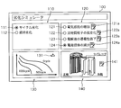
- FIG. 5 is a schematic diagram showing an example of the interface screen 100.
- the interface screen 100 shown in FIG. 5 shows an example of a screen displayed on the display unit 25 of the client device 20 after the client device 20 accesses the server device 10 and is authenticated as a legitimate user. ..
- the client device 20 communicates with the server device 10 and acquires data for the display screen from the server device 10, so that the interface screen 100 as shown in FIG. 5 can be displayed on the display unit 25.
- the interface screen 100 is a screen provided with various display fields and operation buttons arranged as components of the UI (User Interface), and is configured to accept operations by the user through the operation unit 24.
- UI User Interface
- the interface screen 100 shown as an example in FIG. 5 has a selection field 110 that accepts selection of cycle deterioration or deterioration over time, a selection field 120 that accepts selection of deterioration mechanism, a display field 130 that displays a calculation process during simulation, and battery information.
- the input field 140 for accepting the input of is provided.
- the selection field 110 includes a radio button 111 selected when giving a simulation execution instruction for cycle deterioration, and a radio button 112 selected when giving a simulation execution instruction for aging deterioration.
- the example of FIG. 5 shows a state in which the radio button 111 instructing the simulation of cycle deterioration is selected.
- the radio buttons 112 may be selected, or both the radio buttons 111 and 112 may be selected.
- the selection field 120 is selected when the deterioration mechanism of the power storage device is specified as an increase in electrical resistance, an isolation of active material particles, a decrease in conductivity of an electrolytic solution, and a decrease in charge carriers. It includes 124.
- the example of FIG. 5 shows a state in which the radio button 124, which specifies the reduction of charge carriers, is selected as the deterioration mechanism.
- any one of the radio buttons 121 to 123 may be selected, or two or more of the radio buttons 121 to 124 may be selected.
- edit buttons 121a to 124a are arranged corresponding to the radio buttons 121 to 124. When the edit buttons 121a to 124a are operated, the setting screen for accepting the setting change of various parameters is displayed for the corresponding deterioration mechanism.
- the calculation process during the simulation is displayed in the display field 130.
- the calculation process in the case of simulating cycle deterioration and aging deterioration for the decrease of charge carriers is shown by a graph.
- numerical data indicating the calculation process may be displayed.
- a download button 131 is arranged in the display field 130 so that the simulation result can be downloaded.
- the simulation result may be a graph or numerical data.
- the simulation results may be provided by a mathematical model.
- the mathematical model represents a model in which the deterioration process of the power storage device is mathematically described using algebraic equations, differential equations, and characteristic parameters, and is a model obtained by executing a simulation.
- Mathematical models include, for example, MATLAB (registered trademark), Amesim (registered trademark), TwinBiller (registered trademark), MATLAB & Simulink (registered trademark), Sampler (registered trademark), ANSYS (registered trademark), Abaqus (registered trademark), and Moderna. It is provided in the form of libraries, modules, etc. used in commercially available numerical analysis software such as (registered trademark), VHDL-AMS (registered trademark), C language, C ++, Java (registered trademark), or programming languages.
- an edit button 141 for editing information (battery information) of the power storage device is arranged in the input field 140.
- the client device 20 causes the display unit 25 to display a reception screen for receiving battery information.
- the client device 20 transmits the received battery information to the server device 10.
- the server device 10 registers the battery information received from the client device 20 in the battery table of the storage unit 12.
- the battery information is received through the input field 140.
- battery information is prepared in advance for each type and model number of the power storage device, and the battery information may be automatically set by accepting selection for the type and model number of the power storage device.
- the server device 10 When various conditions are set through the interface screen displayed on the display unit 25 of the client device 20, the server device 10 starts a simulation of deterioration of the power storage device.
- the server device 10 executes a simulation of deterioration using a physical model of a battery.
- the physical model represents a first-principles model, and is a model that expresses a phenomenon inside a power storage device by a mathematical formula or the like in accordance with an established natural phenomenon (physical law or chemical law).
- the physical model is also called a white box. Since it is considered difficult among those skilled in the art to express the deterioration mechanism of a power storage device by a physical model, deterioration simulation using the physical model has not been performed so far.
- the physical model used for the simulation of deterioration is a physical model represented by the Newman model.
- the Newman model assumes that homogeneous, single-diameter spheres are closely aligned at each of the positive and negative electrodes.
- the Newman model is described by the Nernst-Planck equation, the charge conservation equation, the diffusion equation, the Butler-Volmer equation, and the Nernst equation described below.
- the Nernst-Planck equation is an equation for solving ion electrophoresis and ion diffusion in an electrolyte or a porous electrode, and is expressed by the following equation.
- i l is the liquid phase current density (A / m 2 )
- ⁇ l and eff are the liquid phase effective conductivity (S / m)
- ⁇ l is the liquid phase potential (V)
- R is the gas constant (J / m).
- T is temperature (K)
- F is the Faraday constant (C / mol)
- f is the activity coefficient
- t + is a cation transport number
- Itot is the reaction current density per volume (A / m 3 ).
- the liquid-phase effective conductivity ⁇ l, eff is the apparent conductivity in the porous body, and is often expressed as a function of the liquid-phase bulk conductivity and the solid-phase volume ratio ⁇ s .
- the charge conservation formula is a formula that expresses electron conduction in active material particles and a current collector foil, and is expressed by the following formula.
- i s is the solid phase current density (A / m 2)
- ⁇ s is the solid phase potential (v)
- sigma s is the solid phase conductivity (S / m)
- i tot the reaction current density per volume A / m 3 ).
- the diffusion equation is an equation that expresses the diffusion of the active material in the active material particles, and is expressed by the following equation.
- c s is the charge carrier concentration in the solid phase (mol / m 3 )
- t is the time (s)
- D s is the diffusion coefficient in the solid phase (m 2 / s).
- the Butler-Volmer equation is an equation that expresses the activation overvoltage in the charge transfer reaction that occurs at the interface between the solid phase and the liquid phase
- the Nernst equation is the definition equation of the open circuit potential, which are expressed by the following equations.
- i loc is the reaction current density (A / m 2 )
- io is the exchange current density (A / m 2 )
- ⁇ a and ⁇ c are the transition coefficients of the oxidation reaction and the reduction reaction
- ⁇ is the activation overvoltage.
- V E eq is the equilibrium potential (V)
- E 0 is the standard equilibrium potential (V)
- z is the valence
- a Ox is the oxidizing agent concentration (mol / m 3 )
- a Red is the reducing agent concentration (mol / m /).
- m 3 As the Butler-Volmer equation and the Nernst equation, alternative equations modified based on experimental values are often used.
- the exchange current density may be made a function of the charge carrier concentration or the ion concentration, or the SOC and the measured data of the open circuit potential may be used as the open circuit potential.
- the open circuit potential In particular, in a lithium ion secondary battery, measured data of SOC and open circuit potential are often used, so a description will be added later.
- Each parameter in the above-mentioned equations 1 to 4 may be a function of other physical values.
- Equation 5 shows the relational expression between the charge carrier concentration in the solid phase and the charge carrier flux involved in the charge transfer reaction on the surface of the active material particles.
- r 0 represents the radius (m) of the active material particles
- J s is the flux of the charge carrier (mol / m 2 s).
- J s is the amount of charge carriers per unit area and unit time that is annihilated by the charge transfer reaction.
- Equation 6 is an equation expressing the relationship between the flux J s of the charge carrier and the reaction current density i loc .
- Equation 7 is an equation expressing the relationship between the reaction current density i loc and the reaction current density i tot per volume.
- S v represents the surface area per unit volume, that is, the specific surface area (m 2 / m 3 ).
- S v may be expressed as a function of the radius r 0 of the active material particle.
- FIG. 6 is a graph showing the relationship between the charge carrier concentration in the solid phase and the open circuit potential (OCP) in a typical positive electrode material.
- the horizontal axis of the graph is the dimensionless charge carriers is defined by the number 8 concentration theta, it is a function of charge carrier concentration c s.
- the vertical axis of the graph is the open circuit potential (OCP).
- the open circuit potential OCP of the positive electrode is expressed as a function of the dimensionless charge carrier concentration ⁇ in the positive electrode.
- the open circuit potential OCP of the negative electrode is expressed as a function of the nondimensionalized charge carrier concentration ⁇ in the negative electrode.
- the control unit 11 may use different open-circuit potential OCP values for discharging and charging.
- OCP open circuit potential
- FIG. 7 is a graph showing the relationship between the non-dimensionalized charge carrier concentration ⁇ of the electrode material having a high energy density and the open circuit potential OCP.
- the horizontal axis of the graph is the non-dimensionalized charge carrier concentration ⁇
- the vertical axis is the open circuit potential OCP.
- the value of the open circuit potential OCP differs between charging and discharging.
- Such properties are called OCP hysteresis or OCP history phenomena and are often found in electrode materials with high energy densities.
- the control unit 11 calculates such an electrode material, a precise simulation can be realized by using different open circuit potential OCP values between the time of discharge and the time of charge.
- the Newman model is shown as an example of the physical model of the lithium ion battery.
- a single particle model may be used in which the electrodes are represented by a single active particle.
- the non-patent document "Single-Particle Model for a Lithium-Ion Cell: Thermal Behavior, Meng Guo, Godfrey Sikha, and Ralph E. White, Journal of The Electrochemical Society, 158 (2) 122- The model disclosed in "132 (2011)" can be referred to.
- a model other than the physical model, such as an equivalent circuit model or a polynomial model, may be used instead as long as it expresses the charge / discharge characteristics.
- system identification that estimates the model from the measured input / output data may be used.
- the system identification may be black box modeling that estimates the model only from the input / output data, and when a part of the system structure is known, the known system structure is reflected and the model is estimated based on the input / output data. Gray box modeling may be performed.
- the polynomial model for example, the non-patent document “Modeling the Dependence of the Discharge Behavior of a Lithium-Ion Battery on the Environmental Temperature, Ui Seong Kim, a Jaesin Yi, a Chee Burm Shin, Tae The model disclosed in "Journal of The Electrochemical Society, 158 (5) 611-618 (2011)” can be referred to.
- the deterioration mechanism of the power storage device As the first deterioration mechanism, an increase in electrical resistance in each element constituting the power storage device will be described.
- the deterioration mechanism due to an increase in electrical resistance is a phenomenon in which the internal resistance of a battery increases due to an increase in the resistivity of an electrolytic solution or an electron conductive member, and the capacity of the battery decreases.
- the factors that increase the electrical resistance are (positive electrode, negative electrode) ⁇ (peeling between the current collector foil and the electrode, disconnection of the conductive path of the conductive auxiliary agent, formation of a resistor film).
- FIG. 8 is an explanatory diagram for explaining the peeling between the current collector foil and the electrode.
- the current collector foil and the electrode positive electrode or negative electrode
- the electrical resistance between the current collector foil and the electrode is relatively small.
- the current collecting foil and the electrode do not have a good bondability, cracks are formed between the particles (active material particles constituting the electrode) due to the expansion and contraction of the particles (active material particles constituting the electrode), the adhesion is lowered, and the particles are separated. ..
- the path through which the current flows decreases and the electrical resistance increases.
- FIG. 9 is an explanatory diagram for explaining the disconnection of the conduction path of the conductive auxiliary agent.
- the conductivity is maintained by adding a small amount of a conductive conductive auxiliary agent such as acetylene black.
- the conductive auxiliary agent itself is cut due to the expansion and contraction of the particles (active material particles constituting the electrode) due to charging and discharging, and the contact between the conductive auxiliary agent and other conductive auxiliary agents, active material particles, etc. is maintained. It may disappear. Alternatively, the conductive auxiliary agent may disappear due to a chemical reaction. As a result, the path through which the current flows decreases and the electrical resistance increases.
- FIG. 10 is an explanatory diagram illustrating the formation of the resistor coating.
- a film of a resistor is formed on the surface of the active material particles as the battery is charged and discharged.
- a film composed of a compound composed of an organic substance and lithium ions in the electrolytic solution is formed.
- Such a coating is inferior in conductivity and therefore has increased electrical resistance.
- the control unit 11 of the server device 10 calculates, for example, the speed at which the electrical resistance increases, that is, the speed at which the electrical conductivity decreases, according to the following equation (9) or (10).
- r cycle and res represent the speed (S / m / number of cycles) at which the electric conductivity decreases depending on the number of cycles.
- r cycle, res ⁇ 0. k 0, res is the reaction rate constant, for example a function of the number of cycles.
- E a0, res represents the activation energy (J / mol) of cycle deterioration, and is a coefficient representing the influence of temperature.
- i is the current density (A / m 2 ), and
- the magnitude of the current density i is a coefficient related to the expansion / contraction rate of the electrode and representing a strain rate-dependent fracture phenomenon such as creep.
- ⁇ res is a constant.
- rt and res represent the speed at which the electric conductivity decreases with the elapsed time (S / m / s).
- rt, res ⁇ 0.
- k 1 and res are reaction rate constants, for example a function of time.
- k 1, res may be defined by any function based on experimental data.
- E a1 and res represent the activation energy (J / mol) of deterioration over time, and are coefficients representing the influence of temperature.
- ⁇ t is the elapsed time (s).
- the values of k 1, res and E a 1, res may be input by the user or may be preset in the server device 10.
- ⁇ s (N + 1) is expressed by the equation of number 11 which is the sum of ⁇ s (N), the cycle deterioration rate, and the aging deterioration rate of one cycle.
- r cycle, res ⁇ 0 and rt , res ⁇ 0 are typically ⁇ s (N + 1) ⁇ s (N), and the conductivity decreases with increasing number of cycles and the passage of time. ..
- the configuration in which the speed at which the electric conductivity decreases is calculated by the equations of the equations 9 and 10, but the arithmetic equation is merely an example and can be freely modified based on the experimental results and literature data. You may.
- the control unit 11 may calculate the rate at which the electrical resistance increases using the number 12 as a function of the upper and lower limits of the SOC.
- the upper limit and the lower limit of the SOC represent the upper limit and the lower limit in the usage range of the battery.
- the control unit 11 can calculate the speed at which the electrical resistance increases depending on the number of cycles by the number 12 multiplied by a function having the upper limit value SOC max and the lower limit value SOC min of the SOC as arguments.
- the upper limit value SOC max and the lower limit value SOC min values may be input by the user or may be preset in the server device 10. In many cases, it is known that the higher the value of (SOC max- SOC min ), the faster the rate of increase in electrical resistance. Therefore, there is a function in which the reaction speed increases as (SOC max- SOC min ) increases. It is preferable to be used.
- k 0, res , E a0, res , ⁇ res , k 1, res , E a1, res , SOC max , and SOC min were used in the velocity equations that determine the increase in electrical resistance.
- different values may be used for the positive electrode and the negative electrode with respect to peeling between the current collector foil and the electrode, breaking the conduction path of the conductive auxiliary agent, and forming a resistor film. Alternatively, some or all of these values may be the same, if desired. These values may be different in the charging process and the discharging process.
- the deterioration mechanism due to the isolation of the active material particles is that the active material particles crack due to repeated expansion and contraction due to charging and discharging, the area where the charge carrier cannot be removed and inserted gradually increases, and the charge carrier of the active material particles is stored and released. This is a phenomenon in which the number of places that can be performed decreases and the amount of electricity that can be stored, that is, the battery capacity decreases. Occlusion is a phenomenon in which charge carriers are retained in a solid phase, that is, in active material particles. Release is a phenomenon in which charge carriers are discharged out of active material particles.
- the control unit 11 of the server device 10 calculates the speed at which the isolation of the active material particles progresses by the formula of the equation 13 or 14.
- r cycle and iso represent the rate (1 / number of cycles) at which the isolation of the active material particles progresses depending on the number of cycles.
- k 0, iso is the reaction rate constant, for example a function of the number of cycles.
- E a0, iso represents the activation energy (J / mol) of cycle deterioration, and is a coefficient representing the influence of temperature.
- i is the current density (A / m 2 ).
- the magnitude of the current density i is a coefficient related to the expansion / contraction rate of the electrode and representing a strain rate-dependent rupture phenomenon such as creep or crack growth.
- ⁇ iso is a constant.
- the values of k 0, iso , E a0, iso , and ⁇ iso may be input by the user or may be preset in the server device 10.
- rt and iso represent the rate at which the isolation of the active material particles progresses with the elapsed time (1 / s).
- rt, iso ⁇ 0.
- k 1 and iso are reaction rate constants, for example a function of time.
- k 1, iso may be defined by any function based on experimental data.
- E a1 and iso represent the activation energy (J / mol) of deterioration over time, and are coefficients representing the influence of temperature.
- ⁇ t is the elapsed time (s). When the stress inside the battery is low, isolation rarely progresses only with time, but it cannot be ignored when it is in a high stress state due to strong external restraint.
- the values of k 1, iso and E a 1, iso may be input by the user or may be preset in the server device 10.
- ⁇ s (N + 1) is the number 15 obtained by adding the cycle deterioration rate and the aging deterioration rate of one cycle to ⁇ s (N). It is expressed by the formula of.
- the reason why the storage device deteriorates when the solid-phase volume ratio ⁇ s of the active material particles decreases that is, the number of places where the charge carrier can be occluded in the storage device decreases, and the amount of electricity that can be stored, that is, the electric capacity decreases. ..
- the decrease in electrical capacity will be described using the minimum and maximum concentrations of c smin and c smax of the occluded charge carriers.
- the maximum concentration is at the end of discharge, and the minimum concentration is at full charge.
- the volume required to calculate the concentration of these charge carriers is the volume of the phase in which the occluded charge carriers can exist.
- the apparent volume of the electrode for example, coating area x coating thickness
- the solid-phase volume ratio of the active material particles in the electrode at the time of manufacture is ⁇ s0
- the volume of the phases that can is V app ⁇ s0.
- the battery capacity at the time of manufacture is Q 0 (C or Ah)
- the configuration for calculating the rate at which the isolation of the active material particles progresses as a function of the number of cycles or the elapsed time has been described.
- the control unit 11 uses the same equation as the equation 12 factorized by the function of the upper and lower limits of the SOC when the energization direction is switched, and the isolation of the active material particles proceeds. You may calculate the speed to do.
- the upper limit value SOC max and the lower limit value SOC min values may be input by the user or may be preset in the server device 10. In many cases, it is known that the larger the value of (SOC max- SOC min ), the faster the isolation progresses. Therefore, the function that the reaction speed increases as (SOC max- SOC min ) increases. It is preferable to be used.
- the total amount of electricity may be used instead of the number of cycles.
- the deterioration mechanism due to the decrease in conductivity in the electrolytic solution is the decrease in conductivity due to the disappearance of charge carriers, the decrease in conductivity due to the generation of minute bubbles in the electrode, the change in the molecular structure of solvation, the clogging of the separator, etc. This is a phenomenon in which the resistivity of the electrolytic solution increases, the internal resistance of the battery increases, and the capacity decreases. Charge carrier loss occurs primarily when a resistor coating is formed on the surface of the active material particles.
- FIG. 11 is a graph showing the relationship between the lithium ion concentration in the electrolytic solution and the ionic conductivity.
- the horizontal axis of the graph shown in FIG. 11 shows the lithium ion concentration in the electrolytic solution, and the vertical axis shows the ion conductivity.
- the relationship between the lithium ion concentration in the electrolytic solution and the ionic conductivity is often as shown in FIG.
- the control unit 11 of the server device 10 can calculate the rate of decrease in conductivity by the same function as in equations 5 and 6.
- the control unit 11 may calculate the rate of decrease in conductivity using the same equation as in Equation 8 factorized by the functions of the upper and lower limits of SOC.
- the conductivity of the ions may be changed.
- the reason why the lithium ion concentration of the electrolytic solution decreases is that the electrolyte salt is precipitated as an insoluble matter due to the product of the oxidation reaction of the electrolytic solution at the positive electrode in a very small amount. As a result, a reaction that traps more lithium ions than the number of electrons consumed in the reduction decomposition of the electrolytic solution at the negative electrode has occurred. As this reaction proceeds, the lithium ion concentration in the electrolytic solution gradually decreases, leading to a decrease in conductivity.
- the deterioration mechanism due to the decrease in charge carriers is a phenomenon in which ions in the electrolytic solution disappear due to a side reaction on the surface of the electrode during charging.
- a lithium ion battery when the lithium ion in the electrolyte solution enters the graphite (i.e. during charging), the main reaction - in addition to (Li + + e + 6C ⁇ LiC 6), and the reaction LiC 6 and an organic substance A side reaction occurs that adheres to the surface of the electrode active material particles as a resistor film.
- a main reaction is reversible reaction, when a voltage is applied in the reverse, Li ⁇ Li + + e - of the reaction takes place, side reactions are irreversible. That is, the lithium ion once formed as a resistor coating cannot participate in charging / discharging thereafter, and the capacity decreases.
- the fourth deterioration mechanism is caused by a decrease in the lithium ion concentration of the electrolytic solution, and does not mean that the electrode material is deteriorated. That is, the fourth deterioration mechanism has room for reuse after dismantling and cleaning.
- the fourth degradation mechanism is known to be accelerated by both time and cycle in the case of lithium-ion batteries.
- P is a substance that is the source of by-products.
- x: (1-x) is the stoichiometric ratio of the main reaction: the side reaction, but it is usually (1-x) / x ⁇ 1, and the stoichiometric coefficient of the side reaction is very small.
- Lithium ions which are obtained by multiplying the stoichiometric coefficient of the side reaction by the current density and the surface area of the electrode and dividing by the Faraday constant, disappear from the electrolytic solution.
- the amount of Li + disappeared in the liquid phase is J Li + (mol / m 2 s)
- x may be a function of the upper limit value SOC max, the lower limit value SOC min , the temperature T, and the current density i as appropriate. For example, it may be a function as described in Equation 20.
- h is an arbitrary function defined to fit the experimental data. Note that 0.0 ⁇ x ⁇ 1.0.
- the decrease in charge carriers involved in charging and discharging in the fourth deterioration mechanism is related to the formation of a resistor coating in the first deterioration mechanism and the decrease in conductivity in the electrolytic solution in the third deterioration mechanism. That is, the cause is that the lithium ions in the electrolytic solution are not used due to the irreversible reaction and are deposited on the electrode surface. In the simulation of the present application, it is possible to correlate and calculate these phenomena, which have been treated separately in the past.
- Equation 21 M is the molecular weight (kg / mol) of the coating substance.
- Equation 22 represents the total amount (mol) of lithium ions lost from the electrolytic solution due to the formation of a film over the surface area S (m 2 ) of the electrode active material particles up to time t (s).
- Equation 23 The ohm overvoltage generated by the resistor coating is expressed as Equation 23.
- r film is the resistivity ( ⁇ m 2 ) of the resistor coating.
- FIG. 12 is a flowchart illustrating a procedure of processing executed by the server device 10 and the client device 20.
- the control unit 21 of the client device 20 receives the data for the display screen transmitted from the server device 10 after the user authentication, and displays the interface screen 100 on the display unit 25 (step S101).
- the control unit 21 accepts the simulation conditions through the interface screen 100 displayed on the display unit 25 (step S102).
- the interface screen 100 accepts, for example, selection of cycle deterioration or deterioration over time, selection of deterioration mechanism, and input of battery information.
- the control unit 21 transmits the simulation conditions received through the interface screen 100 to the server device 10 through the communication unit 23 (step S103).
- the server device 10 receives the simulation conditions transmitted from the client device 20 in the communication unit 13 (step S104).
- the control unit 11 of the server device 10 executes the simulation based on the simulation conditions received through the communication unit 13 (step S105). At this time, the control unit 11 selects a simulation program corresponding to the simulation conditions and applies the simulation conditions to the selected simulation program to simulate the deterioration of the power storage device.
- the control unit 11 may store the simulation condition received in step S104 in the storage unit 12 in association with the user ID input at the time of user authentication.
- the control unit 11 transmits the calculation result to the client device 20 through the communication unit 13 (step S106).
- step S106 each time a value to be calculated in a certain time step or a certain cycle (electrical resistance for each component, volume ratio of isolated region, diffusion coefficient or ionic conductivity of electrolytic solution, expansion rate of battery, etc.) is obtained. , The calculation result may be transmitted to the client device 20 at any time.
- the client device 20 receives the calculation result transmitted from the server device 10 in the communication unit 23 (step S107).
- the control unit 21 of the client device 20 displays the received calculation result in the display field 130 of the interface screen 100 as the calculation process during the simulation (step S108).
- the user can grasp whether or not the simulation by the server device 10 is completed by referring to the calculation process displayed in the display field 130.
- control unit 21 transmits a download request for the simulation result to the server device 10 through the communication unit 23 (step S109).
- the server device 10 When the server device 10 receives the download request from the client device 20 (step S110), the server device 10 transmits the simulation result to the client device 20 (step S111).
- the simulation result transmitted by the server device 10 in step S111 was compared with the value of the electric resistance for each component, the volume ratio of the isolated region, the diffusion coefficient or ionic conductivity of the electrolytic solution, the reduced amount of charge carriers, and the initial state. It is data showing how the expansion rate of the battery changes with the elapsed time and the number of cycles.
- the simulation result may be numerical data in three columns of elapsed time, number of cycles, and physical value. Alternatively, it may be a graph, contour diagram or moving image generated from numerical data.
- the file format to be downloaded may be selected by the user depending on the numerical analysis software or programming language used by the user.
- the client device 20 receives the simulation result transmitted from the server device 10 in the communication unit 23 (step S112).
- the control unit 21 of the client device 20 causes the display unit 25 to display the received simulation result (step S113). Knowing the value of the electrical resistance of each component and the diffusion coefficient or ionic conductivity of the electrolytic solution, the calorific value at the time of energization can be calculated, so that the client can perform, for example, a temperature simulation. Therefore, cooling design and heat management design can be performed. Knowing the volume ratio of the isolated region and the reduced amount of charge carriers, the deterioration of the electrode material can be known, so that the client can predict, for example, the life cycle and the reuse rate. Knowing the expansion coefficient of the battery as compared to the initial state enables the client to design the strength of, for example, a module case or a battery can housing.
- Expansion of the battery due to deterioration includes expansion due to gas generation inside the battery, volume expansion due to cracking of the electrode, and expansion / contraction of the electrode due to charging / discharging.
- expansion due to gas generation and volume expansion due to cracking of the electrode are irreversible expansion and contraction that become larger than the original volume by one charge and discharge.
- the expansion and contraction of the electrode accompanying charge and discharge is a reversible expansion and contraction that returns to the original volume after performing one charge and discharge.
- the formula expressing the expansion can be, for example, several 24 to several 26.
- Equation 24 is an equation expressing the expansion due to gas generation as a function of the temperature T. That is, since the vapor pressure rises as the temperature rises, evaporation of the electrolytic solution and desorption of gas from the electrodes are likely to occur.
- alpha crack coefficient of linear expansion of the original volume by the electrode cracking epsilon s0 effective active material particle volume fraction during manufacture of the electrode
- epsilon s is the effective active material particle volume ratio of the electrode at any time.
- the effective active material particle volume ratio is the volume ratio of the non-isolated portion of the volume of the solid portion of the electrode.
- the number 26 represents the total linear expansion coefficient, and is a function with the expansion due to gas generation and the expansion due to electrode cracking as arguments.
- the expansion formula can be changed as appropriate depending on the battery type and battery material, and is not limited to the above-mentioned number 24 to number 26.
- FIG. 13 is a graph showing the change over time in the expansion coefficient.
- the horizontal axis of the graph shown in FIG. 13 represents time (or the number of cycles), and the vertical axis represents the coefficient of expansion.
- the expansion rate of the battery is the sum of the component that monotonically increases while gradually decreasing and the component that expands and contracts with charging and discharging.
- the former is an irreversible (plastic) expansion and the latter is a reversible (elastic) expansion. Irreversible expansion is given to increase as a function of time and number of cycles, and the relationship between expansion rate and elapsed time and number of cycles should be obtained experimentally.
- the expansion coefficient by a geometric progression with the elapsed time and the number of cycles as arguments. For example, assuming that the increase in the expansion rate in one cycle is r (typically 0 ⁇ r ⁇ 1), the expansion rate after the N cycle is represented by the equation 27 with ⁇ 0 as a constant.
- the deterioration simulation model may include a stress strain model and a fatigue model. It is known that most of the electrode materials change in volume with charge and discharge. In particular, in the electrode material of a lithium ion battery, the volume change due to the removal and insertion of lithium in the charge carrier is remarkable. Normally, since the battery is restrained by a resin material, a metal material, high-tensile steel, or the like, a large internal stress is generated when the electrode material expands, and minute cracks (cracks) may occur in the active material particles. This crack causes the isolation of the active material particles described above. Therefore, a design that does not increase the stress in the active material particles is desired.
- the part that calculates the electrochemical of this model is connected to the electrical network of the numerical analysis software, and the part that calculates the stress strain is connected to the commercially available numerical analysis software (such as structural analysis simulation software of the finite element method). May be good. This makes it possible to calculate the deterioration and stress strain of the battery while simultaneously coupling them.
- the deterioration simulation model may include a heat transfer model. Batteries with advanced deterioration, especially batteries with increased electrical resistance and decreased conductivity in the electrolytic solution, tend to generate a large amount of heat. In general, the higher the temperature, the faster the deterioration progresses, and temperature control is also an important factor in suppressing the deterioration of the battery.
- the part that calculates the electrochemical of this model may be connected to the electric network of the numerical analysis software, and the part that calculates the heat may be connected to the thermal network calculation part of the commercially available numerical analysis software. This makes it possible to calculate the deterioration and heat generation of the battery while simultaneously coupling them.
- the deterioration of the power storage device can be simulated in consideration of the deterioration mechanism, and the simulation result can be provided to the user. If necessary, a mathematical model obtained as a result of simulating the deterioration of the power storage device can be provided to the user. Therefore, in the client device 20, the power storage device is used under desired conditions by using the mathematical model downloaded from the server device 10. Alternatively, the simulation result of the system including the power storage device can be acquired. The client device 20 may download the simulation program used for calculating the simulation result from the server device 10.
- the simulation program downloaded to the client device 20 When using the simulation program downloaded to the client device 20, it may be a requirement to communicate with the server device 10 and receive user authentication. At that time, the simulation conditions input to the client device 20 may be transmitted to the server device 10.
- a wound lithium ion battery in which the electrolyte is a liquid is taken as an example.
- the simulation method of the present application is not limited to battery types such as all-solid-state lithium-ion batteries, bipolar lithium-ion batteries (electrodes connected in series electrically), zinc air batteries, sodium ion batteries, and lead batteries. Can be applied.
- a mode in which a simulation is performed by communication between the server device 10 and the client device 20 is illustrated.
- the server administrator may provide the simulation program to the client user by means of a storage medium such as a DVD-ROM, and the simulation may be performed locally on the client terminal.
- a download format via communication may be used. That is, when the control unit 21 of the client device 20 executes the simulation program, the client device 20 receives the selection information regarding the deterioration mechanism of the power storage device, and executes the deterioration simulation of the power storage device using the selected deterioration mechanism. , It is configured to function as a development support device of the present application that outputs simulation results.
Landscapes
- Engineering & Computer Science (AREA)
- Manufacturing & Machinery (AREA)
- Chemical & Material Sciences (AREA)
- Chemical Kinetics & Catalysis (AREA)
- Electrochemistry (AREA)
- General Chemical & Material Sciences (AREA)
- Physics & Mathematics (AREA)
- Theoretical Computer Science (AREA)
- Computer Hardware Design (AREA)
- Evolutionary Computation (AREA)
- Geometry (AREA)
- General Engineering & Computer Science (AREA)
- General Physics & Mathematics (AREA)
- Secondary Cells (AREA)
- Charge And Discharge Circuits For Batteries Or The Like (AREA)
Abstract
L'invention concerne un dispositif d'aide au développement qui comprend : une unité de réception qui, après authentification de l'utilisateur au niveau d'un dispositif terminal, reçoit du dispositif terminal des informations de sélection concernant un mécanisme de dégradation pour un dispositif de stockage d'énergie ; une unité d'exécution de simulation qui, sur la base des informations de sélection reçues, simule la dégradation du dispositif de stockage d'énergie à l'aide du mécanisme de dégradation sélectionné ; et une unité d'émission qui envoie au dispositif terminal des résultats de simulation provenant de l'unité d'exécution de simulation ou d'un programme de simulation qui est destiné à être exécuté lorsque la dégradation du dispositif de stockage d'énergie est simulée.
Priority Applications (3)
| Application Number | Priority Date | Filing Date | Title |
|---|---|---|---|
| EP20777965.3A EP3951995A4 (fr) | 2019-03-28 | 2020-03-25 | Dispositif d'aide au développement, procédé d'aide au développement et programme informatique |
| CN202080025156.9A CN113646947A (zh) | 2019-03-28 | 2020-03-25 | 开发支援装置、开发支援方法以及计算机程序 |
| US17/598,727 US20220188481A1 (en) | 2019-03-28 | 2020-03-25 | Development support device, development support method, and computer program |
Applications Claiming Priority (4)
| Application Number | Priority Date | Filing Date | Title |
|---|---|---|---|
| JP2019-064218 | 2019-03-28 | ||
| JP2019064218 | 2019-03-28 | ||
| JP2020-048369 | 2020-03-18 | ||
| JP2020048369A JP7480541B2 (ja) | 2019-03-28 | 2020-03-18 | 開発支援装置、及び開発支援方法 |
Publications (1)
| Publication Number | Publication Date |
|---|---|
| WO2020196596A1 true WO2020196596A1 (fr) | 2020-10-01 |
Family
ID=72609902
Family Applications (1)
| Application Number | Title | Priority Date | Filing Date |
|---|---|---|---|
| PCT/JP2020/013248 Ceased WO2020196596A1 (fr) | 2019-03-28 | 2020-03-25 | Dispositif d'aide au développement, procédé d'aide au développement et programme informatique |
Country Status (3)
| Country | Link |
|---|---|
| US (1) | US20220188481A1 (fr) |
| EP (1) | EP3951995A4 (fr) |
| WO (1) | WO2020196596A1 (fr) |
Families Citing this family (3)
| Publication number | Priority date | Publication date | Assignee | Title |
|---|---|---|---|---|
| JP7479416B2 (ja) | 2022-03-30 | 2024-05-08 | 本田技研工業株式会社 | 出力制御装置、出力制御方法、及びプログラム |
| US11664670B1 (en) | 2022-08-21 | 2023-05-30 | Element Energy, Inc. | Methods and systems for updating state of charge estimates of individual cells in battery packs |
| US12119700B2 (en) * | 2023-01-20 | 2024-10-15 | Element Energy, Inc. | Systems and methods for adaptive electrochemical cell management |
Citations (8)
| Publication number | Priority date | Publication date | Assignee | Title |
|---|---|---|---|---|
| JPH1114507A (ja) | 1997-06-19 | 1999-01-22 | Denso Corp | 車両シミュレーション装置 |
| JP2014077785A (ja) * | 2012-09-20 | 2014-05-01 | Sekisui Chem Co Ltd | 蓄電池管理装置、蓄電池管理方法及びプログラム |
| WO2014132332A1 (fr) * | 2013-02-26 | 2014-09-04 | 株式会社 日立製作所 | Dispositif et procédé d'estimation de dégradation |
| WO2014155726A1 (fr) * | 2013-03-29 | 2014-10-02 | 株式会社日立製作所 | Procédé d'estimation de caractéristiques de pile, dispositif d'estimation de caractéristiques de pile et programme |
| JP2015215169A (ja) * | 2014-05-07 | 2015-12-03 | カルソニックカンセイ株式会社 | パラメータ算出装置、パラメータ算出方法及びプログラム |
| WO2017002292A1 (fr) * | 2015-06-30 | 2017-01-05 | ソニー株式会社 | Système d'accumulation d'énergie, unité de commande ainsi que procédé de charge et de décharge de batterie d'accumulateurs |
| US20180088181A1 (en) * | 2015-07-02 | 2018-03-29 | Huawei Technologies Co., Ltd. | Apparatus and method for detecting battery state of health |
| WO2018147194A1 (fr) * | 2017-02-07 | 2018-08-16 | 日本電気株式会社 | Dispositif de commande de batterie de stockage, procédé de commande de charge/décharge, et support d'enregistrement |
Family Cites Families (5)
| Publication number | Priority date | Publication date | Assignee | Title |
|---|---|---|---|---|
| JP4893703B2 (ja) * | 2008-07-11 | 2012-03-07 | トヨタ自動車株式会社 | 蓄電装置の劣化表示システムおよび蓄電装置の劣化表示方法 |
| JP5586219B2 (ja) * | 2009-12-25 | 2014-09-10 | 株式会社東芝 | 診断装置、電池パック及び電池価値指標の製造方法 |
| JP5403191B2 (ja) * | 2011-11-08 | 2014-01-29 | 新神戸電機株式会社 | 蓄電池状態監視システム |
| KR102553031B1 (ko) * | 2016-01-14 | 2023-07-06 | 삼성전자주식회사 | 배터리의 상태 추정 장치 및 방법 |
| US10209314B2 (en) * | 2016-11-21 | 2019-02-19 | Battelle Energy Alliance, Llc | Systems and methods for estimation and prediction of battery health and performance |
-
2020
- 2020-03-25 WO PCT/JP2020/013248 patent/WO2020196596A1/fr not_active Ceased
- 2020-03-25 US US17/598,727 patent/US20220188481A1/en active Pending
- 2020-03-25 EP EP20777965.3A patent/EP3951995A4/fr active Pending
Patent Citations (8)
| Publication number | Priority date | Publication date | Assignee | Title |
|---|---|---|---|---|
| JPH1114507A (ja) | 1997-06-19 | 1999-01-22 | Denso Corp | 車両シミュレーション装置 |
| JP2014077785A (ja) * | 2012-09-20 | 2014-05-01 | Sekisui Chem Co Ltd | 蓄電池管理装置、蓄電池管理方法及びプログラム |
| WO2014132332A1 (fr) * | 2013-02-26 | 2014-09-04 | 株式会社 日立製作所 | Dispositif et procédé d'estimation de dégradation |
| WO2014155726A1 (fr) * | 2013-03-29 | 2014-10-02 | 株式会社日立製作所 | Procédé d'estimation de caractéristiques de pile, dispositif d'estimation de caractéristiques de pile et programme |
| JP2015215169A (ja) * | 2014-05-07 | 2015-12-03 | カルソニックカンセイ株式会社 | パラメータ算出装置、パラメータ算出方法及びプログラム |
| WO2017002292A1 (fr) * | 2015-06-30 | 2017-01-05 | ソニー株式会社 | Système d'accumulation d'énergie, unité de commande ainsi que procédé de charge et de décharge de batterie d'accumulateurs |
| US20180088181A1 (en) * | 2015-07-02 | 2018-03-29 | Huawei Technologies Co., Ltd. | Apparatus and method for detecting battery state of health |
| WO2018147194A1 (fr) * | 2017-02-07 | 2018-08-16 | 日本電気株式会社 | Dispositif de commande de batterie de stockage, procédé de commande de charge/décharge, et support d'enregistrement |
Non-Patent Citations (3)
| Title |
|---|
| MENG GUOGODFREY SIKHARALPH E. WHITE: "Single-Particle Model for a Lithium-Ion Cell: Thermal Behavior", JOURNAL OF THE ELECTROCHEMICAL SOCIETY, vol. 158, no. 2, 2011, pages 122 - 132 |
| See also references of EP3951995A4 |
| UI SEONG KIMJAESHIN YICHEE BURM SHINTAEYOUNG HANB AND SEONGYONG PARK: "Modeling the Dependence of the Discharge Behavior of a Lithium-Ion Battery on the Environmental Temperature", JOURNAL OF THE ELECTROCHEMICAL SOCIETY, vol. 158, no. 5, 2011, pages 611 - 618 |
Also Published As
| Publication number | Publication date |
|---|---|
| EP3951995A4 (fr) | 2022-10-26 |
| US20220188481A1 (en) | 2022-06-16 |
| EP3951995A1 (fr) | 2022-02-09 |
Similar Documents
| Publication | Publication Date | Title |
|---|---|---|
| JP7480541B2 (ja) | 開発支援装置、及び開発支援方法 | |
| CN111505502B (zh) | 基于微观机理的时变循环工况下锂离子电池老化试验方法 | |
| Purkayastha et al. | An integrated 2-D model of a lithium ion battery: the effect of material parameters and morphology on storage particle stress | |
| JP6699795B1 (ja) | シミュレーション方法、シミュレーション装置、及びコンピュータプログラム | |
| CN111999665B (zh) | 一种基于微观机理汽车驾驶工况锂离子电池老化试验方法 | |
| US10686321B2 (en) | Secondary battery management | |
| Timms et al. | Asymptotic reduction of a lithium-ion pouch cell model | |
| Li et al. | Physics-based CFD simulation of lithium-ion battery under the FUDS driving cycle | |
| CN111665451B (zh) | 一种时变循环工况下的锂离子电池老化测试方法 | |
| WO2020196596A1 (fr) | Dispositif d'aide au développement, procédé d'aide au développement et programme informatique | |
| US11579205B2 (en) | Estimation device, energy storage device, method for estimation, and computer program | |
| CN113794254A (zh) | 一种热管理策略配置方法、装置、计算机设备和存储介质 | |
| WO2020189730A1 (fr) | Procédé, dispositif et programme de simulation | |
| Lim et al. | Efficient electrochemical state of health model for lithium ion batteries under storage conditions | |
| Same et al. | Effect of thermal parameters on behaviour of a lithium-ion battery: simulation study | |
| Nourizadeh et al. | Study on the thermal characteristics of layered NMC cathodes in lithium-ion batteries | |
| Shang et al. | Analytical solution for thermal-diffusion induced stress model and numerical simulation of battery structure during charging-discharging process | |
| Verma et al. | Sensitivity analysis of aging factors for lithium iron phosphate batteries using modified electro-thermal model | |
| CN120370194A (zh) | 锂离子电池日历寿命预测方法和装置、电子设备与存储介质 | |
| CN119623274A (zh) | 一种锂电池寿命预测方法、装置、终端设备及介质 | |
| Bansal et al. | Multiphysics-Informed Machine Learning for Battery Design and Health Monitoring | |
| JP7508847B2 (ja) | 蓄電デバイスの挙動推定方法、挙動推定装置、及びコンピュータプログラム | |
| CN116381512B (zh) | 电池电压计算方法、装置、电子设备及可读存储介质 | |
| JP7651911B2 (ja) | コンピュータプログラム、シミュレーション方法、及びシミュレーション装置 | |
| US20260030393A1 (en) | Methods and systems for scalable physics-based battery pack modeling |
Legal Events
| Date | Code | Title | Description |
|---|---|---|---|
| 121 | Ep: the epo has been informed by wipo that ep was designated in this application |
Ref document number: 20777965 Country of ref document: EP Kind code of ref document: A1 |
|
| NENP | Non-entry into the national phase |
Ref country code: DE |
|
| ENP | Entry into the national phase |
Ref document number: 2020777965 Country of ref document: EP Effective date: 20211028 |