WO2020196907A1 - Dispositif de nettoyage - Google Patents
Dispositif de nettoyage Download PDFInfo
- Publication number
- WO2020196907A1 WO2020196907A1 PCT/JP2020/014422 JP2020014422W WO2020196907A1 WO 2020196907 A1 WO2020196907 A1 WO 2020196907A1 JP 2020014422 W JP2020014422 W JP 2020014422W WO 2020196907 A1 WO2020196907 A1 WO 2020196907A1
- Authority
- WO
- WIPO (PCT)
- Prior art keywords
- adhesive tape
- support shaft
- cleaning device
- tube
- shaft portion
- Prior art date
- Legal status (The legal status is an assumption and is not a legal conclusion. Google has not performed a legal analysis and makes no representation as to the accuracy of the status listed.)
- Ceased
Links
Images




Classifications
-
- A—HUMAN NECESSITIES
- A47—FURNITURE; DOMESTIC ARTICLES OR APPLIANCES; COFFEE MILLS; SPICE MILLS; SUCTION CLEANERS IN GENERAL
- A47L—DOMESTIC WASHING OR CLEANING; SUCTION CLEANERS IN GENERAL
- A47L25/00—Domestic cleaning devices not provided for in other groups of this subclass
- A47L25/005—Domestic cleaning devices not provided for in other groups of this subclass using adhesive or tacky surfaces to remove dirt, e.g. lint removers
-
- A—HUMAN NECESSITIES
- A47—FURNITURE; DOMESTIC ARTICLES OR APPLIANCES; COFFEE MILLS; SPICE MILLS; SUCTION CLEANERS IN GENERAL
- A47L—DOMESTIC WASHING OR CLEANING; SUCTION CLEANERS IN GENERAL
- A47L25/00—Domestic cleaning devices not provided for in other groups of this subclass
-
- B—PERFORMING OPERATIONS; TRANSPORTING
- B65—CONVEYING; PACKING; STORING; HANDLING THIN OR FILAMENTARY MATERIAL
- B65H—HANDLING THIN OR FILAMENTARY MATERIAL, e.g. SHEETS, WEBS, CABLES
- B65H16/00—Unwinding, paying-out webs
-
- B—PERFORMING OPERATIONS; TRANSPORTING
- B65—CONVEYING; PACKING; STORING; HANDLING THIN OR FILAMENTARY MATERIAL
- B65H—HANDLING THIN OR FILAMENTARY MATERIAL, e.g. SHEETS, WEBS, CABLES
- B65H16/00—Unwinding, paying-out webs
- B65H16/005—Dispensers, i.e. machines for unwinding only parts of web roll
-
- B—PERFORMING OPERATIONS; TRANSPORTING
- B65—CONVEYING; PACKING; STORING; HANDLING THIN OR FILAMENTARY MATERIAL
- B65H—HANDLING THIN OR FILAMENTARY MATERIAL, e.g. SHEETS, WEBS, CABLES
- B65H16/00—Unwinding, paying-out webs
- B65H16/02—Supporting web roll
-
- B—PERFORMING OPERATIONS; TRANSPORTING
- B65—CONVEYING; PACKING; STORING; HANDLING THIN OR FILAMENTARY MATERIAL
- B65H—HANDLING THIN OR FILAMENTARY MATERIAL, e.g. SHEETS, WEBS, CABLES
- B65H16/00—Unwinding, paying-out webs
- B65H16/02—Supporting web roll
- B65H16/021—Multiple web roll supports
-
- B—PERFORMING OPERATIONS; TRANSPORTING
- B65—CONVEYING; PACKING; STORING; HANDLING THIN OR FILAMENTARY MATERIAL
- B65H—HANDLING THIN OR FILAMENTARY MATERIAL, e.g. SHEETS, WEBS, CABLES
- B65H18/00—Winding webs
- B65H18/02—Supporting web roll
- B65H18/04—Interior-supporting
-
- B—PERFORMING OPERATIONS; TRANSPORTING
- B65—CONVEYING; PACKING; STORING; HANDLING THIN OR FILAMENTARY MATERIAL
- B65H—HANDLING THIN OR FILAMENTARY MATERIAL, e.g. SHEETS, WEBS, CABLES
- B65H2701/00—Handled material; Storage means
- B65H2701/30—Handled filamentary material
- B65H2701/37—Tapes
- B65H2701/377—Adhesive tape
Definitions
- the present invention relates to a cleaning device, and more particularly, cleaning is performed by using a roll to which an adhesive tape is attached and performing a cleaning operation while adsorbing debris, dust, dust, etc. on the adhesive surface of the adhesive tape. It is about the device.
- a cleaning device that uses an adhesive tape to perform cleaning work while adsorbing lint, lint, hair, hair of dogs and cats, and other dust, debris, dust, etc. on the adhesive surface of the adhesive tape.
- the initial cleaning device using the adhesive tape has a structure in which only one of the adhesive tapes is attached, and in the case of the cleaning device having such a structure, the adhesive tape is placed 360 degrees back and forth from 2 to 2. When it was rotated three times, dust was adsorbed on the entire circumference of the adhesive tape, and the number of new surfaces for further adsorbing the dust and the like was reduced, and when it was rotated, the adsorption force was almost lost.
- Patent Document 2 1-118768 (Patent Document 2), and the like are known.
- a winding roller for sequentially winding the adhesive tape drawn from the adhesive tape roller is provided, and the winding roller is directly contacted with the adhesive tape roller.
- the dust is drawn out from the adhesive tape roller and adheres to the winding roller.
- a cleaning device configured to wind the adhesive tape around the take-up roller has been proposed.
- the adhesive surface of the adhesive tape on which the dust is adsorbed is wound on the winding roller, and the adhesive surface of the adhesive tape on which the dust is adsorbed is on the inside. Since it is taken, the surface of the adhesive tape to which dust or the like does not adhere forms an outer peripheral surface on the surface of the take-up roller, so that it is hygienic in terms of handling and at the same time, a plurality of adhesive tapes are attached. There is an advantage that it is not necessary to make individual perforations and it is not necessary to frequently separate the adhesive tape, but on the other hand, the winding roller is always wound by using an appropriate damping member.
- Patent Document 3 Japanese Patent Application Laid-Open No. 2009-28228 (Patent Document 3) or Japanese Patent Application Laid-Open No. 7-227375 (Patent Document 4) have been proposed in order to improve the technical drawbacks.
- an adhesive tape roller and a take-up roller that winds up the adhesive tape drawn from the adhesive tape roller and to which the dust is attached are used.
- an appropriate power transmission means for example, a belt or a gear train mechanism. It is configured to transmit and rotate the take-up roller.
- the cleaning device is moved when the cleaning operation is repeatedly performed such that the cleaning device is repeatedly slid back and forth on an appropriate surface to be cleaned and gradually moved forward.
- the operating resistance is small, but the number of rotations of the adhesive tape roller increases as the diameter of the adhesive tape roller changes, or if there is a problem that the cost increases due to the complexity of the device or mechanism.
- a fixed ratio of to the number of revolutions of the take-up roller causes a mismatch between the length of the adhesive tape drawn from the adhesive tape roller and the take-up length of the take-up roller, resulting in a mismatch.
- an object of the present invention is to appropriately use the cleaning device when performing cleaning work by adsorbing dust including dust, dirt, hair dust, etc. on the adhesive layer surface of the adhesive tape using the adhesive tape roller.
- the cleaning device is configured to repeatedly perform cleaning work that gradually moves forward while repeatedly sliding back and forth on the surface to be cleaned, despite its simple configuration. Is easy and light, and the operation of attaching and detaching the adhesive tape roller and the winding roller is easy, and even during the cleaning work, the adhesive tape roller and the winding roller Provided is a cleaning device capable of uniformly winding the adhesive tape drawn from the adhesive tape roller straddled between them on the winding roller without slack at all times.
- the cleaning device according to the present invention adopts the following basic technical configuration in order to achieve the above object. That is, as an aspect of the basic technical configuration in the cleaning device according to the present invention, a predetermined long-shaped portion is provided, and a desired handle portion is formed in a part of the long-shaped portion. From the main body frame portion and the desired portion of the main body frame portion in the predetermined elongated portion to the outside in a direction orthogonal to the central axis in the elongated direction in the elongated portion. A first support shaft portion and a second support shaft portion, which are extended and arranged parallel to each other and arranged at a desired interval from each other, are provided, and the first support shaft portion is provided.
- a first auxiliary support tube configured to be arbitrarily detachably fitted and fixed to a paper tube portion provided at the center of the adhesive tape roller on which the adhesive tape is wound rotates in the forward and reverse directions.
- a hollow adhesive tape winding tube configured to wind up the adhesive tape to which dust and dirt drawn from the adhesive tape is attached is attached to the second support shaft portion freely.
- a second auxiliary support tube configured to be arbitrarily detachably fitted and fixed is attached so as to be rotatable in the forward and reverse directions, and the second auxiliary support tube is attached to the second support shaft portion. It is a cleaning device characterized in that a bias force is applied in a desired rotation direction by a coil spring arranged between the second auxiliary support pipes.
- the cleaning device according to the present invention has a simpler structure than the conventional cleaning device of the same type, but the cleaning operation can be performed easily and lightly. It is easy to install and remove the adhesive tape roller and the take-up roller, and even during the cleaning work, the adhesive tape is laid between the adhesive tape roller and the take-up roller. An inexpensive and hygienic cleaning device capable of uniformly winding the adhesive tape drawn out from the roller around the winding roller without sagging at all times can be obtained. That is, the cleaning device according to the present invention is used by attaching the adhesive tape as in the conventional case, but it is not necessary to peel off the adhesive tape on the surface to which the dust adheres, and the dust adheres to the dust.
- the tape can be used continuously to the end, which is very efficient and hygienic. Moreover, in the past, cleaning was mostly done by the housewife, but by being able to clean without getting your hands dirty during cleaning, it is possible for children and the elderly to easily help with cleaning. It is possible to provide a cleaning device.
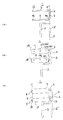
- FIG. 1 is a plan view illustrating an outline of a configuration of a cleaning device according to the present invention.
- FIG. 2 is a partial cross-sectional plane for explaining the outline of the configuration of the first auxiliary support pipe and the second auxiliary support pipe among the constituent parts of the cleaning device in the present invention.
- FIG. 3 is a plan view illustrating the configuration of another specific example of the cleaning device 1 according to the present invention.
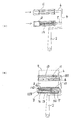
- FIG. 4 is a diagram illustrating a specific example of the configuration of the first auxiliary support tube used in the present invention.
- FIG. 5 is a cross-sectional view showing a state of a configuration including a first support shaft portion 6 in a state where the adhesive tape roller 9 is mounted on the first auxiliary support tube of the cleaning device according to the present invention.
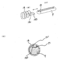
- FIG. 6 is a diagram illustrating a configuration example of a ratchet mechanism for preventing free rotation between the first support shaft portion and the first auxiliary support pipe used in the cleaning device in the present invention.
- FIG. 7 is a diagram illustrating another specific example of the first auxiliary support tube fitted to the first support shaft portion used in the cleaning device according to the present invention.
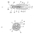
- FIG. 8 is a diagram illustrating a specific example of a second auxiliary support pipe fitted to the second support shaft portion used in the cleaning device according to the present invention.
- FIG. 9 shows a specific example of the second auxiliary support pipe fitted to the second support shaft portion used in the cleaning device in the present invention, and the second support shaft portion and the second auxiliary support pipe.
- FIG. 10 is a diagram illustrating another specific example of a method of attaching a coil spring arranged between the second support shaft portion and the second auxiliary support pipe used in the cleaning device in the present invention.
- FIG. 11 is a diagram illustrating another specific example of a method of attaching a coil spring arranged between the second support shaft portion and the second auxiliary support pipe used in the cleaning device in the present invention.
- FIG. 12 is a diagram illustrating another specific example of a method of attaching a coil spring arranged between the second support shaft portion and the second auxiliary support pipe used in the cleaning device in the present invention. .. FIG. FIG.
- FIG. 13 is a diagram illustrating still another specific example of a method of attaching a coil spring arranged between the second support shaft portion and the second auxiliary support pipe used in the cleaning device in the present invention. is there.
- FIG. 14 is a diagram illustrating an example of a method of transferring the adhesive tape from the adhesive tape roller to the adhesive tape winding tube in the cleaning device according to the present invention.
- FIG. 15 is a side view showing the configuration of the cleaning device in the present invention and a diagram for explaining an example of how to use the cleaning device.
- FIG. 16 is a diagram showing an example of a kit in which an adhesive tape winding tube is built in a paper tube of an adhesive tape roller used in the cleaning device in the present invention.
- FIG. 1 is a plane of the cleaning device 1 according to the first aspect of the present invention, has a predetermined elongated portion 3 in the drawing, and is a part of the elongated portion 3.
- the support shaft portion 7 is provided, and the first support shaft portion 6 is optionally attached to and detached from the paper tube portion provided at the center of the adhesive tape roller 9 on which the adhesive tape 8 is wound.
- a first auxiliary support tube 11 configured to be freely fitted and fixed is rotatably attached in the forward and reverse directions, while the second support shaft portion 7 is pulled out from the adhesive tape roller 9.
- the hollow adhesive tape winding tube 12 configured to wind up the adhesive tape 8 to which the dust adheres and the second auxiliary support tube 13 configured to be arbitrarily detachably fitted and fixed are forward and reverse.
- the second auxiliary support tube 13 is attached so as to be rotatable in the direction, and the second auxiliary support tube 13 is arranged between the second support shaft portion 7 and the second auxiliary support tube 13 as illustrated in FIG.
- the cleaning device 1 is shown which is configured so that a rotation bias force is applied in a desired rotation direction by the coil spring 14.
- FIG. 2 is viewed from above by dividing the first auxiliary support pipe 11 and the second auxiliary support pipe 13 installed in the cleaning device 1 of one specific example in FIG. 1 in half. It is a plan view. That is, in the cleaning device 1 according to the present invention, an adhesive layer is basically formed on the outer peripheral portion of a hollow paper tube 10 having an appropriate inner diameter of a commercially available known adhesive tape 8. Using the adhesive tape roller 9 configured to be wound a plurality of times with the surface facing outward, while performing an appropriate cleaning operation, the adhesive layer surface of the adhesive tape 8 is continuously adsorbed with appropriate dust.
- the inner diameter of the paper tube 10 is not particularly specified, and an arbitrary inner diameter such as 10 to 50 mm is adopted, but in general, the inner diameter is 38 mm in many cases.
- the adhesive tape 8 adsorbing the dust gradually sent out from the adhesive tape roller 9 during the cleaning operation is attached to the first auxiliary support tube 11. Since the cleaning work is not slackened at all between the second auxiliary support tube 13 and the second auxiliary support tube 13, it is possible to avoid a situation in which the adhesive tapes 8 are entangled with each other and become inoperable.
- the adhesive tape 8 can be wound up efficiently, and the state is surely maintained until all of the adhesive tapes 8 laminated on the adhesive tape roller 9 are sent out. That is, this is a problem that, in the prior art, a malfunction phenomenon occurs due to a change in the diameter of the cylindrical body made of the adhesive tape roller 9 and the adhesive tape 8 wound around the adhesive tape winding tube 12. It shows that the points were solved and shown.
- the basic technical configuration is such that when the adhesive tape 8 sequentially pulled out from the adhesive tape roller 9 is wound around the adhesive tape winding tube 12, at least the adhesive tape 8 is in a stationary state.
- a rotational force that rotates the adhesive tape winding tube 12 on the second auxiliary support tube 13 in the direction of winding the adhesive tape 8 so as to apply a desired tension to the adhesive tape 8.
- the bias is configured to be applied at all times, but the rotational force bias is set to a level that does not cause the adhesive tape roller 9 to rotate in the direction in which the adhesive tape 8 is pulled out.
- the adhesive tape winding tube 12 is surely wound by the length of the pulled out adhesive tape 8.
- the second auxiliary support tube 13 is configured to rotate in the winding direction thereof.
- An example of the configuration of the winding mechanism of the adhesive tape 8 in the second support shaft portion 7 according to the present invention is not particularly specified, but for example, as shown in FIG.
- An appropriate coil spring 14 is inserted into the space formed between the second support shaft portion 7 and the second auxiliary support pipe 13, and one end portion 141 of the coil spring 14 is inserted into the second end portion 141. It is desirable to fix the other end 142 of the coil spring 14 to an appropriate portion of the support shaft portion 7 and at the same time to fix the other end 142 of the coil spring 14 to an appropriate portion of the second auxiliary support tube 13.
- the second auxiliary support tube 13 By rotating the auxiliary support tube 13 in a predetermined rotation direction at a constant angle, the second auxiliary support tube 13 is given a rotational bias force that tries to rotate in the opposite direction, and the force is applied.
- the adhesive tape 8 pulled out from the adhesive tape roller 9 by a predetermined length is mounted on the second auxiliary support tube 13, and the adhesive tape winding tube 12 is attached to the adhesive tape 8. This can be done by rotating it in the winding direction.
- the rotational bias force applied to the second auxiliary support tube 13 by itself positively rotates the adhesive tape roller 9 from the adhesive tape roller 9.
- the structure, constituent materials, unit number of turns of the coil, inner diameter of the coil, winding direction, etc. of the coil spring 14 used in the present invention are not specified, and a compression spring or a commercially available compression spring is generally available. Can be used with any so-called compression coil spring.
- the cross-sectional shape of one steel wire is usually a round wire shape, and the diameter thereof is generally within 0.2 mm to 1 mm. Yes, but not specified.
- the coil spring 14 Even when the moving plate described later at any of the left and right ends of the above is taken into consideration, it is possible to obtain the number of windings before and after 25 rotations, and the length in the longitudinal direction is 100, 160, 320 mm. Needless to say, in any of the above cases, the required number of rotations can be set to 25 rotations or more.
- the coil spring 14 usually has a right-handed coil and a left-handed coil, and although any type can be used in the present invention, the above-mentioned rotational bias force is applied to the coil in advance.
- the coil spring 14 is twisted with respect to its central axis in a direction opposite to the desired rotation direction, and at that time, the inner diameter of each coil portion of the coil spring 14 is adjusted.
- the dimensions, shape, and the like of the cleaning device 1 according to the present invention are not particularly limited, and the appearance and shape of the cleaning device 1 disclosed in the present specification show a part of specific examples thereof. Is what you are doing.
- substantially the entire structural portion is composed of a metal material or a synthetic resin material, and in some cases, both materials are combined. It goes without saying that it may be made to be made.
- the cleaning device 1 according to the present invention is made of synthetic resin, it is desirable that a considerable part of the cleaning device 1 is manufactured by integral molding.
- the cleaning device 1 is on one side surface.
- a single main body frame body portion 4 composed of a substantially linear elongated portion 3 and an appropriate portion at an end portion of the main body frame body portion 4 parallel to the central axis 5 of the main body frame body portion 4.
- a handle portion 2 having an appropriate length is provided in each direction.
- the length, width, height, cross-sectional shape, etc. of the main body frame portion 4 and the handle portion 2 are not particularly specified, and the dimensions and shapes are suitable for the operator to easily hold and move by hand. It is desirable to have.
- the handle portion 2 may be provided on an extension line of the central axis 5 of the main body frame portion 4, or as shown in the drawing, the first and second handles are more than the main body frame portion 4.
- the support shaft portions 6 and 7 of the above may be arranged so as to be offset in the direction of the portion extending along the respective central axis lines.
- one end 61, 70 of the first and second support shafts 6, 7 arranged in parallel with each other in the present invention is as shown in a specific example of FIG.
- the other ends 62 and 72 can be free ends.
- the other end portions 62 and 72 are also separately provided as a long body frame body portion 4'(second main body frame body portion 4). It is also possible to have a double-sided configuration by contacting it with').
- the second main body frame portion 4' is attached to the first support shaft portion 6 and the second support shaft portion 7 at appropriate times, respectively, as the first auxiliary.
- the support tube 11 and the second auxiliary support tube 13 are detachably configured with respect to the first support shaft portion 6 and the second support shaft portion 7. It is one of the examples, and in some cases, as shown in FIG. 3B, one end of the second main body frame body 4'is a part of another main body frame body 4. , It may be configured to be swivelable via an appropriate swivel member.
- the mutual arrangement interval of the first and second support shaft portions 6 and 7 and the length in the central axis direction thereof are not specified, but the length in the central axis direction is at least 50 mm or more. Is desirable, and it is desirable that the maximum length is 250 mm or less. This is due to the fact that the widths of commercially available adhesive tapes generally used in the past are mostly 80, 100, 160, and 220 mm.
- the winding circumference of the adhesive tape is mainly 50, 60, 70, 80, 90, and the total length of the adhesive tape is long.
- 50 laps is about 7M (meters)
- 70 laps is about 9M (meters) or more
- 90 laps is about 13M (meters)
- one rotation is about 14cm to 16cm in length.
- the tape will move.
- at least the distance between the central axes of the first support shaft portion 6 and the second support shaft portion 7 is at least half the outer diameter of the adhesive tape roller 9. It is a specific example that it is desirable to set the interval so as to be longer than the total length of the length and the length of half of the outer diameter of the adhesive tape winding pipe 12.
- the first auxiliary support tube 11 is detachably and rotatably fitted and fixed to the first support shaft portion 6, and the adhesive tape roller 9 is detachably attached to the outer surface portion thereof. Moreover, it is fitted and fixed in a non-rotating state.
- the main body 135 of the first auxiliary support tube 11 has an outer diameter made of a paper tube or a material mainly composed of synthetic resin, and has an inner diameter of the paper tube portion 10 used for the adhesive tape roller 9.
- It is composed of a hollow cylindrical body set to be substantially the same as the above, and the length in the central axis direction is greater than the length of the central axis of the paper tube portion 10 used in the adhesive tape roller 9. It is desirable to set it so that it is also long.
- disk-shaped lids 133 and 134 having substantially the same outer diameter as the outer diameter of the cylindrical body 135, respectively,
- the disk-shaped lids 133 and 134 having a central hole 132 formed through the first support shaft 6 at the same time are fixedly arranged in the central portion.
- a plurality of stopper portions 136 made of a rubber material having a predetermined height and size, a synthetic resin having elasticity, or the like are arranged and formed at appropriate portions.
- FIG. 5 shows a state including the second support shaft portion 7 in a state where the desired adhesive tape roller 9 is mounted on the first auxiliary support tube 11 of the cleaning device 1 in the present invention. It is sectional drawing which showed.
- either of the adhesive tape rollers 9 may be used by itself before or while the cleaning work is interrupted. Rotating in a direction also causes another problem, which can be prevented and only when the operator is using the cleaning device 1 to perform the desired cleaning operation in a predetermined direction. It is desirable that a ratchet mechanism for preventing so-called free rotation, which is set to rotate by a predetermined amount, is provided.
- the predetermined direction is preferably the direction in which the adhesive tape 8 is pulled out from the adhesive tape roller 9.
- an appropriate material for example, an appropriate synthetic resin material
- an appropriate synthetic resin material is applied to a part of the outer surface of the first support shaft portion 6.
- one or a plurality of claw portions 66 having an appropriate height made of a metal material are projected radially around the central axis of the first support shaft portion 6, and at the same time, the first auxiliary portion is assisted.
- An appropriate synthetic resin material having a plurality of desired lengths that engage with the claw portion 66 at a portion of the inner wall surface portion of the support tube 11 that faces the portion where the claw portion 66 is arranged and formed.
- the number, height, and the like of the claw portion 66 or the locking piece portion 62 are not particularly limited, but as shown in FIGS. 6 (A) to 6 (C), they may be arbitrarily formed as necessary. It may be formed and arranged. That is, in the above specific example, the adhesive tape roller 9 exerts a positive rotational force given by the cleaning operation depending on the degree of flexural modulus between the claw portion 66 and the locking piece portion 62. Unless it is received, its free rotation will surely be prevented.
- the other specific example of the first auxiliary support tube 11 disclosed in FIG. 7 is functionally substantially the same as the above-described configuration of the first auxiliary support tube 11.
- the weight and strength of the first auxiliary support tube 11 are simultaneously achieved, and the fitting mounting operation and fitting / removing operation of the paper tube 10 of the adhesive tape roller 9 with respect to the first auxiliary support tube 11 are simplified. It makes it possible to make it easier.
- both ends of the first auxiliary support tube 11 are different from those used in the above-mentioned specific example.
- the lids 116 and 117 are fixedly arranged so as to face each other with a desired interval 115 in a state where the central axes of the central hole 118s are aligned with each other, and the predetermined lids 116 are placed in the gaps thereof.
- the two shielding plate portions 110 and 111 having the length of the long portion as the length of the long portion and having a length substantially close to the length of the diameter of the disk-shaped lid 116 and 117 as the length of the short portion are the first
- the discs are arranged in a state of being parallel to each other in the vertical direction via the central axis of the support shaft portion 6 at desired intervals, and the short portions of the two shielding plate portions 110 and 111 are individually arranged.
- the lids 116 and 117 are joined and fixed to the inner wall surface via an appropriate joining means, and at the same time, on the surface of the shielding plate portions 110 and 111 opposite to each other and on the opposite side.
- Each of the shielding plate portions 110 and 111 has a desired height along the center line portion in the elongated direction (that is, the portion facing the center line of the first support shaft portion 6), preferably.
- the vertical wall portions 112 and 113 having a height reaching from the outer surface portions of the respective shielding plate portions 110 and 111 to a position substantially coincide with the outer peripheral edge portion surface of the disk-shaped lids 116 and 117.
- a configuration is adopted in which a plurality of reinforcing members 114 are arranged at appropriate intervals along the joint portion S between the shielding plate portions 110 and 111 and the vertical wall portions 112 and 113, respectively. It is what you are doing.
- the first auxiliary support tube 11 in the specific example according to the present invention is preferably made of a paper material or an appropriate synthetic resin material, and is particularly made of a synthetic resin material. In some cases, it is a cost-effective method to manufacture by the integral molding method. Further, in the above specific example, the outer peripheral surface portions of the shielding plate portions 110 and 111, the shielding plate portions 110 and 111, and the outermost edge surfaces of the vertical wall portions 112 and 113 are covered with the above-mentioned specific examples. It is also a desirable specific example that the plurality of stopper portions 136 used in the above are provided.
- FIGS. 8 to 11 show that the cleaning device 1 according to the present invention is arbitrarily rotatable with respect to the fixed second support shaft portion 7 and the second support shaft portion 7.
- the adhesive tape winding tube 12 for winding the adhesive tape 8 with dust drawn from the adhesive tape roller 9 that is fitted is fixedly mounted between the adhesive tape winding tube 13 and the second auxiliary support tube 13.
- a coil spring 14 is provided, one end portion 141 of the coil spring 14 is fixed to one part of the second support shaft portion 7, and the other end portion 142 is the second end portion 142.
- the configuration is shown which is fixed to one part of the auxiliary support tube 13.
- the second auxiliary support tube 13 is rotated in a predetermined direction at a predetermined rotation speed according to the rotational force inherently possessed by the coil spring 14, and the rotational force is applied.
- the adhesive tape 8 can be wound on the adhesive tape winding tube 12.
- the second auxiliary support tube 13 is manually or appropriately placed on the floor in a direction opposite to the rotation direction in the direction in which the adhesive tape 8 is wound.
- Rotational force in the same direction as the winding direction of the adhesive tape 8 described above by performing a rotation operation a plurality of times or several tens of times while in contact with a flat plate member such as a carpet or tatami mat. It is necessary to perform a preliminary operation and temporarily save the state so that it is built in. However, in the case of manual operation, it is sufficient to attach the adhesive tape to the adhesive tape winding tube 12 while preventing the reverse rotation by hand, and the adhesive tape has already been wound. When the adhesive tape is attached to the tube 12, the adhesive tape roller 9 itself can prevent the reverse rotation.
- FIG. 8B is a cross-sectional view taken along the plane orthogonal to the central axis of the second support shaft portion 7 in FIG. 8A.
- the configuration of the second auxiliary support tube 13 used in the present invention is basically the first auxiliary support tube except that the coil spring 14 described above is arranged inside the auxiliary support tube 13. It is desirable that the configuration is substantially the same as that of 11, except that the outer diameter of the second auxiliary support tube 13 is the inner diameter of the adhesive tape winding tube 12 fitted and mounted on the second auxiliary support tube 13. It is preferable that the adhesive tape winding pipe 12 is set to be substantially the same, and the inner diameter of the adhesive tape winding pipe 12 is set to approximately 30 mm to 35 mm.
- the second auxiliary support tube 13 is detachably and rotatably fitted and fixed to the second support shaft portion 7, and the outer surface portion thereof is pulled out from the adhesive tape roller 9.
- the adhesive tape winding tube 12 for winding the adhesive tape 8 is detachable and fitted and fixed.
- the main body of the second auxiliary support tube 13 constitutes a hollow cylindrical body portion 130 as in the specific example, and the hollow cylindrical cylinder
- the outer diameter of the body portion 130 made of a material mainly composed of paper or synthetic resin is slightly smaller than the inner diameter of the paper tube portion 10 used for the adhesive tape roller 9.
- the length in the central axis direction is the length of the central axis of the paper tube portion 10 used in the adhesive tape roller 9, that is, the length in the width direction of the adhesive tape 8. It is desirable to set it to be slightly longer than that.
- disk-shaped lid portions 152 and 153 having substantially the same outer diameter as the outer diameter of the cylindrical body 130, respectively.
- the disc-shaped lids 152 and 153 having openings 150 and 151 formed through the second support shaft portion 7 at the same time are fixedly arranged in the central portion of the above.
- a plurality of stopper portions 136 made of a rubber material having a predetermined height and size, a synthetic resin having elasticity, or the like are arranged and formed at appropriate portions. This is to prevent the occurrence of a displacement operation on the contact surface between the outer surface portion 132 of the cylindrical body 137 and the inner diameter portion of the adhesive tape winding pipe 12.
- the second auxiliary support tube 13 according to the present invention is rotatably fitted to the second support shaft portion 7, the second auxiliary support pipe 13 and the second support shaft portion 7 are rotatably fitted.
- an appropriate coil spring 14 is interposed between the coil spring 14 and the coil spring 14, and specifically, one end portion 141 of the coil spring 14 is attached to the second support shaft.
- the other end of the coil spring 14 is said to be fixed to an appropriate portion of the portion 7 and the second support shaft portion 7 is passed through the internal space portion of the coil-shaped portion of the coil spring 14. It is fixedly joined to a predetermined portion of the second auxiliary support tube 13.
- the first disc-shaped lid portion 153 constituting the cylindrical tubular body portion 137 is supported by the second support via the central hole portion 151. After engaging with the shaft portion 7, the coil spring 14 is inserted into the second support shaft portion 7, and the first end portion 141 thereof is appropriately fixed to a predetermined portion of the second support shaft portion 7. After fixing via means, the hollow cylindrical body portion 137 is combined with the first disc-shaped lid portion 153 so as to cover the second support shaft portion 7 on which the coil spring 14 is arranged.
- the other end 142 of the coil spring 14 is fixed to a desired portion of the inner wall surface of the second auxiliary support tube 13, and then the second disk-shaped lid portion 152 is attached to the second disc-shaped lid portion 152.
- the second support shaft portion 7 via the central hole portion 150, and finally joining and fixing the second disc-shaped lid portion 152 to the other end portion of the hollow cylindrical body portion 137. It is something that makes you.
- the other end portion 142 of the coil spring 14 may be fixed to a part of the second disc-shaped lid portion 152.
- the second auxiliary support tube 13 can be rotated in the direction opposite to the desired rotation direction a predetermined number of times to internally store the rotational force bias. This makes it possible to wind the adhesive tape 8 to which dust of a desired length drawn from the adhesive tape roller 9 is attached to the adhesive tape winding tube 12 during the cleaning operation.
- the configuration of the second auxiliary support tube 13 described above is the basic configuration in the present invention, but it is a specific example that it is desirable to incorporate such a configuration into the commercially available cleaning device 1 in advance.
- the coil spring 14 when the coil spring 14 has deteriorated in function, or when the coil spring 14 is joined to the second support shaft portion 7, the second auxiliary support tube 13, or the like. If it is destroyed and malfunctions, it may be configured so that the user of the cleaning device 1 can easily perform the repair operation in case it becomes necessary to repair it. This is a desirable specific example.
- the other end 142 of the coil spring 14 is fixed in advance to a desired portion 156 of the back surface portion 155 of the predetermined disc-shaped lid 152.
- the coil spring member 140 may be formed, and the coil spring member 140 for such repair or as a basic member may be directly adopted and attached to the new cleaning device 1, or as an optional part. It is also possible to provide it to the user of the cleaning device 1.
- the coil spring 140 shown in FIGS. 9 (C) and 9 (D) is further improved, and in particular, FIG. 10 and FIG.
- a slide member 143 having an appropriate cross-sectional shape and a desired longitudinal length is fixedly attached to the first end portion 141 of the coil spring 14.
- a groove 71 having an appropriate cross-sectional shape is formed in the direction of the central axis of the second support shaft portion 7, and the slide member 143 is inserted into the groove portion 71 of the second support shaft portion 7.
- the slide member 143 is inserted and penetrated along the groove 71 of the second support shaft portion 7 to the direction of the main body frame portion 4 of the groove portion 71, and the coil spring 14 is also inserted into the second support shaft portion 7 at the same time.
- the disk-shaped lid 152 to which the other end 142 of the coil spring 140 is fixedly arranged is finally joined to the end of the cylindrical body 137 after being engaged and inserted into the outer peripheral portion of the support shaft portion 7. By fixing, the attachment work of the second support shaft portion 7 and the second auxiliary support tube 13 is completed.
- the cross-sectional shape of the groove 71 formed in the second support shaft portion 7 and the cross-sectional shape provided in the first end portion 141 of the coil spring 14 are substantially the same.
- the cross-sectional shape thereof is not particularly specified, but preferably, the slide member 143 is rubbed and moved in the groove 71 during the mounting operation or the cleaning operation of the cleaning device 1.
- the groove portion 71 It is desirable that the cross-sectional shape and the cross-sectional shape of the slide member 143 provided at the first end portion 141 of the coil spring 14 are set to a trapezoidal shape that spreads downward.
- the groove 71 may be formed over the entire length of the surface portion of the second support shaft portion 7 in the long axial direction, while the slide portion 143 may be formed.
- the length in the long direction is not particularly specified, but at least 10 mm is required, and a long one of about 30 mm to 50 mm can be used.
- the cross-sectional shape of the second auxiliary support tube 13 and the second support shaft portion 7 after completion of assembly is shown in FIG. 12 (B).
- FIG. 9 Only the cylindrical body 137 in the second auxiliary support tube 13 shown in (A) has a half-divided structure, and the first member 13-2 in the upper half and the base member in the lower half thereof.
- the 13-1 is configured so as to be arbitrarily separated and joined via a detachable joining mechanism 138, and first, the first member 13-1 of the lower half of the cylindrical body 137 and the first disk are provided.
- the groove 71 is formed through the central hole 151 of the first disc-shaped lid 153 in a state where the lid 153 is integrated as shown in FIG. 13 (B).
- the slider member 143 attached to one end 141 of the coil spring 14 is inserted while being fitted into the groove 71, and at the same time, the other end 142 of the coil spring 14 is joined and fixed.
- the second disc-shaped lid 152 is also inserted through the second support shaft portion 7 through the central hole 150, and finally the second disc-shaped lid 152 is split in half. After joining and fixing to the end of the first member 13-1 in the lower half of the cylindrical body 137 in the above, the first member 13-2 in the half-split state is transferred to the first member 13-1 in the half-split state.
- the cylindrical body 137 is completed by joining and fixing to.
- the same configuration as the specific example of another configuration of the first auxiliary support tube 11 shown in FIG. 7 is adopted.
- the second auxiliary support tube 13 having the same configuration as that shown in FIG. 7 is also divided into half, and the procedure is substantially the same as the above procedure. It is also possible to assemble.
- the disassembly operation when the second auxiliary support pipe 13 of the cleaning device 1 according to the present invention becomes inoperable due to damage, destruction, or life is executed by operating the above-mentioned assembly operation procedure in the reverse order. Needless to say, you can do it.
- the handle portion 2 is a desired portion in the main body frame portion 4, and is a long axis of the long portion 3. It is also a preferable specific example that the shapes are formed in a direction that coincides with the direction 5 and that is substantially orthogonal to the first and second support shaft portions 6 and 7.
- the second support shaft portion 7 is a desired portion of the main body frame portion 4, and is the first support shaft portion 6 and the said. It is also a preferable specific example that it is arranged in a portion between the handle portion 2 and the handle portion 2.
- the bias force applied to the second auxiliary support pipe 13 in the desired rotation direction is applied to the first support shaft portion.
- the adhesive tape winding tube 12 that is jointly fixed generates the drawn adhesive tape 8 in a direction that gives a rotational force in a direction that allows winding while being taken up by the outer peripheral surface of the adhesive tape winding tube 12. It is also one of the desirable concrete examples that it is a thing.
- the cleaning device 1 according to the present invention employs the basic technical configuration as described above, but when the actual cleaning work is performed, the various dusts 100 described above are adhered to the adhesive. Since the adhesive tape is collected by being attracted by the adhesive material portion of the adhesive material layer forming surface 81 of the adhesive tape 8 wound on the tape roller 9, the adhesive tape attached to the first support shaft portion 6 is attached. The surface portion 81 of the adhesive tape 8 constituting the outermost layer surface of the roller 9 is always provided with an adhesive layer, and the second auxiliary support attached to the second support shaft portion 7 is attached.
- the surface 81 of the adhesive layer portion to which the dust 100 is attached is always adhered. It is also a preferable example that the non-adhesive layer portion 82 of the adhesive tape 8 facing the direction of the tape winding tube 12 and in which the adhesive layer portion does not exist is always wound so as to form the outermost layer portion. It is one.
- the adhesive tape 8 wound on the adhesive tape roller 9 is coated with the adhesive material.
- the adhesive material forming layer surface 81 is wound so as to always appear on the outer peripheral surface of the adhesive tape roller 9, and the adhesive tape roller 9 is formed on a desired floor surface, tatami surface, rug / carpet surface, tile surface, duvet, or the like.
- the dust is adsorbed and repaired on the adhesive layer forming surface 81 of the adhesive tape 8.
- the second auxiliary tape 8 pulled out from the adhesive tape roller 9 is rotatably fitted to the second support shaft portion 7 in a situation where a rotational force is built in.
- the adhesive forming layer surface 81 of the adhesive tape 8 on which the dust 100 is adsorbed is wound around the surface of the adhesive tape winding tube 12 fitted and fixed on the support tube 13 so as to be inside.
- the non-adhesive material layer forming surface 82 of the adhesive tape 8 on which the adhesive is not formed always forms the outer peripheral portion of the surface portion of the adhesive tape winding tube 12. It is hygienic in handling, and the cleaning operation and the removal operation of the adhesive tape winding tube 12 can be performed without worrying about the dust 100.
- the adhesive tape 8 drawn from the adhesive tape roller 9 is fitted into the adjacent second auxiliary support tube 13 as shown in FIG. 14 (A). It is necessary to set the moving direction of the adhesive tape 8 so that the adhesive tape winding pipe 12 is taken up in a sash shape from the lower side to the upper side. That is, in the above specific example in the present invention, the adhesive tape 8 pulled out from the adhesive tape roller 9 attached to the first support shaft portion 6 is the first support shaft portion 6. It is configured to intersect the virtual straight line 86 connecting the second support shaft portion 7 and the second support shaft portion 7 and be wound around the adhesive tape winding pipe 12 mounted on the second support shaft portion 7. This is a preferable concrete example.
- the adhesive tape 8 pulled out from the adhesive tape roller 9 is fitted to the adjacent second auxiliary support tube 13. It is also possible to set the moving direction of the adhesive tape 8 so that the adhesive tape winding pipe 12 is taken up in a sash shape from the upper side to the lower side.
- the cleaning operation and the cleaning effect are almost the same, but the rotation direction of the adhesive tape roller 9 and the rotation direction of the adhesive tape winding pipe 12 are opposite to each other.
- the rotation directions X1 and X2 of the adhesive tape roller 9 are opposite to each other, and the adhesive tape winding is performed.
- the rotation directions Y1 and Y2 of the pipe 12 also become opposite to each other.
- the diameter of the adhesive tape roller 9 is always decreasing, whereas the diameter of the dust-attached adhesive tape 8 formed on the adhesive tape winding tube 12 is the above. Since the number is increasing, it is not preferable that the adhesive tape roller 9 and the adhesive tape winding tube 12 are brought into contact with the surface to be cleaned 101 at the same time during the cleaning operation, and it is desirable that the adhesive tape winding tube 12 is brought into contact with the surface to be cleaned 101 at the same time. This is a specific example in which it is desirable that only the adhesive tape roller 9 directly contacts and rotates the surface 101 to be cleaned in which the dust 100 is scattered.
- the handle portion 2 is the main body frame portion 4 with respect to the main body frame portion 4.
- the handle portion 2 is moved upward with respect to the main body frame portion 4 so that the central axis 21 in the longitudinal direction of the handle portion 2 intersects the central axis 5 in the longitudinal direction at a predetermined angle ⁇ .
- the intersection angle ⁇ is preferably 20 to 40 degrees, which is a specific example.
- the operator holds the handle portion 2 of the cleaning device 1 by hand and the dusts 100 are scattered.
- the cleaning device 1 is reciprocated a plurality of times back and forth in a state where only the adhesive tape roller 9 is in contact with the surface to be cleaned 101, and a large number of the dusts 100 adhere to the adhesive tape 8 to cause the adhesive tape 8 to be covered.
- the adhesive force to the dust 100 became dull, after that, the cleaning device 1 was further advanced forward and the adhesive tape roller 9 was further rotated to have a new adhesive surface layer 81.
- the adhesive tape 8 is unwound, and the used adhesive tape 8 to which the dust 100 is attached is wound around the surface of the adhesive tape winding tube 12.
- the handle portion 2 of the cleaning device 1 in the present invention is formed by being bent by a predetermined angle with respect to the main body frame portion 4, so that the cleaning work is efficient.
- FIG. 15C when the cleaning device 1 is suspended and rubbed against an appropriate wall portion 102 via an appropriate hook 103 during non-cleaning work of the cleaning device 1. It is possible to prevent the adhesive material forming surface of the adhesive tape 8 from directly contacting the surface of the wall portion 102, and the adhesive material layer surface 81 is concealed inside the non-adhesive material layer surface of the used adhesive tape 8. Since only the adhesive tape 8 on which the 82 is formed on the surface comes into contact with the wall surface 102, the wall surface can be locked and stored without being soiled.
- FIG. 15 (D) an example of a method in which a rotational force in a predetermined direction is previously applied to the second auxiliary support pipe 13 is shown in FIG. 15 (D).
- the adhesive tape 8 pulled out from the adhesive tape roller 9 is pulled from the lower side of the adhesive tape roller 9 to the second auxiliary support tube 13.
- the adhesive tape winding tube 12 is shown in the figure in order to take over the adhesive tape 8 during the cleaning operation. It is necessary that the rotation bias force is always applied in the direction of the rotation direction Y1.
- the cleaning device 1 before starting the cleaning operation for the first time of the cleaning device 1, the cleaning device 1 is held in the handle portion 2 and 1 in the forward direction (direction A in the drawing) on the surface to be cleaned 101.
- the second auxiliary support tube 13 and the adhesive tape winding tube 12 fixedly fitted to the second auxiliary support tube 13 are moved in the opposite direction a predetermined number of times by moving the second auxiliary support tube 13 by about 20 cm to 50 cm and repeating this a plurality of times if necessary.
- Rotate in the direction opposite to the Y1 direction and during that time, fix the adhesive tape winding tube 12 so that it does not rotate by itself in the opposite direction, or hold it down manually, and the operation is preferably repeated a plurality of times.
- the second auxiliary support tube 13 has a built-in rotational force in a predetermined rotational direction Y1.
- the second auxiliary support tube 13 is attached to the adhesive tape. It is possible to reliably wind the adhesive tape 8 of a predetermined length drawn out from the roller 9 after adhering to the dust on the adhesive tape winding pipe 12 by the amount sent out.
- the cleaning device 1 is repeatedly rubbed in the front-rear direction (A direction and B direction shown in the figure) a plurality of times during the cleaning operation, the pre-rotational bias force is applied to the cleaning device 1. Even when it is moved in the B direction, the rotation bias force is increased and held.
- the above operation is completely in the opposite direction, and the rotation bias force is built in the second auxiliary support tube 13 in the cleaning device 1.
- the cleaning device 1 In order to store the cleaning device 1, in the state of FIG. 15 (D), the cleaning device 1 is first retracted in the rear direction (direction B in the figure) by a predetermined distance, and this is repeated a predetermined number of times. Needless to say.
- the rotation / rocking motion preventing means 157 in the cleaning device 1 according to the present invention is preferably a specific example including a ratchet mechanism.
- an adhesive tape take-up pipe 12 for winding up the second support shaft portion 7 and the adhesive tape 8 to which dust is drawn from the adhesive tape roller 9 in the cleaning device 1 according to the present invention is mounted.
- One end portion 141 of the coil spring 14 provided between the coil spring 14 and the second auxiliary support pipe 13 is fixed to one part of the second support shaft portion 7, and the other end portion thereof.
- 142 is fixed to one part of the second auxiliary support tube 13, and the surface of the first auxiliary support tube 11 and / or the second auxiliary support tube 13 , As appropriate for preventing the occurrence of a slip state between the inner surface portion of the paper tube portion 10 provided in the central portion of the adhesive tape roller 9 and / or the inner surface portion of the adhesive tape winding tube 12. It is also a preferable specific example that the stopper means 136 is provided.
- the stopper means 136 is a specific example in which it is desirable that the stopper means 136 is composed of a protruding portion. Further, in the cleaning device according to the present invention described above, the cleaning device 1 is used first, or the adhesive tape roller 9 is newly mounted on the first support shaft portion 6 of the cleaning device 1. After that, before the first cleaning work is performed, the second auxiliary support tube 13 mounted on the second support shaft portion 7 or the adhesive tape winding tube 12 is already mounted on the second support tube portion 7. The direction of rotation in which the second auxiliary support tube 13 is rotated at least several times or several tens of times in order to wind up the adhesive tape 8 to which dust is attached drawn from the adhesive tape roller 9. It is also a preferable specific example that the coil spring 14 is rotated in the opposite direction of rotation to accumulate and incorporate the rotational force required to wind up the adhesive tape to which the dust is attached. ..
- the main body frame portion 4 and the handle portion 2 are formed integrally or individually, and the main body frame portion 4 and the handle portion 2 are appropriately formed.
- the handle portion 2 is integrally formed by being joined by a joining means, and the handle portion 2 has a length in which both the first and second support shafts 6 and 7 are attached via predetermined intervals.
- the handle portion 2 is observed on a plane perpendicular to the central axes of the first and second support shafts 6 and 7.
- the central axis 21 of the handle portion 2 is the elongated portion to which both the first and second support shafts of the main body frame portion 4 are attached. It is a more desirable specific example that the central axis 5 in the long direction in No. 3 is inclined upward by a desired angle.
- the main body of the second auxiliary support tube 13 rotatably fitted and fixed to the second support shaft portion 7 is hollow.
- the second auxiliary support tube 13 is formed in a half-split structure, and at least a first portion 13-1 which is a part thereof is the second support shaft.
- the second portion 13-2 which is engaged and fitted to the portion 7, but is another portion, is configured to be separable from the second support shaft portion 7, and the second portion.
- the coil spring 14 is inserted into the support shaft 7 of the cylinder 2, and then the second portion 13-2 is inserted into the first portion 13-2.
- the second auxiliary support tube 13 is configured to be combined with the portion 13-1 to return the second auxiliary support tube 13 to the closed state.
- the surface of the second support shaft portion 7 has a continuous shape having an appropriate length along the central axis of the second support shaft portion 7.
- a guide portion 143 that slides inside the groove portion 71 along the central axis of the second support shaft portion 7 is arranged inside the groove portion 71, and one of the coil springs 14 is formed.
- the end portion 141 is fixed to a part of the guide portion 143, and the other end portion 142 of the coil spring 14 is closed and fixed to the hollow space portion at the end portion of the second auxiliary support pipe 13.
- the fixing member 152 is configured to be fixed to one part.
- the inside of the space portion of the hollow paper tube portion 10 provided in the central portion of the adhesive tape roller 9 is the same. It is one of the desirable example values that a hollow adhesive tape winding tube 12 for winding the adhesive tape 8 to which dust and dirt drawn from the adhesive tape roller 9 is attached is built-in. That is, when actually using the cleaning device 1 according to the present invention, generally, the adhesive tape roller 9 on the market is generally purchased, and the user of the cleaning device 1 himself / herself. The adhesive tape roller 9 is mounted on the first auxiliary support tube 11 by penetrating the paper tube 10 and rubbed for start of use. On the other hand, the adhesive tape winding tube 12 is usually newly purchased.
- the cleaning device 1 is often already attached, so that the user simply pulls out a predetermined amount of the adhesive tape 8 from the adhesive tape roller 9 and then attaches the adhesive tape 8 to the second auxiliary support tube 13.
- the adhesive tape winding tube 12 that has already been fitted and fixed is joined to the surface of the adhesive tape winding tube 12 to perform winding.
- the adhesive tape winding tube 12 happens to be damaged and becomes unusable, or if the adhesive tape winding tube 12 is not attached, the adhesive tape winding tube 12 is purchased individually. As shown in the figure, the outer diameter of the new adhesive tape roller 9 is slightly smaller than the inner diameter of the paper tube portion 10 in the cylindrical space portion of the paper tube portion 10. If the adhesive tape winding tube 12 is built in and the adhesive tape winding tube 12 is put on the market in the form of a set, the above-mentioned inconvenience will be eliminated. However, in this case, there is a limitation that the diameter of the adhesive tape winding tube 12 must be smaller than the diameter of the paper tube portion 10 of the adhesive tape roller 9.
- a rotational force desired for the 920 which is arranged between the second auxiliary support tube 13 and the second support shaft portion 7.
- the slide member 143 was formed on the second support shaft portion 7.
- the inside of the groove 71 By inserting and fitting the inside of the groove 71 so that the slide member 143 can be freely rubbed inside the groove 71, when a desired rotation is inserted into the coil spring 14, the inside of the groove 71 can be freely rubbed.
- the slide member 143 is appropriately moved inside the groove 71, so that the coil spring 14 is twisted. It will be modified so that the rotational force can be exerted more evenly and more powerfully and effectively.
- the cleaning device 1 when all the adhesive tape 8 wound around the adhesive tape roller 9 is used up, the edge portion of the adhesive tape 8 is the adhesive tape roller 9. The surface portion of the paper tube portion 10 is separated, and the adhesive tape winding tube 12 is forcibly wound.
- the paper tube portion 10 after the adhesive tape 8 mounted and fitted on the first support shaft portion 6 is used up is pulled out from the first auxiliary support tube 11, and the first auxiliary is provided.
- a new adhesive tape roller 9 is inserted and fitted to the support tube 11, while being mounted and fitted to the second auxiliary support tube 13 fitted to the second support shaft portion 7.
- the adhesive tape winding tube 12 on which the used adhesive tape 8 is wound is removed from the second support shaft portion 7, and a new adhesive tape winding tube 12 is replaced with the adhesive tape winding tube 12 It is fitted and fixed to.
- the cleaning device 1 is a pair of main body frames provided with the first support shaft portion 6 and the second support shaft portion 7 facing each other.
- at least one of the main body frame portions 4 is made openable and closable via an appropriate mechanism, and at least one of the main body frame portions 4 is opened and closed. While the main body frame body 4 is open, the above-mentioned adhesive tape roller 9 and the adhesive tape winding tube 12 are replaced.
- the adhesive force is weakened while rotating back and forth normally 3 to 4 times, and the adhesion of dust is reduced. It rotates forward and forward while moving back and forth, but the average value of one rotation is about 15 mm, and the average rotation during use is about 4 rotations, which is 60 cm.
- the rotation speed of the compression spring 14 provided in the second auxiliary support tube 13 also holds a rotational force of at least four rotations. Further, the number of rotations obtained by the pre-built winding force of the compression spring 14 provided inside the second auxiliary support tube 13 described above is generally set to about 4 rotations. However, even after the adhesive tape 8 has been wound up by rotating it a plurality of times, the rotational force is replenished by repeating the back-and-forth movement during the cleaning operation, so that there is no substantial loss.
- the second auxiliary support tube 13 also repeats the forward / reverse rotation at the same time. Considering that in most cases, the cleaning device 1 moves forward and backward while moving forward, the power of the rotational force stored in the compression spring 14 is surely held.
- the second auxiliary support tube 13 may be rotated about 7 to 8 times, but the number of windings is not limited, and 10 rotations (about 1) only by rotation in the advanced direction. It can be used just by making it .5M).
- the above technical idea is completely in the opposite direction.
- the inner diameters of the first auxiliary support pipe 11 and the second auxiliary support pipe 13 are provided to have the same diameter.
- the adhesive tape 8 is wound around the second auxiliary support tube 13 and disposed of as dust, the outer diameter size of the adhesive tape 8 at the time of disposal is the result of dust adhesion, and the initial use. It will be 3 to 4 times larger, and the size will be expanded as garbage by that amount.
- each adhesive tape 8 cannot be estimated and predicted, it is certain that the amount at the time of incineration can be predicted to be enormous. Estimating from the above viewpoint, it is desirable that the outer diameters of the second auxiliary support pipe 13 and the adhesive tape winding pipe 12 are set smaller than the outer diameter of the first auxiliary support pipe 11. This is a specific example.
- the winding core of the adhesive tape winding tube 12 is inserted into, for example, the winding paper tube 12 having a diameter of 38 mm inside the paper tube 10 of the adhesive tape roller 9 described above.
- the adhesive tape winding tube 12 By providing the adhesive tape winding tube 12, it is possible to insert the adhesive tape winding tube 12 inside the adhesive tape winding tube 12, which is preferable in terms of appearance, and can be cleared without any problem in terms of transportation costs, etc.
- the amount of garbage can also be reduced, and from the perspective of all users, it is expected that the amount of garbage will be reduced.
- the manufacturing cost is naturally higher in consideration of providing the conventional perforations, and even in the case of the adhesive tape when the winding paper tube is provided inside, the paper is used.
- the cost of pipes alone is high, as mentioned above, if the entire incineration disposal is taken into consideration, it is also a solution that can greatly contribute to the reduction of CO2 in consideration of waste collection, transportation costs, incineration costs, and the like.
- all except the compression spring 14 can be manufactured at a very low cost by molding with an elastic plastic resin, and the appearance is also graceful. , The adhesive tape can be automatically wound up to the end without peeling off in the middle.
Landscapes
- Cleaning Implements For Floors, Carpets, Furniture, Walls, And The Like (AREA)
- Winding Of Webs (AREA)
Abstract
Le problème décrit par la présente invention est de fournir un dispositif de nettoyage qui permet d'effectuer facilement et de manière pratique une opération de nettoyage tout en ayant une configuration simple, et avec lequel, pendant l'opération de nettoyage, un ruban adhésif s'étendant entre un rouleau de ruban adhésif et un rouleau de rebobinage est constamment enroulé de manière uniforme sur le rouleau de rebobinage sans affaissement. La solution selon l'invention porte sur un dispositif de nettoyage conçu de telle sorte que lorsqu'un ruban adhésif retiré d'un rouleau de ruban adhésif est enroulé sur un tube d'enroulement de ruban adhésif monté sur un second tube de support auxiliaire, une force de sollicitation rotative dans une direction de rotation souhaitée est appliquée au tube d'enroulement de bande adhésive au moyen d'un ressort hélicoïdal disposé entre le second tube de support auxiliaire et une seconde partie de tige de support.
Priority Applications (1)
| Application Number | Priority Date | Filing Date | Title |
|---|---|---|---|
| KR1020207020089A KR102337019B1 (ko) | 2019-03-26 | 2020-03-23 | 청소 장치 |
Applications Claiming Priority (4)
| Application Number | Priority Date | Filing Date | Title |
|---|---|---|---|
| JP2019057541 | 2019-03-26 | ||
| JP2019-057541 | 2019-03-26 | ||
| JP2019-170434 | 2019-09-19 | ||
| JP2019170434A JP6721772B1 (ja) | 2019-03-26 | 2019-09-19 | 清掃装置 |
Publications (1)
| Publication Number | Publication Date |
|---|---|
| WO2020196907A1 true WO2020196907A1 (fr) | 2020-10-01 |
Family
ID=71523815
Family Applications (1)
| Application Number | Title | Priority Date | Filing Date |
|---|---|---|---|
| PCT/JP2020/014422 Ceased WO2020196907A1 (fr) | 2019-03-26 | 2020-03-23 | Dispositif de nettoyage |
Country Status (3)
| Country | Link |
|---|---|
| JP (1) | JP6721772B1 (fr) |
| KR (1) | KR102337019B1 (fr) |
| WO (1) | WO2020196907A1 (fr) |
Citations (4)
| Publication number | Priority date | Publication date | Assignee | Title |
|---|---|---|---|---|
| JPS5480353U (fr) * | 1977-11-17 | 1979-06-07 | ||
| JPS62197028A (ja) * | 1986-02-24 | 1987-08-31 | 湯田 秋夫 | 粘着テ−プの弛み防止装置 |
| JPH0225076U (fr) * | 1988-08-01 | 1990-02-19 | ||
| JP2015208663A (ja) * | 2014-04-24 | 2015-11-24 | 勝 野宮 | 清掃用具 |
Family Cites Families (7)
| Publication number | Priority date | Publication date | Assignee | Title |
|---|---|---|---|---|
| DE3760912D1 (en) | 1986-01-22 | 1989-12-07 | Pasteur Institut | Retrovirus of the type hiv-2 capable of inducing aids, and the antigenic and nucleic acid components thereof |
| JPH07227375A (ja) | 1994-02-21 | 1995-08-29 | Masayuki Hanabusa | 掃除装置 |
| KR100353399B1 (ko) * | 2000-01-19 | 2002-09-18 | 노승욱 | 휴대용 먼지청소 로울러 |
| EP1273258A3 (fr) * | 2001-07-06 | 2004-11-03 | Barema Limited | Appareil pour sécher |
| JP2009028228A (ja) * | 2007-07-26 | 2009-02-12 | Duskin Co Ltd | ロール掃除機 |
| JP2014236890A (ja) | 2013-06-09 | 2014-12-18 | 敏勝 堤 | ゴミ取りローラ |
| US9782055B2 (en) * | 2015-01-23 | 2017-10-10 | Peter John P. Williamson | Cleaning device |
-
2019
- 2019-09-19 JP JP2019170434A patent/JP6721772B1/ja not_active Expired - Fee Related
-
2020
- 2020-03-23 WO PCT/JP2020/014422 patent/WO2020196907A1/fr not_active Ceased
- 2020-03-23 KR KR1020207020089A patent/KR102337019B1/ko not_active Expired - Fee Related
Patent Citations (4)
| Publication number | Priority date | Publication date | Assignee | Title |
|---|---|---|---|---|
| JPS5480353U (fr) * | 1977-11-17 | 1979-06-07 | ||
| JPS62197028A (ja) * | 1986-02-24 | 1987-08-31 | 湯田 秋夫 | 粘着テ−プの弛み防止装置 |
| JPH0225076U (fr) * | 1988-08-01 | 1990-02-19 | ||
| JP2015208663A (ja) * | 2014-04-24 | 2015-11-24 | 勝 野宮 | 清掃用具 |
Also Published As
| Publication number | Publication date |
|---|---|
| KR102337019B1 (ko) | 2021-12-07 |
| KR20200121289A (ko) | 2020-10-23 |
| JP2020163099A (ja) | 2020-10-08 |
| JP6721772B1 (ja) | 2020-07-15 |
Similar Documents
| Publication | Publication Date | Title |
|---|---|---|
| WO2006133024A2 (fr) | Procede et appareil pour un nettoyeur de substrat a reenroulement de ruban | |
| JP2009028228A (ja) | ロール掃除機 | |
| US6343397B1 (en) | Winding adhesive cleaner | |
| US10154773B1 (en) | Adhesive cleaning system | |
| WO2008079368A1 (fr) | Attache destinée à fixer des éléments tubulaires à des supports | |
| JP2020163099A (ja) | 清掃装置 | |
| WO1996011771A1 (fr) | Procede et appareil de poncage au moyen d'un rouleau rotatif | |
| KR100705748B1 (ko) | 롤러 타입 물걸레 청소구 | |
| US5564971A (en) | Roller and belt assembly for sanding and buffing machines | |
| EP2392245B1 (fr) | Balayeuse à tissu | |
| CN201121078Y (zh) | 管线卷绕器的卷簧装置 | |
| JP6037666B2 (ja) | 清掃具 | |
| CN214760904U (zh) | 拖布接头连接结构、履带式拖布机构及扫地机器人 | |
| JPH07227375A (ja) | 掃除装置 | |
| JP2008168107A (ja) | 粘着テープ掃除具 | |
| CN215305615U (zh) | 一种拖布自动安装装置的送料机构 | |
| JP2014236890A (ja) | ゴミ取りローラ | |
| US5890953A (en) | Method for apparatus for abrading and a rotating roller therefor | |
| CA3050295A1 (fr) | Systeme de nettoyage adhesif | |
| TWM560951U (zh) | 清潔裝置 | |
| JP3170444U (ja) | 粘着クリーナー | |
| JP3001291U (ja) | 掃除装置 | |
| JP2006296695A (ja) | ローラ式塵取り具 | |
| KR100744584B1 (ko) | 중앙집중식 진공청소시스템용 호스권취장치 | |
| KR100353400B1 (ko) | 휴대용 먼지청소 로울러 |
Legal Events
| Date | Code | Title | Description |
|---|---|---|---|
| 121 | Ep: the epo has been informed by wipo that ep was designated in this application |
Ref document number: 20776344 Country of ref document: EP Kind code of ref document: A1 |
|
| NENP | Non-entry into the national phase |
Ref country code: DE |
|
| 122 | Ep: pct application non-entry in european phase |
Ref document number: 20776344 Country of ref document: EP Kind code of ref document: A1 |