WO2020197344A1 - 전극 및 이를 포함하는 이차 전지 - Google Patents
전극 및 이를 포함하는 이차 전지 Download PDFInfo
- Publication number
- WO2020197344A1 WO2020197344A1 PCT/KR2020/004272 KR2020004272W WO2020197344A1 WO 2020197344 A1 WO2020197344 A1 WO 2020197344A1 KR 2020004272 W KR2020004272 W KR 2020004272W WO 2020197344 A1 WO2020197344 A1 WO 2020197344A1
- Authority
- WO
- WIPO (PCT)
- Prior art keywords
- electrode
- carbon nanotube
- active material
- weight
- conductive material
- Prior art date
- Legal status (The legal status is an assumption and is not a legal conclusion. Google has not performed a legal analysis and makes no representation as to the accuracy of the status listed.)
- Ceased
Links
Images

Classifications
-
- H—ELECTRICITY
- H01—ELECTRIC ELEMENTS
- H01M—PROCESSES OR MEANS, e.g. BATTERIES, FOR THE DIRECT CONVERSION OF CHEMICAL ENERGY INTO ELECTRICAL ENERGY
- H01M4/00—Electrodes
- H01M4/02—Electrodes composed of, or comprising, active material
- H01M4/13—Electrodes for accumulators with non-aqueous electrolyte, e.g. for lithium-accumulators; Processes of manufacture thereof
- H01M4/131—Electrodes based on mixed oxides or hydroxides, or on mixtures of oxides or hydroxides, e.g. LiCoOx
-
- H—ELECTRICITY
- H01—ELECTRIC ELEMENTS
- H01M—PROCESSES OR MEANS, e.g. BATTERIES, FOR THE DIRECT CONVERSION OF CHEMICAL ENERGY INTO ELECTRICAL ENERGY
- H01M4/00—Electrodes
- H01M4/02—Electrodes composed of, or comprising, active material
- H01M4/13—Electrodes for accumulators with non-aqueous electrolyte, e.g. for lithium-accumulators; Processes of manufacture thereof
-
- H—ELECTRICITY
- H01—ELECTRIC ELEMENTS
- H01M—PROCESSES OR MEANS, e.g. BATTERIES, FOR THE DIRECT CONVERSION OF CHEMICAL ENERGY INTO ELECTRICAL ENERGY
- H01M4/00—Electrodes
- H01M4/02—Electrodes composed of, or comprising, active material
- H01M4/62—Selection of inactive substances as ingredients for active masses, e.g. binders, fillers
- H01M4/621—Binders
- H01M4/622—Binders being polymers
-
- C—CHEMISTRY; METALLURGY
- C01—INORGANIC CHEMISTRY
- C01B—NON-METALLIC ELEMENTS; COMPOUNDS THEREOF; METALLOIDS OR COMPOUNDS THEREOF NOT COVERED BY SUBCLASS C01C
- C01B32/00—Carbon; Compounds thereof
- C01B32/15—Nano-sized carbon materials
- C01B32/158—Carbon nanotubes
- C01B32/159—Carbon nanotubes single-walled
-
- C—CHEMISTRY; METALLURGY
- C01—INORGANIC CHEMISTRY
- C01B—NON-METALLIC ELEMENTS; COMPOUNDS THEREOF; METALLOIDS OR COMPOUNDS THEREOF NOT COVERED BY SUBCLASS C01C
- C01B32/00—Carbon; Compounds thereof
- C01B32/15—Nano-sized carbon materials
- C01B32/158—Carbon nanotubes
- C01B32/168—After-treatment
- C01B32/174—Derivatisation; Solubilisation; Dispersion in solvents
-
- H—ELECTRICITY
- H01—ELECTRIC ELEMENTS
- H01M—PROCESSES OR MEANS, e.g. BATTERIES, FOR THE DIRECT CONVERSION OF CHEMICAL ENERGY INTO ELECTRICAL ENERGY
- H01M10/00—Secondary cells; Manufacture thereof
- H01M10/05—Accumulators with non-aqueous electrolyte
- H01M10/052—Li-accumulators
-
- H—ELECTRICITY
- H01—ELECTRIC ELEMENTS
- H01M—PROCESSES OR MEANS, e.g. BATTERIES, FOR THE DIRECT CONVERSION OF CHEMICAL ENERGY INTO ELECTRICAL ENERGY
- H01M4/00—Electrodes
- H01M4/02—Electrodes composed of, or comprising, active material
- H01M4/36—Selection of substances as active materials, active masses, active liquids
- H01M4/48—Selection of substances as active materials, active masses, active liquids of inorganic oxides or hydroxides
- H01M4/52—Selection of substances as active materials, active masses, active liquids of inorganic oxides or hydroxides of nickel, cobalt or iron
- H01M4/525—Selection of substances as active materials, active masses, active liquids of inorganic oxides or hydroxides of nickel, cobalt or iron of mixed oxides or hydroxides containing iron, cobalt or nickel for inserting or intercalating light metals, e.g. LiNiO2, LiCoO2 or LiCoOxFy
-
- H—ELECTRICITY
- H01—ELECTRIC ELEMENTS
- H01M—PROCESSES OR MEANS, e.g. BATTERIES, FOR THE DIRECT CONVERSION OF CHEMICAL ENERGY INTO ELECTRICAL ENERGY
- H01M4/00—Electrodes
- H01M4/02—Electrodes composed of, or comprising, active material
- H01M4/62—Selection of inactive substances as ingredients for active masses, e.g. binders, fillers
-
- H—ELECTRICITY
- H01—ELECTRIC ELEMENTS
- H01M—PROCESSES OR MEANS, e.g. BATTERIES, FOR THE DIRECT CONVERSION OF CHEMICAL ENERGY INTO ELECTRICAL ENERGY
- H01M4/00—Electrodes
- H01M4/02—Electrodes composed of, or comprising, active material
- H01M4/62—Selection of inactive substances as ingredients for active masses, e.g. binders, fillers
- H01M4/624—Electric conductive fillers
- H01M4/625—Carbon or graphite
-
- H—ELECTRICITY
- H01—ELECTRIC ELEMENTS
- H01M—PROCESSES OR MEANS, e.g. BATTERIES, FOR THE DIRECT CONVERSION OF CHEMICAL ENERGY INTO ELECTRICAL ENERGY
- H01M10/00—Secondary cells; Manufacture thereof
- H01M10/05—Accumulators with non-aqueous electrolyte
- H01M10/052—Li-accumulators
- H01M10/0525—Rocking-chair batteries, i.e. batteries with lithium insertion or intercalation in both electrodes; Lithium-ion batteries
-
- H—ELECTRICITY
- H01—ELECTRIC ELEMENTS
- H01M—PROCESSES OR MEANS, e.g. BATTERIES, FOR THE DIRECT CONVERSION OF CHEMICAL ENERGY INTO ELECTRICAL ENERGY
- H01M4/00—Electrodes
- H01M4/02—Electrodes composed of, or comprising, active material
- H01M2004/021—Physical characteristics, e.g. porosity, surface area
-
- H—ELECTRICITY
- H01—ELECTRIC ELEMENTS
- H01M—PROCESSES OR MEANS, e.g. BATTERIES, FOR THE DIRECT CONVERSION OF CHEMICAL ENERGY INTO ELECTRICAL ENERGY
- H01M4/00—Electrodes
- H01M4/02—Electrodes composed of, or comprising, active material
- H01M2004/026—Electrodes composed of, or comprising, active material characterised by the polarity
- H01M2004/028—Positive electrodes
-
- Y—GENERAL TAGGING OF NEW TECHNOLOGICAL DEVELOPMENTS; GENERAL TAGGING OF CROSS-SECTIONAL TECHNOLOGIES SPANNING OVER SEVERAL SECTIONS OF THE IPC; TECHNICAL SUBJECTS COVERED BY FORMER USPC CROSS-REFERENCE ART COLLECTIONS [XRACs] AND DIGESTS
- Y02—TECHNOLOGIES OR APPLICATIONS FOR MITIGATION OR ADAPTATION AGAINST CLIMATE CHANGE
- Y02E—REDUCTION OF GREENHOUSE GAS [GHG] EMISSIONS, RELATED TO ENERGY GENERATION, TRANSMISSION OR DISTRIBUTION
- Y02E60/00—Enabling technologies; Technologies with a potential or indirect contribution to GHG emissions mitigation
- Y02E60/10—Energy storage using batteries
Definitions
- the present invention relates to an electrode and a secondary battery including the same, more specifically, comprising an electrode active material layer, the electrode active material layer, an electrode active material; Hydrogenated nitrile butadiene rubber; And a conductive material; wherein the conductive material includes a carbon nanotube structure in which 2 to 5,000 single-walled carbon nanotube units are bonded, wherein the carbon nanotube structure is 0.01% to 0.5% by weight in the electrode active material layer It relates to an electrode and a secondary battery contained in %.
- a typical example of an electrochemical device using electrochemical energy is a secondary battery, and its use area is gradually expanding.
- secondary batteries As technology development and demand for portable devices such as portable computers, portable phones, and cameras increase, the demand for secondary batteries as an energy source is rapidly increasing, and among such secondary batteries, high energy density, that is, high capacity lithium secondary batteries A lot of research has been conducted on, and it is commercialized and widely used.
- a secondary battery is composed of a positive electrode, a negative electrode, an electrolyte, and a separator.
- a positive electrode and a negative electrode are generally composed of an electrode current collector and an electrode active material layer formed on the electrode current collector, and the electrode active material layer is coated with an electrode slurry composition including an electrode active material, a conductive material, and a binder on the electrode current collector. It is manufactured by rolling after drying.
- a point-type conductive material such as carbon black has been mainly used as a conductive material for a secondary battery, but there is a problem that the effect of improving electrical conductivity is not sufficient in the case of such a point-type conductive material.
- linear conductive materials such as carbon nanotubes (CNT) or carbon nanofibers (CNF) and planar conductive materials such as graphene are actively conducted. Has become.
- One problem to be solved by the present invention is to provide a novel electrode that can greatly improve the electrical conductivity in a battery, and has excellent electrode adhesion, thereby improving the life characteristics of the battery.
- Another problem to be solved by the present invention is to provide a secondary battery including the electrode.
- an electrode active material layer is included, and the electrode active material layer includes: an electrode active material; Hydrogenated nitrile butadiene rubber; And a conductive material; wherein the conductive material includes a carbon nanotube structure in which 2 to 5,000 single-walled carbon nanotube units are bonded, wherein the carbon nanotube structure is 0.01% to 0.5% by weight in the electrode active material layer Included in %, an electrode is provided.
- a secondary battery including the electrode is provided.
- the electrode according to the present invention is manufactured through a conductive material dispersion in which a bundle of single-walled carbon nanotubes are properly dispersed with hydrogenated nitrile butadiene rubber, so that carbon nanotube structures in the form of a rope (long fiber Form) can be connected to each other to form a network structure.
- a network structure can be formed to enable not only conductive connection between primary particles in the electrode active material, but also conductive connection between electrode active materials in the form of secondary particles (relatively long distance), the conductive path in the electrode The formation can be made effectively. Accordingly, even with a very small amount of conductive material, the electrical conductivity in the electrode can be greatly improved.
- the electrode active material layer is rigidly fixed by the carbon nanotube structures constituting the network structure, thereby improving electrode adhesion.
- the electrode slurry includes the carbon nanotube structure
- the powder resistance of the electrode slurry is reduced compared to the prior art, and thus the electrode resistance may be reduced.
- Example 1 is a TEM photograph of the electrode of Example 1.
- Preparation Examples 1 to 5 correspond to A to E in FIG. 2 in order
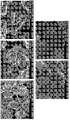
- Si wafer 2 is a SEM photograph taken after drying the conductive material dispersion of Preparation Examples 1 to 5 (Preparation Examples 1 to 5 correspond to A to E in FIG. 2 in order) on a silicon wafer.
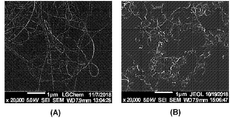
- FIG. 3 is a SEM photograph taken after drying the conductive material dispersion of Preparation Example 1 (A of FIG. 3) and Preparation Example 6 (B of FIG. 3) on a silicon wafer.
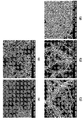
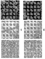
- Preparation Examples 1 to 5 correspond to each of A to E in FIG. 4 in order) for 2 weeks.
- Example 5 is a TEM photograph of each of the conductive material dispersions used in Example 1 and Comparative Example 4, and SEM photographs of the anodes of Example 1 (FIG. 5A) and Comparative Example 4 (FIG. 5B).
- the "specific surface area” is measured by the BET method, and specifically, may be calculated from the amount of nitrogen gas adsorption under liquid nitrogen temperature (77K) using BELSORP-mini II of BEL Japan.
- the electrode according to the present invention includes an electrode active material layer, and the electrode active material layer includes an electrode active material; Hydrogenated nitrile butadiene rubber; And a conductive material; wherein the conductive material includes a carbon nanotube structure in which 2 to 5,000 single-walled carbon nanotube units are bonded, wherein the carbon nanotube structure is 0.01% to 0.5% by weight in the electrode active material layer It can be included in %.
- the electrode may include an electrode active material layer.
- the electrode may further include a current collector, in which case the electrode active material layer may be disposed on one or both surfaces of the current collector.
- the current collector is not particularly limited as long as it is a conductive material without causing chemical changes to the battery, for example, copper, stainless steel, aluminum, nickel, titanium, alloys thereof, carbon, nickel, titanium on the surface thereof. , Surface-treated with silver or the like or calcined carbon may be used.
- the current collector may generally have a thickness of 3 ⁇ m to 500 ⁇ m, and fine unevenness may be formed on the surface of the current collector to enhance the bonding strength of the negative electrode active material.
- the electrode current collector may be used in various forms, such as a film, a sheet, a foil, a net, a porous material, a foam, and a nonwoven fabric.
- the electrode active material layer may include an electrode active material; Hydrogenated nitrile butadiene rubber; And a conductive material.
- the electrode active material may be a positive electrode active material or negative electrode active materials generally used in the art, and the kind is not particularly limited.
- lithium oxide including lithium and at least one metal such as cobalt, manganese, nickel, or aluminum
- the lithium oxide is a lithium-manganese-based oxide (eg, LiMnO 2 , LiMn 2 O, etc.), a lithium-cobalt-based oxide (eg, LiCoO 2, etc.), and a lithium-nickel-based oxide (eg For example, LiNiO 2 ), lithium-nickel-manganese oxide (e.g., LiNi 1-Y1 Mn Y1 O 2 (here, 0 ⁇ Y1 ⁇ 1), LiNi Z1 Mn 2-Z1 O 4 (here, 0 ⁇ Z1 ⁇ 2), lithium-nickel-cobalt oxide (e.g., LiNi 1-Y2 Co Y2 O 2 (here, 0 ⁇ Y2 ⁇ 1), etc.), lithium-manganese-cobalt oxide ( For example, LiCo 1-Y3 Mn Y3 O
- examples of the negative electrode active material include carbonaceous materials such as artificial graphite, natural graphite, graphitized carbon fiber, and amorphous carbon; Metal compounds capable of alloying with lithium such as Si, Al, Sn, Pb, Zn, Bi, In, Mg, Ga, Cd, Si alloy, Sn alloy, or Al alloy; Metal oxides capable of doping and undoping lithium such as SiO v (0 ⁇ v ⁇ 2), SnO 2 , vanadium oxide, and lithium vanadium oxide; Or a composite including the metal compound and a carbonaceous material, such as a Si-C composite or a Sn-C composite, and any one or a mixture of two or more of them may be used.
- a metal lithium thin film may be used as the negative electrode active material.
- the carbon material both low crystalline carbon and high crystalline carbon may be used.
- the electrode active material may be included in an amount of 70 wt% to 99.5 wt%, preferably 80 wt% to 99 wt%, based on the total weight of the electrode active material layer.
- excellent energy density, electrode adhesion, and electrical conductivity may be implemented.
- the conductive material may include a carbon nanotube structure.
- the carbon nanotube structure may include a plurality of single-walled carbon nanotube units.
- the carbon nanotube structure may be a carbon nanotube structure in which 2 to 5,000 single-walled carbon nanotube units are bonded to each other, and more specifically, the carbon nanotube structure is 2 to 4,500 single-walled carbon nanotubes. It may be a carbon nanotube structure in which tube units are bonded to each other. More specifically, in consideration of the dispersibility of the carbon nanotube structure and durability of the electrode, the carbon nanotube structure is most preferably a carbon nanotube structure in which 2 to 50 single-walled carbon nanotube units are bonded to each other. .
- the single-walled carbon nanotube units are arranged side by side (the long axes of the units are bonded in parallel to each other to have a flexible cylindrical structure) to form the carbon nanotube structure, and thus carbon
- the nanotube structure may have a rope shape.
- the carbon nanotube structures in the electrode may be connected to each other to exhibit a network structure.
- Conventional electrodes including carbon nanotubes are generally bundled or entangled type carbon nanotubes (single-walled carbon nanotube units or multi-walled carbon nanotube units attached to each other or entangled) ) Is dispersed in a dispersion medium to prepare a conductive material dispersion, and then prepared by using the conductive material dispersion. At this time, the carbon nanotubes are completely dispersed in the conventional conductive material dispersion, and exist as a conductive material dispersion in which single-stranded carbon nanotube units are dispersed. In the conventional conductive material dispersion, the carbon nanotube units are easily cut through an excessive dispersion process, so that the carbon nanotube units have a shorter length compared to the initial stage.
- the carbon nanotube units can be easily cut during the electrode rolling process.
- the problem of cutting the carbon nanotube units according to the volume change of the electrode active material additionally occurs. Accordingly, there is a problem in that the conductivity of the electrode is reduced accordingly, and the input characteristics, output characteristics, and life characteristics of the battery are deteriorated.
- the structure is high due to the mechanism of node growth (not smooth linear, but due to defects occurring in the growth process). Therefore, in the dispersion process, the multi-walled carbon nanotube units are more easily cut, and the multi-walled carbon nanotube units cut short by ⁇ - ⁇ stacking by carbon of the unit are likely to be aggregated with each other. Accordingly, it is difficult to more evenly disperse and exist in the electrode slurry.
- the average diameter of the single-walled carbon nanotube unit may be 0.5nm to 10nm, specifically 1nm to 9nm. When the average diameter is satisfied, there is an effect of maximizing the conductivity in the electrode even with a very small amount of the conductive material.
- the average diameter corresponds to the average value of the upper 100 single-walled carbon nanotubes and the lower 100 single-walled carbon nanotubes having a large average diameter when the prepared electrode is observed through SEM.
- the average length of the single-walled carbon nanotube unit may be 1 ⁇ m to 100 ⁇ m, and specifically 5 ⁇ m to 50 ⁇ m.
- the average length corresponds to the average value of the upper 100 single-walled carbon nanotubes and the lower 100 single-walled carbon nanotubes having a large average length when the prepared electrode is observed through SEM.
- the specific surface area of the single-walled carbon nanotube unit may be 500m 2 /g to 1,000m 2 /g, and specifically 600m 2 /g to 800m 2 /g. When the above range is satisfied, a conductive path in the electrode can be smoothly secured by a large specific surface area, and thus, there is an effect of maximizing the conductivity in the electrode even with a very small amount of the conductive material.
- the specific surface area of the single-walled carbon nanotube unit may be specifically calculated from the nitrogen gas adsorption amount under liquid nitrogen temperature (77K) using BELSORP-mini II of BEL Japan.
- the carbon nanotube structure may be included in an amount of 0.01% to 0.5% by weight in the electrode active material layer, specifically 0.03% to 0.3% by weight, and more specifically 0.05% to 0.2% by weight. .
- a conductive path of the electrode is secured, so that the life characteristics of the battery can be improved while maintaining a low level of electrode resistance.
- the electrode active material layer does not contain the carbon nanotube structure, or even if it is unintentionally included, it is negligible. It can be included in low content. In other words, when an electrode is manufactured through a conventional conductive material dispersion comprising a completely dispersed single-walled carbon nanotube unit, the above-described carbon nanotube structure content cannot be derived.
- the electrode in order to compensate for the low conductivity of the multi-walled carbon nanotube unit, a high content (eg, more than 0.5% by weight) of the multi-walled carbon nanotube unit has to be used.
- a high content eg, more than 0.5% by weight
- the single-walled carbon nanotube units are used in a low content due to the problem of cutting the single-walled carbon nanotube units.
- the carbon nanotube structure included in the electrode of the present invention has a form in which 2 to 5,000 single-walled carbon nanotube units are combined side by side with each other. Accordingly, even when the battery is driven, the length can be smoothly maintained without being cut, so that the conductivity of the electrode can be maintained, and the conductivity of the electrode can be smoothly secured based on the high conductivity of the single-walled carbon nanotube unit. Accordingly, even if the content of the carbon nanotube structure in the electrode is at a low level, the input characteristics, output characteristics, and life characteristics of the battery may be excellent.
- the hydrogenated nitrile butadiene rubber is a material that starts to be included in the electrode from the conductive material dispersion required for preparing the electrode slurry.
- the hydrogenated nitrile butadiene rubber serves to help smoothly disperse the bundled carbon nanotubes in the conductive material dispersion.
- the weight average molecular weight of the hydrogenated nitrile butadiene rubber may be 50,000 g/mol to 500,000 g/mol, and specifically 100,000 g/mol to 300,000 g/mol.
- the above range is satisfied, since the hydrogenated nitrile butadiene rubber can easily penetrate between single-walled carbon nanotube units in the bundled carbon nanotube, appropriate dispersion of the bundled carbon nanotube is possible, and the The phase stability of the conductive material dispersion may be improved.
- the hydrogenated nitrile butadiene rubber may be included in an amount of 0.1% to 5.0% by weight in the electrode active material layer, specifically 0.1% to 3.0% by weight, more specifically 0.1% to 3.0% by weight, for example, 0.3 It may be included in wt% to 3.0 wt%.
- the diameter of the carbon nanotube structure is appropriately controlled, the dispersion stability of the carbon nanotube structure in the electrode slurry is improved, and between the binder (especially PVdF) and the hydrogenated nitrile butadiene rubber Gelation due to compatibility can be prevented. Accordingly, input characteristics, output characteristics, and life characteristics of the battery may be improved.
- the weight ratio of the carbon nanotube structure and the hydrogenated nitrile butadiene rubber may be 1:0.1 to 1:10, and specifically 1:1 to 1:5.
- the diameter of the carbon nanotube structure is appropriately controlled, the dispersion stability of the carbon nanotube structure in the electrode slurry is further improved, and the binder (especially PVdF) and the hydrogenated nitrile butadiene rubber Gelation due to liver compatibility can be further prevented. Accordingly, input characteristics, output characteristics, and life characteristics of the battery may be improved.
- the electrode active material layer may further include a binder.
- the binder is for securing adhesion between electrode active materials or between the electrode active material and the current collector, and general binders used in the art may be used, and the type is not particularly limited.
- the binder for example, polyvinylidene fluoride (PVDF), vinylidene fluoride-hexafluoropropylene copolymer (PVDF-co-HFP), polyvinyl alcohol, polyacrylonitrile, carboxy Methylcellulose (CMC), starch, hydroxypropylcellulose, regenerated cellulose, polyvinylpyrrolidone, tetrafluoroethylene, polyethylene, polypropylene, ethylene-propylene-diene polymer (EPDM), sulfonated -EPDM, styrene butadiene rubber (SBR), fluorine rubber, or various copolymers thereof may be mentioned, and one of them alone or a mixture of two or more may be used
- the binder may be included in an amount of 10% by weight or less based on the total weight of the electrode active material layer, and preferably in an amount of 1% to 3% by weight. When the content of the binder satisfies the above range, it is possible to implement excellent electrode adhesion while minimizing an increase in electrode resistance.
- the electrode manufacturing method of the present invention comprises the steps of: (1) preparing a mixture comprising a bundled carbon nanotube, a hydrogenated nitrile butadiene rubber, and a dispersion medium; (2) dispersing the bundled carbon nanotubes in the mixture to form a conductive material dispersion; (3) preparing an electrode slurry including the conductive material dispersion and an electrode active material; And (4) applying the electrode slurry on a current collector and then drying it.
- the electrode of the above-described embodiment can be manufactured.
- the mixture may be prepared by adding bundled carbon nanotubes and hydrogenated nitrile butadiene rubber to a dispersion medium.
- the bundled carbon nanotubes exist in a bundle form by aggregation of the above-described single-walled carbon nanotube units, and generally include two or more single-walled carbon nanotube units. Specifically, the number of carbon nanotube units constituting the bundled carbon nanotubes is greater than the number of carbon nanotube units constituting the above-described carbon nanotube structure.
- the hydrogenated nitrile butadiene rubber is the same as the hydrogenated nitrile butadiene rubber of the above-described Examples, and thus description thereof will be omitted.
- the weight ratio of the bundled carbon nanotubes and the hydrogenated nitrile butadiene rubber may be 1:0.1 to 1:10, specifically 1:1 to 1:5.
- the diameter of the carbon nanotube structure is appropriately controlled, the dispersion stability of the carbon nanotube structure in the electrode slurry is further improved, and gelation due to compatibility between a binder (especially PVdF) and the hydrogenated nitrile butadiene rubber ) Can be further prevented. Accordingly, input characteristics, output characteristics, and life characteristics of the battery may be improved.
- dispersion medium examples include amide polar organic solvents such as dimethylformamide (DMF), diethyl formamide, dimethyl acetamide (DMAc), and N-methyl pyrrolidone (NMP); Methanol, ethanol, 1-propanol, 2-propanol (isopropyl alcohol), 1-butanol (n-butanol), 2-methyl-1-propanol (isobutanol), 2-butanol (sec-butanol), 1-methyl Alcohols such as -2-propanol (tert-butanol), pentanol, hexanol, heptanol or octanol; Glycols such as ethylene glycol, diethylene glycol, triethylene glycol, propylene glycol, 1,3-propanediol, 1,3-butanediol, 1,5-pentanediol, or hexylene glycol; Polyhydric alcohols such as glycerin
- the solid content in the mixture may be 0.1% by weight to 10% by weight, specifically 1% by weight to 5% by weight.
- the diameter of the carbon nanotube structure is appropriately controlled, and dispersion stability of the carbon nanotube structure in the electrode slurry may be further improved.
- the electrode slurry may have a high solid content while maintaining an appropriate viscosity and elasticity.
- the process of dispersing the bundled carbon nanotubes in the mixture is a homogenizer, a beads mill, a ball mill, a basket mill, an attraction mill, a universal stirrer, a clear mixer, a spike mill, a TK mixer, or an ultrasonic dispersing (sonification) equipment. It can be carried out using a mixing device such as. Among them, the beads mill method is preferred in that it can precisely control the diameter and size of the carbon nanotube structure, achieve a uniform distribution of the carbon nanotube structure, and have advantages in terms of cost. .
- the bead mill method may be as follows.
- the mixture may be placed in a container containing beads, and the bundled carbon nanotubes may be dispersed by rotating the container.
- the average particle diameter of the beads may be 0.5mm to 1.5mm, specifically 0.5mm to 1.0mm.
- the diameter and size of the carbon nanotube structure can be appropriately controlled without breaking during the dispersion process, and a dispersion solution having a uniform composition can be prepared.
- the rotational speed of the container may be 500RPM to 10,000RPM, specifically 2,000RPM to 6,000RPM.
- the diameter and size of the carbon nanotube structure can be appropriately controlled without breaking during the dispersion process, and a dispersion solution having a uniform composition can be prepared.
- the time during which the beads mill is performed may be 0.5 to 10 hours, specifically 1 to 5 hours, and more specifically 1 to 2 hours.
- the bead mill execution time refers to the total time to which the beads mill is applied, and thus, if several bead mill is performed, it means the total time over the several times.
- the bead mill conditions are for dispersing the bundled carbon nanotubes at an appropriate level, and specifically, except for the case where the bundled carbon nanotubes are completely dispersed into a single strand of single-walled carbon nanotubes. That is, in the beadmill condition, the bundled carbon nanotubes are dispersed at an appropriate level to form a carbon nanotube structure in which 2 to 5,000 single-walled carbon nanotube units are side by side in the prepared conductive material dispersion. It is to do. This can be achieved only when the composition of the mixture, bead mill conditions, and the like are strictly controlled.
- a conductive material dispersion including a carbon nanotube structure may be formed.
- an electrode active material is mixed with the conductive material dispersion to form an electrode slurry.
- the electrode active materials described above may be used as the electrode active material.
- the electrode slurry may further contain a binder and a solvent as necessary.
- the binder the binder of the above-described embodiment may be used.
- the solvent include amide polar organic solvents such as dimethylformamide (DMF), diethyl formamide, dimethyl acetamide (DMAc), and N-methyl pyrrolidone (NMP); Methanol, ethanol, 1-propanol, 2-propanol (isopropyl alcohol), 1-butanol (n-butanol), 2-methyl-1-propanol (isobutanol), 2-butanol (sec-butanol), 1-methyl Alcohols such as -2-propanol (tert-butanol), pentanol, hexanol, heptanol or octanol; Glycols such as ethylene glycol, diethylene glycol, triethylene glycol, propylene glycol, 1,3-propanediol, 1,
- the electrode active material may be included in an amount of 70% to 99.5% by weight, preferably 80% to 99% by weight, based on the total solid content in the electrode slurry.
- the content of the electrode active material satisfies the above range, excellent energy density, electrode adhesion, and electrical conductivity may be implemented.
- the binder when a binder is included, the binder may be included in an amount of 10 wt% or less, specifically 0.5 wt% to 5 wt%, preferably 1 wt% to 3 wt%, based on the total solid content in the electrode slurry.
- the solid content in the electrode slurry may be 60% to 80% by weight, and specifically 65% to 75% by weight.
- the above range is satisfied, when drying after applying the electrode slurry, migration of the conductive material and the binder due to evaporation of the solvent may be suppressed, and an electrode having excellent electrode adhesion and electrical conductivity may be manufactured. Furthermore, a high-quality electrode with less deformation of the electrode during rolling can be manufactured.
- the electrode slurry prepared as described above is applied and dried to form an electrode active material layer.
- the electrode active material layer is a method of drying after applying the electrode slurry on the electrode current collector, or applying the electrode slurry on a separate support, and then peeling the resulting film from the support on the electrode current collector. It can be formed through lamination. If necessary, after the electrode active material layer is formed through the above method, a process of rolling may be additionally performed.
- drying and rolling may be performed under appropriate conditions in consideration of the physical properties of the electrode to be finally manufactured, and is not particularly limited.
- the secondary battery according to the present invention includes the electrode of the present invention described above.
- the electrode may be at least one of an anode and a cathode.
- the secondary battery according to the present invention may include a positive electrode, a negative electrode, a separator disposed between the positive electrode and the negative electrode, and an electrolyte.
- At this time, at least one of the positive electrode and the negative electrode includes the electrode of the present invention, that is, an electrode active material layer, and the electrode active material layer includes: an electrode active material; Hydrogenated nitrile butadiene rubber; And a conductive material, wherein the conductive material includes a carbon nanotube structure in which 2 to 5,000 single-walled carbon nanotube units are bonded, wherein the carbon nanotube structure is 0.01% to 0.5% by weight in the electrode active material layer It may be an electrode included as.
- the electrode of the present invention may be an anode. Since the electrode according to the present invention has been described above, a detailed description will be omitted, and only the remaining components will be described below.
- the separator separates the negative electrode and the positive electrode and provides a passage for lithium ions to move, and may be used without particular limitation as long as it is generally used as a separator in a secondary battery.
- the separator is a porous polymer film, for example, a porous polymer made of polyolefin-based polymers such as ethylene homopolymer, propylene homopolymer, ethylene/butene copolymer, ethylene/hexene copolymer, and ethylene/methacrylate copolymer.
- a polymer film or a laminate structure of two or more layers thereof may be used.
- a conventional porous nonwoven fabric for example, a nonwoven fabric made of a high melting point glass fiber, polyethylene terephthalate fiber, or the like may be used.
- a coated separator containing a ceramic component or a polymer material may be used to secure heat resistance or mechanical strength, and may be optionally used in a single layer or multilayer structure.
- electrolyte examples include, but are not limited to, an organic liquid electrolyte, an inorganic liquid electrolyte, a solid polymer electrolyte, a gel polymer electrolyte, a solid inorganic electrolyte, and a molten inorganic electrolyte that can be used when manufacturing a lithium secondary battery.
- the electrolyte may include a non-aqueous organic solvent and a metal salt.
- non-aqueous organic solvent for example, N-methyl-2-pyrrolidinone, propylene carbonate, ethylene carbonate, butylene carbonate, dimethyl carbonate, diethyl carbonate, gamma-butyllolactone, 1,2-dime Oxyethane, tetrahydroxy franc (franc), 2-methyl tetrahydrofuran, dimethyl sulfoxide, 1,3-dioxolone, formamide, dimethylformamide, dioxolone, acetonitrile, nitromethane, methyl formate, Methyl acetate, phosphoric acid tryester, trimethoxy methane, dioxolone derivative, sulfolane, methyl sulfolane, 1,3-dimethyl-2-imidazolidinone, propylene carbonate derivative, tetrahydrofuran derivative, ether, pyrofion
- An aprotic organic solvent such as methyl acid or ethy
- ethylene carbonate and propylene carbonate which are cyclic carbonates
- cyclic carbonates are highly viscous organic solvents and can be preferably used because they dissociate lithium salts well because of their high dielectric constant.
- These cyclic carbonates include dimethyl carbonate and diethyl carbonate. If the same low viscosity, low dielectric constant linear carbonate is mixed and used in an appropriate ratio, an electrolyte having a high electrical conductivity can be made, and thus it can be more preferably used.
- the metal salt may be a lithium salt
- the lithium salt is a material that is readily soluble in the non-aqueous electrolyte, for example, is in the lithium salt anion F -, Cl -, I - , NO 3 -, N (CN ) 2 -, BF 4 -, ClO 4 -, PF 6 -, (CF 3) 2 PF 4 -, (CF 3) 3 PF 3 -, (CF 3) 4 PF 2 -, (CF 3) 5 PF - , (CF 3) 6 P - , CF 3 SO 3 -, CF 3 CF 2 SO 3 -, (CF 3 SO 2) 2 N -, (FSO 2) 2 N -, CF 3 CF 2 (CF 3) 2 CO -, (CF 3 SO 2 ) 2 CH -, (SF 5) 3 C -, (CF 3 SO 2) 3 C -, CF 3 (CF 2) 7 SO 3 -, CF 3 CO 2 -, CH 3 CO 2 -
- the electrolyte includes, for example, haloalkylene carbonate-based compounds such as difluoroethylene carbonate, pyridine, and trivalent for the purpose of improving battery life characteristics, suppressing reduction in battery capacity, and improving battery discharge capacity.
- haloalkylene carbonate-based compounds such as difluoroethylene carbonate, pyridine, and trivalent for the purpose of improving battery life characteristics, suppressing reduction in battery capacity, and improving battery discharge capacity.
- Ethyl phosphite triethanolamine, cyclic ether, ethylene diamine, n-glyme, hexaphosphate triamide, nitrobenzene derivative, sulfur, quinone imine dye, N-substituted oxazolidinone, N,N-substituted imida
- additives such as zolidine, ethylene glycol dialkyl ether, ammonium salt, pyrrole, 2-methoxy ethanol, or aluminum trichloride, may be further included.
- the secondary battery according to the present invention as described above has excellent electrode adhesion compared to the conventional secondary battery, and has excellent lifespan characteristics at high temperatures.
- Bundled carbon nanotubes (specific surface area 650m 2 /g) and hydrogenated nitrile butadiene rubber (weight average molecular weight: 260,000 g/mol) consisting of single-walled carbon nanotube units with an average diameter of 1.5 nm and an average length of 5 ⁇ m or more It was mixed with N-methylpyrrolidone (NMP) as a solvent to prepare a mixture so that the solid content was 2.4% by weight.
- NMP N-methylpyrrolidone
- the mixture was stirred in a bead-mill method to disperse the bundled carbon nanotubes in a solvent to prepare a conductive material dispersion.
- the particle diameter of the beads was 1 mm
- the rotation speed of the stirring vessel containing the beads was Was 3,000 RPM, and the stirring was carried out for 60 minutes
- the conductive material dispersion contained a carbon nanotube structure in which 2 to 5,000 single-walled carbon nanotube units were bonded side by side.
- the carbon nanotube structure was 0.4% by weight, and the hydrogenated butadiene rubber was 2.0% by weight.
- a conductive material dispersion was prepared in the same manner as in Preparation Example 1, except that 0.4% by weight of the carbon nanotube structure and 0.2% by weight of hydrogenated nitrile butadiene rubber were present in the conductive material dispersion.
- a conductive material dispersion was prepared in the same manner as in Preparation Example 1, except that polyvinylidene fluorine (PVdF, Solef-5130) having a weight average molecular weight of 880,000 g/mol was used instead of the hydrogenated nitrile butadiene rubber.
- PVdF polyvinylidene fluorine
- a conductive material dispersion was prepared in the same manner as in Preparation Example 1, except that polyvinylidene fluorine (PVdF, KF9700) having a weight average molecular weight of 880,000 g/mol was used instead of the hydrogenated nitrile butadiene rubber.
- PVdF, KF9700 polyvinylidene fluorine having a weight average molecular weight of 880,000 g/mol
- a conductive material dispersion was prepared in the same manner as in Preparation Example 1, except that the hydrogenated nitrile butadiene rubber was not used.
- a conductive material dispersion was prepared in the same manner as in Preparation Example 1.
- FIGS. 2 and 3 For each of Preparation Examples 1 to 6, whether carbon nanotube structures were formed and dispersibility were observed through SEM, and are shown in FIGS. 2 and 3.
- a to E in Fig. 2 respectively correspond to Preparation Examples 1 to 5 in sequence.
- 3A corresponds to Manufacturing Example 1
- FIG. 3B corresponds to Manufacturing Example 6.
- Fig. 4 shows the progress of leaving the conductive material dispersions of Preparation Examples 1 to 5 at 25°C for 2 weeks.
- NCM622 LiNi 0.6 Co 0.2 Mn 0.2 O 2
- PVDF a binder
- NMP N-methylpyrrolidone
- a positive electrode slurry of 72.0% by weight was prepared.
- the positive electrode slurry was coated on an Al thin film current collector having a thickness of 20 ⁇ m, dried at 130° C., and rolled to prepare a positive electrode including a positive electrode active material layer.
- the LiNi 0.6 Co 0.2 Mn 0.2 O 2 (NCM622) is 97.9% by weight, the binder is 1.8% by weight, the hydrogenated nitrile butadiene rubber is 0.25% by weight, the carbon nanotube structure is included in 0.05% by weight do.
- a rope-shaped carbon nanotube structure forms a network structure and connects NCM622 to each other.
- NCM622 LiNi 0.6 Co 0.2 Mn 0.2 O 2
- PVDF a binder
- NMP N-methylpyrrolidone
- a positive electrode slurry of 70.1% by weight was prepared.
- the positive electrode slurry was coated on an Al thin film current collector having a thickness of 20 ⁇ m, dried at 130° C., and rolled to prepare a positive electrode including a positive electrode active material layer.
- the LiNi 0.6 Co 0.2 Mn 0.2 O 2 (NCM622) is 97.6% by weight, the binder is 1.8% by weight, the hydrogenated nitrile butadiene rubber is 0.5% by weight, and the carbon nanotube structure is included in 0.1% by weight. do.
- Carbon black with a specific surface area of 240 m 2 /g and hydrogenated nitrile butadiene rubber (weight average molecular weight: 260,000 g/mol) were mixed with N-methylpyrrolidone (NMP) as a solvent, and the solid content was 16.5% by weight A mixture was prepared so as to be.
- NMP N-methylpyrrolidone
- the mixture was stirred in a beads-mill method to disperse the bundled carbon nanotubes in a solvent to prepare a conductive material dispersion.
- the particle diameter of the beads was 1 mm
- the rotation speed of the stirring vessel containing the beads was 3,000 RPM
- the stirring was performed for 60 minutes.
- the carbon black was 15% by weight and the hydrogenated butadiene rubber was 1.5% by weight.
- LiNi 0.6 Co 0.2 Mn 0.2 O 2 (NCM622), a binder (PVDF, KF9700) was added to the conductive material dispersion, and N-methylpyrrolidone (NMP, N-methylpyrrolidone) was additionally added, resulting in a solid content of 72.0 weight.
- % Positive electrode slurry was prepared. The positive electrode slurry was coated on an Al thin film current collector having a thickness of 20 ⁇ m, dried at 130° C., and rolled to prepare a positive electrode including a positive electrode active material layer.
- the LiNi 0.6 Co 0.2 Mn 0.2 O 2 (NCM622) is 96.35% by weight, the binder is 2.0% by weight, the hydrogenated nitrile butadiene rubber is 0.15% by weight, and the carbon black is included in 1.5% by weight.
- NCM622 LiNi 0.6 Co 0.2 Mn 0.2 O 2
- NMP N-methylpyrrolidone
- a positive electrode slurry of 72.1% by weight was prepared.
- the positive electrode slurry was coated on an Al thin film current collector having a thickness of 20 ⁇ m, dried at 130° C., and rolled to prepare a positive electrode including a positive electrode active material layer.
- the LiNi 0.6 Co 0.2 Mn 0.2 O 2 (NCM622) is 97.48% by weight, the binder is 1.8% by weight, the hydrogenated nitrile butadiene rubber is 0.12% by weight, the multi-walled carbon nanotube unit is 0.6% by weight Included as.
- NCM622 LiNi 0.6 Co 0.2 Mn 0.2 O 2
- NMP N-methylpyrrolidone
- a positive electrode slurry of 71.8% by weight was prepared.
- the positive electrode slurry was coated on an Al thin film current collector having a thickness of 20 ⁇ m, dried at 130° C., and rolled to prepare a positive electrode including a positive electrode active material layer.
- the LiNi 0.6 Co 0.2 Mn 0.2 O 2 (NCM622) is 97.04% by weight, the binder is 2.0% by weight, the hydrogenated nitrile butadiene rubber is 0.16% by weight, the multi-walled carbon nanotube unit is 0.8% by weight Included as.
- Bundled carbon nanotubes (specific surface area 650m 2 /g) and hydrogenated nitrile butadiene rubber (weight average molecular weight: 260,000 g/mol) consisting of single-walled carbon nanotube units with an average diameter of 1.5 nm and an average length of 5 ⁇ m or more
- NMP hydrogenated nitrile butadiene rubber
- the mixture was stirred in a bead-mill method to disperse the bundled carbon nanotubes in a solvent to prepare a conductive material dispersion.
- the particle diameter of the beads was 1 mm
- the rotation speed of the stirring vessel containing the beads was Was 3,000 RPM, and performing the stirring for 60 minutes as 1 cycle, a total of 4 cycles (natural cooling performed for 60 minutes between cycles) was performed.
- the bundled carbon nanotubes were 0.4% by weight and the hydrogenated butadiene rubber was 4.0% by weight.
- LiNi 0.6 Co 0.2 Mn 0.2 O 2 (NCM622) and a binder (PVDF, KF9700) were added to the conductive material dispersion, and N-methylpyrrolidone (NMP, N-methylpyrrolidone) was additionally added, resulting in a solid content of 72.0 weight.
- % Positive electrode slurry was prepared. The positive electrode slurry was coated on an Al thin film current collector having a thickness of 20 ⁇ m, dried at 130° C., and rolled to prepare a positive electrode including a positive electrode active material layer.
- the LiNi 0.6 Co 0.2 Mn 0.2 O 2 (NCM622) is 97.65% by weight, the binder is 1.8% by weight, the hydrogenated nitrile butadiene rubber is 0.5% by weight, the single-walled carbon nanotube unit is 0.05% by weight Included as.
- FIG. 5B no carbon nanotube structure was observed in the positive electrode active material layer, and it can be seen that single-walled carbon nanotube units exist individually one by one. Even if the single-walled carbon nanotube units are partially overlapped and observed in FIG. 5B, this is not a bonded state, but only observed by overlapping the single-walled carbon nanotube units above and below the observation direction, and the orientation is not the same. not.
- the positive electrode slurries used for preparing the positive electrodes of Examples 1 and 2 and Comparative Examples 1 to 4 were vacuum-dried at a temperature of 130° C. for 3 hours, and then pulverized to prepare a powder. Thereafter, using the Loresta GP equipment of Mitsubishi Chem Analytic, the pellets were prepared under a load of 9.8 MPa in an atmosphere of 25° C. and 50% relative humidity. After that, the powder resistance was measured by the 4-probe method. The measurement results are shown in Table 1 below.
- a double-sided tape is attached to the slide glass, and the electrode punched at 20 mm ⁇ 180 mm is placed on it, and the electrode is reciprocated 10 times with a 2 kg roller, and then pulled at 200 mm/min using a UTM (TA company) device. The peeling force was measured. At this time, the measuring angle of the slide glass and the electrode was 90°.
- Table 1 The measurement results are shown in Table 1 below.
- a monocell was prepared by combining the positive electrode, the negative electrode, and a 15 ⁇ m-thick polyethylene-based separator prepared according to Examples 1 and 2 and Comparative Examples 1 to 4.
- the negative electrode was prepared by mixing graphite, SBR/CMC, and a conductive material in a weight ratio of 96.5: 2.5: 1 to prepare a negative electrode slurry, which was coated on 10 ⁇ m copper foil and dried at 100° C.
- Example 1 Example 2 Comparative Example 1 Comparative Example 2 Comparative Example 3 Comparative Example 4 Conductive material specific surface area (m 2 /g) 650 650 240 185 185 650 Conductive material content (% by weight) 0.1 (carbon nanotube structure) 0.05 (carbon nanotube structure) 1.5 (carbon black) 0.6 (multi-walled carbon nanotube monomer) 0.8 (multi-walled carbon nanotube monomer) 0.05 (fully dispersed carbon nanotube monomer) Binder content (% by weight) 1.8 1.8 2.0 1.8 2.0 1.8 Slurry solid content (% by weight) 72 73.3 72.0 72.1 72.0 73.3 Slurry powder resistance ( ⁇ cm) 21.8 22.7 154 72.7 29.6 1,580 Electrode adhesion (gf/20mm) 20.6 20.9 19.7 14.1 19.0 3.1 Life characteristics (%) 98.7 98.1 93.8 94.5 95.4 85.5
- Comparative Example 4 the bundled carbon nanotubes were excessively dispersed, so that the single-walled carbon nanotubes were separated one by one to exist in the electrode.
- the single-walled carbon nanotubes are cut during the battery manufacturing process, and like a rope-type carbon nanotube structure, a network structure cannot be formed, and only exists in close contact with the surface of the electrode active material. Accordingly, since the conductive network cannot be maintained smoothly, it can be seen that the slurry powder resistance is high, and the electrode adhesion and lifetime characteristics are low.
Landscapes
- Chemical & Material Sciences (AREA)
- Chemical Kinetics & Catalysis (AREA)
- Electrochemistry (AREA)
- General Chemical & Material Sciences (AREA)
- Engineering & Computer Science (AREA)
- Materials Engineering (AREA)
- Nanotechnology (AREA)
- Organic Chemistry (AREA)
- Manufacturing & Machinery (AREA)
- Inorganic Chemistry (AREA)
- Battery Electrode And Active Subsutance (AREA)
Priority Applications (6)
| Application Number | Priority Date | Filing Date | Title |
|---|---|---|---|
| EP20779769.7A EP3926710B1 (en) | 2019-03-28 | 2020-03-27 | Electrode and secondary battery including same |
| CN202411311882.3A CN119208510A (zh) | 2019-03-28 | 2020-03-27 | 电极和包括所述电极的二次电池 |
| ES20779769T ES2980606T3 (es) | 2019-03-28 | 2020-03-27 | Electrodo y batería secundaria que incluye el mismo |
| PL20779769.7T PL3926710T3 (pl) | 2019-03-28 | 2020-03-27 | Elektroda i zawierająca ją bateria wielokrotnego ładowania |
| US17/442,876 US20220158194A1 (en) | 2019-03-28 | 2020-03-27 | Electrode And Secondary Battery Including Same |
| CN202080026696.9A CN113661586B (zh) | 2019-03-28 | 2020-03-27 | 电极和包括所述电极的二次电池 |
Applications Claiming Priority (2)
| Application Number | Priority Date | Filing Date | Title |
|---|---|---|---|
| KR20190035776 | 2019-03-28 | ||
| KR10-2019-0035776 | 2019-03-28 |
Publications (1)
| Publication Number | Publication Date |
|---|---|
| WO2020197344A1 true WO2020197344A1 (ko) | 2020-10-01 |
Family
ID=72608844
Family Applications (1)
| Application Number | Title | Priority Date | Filing Date |
|---|---|---|---|
| PCT/KR2020/004272 Ceased WO2020197344A1 (ko) | 2019-03-28 | 2020-03-27 | 전극 및 이를 포함하는 이차 전지 |
Country Status (8)
| Country | Link |
|---|---|
| US (1) | US20220158194A1 (pl) |
| EP (1) | EP3926710B1 (pl) |
| KR (3) | KR102555206B1 (pl) |
| CN (2) | CN119208510A (pl) |
| ES (1) | ES2980606T3 (pl) |
| HU (1) | HUE067162T2 (pl) |
| PL (1) | PL3926710T3 (pl) |
| WO (1) | WO2020197344A1 (pl) |
Cited By (2)
| Publication number | Priority date | Publication date | Assignee | Title |
|---|---|---|---|---|
| CN115136346A (zh) * | 2020-10-23 | 2022-09-30 | 株式会社Lg新能源 | 负极和包括该负极的二次电池 |
| CN116368639A (zh) * | 2020-12-24 | 2023-06-30 | 株式会社Lg新能源 | 锂二次电池用正极和包含其的锂二次电池 |
Families Citing this family (6)
| Publication number | Priority date | Publication date | Assignee | Title |
|---|---|---|---|---|
| JP6941637B2 (ja) * | 2019-04-22 | 2021-09-29 | 第一工業製薬株式会社 | 電極用結着剤組成物、電極用塗料組成物、蓄電デバイス用電極、および蓄電デバイス |
| EP4181229B1 (en) * | 2021-03-12 | 2026-03-04 | LG Energy Solution, Ltd. | Electrode and method for manufacturing the same |
| CN117174905A (zh) * | 2023-09-01 | 2023-12-05 | 东阳利维能新能源科技有限公司 | 一种高电导性高容量正极极片、锂电池及其制备方法 |
| KR102894212B1 (ko) * | 2023-11-17 | 2025-12-03 | 주식회사 엘지에너지솔루션 | 전극, 리튬 이차 전지 및 전극의 제조 방법 |
| CN117317233B (zh) * | 2023-11-28 | 2024-04-02 | 天鹏锂能技术(淮安)有限公司 | 一种正极浆料及制备方法和应用 |
| CN117410494B (zh) * | 2023-12-15 | 2024-03-15 | 溧阳中科海钠科技有限责任公司 | 一种正极极片及其制备方法、钠离子电池和用电设备 |
Citations (5)
| Publication number | Priority date | Publication date | Assignee | Title |
|---|---|---|---|---|
| KR20170030438A (ko) * | 2015-09-09 | 2017-03-17 | 주식회사 엘지화학 | 탄소 나노튜브 분산액 및 이의 제조방법 |
| KR20170049459A (ko) * | 2015-10-28 | 2017-05-10 | 주식회사 엘지화학 | 도전재 분산액 및 이를 이용하여 제조한 리튬 이차전지 |
| KR20170069153A (ko) * | 2015-12-10 | 2017-06-20 | 주식회사 엘지화학 | 이차전지용 양극 및 이를 포함하는 이차전지 |
| KR20170069141A (ko) * | 2015-12-10 | 2017-06-20 | 주식회사 엘지화학 | 도전재 분산액 및 이를 이용하여 제조한 리튬 이차전지 |
| KR20170113250A (ko) * | 2016-03-24 | 2017-10-12 | 주식회사 엘지화학 | 도전재 분산액 및 이를 이용하여 제조한 이차전지 |
Family Cites Families (7)
| Publication number | Priority date | Publication date | Assignee | Title |
|---|---|---|---|---|
| US6183714B1 (en) * | 1995-09-08 | 2001-02-06 | Rice University | Method of making ropes of single-wall carbon nanotubes |
| EP1787955A4 (en) * | 2004-07-27 | 2010-06-23 | Nat Inst Of Advanced Ind Scien | A SINGLE-LAYER CARBONNANE TUBE AND ARRANGED CARBONNANORA TUBE COLLAR STRUCTURE, AND METHOD OF MANUFACTURING THEREOF, MANUFACTURING DEVICE THEREFOR AND USE THEREOF |
| EP3355392B1 (en) * | 2015-09-25 | 2019-11-13 | LG Chem, Ltd. | Carbon nanotube dispersion liquid and manufacturing method thereof |
| JP6809474B2 (ja) * | 2015-09-30 | 2021-01-06 | 日本ゼオン株式会社 | 二次電池電極用導電材ペースト組成物、二次電池電極用スラリー組成物、二次電池電極用アンダーコート層付き集電体、二次電池用電極、および二次電池 |
| WO2017099481A1 (ko) * | 2015-12-10 | 2017-06-15 | 주식회사 엘지화학 | 이차전지용 양극 및 이를 포함하는 이차전지 |
| JP7286799B2 (ja) * | 2019-10-04 | 2023-06-05 | エルジー エナジー ソリューション リミテッド | 電極およびそれを含む二次電池 |
| US12266800B2 (en) * | 2019-10-04 | 2025-04-01 | Lg Energy Solution, Ltd. | Electrode and secondary battery including the same |
-
2020
- 2020-03-27 EP EP20779769.7A patent/EP3926710B1/en active Active
- 2020-03-27 US US17/442,876 patent/US20220158194A1/en active Pending
- 2020-03-27 CN CN202411311882.3A patent/CN119208510A/zh active Pending
- 2020-03-27 PL PL20779769.7T patent/PL3926710T3/pl unknown
- 2020-03-27 ES ES20779769T patent/ES2980606T3/es active Active
- 2020-03-27 KR KR1020200037750A patent/KR102555206B1/ko active Active
- 2020-03-27 HU HUE20779769A patent/HUE067162T2/hu unknown
- 2020-03-27 WO PCT/KR2020/004272 patent/WO2020197344A1/ko not_active Ceased
- 2020-03-27 CN CN202080026696.9A patent/CN113661586B/zh active Active
-
2023
- 2023-07-06 KR KR1020230088035A patent/KR102788466B1/ko active Active
-
2025
- 2025-03-21 KR KR1020250036897A patent/KR20250044846A/ko active Pending
Patent Citations (5)
| Publication number | Priority date | Publication date | Assignee | Title |
|---|---|---|---|---|
| KR20170030438A (ko) * | 2015-09-09 | 2017-03-17 | 주식회사 엘지화학 | 탄소 나노튜브 분산액 및 이의 제조방법 |
| KR20170049459A (ko) * | 2015-10-28 | 2017-05-10 | 주식회사 엘지화학 | 도전재 분산액 및 이를 이용하여 제조한 리튬 이차전지 |
| KR20170069153A (ko) * | 2015-12-10 | 2017-06-20 | 주식회사 엘지화학 | 이차전지용 양극 및 이를 포함하는 이차전지 |
| KR20170069141A (ko) * | 2015-12-10 | 2017-06-20 | 주식회사 엘지화학 | 도전재 분산액 및 이를 이용하여 제조한 리튬 이차전지 |
| KR20170113250A (ko) * | 2016-03-24 | 2017-10-12 | 주식회사 엘지화학 | 도전재 분산액 및 이를 이용하여 제조한 이차전지 |
Cited By (2)
| Publication number | Priority date | Publication date | Assignee | Title |
|---|---|---|---|---|
| CN115136346A (zh) * | 2020-10-23 | 2022-09-30 | 株式会社Lg新能源 | 负极和包括该负极的二次电池 |
| CN116368639A (zh) * | 2020-12-24 | 2023-06-30 | 株式会社Lg新能源 | 锂二次电池用正极和包含其的锂二次电池 |
Also Published As
| Publication number | Publication date |
|---|---|
| KR20230107528A (ko) | 2023-07-17 |
| EP3926710A4 (en) | 2022-04-06 |
| KR20200115362A (ko) | 2020-10-07 |
| KR20250044846A (ko) | 2025-04-01 |
| CN113661586A (zh) | 2021-11-16 |
| PL3926710T3 (pl) | 2024-07-22 |
| HUE067162T2 (hu) | 2024-10-28 |
| US20220158194A1 (en) | 2022-05-19 |
| CN113661586B (zh) | 2024-10-22 |
| CN119208510A (zh) | 2024-12-27 |
| EP3926710A1 (en) | 2021-12-22 |
| KR102555206B1 (ko) | 2023-07-14 |
| ES2980606T3 (es) | 2024-10-02 |
| KR102788466B1 (ko) | 2025-04-01 |
| EP3926710B1 (en) | 2024-05-01 |
Similar Documents
| Publication | Publication Date | Title |
|---|---|---|
| WO2021066554A1 (ko) | 전극 및 이를 포함하는 이차 전지 | |
| WO2021034145A1 (ko) | 탄소나노튜브 분산액, 이를 포함하는 음극 슬러리, 음극 및 리튬 이차 전지 | |
| WO2021066560A1 (ko) | 양극 및 이를 포함하는 이차 전지 | |
| WO2021020939A1 (ko) | 음극, 상기 음극을 포함하는 이차 전지, 및 상기 음극의 제조 방법 | |
| WO2021029652A1 (ko) | 리튬 이차전지용 양극 및 이를 포함하는 리튬 이차전지 | |
| WO2021066495A1 (ko) | 전극 및 이를 포함하는 이차 전지 | |
| WO2019194662A1 (ko) | 전극, 상기 전극을 포함하는 이차 전지, 및 상기 전극의 제조 방법 | |
| WO2021025349A1 (ko) | 음극, 이의 제조방법 및 이를 포함하는 이차전지 | |
| WO2021215830A1 (ko) | 음극 및 이를 포함하는 이차 전지 | |
| WO2019117531A1 (ko) | 리튬 이차전지용 양극 활물질, 이의 제조방법, 이를 포함하는 리튬 이차전지용 양극 및 리튬 이차전지 | |
| WO2021101188A1 (ko) | 음극 및 이를 포함하는 이차전지 | |
| WO2021251663A1 (ko) | 음극 및 이를 포함하는 이차전지 | |
| WO2021066557A1 (ko) | 전극 및 이를 포함하는 이차 전지 | |
| WO2022086289A1 (ko) | 음극 및 이를 포함하는 이차 전지 | |
| WO2020040545A1 (ko) | 도전재 분산액, 이를 이용하여 제조된 전극 및 리튬 이차전지 | |
| WO2019103526A1 (ko) | 이차전지용 양극 슬러리 조성물, 이를 이용하여 제조된 이차전지용 양극 및 이차전지 | |
| WO2017171372A1 (ko) | 전극 활물질 슬러리 및 이를 포함하는 리튬 이차전지 | |
| WO2016200223A1 (ko) | 양극 합제 및 이를 포함하는 이차전지 | |
| KR20200115362A (ko) | 전극 및 이를 포함하는 이차 전지 | |
| WO2023120966A1 (ko) | 음극 조성물, 이를 포함하는 리튬 이차 전지용 음극 및 음극을 포함하는 리튬 이차 전지 | |
| WO2021066494A1 (ko) | 전극 및 이를 포함하는 이차 전지 | |
| WO2019147093A1 (ko) | 도전재, 이를 포함하는 전극 형성용 슬러리, 전극 및 이를 이용하여 제조되는 리튬 이차 전지 | |
| WO2023059152A1 (ko) | 양극 및 이를 포함하는 이차전지 | |
| WO2022231325A1 (ko) | 음극 및 상기 음극을 포함하는 이차 전지 | |
| WO2021066493A1 (ko) | 전극 및 이를 포함하는 이차 전지 |
Legal Events
| Date | Code | Title | Description |
|---|---|---|---|
| 121 | Ep: the epo has been informed by wipo that ep was designated in this application |
Ref document number: 20779769 Country of ref document: EP Kind code of ref document: A1 |
|
| NENP | Non-entry into the national phase |
Ref country code: DE |
|
| ENP | Entry into the national phase |
Ref document number: 2020779769 Country of ref document: EP Effective date: 20210917 |