WO2020200329A1 - Récipient d'additif amovible pour dispositif de lavage - Google Patents
Récipient d'additif amovible pour dispositif de lavage Download PDFInfo
- Publication number
- WO2020200329A1 WO2020200329A1 PCT/CN2020/091697 CN2020091697W WO2020200329A1 WO 2020200329 A1 WO2020200329 A1 WO 2020200329A1 CN 2020091697 W CN2020091697 W CN 2020091697W WO 2020200329 A1 WO2020200329 A1 WO 2020200329A1
- Authority
- WO
- WIPO (PCT)
- Prior art keywords
- container
- reservoir
- washing
- pump
- bottle
- Prior art date
- Legal status (The legal status is an assumption and is not a legal conclusion. Google has not performed a legal analysis and makes no representation as to the accuracy of the status listed.)
- Ceased
Links
Images



Classifications
-
- D—TEXTILES; PAPER
- D06—TREATMENT OF TEXTILES OR THE LIKE; LAUNDERING; FLEXIBLE MATERIALS NOT OTHERWISE PROVIDED FOR
- D06F—LAUNDERING, DRYING, IRONING, PRESSING OR FOLDING TEXTILE ARTICLES
- D06F39/00—Details of washing machines not specific to a single type of machines covered by groups D06F9/00 - D06F27/00
- D06F39/02—Devices for adding soap or other washing agents
- D06F39/022—Devices for adding soap or other washing agents in a liquid state
-
- D—TEXTILES; PAPER
- D06—TREATMENT OF TEXTILES OR THE LIKE; LAUNDERING; FLEXIBLE MATERIALS NOT OTHERWISE PROVIDED FOR
- D06F—LAUNDERING, DRYING, IRONING, PRESSING OR FOLDING TEXTILE ARTICLES
- D06F58/00—Domestic laundry dryers
- D06F58/20—General details of domestic laundry dryers
- D06F58/203—Laundry conditioning arrangements
-
- D—TEXTILES; PAPER
- D06—TREATMENT OF TEXTILES OR THE LIKE; LAUNDERING; FLEXIBLE MATERIALS NOT OTHERWISE PROVIDED FOR
- D06F—LAUNDERING, DRYING, IRONING, PRESSING OR FOLDING TEXTILE ARTICLES
- D06F21/00—Washing machines with receptacles, e.g. perforated, having a rotary movement, e.g. oscillatory movement
- D06F21/02—Washing machines with receptacles, e.g. perforated, having a rotary movement, e.g. oscillatory movement about a horizontal axis
- D06F21/04—Washing machines with receptacles, e.g. perforated, having a rotary movement, e.g. oscillatory movement about a horizontal axis within an enclosing receptacle
-
- D—TEXTILES; PAPER
- D06—TREATMENT OF TEXTILES OR THE LIKE; LAUNDERING; FLEXIBLE MATERIALS NOT OTHERWISE PROVIDED FOR
- D06F—LAUNDERING, DRYING, IRONING, PRESSING OR FOLDING TEXTILE ARTICLES
- D06F39/00—Details of washing machines not specific to a single type of machines covered by groups D06F9/00 - D06F27/00
- D06F39/12—Casings; Tubs
-
- D—TEXTILES; PAPER
- D06—TREATMENT OF TEXTILES OR THE LIKE; LAUNDERING; FLEXIBLE MATERIALS NOT OTHERWISE PROVIDED FOR
- D06F—LAUNDERING, DRYING, IRONING, PRESSING OR FOLDING TEXTILE ARTICLES
- D06F58/00—Domestic laundry dryers
- D06F58/02—Domestic laundry dryers having dryer drums rotating about a horizontal axis
- D06F58/04—Details
Definitions
- the subject matter generally relates to washing equipment, such as washing machine equipment and dryer equipment, and more specifically to washing equipment that utilizes a reservoir for supplying additives to the load within the washing equipment.
- Washing equipment such as washer equipment, dryer equipment, and washer/dryer combined equipment, usually includes a cabinet and a drum (sometimes called a basket, as in the case of washing machine equipment), the drum is rotatably installed in the cabinet It defines a chamber for receiving items for washing and/or drying.
- conventional equipment for drying items such as a clothes dryer (or washing dryer) for drying clothes items, usually includes a cabinet having a rotating drum for tumbling clothes and washing items therein.
- conventional washing machine equipment usually includes a rotatable washing basket or drum, which rotates in the washing tub during the operation of the equipment to agitate the items in the chamber, squeeze cleaning fluid from the items in the chamber, and so on.
- additives may be provided to reduce wrinkles, improve the smell of clothes, and/or other fabric treatment additives, such as fabric softeners, may be provided.
- the washing machine device may use various fluid additives (in addition to water) to assist in washing and rinsing the loaded items.
- cleaning agents and/or detergents can be added during the cleaning and pre-cleaning cycles of the washer equipment.
- the fabric softener may be added during the rinse cycle of the washing machine device.
- the user may prefer more scented clothes, or the laundry to be washed may have been left in the drum for a long time and may smell slightly stale or moldy.
- Conventional mechanisms for supplying additives include systems for automatically dispensing detergent and/or fabric softener or manually placing drying sheets or other additives in the drum before activation of the washing device. Alternatively, the clothes may be washed and dried again, resulting in excessive use of energy and water.
- washing device having improved features for storing additives and selectively providing additives to the drum would be advantageous.
- washing equipment that includes features for easy access to containers for additives, such as for filling, cleaning, and/or replacing the containers, would be useful.
- a washing device defines a vertical direction, a lateral direction, and a lateral direction.
- the vertical, lateral and lateral directions are perpendicular to each other.
- the washing device includes a cabinet that extends from the rear panel to the front panel in the lateral direction, from the left panel to the right panel in the lateral direction, and from the bottom panel to the top cover in the vertical direction.
- the cabinet defines the internal volume.
- the drum is rotatably installed in the internal volume of the cabinet.
- the drum defines a cavity for receiving clothes.
- the container is removably installed in the cabinet at the front panel of the cabinet.
- the container is configured to receive additives.
- the container is in fluid communication with the chamber to provide additives from the container to the chamber.
- an additive supply system for washing equipment includes a cabinet defining an internal volume and a drum rotatably installed in the internal volume of the cabinet.
- the drum defines a cavity for receiving clothes.
- the additive supply system includes a container that is configured to be removably installed in the cabinet at the front panel of the cabinet.
- the container is configured to receive additives.
- the container is configured to be in fluid communication with the chamber when the container is installed in the cabinet to provide additives from the container to the chamber.
- Figure 1 provides a perspective view of a dryer device according to one or more exemplary embodiments of the present disclosure.
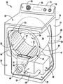
- Figure 2 provides a perspective view of the example dryer device of Figure 1 with parts of the cabinet of the dryer device removed to reveal certain components of the dryer device.
- Figure 3 provides an enlarged view of a portion of the front panel of the dryer device according to one or more exemplary embodiments of the present disclosure.
- Figure 4 provides a perspective view of a washing machine device according to one or more exemplary embodiments of the present subject matter.
- Figure 5 provides a side cross-sectional view of the exemplary washer apparatus of Figure 4.
- Figure 6 provides a perspective view of an additive supply system for use in washing equipment such as the dryer equipment of Figures 1-3 or the washing machine equipment of Figures 4-5 according to one or more exemplary embodiments of the present disclosure.
- Figure 7 provides an exploded view of certain components of the additive supply system of Figure 6.
- Figure 8 provides an exploded view of additional components of the additive supply system of Figure 6.
- Figure 9 provides a cross-sectional view of the additive supply system of Figure 6.
- Figure 10 provides a cross-sectional view of an additive supply system for washing such as the dryer device of Figures 1-3 or the washing machine device of Figures 4-5 according to one or more additional exemplary embodiments of the present disclosure equipment.
- approximate terms such as “approximately,” “substantially,” or “approximately,” include values greater than or less than ten percent of the stated value. When used in the context of an angle or direction, these terms are included within ten degrees greater or less than the angle or direction. For example, “substantially vertical” includes directions within ten degrees of vertical in any direction (for example, clockwise or counterclockwise).
- FIG. 1 provides a perspective view of a dryer device 10, which is an example of a washing device according to an exemplary embodiment of the present disclosure.
- FIG. 2 provides another perspective view of the dryer device 10 in which a portion of the cabinet or housing 12 of the dryer device 10 is removed in order to show certain components of the dryer device 10.
- the dryer device 10 generally defines a vertical direction V, a lateral direction L, and a lateral direction T, each of which is perpendicular to each other, so that an orthogonal coordinate system is defined.
- V vertical direction
- L a lateral direction L
- T a lateral direction
- the dryer device 10 is provided by way of example only.
- Other washing equipment with different appearance and different features can also be used with this theme.
- the additive supply system 200 described herein may be provided in a vertical axis dryer device, a washer device, a combined washer/dryer device, or other washing devices.
- the cabinet 12 includes a front panel 14, a rear panel 16, a left side panel 18 and a right side panel 20 spaced apart from each other by the front panel 14 and the rear panel 16, a bottom panel 22 and a top cover 24.
- terms such as “left” and “right” or “front” and “back” refer to the user facing the washing device (for example, the dryer device 10) to approach and/or operate the washing device Perspective.
- a user stands in front of the dryer device 10, such as at or near the front panel 14, to access the door 33 and/or the input 70 (the door 33 and the input 70 are described in more detail below).
- Inside the cabinet 12 an internal volume 29 is defined.
- the drum or container 26 is installed to rotate around a substantially horizontal axis within the internal volume 29.
- the drum 26 defines a cavity 25 for receiving laundry items for tumbling and/or drying.
- the drum 26 extends between the front part 37 and the back part 38.
- the drum 26 also includes a back or rear wall 34 at the back portion 38 of the drum 26, for example.
- the supply duct 41 may be installed to the rear wall 34 and receive heated air that has been heated by the heating assembly or system 40.
- a door 202 may be provided in the front panel 14 to provide selective access to the additive supply system 200 (e.g., Figure 3).
- the door 202 may be provided in or near the lower corner of the front panel 14.
- the door 202 is positioned in the lower right corner of the front panel 14.
- the term “clothing” or “clothing” includes but is not necessarily limited to fabrics, textiles, clothing, linen, paper, or other objects.
- the term “loading” or “washing load” refers to a combination of clothes that can be washed together in a washing machine device or dried together in a dryer device, and can include different or similar types or types in a particular washing process A mixture of different or similar items of fabrics, textiles, clothing and linen clothing.
- the motor 31 is provided to rotate the drum 26 about a horizontal axis, for example, via a pulley and a belt (not shown).
- the drum 26 is generally cylindrical in shape with an outer cylindrical wall 28 and a front flange or wall 30 that defines the opening 32 of the drum 26, for example at the front portion 37 of the drum 26, It is used to load items into and unload items from the chamber 25 of the drum 26.
- a plurality of lifting members or baffles 27 are provided in the cavity 25 of the drum 26 to lift the items therein, and then allow the items to roll back to the bottom of the drum 26 when the drum 26 rotates.
- the baffle 27 may be installed to the drum 26 so that the baffle 27 rotates with the drum 26 during the operation of the dryer device 10.
- the drum 26 includes a rear wall 34 which is rotatably supported within the main housing 12 by suitable fixed bearings.
- the rear wall 34 may be fixed or may be rotatable.
- the rear wall 34 may include, for example, a plurality of holes that receive hot air that has been heated by the heating system 40, which may include, for example, electrical resistance heating elements, gas burners, and/or heat pumps.
- the heated air carrying moisture is sucked from the drum 26 by an air handler (such as a blower fan 48) that generates negative air pressure in the drum.
- the air passes through a duct 44 surrounding a screen filter 46, which traps lint particles. When the air passes through the blower fan 48, it enters the duct 50 and then passes through into the heating system 40.
- the heated air (having a lower moisture content compared to that received from the drum 26) leaves the heating system 40 and returns to the drum 26 through the duct 41. After the laundry items have been dried, they are removed from the drum 26 via the opening 32.
- the door 33 provides closing or access to the drum 26 through the opening 32.
- one or more selector inputs 70 may be set or installed on the cabinet 12 (for example, on the rear baffle 71) and interact with the processing device Or the controller 56 is in operable communication (e.g., electrically coupled or coupled through a wireless network frequency band).
- the controller 56 may also be configured to operatively communicate with the motor 31, the blower 48, and/or the heating system 40. Then, in response to the position of the input 70, the signal generated in the controller 56 guides the operation of the motor 31, the blower 48, or the heating system 40.
- processing device may refer to one or more microprocessors, microcontrollers, ASICs, or semiconductor devices, and is not necessarily limited to a single element.
- the controller 56 may be programmed to operate the dryer device 10 by executing instructions stored in a memory (for example, a non-transitory medium).
- the controller 56 may include or be associated with one or more memory elements (such as RAM, ROM, or electrically erasable programmable read-only memory (EEPROM)).
- the instructions may be any instruction set or software that when executed by the processing device causes the processing device to operate.
- FIG. 3 provides an enlarged view of a part of the front panel of the washing device (eg, the front panel 14 of the dryer device 10) according to one or more exemplary embodiments, in which the door 202 is removed to show the front panel
- the additive supply system 200 is removably installed in the cabinet 12 at 14 locations, which will be described in more detail below.
- the door 202 (FIG. 1) and the additive supply system 200 (FIG. 3) may be located in or near the lower right corner of the front panel 14. In other embodiments, such as shown in FIG. 4 and described below, the door 202 may be located in or near the lower left corner of the front panel 14.
- FIG. 4 is a perspective view of an exemplary washing machine apparatus 100
- FIG. 5 is a side cross-sectional view of the washing machine apparatus 100
- the washing machine device 100 generally defines a vertical direction V, a lateral direction L, and a lateral direction T, each of which is perpendicular to each other, so that it generally defines an orthogonal coordinate system.
- the washing machine device 100 includes a cabinet 102 that extends in the vertical direction V between the top 104 and the bottom 106, extends in the lateral direction L between the left side 108 and the right side 110, and is in the front 112 (FIG. 5) It extends along the transverse direction T between the rear part 114 (FIG. 5).
- the washing bucket 124 is non-rotatably installed in the cabinet 102.
- the washing tub 124 defines a central axis A.
- the central axis A may be oriented generally along or parallel to the transverse direction T of the washing machine device 100.
- the washing machine device 100 may be referred to as a horizontal axis washing machine.
- the drum may be a washing basket 120, which is rotatably installed in the tub 124 such that the washing basket 120 can rotate around a rotation axis that is substantially coincident with the central axis A of the tub 124.
- a motor 122 e.g., such as a flat motor
- the cleaning basket 120 defines a cleaning chamber 126 that is configured to receive items for cleaning.
- the washing tub 124 holds washing fluid and rinsing fluid for agitating in the washing basket 120 in the washing tub 124.
- cleaning fluid can refer to water, detergent, fabric softener, bleach, or any other suitable cleaning additives or combinations thereof.
- the washing basket 120 and the bucket 124 may jointly define at least a part of the bucket assembly for the washing machine device 100.
- the washing basket 120 may define one or more agitator features that extend into the washing chamber 126 to assist in agitating and cleaning the items provided in the washing chamber 126 during operation of the washing machine apparatus 100.
- a plurality of ribs 128 extend from the basket 120 into the cleaning chamber 126. In this way, for example, the rib 128 may lift up the items provided in the washing basket 120 during the rotation of the washing basket 120.
- the cabinet 102 also includes a front panel 130 that defines an opening 132 that allows a user to access the washing basket 120 in the washing tub 124.
- the washing machine apparatus 100 includes a door 134 positioned in front of the opening 132 and rotatably mounted to the front panel 130.
- the door 134 is rotatable so that the door 134 allows selective access to the opening 132 by rotating between an open position (not shown) that facilitates access to the washing tub 124 and a closed position (FIG. 4) that prohibits access to the washing tub 124.
- the window 136 in the door 134 allows the washing basket 120 to be viewed.
- the door 134 also includes a handle (not shown), for example, the user can pull the handle when opening and closing the door 134.
- the door 134 is shown as being mounted to the front panel 130, it should be understood that according to alternative embodiments, the door 134 may be mounted to the other side of the cabinet 102 or any other suitable support.
- FIG 4 Also shown in Figure 4 is a door 202 in the front panel 130 that provides selective access to the additive supply system 200 (e.g., Figures 3 and 6).
- the door 202 is positioned in the lower left corner of the front panel 130.
- the washing basket 120 also defines a plurality of perforations 140 to facilitate fluid communication between the interior of the basket 120 and the washing tub 124.
- the storage tank 142 is defined by the washing tub 124 along the vertical direction V at the bottom of the washing tub 124. Therefore, the sump 142 is configured to receive washing fluid during operation of the washing machine device 100 and generally collect washing fluid. For example, during operation of the washing machine device 100, washing fluid may be pushed from the basket 120 through the plurality of perforations 140 to the storage tank 142 by gravity.
- the pump assembly 144 is located below the tub 124 for gravity assisted flow when the tub 124 is drained, for example, through the drain port 146. The pump assembly 144 may be configured to recirculate the cleaning fluid in the cleaning tub 124.
- the water outlet pipe 150 is configured to guide the flow of fluid into the washing tub 124.
- the water outlet pipe 150 may be in fluid communication with a water source (not shown) to guide fluid (for example, clean water) into the washing tub 124.
- the outlet pipe 150 may also be in fluid communication with the storage tank 142.
- the pump assembly 144 can guide the cleaning fluid provided in the storage tank 142 to the outlet pipe 150 so as to circulate the cleaning fluid in the cleaning tub 124.
- the detergent drawer 152 is slidably installed in the front panel 130.
- the detergent drawer 152 receives cleaning additives (eg, detergent, fabric softener, bleach, or any other suitable liquid or powder) and directs fluid additives to the cleaning chamber 126 during operation of the washer device 100.
- the detergent drawer 152 may also be fluidly coupled to the water outlet pipe 150 in order to facilitate complete and precise dispensing of cleaning additives.
- the large-capacity storage 154 may be provided in the cabinet 102.
- the bulk reservoir 154 is also configured to receive fluid additives used during the operation of the washer device 100.
- the large-capacity reservoir 154 is sized so as to be sufficient for the fluid for multiple or several cleaning cycles of the cleaning machine device 100 (eg, five, ten, twenty, fifty, or any other suitable number of cleaning cycles).
- the volume of the additive can fill the bulk reservoir 154.
- a user can fill the bulk reservoir 154 with a fluid additive, and operate the washer device 100 in multiple cleaning cycles without refilling the bulk reservoir 154 with the fluid additive.
- the reservoir pump 156 is configured to selectively deliver fluid additives from the bulk reservoir 154 to the washing tub 124.
- the control panel 160 including a plurality of input selectors 162 is coupled to the front panel 130.
- the control panel 160 and the input selector 162 together form a user interface input for the operator to select machine cycles and features.
- the display 164 indicates the selected feature, countdown timer, and/or other items of interest to the machine user.
- the operation of the washing machine device 100 is controlled by a controller or processing device 166 (FIG. 4), which is operatively coupled to the control panel 160 for user manipulation to select washing machine cycles and features.
- the controller 166 operates the various components of the washing machine device 100 to execute the selected machine cycle and feature.
- the controller 166 may include memory and a microprocessor, such as a general-purpose or special-purpose microprocessor operable to execute programming instructions or micro-control codes associated with the cleaning cycle.
- the memory may represent random access memory, such as DRAM, or read-only memory, such as ROM or FLASH.
- the processor executes programming instructions stored in the memory.
- the memory may be a separate component from the processor, or may be included in the processor onboard.
- the controller 166 can be constructed without using a microprocessor (for example, using a combination of different analog and/or digital logic circuits (such as switches, amplifiers, integrators, comparators, flip-flops, AND gates, etc.) )) to perform control functions instead of relying on software.
- the control panel 160 and other components of the washing machine device 100 may communicate with the controller 166 via one or more signal lines or a shared communication bus.
- washing objects are loaded into the washing basket 120 through the opening 132, and the washing operation is initiated by the operator manipulating the input selector 162.
- the washing tub 124 is filled with water, detergent and/or other fluid additives, for example, via the water outlet pipe 150 and/or the detergent drawer 152.
- One or more valves may be controlled by the washing machine device 100 so as to be configured to fill the washing basket 120 to a suitable level for the amount of items being washed and/or rinsed.
- the washing basket 120 may be agitated (for example, by the rib 128) for washing the washing items in the washing basket 120.
- the washing tub 124 can drain.
- the washing items can then be rinsed by adding fluid to the washing tub 124 again, depending on the specific content of the cleaning cycle selected by the user.
- the rib 128 may again provide agitation within the washing basket 120.
- One or more rotation cycles can also be used. Specifically, a rotary cycle may be applied after the washing cycle and/or after the rinsing cycle in order to squeeze the washing fluid out of the items being washed.
- the basket 120 rotates at a relatively high speed. After the items provided in the washing basket 120 are cleaned and/or washed, the user may remove the items from the washing basket 120, for example, by opening the door 134 and reaching the washing basket 120 through the opening 132.
- the horizontal axis washing machine device 100 is provided by way of example only.
- Other washing devices with different configurations, different appearances, and/or different features can also be used with the subject, such as vertical axis washing machine devices or other washing devices.
- the additive supply system 200 may be in fluid communication with one or more spray nozzles (not shown), which are positioned and arranged to provide additives from the additive supply system 200 into the chamber 25 or 126 (such as onto the laundry items therein) ) Spraying.
- the additive supply system 200 can advantageously be visible and accessible from the front of the washing appliance (such as via the door 202 in the front panel 14 ( Figure 1) or 130 ( Figure 4)).
- the additive supply system 200 may include a housing 204.
- the housing 204 may be installed in the cabinet 12 or 102 via the first mounting flange 206 and the second mounting flange 208.
- the top guide 210 and the bottom guide 212 may be fixedly connected to the housing 204.
- the container 218 may be received in the housing 204 between the top guide 210 and the bottom guide 212 along the vertical direction V.
- the top guide 210 may include a clamp 216, such as a leaf spring, which removably holds the container 218 within the housing 204.
- the clamp 216 may be received in the recess 232 (FIG. 7) in the bottle 220 of the container 218.
- the housing 204 is installed in the cabinet 12 or 102 of the washing device 10 or 100, when the container 218 is received in the housing 204, as shown in FIG. 6, the container 218 is removably installed in the cabinet 12 or 102 in.
- the housing 204 of the additive supply system 200 may be installed behind the door 202 in the front panel 14 or 130, so that when the container 218 is received within the housing 204, the container 218 is in the cabinet 12 Or 102 is removably installed in the cabinet 12 or 102 at the front panel 14 or 130.
- the container 218 may be configured to receive additives.
- the container 218 may include a bottle 220 and a cap 222.
- the bottle 220 may be configured to receive and store additives, for example, within the internal volume 224 of the bottle 220 ( Figures 9 and 10).
- the cap 222 may be removably connected to the open end 226 of the bottle 220 to selectively close the internal volume 224 of the bottle 220.
- the cap 222 may be threadedly connected to the open end 226 of the bottle 220.
- the bottle 220 may include external threads 228 and the cap 222 may include internal threads 230 that are configured to engage the external threads 228 of the bottle 220.
- the cap 222 may include an outlet 234 that allows fluid to flow from the bottle 220 when the container 218 is oriented such that the cap 222 is positioned under the bottle 220.
- the internal volume 224 of the bottle 220 can thereby be closed, so that additives in the internal volume 224 are prevented or hindered from flowing out of the bottle 220 instead of flowing out of the bottle through the outlet 234.
- any additives in the internal volume 224 may tend to flow out of the bottle 220 at the open end 226, however
- the cap 222 is screwed onto the bottle 220, the additive is generally prevented from flowing out of the bottle 220 through the cap 222.
- valve 236 may be positioned in or at the outlet 234 of the cap 222 to prevent or prevent the flow of additives when the valve 236 is in the closed position.
- the valve 236 may include a gasket or seal 238, such as a frusto-conical seal 238 as shown in FIG. 7.
- the seal 238 may sealingly engage the rim 248 in the cap 222 upstream of the outlet 234 to prevent or prevent fluid (eg, additives) from flowing through the outlet 234.
- the edge 248 may be directly upstream of the outlet 234.
- the rim 248 may be integrally formed with the outlet 234, for example, the rim 248 and the outlet 234 may be provided at opposite ends of a single water outlet pipe or conduit 252 in the cap 222.
- the valve 236 may further include a biasing element, such as a coil spring 240, which is configured to bias the valve 236 to a closed position, for example, to bias the seal 238 against and in sealing engagement with the rim 248.
- the valve 236 may be a pin valve or a piston valve.
- the valve 236 may include a piston 242 that extends from a flange 244 at a first end of the piston 242 to a second end of the piston 242 opposite the first end of the piston 242 ⁇ 246 ⁇ At the recess 246.
- the seal 238 may be mounted on the second end of the piston 242 via the recess 246.
- the coil spring 240 can be biased against and extending between each of the flange 244 of the piston 242 and the one or more ribs 250 (FIG. 9) in the conduit 252 (FIG. 9).
- the rib 250 may be positioned at or near the edge 248 of the conduit 252.
- the housing 204 of the additive supply system 200 can include an aperture 254 in which the bottom guide 212 can be received.
- the additive supply system 200 may also include a gasket, such as an O-ring 214, which is positioned in the bottom guide 212, such as when the cap 222 is received or at least partially received in the bottom guide 212 (eg, as shown in FIG. 9 (Shown in) sealingly engage the cap 222 and the bottom guide 212 of the container 218.
- the O-ring 214 can sealingly engage the outlet 234 and the bottom guide 212.
- the additive supply system 200 may also include one or more pressure rods 260, such as the screw pressure rod 260 shown in FIG. 8, which will be described in more detail below.
- a pump 264 may be provided, and in some embodiments (such as the example embodiment shown in FIGS. 8 and 9), the pump may be connected to the bottom guide 212 through a joint such as an elbow joint 262.
- This connection between the bottom guide 212 and the pump 264 may be a pressure connection, for example, a pressure-tight or pressure-resistant connection, so that the pump 264 can pump the additive from the container 218 under pressure.
- the pump 264 may be connected to or mounted on the housing 204 using fasteners such as screws 266 (as shown in FIG. 8).
- the bottom guide 212 may include a reservoir 256 defined therein.
- the reservoir 256 of the bottom guide 212 may be in fluid communication with the container 218, for example, with the bottle 220 of the container 218.
- the reservoir 256 may be downstream of the container 218, for example, such that when the valve 236 is in the open position (eg, as shown in FIGS. 9 and 10), the additive from the bottle 220 may flow from the bottle 220 to the reservoir 256 in.
- the valve 236 can be opened by a pin 258 in the bottom guide 212. In one example, as shown in FIG.
- the pin 258 may be positioned in the reservoir 256 such that when the container 218 (eg, its cap 222) is inserted into the bottom guide 212, the pin 258 engages the piston 242 of the valve 236 . Therefore, the pin 258 can push the piston 242 upwards away from the outlet 234 in the vertical direction V, for example, so that the seal 238 installed on the piston 242 is unsettled and disengaged from the edge 248 of the duct 252. In this position, such as the open position of valve 236, additives can flow from bottle 220 (e.g., from its internal volume 224) to bottom guide 212 (e.g., flow into reservoir 256 in bottom guide 212).
- bottle 220 e.g., from its internal volume 224
- bottom guide 212 e.g., flow into reservoir 256 in bottom guide 212).
- one or more pressure rods 260 may be in operative communication with the reservoir 256 to measure the pressure of the additive in the reservoir 256.
- the measured pressure of the additive in the reservoir 256 may correspond to or indicate the filling level of the additive in the reservoir.
- the pressure rod 260 may be a screw pressure rod 260, as mentioned above with respect to FIG. 8, and the screw pressure rod 260 may be installed (eg, screwed ) To the column 278.
- the post 278 may be hollow and may define an internal conduit, for example to receive the pressure rod 260 therein.
- the hollow column 278 may lead into an orifice 280 in the reservoir 256. Accordingly, the pressure rod 260 may be in operative communication with the reservoir 256 through the orifice 280 and the post 278 to measure the pressure of the additive in the reservoir 256.
- a pump 264 which is connected to the reservoir 256 through a joint 262 (eg, an elbow joint 262, as shown in FIG. 9). Accordingly, the pump 264 may be in fluid communication with the reservoir 256, for example, via the elbow fitting 262, so that the pump may be operable to draw the additive from the reservoir 256.
- the pump 264 may include an outlet 268, and the outlet 268 may be in fluid communication with the drum 26 (FIG. 2) or 120 (FIG. 5 ).
- the outlet 268 may be connected to the spray nozzle and the outlet through one or more conduits, tubes, etc.
- a water pipe or other fluid delivery mechanism to supply additives from the pump 264 to the drum 26 or 120 via the fluid delivery mechanism.
- the pump 264 may be operable to provide additives from the reservoir 256 to the chamber 25 or 126.
- this connection between the bottom guide 212 and the pump 264 through the joint 262 may be a pressure connection, for example, a pressure-tight or pressure-resistant connection, so the pump 264 can pump the additive from the container 218 under pressure.
- the pump 264 may be a vacuum pump 264, and the reservoir 256 and the pump 264 may be in fluid communication via a pressure connection, such that the pump 264 is operable to remove from the reservoir under vacuum pressure 256 suction additives.
- the bottle 220 may also include a vent 270 (as schematically depicted in FIGS.
- a one-way valve 270 such as a duckbill valve
- the interior of the washing device 10 or 100 flows into the internal volume 224 of the bottle 220, thereby preventing or reducing the amount of additives above the additive in the internal volume 224 of the bottle 220. vacuum.
- FIG. 10 shows another exemplary embodiment of the additive supply system 200.
- the reservoir 256 may be open to atmospheric pressure in the surrounding environment, for example, at the top 257 of the reservoir 256.
- the pump 264 may be positioned below the reservoir 256 along the vertical direction V so that the additive may flow from the container 218 to the pump 264 by gravity.
- the reservoir 256 of the bottom guide 212 may be spaced from the outlet 234 of the container 218, and the container 218 and the reservoir 256 may be in fluid communication through the first conduit 272.
- the additive supply system 200 may also include a second conduit 274 extending between the outlet 234 and the pump 264.
- a single pressure rod 260 may be provided.
- the pressure rod 260 may be in operative communication with the reservoir 256 to measure the pressure of the additive in the reservoir 256.
- the measured pressure of the additive in the reservoir 256 may correspond to or indicate the filling level of the additive in the reservoir.
- the additive may be removed from the bottle 220 flows to the reservoir 256 such that the filling level of the additive in the bottle 220 is at or about the same level as the filling level of the additive in the reservoir 256.
- the pressure rod 260 may extend along the vertical direction V such that the lower end 261 of the pressure rod 260 is substantially aligned with the open end 226 of the bottle 220, for example, the lower end 261 of the pressure rod 260 may be at or about It is the same vertical position as the open end 226 of the bottle 220.
- the pressure rod 260 can sense or detect the filling level of the additive in the bottle 200. For example, when the pressure rod 260 detects the presence of the additive due to the fluid pressure of the additive on the pressure rod 260 in the reservoir 256, it can be determined
- the bottle 220 is not empty, and when the pressure rod 260 does not detect the presence of the additive in the reservoir 256, for example, when the filling level of the additive in the reservoir 256 is lower than the lower end 261 of the pressure rod 260, the bottle 220 can be determined
- the additive is substantially emptied, for example, the level of the additive is below the open end 226 of the bottle 200, for example along the vertical direction V, as shown in FIG. 10. In such cases, a user notification can be provided to indicate that the container 218 needs to be removed, refilled, and reinstalled.
- the valve 236 may be a flexible valve that includes a flexible seal 238 that is opened or opened by a pin 258.
- the flexible seal 238 may include a continuous film spanning the outlet 234, which is formed of a resilient material such as an elastomer material having one or more slits in the film, so that when the container 218 is inserted into the bottom guide 212 When in the middle, the pin 258 pushes two or more sections of the seal 238 or film defined on opposite sides of the one or more slits in the seal 238, thereby allowing fluid (e.g., additives) It flows out from the internal volume 224 of the bottle 220.
- fluid e.g., additives
- the pin 258 in the bottom guide 212 may include a third conduit 276 defined therein. Therefore, when the flexible valve 236 is in the open position (as shown in FIG. 10 ), the additive can flow from the internal volume 224 of the bottle 220 through the third conduit 276 in the pin 258.
- additives may be supplied only when a certain set of operating parameters exist (for example, in an embodiment where the washing device is the dryer device 10 and the heating system 40 is turned off and the drum 26 is rotating).
- the supply of additives when the heating system 40 is turned off may be performed immediately after the drying cycle, or after a short delay (for example, a few seconds) after the drying cycle. Therefore, when the additives are sprayed into the chamber 25, the clothes in the chamber 25 may still be warm, for example at an elevated temperature relative to room temperature, which may promote or enhance the effect of certain additives (such as fragrances).
- the rotation of the drum 26 when spraying the additive may promote the uniform distribution of the additive on the clothes in the chamber 25, and may provide additional benefits in some cases.
- the additive when the additive includes an anti-wrinkle agent, the agitation of the clothes due to the rotation of the basket 26 can increase the efficacy of the anti-wrinkle agent.
- the additive may be supplied in response to a user selection, which may be selected via one or more of the input 70 or 162. For example, a dedicated "rejuvenation" cycle and/or “perfuming" option for one or more standard washing equipment cycles may be provided.
- the additive supply system 200 and the removable additive container 218 provide several advantages over previous systems.
- the container 218 can be conveniently accessed via the door 202.
- the container 218 can be easily disassembled, for example, the bottle 220 and the cap 222 can be easily separated, such as by unscrewing, thereby allowing the user to rinse the container 218 to refill the container 218 with any desired additives, etc.
- the container 218 is removable, for example, the user may be allowed to easily carry the container 218 to another location for cleaning (such as a sink, such as a sink in a washing room or a kitchen) or to storage Storage location for replacement additives for refilling.
- the container 218 is generally spill-proof or spill-resistant, so that after the user refills the container 218 at another location (for example, away from the washing device 10 or 100), the container 218 is returned to the washing device 10 Or 100, the valve 236 can prevent or reduce the undesired release of additives from the container 218, including when the container 218 is upright (e.g., with the cap 222 above the bottle 220) and when the container 218 is upside down (e.g., With the cap 222 under the bottle 220).
- valve 236 including a piston 242 as shown in FIGS. 7 and 9 may be provided in the additive supply system 200 as shown in FIG. It is obvious to those skilled in the art that many other example combinations and modifications are also possible.
Landscapes
- Engineering & Computer Science (AREA)
- Textile Engineering (AREA)
- Detail Structures Of Washing Machines And Dryers (AREA)
Abstract
Cette invention concerne un système d'alimentation en additif (200) pour un dispositif de lavage (10, 100). Le dispositif de lavage (10, 100) comprend un coffre (12, 102) qui définit un espace interne (29), et un tambour (26, 120) qui est monté de manière rotative à l'intérieur de l'espace interne (29) du coffre (12, 102). Le tambour (26, 120) définit une chambre (125, 126) conçue pour recevoir du linge. Le système d'alimentation en additif (200) comprend un récipient (218), construit pour être monté de manière amovible dans le coffre (12, 102) au niveau d'un panneau avant (14, 130) du coffre (12, 102). Le récipient (218) est conçu pour être utilisé pour recevoir un additif. Le récipient (218) est en communication avec la chambre (25, 126), de façon à amener l'additif du récipient (218) à la chambre (25, 126).
Priority Applications (1)
| Application Number | Priority Date | Filing Date | Title |
|---|---|---|---|
| CN202080020052.9A CN114096707A (zh) | 2019-04-01 | 2020-05-22 | 用于洗涤设备的可移除的添加剂容器 |
Applications Claiming Priority (2)
| Application Number | Priority Date | Filing Date | Title |
|---|---|---|---|
| US16/371,259 | 2019-04-01 | ||
| US16/371,259 US10889934B2 (en) | 2019-04-01 | 2019-04-01 | Removable additive container for laundry appliances |
Publications (1)
| Publication Number | Publication Date |
|---|---|
| WO2020200329A1 true WO2020200329A1 (fr) | 2020-10-08 |
Family
ID=72607054
Family Applications (1)
| Application Number | Title | Priority Date | Filing Date |
|---|---|---|---|
| PCT/CN2020/091697 Ceased WO2020200329A1 (fr) | 2019-04-01 | 2020-05-22 | Récipient d'additif amovible pour dispositif de lavage |
Country Status (3)
| Country | Link |
|---|---|
| US (1) | US10889934B2 (fr) |
| CN (1) | CN114096707A (fr) |
| WO (1) | WO2020200329A1 (fr) |
Families Citing this family (3)
| Publication number | Priority date | Publication date | Assignee | Title |
|---|---|---|---|---|
| US10889934B2 (en) * | 2019-04-01 | 2021-01-12 | Haier Us Appliance Solutions, Inc. | Removable additive container for laundry appliances |
| US12467180B2 (en) * | 2021-11-11 | 2025-11-11 | Whirlpool Corporation | Foreign particulate removal assembly |
| US20250116053A1 (en) * | 2023-10-10 | 2025-04-10 | Bryan DADDIO | Automated appliances with water recycling |
Citations (6)
| Publication number | Priority date | Publication date | Assignee | Title |
|---|---|---|---|---|
| EP1884584A2 (fr) * | 2006-07-31 | 2008-02-06 | Indesit Company S.p.A. | Machine à laver, en particulier lave-linge, comprenant un distributeur d'agents de lavage de grande capacité |
| CN102108619A (zh) * | 2009-12-24 | 2011-06-29 | 三星电子株式会社 | 洗涤剂供应装置以及具有该洗涤剂供应装置的洗衣机 |
| CN102345223A (zh) * | 2010-08-03 | 2012-02-08 | 海尔集团公司 | 一种用于洗衣机的洗涤剂自动投放装置 |
| US20150354126A1 (en) * | 2008-05-23 | 2015-12-10 | Lg Electronics Inc. | Detergent supply apparatus and washing machine |
| CN105358757A (zh) * | 2013-07-03 | 2016-02-24 | 三星电子株式会社 | 洗涤剂供给装置以及具有该装置的洗衣机 |
| CN106103832A (zh) * | 2014-03-04 | 2016-11-09 | Lg 电子株式会社 | 洗衣机 |
Family Cites Families (23)
| Publication number | Priority date | Publication date | Assignee | Title |
|---|---|---|---|---|
| US2967310A (en) | 1957-01-07 | 1961-01-10 | Tidy Chemical Company | Liquid dispensing apparatus |
| US4767019A (en) | 1987-09-25 | 1988-08-30 | Horner Tommy D | Splash resistant cup lid |
| US5259423A (en) | 1988-06-27 | 1993-11-09 | Link Research & Development, Inc. | Liquid flow control system |
| TW457137B (en) | 1999-04-28 | 2001-10-01 | Sharp Kk | Washer having a partial washing apparatus |
| US20110233236A1 (en) | 2010-03-25 | 2011-09-29 | Brown Craig E | Continuous, complete, automatic, non-leaking, non-aerating, positive pressure one-piece vent and pouring combination utilizing one direct venting aperture |
| WO2004035392A2 (fr) | 2002-10-15 | 2004-04-29 | Kim Thomas S | Couvercle a bec verseur pour liquides chauds |
| US20060249521A1 (en) | 2004-04-15 | 2006-11-09 | Dark Richard C G | Spill-resistant container |
| US7168589B2 (en) | 2004-04-15 | 2007-01-30 | Dark Richard C G | Spill-resistant container |
| US7100790B2 (en) | 2004-04-15 | 2006-09-05 | Dark Richard C G | Spill-resistant metered flow cap for a cup |
| EP1788588B1 (fr) | 2004-09-01 | 2015-08-26 | Sumitomo Electric Industries, Ltd. | Matériau magnétique souple, noyau de fer pulvérulent et méthode de fabrication du noyau de fer pulvérulent |
| CN101253104B (zh) | 2005-08-31 | 2011-04-13 | 格博制品公司 | 防溢出的封闭件 |
| DE102005050083B4 (de) | 2005-10-18 | 2011-11-03 | Miele & Cie. Kg | Dosiereinrichtung für flüssige Zugabemittel für ein Haushaltgerät |
| KR101028275B1 (ko) | 2008-07-17 | 2011-04-11 | 엘지전자 주식회사 | 향 공급모듈이 구비된 의류 건조기 |
| WO2010027115A1 (fr) * | 2008-09-08 | 2010-03-11 | Lg Electronics Inc. | Dispositif de diffusion de parfum et lave-linge/sèche-linge ainsi équipé |
| US8931667B2 (en) * | 2008-09-24 | 2015-01-13 | The Procter & Gamble Company | Methods and apparatuses for dispensing fluids |
| KR101192192B1 (ko) * | 2009-01-05 | 2012-10-17 | 주식회사 대우일렉트로닉스 | 드럼세탁기용 세제투입장치 |
| US20130219972A1 (en) * | 2012-02-27 | 2013-08-29 | General Electric Company | Washing machine appliance with an accessible reservoir |
| CN203828718U (zh) | 2014-04-20 | 2014-09-17 | 衢州兰玲机电科技有限公司 | 防溢流型饮水机 |
| US9505530B2 (en) | 2014-09-05 | 2016-11-29 | Big Monster Toys Llc | Spill-preventing snack container and dispenser |
| US20180044902A1 (en) | 2016-08-13 | 2018-02-15 | Raymond Nicholas Geymer | Liquid Chemical Dispensing Apparatus for Toilet Bowls with Remote Liquid Reservoir |
| CN106283528B (zh) * | 2016-08-31 | 2019-12-17 | 无锡小天鹅电器有限公司 | 洗涤剂瓶、用于洗衣机的洗涤剂投放装置和洗衣机 |
| CN109252337B (zh) * | 2017-07-14 | 2021-06-04 | 重庆海尔滚筒洗衣机有限公司 | 一种滚筒洗衣机 |
| US10889934B2 (en) * | 2019-04-01 | 2021-01-12 | Haier Us Appliance Solutions, Inc. | Removable additive container for laundry appliances |
-
2019
- 2019-04-01 US US16/371,259 patent/US10889934B2/en not_active Expired - Fee Related
-
2020
- 2020-05-22 WO PCT/CN2020/091697 patent/WO2020200329A1/fr not_active Ceased
- 2020-05-22 CN CN202080020052.9A patent/CN114096707A/zh active Pending
Patent Citations (6)
| Publication number | Priority date | Publication date | Assignee | Title |
|---|---|---|---|---|
| EP1884584A2 (fr) * | 2006-07-31 | 2008-02-06 | Indesit Company S.p.A. | Machine à laver, en particulier lave-linge, comprenant un distributeur d'agents de lavage de grande capacité |
| US20150354126A1 (en) * | 2008-05-23 | 2015-12-10 | Lg Electronics Inc. | Detergent supply apparatus and washing machine |
| CN102108619A (zh) * | 2009-12-24 | 2011-06-29 | 三星电子株式会社 | 洗涤剂供应装置以及具有该洗涤剂供应装置的洗衣机 |
| CN102345223A (zh) * | 2010-08-03 | 2012-02-08 | 海尔集团公司 | 一种用于洗衣机的洗涤剂自动投放装置 |
| CN105358757A (zh) * | 2013-07-03 | 2016-02-24 | 三星电子株式会社 | 洗涤剂供给装置以及具有该装置的洗衣机 |
| CN106103832A (zh) * | 2014-03-04 | 2016-11-09 | Lg 电子株式会社 | 洗衣机 |
Also Published As
| Publication number | Publication date |
|---|---|
| CN114096707A (zh) | 2022-02-25 |
| US20200308755A1 (en) | 2020-10-01 |
| US10889934B2 (en) | 2021-01-12 |
Similar Documents
| Publication | Publication Date | Title |
|---|---|---|
| US10774462B2 (en) | Laundry treating appliance with separate container | |
| US10774459B2 (en) | Household cleaning appliance with a non-bulk dispensing system convertible to a household cleaning appliance with a bulk dispensing system | |
| US8196441B2 (en) | Household cleaning appliance with a dispensing system operable between a single use dispensing system and a bulk dispensing system | |
| US11085137B2 (en) | System and method for lowering humidity within a washing machine appliance | |
| JP7587069B2 (ja) | 洗濯機 | |
| US20160090681A1 (en) | Washing machine dispenser cup | |
| WO2020200329A1 (fr) | Récipient d'additif amovible pour dispositif de lavage | |
| US20200131687A1 (en) | Scent dispensing assembly for a washing machine appliance | |
| US20200283944A1 (en) | Washing machine appliance having a selective ventilation damper | |
| CN116157567B (zh) | 洗衣设备和添加剂分配组件 | |
| TW201538821A (zh) | 洗濯機 | |
| US11680352B2 (en) | Washing machine appliance and additive assembly | |
| US9103062B2 (en) | Appliance with features for preventing additive drying | |
| US20200362500A1 (en) | Washing machine appliance having a selective ventilation damper | |
| US20190112742A1 (en) | Fan assembly for a washing machine appliance | |
| US20210010184A1 (en) | Additive reservoir receptacle for an appliance | |
| US11148159B2 (en) | Laundry center having a retractable dispensing assembly | |
| US11946189B2 (en) | Infuser and receptacle for a laundry appliance | |
| US20220106722A1 (en) | System and method for lowering humidity within a washing machine appliance | |
| US11859339B2 (en) | Washing machine fluid additive dispensing system | |
| US11946191B2 (en) | Washing machine appliance and additive assembly | |
| US20240052544A1 (en) | Additive dispenser assembly for a laundry treatment appliance | |
| WO2025231806A1 (fr) | Appareil de traitement de linge et procédé de désinfection d'appareil de traitement de linge | |
| US20230175186A1 (en) | Washing machine appliance ventilation | |
| WO2022068783A1 (fr) | Appareil de séchage comprenant un distributeur d'additif |
Legal Events
| Date | Code | Title | Description |
|---|---|---|---|
| 121 | Ep: the epo has been informed by wipo that ep was designated in this application |
Ref document number: 20785225 Country of ref document: EP Kind code of ref document: A1 |
|
| NENP | Non-entry into the national phase |
Ref country code: DE |
|
| 122 | Ep: pct application non-entry in european phase |
Ref document number: 20785225 Country of ref document: EP Kind code of ref document: A1 |