WO2020203266A1 - 不飽和アルデヒドの製造方法 - Google Patents
不飽和アルデヒドの製造方法 Download PDFInfo
- Publication number
- WO2020203266A1 WO2020203266A1 PCT/JP2020/011774 JP2020011774W WO2020203266A1 WO 2020203266 A1 WO2020203266 A1 WO 2020203266A1 JP 2020011774 W JP2020011774 W JP 2020011774W WO 2020203266 A1 WO2020203266 A1 WO 2020203266A1
- Authority
- WO
- WIPO (PCT)
- Prior art keywords
- catalyst
- layer
- producing
- reaction tube
- unsaturated aldehyde
- Prior art date
- Legal status (The legal status is an assumption and is not a legal conclusion. Google has not performed a legal analysis and makes no representation as to the accuracy of the status listed.)
- Ceased
Links
Classifications
-
- C—CHEMISTRY; METALLURGY
- C07—ORGANIC CHEMISTRY
- C07C—ACYCLIC OR CARBOCYCLIC COMPOUNDS
- C07C45/00—Preparation of compounds having >C = O groups bound only to carbon or hydrogen atoms; Preparation of chelates of such compounds
- C07C45/27—Preparation of compounds having >C = O groups bound only to carbon or hydrogen atoms; Preparation of chelates of such compounds by oxidation
- C07C45/32—Preparation of compounds having >C = O groups bound only to carbon or hydrogen atoms; Preparation of chelates of such compounds by oxidation with molecular oxygen
- C07C45/33—Preparation of compounds having >C = O groups bound only to carbon or hydrogen atoms; Preparation of chelates of such compounds by oxidation with molecular oxygen of CHx-moieties
- C07C45/34—Preparation of compounds having >C = O groups bound only to carbon or hydrogen atoms; Preparation of chelates of such compounds by oxidation with molecular oxygen of CHx-moieties in unsaturated compounds
- C07C45/35—Preparation of compounds having >C = O groups bound only to carbon or hydrogen atoms; Preparation of chelates of such compounds by oxidation with molecular oxygen of CHx-moieties in unsaturated compounds in propene or isobutene
-
- B—PERFORMING OPERATIONS; TRANSPORTING
- B01—PHYSICAL OR CHEMICAL PROCESSES OR APPARATUS IN GENERAL
- B01J—CHEMICAL OR PHYSICAL PROCESSES, e.g. CATALYSIS OR COLLOID CHEMISTRY; THEIR RELEVANT APPARATUS
- B01J23/00—Catalysts comprising metals or metal oxides or hydroxides, not provided for in group B01J21/00
- B01J23/002—Mixed oxides other than spinels, e.g. perovskite
-
- B—PERFORMING OPERATIONS; TRANSPORTING
- B01—PHYSICAL OR CHEMICAL PROCESSES OR APPARATUS IN GENERAL
- B01J—CHEMICAL OR PHYSICAL PROCESSES, e.g. CATALYSIS OR COLLOID CHEMISTRY; THEIR RELEVANT APPARATUS
- B01J23/00—Catalysts comprising metals or metal oxides or hydroxides, not provided for in group B01J21/00
- B01J23/70—Catalysts comprising metals or metal oxides or hydroxides, not provided for in group B01J21/00 of the iron group metals or copper
- B01J23/76—Catalysts comprising metals or metal oxides or hydroxides, not provided for in group B01J21/00 of the iron group metals or copper combined with metals, oxides or hydroxides provided for in groups B01J23/02 - B01J23/36
- B01J23/84—Catalysts comprising metals or metal oxides or hydroxides, not provided for in group B01J21/00 of the iron group metals or copper combined with metals, oxides or hydroxides provided for in groups B01J23/02 - B01J23/36 with arsenic, antimony, bismuth, vanadium, niobium, tantalum, polonium, chromium, molybdenum, tungsten, manganese, technetium or rhenium
- B01J23/85—Chromium, molybdenum or tungsten
- B01J23/88—Molybdenum
- B01J23/887—Molybdenum containing in addition other metals, oxides or hydroxides provided for in groups B01J23/02 - B01J23/36
-
- B—PERFORMING OPERATIONS; TRANSPORTING
- B01—PHYSICAL OR CHEMICAL PROCESSES OR APPARATUS IN GENERAL
- B01J—CHEMICAL OR PHYSICAL PROCESSES, e.g. CATALYSIS OR COLLOID CHEMISTRY; THEIR RELEVANT APPARATUS
- B01J23/00—Catalysts comprising metals or metal oxides or hydroxides, not provided for in group B01J21/00
- B01J23/70—Catalysts comprising metals or metal oxides or hydroxides, not provided for in group B01J21/00 of the iron group metals or copper
- B01J23/76—Catalysts comprising metals or metal oxides or hydroxides, not provided for in group B01J21/00 of the iron group metals or copper combined with metals, oxides or hydroxides provided for in groups B01J23/02 - B01J23/36
- B01J23/84—Catalysts comprising metals or metal oxides or hydroxides, not provided for in group B01J21/00 of the iron group metals or copper combined with metals, oxides or hydroxides provided for in groups B01J23/02 - B01J23/36 with arsenic, antimony, bismuth, vanadium, niobium, tantalum, polonium, chromium, molybdenum, tungsten, manganese, technetium or rhenium
- B01J23/85—Chromium, molybdenum or tungsten
- B01J23/88—Molybdenum
- B01J23/887—Molybdenum containing in addition other metals, oxides or hydroxides provided for in groups B01J23/02 - B01J23/36
- B01J23/8876—Arsenic, antimony or bismuth
-
- B—PERFORMING OPERATIONS; TRANSPORTING
- B01—PHYSICAL OR CHEMICAL PROCESSES OR APPARATUS IN GENERAL
- B01J—CHEMICAL OR PHYSICAL PROCESSES, e.g. CATALYSIS OR COLLOID CHEMISTRY; THEIR RELEVANT APPARATUS
- B01J35/00—Catalysts, in general, characterised by their form or physical properties
- B01J35/40—Catalysts, in general, characterised by their form or physical properties characterised by dimensions, e.g. grain size
-
- B—PERFORMING OPERATIONS; TRANSPORTING
- B01—PHYSICAL OR CHEMICAL PROCESSES OR APPARATUS IN GENERAL
- B01J—CHEMICAL OR PHYSICAL PROCESSES, e.g. CATALYSIS OR COLLOID CHEMISTRY; THEIR RELEVANT APPARATUS
- B01J35/00—Catalysts, in general, characterised by their form or physical properties
- B01J35/50—Catalysts, in general, characterised by their form or physical properties characterised by their shape or configuration
- B01J35/51—Spheres
-
- B—PERFORMING OPERATIONS; TRANSPORTING
- B01—PHYSICAL OR CHEMICAL PROCESSES OR APPARATUS IN GENERAL
- B01J—CHEMICAL OR PHYSICAL PROCESSES, e.g. CATALYSIS OR COLLOID CHEMISTRY; THEIR RELEVANT APPARATUS
- B01J37/00—Processes, in general, for preparing catalysts; Processes, in general, for activation of catalysts
- B01J37/0009—Use of binding agents; Moulding; Pressing; Powdering; Granulating; Addition of materials ameliorating the mechanical properties of the product catalyst
- B01J37/0018—Addition of a binding agent or of material, later completely removed among others as result of heat treatment, leaching or washing,(e.g. forming of pores; protective layer, desintegrating by heat)
-
- B—PERFORMING OPERATIONS; TRANSPORTING
- B01—PHYSICAL OR CHEMICAL PROCESSES OR APPARATUS IN GENERAL
- B01J—CHEMICAL OR PHYSICAL PROCESSES, e.g. CATALYSIS OR COLLOID CHEMISTRY; THEIR RELEVANT APPARATUS
- B01J37/00—Processes, in general, for preparing catalysts; Processes, in general, for activation of catalysts
- B01J37/0009—Use of binding agents; Moulding; Pressing; Powdering; Granulating; Addition of materials ameliorating the mechanical properties of the product catalyst
- B01J37/0027—Powdering
- B01J37/0045—Drying a slurry, e.g. spray drying
-
- B—PERFORMING OPERATIONS; TRANSPORTING
- B01—PHYSICAL OR CHEMICAL PROCESSES OR APPARATUS IN GENERAL
- B01J—CHEMICAL OR PHYSICAL PROCESSES, e.g. CATALYSIS OR COLLOID CHEMISTRY; THEIR RELEVANT APPARATUS
- B01J37/00—Processes, in general, for preparing catalysts; Processes, in general, for activation of catalysts
- B01J37/04—Mixing
-
- B—PERFORMING OPERATIONS; TRANSPORTING
- B01—PHYSICAL OR CHEMICAL PROCESSES OR APPARATUS IN GENERAL
- B01J—CHEMICAL OR PHYSICAL PROCESSES, e.g. CATALYSIS OR COLLOID CHEMISTRY; THEIR RELEVANT APPARATUS
- B01J37/00—Processes, in general, for preparing catalysts; Processes, in general, for activation of catalysts
- B01J37/08—Heat treatment
- B01J37/082—Decomposition and pyrolysis
- B01J37/088—Decomposition of a metal salt
-
- B—PERFORMING OPERATIONS; TRANSPORTING
- B01—PHYSICAL OR CHEMICAL PROCESSES OR APPARATUS IN GENERAL
- B01J—CHEMICAL OR PHYSICAL PROCESSES, e.g. CATALYSIS OR COLLOID CHEMISTRY; THEIR RELEVANT APPARATUS
- B01J2523/00—Constitutive chemical elements of heterogeneous catalysts
Definitions
- the present invention relates to a method for producing a corresponding unsaturated aldehyde by vapor-phase catalytic oxidation of an alkene with molecular oxygen or a gas containing molecular oxygen.
- the method for producing the corresponding unsaturated aldehyde from an alkene or an alcohol capable of producing an alkene by an intramolecular dehydration reaction thereof is widely practiced industrially.
- propylene is vapor-phase catalytic oxidation with molecular oxygen. Therefore, many proposals have been made so far regarding the catalyst for synthesizing acrolein.
- Patent Document 1 describes techniques relating to the atomic ratios of nickel for bismuth, nickel for the alkali metal component, and bismuth for the alkali metal component. Further, Patent Document 4 describes an improvement in the composition ratio of bismuth to molybdenum.
- Hot spots generally mean the maximum value of the temperature inside the catalyst layer, and are usually generated in the catalyst layer on the gas inlet side where the raw material concentration is high, but deactivation of the catalyst on the inlet side and sudden disturbance factors It can also occur in the highly active catalyst layer located on the gas outlet side due to variations in various conditions.
- the disturbance factor referred to here refers to, for example, a change in the flow velocity of the heat medium supplied to the reaction bath jacket and a change in the flow rate of the raw material gas due to the air temperature.
- Patent Document 5 discloses a technique of using a catalyst whose activity is adjusted by changing the loading amount, and a technique of lowering the hot spot temperature by using a catalyst whose activity is adjusted by changing the firing temperature of the catalyst.
- Patent Document 6 discloses a technique of using a catalyst whose activity is adjusted by changing the ratio of the apparent density of the catalyst.
- Patent Document 7 uses a catalyst whose activity is adjusted by changing the content of the inert component of the catalyst molded body, and changing the occupied volume of the catalyst molded body, the type and / or amount of alkali metal, and the firing temperature of the catalyst. The technology to be used is disclosed.
- Patent Document 8 discloses a technique in which a reaction zone in which the occupied volume of the catalyst molded body is changed is provided, and an inert substance is mixed in at least one reaction zone.
- Patent Document 9 discloses a technique of using a catalyst whose activity is adjusted by changing the firing temperature of the catalyst.
- Patent Document 10 discloses a technique for using a catalyst whose activity is adjusted by changing the occupied volume of the catalyst and the firing temperature and / or the type and amount of the alkali metal.
- reaction tubes may be found in which the catalyst in the part is worse than the catalyst in the inlet part. This suggests that the hot spot temperature of the catalyst layer on the outlet side of the raw material gas may have been abnormally high, and in some cases, a runaway reaction may occur. This is due to the variation in the reaction tube diameter in the industrial plant mentioned above, the variation in the heat removal capacity derived from the structure of the reactor, the heat medium temperature distribution in the horizontal and vertical directions, and the gas flow velocity distribution for each reaction tube.
- a catalyst having low activity is used on the gas inlet side of the reaction tube
- a catalyst having high activity is used as the catalyst on the gas outlet side of the reaction tube
- the catalyst layer near the gas outlet side rather than the gas inlet side is adopted in which the filling length is lengthened.
- the present inventors have conducted a reaction by filling with a catalyst layer divided into two or more layers, and the catalyst having low activity is located on the gas inlet side of the reaction tube.
- the filling length of the catalyst layer on the reaction tube gas inlet side is made longer than the filling length of the highly active catalyst layer located on the reaction tube gas outlet side, and the composition of the catalytically active component is made different between specific catalyst layers.
- the selectivity of unsaturated aldehyde is high, and the occupancy ratio of the highly active catalyst located on the outlet side with high activity is suppressed, thereby suppressing the variation of various reaction conditions and the runaway reaction that may occur due to disturbance factors. It has been found that it becomes easier to operate and stable plant operation with higher yield is possible.
- the present invention relates to the following 1) to 7).
- a method for producing an unsaturated aldehyde which is a method for producing an unsaturated aldehyde by partially oxidizing an alkene using a fixed-bed multi-tube reactor.
- a plurality of catalyst layers formed by dividing into n (n is 2 or more) with respect to the gas flow direction of the reaction tube are provided.
- each catalyst layer in the reaction tube contains a catalyst containing a catalytically active component having a composition represented by the following formula (3).
- X is at least one element selected from the group consisting of magnesium (Mg), calcium (Ca), manganese (Mn), copper (Cu), zinc (Zn), cerium (Ce) and samarium (Sm).
- h 0.01 to 0.50
- h is expressed as a numerical value that satisfies the oxidation state of other elements
- d / a 1 or more and 9 or less
- d / g is 5 or more and 350 or less
- a. / G is 0.8 or more and 90 or less.
- the corresponding unsaturated aldehyde when the corresponding unsaturated aldehyde is produced from an alkene or an alcohol capable of producing an alkene by an intramolecular dehydration reaction thereof, it is safe and stable even in an industrial plant and a high yield is obtained over a long period of time. It will be possible to maintain.
- the present invention mainly relates to the filling length of the catalyst layer.
- the filling length of the catalyst layer is defined as follows.
- Ln Filling length of the nth layer counted from the reaction tube gas inlet side when the catalyst layer is provided by dividing into n in the gas flow direction of the reaction tube
- L n-1 counting from the reaction tube gas inlet side
- the present invention has a relationship in which the relationship between Ln and L is represented by the above formula (1).
- the composition is different. This makes it possible to improve the selectivity of unsaturated aldehydes, and also makes it easier to suppress runaway reactions that may occur due to variations in reaction conditions and disturbances, and realizes safer and more stable plant operation with higher yields. .. By suppressing the runaway reaction, it is expected that the thermal stress of the catalyst will be prevented and the life will be extended.
- the above formula (2) is obtained. If the L / Ln value is too small, a sufficient selectivity cannot be obtained, and if it is too large, it becomes difficult to keep the reaction bath temperature low within the normal range, and a high reaction bath temperature is required, so that the selectivity is high. May decrease.
- the lower limit of L / Ln is a value larger than 1. Further, it is more preferably a value larger than 1.05, and particularly preferably a value larger than 1.1.
- the upper limit is 3. A more preferable upper limit value is 2, a further preferable upper limit value is 1.5, and a particularly preferable upper limit value is 1.4. Therefore, the most preferable range for the value of L / Ln is larger than 1.1 and 1.4 or less.
- the catalytically active component contained in the catalyst layer used in the present invention has a different composition between the catalyst layers from the first layer to the n-1th layer and the catalyst layer of the nth layer as described above.
- the n-th catalyst layer which is the catalyst layer (bottom layer) located closest to the gas outlet side of the reaction tube, preferably contains a catalytically active component containing potassium (K) from the viewpoint of catalytic activity, and the first layer.
- the catalyst layer from the n-1 layer to the n-1 layer preferably contains a catalytically active component containing cesium (Cs).
- Cs cesium
- the catalytically active component contained in the upper layer (catalyst layer 1 to n-1 from the reaction tube gas inlet side) used in the present invention may be a composite metal oxide catalytically active component represented by the following formula (3). preferable. Mo 12 Bi a Fe b Co c Ni d X e Y f Z g O h (3)
- X is at least selected from the group consisting of magnesium (Mg), calcium (Ca), manganese (Mn), copper (Cu), zinc (Zn), cerium (Ce) and samarium (Sm).
- Y is at least one element selected from the group consisting of boron (B), phosphorus (P), arsenic (As), antimony (Sb) and tungsten (W), and Z is sodium.
- d / a 1 or more and 9 or less
- d / g 5 or more and 350
- the a / g is 0.8 or more and 90 or less.
- "-" means the above, that is, the numerical value sandwiching "-" is included.
- the X is preferably at least one element selected from the group consisting of magnesium (Mg), calcium (Ca), manganese (Mn), zinc (Zn), and cerium (Ce), and more preferably magnesium. It is at least one element selected from the group consisting of (Mg), calcium (Ca), zinc (Zn) and cerium (Ce), and particularly preferably from magnesium (Mg), calcium (Ca) and cerium (Ce). It is at least one element selected from the group.
- the Y is at least one element selected from the group consisting of boron (B), phosphorus (P), antimony (Sb) and tungsten (W), and more preferably phosphorus (P) and antimony (P).
- the Z is preferably at least one element selected from the group consisting of potassium (K), rubidium (Rb), and cesium (Cs), and more preferably the group consisting of potassium (K) and cesium (Cs). It is at least one element selected from the above, and particularly preferably cesium (Cs).
- the preferable upper limit is 1.7, the more preferable upper limit is 1.5, and the particularly preferable upper limit is 1.2.
- the preferable lower limit is 0.5, the more preferable lower limit is 0.6, and the particularly preferable lower limit is 0.7.
- the preferable upper limit is 2.8, the more preferable upper limit is 2.5, and the particularly preferable upper limit is 2.3.
- the preferable lower limit is 1.5, the more preferable lower limit is 1.6, and the particularly preferable lower limit is 1.8.
- the preferable upper limit is 7.3, the more preferable upper limit is 7.2, and the particularly preferable upper limit is 7.0.
- the preferable lower limit is 4.0, the more preferable lower limit is 5.0, and the particularly preferable lower limit is 6.0.
- the preferred upper limit is 3.8, the more preferred upper limit is 3.5, and the particularly preferred upper limit is 3.3.
- the preferable lower limit is 2.1, the more preferable lower limit is 2.2, and the particularly preferable lower limit is 2.3.
- the preferable upper limit is 8.0, the more preferable upper limit is 5.0, and the particularly preferable upper limit is 3.0.
- the preferable lower limit is 0.
- the preferable upper limit is 8.0, the more preferable upper limit is 5.0, and the particularly preferable upper limit is 3.0.
- the preferable lower limit is 0.
- the preferable upper limit is 0.3, the more preferable upper limit is 0.2, and the particularly preferable upper limit is 0.1.
- the preferable lower limit is 0.015, the more preferable lower limit is 0.02, and the particularly preferable lower limit is 0.03.
- the preferable upper limit is 7.5, the more preferable upper limit is 5.7, and the particularly preferable upper limit is 4.8.
- the preferable lower limit is 1.3, the more preferable lower limit is 1.5, and the particularly preferable lower limit is 2.0.
- the preferable upper limit is 230, the more preferable upper limit is 160, and the particularly preferable upper limit is 110.
- the preferable lower limit is 8, the more preferable lower limit is 14, and the particularly preferable lower limit is 24.
- the preferable upper limit is 85, the more preferable upper limit is 70, and the particularly preferable upper limit is 35.
- the preferable lower limit is 1.8, the more preferable lower limit is 4.0, and the particularly preferable lower limit is 8.0.
- the catalytically active component contained in the lower layer (the catalyst in the nth layer from the reaction tube gas inlet side when the catalyst layer is provided by dividing into n with respect to the gas flow direction of the reaction tube) used in the present invention is particularly limited. However, it is preferably the catalytically active component represented by the above formula (3). That is, a preferred embodiment of the present invention is an embodiment in which the catalytically active ingredient contained in all the catalyst layers in the reaction tube is a catalytically active ingredient having a composition represented by the above formula (3).
- the Z is preferably at least one element selected from the group consisting of potassium, rubidium, and cesium, and more preferably at least one element selected from the group consisting of potassium and cesium.
- X, Y, a, b, c, d, e, f, g, d / a, d / g, and a / g are the same as those in the above formula (3), including preferable ones.
- the upper layer contains the catalytically active ingredient represented by the following formula (3-1) and / or the lower layer contains the catalytically active ingredient represented by the following formula (3-2).
- the compositions of the catalytically active component represented by the following formula (3-1) contained in the upper layer and the catalytically active component represented by the following formula (3-2) contained in the lower layer are different from each other.
- X1, Y1, (a1) to (h1) are defined in the same manner as X, Y, (a) to (h) defined in the above formula (3), and Z1 is defined as It is potassium (K) or cesium (Cs), preferably Z1 is cesium (Cs).
- X2, Y2, (a2) to (h2) are defined in the same manner as X, Y, (a) to (h) defined in the above formula (3), and Z2 is defined as It is potassium (K) or cesium (Cs), preferably Z2 is potassium (K).
- the shape of the catalyst contained in the catalyst layer used in the present invention is not particularly limited, and spherical, columnar, ring-shaped, powder-shaped and the like can be used, but the shape is particularly preferably spherical.
- both the catalyst contained in the upper layer and the catalyst contained in the lower layer may be diluted with an inert substance, but a method in which neither the upper layer nor the lower layer is diluted is more preferable.
- the catalytically active component used for the catalyst layers other than the first layer and the nth layer (hereinafter referred to as the middle layer) is represented by the above formula (3).
- the compound metal oxide catalyst active component may be a catalyst having a composition completely different from these, but a composite metal oxide catalyst represented by the above formula (3) is preferable, and in that case.
- the middle layer can also be formed by changing the dilution ratio with the inert substance, if necessary. Further, it is preferable to use the catalytically active ingredient represented by the above formula (3-1) in the upper layer and the middle layer, and to use the catalytically active ingredient represented by the above formula (3-2) in the lower layer.
- the number of catalyst layers of the present invention is preferably two or three layers, and particularly preferably two layers.
- the preferred range of the dilution ratio with the inert substance is described below.
- the dilution ratio referred to here is a numerical value indicating the mass ratio occupied by the catalyst in the catalyst layer composed of the catalyst and the inert substance. For example, when the catalyst layer is diluted by 80% by mass, the catalyst is 80% by mass. It means that the Inactive substance is 20% by mass.
- the dilution ratio is calculated based on the mass of the catalyst including the inert carrier.
- n 3
- the essence of the present invention is that of the catalyst in which the reaction tube is divided into n in the gas flow direction, and the other catalyst layer with respect to the filling length of the nth catalyst layer.
- the filling length is to be kept within a certain range, and is not limited to this.
- Upper layer (catalyst layer most arranged on the inlet side of the raw material gas): A catalyst containing the catalyst active component represented by the formula (3) diluted with an inert substance to 50% by mass to 100% by mass is preferable, and 60% by mass is used. A catalyst diluted to% to 100% by mass is more preferable, and a catalyst diluted to 70% by mass to 100% by mass is most preferable.
- Middle layer (catalyst layer arranged from the second to the n-1th from the raw material gas inlet side): The catalyst containing the catalytically active component represented by the formula (3) is diluted with an inert substance to 80% by mass to 100% by mass.
- the catalyst is preferable, the catalyst diluted to 85% by mass to 100% by mass is more preferable, and the catalyst diluted to 90% by mass to 100% by mass is most preferable.
- Lower layer (catalyst layer located nth from the raw material gas inlet side and located on the most gas outlet side of the reaction tube): A catalyst diluted to 70% by mass to 100% by mass is preferable, and 75% by mass to 100% by mass. A diluted catalyst is more preferable, and a catalyst diluted to 80% by mass to 100% by mass is most preferable.
- the lower layer preferably has higher activity, and the dilution ratio is most preferably 100% by mass.
- n ⁇ 4 When four or more layers (n ⁇ 4) of catalyst layers are provided, a plurality of these middle layers are present, and the catalyst composition may be changed, or the dilution rate may be changed within the range of the dilution rate. , Additional layers may be formed.
- the preferred embodiments of the present invention are the following 1) and 2).
- 1) n 2, the upper layer is a catalyst containing a catalytically active component represented by the formula (3), the dilution ratio is 100% by mass, the Z component is cesium, and the lower layer is the formula (3). It is a catalyst containing the represented catalytically active component, the Z component is potassium, and the dilution ratio is 100% by mass.
- 2) n 3, the middle layer is a catalyst containing the catalytically active component represented by the formula (3), the dilution ratio is 100% by mass, the Z component is cesium, and the upper layer inactivates the middle layer catalyst.
- the catalyst is diluted with a substance
- the lower layer is a catalyst containing a catalytically active component represented by the formula (3), the Z component is potassium, and the dilution ratio is 100% by mass.
- the inert substance examples include known substances such as silica, alumina, titania, zirconia, niobia, silica alumina, silicon carbide, carbides, and mixtures thereof. Of these, silica, alumina, or a mixture thereof is preferable, silica and alumina are particularly preferable, and a mixture of silica and alumina is most preferable.
- the shape of the inert substance is not particularly limited, but is preferably spherical, and the average particle size thereof is preferably 3 mm to 10 mm, more preferably 3.5 mm to 9 mm. Particularly preferably, it is 4 mm to 8 mm.
- the catalyst used in the present invention can be produced, for example, by the following steps a) to e). ⁇ Step a) Formulation>
- the starting material for each element constituting the catalytically active component is not particularly limited.
- molybdate component raw material molybdenum oxide such as molybdenum trioxide, molybdic acid, molybdic acid such as ammonium molybdate or its salt, phosphomolybdic acid, heteropolyacid containing molybdenum such as silicate molybdate or its salt, etc.
- a high-performance catalyst can be obtained preferably when ammonium molybdate is used.
- ammonium molybdate includes a plurality of types of compounds such as ammonium dimolybdate, ammonium tetramolybdate, and ammonium heptamolybdate, and among them, ammonium heptamolybdate is most preferable.
- bismuth nitrate bismuth subcarbonate, bismuth sulfate, bismuth acetate and other bismuth salts, bismuth trioxide, metal bismuth and the like
- a high-performance catalyst can be obtained.
- a raw material for iron, cobalt, nickel and other elements, nitrates, carbonates, organic acid salts, hydroxides and the like, which can usually become oxides by strong heating, or mixtures thereof can be used. ..
- an iron component raw material, a cobalt component raw material and / or a nickel component raw material are dissolved and mixed in water at a desired ratio under the condition of 10 to 80 ° C., and a molybdenum component separately prepared under the condition of 20 to 90 ° C.
- aqueous solution or slurry After mixing with the raw material and the Z component raw material aqueous solution or slurry and heating and stirring at 20 to 90 ° C. for about 1 hour, the aqueous solution in which the bismuth component raw material is dissolved and, if necessary, the X component raw material and the Y component raw material are mixed. Add to obtain an aqueous solution or slurry containing a catalytic component.
- A both are collectively referred to as a mixed solution (A).
- the preparation liquid (A) does not necessarily have to contain all the catalytically active component constituent elements, and a part of the elements or a part of the constituent elements may be added in the subsequent steps.
- the amount of water that dissolves each component raw material when formulating the preparation liquid (A) or when an acid such as sulfuric acid, nitric acid, hydrochloric acid, tartaric acid, or acetic acid is added for dissolution, the raw material dissolves.
- the acid concentration in a sufficient aqueous solution is not suitable for formulation in the range of, for example, 5% by mass to 99% by mass, the form of the solution (A) may be a clay-like mass. In this case, an excellent catalyst cannot be obtained.
- An aqueous solution or a slurry is preferable as the form of the preparation liquid (A) because an excellent catalyst can be obtained.
- the formulation (A) obtained above is dried to obtain a dry powder.
- the drying method is not particularly limited as long as the preparation solution (A) can be completely dried, and examples thereof include drum drying, freeze drying, spray drying, and evaporation drying. Of these, in the present invention, spray drying, which allows the slurry to be dried into powder or granules in a short time, is particularly preferable.
- the drying temperature for spray drying varies depending on the concentration of the slurry, the liquid feeding rate, and the like, but the temperature at the outlet of the dryer is generally 70 to 150 ° C. Further, it is preferable to dry the dried powder obtained at this time so that the average particle size is 10 to 700 ⁇ m. In this way, the dried powder (B) is obtained.
- the obtained dried powder (B) tends to improve the moldability, mechanical strength, and catalyst performance of the catalyst by firing at 200 ° C. to 600 ° C., preferably 300 ° C. to 600 ° C. under air flow.
- the firing time is preferably 1 to 12 hours. In this way, the pre-baked powder (C) is obtained.
- the molding method is not particularly limited, but a method using a shaper molding machine, an extrusion molding machine, or the like is preferable when molding into a columnar shape or a ring shape. More preferably, it is a case of molding into a spherical shape, and the pre-baked powder (C) may be molded into a spherical shape by a molding machine, but the pre-baked powder (C) (including a molding aid and a strength improver if necessary). Is preferably carried on a carrier such as an inert ceramic.
- a rolling granulation method, a method using a centrifugal flow coating device, a wash coating method and the like are widely known.
- the method is not particularly limited as long as the pre-baked powder (C) can be uniformly supported on the carrier, but more preferably flat on the bottom of the fixed cylindrical container in consideration of the production efficiency of the catalyst and the performance of the prepared catalyst.
- the carrier charged in the container is vigorously agitated by repeating the rotating motion and the revolving motion of the carrier itself, and the pre-firing powder is here. (C) and, if necessary, a method of supporting the powder component on the carrier by adding a molding aid and / or a strength improver are preferable.
- binders that can be used include water, ethanol, methanol, propanol, polyhydric alcohol, polyvinyl alcohol of polymer binder, silica sol aqueous solution of inorganic binder, and the like, but ethanol, methanol, propanol, and polyhydric alcohol. Is preferable, and diols such as ethylene glycol and triols such as glycerin are more preferable.
- a high-performance catalyst with high mechanical strength can be obtained, and specifically, particularly high performance when an aqueous solution having a glycerin concentration of 5% by mass or more is used.
- a catalyst is obtained.
- the amount of these binders used is usually 2 to 80 parts by mass with respect to 100 parts by mass of the pre-baked powder (C).
- the pre-baked powder (C) is supported on the inert carrier.
- the loading ratio is determined in consideration of the catalyst usage conditions, for example, the reaction conditions such as the space velocity of the reaction raw material and the concentration of the raw material, and is usually 20% by mass to 80% by mass.
- the loading rate is expressed by the following formula.
- Support rate (mass%) 100 x [mass of pre-baked powder (C) used for molding / (mass of pre-baked powder (C) used for molding + mass of Inactive carrier used for molding)] (4)
- the molded product (D) obtained in step d) tends to have improved catalytic activity and selectivity by firing at a temperature of 200 to 600 ° C. for about 1 to 12 hours.
- the firing temperature is preferably 400 ° C. or higher and 600 ° C. or lower, and more preferably 500 ° C. or higher and 600 ° C. or lower.
- Air is convenient and preferable as the gas to be circulated, but nitrogen, carbon dioxide, nitrogen oxide-containing gas for creating a reducing atmosphere, ammonia-containing gas, hydrogen gas and a mixture thereof may also be used as the inert gas. It is possible. In this way, the catalyst (E) is obtained.
- the catalytic gas phase oxidation reaction of alken in the present invention has a raw material gas composition of 6 to 12% by volume of alken (more preferably 6 to 10% by volume), 5 to 18% by volume of molecular oxygen, and 0 to 60% by volume.
- a mixed gas consisting of water vapor and 20 to 70% by volume of an inert gas such as nitrogen and carbon dioxide is placed on a catalyst prepared as described above under a temperature range of 250 to 450 ° C. and a pressure of normal pressure to 10 atm. It is carried out by introduction at a contact time of 0.5 to 10 seconds, preferably under normal pressure to 5 atm, more preferably under normal pressure to 3 atm.
- the alkene also includes alcohols that produce an alkene in the intramolecular dehydration reaction, for example, tert-butyl alcohol.
- the space velocity (reaction substrate supply rate (NL / hr) / catalyst filling space volume (L)) of the reaction substrate such as arcen with respect to the catalyst volume is high from the viewpoint of production efficiency, but if it is too high, the yield of the target product is obtained. Practically, 40 to 200 hr -1 is preferable, and more preferably 60 to 180 hr -1 because the rate may decrease and the life of the catalyst is shortened.
- NL represents the volume of the reaction substrate in the standard state.
- the conversion rate of the alkene is preferably around the conversion rate at which the acrolein yield can be obtained, and is usually 90 to 99.9%, preferably 95 to 99.5%, and more preferably 96 to 99%.
- a catalyst layer formed by dividing into a plurality of catalyst layers in the raw material gas flow direction of the reaction tube is provided, and the activity of the plurality of types of catalysts is activated from the raw material inlet portion to the raw material inlet portion in the raw material gas flow direction. It is preferable to arrange it so that it is higher.
- the number of divisions n is not particularly limited, but is usually 2 to 5, preferably 2 to 3.
- the filling length of the catalyst layer on the gas outlet side of the reaction tube is generally longer than the total filling length of the other catalyst layers. At that time, it is designed to dislike heat generation on the inlet side and always arrange a catalyst having higher activity toward the gas outlet side, but if the filling length of the highly active catalyst on the outlet side is long, many disadvantages may occur.
- the contribution of the highly active catalyst to the raw material conversion rate in the reaction tube increases, the raw material and the unsaturated aldehyde, which is the target product, undergo excessive oxidation, and the selectivity and yield of the target product decrease. ..
- the reaction becomes unstable due to disturbance factors or variations in various conditions, the longer the filling length of the highly active catalyst on the outlet side, the higher the possibility of hot spots on the outlet side, resulting in As a result, the possibility of causing a runaway reaction increases.
- the catalyst layer on the gas inlet side is often deteriorated, and the reaction gas outlet side. It was rare that the catalyst of was deteriorated. From this, the catalyst located from the reaction gas inlet side to the n-1th layer can affect the catalyst life of the multilayer filling.
- the activity of the entire catalyst layer is lowered, so that the reaction required to obtain the usual raw material conversion rate and obtain the target product.
- the bath temperature rises too much, and the hot spots in the n-1 layer from the inlet side become hot, causing deterioration of the catalyst on the gas inlet side and deterioration of performance.
- early deterioration of the catalyst on the gas inlet side may cause high hot spots in the highly active catalyst layer on the gas outlet side, which may cause a sharp decrease in the selectivity and yield of the target product.
- reaction bath temperature cannot be unequivocally determined because it is appropriately set depending on the characteristics of the catalyst, the conditions of use, the required catalyst life, etc., but the bath temperature at the initial stage of the reaction is preferably 350 ° C. or lower, more preferably 340 ° C. or lower. ..
- the yield of unsaturated aldehyde can be improved and the runaway on the highly active gas outlet side can be suppressed, and the yield is stable in the industrial plant for a long period of time. And driving is possible.
- This effect is considered to be due to the fact that the occupancy of the catalyst layer having a relatively high selectivity exceeds the occupancy of the catalyst layer having a relatively high activity, so that the contribution of the highly selective catalyst to the reaction increases.
- Acrolein yield (mol%) (Number of moles of acrolein produced / Number of moles of supplied propylene) x 100
- L and / or Ln When determining L and / or Ln, it is preferable to use an actually measured value instead of a design value for the filling length ratio. Since there are many reaction tubes in a plant, the average value obtained from some of the measurement results can be used.
- the measurement of L and / or Ln can be calculated by, for example, filling the catalyst in order from the upper part of the reaction tube toward the lower part, and measuring the space length of the upper part of each layer using a measure or the like.
- An aqueous solution (A1) was obtained by dissolving 423.7 parts by mass of ammonium molybdate and 0.73 parts by mass of potassium nitrate while heating and stirring 3000 parts by mass of distilled water. Separately, 378.4 parts by mass of cobalt nitrate, 139.6 parts by mass of nickel nitrate, and 161.6 parts by mass of ferric nitrate are dissolved in 1000 parts by mass of distilled water to prepare an aqueous solution (B1), and 81 parts by mass of concentrated nitric acid.
- An aqueous solution (C1) was prepared by dissolving 97.1 parts by mass of bismuth nitrate in 200 parts by mass of distilled water made acidic by adding.
- (B1) and (C1) are sequentially mixed with the above aqueous solution (A1) with vigorous stirring, and the resulting suspension is dried using a spray dryer and fired at 440 ° C. for 6 hours to prepare a pre-baked powder (D2).
- a powder obtained by mixing 100 parts by mass of the pre-baked powder (D2) with 5 parts by mass of crystalline cellulose was used as an inert carrier (a spherical substance having a diameter of 4.5 mm mainly composed of alumina and silica) by the above formula (4).
- the mass of the carrier used for molding and the mass of the pre-baked powder were adjusted so that the defined loading ratio was 50% by mass.
- a supported catalyst (E3) was obtained by supporting and molding a sphere having a diameter of 5.2 mm using a 20 mass% glycerin aqueous solution as a binder.
- the supported catalyst (E3) was calcined at a firing temperature of 530 ° C.
- a supported catalyst (E4) having a diameter of 4.7 mm was obtained by supporting it on a carrier having a diameter of 4.0 mm in a spherical shape so that the carrying ratio would be 50% by mass in the same manner as the supported catalyst (E3).
- the supported catalyst (E4) was calcined at a calcining temperature of 530 ° C. for 4 hours to obtain a catalyst (F4).
- the pre-baked powder (D1) was obtained by using the same method as the pre-baked powder (D2) above, but using cesium nitrate instead of potassium nitrate.
- This pre-baked powder (D1) was supported and molded according to the same method as the supported catalyst (E3) to obtain a supported catalyst (E1).
- the pre-baked powder (D1) was supported on a carrier having a diameter of 4.5 mm in a spherical shape so that the carrying ratio was 40% by mass to obtain a supported catalyst (E2) having a diameter of 5.0 mm.
- the supported catalysts (E1) and (E2) were calcined at a firing temperature of 530 ° C. for 4 hours in an air atmosphere to obtain catalysts (F1) and (F2), respectively.
- the pre-baked powders (D1) and (D3) were supported on a carrier having a diameter of 4.0 mm in a spherical shape so as to have a loading ratio of 50% by mass according to the same method as that of the supporting catalyst (E3), and the diameter was 4.7 mm.
- Supported catalysts (E5) and (E6) were obtained.
- the supported catalysts (E5) and (E6) were calcined at a firing temperature of 530 ° C. for 4 hours in an air atmosphere to obtain catalysts (F5) and (F6), respectively.
- Example 1 The oxidation reaction of propylene was carried out using the catalyst (F6) from the catalyst (F1) prepared as described above.
- the composition of the catalytically active component is different between the catalyst (F1) or (F2) on the inlet side of the reaction tube raw material gas and the catalyst (F3) or (F4) on the outlet side of the reaction tube raw material gas used in the examples. , Both are included in the composition range described in the general formula (3).
- a jacket for circulating molten salt as a heat medium and a thermocouple for measuring the temperature of the catalyst layer are installed on the tube shaft, and a silica alumina sphere with a diameter of 5.2 mm is 20 cm from the raw material gas inlet side of a stainless steel reactor with an inner diameter of 25 mm. Filled. Then, in order toward the gas outlet, a dilution catalyst (85% by mass dilution) in which the catalyst (F1) and the silica-alumina mixture-inactive spherical carrier were mixed at a mass ratio of 85:15 was used as the upper layer (raw material gas inlet side) by 80 cm.
- the middle layer was filled with an undiluted catalyst (F1) by 110 cm, and the lower layer was filled with an undiluted catalyst (F3) by 160 cm.
- the supply amounts of propylene, air, water, and nitrogen were set so as to be 1: 2.4.
- the method of grasping the propylene concentration (% by volume) in the supplied raw materials in Examples 2 and 4 described later is the same as that of this Example.
- the feedstock was circulated so that the space velocity of propylene was 100 hr -1, and when the pressure on the outlet side of the reaction tube at the time of total gas flow was 50 kPaG and 300 hours had passed after the start of the reaction, the reaction bath temperature was changed. An oxidation reaction of propylene was carried out.
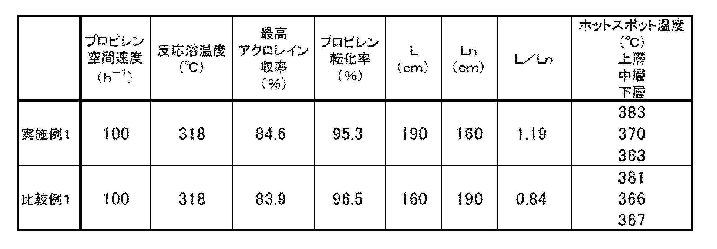
- the acrolein yield showed the highest value at 318 ° C., and the propylene conversion rate and the hot spot temperature of each catalyst layer at that time were obtained.
- the results are shown in Table 1.
- the hot spots of each catalyst layer are shown as the hot spot temperatures in Table 1.
- Example 2 Under the oxidation reaction conditions of Example 1, the catalyst layer was filled with 200 cm of the undiluted catalyst (F2) as the upper layer, and 150 cm of the undiluted catalyst (F4) was sequentially filled as the lower layer toward the raw material gas outlet.
- the supply amount of propylene, air, water, and nitrogen was set to 170 hr- 1, and the propylene was circulated so that the space velocity was 170 hr -1, and the reaction was started with the pressure on the outlet side of the reaction tube at the time of total gas flow being 75 kPaG.
- the oxidation reaction of propylene was carried out in the same manner as in Example 1.
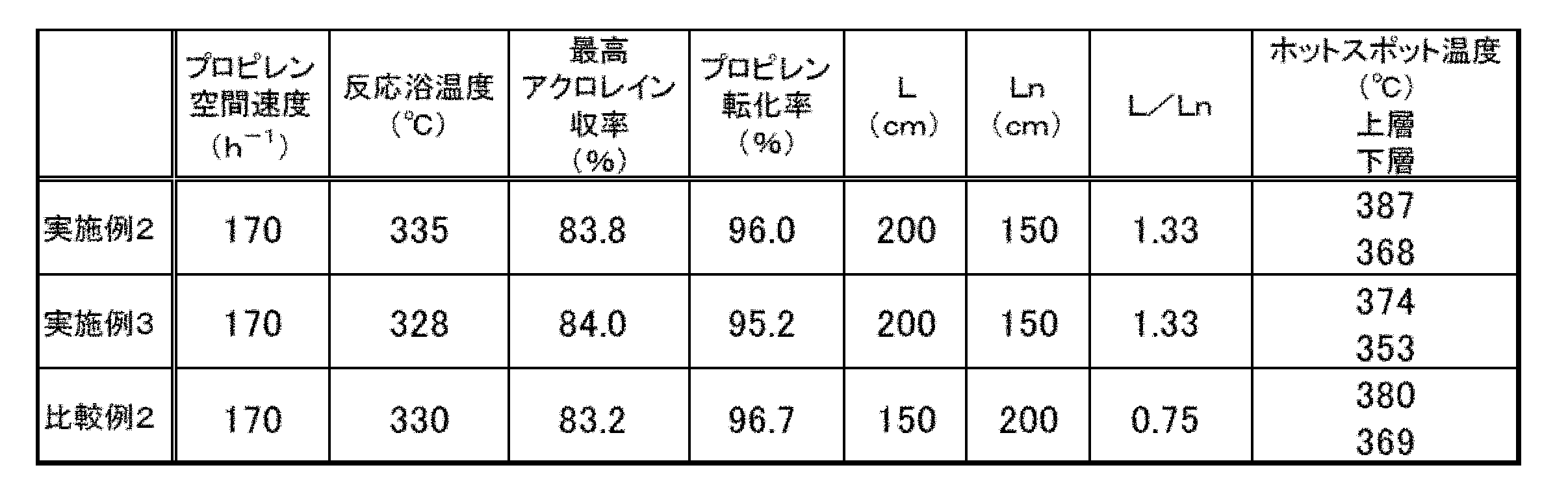
- the acrolein yield showed the highest value at 335 ° C., and the propylene conversion rate and the hot spot temperature of each catalyst layer at that time were obtained.
- the results are shown in Table 1.
- Example 3 Under the oxidation reaction conditions of Example 2, two layers of catalyst layers were packed by filling 200 cm of the undiluted catalyst (F5) as the upper layer and 150 cm of the undiluted catalyst (F6) as the lower layer toward the raw material gas outlet in sequence.
- the acrolein yield showed the highest value at 328 ° C., and the propylene conversion rate and the hot spot temperature of each catalyst layer at that time were obtained. The results are shown in Table 2.
- the performance in the region where the load applied to the catalyst is the same, such as the space velocity. Further, for example, even if the yield decreases by about 0.5% due to an increase in load, if the operation can be performed with twice the load, the target product can be obtained at about twice the speed, so that the operation can be performed with a high load. If possible, production efficiency can be greatly improved.
- Example 5 In Example 4, the oxidation reaction was carried out under the same conditions as in Example 4 except that the upper layer (F2) was filled with 71.4 mm and the lower layer (F4) was filled with 28.6 mm. The results are shown in Table 3.
- Example 4 the oxidation reaction was carried out under the same conditions as in Example 4 except that the upper layer (F2) was filled with 77.8 mm and the lower layer (F4) was filled with 22.2 mm. The results are shown in Table 3.
Landscapes
- Chemical & Material Sciences (AREA)
- Organic Chemistry (AREA)
- Engineering & Computer Science (AREA)
- Materials Engineering (AREA)
- Chemical Kinetics & Catalysis (AREA)
- Physics & Mathematics (AREA)
- Thermal Sciences (AREA)
- Catalysts (AREA)
- Organic Low-Molecular-Weight Compounds And Preparation Thereof (AREA)
- Low-Molecular Organic Synthesis Reactions Using Catalysts (AREA)
Abstract
固定床多管型反応器を用いて、アルケンを部分酸化して対応する不飽和アルデヒドを製造する不飽和アルデヒドの製造方法であって、 反応管のガス流れ方向に対しn分割(nは2以上)して形成される複数の触媒層を設け、 反応管ガス入口側から数えてn-1層目までの触媒層の充填長をL、反応管ガス入口側から数えてn層目の触媒層の充填長をLnとしたとき、L及びLnの関係が下記式(1)を満たし、 1<L/Ln≦3 (1) 反応管ガス入口側から数えてn-1層目までの触媒層に含まれる触媒活性成分の組成と、反応管ガス入口側から数えてn層目の触媒層に含まれる触媒活性成分の組成とが異なる、不飽和アルデヒドの製造方法。
Description
本発明は、アルケンを分子状酸素または分子状酸素含有ガスにより気相接触酸化し対応する不飽和アルデヒドを製造する方法に関する。
アルケンまたはその分子内脱水反応によりアルケン類を生じうるアルコールを原料にして対応する不飽和アルデヒドを製造する方法は工業的に広く実施されているが、なかでもプロピレンを分子状酸素により気相接触酸化して、アクロレインを合成する触媒に関し、従来から数多くの提案がなされている。
この気相系酸化反応においては、生産性の観点から収率が最も重要視される。そのため触媒の組成成分の改良として、鉄およびコバルト、ニッケルの原子比率に関する技術が特許文献1に、コバルトおよび/またはニッケルに対する鉄の原子比率に関する技術が許文献2に、モリブデンに対するそれぞれの元素の原子比率の最適化に加え、ビスマスに対するニッケル、アルカリ金属成分に対するニッケル、アルカリ金属成分に対するビスマス、それぞれの原子比率に関する技術が特許文献3に記載されている。また、モリブデンに対するビスマスの組成比の改良が特許文献4に記載されている。
また、この反応系は激しい発熱を伴うため、触媒層における局所的な高温部分(ホットスポット)の発生が大きな問題となっている。ホットスポットは、一般的には触媒層内温度の極大値のことを意味し、通常は原料濃度が高いガス入口側の触媒層で発生するが、入口側触媒の失活や、急激な外乱要因や様々な条件のばらつきによりガス出口側に位置する高活性な触媒層にも発生しうる。ここでいう外乱要因とは、例えば反応浴ジャケットに供給される熱媒体の流速の変化や気温による原料ガスの流量の変動を指す。
ホットスポットの発生は触媒寿命の短縮、過度の酸化反応による収率の低下、場合によっては暴走反応につながるため、ホットスポット温度を抑制するためにホットスポットが発生する部分に充填する触媒の活性を制御する技術がいくつか提案されている。
例えば特許文献5には担持量を変えて活性を調節した触媒を使用すること、触媒の焼成温度を変えて活性を調節した触媒を使用することでホットスポット温度を低下させる技術が開示されている。特許文献6には触媒の見かけ密度の比を変えることで活性を調節した触媒を使用する技術が開示されている。特許文献7には触媒成型体の不活性成分の含有量を変えるとともに、触媒成型体の占有容積、アルカリ金属の種類および/または量、触媒の焼成温度を変えることで活性を調節した触媒を使用する技術が開示されている。特許文献8には触媒成型体の占有容積を変えた反応帯を設け、すくなくとも一つの反応帯に不活性物質を混合する技術が開示されている。特許文献9には触媒の焼成温度を変えることで活性を調節した触媒を使用する技術が開示されている。特許文献10には触媒の占有容積と、焼成温度および/またはアルカリ金属の種類、量を変えることで活性を調節した触媒を使用する技術が開示されている。
しかしながら、上記手段をもって収率の改善をはかっても目的生成物の収率は十分とは言い難く、製造に要するアルケンの使用量を左右し製造コストに多大な影響を与えるため改善が求められている。また、低い収率で運転を継続することによって副生成物を大量に生成するため精製工程に大きな負荷を与え、精製工程にかかる時間および運転コストが上がってしまう問題が生じる。さらには副生成物の種類によっては、それらは触媒表面や触媒付近のガス流路に堆積する場合もあり、これらが触媒表面の必要な反応活性点を被覆してしまうことで触媒の活性を低下させるため、無理やり活性を上げる必要が生じ反応浴温度を上げざるを得なくなる。すると、触媒が熱的ストレスを受けることとなり、寿命の低下や選択率の低下を引き起こし、さらなる収率の低下を招くことにもなる。
さらに、ホットスポットの抑制をはじめとした安定稼働についても未だ対策は十分ではなく、たとえば工業プラントでは、反応器構造由来の除熱能力のばらつき、水平方向、垂直方向での熱媒温度分布、反応管ごとのガス流速分布が生じてしまうことがあり、全ての反応管内で同一の状態で触媒が使用されるということはほぼありえない。
工業プラントで使用された触媒を分析すると、原料ガス入口部分の触媒が集中して劣化している反応管や、全体にわたって触媒が緩やかに劣化している反応管、さらに驚くべきことに原料ガス出口部分の触媒が入口部分の触媒よりも劣化している反応管が見受けられることもある。これは、原料ガス出口側の触媒層のホットスポット温度が異常に高かった可能性を示唆しており、場合によっては暴走反応を引き起こす可能性がある。これは、前述した工業プラントにおける反応管径のばらつき、反応器の構造由来の除熱能力のばらつき、水平方向、垂直方向での熱媒温度分布、反応管ごとのガス流速分布により、原料炭化水素の転化率が異なり、温度分布の形状が異なったことが原因と予想される。様々なばらつき要因が重なってしまった場合でも、より安全に安定して長期にわたって反応を維持できる技術の開発が課題として挙げられた。仮に反応の異常によるプラント停止が発生すると、その期間中の未生産分による損失、異常な温度や雰囲気によっては触媒寿命が短縮され、暴走反応が起きた際には工業プラント設備そのものの損傷や事故など多大な損失を招く可能性がある。このように、収率、安定稼働ともに改善が望まれている。
これまでの製造技術として、反応管ガス入口側には活性の低い触媒を用い、反応管ガス出口側の触媒には活性の高い触媒を用い、ガス入口側よりもガス出口側付近の触媒層の充填長を長くする多層充填方法がとられている。
本発明者らは、これら上記の現状と課題に対して鋭意検討した結果、二層以上に分割した触媒層を有する充填にて反応を行う際、反応管ガス入口側に位置する活性の低い触媒層の目的生成物の選択率が特に高いことに着目した。そして、反応管ガス入口側の触媒層の充填長を反応管ガス出口側に位置する活性の高い触媒層の充填長よりも長くすることと、特定の触媒層間で触媒活性成分の組成を異ならせることとにより、不飽和アルデヒドの選択率が高くなり、かつ活性の高い出口側に位置する活性の高い触媒の占有割合を抑えることで様々な反応条件のばらつきや外乱因子により生じうる暴走反応を抑制しやすくなり、より高収率で安定的なプラント運転が可能であることを見出した。
即ち、本発明は、以下1)~7)に関する。
1)
固定床多管型反応器を用いて、アルケンを部分酸化して対応する不飽和アルデヒドを製造する不飽和アルデヒドの製造方法であって、
反応管のガス流れ方向に対しn分割(nは2以上)して形成される複数の触媒層を設け、
反応管ガス入口側から数えてn-1層目までの触媒層の充填長をL、反応管ガス入口側から数えてn層目の触媒層の充填長をLnとしたとき、L及びLnの関係が下記式(1)を満たし、
1<L/Ln≦3 (1)
反応管ガス入口側から数えてn-1層目までの触媒層に含まれる触媒活性成分の組成と、反応管ガス入口側から数えてn層目の触媒層に含まれる触媒活性成分の組成とが異なる、不飽和アルデヒドの製造方法。
2)
前記L及びLnの関係が下記式(2)を満たす、1)に記載の不飽和アルデヒドの製造方法。
1.1<L/Ln≦1.4 (2)
3)
触媒層に含まれる触媒の形状が球状である、1)又は2)に記載の不飽和アルデヒドの製造方法。
4)
原料中のアルケンの濃度が6~12容量%である、1)~3)のいずれかに記載の不飽和アルデヒドの製造方法。
5)
反応管中のそれぞれの触媒層が、下記式(3)で表される組成を有する触媒活性成分を含む触媒を含む、1)~4)のいずれかに記載の不飽和アルデヒドの製造方法。
Mo12 Bia Feb Coc Nid Xe Yf Zg Oh (3)
(Xはマグネシウム(Mg)、カルシウム(Ca)、マンガン(Mn)、銅(Cu)、亜鉛(Zn)、セリウム(Ce)及びサマリウム(Sm)からなる群から選ばれる少なくとも1種の元素であり、Yはホウ素(B)、リン(P)、砒素(As)、アンチモン(Sb)及びタングステン(W)からなる群から選ばれる少なくとも1種の元素であり、Zはナトリウム(Na)、カリウム(K)、ルビジウム(Rb)及びセシウム(Cs)からなる群より選ばれる少なくとも1種の元素であり、(a)から(g)は各成分の原子比率を表し、hは触媒成分の酸化度で決定される数値を表し、a=0.40~2.0、b=1~3、c=3~7.5、d=2~4、e=0~10、f=0~10、g=0.01~0.50、hは他の元素の酸化状態を満足させる数値で表記され、d/aが1以上9以下であり、かつd/gが5以上350以下であり、かつa/gが0.8以上90以下である。)
6)
n層目の触媒層に含まれる触媒が不活性物質で希釈されていない触媒である、1)~5)のいずれかに記載の不飽和アルデヒドの製造方法。
7)
触媒層に含まれる触媒が担持触媒である、1)~6)のいずれかに記載の不飽和アルデヒドの製造方法。
1)
固定床多管型反応器を用いて、アルケンを部分酸化して対応する不飽和アルデヒドを製造する不飽和アルデヒドの製造方法であって、
反応管のガス流れ方向に対しn分割(nは2以上)して形成される複数の触媒層を設け、
反応管ガス入口側から数えてn-1層目までの触媒層の充填長をL、反応管ガス入口側から数えてn層目の触媒層の充填長をLnとしたとき、L及びLnの関係が下記式(1)を満たし、
1<L/Ln≦3 (1)
反応管ガス入口側から数えてn-1層目までの触媒層に含まれる触媒活性成分の組成と、反応管ガス入口側から数えてn層目の触媒層に含まれる触媒活性成分の組成とが異なる、不飽和アルデヒドの製造方法。
2)
前記L及びLnの関係が下記式(2)を満たす、1)に記載の不飽和アルデヒドの製造方法。
1.1<L/Ln≦1.4 (2)
3)
触媒層に含まれる触媒の形状が球状である、1)又は2)に記載の不飽和アルデヒドの製造方法。
4)
原料中のアルケンの濃度が6~12容量%である、1)~3)のいずれかに記載の不飽和アルデヒドの製造方法。
5)
反応管中のそれぞれの触媒層が、下記式(3)で表される組成を有する触媒活性成分を含む触媒を含む、1)~4)のいずれかに記載の不飽和アルデヒドの製造方法。
Mo12 Bia Feb Coc Nid Xe Yf Zg Oh (3)
(Xはマグネシウム(Mg)、カルシウム(Ca)、マンガン(Mn)、銅(Cu)、亜鉛(Zn)、セリウム(Ce)及びサマリウム(Sm)からなる群から選ばれる少なくとも1種の元素であり、Yはホウ素(B)、リン(P)、砒素(As)、アンチモン(Sb)及びタングステン(W)からなる群から選ばれる少なくとも1種の元素であり、Zはナトリウム(Na)、カリウム(K)、ルビジウム(Rb)及びセシウム(Cs)からなる群より選ばれる少なくとも1種の元素であり、(a)から(g)は各成分の原子比率を表し、hは触媒成分の酸化度で決定される数値を表し、a=0.40~2.0、b=1~3、c=3~7.5、d=2~4、e=0~10、f=0~10、g=0.01~0.50、hは他の元素の酸化状態を満足させる数値で表記され、d/aが1以上9以下であり、かつd/gが5以上350以下であり、かつa/gが0.8以上90以下である。)
6)
n層目の触媒層に含まれる触媒が不活性物質で希釈されていない触媒である、1)~5)のいずれかに記載の不飽和アルデヒドの製造方法。
7)
触媒層に含まれる触媒が担持触媒である、1)~6)のいずれかに記載の不飽和アルデヒドの製造方法。
本発明によれば、アルケンまたはその分子内脱水反応によりアルケン類を生じうるアルコールを原料にして対応する不飽和アルデヒドを製造する場合において、工業プラントにおいても安全に安定して長期にわたって高い収率を維持することが可能となる。
[Ln、Lの関係]
本願発明は主に触媒層の充填長に関するものである。触媒層の充填長は、以下のように定義される。
Ln:反応管のガス流れ方向に対してn分割して触媒層を設けた際の、反応管ガス入口側から数えてn層目の充填長
L:反応管ガス入口側から数えてn-1層目までの充填長
本願発明は、上記Ln及びLの関係が上記式(1)で表された関係を有する。また、反応管ガス入口側から数えてn-1層目までの触媒層に含まれる触媒活性成分の組成と、反応管ガス入口側から数えてn層目の触媒層に含まれる触媒活性成分の組成とが異なる。これによって、不飽和アルデヒドの選択率を向上することができ、更には反応条件のばらつきや外乱により生じうる暴走反応を抑制しやすくなり、より高収率で安全かつ安定的なプラント運転を実現する。暴走反応を抑制することで、触媒の熱的ストレスも予防し、寿命の長期化も期待される。
本願発明は主に触媒層の充填長に関するものである。触媒層の充填長は、以下のように定義される。
Ln:反応管のガス流れ方向に対してn分割して触媒層を設けた際の、反応管ガス入口側から数えてn層目の充填長
L:反応管ガス入口側から数えてn-1層目までの充填長
本願発明は、上記Ln及びLの関係が上記式(1)で表された関係を有する。また、反応管ガス入口側から数えてn-1層目までの触媒層に含まれる触媒活性成分の組成と、反応管ガス入口側から数えてn層目の触媒層に含まれる触媒活性成分の組成とが異なる。これによって、不飽和アルデヒドの選択率を向上することができ、更には反応条件のばらつきや外乱により生じうる暴走反応を抑制しやすくなり、より高収率で安全かつ安定的なプラント運転を実現する。暴走反応を抑制することで、触媒の熱的ストレスも予防し、寿命の長期化も期待される。
上記式(1)をさらに好ましい範囲に限定すると、上記式(2)となる。
L/Lnの値は、小さすぎると十分な選択率が得られず、また大きすぎると反応浴温度を常用の範囲に低く保つことが難しくなり、高い反応浴温度が要求されてしまい、選択率が低下する可能性がある。
L/Lnの下限は、1より大きい値である。また、より好ましくは1.05より大きい値であり特に好ましくは1.1より大きい値である。また、上限値は、3である。より好ましい上限値は2であり、さらに好ましい上限値は1.5であり、特に好ましい上限値は1.4である。従って、L/Lnの値として最も好ましい範囲は、1.1より大きく1.4以下である。
L/Lnの値は、小さすぎると十分な選択率が得られず、また大きすぎると反応浴温度を常用の範囲に低く保つことが難しくなり、高い反応浴温度が要求されてしまい、選択率が低下する可能性がある。
L/Lnの下限は、1より大きい値である。また、より好ましくは1.05より大きい値であり特に好ましくは1.1より大きい値である。また、上限値は、3である。より好ましい上限値は2であり、さらに好ましい上限値は1.5であり、特に好ましい上限値は1.4である。従って、L/Lnの値として最も好ましい範囲は、1.1より大きく1.4以下である。
本願発明において使用する触媒層に含まれる触媒活性成分は、上述のように1層目からn-1層目までの触媒層とn層目の触媒層とで組成が異なるものである。特に、最も反応管ガス出口側に位置する触媒層(最下層)であるn層目の触媒層は触媒活性の観点よりカリウム(K)を含む触媒活性成分を含むことが好ましく、また1層目からn-1層目までの触媒層はセシウム(Cs)を含む触媒活性成分を含むことが好ましい。
具体的触媒活性成分の組成としては例えば以下の触媒活性成分を例示することができる。
具体的触媒活性成分の組成としては例えば以下の触媒活性成分を例示することができる。
[触媒について]
本願発明に用いる上層(反応管ガス入口側から1からn-1層目の触媒層)が含む触媒活性成分は、下記式(3)で表される複合金属酸化物触媒活性成分であることが好ましい。
Mo12 Bia Feb Coc Nid Xe Yf Zg Oh (3)
上記式(3)において、Xはマグネシウム(Mg)、カルシウム(Ca)、マンガン(Mn)、銅(Cu)、亜鉛(Zn)、セリウム(Ce)及びサマリウム(Sm)からなる群から選ばれる少なくとも1種の元素であり、Yはホウ素(B)、リン(P)、砒素(As)、アンチモン(Sb)及びタングステン(W)からなる群から選ばれる少なくとも1種の元素であり、Zはナトリウム(Na)、カリウム(K)、ルビジウム(Rb)及びセシウム(Cs)からなる群より選ばれる少なくとも1種の元素であり、(a)から(g)は各成分の原子比率を表し、hは触媒成分の酸化度で決定される数値を表し、a=0.40~2.0、b=1~3、c=3~7.5、d=2~4、e=0~10、f=0~10、g=0.01~0.50、hは他の元素の酸化状態を満足させる数値で表記され、d/aが1以上9以下であり、かつd/gが5以上350以下であり、かつa/gが0.8以上90以下である。
なお、本願において、「~」は以上、以下を意味し、すなわち「~」を挟んだ数値は含むものとする。
本願発明に用いる上層(反応管ガス入口側から1からn-1層目の触媒層)が含む触媒活性成分は、下記式(3)で表される複合金属酸化物触媒活性成分であることが好ましい。
Mo12 Bia Feb Coc Nid Xe Yf Zg Oh (3)
上記式(3)において、Xはマグネシウム(Mg)、カルシウム(Ca)、マンガン(Mn)、銅(Cu)、亜鉛(Zn)、セリウム(Ce)及びサマリウム(Sm)からなる群から選ばれる少なくとも1種の元素であり、Yはホウ素(B)、リン(P)、砒素(As)、アンチモン(Sb)及びタングステン(W)からなる群から選ばれる少なくとも1種の元素であり、Zはナトリウム(Na)、カリウム(K)、ルビジウム(Rb)及びセシウム(Cs)からなる群より選ばれる少なくとも1種の元素であり、(a)から(g)は各成分の原子比率を表し、hは触媒成分の酸化度で決定される数値を表し、a=0.40~2.0、b=1~3、c=3~7.5、d=2~4、e=0~10、f=0~10、g=0.01~0.50、hは他の元素の酸化状態を満足させる数値で表記され、d/aが1以上9以下であり、かつd/gが5以上350以下であり、かつa/gが0.8以上90以下である。
なお、本願において、「~」は以上、以下を意味し、すなわち「~」を挟んだ数値は含むものとする。
上記Xとしては、好ましくはマグネシウム(Mg)、カルシウム(Ca)、マンガン(Mn)、亜鉛(Zn)、およびセリウム(Ce)からなる群から選ばれる少なくとも1種の元素であり、更に好ましくはマグネシウム(Mg)、カルシウム(Ca)、亜鉛(Zn)およびセリウム(Ce)からなる群から選ばれる少なくとも1種の元素であり、特に好ましくはマグネシウム(Mg)、カルシウム(Ca)およびセリウム(Ce)からなる群から選ばれる少なくとも1種の元素である。
上記Yとしては、好ましくはホウ素(B)、リン(P)、アンチモン(Sb)及びタングステン(W)からなる群から選ばれる少なくとも1種の元素であり、更に好ましくはリン(P)、アンチモン(Sb)及びタングステン(W)からなる群から選ばれる少なくとも1種の元素であり、特に好ましくはアンチモン(Sb)及びタングステン(W)からなる群から選ばれる少なくとも1種の元素である。
上記Zとしては、好ましくはカリウム(K)、ルビジウム(Rb)、セシウム(Cs)からなる群より選ばれる少なくとも1種の元素であり、更に好ましくはカリウム(K)、セシウム(Cs)からなる群より選ばれる少なくとも1種の元素であり、特に好ましくはセシウム(Cs)である。
上記Yとしては、好ましくはホウ素(B)、リン(P)、アンチモン(Sb)及びタングステン(W)からなる群から選ばれる少なくとも1種の元素であり、更に好ましくはリン(P)、アンチモン(Sb)及びタングステン(W)からなる群から選ばれる少なくとも1種の元素であり、特に好ましくはアンチモン(Sb)及びタングステン(W)からなる群から選ばれる少なくとも1種の元素である。
上記Zとしては、好ましくはカリウム(K)、ルビジウム(Rb)、セシウム(Cs)からなる群より選ばれる少なくとも1種の元素であり、更に好ましくはカリウム(K)、セシウム(Cs)からなる群より選ばれる少なくとも1種の元素であり、特に好ましくはセシウム(Cs)である。
上記aとしては、好ましい上限は1.7であり、更に好ましい上限は1.5であり、特に好ましい上限は1.2である。また好ましい下限は、0.5であり、更に好ましい下限は0.6であり、特に好ましい下限は0.7である。
上記bとしては、好ましい上限は2.8であり、更に好ましい上限は2.5であり、特に好ましい上限は2.3である。また好ましい下限は、1.5であり、更に好ましい下限は1.6であり、特に好ましい下限は1.8である。
上記cとしては、好ましい上限は7.3であり、更に好ましい上限は7.2であり、特に好ましい上限は7.0である。また好ましい下限は、4.0であり、更に好ましい下限は5.0であり、特に好ましい下限は6.0である。
上記dとしては、好ましい上限は3.8であり、更に好ましい上限は3.5であり、特に好ましい上限は3.3である。また好ましい下限は、2.1であり、更に好ましい下限は2.2であり、特に好ましい下限は2.3である。
上記bとしては、好ましい上限は2.8であり、更に好ましい上限は2.5であり、特に好ましい上限は2.3である。また好ましい下限は、1.5であり、更に好ましい下限は1.6であり、特に好ましい下限は1.8である。
上記cとしては、好ましい上限は7.3であり、更に好ましい上限は7.2であり、特に好ましい上限は7.0である。また好ましい下限は、4.0であり、更に好ましい下限は5.0であり、特に好ましい下限は6.0である。
上記dとしては、好ましい上限は3.8であり、更に好ましい上限は3.5であり、特に好ましい上限は3.3である。また好ましい下限は、2.1であり、更に好ましい下限は2.2であり、特に好ましい下限は2.3である。
上記eとしては、好ましい上限は8.0であり、更に好ましい上限は5.0であり、特に好ましい上限は3.0である。また、好ましい下限は0である。
上記fとしては、好ましい上限は8.0であり、更に好ましい上限は5.0であり、特に好ましい上限は3.0である。また、好ましい下限は0である。
上記gとしては、好ましい上限は0.3であり、更に好ましい上限は0.2であり、特に好ましい上限は0.1である。また好ましい下限は、0.015であり、更に好ましい下限は0.02であり、特に好ましい下限は0.03である。
上記fとしては、好ましい上限は8.0であり、更に好ましい上限は5.0であり、特に好ましい上限は3.0である。また、好ましい下限は0である。
上記gとしては、好ましい上限は0.3であり、更に好ましい上限は0.2であり、特に好ましい上限は0.1である。また好ましい下限は、0.015であり、更に好ましい下限は0.02であり、特に好ましい下限は0.03である。
上記d/aとしては、好ましい上限は7.5であり、更に好ましい上限は5.7であり、特に好ましい上限は4.8である。また好ましい下限は、1.3であり、更に好ましい下限は1.5であり、特に好ましい下限は2.0である。
上記d/gとしては、好ましい上限は230であり、更に好ましい上限は160であり、特に好ましい上限は110である。また好ましい下限は、8であり、更に好ましい下限は14であり、特に好ましい下限は24である。
上記a/gとしては、好ましい上限は85であり、更に好ましい上限は70であり、特に好ましい上限は35である。また好ましい下限は、1.8であり、更に好ましい下限は4.0であり、特に好ましい下限は8.0である。
上記d/gとしては、好ましい上限は230であり、更に好ましい上限は160であり、特に好ましい上限は110である。また好ましい下限は、8であり、更に好ましい下限は14であり、特に好ましい下限は24である。
上記a/gとしては、好ましい上限は85であり、更に好ましい上限は70であり、特に好ましい上限は35である。また好ましい下限は、1.8であり、更に好ましい下限は4.0であり、特に好ましい下限は8.0である。
本願発明に用いる下層(反応管のガス流れ方向に対してn分割して触媒層を設けた際の反応管ガス入口側からn層目の触媒)が含む触媒活性成分は、特に限定されるものではないが、上記式(3)で表された触媒活性成分である場合が好ましい。すなわち、本願発明の好ましい態様は、反応管中の全触媒層に含まれる触媒活性成分が、上記式(3)で表される組成を有する触媒活性成分である態様である。
ただし、下層に用いる場合、上記Zとしては、好ましくはカリウム、ルビジウム、セシウムからなる群より選ばれる少なくとも1種の元素であり、更に好ましくはカリウム、セシウムからなる群より選ばれる少なくとも1種の元素であり、特に好ましくはカリウムである。
その他、X、Y、a、b、c、d、e、f、g、d/a、d/g、a/gは好ましいものを含めて、上記式(3)と同じである。
ただし、下層に用いる場合、上記Zとしては、好ましくはカリウム、ルビジウム、セシウムからなる群より選ばれる少なくとも1種の元素であり、更に好ましくはカリウム、セシウムからなる群より選ばれる少なくとも1種の元素であり、特に好ましくはカリウムである。
その他、X、Y、a、b、c、d、e、f、g、d/a、d/g、a/gは好ましいものを含めて、上記式(3)と同じである。
より具体的には、上層が下記式(3-1)で表された触媒活性成分を含み、及び/又は下層が下記式(3-2)で表された触媒活性成分を含むことが好ましい。ただし、上層に含まれる下記式(3-1)で表された触媒活性成分及び下層に含まれる下記式(3-2)で表された触媒活性成分の組成は互いに異なる。
Mo12 Bia1 Feb1 Coc1 Nid1 X1e1 Y1f1 Z1g1 Oh1 (3-1)
上記式(3-1)において、X1、Y1、(a1)から(h1)は、上記式(3)において定義されたX、Y、(a)から(h)と同様に定義され、Z1はカリウム(K)又はセシウム(Cs)であり、好ましくはZ1はセシウム(Cs)である。
Mo12 Bia2 Feb2 Coc2 Nid2 X2e2 Y2f2 Z2g2 Oh2 (3-2)
上記式(3-2)において、X2、Y2、(a2)から(h2)は、上記式(3)において定義されたX、Y、(a)から(h)と同様に定義され、Z2はカリウム(K)又はセシウム(Cs)であり、好ましくはZ2はカリウム(K)である。
Mo12 Bia1 Feb1 Coc1 Nid1 X1e1 Y1f1 Z1g1 Oh1 (3-1)
上記式(3-1)において、X1、Y1、(a1)から(h1)は、上記式(3)において定義されたX、Y、(a)から(h)と同様に定義され、Z1はカリウム(K)又はセシウム(Cs)であり、好ましくはZ1はセシウム(Cs)である。
Mo12 Bia2 Feb2 Coc2 Nid2 X2e2 Y2f2 Z2g2 Oh2 (3-2)
上記式(3-2)において、X2、Y2、(a2)から(h2)は、上記式(3)において定義されたX、Y、(a)から(h)と同様に定義され、Z2はカリウム(K)又はセシウム(Cs)であり、好ましくはZ2はカリウム(K)である。
本願発明に用いる触媒層に含まれる触媒の形状は、特に制限されるものではなく、球状、円柱状、リング状、粉末状等を用いることができるが、特に好ましくは球状である。
なお、2層充填の場合には、上記上層に含まれる触媒、下層に含まれる触媒共に不活性物質を用いて希釈したものであっても良いが、上層、下層ともに希釈しない方法がより好ましい。
また、3層以上(n≧3)の触媒層を設ける場合、1層目、n層目以外の触媒層(以下中層と表現する)に用いる触媒活性成分は、上記式(3)で表される複合金属酸化物触媒活性成分であっても、これらと全く異なる組成を有する触媒であっても良いが、上記式(3)で表される複合金属酸化物触媒である場合が好ましく、その場合には、必要に応じ不活性物質による希釈率を変えることによって中層を形成することも出来る。また、上層及び中層に上記式(3-1)で表される触媒活性成分を用い、下層に上記式(3-2)で表される触媒活性成分を用いると好ましい。本願発明の触媒層の数としては、2層又は3層である場合が好ましく、2層である場合が特に好ましい。
不活性物質による希釈率として、好ましい範囲を以下に記載する。ここでいう希釈率とは、触媒と不活性物質とにより構成される触媒層のうち触媒が占有する質量比率を示す数値であり、例えば触媒層が80質量%希釈とは触媒が80質量%、不活性物質が20質量%であることを意味する。なお、後述する触媒の製造方法において説明するように、触媒活性成分を不活性担体に担持して触媒とした場合は、不活性担体を含めた触媒の質量を基に希釈率を算出する。以下、n=3の場合を例に、好ましい形態を記載するが、本願発明の本質は反応管をガス流れ方向にn分割した触媒の、n番目の触媒層の充填長に対するその他の触媒層の充填長を一定の範囲内に収める事であるので、これに限定されるものでは無い。
上層(最も原料ガス入口側に配置される触媒層):式(3)で記載される触媒活性成分を含む触媒を不活性物質で50質量%~100質量%に希釈した触媒が好ましく、60質量%~100質量%に希釈した触媒が更に好ましく、70質量%~100質量%に希釈した触媒が最も好ましい。
中層(原料ガス入口側から2番目からn-1番目に配置される触媒層):式(3)で記載される触媒活性成分を含む触媒を不活性物質で80質量%~100質量%に希釈した触媒が好ましく、85質量%~100質量%に希釈した触媒が更に好ましく、90質量%~100質量%に希釈した触媒が最も好ましい。
下層(原料ガス入口側からn番目に配置される、反応管の最もガス出口側に位置する触媒層):70質量%~100質量%に希釈した触媒が好ましく、75質量%~100質量%に希釈した触媒が更に好ましく、80質量%~100質量%に希釈した触媒が最も好ましい。なお、下層は活性を高める方が好ましく、希釈率は100質量%である場合が最も好ましい。
なお4層以上(n≧4)の触媒層を設ける場合には、この中層が複数存在することになり、触媒組成を変更しても良いし前記希釈率の範囲内で希釈率を変更して、追加の層を形成しても良い。
中層(原料ガス入口側から2番目からn-1番目に配置される触媒層):式(3)で記載される触媒活性成分を含む触媒を不活性物質で80質量%~100質量%に希釈した触媒が好ましく、85質量%~100質量%に希釈した触媒が更に好ましく、90質量%~100質量%に希釈した触媒が最も好ましい。
下層(原料ガス入口側からn番目に配置される、反応管の最もガス出口側に位置する触媒層):70質量%~100質量%に希釈した触媒が好ましく、75質量%~100質量%に希釈した触媒が更に好ましく、80質量%~100質量%に希釈した触媒が最も好ましい。なお、下層は活性を高める方が好ましく、希釈率は100質量%である場合が最も好ましい。
なお4層以上(n≧4)の触媒層を設ける場合には、この中層が複数存在することになり、触媒組成を変更しても良いし前記希釈率の範囲内で希釈率を変更して、追加の層を形成しても良い。
なお本願発明における好ましい態様は、下記1)~2)である。
1)n=2であり、上層が式(3)で表される触媒活性成分を含む触媒であり、希釈率が100質量%であり、Z成分がセシウムであり、下層が式(3)で表される触媒活性成分を含む触媒であり、Z成分がカリウムであり、希釈率が100質量%である。
2)n=3であり、中層が式(3)で表される触媒活性成分を含む触媒であり、希釈率が100質量%であり、Z成分がセシウムであり、上層が中層触媒を不活性物質で希釈した触媒であり、下層が式(3)で表される触媒活性成分を含む触媒であり、Z成分がカリウムであり、希釈率が100質量%である。
1)n=2であり、上層が式(3)で表される触媒活性成分を含む触媒であり、希釈率が100質量%であり、Z成分がセシウムであり、下層が式(3)で表される触媒活性成分を含む触媒であり、Z成分がカリウムであり、希釈率が100質量%である。
2)n=3であり、中層が式(3)で表される触媒活性成分を含む触媒であり、希釈率が100質量%であり、Z成分がセシウムであり、上層が中層触媒を不活性物質で希釈した触媒であり、下層が式(3)で表される触媒活性成分を含む触媒であり、Z成分がカリウムであり、希釈率が100質量%である。
上記不活性物質とは、シリカ、アルミナ、チタニア、ジルコニア、ニオビア、シリカアルミナ、炭化ケイ素、炭化物、およびこれらの混合物など公知の物質が挙げられる。このうち、好ましくはシリカ、アルミナ、またはこれらの混合物であり、特に好ましくはシリカ、アルミナであり、最も好ましくはシリカとアルミナの混合物である。
また、不活性物質の形状は、特に制限はないが球状であるものが好ましく、その平均粒子径は3mm~10mmであるものが好ましく、さらに好ましくは3.5mm~9mmである。特に好ましくは、4mm~8mmである。
また、不活性物質の形状は、特に制限はないが球状であるものが好ましく、その平均粒子径は3mm~10mmであるものが好ましく、さらに好ましくは3.5mm~9mmである。特に好ましくは、4mm~8mmである。
[触媒の製造方法について]
本願発明に用いる触媒は、例えば下記工程a)~e)によって製造することができる。
<工程a) 調合>
一般に触媒活性成分を構成する各元素の出発原料は特に制限されるものではない。モリブデン成分原料としては三酸化モリブデンのようなモリブデン酸化物、モリブデン酸、モリブデン酸アンモニウムのようなモリブデン酸又はその塩、リンモリブデン酸、ケイモリブデン酸のようなモリブデンを含むヘテロポリ酸又はその塩などを用いることができるが、好ましくはモリブデン酸アンモニウムを使用した場合で、高性能な触媒を得ることができる。特にモリブデン酸アンモニウムには、ジモリブデン酸アンモニウム、テトラモリブデン酸アンモニウム、ヘプタモリブデン酸アンモニウム等、複数種類の化合物が存在するが、その中でもヘプタモリブデン酸アンモニウムを使用した場合が最も好ましい。
本願発明に用いる触媒は、例えば下記工程a)~e)によって製造することができる。
<工程a) 調合>
一般に触媒活性成分を構成する各元素の出発原料は特に制限されるものではない。モリブデン成分原料としては三酸化モリブデンのようなモリブデン酸化物、モリブデン酸、モリブデン酸アンモニウムのようなモリブデン酸又はその塩、リンモリブデン酸、ケイモリブデン酸のようなモリブデンを含むヘテロポリ酸又はその塩などを用いることができるが、好ましくはモリブデン酸アンモニウムを使用した場合で、高性能な触媒を得ることができる。特にモリブデン酸アンモニウムには、ジモリブデン酸アンモニウム、テトラモリブデン酸アンモニウム、ヘプタモリブデン酸アンモニウム等、複数種類の化合物が存在するが、その中でもヘプタモリブデン酸アンモニウムを使用した場合が最も好ましい。
ビスマス成分原料としては硝酸ビスマス、次炭酸ビスマス、硫酸ビスマス、酢酸ビスマスなどのビスマス塩、三酸化ビスマス、金属ビスマスなどを用いることができるが、より好ましくは硝酸ビスマスであり、これを使用した場合に高性能な触媒が得られる。鉄、コバルト、ニッケル及びその他の元素の原料としては通常は酸化物あるいは強熱することにより酸化物になり得る硝酸塩、炭酸塩、有機酸塩、水酸化物等又はそれらの混合物を用いることができる。例えば、鉄成分原料とコバルト成分原料及び/又はニッケル成分原料を所望の比率で10~80℃の条件下にて水に溶解混合し、20~90℃の条件下にて別途調合されたモリブデン成分原料およびZ成分原料水溶液もしくはスラリーと混合し、20~90℃の条件下にて1時間程度加熱撹拌した後、ビスマス成分原料を溶解した水溶液と、必要に応じX成分原料、Y成分原料とを添加して触媒成分を含有する水溶液またはスラリーを得る。以降、両者をまとめて調合液(A)と称する。
ここで、調合液(A)は必ずしもすべての触媒活性成分構成元素を含有する必要は無く、その一部の元素または一部の量を以降の工程で添加してもよい。また、調合液(A)を調合する際に各成分原料を溶解する水の量や、溶解のために硫酸や硝酸、塩酸、酒石酸、酢酸などの酸を加える場合には、原料が溶解するのに十分な水溶液中の酸濃度が、例えば5質量%~99質量%の範囲で調合に適していないと、調合液(A)の形態が粘土状の塊となる場合がある。この場合では、優れた触媒が得られない。調合液(A)の形態としては水溶液またはスラリーが、優れた触媒が得られるため、好ましい。
<工程b) 乾燥>
次いで上記で得られた調合液(A)を乾燥し、乾燥紛体とする。乾燥方法は、調合液(A)を完全に乾燥できる方法であれば特に制限はないが、例えばドラム乾燥、凍結乾燥、噴霧乾燥、蒸発乾固等が挙げられる。これらのうち本発明においては、スラリーから短時間に紛体又は顆粒に乾燥することができる噴霧乾燥が特に好ましい。噴霧乾燥の乾燥温度はスラリーの濃度、送液速度等によって異なるが概ね乾燥機の出口における温度が70~150℃である。また、この際得られる乾燥紛体の平均粒径が10~700μmとなるよう乾燥するのが好ましい。こうして乾燥紛体(B)を得る。
次いで上記で得られた調合液(A)を乾燥し、乾燥紛体とする。乾燥方法は、調合液(A)を完全に乾燥できる方法であれば特に制限はないが、例えばドラム乾燥、凍結乾燥、噴霧乾燥、蒸発乾固等が挙げられる。これらのうち本発明においては、スラリーから短時間に紛体又は顆粒に乾燥することができる噴霧乾燥が特に好ましい。噴霧乾燥の乾燥温度はスラリーの濃度、送液速度等によって異なるが概ね乾燥機の出口における温度が70~150℃である。また、この際得られる乾燥紛体の平均粒径が10~700μmとなるよう乾燥するのが好ましい。こうして乾燥紛体(B)を得る。
<工程c) 予備焼成>
得られた乾燥紛体(B)は空気流通下で200℃から600℃で、好ましくは300℃から600℃で焼成することで触媒の成型性、機械的強度、触媒性能が向上する傾向がある。焼成時間は1時間から12時間が好ましい。こうして予備焼成紛体(C)を得る。
得られた乾燥紛体(B)は空気流通下で200℃から600℃で、好ましくは300℃から600℃で焼成することで触媒の成型性、機械的強度、触媒性能が向上する傾向がある。焼成時間は1時間から12時間が好ましい。こうして予備焼成紛体(C)を得る。
<工程d) 成型>
成型方法に特に制限はないが円柱状、リング状に成型する際には打錠成型機、押し出し成型機などを用いた方法が好ましい。さらに好ましくは、球状に成型する場合であり、成型機で予備焼成紛体(C)を球形に成型しても良いが、予備焼成紛体(C)(必要により成型助剤、強度向上剤を含む)を不活性なセラミック等の担体に担持させる方法が好ましい。ここで担持方法としては転動造粒法、遠心流動コーティング装置を用いる方法、ウォッシュコート方法等が広く知られている。予備焼成紛体(C)が担体に均一に担持できる方法で有れば特に限定されないが、触媒の製造効率や調製される触媒の性能を考慮した場合、より好ましくは固定円筒容器の底部に、平らな、あるいは凹凸のある円盤を有する装置で、円盤を高速で回転させることにより、容器内にチャージされた担体を、担体自体の自転運動と公転運動の繰り返しにより激しく撹拌させ、ここに予備焼成紛体(C)並びに必要により、成型助剤及び/または強度向上剤を添加することにより紛体成分を担体に担持させる方法が好ましい。
成型方法に特に制限はないが円柱状、リング状に成型する際には打錠成型機、押し出し成型機などを用いた方法が好ましい。さらに好ましくは、球状に成型する場合であり、成型機で予備焼成紛体(C)を球形に成型しても良いが、予備焼成紛体(C)(必要により成型助剤、強度向上剤を含む)を不活性なセラミック等の担体に担持させる方法が好ましい。ここで担持方法としては転動造粒法、遠心流動コーティング装置を用いる方法、ウォッシュコート方法等が広く知られている。予備焼成紛体(C)が担体に均一に担持できる方法で有れば特に限定されないが、触媒の製造効率や調製される触媒の性能を考慮した場合、より好ましくは固定円筒容器の底部に、平らな、あるいは凹凸のある円盤を有する装置で、円盤を高速で回転させることにより、容器内にチャージされた担体を、担体自体の自転運動と公転運動の繰り返しにより激しく撹拌させ、ここに予備焼成紛体(C)並びに必要により、成型助剤及び/または強度向上剤を添加することにより紛体成分を担体に担持させる方法が好ましい。
尚、担持に際して、バインダーを使用するのが好ましい。用いうるバインダーの具体例としては、水やエタノール、メタノール、プロパノール、多価アルコール、高分子系バインダーのポリビニルアルコール、無機系バインダーのシリカゾル水溶液等が挙げられるが、エタノール、メタノール、プロパノール、多価アルコールが好ましく、エチレングリコール等のジオールやグリセリン等のトリオール等がより好ましい。グリセリン水溶液を適量使用することにより成型性が良好となり、機械的強度の高い、高性能な触媒が得られ、具体的にはグリセリンの濃度5質量%以上の水溶液を使用した場合に特に高性能な触媒が得られる。これらバインダーの使用量は、予備焼成紛体(C)100質量部に対して通常2~80質量部である。不活性担体は、通常、直径2~8mm程度のものを使用し、これに予備焼成紛体(C)を担持させる。その担持率は触媒使用条件、たとえば反応原料の空間速度、原料濃度などの反応条件を考慮して決定されるものであるが、通常20質量%から80質量%である。ここで担持率は以下の式で表記される。
担持率(質量%)=
100×〔成型に使用した予備焼成紛体(C)の質量/(成型に使用した予備焼成紛体(C)の質量+成型に使用した不活性担体の質量)〕 (4)
100×〔成型に使用した予備焼成紛体(C)の質量/(成型に使用した予備焼成紛体(C)の質量+成型に使用した不活性担体の質量)〕 (4)
<工程e) 本焼成>
工程d)により得られた成型体(D)は200~600℃の温度で1~12時間程度焼成することで触媒活性、選択性が向上する傾向にある。焼成温度は400℃以上600℃以下が好ましく、500℃以上600℃以下がより好ましい。流通させるガスとしては空気が簡便で好ましいが、その他に不活性ガスとして窒素、二酸化炭素、還元雰囲気にするための窒素酸化物含有ガス、アンモニア含有ガス、水素ガスおよびそれらの混合物を使用することも可能である。こうして触媒(E)を得る。
工程d)により得られた成型体(D)は200~600℃の温度で1~12時間程度焼成することで触媒活性、選択性が向上する傾向にある。焼成温度は400℃以上600℃以下が好ましく、500℃以上600℃以下がより好ましい。流通させるガスとしては空気が簡便で好ましいが、その他に不活性ガスとして窒素、二酸化炭素、還元雰囲気にするための窒素酸化物含有ガス、アンモニア含有ガス、水素ガスおよびそれらの混合物を使用することも可能である。こうして触媒(E)を得る。
[原料中のアルケンの濃度]
本発明におけるアルケンの接触気相酸化反応は、原料ガス組成として6~12容量%のアルケン(より好ましくは6~10容量%)、5~18容量%の分子状酸素、0~60容量%の水蒸気及び20~70容量%の不活性ガス、例えば窒素、炭酸ガスなどからなる混合ガスを前記のようにして調製された触媒上に250~450℃の温度範囲及び常圧~10気圧の圧力下、好ましくは常圧~5気圧下、より好ましくは常圧から3気圧下で、0.5~10秒の接触時間で導入することによって行われる。
本発明におけるアルケンの接触気相酸化反応は、原料ガス組成として6~12容量%のアルケン(より好ましくは6~10容量%)、5~18容量%の分子状酸素、0~60容量%の水蒸気及び20~70容量%の不活性ガス、例えば窒素、炭酸ガスなどからなる混合ガスを前記のようにして調製された触媒上に250~450℃の温度範囲及び常圧~10気圧の圧力下、好ましくは常圧~5気圧下、より好ましくは常圧から3気圧下で、0.5~10秒の接触時間で導入することによって行われる。
なお、本発明において、アルケンとは、その分子内脱水反応においてアルケンを生じるアルコール類、例えばターシャリーブチルアルコールも含めるものとする。アルケンなどの反応基質の触媒体積に対する空間速度(反応基質供給速度(NL/hr)/触媒充填空間容積(L))は高い方が生産効率の点から好ましいが、あまり高くなると目的生成物の収率が低下する場合があること、触媒の寿命が短縮することなどから実際上は、40~200hr-1が好ましく、より好ましくは60~180hr-1の範囲である。ここでNLは反応基質の標準状態における容積を表す。また、アルケンの転化率としては、アクロレイン収率が得られる転化率付近が好ましく、通常は90~99.9%、好ましくは95~99.5%、より好ましくは96~99%である。
本願発明においては、反応管の原料ガス流れ方向に複数個にn分割して形成された触媒層を設け、上記複数種の触媒を原料ガス流れ方向の原料入口部から出口部に向かって活性がより高くなるよう配置するのが好ましい。分割数nに特に制限はないが、通常2~5、好ましくは2~3である。
多層充填においては、反応管ガス出口側の触媒層の充填長がその他の触媒層の充填長の合算よりも長いことが一般的である。その際、入口側での発熱を嫌い必ずガス出口側ほど活性が高い触媒を配置する設計とされるが出口側の高活性触媒の充填長が長いと多くのデメリットが生じ得る。まず、反応管内における高活性触媒の原料転化率への寄与が高まると、原料および目的生成物である不飽和アルデヒドが過度な酸化を受け、目的生成物の選択率および収率が低下してしまう。さらには、外乱要因や様々な条件のばらつきによって反応が不安定になった際には、出口側の高活性な触媒の充填長が長くなるほど、出口側でホットスポットを生じる可能性が高まり、結果として暴走反応を引き起こす可能性が高まる。また一方で、発明者の実施した工業プラントの使用済触媒の分析において、多層充填された触媒のうち、劣化しているのは主にガス入口側触媒層であることが多く、反応ガス出口側の触媒が劣化していることは稀であった。このことから、反応ガス入口側からn-1層目までに位置する触媒は多層充填の触媒寿命に影響を与えうる。
本発明の効果を得ようとして、あまりにも反応ガス出口側の触媒層を短くすると、触媒層全体の活性が低下することによって常用の原料転化率を得て目的生成物を得るために必要な反応浴温度が上昇し過ぎてしまい、入口側からn-1層目のホットスポットが高温になりガス入口側の触媒の劣化や性能低下を生じる。また場合によってはガス入口側触媒の早期劣化によって、ガス出口側の高活性な触媒層に高いホットスポットを生じさせ、目的生成物の選択率および収率の急激な低下を引き起こす可能性もある。そのためガス入口側とガス出口側の触媒のバランスを考慮し、出口側の触媒層を短くし過ぎて触媒層全体の活性が低下し、反応浴温度が過度に上昇しないようにすることも必要である。反応浴温度は触媒の特性や、使用条件、必要とする触媒寿命などにより適宜設定されるため一概には言えないが、反応初期の浴温度としては350℃以下が好ましく、340℃以下がより好ましい。
工業プラントにおいて、上記のような製造方法を実施することにより不飽和アルデヒドの収率を改善し、かつ高活性なガス出口側の暴走を抑制することができ、長期にわたり工業プラントで安定した収率と運転が可能となる。この効果は、比較的選択率の高い触媒層の占有率が比較的活性の高い触媒層の占有率を上回ることで反応への高選択な触媒の寄与が高まることに起因すると考えられる。
以下、具体例を挙げて実施例を示したが、本発明はその趣旨を逸脱しない限り実施例に限定されるものではない。
なお以下において、アクロレイン収率の定義は、次の通りである。
アクロレイン収率(モル%)
=(生成したアクロレインのモル数/供給したプロピレンのモル数)×100
アクロレイン収率(モル%)
=(生成したアクロレインのモル数/供給したプロピレンのモル数)×100
L及び/又はLnを求める際に、充填長比は設計値ではなく実測値を用いるのが好ましい。プラントにおいては、反応管が複数本ある場合が多いため、その一部の計測結果から得られる平均値を用いることもできる。L及び/又はLnの測定は、例えば反応管上部から触媒を下部に向けて順に充填していき、その各層の上部の空間長さをメジャーなどを用い計測することで算出出来る。
[製造例 (触媒の調製)]
蒸留水3000質量部を加熱攪拌しながらモリブデン酸アンモニウム423.7質量部と硝酸カリウム0.73質量部を溶解して水溶液(A1)を得た。別に、硝酸コバルト378.4質量部、硝酸ニッケル139.6質量部、硝酸第二鉄161.6質量部を蒸留水1000質量部に溶解して水溶液(B1)を、また、濃硝酸81質量部を加えて酸性にした蒸留水200質量部に硝酸ビスマス97.1質量部を溶解して水溶液(C1)をそれぞれ調製した。上記水溶液(A1)に(B1)、(C1)を順次、激しく攪拌しながら混合し、生成した懸濁液を、スプレードライヤーを用いて乾燥し440℃で6時間焼成し予備焼成粉末(D2)を得た。このときの触媒活性成分の酸素を除いた組成比は原子比でMo=12、Bi=1.0、Ni=3.0、Fe=2.0、Co=6.5、K=0.05であった。
蒸留水3000質量部を加熱攪拌しながらモリブデン酸アンモニウム423.7質量部と硝酸カリウム0.73質量部を溶解して水溶液(A1)を得た。別に、硝酸コバルト378.4質量部、硝酸ニッケル139.6質量部、硝酸第二鉄161.6質量部を蒸留水1000質量部に溶解して水溶液(B1)を、また、濃硝酸81質量部を加えて酸性にした蒸留水200質量部に硝酸ビスマス97.1質量部を溶解して水溶液(C1)をそれぞれ調製した。上記水溶液(A1)に(B1)、(C1)を順次、激しく攪拌しながら混合し、生成した懸濁液を、スプレードライヤーを用いて乾燥し440℃で6時間焼成し予備焼成粉末(D2)を得た。このときの触媒活性成分の酸素を除いた組成比は原子比でMo=12、Bi=1.0、Ni=3.0、Fe=2.0、Co=6.5、K=0.05であった。
その後、予備焼成粉末(D2)100質量部に結晶セルロース5質量部を混合した粉末を不活性担体(アルミナ、シリカを主成分とする直径4.5mmの球状物質)に、上記式(4)で定義される担持率が、50質量%になるように、成型に使用する担体質量および予備焼成粉末質量を調整した。20質量%グリセリン水溶液をバインダーとして使用し、直径5.2mmの球状に担持成型して担持触媒(E3)を得た。この担持触媒(E3)を、焼成温度530℃で、4時間空気雰囲気下で焼成することで触媒(F3)を得た。また、担持触媒(E3)と同様にして担持率が50質量%になるように、直径4.0mmの担体に球状に担持して直径4.7mmの担持触媒(E4)を得た。担持触媒(E4)を焼成温度530℃で4時間焼成することで触媒(F4)を得た。
上記の予備焼成粉末(D2)と同様の手法に従って、ただし硝酸カリウムの代わりに硝酸セシウムを用いて、予備焼成粉末(D1)を得た。得られた予備焼成粉末(D1)の触媒活性成分の酸素を除いた組成比は原子比でMo=12、Bi=1.0、Ni=3.0、Fe=2.0、Co=6.5、Cs=0.03であった。この予備焼成粉末(D1)を担持触媒(E3)と同様の手法に従って、担持成型して担持触媒(E1)を得た。また、予備焼成粉末(D1)を担持率が40質量%になるように、直径4.5mmの担体に球状に担持して直径5.0mmの担持触媒(E2)を得た。この担持触媒(E1)および(E2)を、焼成温度530℃で4時間、空気雰囲気下で焼成することで触媒それぞれ(F1)および(F2)を得た。
さらに、上記の予備焼成粉末(D1)を得た手法において、触媒活性成分の酸素を除いた組成比を原子比でMo=12、Bi=0.7、Ni=2.5、Fe=2.0、Co=7.0、Cs=0.08となるように上記配合比率を変化させて、予備焼成粉末(D3)を得た。予備焼成粉末(D1)および(D3)を担持触媒(E3)と同様の手法に従って、担持率が50質量%になるように、直径4.0mmの担体に球状に担持して直径4.7mmの担持触媒(E5)および(E6)を得た。この担持触媒(E5)および(E6)を、焼成温度530℃で4時間、空気雰囲気下でそれぞれ焼成することで触媒(F5)および(F6)を得た。
[実施例1]
上記のようにして調製した触媒(F1)から触媒(F6)を使用して、プロピレンの酸化反応を実施した。なお、実施例にて使用する、反応管原料ガス入口側の触媒(F1)または(F2)と、反応管原料ガス出口側触媒(F3)または(F4)とでは触媒活性成分の組成が異なるが、ともに一般式(3)に記載の組成範囲に含まれる。
上記のようにして調製した触媒(F1)から触媒(F6)を使用して、プロピレンの酸化反応を実施した。なお、実施例にて使用する、反応管原料ガス入口側の触媒(F1)または(F2)と、反応管原料ガス出口側触媒(F3)または(F4)とでは触媒活性成分の組成が異なるが、ともに一般式(3)に記載の組成範囲に含まれる。
熱媒体として溶融塩を循環させるジャケット及び触媒層温度を測定するための熱電対を管軸に設置した、内径25mmのステンレス製反応器の原料ガス入口側より直径5.2mmのシリカアルミナ球を20cm充填した。そして順次ガス出口方向へ向かって、上層(原料ガス入口側)として、触媒(F1)とシリカアルミナ混合物不活性球状担体とを質量比85:15で混合した希釈触媒(85質量%希釈)を80cm、中層として無希釈の触媒(F1)を110cm、下層として無希釈の触媒(F3)を160cm、それぞれ充填した。これにより触媒層を3層構成とし、L/Ln=1.19にした。反応浴温度を315℃にし、ここに原料モル比率が、プロピレン:酸素(供給される空気中に含まれる酸素):水:窒素(空気とは別に供給される窒素)=1:1.7:1:2.4となるようにプロピレン、空気、水、窒素の供給量を設定した。なお、当該供給原料中のプロピレン濃度(容量%)は、1/(1+(1.7/0.21)+1+2.4)×100=8容量%であった。なお、後述する実施例2及び実施例4における供給原料中のプロピレン濃度(容量%)の捉え方は本実施例のものと同様である。当該供給原料をプロピレンの空間速度が100hr-1となるよう流通させ、その全ガス流通時における反応管出口側の圧力が50kPaGとして反応開始後300時間経過したとき、反応浴温度を変化させて、プロピレンの酸化反応を実施した。反応浴温度を変化させて反応成績を調べた結果、318℃においてアクロレイン収率が最高値を示し、そのときのプロピレン転化率および各触媒層のホットスポット温度を得た。結果を表1に示す。なお、表1におけるホットスポットの温度として、各触媒層それぞれのホットスポットを記載した。
[実施例2]
実施例1の酸化反応条件において、上層として無希釈の触媒(F2)を200cm充填し、順次原料ガス出口へ向かって下層として無希釈の触媒(F4)を150cm充填することにより、触媒層を2層構成とし、L/Ln=1.33にした。原料モル比率が、プロピレン:酸素(供給される空気中に含まれる酸素):水:窒素(空気とは別に供給される窒素)=1:2.0:0.7:4.0となるようにプロピレン、空気、水、窒素の供給量を設定し、プロピレンの空間速度が170hr-1となるよう流通させ、その全ガス流通時における反応管出口側の圧力が75kPaGとして反応を開始した以外は、実施例1と同様の方法でプロピレンの酸化反応を実施した。反応浴温度を変化させて反応成績を調べた結果、335℃においてアクロレイン収率が最高値を示し、そのときのプロピレン転化率および各触媒層のホットスポット温度を得た。結果を表1に示す。
実施例1の酸化反応条件において、上層として無希釈の触媒(F2)を200cm充填し、順次原料ガス出口へ向かって下層として無希釈の触媒(F4)を150cm充填することにより、触媒層を2層構成とし、L/Ln=1.33にした。原料モル比率が、プロピレン:酸素(供給される空気中に含まれる酸素):水:窒素(空気とは別に供給される窒素)=1:2.0:0.7:4.0となるようにプロピレン、空気、水、窒素の供給量を設定し、プロピレンの空間速度が170hr-1となるよう流通させ、その全ガス流通時における反応管出口側の圧力が75kPaGとして反応を開始した以外は、実施例1と同様の方法でプロピレンの酸化反応を実施した。反応浴温度を変化させて反応成績を調べた結果、335℃においてアクロレイン収率が最高値を示し、そのときのプロピレン転化率および各触媒層のホットスポット温度を得た。結果を表1に示す。
[実施例3]
実施例2の酸化反応条件において、上層として無希釈の触媒(F5)を200cm充填し、順次原料ガス出口へ向かって下層として無希釈の触媒(F6)を150cm充填することにより触媒層を2層構成とする以外は、実施例1と同様の方法でプロピレンの酸化反応を実施した。L/Ln=1.33であった。反応浴温度を変化させて反応成績を調べた結果、328℃においてアクロレイン収率が最高値を示し、そのときのプロピレン転化率および各触媒層のホットスポット温度を得た。結果を表2に示す。
実施例2の酸化反応条件において、上層として無希釈の触媒(F5)を200cm充填し、順次原料ガス出口へ向かって下層として無希釈の触媒(F6)を150cm充填することにより触媒層を2層構成とする以外は、実施例1と同様の方法でプロピレンの酸化反応を実施した。L/Ln=1.33であった。反応浴温度を変化させて反応成績を調べた結果、328℃においてアクロレイン収率が最高値を示し、そのときのプロピレン転化率および各触媒層のホットスポット温度を得た。結果を表2に示す。
[比較例1]
実施例1の酸化反応条件において、中層として無希釈の触媒(F1)を80cm、下層として無希釈の触媒(F3)を190cmそれぞれ充填したこと以外は、実施例1と同様の方法でプロピレンの酸化反応を実施した。L/Ln=0.84であった。反応浴温度を変化させて反応成績を調べた結果、318℃においてアクロレイン収率が最高値を示し、そのときのプロピレン転化率および各触媒層のホットスポット温度を得た。結果を表2に示す。
実施例1の酸化反応条件において、中層として無希釈の触媒(F1)を80cm、下層として無希釈の触媒(F3)を190cmそれぞれ充填したこと以外は、実施例1と同様の方法でプロピレンの酸化反応を実施した。L/Ln=0.84であった。反応浴温度を変化させて反応成績を調べた結果、318℃においてアクロレイン収率が最高値を示し、そのときのプロピレン転化率および各触媒層のホットスポット温度を得た。結果を表2に示す。
[比較例2]
実施例2の酸化反応条件において、上層として無希釈の触媒(F2)を150cm、下層として無希釈の触媒(F4)を200cmそれぞれ充填したこと以外は、実施例2と同様の方法でプロピレンの酸化反応を実施した。L/Ln=0.75であった。反応浴温度を変化させて反応成績を調べた結果、330℃においてアクロレイン収率が最高値を示し、そのときのプロピレン転化率および各触媒層のホットスポット温度を得た。結果を表1に示す。
実施例2の酸化反応条件において、上層として無希釈の触媒(F2)を150cm、下層として無希釈の触媒(F4)を200cmそれぞれ充填したこと以外は、実施例2と同様の方法でプロピレンの酸化反応を実施した。L/Ln=0.75であった。反応浴温度を変化させて反応成績を調べた結果、330℃においてアクロレイン収率が最高値を示し、そのときのプロピレン転化率および各触媒層のホットスポット温度を得た。結果を表1に示す。
試験条件及び結果を、3層の触媒層を設けた場合(n=3)について表1に、2層の触媒層を設けた場合(n=2)について表2にそれぞれまとめた。一般に、分子状酸素を含有する反応ガスを流通し固定床触媒を使用する本願記載のような不飽和アルデヒドや不飽和カルボン酸を得るための酸化反応においては、プロピレンのような原料の空間速度、いわゆる触媒にかかる負荷は大きいほどに生産性を向上することができる。一方で、それとともに一定の目的生成物の選択率、収率を損なう傾向があることが知られている。そのため、空間速度など触媒にかかる負荷が同等である領域において性能を比較するのが一般的である。また、例えば負荷の増大により0.5%程度収率が低下しても、2倍の負荷で運転が可能であればおおよそ2倍近い速度で目的生成物を得られるため、高い負荷で運転が可能となれば大いに生産効率を高められる。
[実施例4]
触媒層温度を測定するための熱電対を管軸に設置した、内径28.4mmのステンレス製反応器の原料ガス入口側より直径5.2mmのシリカアルミナ球を2cm充填した。そして順次ガス出口方向へ向かって、上層(原料ガス入口側)として、無希釈の触媒(F2)を56.5mm、下層として無希釈の触媒(F4)を43.5mm、それぞれ充填した。これにより触媒層を2層構成とし、L/Ln=1.30にした。反応浴温度を320℃にし、ここに原料モル比率が、プロピレン:酸素:水:窒素=1:2.0:0.7:4.0となるようにプロピレン、空気、水、窒素の供給量を設定し、プロピレンの空間速度が80hr-1となるよう流通させ、その全ガス流通時における反応管出口側の圧力が0kPaGとして反応開始後300時間経過したとき、反応浴温度を変化させて、プロピレンの酸化反応を実施した。反応浴温度を変化させて反応成績を調べた結果、315℃においてアクロレイン収率が最高値を示し、そのときのプロピレン転化率および各触媒層のホットスポット温度を得た。結果を表3に示す。なお、表3におけるホットスポットの温度として、各触媒層それぞれのホットスポットを記載した。
触媒層温度を測定するための熱電対を管軸に設置した、内径28.4mmのステンレス製反応器の原料ガス入口側より直径5.2mmのシリカアルミナ球を2cm充填した。そして順次ガス出口方向へ向かって、上層(原料ガス入口側)として、無希釈の触媒(F2)を56.5mm、下層として無希釈の触媒(F4)を43.5mm、それぞれ充填した。これにより触媒層を2層構成とし、L/Ln=1.30にした。反応浴温度を320℃にし、ここに原料モル比率が、プロピレン:酸素:水:窒素=1:2.0:0.7:4.0となるようにプロピレン、空気、水、窒素の供給量を設定し、プロピレンの空間速度が80hr-1となるよう流通させ、その全ガス流通時における反応管出口側の圧力が0kPaGとして反応開始後300時間経過したとき、反応浴温度を変化させて、プロピレンの酸化反応を実施した。反応浴温度を変化させて反応成績を調べた結果、315℃においてアクロレイン収率が最高値を示し、そのときのプロピレン転化率および各触媒層のホットスポット温度を得た。結果を表3に示す。なお、表3におけるホットスポットの温度として、各触媒層それぞれのホットスポットを記載した。
[比較例5]
実施例4において上層(F2)を71.4mm、下層(F4)を28.6mmで充填した以外は実施例4と同じ条件で酸化反応を行った。結果を表3に示す。
実施例4において上層(F2)を71.4mm、下層(F4)を28.6mmで充填した以外は実施例4と同じ条件で酸化反応を行った。結果を表3に示す。
[比較例3]
実施例4において上層(F2)を77.8mm、下層(F4)を22.2mmで充填した以外は実施例4と同じ条件で酸化反応を行った。結果を表3に示す。
実施例4において上層(F2)を77.8mm、下層(F4)を22.2mmで充填した以外は実施例4と同じ条件で酸化反応を行った。結果を表3に示す。
[比較例4]
日本国特開平10-168003号公報(特許文献5)の実施例3に記載の触媒(4)、(5)、(6)を製造し、原料ガス入口側から触媒(4)、(5)、(6)の順に28.25mm、28.25mm、43.5mmの充填長で各触媒を充填した以外は実施例4と同じ条件で酸化反応を行った。結果を表3に示す。
日本国特開平10-168003号公報(特許文献5)の実施例3に記載の触媒(4)、(5)、(6)を製造し、原料ガス入口側から触媒(4)、(5)、(6)の順に28.25mm、28.25mm、43.5mmの充填長で各触媒を充填した以外は実施例4と同じ条件で酸化反応を行った。結果を表3に示す。
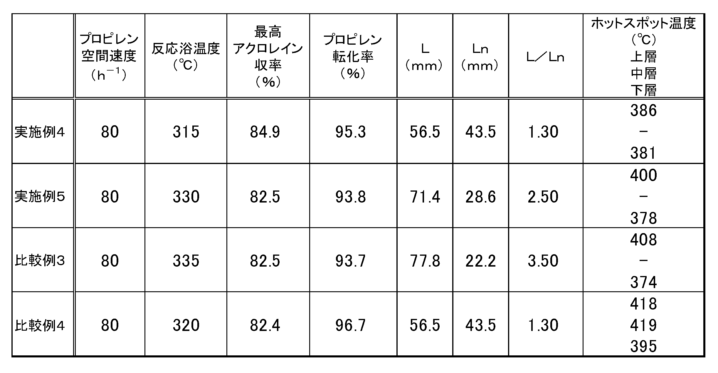
表3の結果より、上層と下層で触媒活性成分の組成の異なる触媒層をL/Ln=1.30で充填した実施例4は、最高アクロレイン収率が高く、また反応浴温度も低く抑えられ、更には上層のホットスポット温度を下げることができており、高い収率で長期間安定して酸化反応を行うことができることが確認された。また、同様に上層と下層で触媒活性成分の組成の異なる触媒層をL/Ln=2.50で充填した実施例5は、反応浴温度が低く、かつ上層のホットスポット温度も低く抑えることができている。これに対し、L/Ln=3.50で充填した比較例3は、反応浴温度を上げなければアクロレイン収率を上げることができず、その為上層のホットスポット温度も高くなっている。また上層、中層、下層のすべてで触媒活性成分が同一の組成を有する触媒層を使用した比較例4では、反応浴温度を抑えても非常に高い上層ホットスポット温度を示した。
本発明を特定の態様を参照して詳細に説明したが、本発明の精神と範囲を離れることなく様々な変更および修正が可能であることは、当業者にとって明らかである。
なお、本願は、2019年3月29日付で出願された日本国特許出願(特願2019-065494)に基づいており、その全体が引用により援用される。また、ここに引用されるすべての参照は全体として取り込まれる。
なお、本願は、2019年3月29日付で出願された日本国特許出願(特願2019-065494)に基づいており、その全体が引用により援用される。また、ここに引用されるすべての参照は全体として取り込まれる。
本願発明によって、不飽和アルデヒド製造プラントにおける収率改善と反応暴走抑制効果を実現することができる。これにより長期にわたり、工業プラントで安定した収率とともに安定した運転が可能となる。
Claims (7)
- 固定床多管型反応器を用いて、アルケンを部分酸化して対応する不飽和アルデヒドを製造する不飽和アルデヒドの製造方法であって、
反応管のガス流れ方向に対しn分割(nは2以上)して形成される複数の触媒層を設け、
反応管ガス入口側から数えてn-1層目までの触媒層の充填長をL、反応管ガス入口側から数えてn層目の触媒層の充填長をLnとしたとき、L及びLnの関係が下記式(1)を満たし、
1<L/Ln≦3 (1)
反応管ガス入口側から数えてn-1層目までの触媒層に含まれる触媒活性成分の組成と、反応管ガス入口側から数えてn層目の触媒層に含まれる触媒活性成分の組成とが異なる、不飽和アルデヒドの製造方法。 - 前記L及びLnの関係が下記式(2)を満たす、請求項1に記載の不飽和アルデヒドの製造方法。
1.1<L/Ln≦1.4 (2)
- 触媒層に含まれる触媒の形状が球状である、請求項1又は2に記載の不飽和アルデヒドの製造方法。
- 原料中のアルケンの濃度が6~12容量%である、請求項1~3のいずれか1項に記載の不飽和アルデヒドの製造方法。
- 反応管中のそれぞれの触媒層が、下記式(3)で表される組成を有する触媒活性成分を含む触媒を含む、請求項1~4のいずれか1項に記載の不飽和アルデヒドの製造方法。
Mo12 Bia Feb Coc Nid Xe Yf Zg Oh (3)
(Xはマグネシウム(Mg)、カルシウム(Ca)、マンガン(Mn)、銅(Cu)、亜鉛(Zn)、セリウム(Ce)及びサマリウム(Sm)からなる群から選ばれる少なくとも1種の元素であり、Yはホウ素(B)、リン(P)、砒素(As)、アンチモン(Sb)及びタングステン(W)からなる群から選ばれる少なくとも1種の元素であり、Zはナトリウム(Na)、カリウム(K)、ルビジウム(Rb)及びセシウム(Cs)からなる群より選ばれる少なくとも1種の元素であり、(a)から(g)は各成分の原子比率を表し、hは触媒成分の酸化度で決定される数値を表し、a=0.40~2.0、b=1~3、c=3~7.5、d=2~4、e=0~10、f=0~10、g=0.01~0.50、hは他の元素の酸化状態を満足させる数値で表記され、d/aが1以上9以下であり、かつd/gが5以上350以下であり、かつa/gが0.8以上90以下である。) - n層目の触媒層に含まれる触媒が不活性物質で希釈されていない触媒である、請求項1~5のいずれか一項に記載の不飽和アルデヒドの製造方法。
- 触媒層に含まれる触媒が担持触媒である、請求項1~6のいずれか一項に記載の不飽和アルデヒドの製造方法。
Priority Applications (5)
| Application Number | Priority Date | Filing Date | Title |
|---|---|---|---|
| CN202080021146.8A CN113573811B (zh) | 2019-03-29 | 2020-03-17 | 不饱和醛的制造方法 |
| SG11202109109YA SG11202109109YA (en) | 2019-03-29 | 2020-03-17 | Method for producing unsaturated aldehyde |
| JP2020549710A JP6912153B2 (ja) | 2019-03-29 | 2020-03-17 | 不飽和アルデヒドの製造方法 |
| EP20783026.6A EP3950128A4 (en) | 2019-03-29 | 2020-03-17 | Method for producing unsaturated aldehyde |
| US17/437,250 US12157720B2 (en) | 2019-03-29 | 2020-03-17 | Method for producing unsaturated aldehyde |
Applications Claiming Priority (2)
| Application Number | Priority Date | Filing Date | Title |
|---|---|---|---|
| JP2019065494 | 2019-03-29 | ||
| JP2019-065494 | 2019-03-29 |
Publications (1)
| Publication Number | Publication Date |
|---|---|
| WO2020203266A1 true WO2020203266A1 (ja) | 2020-10-08 |
Family
ID=72668595
Family Applications (1)
| Application Number | Title | Priority Date | Filing Date |
|---|---|---|---|
| PCT/JP2020/011774 Ceased WO2020203266A1 (ja) | 2019-03-29 | 2020-03-17 | 不飽和アルデヒドの製造方法 |
Country Status (6)
| Country | Link |
|---|---|
| US (1) | US12157720B2 (ja) |
| EP (1) | EP3950128A4 (ja) |
| JP (2) | JP6912153B2 (ja) |
| CN (1) | CN113573811B (ja) |
| SG (1) | SG11202109109YA (ja) |
| WO (1) | WO2020203266A1 (ja) |
Cited By (3)
| Publication number | Priority date | Publication date | Assignee | Title |
|---|---|---|---|---|
| WO2023048284A1 (ja) * | 2021-09-27 | 2023-03-30 | 日本化薬株式会社 | 多管式反応器の運転またはその準備行為をサポートする方法 |
| JPWO2024080203A1 (ja) * | 2022-10-12 | 2024-04-18 | ||
| WO2024080208A1 (ja) * | 2022-10-12 | 2024-04-18 | 日本化薬株式会社 | 不飽和アルデヒドの製造方法および不飽和アルデヒドの製造装置 |
Citations (15)
| Publication number | Priority date | Publication date | Assignee | Title |
|---|---|---|---|---|
| JPH083093A (ja) | 1994-06-20 | 1996-01-09 | Sumitomo Chem Co Ltd | アクロレインおよびアクリル酸の製造方法 |
| JPH0892147A (ja) * | 1994-09-08 | 1996-04-09 | Basf Ag | アクロレインへのプロペンの接触気相酸化方法 |
| JPH10168003A (ja) | 1996-12-03 | 1998-06-23 | Nippon Kayaku Co Ltd | アクロレイン及びアクリル酸の製造方法 |
| JP2001226302A (ja) | 2000-02-16 | 2001-08-21 | Nippon Shokubai Co Ltd | アクロレインおよびアクリル酸の製造方法 |
| JP2001328951A (ja) | 2000-05-19 | 2001-11-27 | Nippon Shokubai Co Ltd | 不飽和アルデヒドおよび不飽和カルボン酸の製造方法 |
| JP2003146920A (ja) | 2001-11-07 | 2003-05-21 | Mitsubishi Chemicals Corp | アクロレインおよびアクリル酸の製造方法 |
| JP2003164763A (ja) | 2001-12-03 | 2003-06-10 | Mitsubishi Chemicals Corp | プロピレン酸化用複合酸化物触媒の製造方法 |
| JP2004002209A (ja) | 2002-03-29 | 2004-01-08 | Nippon Shokubai Co Ltd | 不飽和アルデヒドの製造方法 |
| JP2005320315A (ja) | 2003-10-22 | 2005-11-17 | Nippon Shokubai Co Ltd | 接触気相酸化反応 |
| JP2008504310A (ja) * | 2004-07-01 | 2008-02-14 | ビーエーエスエフ アクチェンゲゼルシャフト | プロピレンの不均一触媒部分気相酸化によるアクロレイン、アクリル酸、またはその混合物の製造方法 |
| JP2012176938A (ja) * | 2011-02-02 | 2012-09-13 | Nippon Kayaku Co Ltd | 不飽和アルデヒドおよび/または不飽和カルボン酸の製造方法 |
| WO2014181839A1 (ja) | 2013-05-09 | 2014-11-13 | 日本化薬株式会社 | 不飽和アルデヒドおよび/または不飽和カルボン酸製造用触媒、その製造方法及び不飽和アルデヒドおよび/または不飽和カルボン酸の製造方法 |
| WO2016136882A1 (ja) | 2015-02-27 | 2016-09-01 | 日本化薬株式会社 | 不飽和アルデヒドおよび/または不飽和カルボン酸製造用触媒及びその製造方法並びに不飽和アルデヒドおよび/または不飽和カルボン酸の製造方法 |
| WO2017010159A1 (ja) * | 2015-07-10 | 2017-01-19 | 日本化薬株式会社 | 不飽和アルデヒドおよび/または不飽和カルボン酸の製造方法 |
| JP2019065494A (ja) | 2017-09-29 | 2019-04-25 | 株式会社Lixil | 建具 |
Family Cites Families (14)
| Publication number | Priority date | Publication date | Assignee | Title |
|---|---|---|---|---|
| JP4426069B2 (ja) * | 2000-06-12 | 2010-03-03 | 株式会社日本触媒 | アクリル酸の製造方法 |
| US6960684B2 (en) | 2002-03-29 | 2005-11-01 | Nippon Shokubai Co., Ltd. | Production process for unsaturated aldehyde |
| US7045657B2 (en) | 2002-04-03 | 2006-05-16 | Nippon Shokubai Co., Ltd. | Catalytic gas phase oxidation process |
| US7161044B2 (en) | 2003-10-22 | 2007-01-09 | Nippon Shokubai Co., Ltd. | Catalytic gas phase oxidation reaction |
| CN1697794A (zh) | 2003-12-03 | 2005-11-16 | 三菱化学株式会社 | 不饱和醛及不饱和羧酸的制备方法 |
| US7592483B2 (en) | 2004-07-01 | 2009-09-22 | Basf Aktiengesellschaft | Preparation of acrolein or acrylic acid or a mixture thereof by heterogeneously catalyzed partial gas phase oxidation of propylene |
| JP5156375B2 (ja) * | 2004-07-01 | 2013-03-06 | ビーエーエスエフ ソシエタス・ヨーロピア | プロパンからのアクロレインもしくはアクリル酸またはそれらの混合物の製造 |
| BRPI0906766A2 (pt) | 2008-01-17 | 2015-07-14 | Lg Chemical Ltd | Sistema do catalisador, reator de oxidação contendo o mesmo, e método de preparação para acroleíne e ácido acrílico empregando o mesmo |
| US8673245B2 (en) | 2008-09-22 | 2014-03-18 | Nippon Shokubai Co., Ltd. | Fixed-bed reactor and process for producing acrylic acid using the reactor |
| DE102009041960A1 (de) | 2009-09-17 | 2011-04-07 | Süd-Chemie AG | Verfahren zur Herstellung einer Katalysatoranordnung für die Herstellung von Phthalsäureanhydrid |
| CN103772172B (zh) | 2012-10-23 | 2016-02-10 | 中国石油天然气股份有限公司 | 一种丙烯选择性氧化生产丙烯醛的方法 |
| RU2654063C2 (ru) | 2013-07-18 | 2018-05-16 | Ниппон Каяку Кабусики Кайся | Способ получения ненасыщенного альдегида и/или ненасыщенной карбоновой кислоты |
| WO2016017722A1 (ja) * | 2014-08-01 | 2016-02-04 | 株式会社日本触媒 | 不活性物質の回収方法及び当該方法により回収された不活性物質を用いたアクリル酸の製造方法 |
| CN105801394B (zh) | 2014-12-31 | 2018-10-02 | 上海华谊新材料有限公司 | 由叔丁醇制备甲基丙烯醛的方法 |
-
2020
- 2020-03-17 WO PCT/JP2020/011774 patent/WO2020203266A1/ja not_active Ceased
- 2020-03-17 SG SG11202109109YA patent/SG11202109109YA/en unknown
- 2020-03-17 JP JP2020549710A patent/JP6912153B2/ja active Active
- 2020-03-17 EP EP20783026.6A patent/EP3950128A4/en active Pending
- 2020-03-17 CN CN202080021146.8A patent/CN113573811B/zh active Active
- 2020-03-17 US US17/437,250 patent/US12157720B2/en active Active
-
2021
- 2021-06-18 JP JP2021101329A patent/JP7506031B2/ja active Active
Patent Citations (15)
| Publication number | Priority date | Publication date | Assignee | Title |
|---|---|---|---|---|
| JPH083093A (ja) | 1994-06-20 | 1996-01-09 | Sumitomo Chem Co Ltd | アクロレインおよびアクリル酸の製造方法 |
| JPH0892147A (ja) * | 1994-09-08 | 1996-04-09 | Basf Ag | アクロレインへのプロペンの接触気相酸化方法 |
| JPH10168003A (ja) | 1996-12-03 | 1998-06-23 | Nippon Kayaku Co Ltd | アクロレイン及びアクリル酸の製造方法 |
| JP2001226302A (ja) | 2000-02-16 | 2001-08-21 | Nippon Shokubai Co Ltd | アクロレインおよびアクリル酸の製造方法 |
| JP2001328951A (ja) | 2000-05-19 | 2001-11-27 | Nippon Shokubai Co Ltd | 不飽和アルデヒドおよび不飽和カルボン酸の製造方法 |
| JP2003146920A (ja) | 2001-11-07 | 2003-05-21 | Mitsubishi Chemicals Corp | アクロレインおよびアクリル酸の製造方法 |
| JP2003164763A (ja) | 2001-12-03 | 2003-06-10 | Mitsubishi Chemicals Corp | プロピレン酸化用複合酸化物触媒の製造方法 |
| JP2004002209A (ja) | 2002-03-29 | 2004-01-08 | Nippon Shokubai Co Ltd | 不飽和アルデヒドの製造方法 |
| JP2005320315A (ja) | 2003-10-22 | 2005-11-17 | Nippon Shokubai Co Ltd | 接触気相酸化反応 |
| JP2008504310A (ja) * | 2004-07-01 | 2008-02-14 | ビーエーエスエフ アクチェンゲゼルシャフト | プロピレンの不均一触媒部分気相酸化によるアクロレイン、アクリル酸、またはその混合物の製造方法 |
| JP2012176938A (ja) * | 2011-02-02 | 2012-09-13 | Nippon Kayaku Co Ltd | 不飽和アルデヒドおよび/または不飽和カルボン酸の製造方法 |
| WO2014181839A1 (ja) | 2013-05-09 | 2014-11-13 | 日本化薬株式会社 | 不飽和アルデヒドおよび/または不飽和カルボン酸製造用触媒、その製造方法及び不飽和アルデヒドおよび/または不飽和カルボン酸の製造方法 |
| WO2016136882A1 (ja) | 2015-02-27 | 2016-09-01 | 日本化薬株式会社 | 不飽和アルデヒドおよび/または不飽和カルボン酸製造用触媒及びその製造方法並びに不飽和アルデヒドおよび/または不飽和カルボン酸の製造方法 |
| WO2017010159A1 (ja) * | 2015-07-10 | 2017-01-19 | 日本化薬株式会社 | 不飽和アルデヒドおよび/または不飽和カルボン酸の製造方法 |
| JP2019065494A (ja) | 2017-09-29 | 2019-04-25 | 株式会社Lixil | 建具 |
Non-Patent Citations (1)
| Title |
|---|
| See also references of EP3950128A4 |
Cited By (9)
| Publication number | Priority date | Publication date | Assignee | Title |
|---|---|---|---|---|
| WO2023048284A1 (ja) * | 2021-09-27 | 2023-03-30 | 日本化薬株式会社 | 多管式反応器の運転またはその準備行為をサポートする方法 |
| JPWO2023048284A1 (ja) * | 2021-09-27 | 2023-03-30 | ||
| JP7345072B2 (ja) | 2021-09-27 | 2023-09-14 | 日本化薬株式会社 | 多管式反応器の運転またはその準備行為をサポートする方法 |
| JPWO2024080203A1 (ja) * | 2022-10-12 | 2024-04-18 | ||
| WO2024080203A1 (ja) * | 2022-10-12 | 2024-04-18 | 日本化薬株式会社 | 不飽和アルデヒドの製造方法および不飽和アルデヒドの製造装置 |
| WO2024080208A1 (ja) * | 2022-10-12 | 2024-04-18 | 日本化薬株式会社 | 不飽和アルデヒドの製造方法および不飽和アルデヒドの製造装置 |
| JPWO2024080208A1 (ja) * | 2022-10-12 | 2024-04-18 | ||
| JP7551026B2 (ja) | 2022-10-12 | 2024-09-13 | 日本化薬株式会社 | 不飽和アルデヒドの製造方法および不飽和アルデヒドの製造装置 |
| JP7551027B2 (ja) | 2022-10-12 | 2024-09-13 | 日本化薬株式会社 | 不飽和アルデヒドの製造方法および不飽和アルデヒドの製造装置 |
Also Published As
| Publication number | Publication date |
|---|---|
| US12157720B2 (en) | 2024-12-03 |
| US20220169587A1 (en) | 2022-06-02 |
| JP7506031B2 (ja) | 2024-06-25 |
| EP3950128A1 (en) | 2022-02-09 |
| JP6912153B2 (ja) | 2021-07-28 |
| JPWO2020203266A1 (ja) | 2021-04-30 |
| EP3950128A4 (en) | 2023-01-04 |
| CN113573811A (zh) | 2021-10-29 |
| JP2021152049A (ja) | 2021-09-30 |
| SG11202109109YA (en) | 2021-11-29 |
| CN113573811B (zh) | 2023-12-08 |
Similar Documents
| Publication | Publication Date | Title |
|---|---|---|
| JP6294883B2 (ja) | 不飽和アルデヒドおよび/または不飽和カルボン酸の製造方法 | |
| JP6199972B2 (ja) | 不飽和アルデヒドおよび/または不飽和カルボン酸の製造方法 | |
| JP2018140993A (ja) | 不飽和アルデヒドおよび/または不飽和カルボン酸の製造方法 | |
| KR102612311B1 (ko) | 아크롤레인, 메타크롤레인, 아크릴산, 또는 메타크릴산의 제조 방법 | |
| JP6831920B2 (ja) | 不飽和アルデヒド及び不飽和カルボン酸の少なくとも一方の製造方法並びに不飽和アルデヒド及び不飽和カルボン酸の少なくとも一方の製造用触媒 | |
| WO2016136882A1 (ja) | 不飽和アルデヒドおよび/または不飽和カルボン酸製造用触媒及びその製造方法並びに不飽和アルデヒドおよび/または不飽和カルボン酸の製造方法 | |
| JPWO2014181839A1 (ja) | 不飽和アルデヒドおよび/または不飽和カルボン酸製造用触媒、その製造方法及び不飽和アルデヒドおよび/または不飽和カルボン酸の製造方法 | |
| JP7506031B2 (ja) | 不飽和アルデヒドの製造方法 | |
| JP2022124634A (ja) | イソプレン製造用触媒及びその用途 | |
| JP7817036B2 (ja) | 不飽和アルデヒド及び/又は不飽和カルボン酸の製造方法 | |
| JP7551027B2 (ja) | 不飽和アルデヒドの製造方法および不飽和アルデヒドの製造装置 | |
| JP7551026B2 (ja) | 不飽和アルデヒドの製造方法および不飽和アルデヒドの製造装置 | |
| JP6238354B2 (ja) | 不飽和アルデヒドおよび/または不飽和カルボン酸製造用触媒およびその製造方法ならびに不飽和アルデヒドおよび/または不飽和カルボン酸の製造方法 | |
| JP2025153075A (ja) | メタクロレイン及び/又はメタクリル酸の製造用触媒 | |
| WO2025100265A1 (ja) | 不飽和アルデヒドまたは不飽和カルボン酸の製造方法 |
Legal Events
| Date | Code | Title | Description |
|---|---|---|---|
| ENP | Entry into the national phase |
Ref document number: 2020549710 Country of ref document: JP Kind code of ref document: A |
|
| 121 | Ep: the epo has been informed by wipo that ep was designated in this application |
Ref document number: 20783026 Country of ref document: EP Kind code of ref document: A1 |
|
| NENP | Non-entry into the national phase |
Ref country code: DE |
|
| ENP | Entry into the national phase |
Ref document number: 2020783026 Country of ref document: EP Effective date: 20211029 |