WO2020203623A1 - 空気調和機の室内ユニット、および空気調和機の室内ユニットの設置方法 - Google Patents
空気調和機の室内ユニット、および空気調和機の室内ユニットの設置方法 Download PDFInfo
- Publication number
- WO2020203623A1 WO2020203623A1 PCT/JP2020/013593 JP2020013593W WO2020203623A1 WO 2020203623 A1 WO2020203623 A1 WO 2020203623A1 JP 2020013593 W JP2020013593 W JP 2020013593W WO 2020203623 A1 WO2020203623 A1 WO 2020203623A1
- Authority
- WO
- WIPO (PCT)
- Prior art keywords
- indoor unit
- housing
- propeller fan
- air
- air conditioner
- Prior art date
- Legal status (The legal status is an assumption and is not a legal conclusion. Google has not performed a legal analysis and makes no representation as to the accuracy of the status listed.)
- Ceased
Links
Images

Classifications
-
- F—MECHANICAL ENGINEERING; LIGHTING; HEATING; WEAPONS; BLASTING
- F24—HEATING; RANGES; VENTILATING
- F24F—AIR-CONDITIONING; AIR-HUMIDIFICATION; VENTILATION; USE OF AIR CURRENTS FOR SCREENING
- F24F1/00—Room units for air-conditioning, e.g. separate or self-contained units or units receiving primary air from a central station
- F24F1/0007—Indoor units, e.g. fan coil units
- F24F1/0018—Indoor units, e.g. fan coil units characterised by fans
- F24F1/0029—Axial fans
-
- F—MECHANICAL ENGINEERING; LIGHTING; HEATING; WEAPONS; BLASTING
- F24—HEATING; RANGES; VENTILATING
- F24F—AIR-CONDITIONING; AIR-HUMIDIFICATION; VENTILATION; USE OF AIR CURRENTS FOR SCREENING
- F24F1/00—Room units for air-conditioning, e.g. separate or self-contained units or units receiving primary air from a central station
- F24F1/0007—Indoor units, e.g. fan coil units
- F24F1/0043—Indoor units, e.g. fan coil units characterised by mounting arrangements
- F24F1/0047—Indoor units, e.g. fan coil units characterised by mounting arrangements mounted in the ceiling or at the ceiling
-
- F—MECHANICAL ENGINEERING; LIGHTING; HEATING; WEAPONS; BLASTING
- F24—HEATING; RANGES; VENTILATING
- F24F—AIR-CONDITIONING; AIR-HUMIDIFICATION; VENTILATION; USE OF AIR CURRENTS FOR SCREENING
- F24F13/00—Details common to, or for air-conditioning, air-humidification, ventilation or use of air currents for screening
- F24F13/08—Air-flow control members, e.g. louvres, grilles, flaps or guide plates
- F24F13/082—Grilles, registers or guards
-
- F—MECHANICAL ENGINEERING; LIGHTING; HEATING; WEAPONS; BLASTING
- F24—HEATING; RANGES; VENTILATING
- F24F—AIR-CONDITIONING; AIR-HUMIDIFICATION; VENTILATION; USE OF AIR CURRENTS FOR SCREENING
- F24F13/00—Details common to, or for air-conditioning, air-humidification, ventilation or use of air currents for screening
- F24F13/20—Casings or covers
Definitions
- An embodiment of the present invention relates to an indoor unit of an air conditioner and a method of installing an indoor unit of an air conditioner.
- This type of outdoor unit includes a casing, a fan, and a heat exchanger.
- the casing has a suction port provided on the side surface and an air outlet provided on the bottom surface.
- the fan is located in the casing to create an air flow from the inlet to the outlet.
- the heat exchanger is arranged in the casing and between the fan and the suction port.
- the conventional indoor unit is installed in the space behind the ceiling. That is, the conventional indoor unit is buried in a place sufficiently separated from the floor surface of the installation place in the height direction, that is, in the ceiling.
- the conventional indoor unit is equipped with an air outlet having a plurality of round cone-shaped blades, a so-called anemostat. This type of outlet obstructs the view from directly below. Therefore, in the conventional indoor unit, it is difficult to directly see the fan in the casing from below the air outlet.
- the indoor unit that is hung from the ceiling of the installation location is closer to the floor than the indoor unit that is buried in the ceiling like the conventional indoor unit.
- the present invention is provided with a fan guard that can be installed while being suspended from the ceiling and can easily see the rotating fan in the casing, while agitating unnecessary fear by the rotating fan. It is an object of the present invention to provide a method of installing an indoor unit of an air conditioner and an indoor unit of an air conditioner that can foster a sense of security.
- the indoor unit of the air exchanger has a suction port on the side surface and an air outlet on the bottom surface, and has a housing that can be suspended from a structure at the installation location and the housing.
- a heat exchanger provided inside the body, facing the suction port, and arranged in an annular shape when viewed from the bottom of the housing, a rotating shaft extending in the vertical direction of the housing, and a circumferential direction of the rotating shaft. It has a plurality of blades arranged radially in the above, and is surrounded by the heat exchanger in the bottom view of the housing, sucks air from the suction port, and heat-exchanged air by the heat exchanger.
- Rotation of the propeller fan in a virtual plane provided with a propeller fan for blowing out from the outlet toward the lower side of the housing and a fan guard provided at the outlet and orthogonal to the axial direction of the rotation axis.
- the area of the projection area of the movement range of the plurality of blades is the first projection area
- the projection area of the opening portion of the fan guard is the second projection area in the virtual plane and inside the projection area.
- the opening ratio obtained by dividing the second projected area by the first projected area is more than half and substantially uniform in the rotation direction of the propeller fan, and the propeller fan has a low-brightness appearance.
- the brightness of the propeller fan of the indoor unit of the air conditioner according to the embodiment of the present invention is preferably Munsell brightness of 5 or less.
- the saturation of the propeller fan of the indoor unit of the air conditioner according to the embodiment of the present invention is preferably Munsell saturation 4 or less.
- the color of the portion that can be seen from below the indoor unit of the air conditioner according to the embodiment of the present invention is substantially the same as the color of the propeller fan.
- the heat exchanger of the indoor unit of the air conditioner according to the embodiment of the present invention preferably has a black or blue appearance.
- the indoor unit of the air conditioner according to the embodiment of the present invention is provided with a heat insulating material provided on at least one of the top surface of the housing and the opening edge of the air outlet and having a black or gray appearance. It is preferable to have it.
- the brightness of the appearance of the indoor unit of the air conditioner according to the embodiment of the present invention is higher than the brightness of the propeller fan.
- the indoor unit of the air conditioner is installed above the lighting device at the installation location.
- the present invention while being provided with a fan guard that can be installed while being suspended from the ceiling and can easily see the rotating fan in the casing, it arouses unnecessary fear by the rotating fan. It is possible to provide a method of installing an indoor unit of an air conditioner and an indoor unit of an air conditioner that can foster a sense of security.
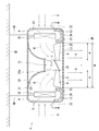
- FIG. 2 is a schematic cross-sectional view of an indoor unit according to an embodiment of the present invention in lines III-III of FIG.
- FIGS. 1 to 3 An embodiment of an indoor unit of the air conditioner and a method of installing the indoor unit of the air conditioner according to the present invention will be described with reference to FIGS. 1 to 3.
- the same or corresponding configurations are designated by the same reference numerals.
- FIG. 1 is a diagram showing an installation location where an indoor unit according to an embodiment of the present invention is provided.
- the air conditioner includes an outdoor unit (not shown) installed outdoors and an indoor unit 1 installed indoors.
- the outdoor unit and the indoor unit 1 are connected via a refrigerant pipe RP that circulates a refrigerant.
- the refrigeration cycle of the air conditioner circulates the refrigerant between the outdoor unit and the indoor unit 1.
- the indoor unit 1 harmonizes the air inside the room, that is, at the installation location.
- the installation location is surrounded by floor FL, wall WA, and ceiling SE.
- the indoor unit 1 is suspended from a structure at the installation site, specifically, a ceiling SE or a beam (not shown).
- a metal rod-shaped hanging member HB extending in the direction of the floor surface is provided on the ceiling SE of the installation location.
- the indoor unit 1 is suspended from the ceiling SE via the suspension member HB. That is, the indoor unit 1 is provided at a position lower than the ceiling SE.
- the indoor unit 1 is a bare type unit in which the housing 5 is separated from the ceiling SE and arranged in a bare state in the room without being embedded in the ceiling SE.
- the indoor unit 1 is installed above the pendant light PL of the installation location. More precisely, the indoor unit 1 is installed with the lower surface of the indoor unit 1, that is, the surface of the air outlet 25 of the indoor unit 1, which will be described later, positioned above the light source of the pendant light PL. In this case, the indoor unit 1 may be installed above the pendant light PL by moving the fixing portion between the hanging member HB and the indoor unit 1 up and down, or the installation height of the indoor unit 1 is determined in advance and then. The installation height of the pendant light PL, that is, the hanging position may be adjusted.
- the indoor unit 1 includes a cylindrical or disk-shaped housing 5 having a circular top surface and a circular bottom surface, and a housing 5
- a heat exchanger 6 provided inside the housing 5 and arranged in an annular shape when viewed from the bottom of the housing 5, a fan motor 11 having a rotating shaft 7 extending in the vertical direction at substantially the center of the housing 5, and a rotating shaft 7.
- a propeller fan 9 having a plurality of blades 8 arranged radially in the circumferential direction and surrounded by the heat exchanger 6 when viewed from the bottom of the housing 5, and a heat exchanger 6 provided below the heat exchanger 6. It is provided with a drain pan 12 that receives dew condensation water generated on the surface of the surface of the vehicle, and a fan guard 13 that protects the propeller fan 9.
- the indoor unit 1 is provided with an electric expansion valve (not shown) which is an expansion device for the refrigeration cycle.
- the housing 5 includes a top plate 21 that closes the top surface.
- the upper surface plate 21 is fixed to the hanging member HB embedded and fixed in the ceiling SE.
- a side plate 23 having a suction port 22 for sucking air K from the periphery of the indoor unit 1 is provided on the outer peripheral surface of the housing 5, that is, the side surface of the housing 5.
- Each suction port 22 is opened in the shape of a curved rectangular window.
- the bottom surface of the housing 5 has an outlet 25 for blowing out air K downward, and a substantially circular bottom plate 26 is provided.
- the air outlet 25 is arranged at the center of the bottom surface of the housing 5.
- the air outlet 25 has a circular shape when viewed from the bottom of the housing 5.
- a fan guard 13 is provided at the air outlet 25.
- Each of the upper surface plate 21 of the housing 5 and the lower surface plate 26 of the housing 5 is fixed and integrated with a side plate 23 as a frame body of the suction port 22 by a fastening member, for example, a screw (not shown).
- the boundary portion between the top surface and the side surface of the housing 5 and the boundary portion between the bottom surface and the side surface of the housing 5 have an arc shape with no corners.
- the boundary portion between the top surface and the side surface of the housing 5 and the boundary portion between the bottom surface and the side surface of the housing 5 have so-called corners R (rounded corners).
- the indoor unit 1 includes a cylindrical housing 5 having a corner R or a disk-shaped housing 5 having a corner R. Therefore, the indoor unit 1 can have a higher design than the conventional ceiling-embedded indoor unit having a rectangular housing. Further, since the indoor unit 1 has no corners in the housing 5, even if it is exposed indoors, it does not give a feeling of oppression to a person below the indoor unit 1.
- the housing 5 may have a polygonal prism shape or a polygonal disc shape.
- the shape of the top surface and the bottom surface of the housing 5 may be a polygonal shape of a pentagon or more.
- the housing 5 may be of a regular polygonal prism shape or a regular polygonal disc shape. That is, the shapes of the top surface and the bottom surface of the housing 5 may be a regular polygon.
- the indoor unit 1 sucks the indoor air K from the suction port 22 on the side surface of the housing 5 and blows it out from the air outlet 25 on the bottom surface of the housing 5. That is, the indoor unit 1 can flow the air K flowing along the vicinity of the ceiling SE toward the floor FL.
- the air K that has reached the floor FL from the indoor unit 1 flows along the wall WA, returns to the vicinity of the ceiling SE again, and is circulated by the indoor unit 1. Therefore, the indoor unit 1 can efficiently circulate the indoor air K.
- the indoor unit 1 is preferably provided in the central portion of the installation location to be air-conditioned.
- the indoor unit 1 may be installed at the installation location with the top surface of the housing 5, that is, the top plate 21 close to the ceiling SE. For example, when the ceiling SE is low and the indoor unit 1 is suspended from the ceiling SE, the comfortability is hindered. Therefore, it is preferable to install the indoor unit 1 close to the ceiling SE.
- a mounting base 28 for the fan motor 11 is provided on the inside of the housing 5 and on the lower surface of the upper surface plate 21.
- the mounting base 28 has, for example, a frustum shape that narrows as it moves away from the top plate 21, in other words, as it goes downward.
- the mounting base 28 has a side surface 28a that is recessed and curved toward the center side of the cone in a side view.
- the protruding end face of the mounting base 28, that is, the bottom surface having the smaller diameter, is located substantially in the center of the housing 5.
- a fan motor 11 is fixed to the lower surface of the lower bottom surface of the mounting base 28.
- the heat exchanger 6 is fixed to the upper surface plate 21 of the housing 5 via the fixing member 31.
- the heat exchangers 6 are arranged in an annular shape when viewed from the bottom of the housing 5.
- the heat exchanger 6 has a rectangular shape that is long in the vertical direction of the housing 5 in a vertical cross-sectional view.
- the outer peripheral surface of the heat exchanger 6 faces the suction port 22.
- the inner peripheral surface of the heat exchanger 6 faces the curved side surface 28a of the mounting base 28 of the fan motor 11.
- the shortest distance connecting the circumference drawn by the rotation locus of the blade 8 of the propeller fan 9 and the heat exchanger 6 is set to be substantially the same over the entire circumference of the propeller fan 9.
- the propeller fan 9 is arranged so that the air blown by the propeller fan 9 is uniform throughout the heat exchanger 6.
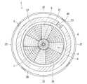
- the heat exchanger 6 is a molded product obtained by bending a flat plate-shaped heat exchanger in which a refrigerant pipe penetrates a large number of aligned aluminum fins in an annular shape. As shown in FIG. 3, the gap between both ends of the heat exchanger 6 bent in an annular shape is closed by a closing plate 40 for blocking the flow of air before and after the heat exchange.
- the propeller fan 9 is rotationally driven by the fan motor 11.
- the rotating propeller fan 9 sucks the air K around the housing 5 from the suction port 22, and blows out the air K heat-exchanged by the heat exchanger 6 from the air outlet 25 toward the lower side of the housing 5.
- the center of the annular heat exchanger 6, the center of rotation of the propeller fan 9, and the center of the circular air outlet 25 are aligned.
- the diameter D of the propeller fan 9 is slightly smaller than the diameter of the outlet 25.
- the propeller fan 9 includes a hub 32 fixed to the rotating shaft 7 and a plurality of blades 8 integrated with the hub 32.
- the rotating shaft 7 extends in the vertical direction with the indoor unit 1 installed as shown in FIG.
- the flow of air K sucked from the suction port 22 toward the center of the housing 5 by the rotational drive of the propeller fan 9 is smoothly guided and blown downward by the curved side surface 28a of the mounting base 28. Head to Exit 25.
- the mounting base 28 improves the structural strength of supporting the fan motor 11 while improving the ventilation characteristics of the propeller fan 9.
- the drain pan 12 is a heat insulating material having a water receiving portion.
- the drain pan 12 is placed on the lower surface plate 26 of the housing 5 and integrated with the lower surface plate 26. That is, the number of parts of the indoor unit 1 can be reduced and the manufacturing cost can be reduced as compared with the case where the drain pan 12 is held by another member.
- the drain pan 12 is arranged directly below the heat exchanger 6. During the cooling operation in which the heat exchanger 6 functions as an evaporator, the moisture contained in the air K passing through the heat exchanger 6, that is, the moisture in the room condenses on the surface of the heat exchanger 6, and the heat exchanger 6 serves as condensed water. Adheres to and drips from the heat exchanger 6. The drain pan 12 receives the condensed water that falls from the heat exchanger 6.
- the drain pan 12 has a substantially U-shape or a substantially C-shape in a vertical cross-sectional view.
- the annular drain pan 12 in the bottom view of the housing 5 surrounds the propeller fan 9.
- the drain pan 12 extends from directly below the heat exchanger 6 to the edge of the outlet 25. That is, the drain pan 12 extends to the edge of the air outlet 25 close to the outer edge of the propeller fan 9.
- the gap between the outer edge of the propeller fan 9 and the edge of the air outlet 25 is narrow, so that the drain pan 12 can prevent the condensed water from falling or dripping through this gap.
- the condensed water stored in the drain pan 12 is pumped by a drain pump (not shown) provided in the housing 5 and drained to the outside of the indoor unit 1 through a drain pipe (not shown).
- the fan guard 13 is provided at the outlet 25.
- the fan guard 13 is arranged on the leeward side of the propeller fan 9.
- the fan guard 13 is provided for safety so that the propeller fan 9 is not touched by people or objects.
- the fan guard 13 is a grid in which polygons are closely arranged, or a grid in which the propeller fans 9 are evenly arranged in the rotation direction, that is, in the circumferential direction.
- the fan guard 13 is a grid for orderly aligning small openings of regular polygons such as an equilateral triangle, a square, and a regular pentagon, and a grid for orderly aligning small openings of a fan shape.
- the compressor of the outdoor unit discharges high-temperature and high-pressure gas refrigerant and sends it to the outdoor heat exchanger, that is, the condenser.
- the outdoor heat exchanger exchanges heat between the refrigerant flowing inside and the outdoor air to condense the refrigerant.
- the condensed liquid refrigerant is sent to the indoor unit 1 through the refrigerant pipe RP.
- the indoor unit 1 expands the liquid refrigerant flowing from the refrigerant pipe RP with an electric expansion valve, and sends the low-temperature gas-liquid mixed refrigerant to the heat exchanger 6, that is, the evaporator.
- the heat exchanger 6 exchanges heat between the low-temperature refrigerant flowing inside the heat exchanger 6 and the air in the room to gasify the refrigerant. At this time, the room is cooled by the low-temperature air K blown out from the room unit 1.
- the compressor of the outdoor unit discharges high-temperature and high-pressure gas refrigerant and sends it to the heat exchanger 6 of the indoor unit 1, that is, the condenser.
- the heat exchanger 6 exchanges heat between the refrigerant flowing inside the heat exchanger 6 and the air K in the room to condense the refrigerant.
- the room is heated by the high temperature air K blown out from the room unit 1.
- a virtual plane VP orthogonal to the extending direction of the rotating shaft 7, that is, the axial direction of the rotating shaft 7, that is, the vertical direction in the installed state of the indoor unit 1 is set (FIG. 2).
- the projection region A has an annular shape in which the base of each blade 8, that is, the boundary portion between the hub 32 and the blade 8 is the inner circumference, and the tip of each blade 8 is the outer circumference.
- the projection area A is an annular area in which the locus of movement of each blade 8 is projected onto the virtual plane VP.
- the first projected area S1 is the area of the annular projection region A.
- the hub 32 portion does not contribute to the blowing work of the propeller fan 9, so that the projected area of the hub 32 portion, that is, the area inside the inner circumference of the projection area A is the first projected area. Excluded from S1. That is, in the portion inside the inner circumference of the projection region A corresponding to the hub 32, even if the air outlet 25 is closed, the blowing performance of the propeller fan 9 is not affected.
- the projected area of the opening portion of the fan guard 13 inside the virtual plane VP and the projection area A is defined as the second projected area S2.
- the grid-like fan guard 13 has a large number of small openings.
- the second projected area S2 corresponds to the total opening area of a large number of small openings in the projected area A when viewed from the axial direction of the rotating shaft 7.
- the second projected area S2 is equal to the area obtained by subtracting the projected area of the grid in the projected area A from the area of the projected area A when viewed from the axial direction of the rotation axis 7.
- the aperture ratio AR of the fan guard 13 obtained by dividing the second projected area S2 by the first projected area S1 is more than half. That is, the second projected area S2, the first projected area S1, and the aperture ratio AR have the following relationship [Equation 1]. This is intended to improve the ventilation performance of the propeller fan 9 as much as possible.
- a fan guard 13 is required to protect the propeller fan 9.
- the aperture ratio AR is substantially uniform in the rotation direction of the propeller fan 9 and is uniform.
- the aperture ratio AR in each division area is substantially half or more.
- the aperture ratio AR in each divided area is substantially half or more.
- each blade 8 of the propeller fan 9 can be easily rotated from below, that is, from the position of the user through the fan guard 13. It can be visually recognized.
- the propeller fan 9 is driven at a rotation speed of 10 rotations per second (10 rps, revolutions per second, rotations per second) or more in order to obtain sufficient ventilation performance, the plurality of rotating blades 8 may be used. There is a possibility of inciting unnecessary fear to the user looking up at the indoor unit 1 from below.
- the propeller fan 9 has a low-brightness appearance. For example, it has a black appearance.
- the brightness of the propeller fan 9 is preferably Munsell brightness 5 or less.
- the saturation of the propeller fan 9 is preferably Munsell saturation 4 or less.
- the top surface of the housing 5 is closed by the top plate 21.
- the side surface of the housing 5 has a suction port 22, but the light emitted from the suction port 22 into the housing 5 is substantially blocked by the heat exchanger 6 in the housing 5. Therefore, the inside of the housing 5 is dark because the light of the illumination of the installation location is hard to reach. Further, when a filter is provided in the suction port 22 in order to prevent dust from adhering to the heat exchanger 6, the light shining into the housing 5 is further blocked, and the inside of the housing 5 becomes a dark box. Therefore, by lowering the brightness of the propeller fan 9, the visibility of the propeller fan 9 in the housing 5 is significantly reduced. Then, the user looking up at the indoor unit 1 from below cannot see the plurality of rotating blades 8 and does not feel unnecessary fear.
- the portion that can be seen from below is substantially the same color as the propeller fan 9.
- the parts that can be seen from below include, for example, the fan guard 13, the outer surface of the lower surface plate 26 (drain pan 12) of the housing 5, the outer surface of the side plate 23 of the housing 5, the inner surface of the upper surface plate 21 of the housing 5, and the mounting base 28. Includes. By making these parts substantially the same color as the propeller fan 9, for example, black, the difference in brightness between the propeller fan 9 and the other parts becomes extremely small. Then, the visibility of the propeller fan 9 in the housing 5 is further lowered.
- the heat exchanger 6 preferably has a blackish or blueish appearance. By doing so, it is possible to prevent the light that enters the housing 5 from the suction port 22 from being reflected by the heat exchanger 6 and entering the inside of the heat exchanger 6. Then, the visibility of the propeller fan 9 in the housing 5 is further lowered.
- the indoor unit 1 may include a heat insulating material 33 provided on at least one of the top surface of the housing 5, that is, the upper surface (outer surface) of the upper surface plate 21, and the opening edge of the air outlet 25.
- the heat insulating material 33 preferably has a blackish or grayish appearance. Then, the visibility of the propeller fan 9 in the housing 5 is further lowered.
- the indoor unit 1 makes the appearance seen from below, the brightness of the so-called design surface, higher than the brightness of the propeller fan 9.
- the difference in brightness between the two is preferably 4 or more in Munsell brightness.
- the design surface viewed from below includes, for example, the lower surface (outer surface) of the fan guard 13, the lower surface (outer surface) of the lower surface plate 26 of the housing 5, and the outer surface of the side plate 23 of the housing 5.
- the indoor unit 1 has a fan guard 13 that is substantially uniform in the rotation direction of the propeller fan 9 and has an aperture ratio AR of more than half, and an appearance with low brightness. It has a propeller fan 9 and a propeller fan 9. Therefore, the indoor unit 1 is provided with a fan guard 13 having a better visibility than the anemostat provided at the air outlet of the conventional indoor unit, but reduces the visibility of the propeller fan 9 rotating in the housing 5. be able to. That is, the indoor unit 1 can foster a sense of security without inciting unnecessary fear caused by the rotating propeller fan 9.
- the indoor unit 1 is installed above the lighting device at the installation location. That is, the surface of the air outlet 25 of the indoor unit 1 is arranged above the light source of the lighting device. Therefore, in the indoor unit 1, it becomes difficult for the light emitted from the lighting inside the housing 5 to enter the housing 5, the housing 5 itself becomes a shadow, and the visibility of the propeller fan 9 rotating in the housing 5 is lowered. be able to. Further, a user located below the indoor unit 1 sees a light source having a high luminous intensity when looking upward, and the difference in brightness makes it difficult to see the inner surface of the air outlet 25 of the indoor unit 1, and the inside of the housing 5 The visibility of the rotating propeller fan 9 is further reduced.
- the propeller fan 9 that can be installed while being suspended from the ceiling and that rotates in the housing 5 can be easily seen. While equipped with a fan guard 13 that maintains high ventilation performance, it is possible to foster a sense of security without agitating unnecessary fear caused by the rotating propeller fan 9.
Landscapes
- Engineering & Computer Science (AREA)
- Chemical & Material Sciences (AREA)
- Combustion & Propulsion (AREA)
- Mechanical Engineering (AREA)
- General Engineering & Computer Science (AREA)
- Air Filters, Heat-Exchange Apparatuses, And Housings Of Air-Conditioning Units (AREA)
- Air-Conditioning Room Units, And Self-Contained Units In General (AREA)
Abstract
空気調和機の室内ユニット(1)は、側面に吸込口(22)を有し、底面に吹出口(25)を有して、設置場所の構造物から吊り下げて設置可能な筐体(5)と、吸込口(22)に対向し、かつ筐体(5)の底面視で環状に配置される熱交換器(6)と、筐体(5)の上下方向へ延びる回転軸(7)を有し、かつ筐体(5)の底面視で熱交換器(6)に囲まれるプロペラファン(9)と、吹出口(25)に設けられるファンガード(13)と、を備えている。ブレード(8)の移動範囲の投影領域の面積を第一投影面積とし、ファンガード(13)の開口部分の投影面積を第二投影面積とすると、第二投影面積を第一投影面積で割った開口率は、2分の1以上である。プロペラファン(9)は明度の低い外観を有している。
Description
本発明の実施形態は、空気調和機の室内ユニット、および空気調和機の室内ユニットの設置方法に関する。
天井裏空間の空気を調和して室内に供給する空気調和装置の室内機が知られている。この種の室外機は、ケーシングと、ファンと、熱交換器と、を備えている。
ケーシングは、側面に設けられた吸込口と、底面に設けられた吹出口と、を有している。ファンは、ケーシング内に配置され、吸込口から吹出口に向かう空気流れを生じさせる。熱交換器は、ケーシング内、かつファンと吸込口との間に配置されている。
従来の室内機は、天井裏空間に設置される。つまり、従来の室内機は、設置場所の床面から高さ方向へ十分に離れた場所、つまり天井に埋設されている。
また、従来の室内機は、丸形のコーン状の複数の羽根を有する吹出口、いわゆるアネモスタットを備えている。この種の吹出口は、その真下からの見通しを遮る。そのため、従来の室内機では、ケーシング内のファンを吹出口の下方から直視することは難しい。
しかしながら、設置場所の天井から吊り下げて設置される室内機は、従来の室内機のように天井に埋設される室内機よりも床面に近い。
また、いわゆるアネモスタットに比べて見通しの良いファンガードを吸込口に設ける場合には、ケーシング内で回転するファンは、容易に見通されてしまう。
これら、ケーシング内で回転するファンが容易に見通すことが可能な室内機の設置場所を床面に近づけると、回転するファンへの無用な恐怖心が煽られて室内機の商品価値が低下する虞がある。
そこで、本発明は、天井から吊り下げた状態で設置可能であって、ケーシング内で回転するファンを容易に見通すことができるファンガードを備える一方で、回転するファンによる無用な恐怖心を煽ることなく、安心感を醸成可能な空気調和機の室内ユニット、および空気調和機の室内ユニットの設置方法を提供することを目的とする。
本発明の実施形態に係る空気調和機の室内ユニットは、側面に吸込口を有し、底面に吹出口を有して、設置場所の構造物から吊り下げて設置可能な筐体と、前記筐体の内部に設けられて前記吸込口に対向し、かつ前記筐体の底面視で環状に配置される熱交換器と、前記筐体の上下方向へ延びる回転軸と、前記回転軸の周方向に放射状に配列される複数のブレードと、を有し、かつ前記筐体の底面視で前記熱交換器に囲まれ、前記吸込口から空気を吸い込み、前記熱交換器で熱交換された空気を前記吹出口から前記筐体の下方へ向けて吹き出させるプロペラファンと、前記吹出口に設けられるファンガードと、を備え、前記回転軸の軸方向に直交する仮想平面おいて、前記プロペラファンの回転にともなう前記複数のブレードの移動範囲の投影領域の面積を第一投影面積とし、前記仮想平面、かつ前記投影領域の内側において、前記ファンガードの開口部分の投影面積を第二投影面積とすると、前記第二投影面積を前記第一投影面積で割った開口率は、2分の1以上であって、前記プロペラファンの回転方向へ実質的に均質であり、前記プロペラファンは明度の低い外観を有している。
本発明の実施形態に係る空気調和機の室内ユニットの前記プロペラファンの明度は、マンセル明度5以下であることが好ましい。
本発明の実施形態に係る空気調和機の室内ユニットの前記プロペラファンの彩度は、マンセル彩度4以下であることが好ましい。
本発明の実施形態に係る空気調和機の室内ユニットの下方から見通せる部位の色は、前記プロペラファンの色と実質的に同じ色であることが好ましい。
本発明の実施形態に係る空気調和機の室内ユニットの前記熱交換器は、黒系または青系の外観を有することが好ましい。
本発明の実施形態に係る空気調和機の室内ユニットは、前記筐体の天面、および前記吹出口の開口縁の少なくともいずれかに設けられ、かつ黒系または灰色系の外観を有する断熱材を備えていることが好ましい。
本発明の実施形態に係る空気調和機の室内ユニットの外観の明度は、前記プロペラファンの明度よりも高いことが好ましい。
また、本発明の実施形態に係る空気調和機の室内ユニットの設置方法は、設置場所の照明装置よりも上方に前記空気調和機の室内ユニットを設置する。
本発明によれば、天井から吊り下げた状態で設置可能であって、ケーシング内で回転するファンを容易に見通すことができるファンガードを備える一方で、回転するファンによる無用な恐怖心を煽ることなく、安心感を醸成可能な空気調和機の室内ユニット、および空気調和機の室内ユニットの設置方法を提供できる。
本発明に係る空気調和機の室内ユニット、および空気調和機の室内ユニットの設置方法の実施形態について図1から図3を参照して説明する。なお、複数の図面中、同一または相当する構成には同一の符号を付している。
図1は、本発明の実施形態に係る室内ユニットが設けられた設置場所を示す図である。
図1に示すように、本実施形態に係る空気調和機は、室外に設置される室外ユニット(図示略)と、室内に設置される室内ユニット1と、を備えている。室外ユニットと室内ユニット1とは、冷媒を循環させる冷媒配管RPを介して接続されている。空気調和機の冷凍サイクルは、室外ユニットと室内ユニット1との間で冷媒を循環させる。
室内ユニット1は、室内、つまり設置場所の空気を調和する。設置場所は、床FL、壁WA、および天井SEに囲まれている。室内ユニット1は、設置場所の構造物、具体的には天井SEや梁(図示省略)に吊り下げられている。設置場所の天井SEには、床面方向に延びる金属棒状の吊り下げ部材HBが設けられている。室内ユニット1は、吊り下げ部材HBを介して天井SEに吊り下げられている。つまり、室内ユニット1は、天井SEよりも低い位置に設けられている。
このように、室内ユニット1は、筐体5が天井SEに埋め込まれることなく、天井SEから離間し、室内に剥き出しの状態で配置される剥き出し式のユニットである。
設置場所の天井SEに、吊り下げタイプの照明装置、いわゆるペンダントライトPLが設置されている場合には、室内ユニット1は、設置場所のペンダントライトPLよりも上方に設置されることが好ましい。より正確には、室内ユニット1は、室内ユニット1の下面、すなわち後述する室内ユニット1の吹出口25の面をペンダントライトPLの光源より上方に位置させて設置される。この場合、吊り下げ部材HBと室内ユニット1との固定箇所を上下させて室内ユニット1をペンダントライトPLよりも上方に設置しても良いし、室内ユニット1の設置高さを予め決め、その後にペンダントライトPLの設置高さ、つまり吊り下げ位置を調整しても良い。
図1に加えて、図2および図3に示すように、本実施形態に係る室内ユニット1は、円形の天面および円形の底面を有する円柱形または円盤形の筐体5と、筐体5の内部に設けられて筐体5の底面視で環状に配置される熱交換器6と、筐体5のほぼ中心において、上下方向へ延びる回転軸7を有するファンモーター11と、回転軸7の周方向に放射状に配列される複数のブレード8を有し、かつ筐体5の底面視で熱交換器6に囲まれるプロペラファン9と、熱交換器6の下方に設けられて熱交換器6の表面で生じる結露水を受けるドレンパン12と、プロペラファン9を保護するファンガード13と、を備えている。
また、室内ユニット1は、冷凍サイクルの膨張装置である電動膨張弁(図示省略)を備えている。
図2に示すように筐体5は、天面を塞ぐ上面板21を備えている。上面板21は、天井SEに埋め込み固定された吊り下げ部材HBに固定される。
筐体5の外周面、つまり筐体5の側面には、室内ユニット1の周囲から空気Kを吸い込む吸込口22を有する側面板23が設けられている。吸込口22は複数あって筐体5の外周面の全周に渡って実質的に均等に並んでいる。それぞれの吸込口22は、湾曲した矩形の窓状に開口されている。
筐体5の底面には、空気Kを下向きに吹き出す吹出口25を有して、実質的に円形の下面板26が設けられている。吹出口25は、筐体5の底面の中央部に配置されている。吹出口25は、筐体5の底面視で円形状を有している。吹出口25には、ファンガード13が設けられている。
筐体5の上面板21および筐体5の下面板26のそれぞれは、吸込口22の枠体としての側面板23に締結部材、例えばねじ(図示省略)によって固定されて一体化されている。
筐体5の天面と側面との境界部分、および筐体5の底面と側面との境界部分は、角のない、円弧形を有している。換言すると、筐体5の天面と側面との境界部分、および筐体5の底面と側面との境界部分は、いわゆる角R(角の丸み)を有している。
つまり、室内ユニット1は、角Rを有する円柱形、または角Rを有する円盤形の筐体5を備えている。そのため、室内ユニット1は、矩形の筐体を備える従来の天井埋込型の室内ユニットに比べて、高い意匠性を有することができる。さらに、室内ユニット1は、筐体5に角部が無いため、室内に剥き出しの状態であっても、室内ユニット1の下方に居る人に圧迫感を与えない。
なお、筐体5は、多角柱形、または多角盤形であっても良い。例えば、筐体5の天面および底面の形状は、五角形以上の多角形状であっても良い。プロペラファン9による送風効率向上の観点から、筐体5は、正多角柱形、または正多角盤形であればなお良い。つまり、筐体5の天面および底面の形状は、正多角形であればなお良い。
室内ユニット1は、室内の空気Kを筐体5の側面の吸込口22から吸い込んで、筐体5の底面の吹出口25から吹き出させる。つまり、室内ユニット1は、天井SEの近くに沿って流れる空気Kを、床FLに向けて流すことができる。室内ユニット1から床FLに到達した空気Kは、壁WAに沿って流れて再び天井SEの近くに戻り、室内ユニット1によって循環される。そのため、室内ユニット1は、室内の空気Kを効率よく循環させることができる。室内ユニット1は、空調対象である設置場所の中央部に設けられることが好ましい。
なお、天井SEに筐体5の天面、つまり上面板21を近接させて設置場所に室内ユニット1を設置しても良い。例えば、天井SEが低く、室内ユニット1を天井SEから吊り下げると居住性を阻害してしまう場合には、室内ユニット1を天井SEに近接させて設置することが好適である。
筐体5の内側、かつ上面板21の下面には、ファンモーター11の取付基部28が設けられている。取付基部28は、例えば、上面板21から離れるほど、換言すると、下方にゆくほど窄まる錐台形状を有している。取付基部28は、側面視において円錐の中心側へ向かって窪んで湾曲する側面28aを有している。取付基部28の突出側の端面、つまり径の小さい方の底面は、筐体5のほぼ中央に位置している。取付基部28の小さい方の底面の下面には、ファンモーター11が固定されている。
熱交換器6は、固定部材31を介して筐体5の上面板21に固定されている。熱交換器6は、筐体5の底面視で環状に配置されている。熱交換器6は、縦断面視で筐体5の上下方向に長い長方形状を有している。熱交換器6の外周面は、吸込口22に対向している。熱交換器6の内周面は、ファンモーター11の取付基部28の湾曲する側面28aに対向している。プロペラファン9のブレード8の回転軌跡が描く円周と熱交換器6とを結ぶ最短距離は、プロペラファン9の全周にわたって実質的に同一に設定されている。換言すると、プロペラファン9は、プロペラファン9による送風が熱交換器6全体に渡って均一になるように配置されている。なお、熱交換器6は、整列する多数のアルミ製のフィンを冷媒パイプが貫通した平板状の熱交換器を環状に曲げた成形品である。図3に示すように、環状に曲げられた熱交換器6の両端部間の隙間は、熱交換前後間の空気の流通を遮断するための閉塞板40で塞がれている。
プロペラファン9は、ファンモーター11によって回転駆動される。回転するプロペラファン9は、筐体5の周囲の空気Kを吸込口22から吸い込み、熱交換器6で熱交換された空気Kを吹出口25から筐体5の下方へ向けて吹き出させる。
筐体5の底面視において、環状な熱交換器6の中心、プロペラファン9の回転中心、および円形の吹出口25の中心は、一致している。プロペラファン9の直径Dは、吹出口25の直径よりもわずかに小さい。
プロペラファン9は、回転軸7に固定されるハブ32と、ハブ32に一体化された複数のブレード8と、を備えている。回転軸7は、図1のように室内ユニット1を設置した状態で、鉛直方向に延びる。
プロペラファン9の回転駆動によって、吸込口22から吸い込まれて筐体5の中心に向かう空気Kの流れは、取付基部28の湾曲する側面28aによって、筐体5の下方へ円滑に導かれて吹出口25へ向かう。取付基部28は、プロペラファン9の送風特性を向上させつつ、ファンモーター11を支持する構造的強度を向上させる。
ドレンパン12は、水受部を有する断熱材である。ドレンパン12は、筐体5の下面板26上に載置されて下面板26に一体化されている。つまり、ドレンパン12を別部材で保持する場合に比べて室内ユニット1の部品点数を低減させ、製造コストを低減させることができる。
ドレンパン12は、熱交換器6の真下に配置されている。熱交換器6が蒸発器として機能する冷房運転時には、熱交換器6を通過する空気Kに含まれる水分、つまり室内の湿気が熱交換器6の表面で結露し、結露水として熱交換器6に付着し、熱交換器6から滴り落ちる。ドレンパン12は、この熱交換器6から落ちる結露水を受ける。
ドレンパン12は、縦断面視で略U字形状または略C字形状を有している。筐体5の底面視で環状のドレンパン12は、プロペラファン9の周囲を囲んでいる。ドレンパン12は、熱交換器6の真下から吹出口25の縁部に拡がっている。つまり、ドレンパン12は、プロペラファン9の外縁に近接する吹出口25の縁部まで拡がっている。プロペラファン9の外縁と吹出口25の縁部との隙間は狭く、そのため、ドレンパン12は、この隙間を通じる結露水の落下、滴下を防ぐことができる。ドレンパン12に貯留される結露水は、筐体5内に設けられるドレンポンプ(図示省略)によって揚水され、排水管(図示省略)を通じて室内ユニット1の外部に排水される。
ファンガード13は、吹出口25に設けられている。ファンガード13は、プロペラファン9の風下側に配置されている。ファンガード13は、プロペラファン9に人や物が触れないように安全のために設けられている。ファンガード13は、多角形を密に並べた格子や、プロペラファン9の回転方向、つまり周方向へ均等に並ぶ格子である。具体的には、ファンガード13は、正三角形、正方形、正五角形などの正多角形の小開口を整然と整列させる格子や、扇形状の小開口を整然と整列させる格子である。
空気調和機を冷房運転する場合には、室外ユニットの圧縮機は、高温高圧のガス冷媒を吐出して、室外側の熱交換器、つまり凝縮器へ送る。室外側の熱交換器は、その内部を流れる冷媒と室外の空気とを熱交換し、冷媒を凝縮させる。凝縮された液冷媒は、冷媒配管RPを通じて室内ユニット1に送られる。室内ユニット1は、冷媒配管RPから流れ込む液状の冷媒を、電動膨張弁で膨張させ、低温の気液混合冷媒を熱交換器6、つまり蒸発器へ送る。熱交換器6は、その内部を流れる低温の冷媒と室内の空気とを熱交換し、冷媒をガス化させる。この際に、室内は室内ユニット1から吹き出る低温の空気Kによって冷房される。
空気調和機を暖房運転する場合には、室外ユニットの圧縮機は、高温高圧のガス冷媒を吐出して、室内ユニット1の熱交換器6、つまり凝縮器へ送る。熱交換器6は、その内部を流れる冷媒と室内の空気Kとを熱交換し、冷媒を凝縮させる。この際、室内は室内ユニット1から吹き出る高温の空気Kによって暖房される。
ここで、回転軸7の延びの方向、すなわち回転軸7の軸方向、つまり室内ユニット1の設置状態における鉛直方向に直交する仮想平面VPを設定する(図2)。
そして、仮想平面VPおいて、プロペラファン9の回転にともなう複数のブレード8の移動範囲の投影領域Aの面積を第一投影面積S1とする(図3)。投影領域Aは、各ブレード8の根元、つまりハブ32とブレード8との境界部分を内周とし、各ブレード8の先端を外周とする円環形状を有している。投影領域Aは、仮想平面VPに対して、各ブレード8の移動の軌跡を投影した環状の領域である。第一投影面積S1は、環状の投影領域Aの面積である。ここで、プロペラファン9の特性上、ハブ32部分は、プロペラファン9の送風仕事に寄与しないことから、ハブ32部分の投影面積、つまり投影領域Aの内周より内側の面積を第一投影面積S1から除外した。つまり、ハブ32に対応する、投影領域Aの内周より内側の部分では、吹出口25が閉じていても、プロペラファン9の送風性能に影響しない。
また、仮想平面VP、かつ投影領域Aの内側において、ファンガード13の開口部分の投影面積を第二投影面積S2とする。格子状のファンガード13は、多数の小開口を有している。第二投影面積S2は、回転軸7の軸方向から見て、投影領域A内での多数の小開口の総開口面積に相当する。換言すると、第二投影面積S2は、回転軸7の軸方向から見て、投影領域A内の格子の投影面積を投影領域Aの面積から差し引いた面積に等しい。
そして、第二投影面積S2を第一投影面積S1で割った、ファンガード13の開口率ARは、2分の1以上である。つまり、第二投影面積S2、第一投影面積S1、および開口率ARは下記[数1]の関係を有している。これは、プロペラファン9の送風性能を極力、向上させることを意図している。投影領域A内の格子の投影面積が大きいほど、プロペラファン9の通風抵抗は大きくなり、送風量が低下する。このため、開口率ARはできるだけ大きい方が望ましい。ただし、プロペラファン9を保護するためにファンガード13が必要である。
[数1]
(開口率AR)=(第二投影面積S2)÷(第一投影面積S1)≧0.5
(開口率AR)=(第二投影面積S2)÷(第一投影面積S1)≧0.5
また、開口率ARは、プロペラファン9の回転方向へ実質的に均質であり、一様である。開口率ARをプロペラファン9の回転方向へ実質的に均質に、また一様に設定することによって、吹出口25における送風量の部分的な偏りの発生が防止される。つまり、投影領域Aをプロペラファン9の回転方向へ複数に分割した場合には、各分割領域における開口率ARが全て実質的に2分の1以上である。例えば、投影領域を、中心角60度毎に6分した場合、各分割領域における開口率ARが全て実質的に2分の1以上である。
一方、開口率ARが2分の1以上の場合には、空間部分が多いため、下方、すなわち、利用者の位置からファンガード13を通じて、プロペラファン9のそれぞれのブレード8の回転状態を容易に視認することができる。例えば、十分な送風性能を得るために10回転毎秒(10rps、revolutions per second、rotations per second)以上の回転数でプロペラファン9が駆動されるような場合には、回転する複数のブレード8は、室内ユニット1を下方から見上げる利用者に無用な恐怖心を煽る可能性がある。
これに対処するために、プロペラファン9は、明度の低い外観を有している。例えば黒色の外観を備える。プロペラファン9の明度は、マンセル明度5以下であることが好ましい。また、プロペラファン9の彩度は、マンセル彩度4以下であることが好ましい。
筐体5の天面は上面板21で塞がれている。筐体5の側面は吸込口22を有しているが、吸込口22から筐体5内に射し込む光は筐体5内の熱交換器6によってほぼ遮られる。そのため、筐体5の内側は、設置場所の照明の光が届きにくく、暗い。さらに熱交換器6に塵埃が付着することを防ぐために、吸込口22にフィルタを設けた場合は、さらに筐体5内に射し込む光が遮られ、筐体5内は、暗箱の状態となる。そこで、プロペラファン9の明度を下げることで、筐体5内のプロペラファン9の視認性は、大幅に低下する。そうすると、室内ユニット1を下方から見上げる利用者は、回転する複数のブレード8を視認できなくなり、無用な恐怖心を感じない。
また、室内ユニット1では、下方から見通せる部位が、プロペラファン9と実質的に同じ色であることが好ましい。下方から見通せる部位は、例えば、ファンガード13、筐体5の下面板26(ドレンパン12)の外面、筐体5の側面板23の外面、筐体5の上面板21の内面、および取付基部28を含んでいる。これらの部位をプロペラファン9と実質的に同じ色、例えば黒色にすることで、プロペラファン9とそれ以外の部位との明暗差が極めて小さくなる。そうすると、筐体5内のプロペラファン9の視認性は、さらに低下する。
熱交換器6は、黒系または青系の外観を有することが好ましい。そうすることで、吸込口22から筐体5内に差し込む光が、熱交換器6で反射して熱交換器6よりも内側へと侵入することを防ぐことができる。そうすると、筐体5内のプロペラファン9の視認性は、さらに低下する。
室内ユニット1は、筐体5の天面、つまり上面板21の上面(外面)、および吹出口25の開口縁の少なくともいずれかに設けられる断熱材33を備えていても良い。断熱材33は、黒系または灰色系の外観を有することが好ましい。そうすると、筐体5内のプロペラファン9の視認性は、さらに低下する。
また、筐体5内のプロペラファン9の視認性を低下させるために、錯覚を利用する手法を適用してもよい。この場合、室内ユニット1は、下方から見る外観、いわゆる意匠面の明度を、プロペラファン9の明度よりも高くする。双方の明度の差は、マンセル明度で4以上であることが好ましい。下方から見る意匠面は、例えば、ファンガード13の下面(外面)、筐体5の下面板26の下面(外面)、および筐体5の側面板23の外面を含んでいる。これらの部位の明度をプロペラファン9の明度よりも高く、例えば乳白色とすることで、室内ユニット1の外観と筐体5内のプロペラファン9との明暗差が拡大する。そうすると、筐体5内にあって暗いプロペラファン9は、室内ユニット1の明るい外観に紛れる。つまり、プロペラファン9の視認性が低下することになる。
以上のように、本実施形態に係る室内ユニット1は、プロペラファン9の回転方向へ実質的に均質で、かつ2分の1以上の開口率ARを有するファンガード13と、明度の低い外観を有するプロペラファン9と、を備えている。そのため、室内ユニット1は、従来の室内ユニットの吹出口に設けられるアネモスタットに比べて、見通しの良いファンガード13を備える一方で、筐体5内で回転するプロペラファン9の視認性を低下させることができる。つまり、室内ユニット1は、回転するプロペラファン9による無用な恐怖心を煽ることなく、安心感を醸成できる。
また、本実施形態に係る室内ユニット1の設置方法は、設置場所の照明装置よりも上方に室内ユニット1を設置する。すなわち、室内ユニット1の吹出口25の面が照明装置の光源よりも上方に配置されている。そのため、室内ユニット1は、筐体5内に照明の発する光が筐体5内に差し込みにくくなり、筐体5そのものが影となり、筐体5内で回転するプロペラファン9の視認性を低下させることができる。また、室内ユニット1の下方に位置する利用者は、上方を眺めた時に光度の高い光源が目に入り、輝度差によって室内ユニット1の吹出口25の内面が見えにくくなり、筐体5内で回転するプロペラファン9の視認性がさらに低下する。
したがって、本実施形態に係る室内ユニット1、および室内ユニット1の設置方法によれば、天井から吊り下げた状態で設置可能であって、筐体5内で回転するプロペラファン9を容易に見通すことができる高い送風性能を維持したファンガード13を備える一方で、回転するプロペラファン9による無用な恐怖心を煽ることなく、安心感を醸成できる、
本発明のいくつかの実施形態を説明したが、これらの実施形態は、例として提示したものであり、発明の範囲を限定することは意図していない。これら新規な実施形態は、その他の様々な形態で実施されることが可能であり、発明の要旨を逸脱しない範囲で、種々の省略、置き換え、変更を行うことができる。これら実施形態やその変形は、発明の範囲や要旨に含まれるとともに、特許請求の範囲に記載された発明とその均等の範囲に含まれる。
1…室内ユニット、5…筐体、6…熱交換器、7…回転軸、8…ブレード、9…プロペラファン、11…ファンモーター、12…ドレンパン、13…ファンガード、21…上面板、22…吸込口、23…側面板、25…吹出口、26…下面板、28…取付基部、28a…側面、31…固定部材、32…ハブ、33…断熱材。
Claims (8)
- 側面に吸込口を有し、底面に吹出口を有して、設置場所の構造物から吊り下げて設置可能な筐体と、
前記筐体の内部に設けられて前記吸込口に対向し、かつ前記筐体の底面視で環状に配置される熱交換器と、
前記筐体の上下方向へ延びる回転軸と、前記回転軸の周方向に放射状に配列される複数のブレードと、を有し、かつ前記筐体の底面視で前記熱交換器に囲まれ、前記吸込口から空気を吸い込み、前記熱交換器で熱交換された空気を前記吹出口から前記筐体の下方へ向けて吹き出させるプロペラファンと、
前記吹出口に設けられるファンガードと、を備え、
前記回転軸の軸方向に直交する仮想平面おいて、前記プロペラファンの回転にともなう前記複数のブレードの移動範囲の投影領域の面積を第一投影面積とし、
前記仮想平面、かつ前記投影領域の内側において、前記ファンガードの開口部分の投影面積を第二投影面積とすると、
前記第二投影面積を前記第一投影面積で割った開口率は、2分の1以上であって、前記プロペラファンの回転方向へ実質的に均質であり、
前記プロペラファンは明度の低い外観を有する空気調和機の室内ユニット。 - 前記プロペラファンの明度は、マンセル明度5以下である請求項1に記載の空気調和機の室内ユニット。
- 前記プロペラファンの彩度は、マンセル彩度4以下である請求項2に記載の空気調和機の室内ユニット。
- 下方から見通せる部位の色が、前記プロペラファンの色と実質的に同じ色である請求項1から3のいずれか1項に記載の空気調和機の室内ユニット。
- 前記熱交換器は、黒系または青系の外観を有する請求項1から4のいずれか1項に記載の空気調和機の室内ユニット。
- 前記筐体の天面、および前記吹出口の開口縁の少なくともいずれかに設けられ、かつ黒系または灰色系の外観を有する断熱材を備える請求項1から5のいずれか1項に記載の空気調和機の室内ユニット。
- 外観の明度は、前記プロペラファンの明度よりも高い請求項1から3のいずれか1項に記載の空気調和機の室内ユニット。
- 設置場所の照明装置よりも上方に請求項1から7のいずれか1項に記載の空気調和機の室内ユニットを設置する空気調和機の室内ユニットの設置方法。
Priority Applications (3)
| Application Number | Priority Date | Filing Date | Title |
|---|---|---|---|
| JP2021511906A JP7096427B2 (ja) | 2019-04-03 | 2020-03-26 | 空気調和機の室内ユニット、および空気調和機の室内ユニットの設置方法 |
| EP20783874.9A EP3951281A4 (en) | 2019-04-03 | 2020-03-26 | INDOOR AIR CONDITIONER UNIT AND ASSOCIATED INSTALLATION METHOD |
| CN202080025401.6A CN113646592B (zh) | 2019-04-03 | 2020-03-26 | 空调机的室内单元以及空调机的室内单元的设置方法 |
Applications Claiming Priority (2)
| Application Number | Priority Date | Filing Date | Title |
|---|---|---|---|
| JP2019071547 | 2019-04-03 | ||
| JP2019-071547 | 2019-04-03 |
Publications (1)
| Publication Number | Publication Date |
|---|---|
| WO2020203623A1 true WO2020203623A1 (ja) | 2020-10-08 |
Family
ID=72667767
Family Applications (1)
| Application Number | Title | Priority Date | Filing Date |
|---|---|---|---|
| PCT/JP2020/013593 Ceased WO2020203623A1 (ja) | 2019-04-03 | 2020-03-26 | 空気調和機の室内ユニット、および空気調和機の室内ユニットの設置方法 |
Country Status (4)
| Country | Link |
|---|---|
| EP (1) | EP3951281A4 (ja) |
| JP (1) | JP7096427B2 (ja) |
| CN (1) | CN113646592B (ja) |
| WO (1) | WO2020203623A1 (ja) |
Cited By (2)
| Publication number | Priority date | Publication date | Assignee | Title |
|---|---|---|---|---|
| CN117433064A (zh) * | 2022-07-20 | 2024-01-23 | 大金工业株式会社 | 导风装置和环境调节系统 |
| JP7553661B1 (ja) | 2023-07-07 | 2024-09-18 | 新晃工業株式会社 | 空調システム |
Families Citing this family (1)
| Publication number | Priority date | Publication date | Assignee | Title |
|---|---|---|---|---|
| CN218119913U (zh) * | 2022-04-13 | 2022-12-23 | 珠海格力电器股份有限公司 | 天井机 |
Citations (5)
| Publication number | Priority date | Publication date | Assignee | Title |
|---|---|---|---|---|
| JPS6272510U (ja) * | 1985-10-25 | 1987-05-09 | ||
| JPH03129832U (ja) * | 1990-04-12 | 1991-12-26 | ||
| JP2009168323A (ja) * | 2008-01-16 | 2009-07-30 | Daikin Ind Ltd | 高所設置型空気調和機 |
| JP2010164294A (ja) | 2008-12-15 | 2010-07-29 | Daikin Ind Ltd | 天井埋め込み型空調室内機 |
| JP2014215025A (ja) * | 2013-04-30 | 2014-11-17 | ダイキン工業株式会社 | 化粧パネル及びそれを備えた空気調和機の室内ユニット |
Family Cites Families (11)
| Publication number | Priority date | Publication date | Assignee | Title |
|---|---|---|---|---|
| JPS51141945U (ja) * | 1975-05-09 | 1976-11-15 | ||
| JP2580990B2 (ja) * | 1993-12-24 | 1997-02-12 | 株式会社日立製作所 | 清浄作業室 |
| JP2009063265A (ja) * | 2007-09-07 | 2009-03-26 | Toshiba Carrier Corp | 天井吊り下げ形空気調和機 |
| JP2010236715A (ja) * | 2009-03-30 | 2010-10-21 | Daikin Ind Ltd | 空気調和装置用の送風機、空気調和装置の室内機、空気調和装置の室外機 |
| JP6139171B2 (ja) * | 2013-02-20 | 2017-05-31 | シャープ株式会社 | 送風機 |
| CN105020796B (zh) * | 2015-07-15 | 2018-07-31 | 广东工业大学 | 智能型多功能空气检测净化机 |
| JP6083774B1 (ja) * | 2016-05-17 | 2017-02-22 | MEi株式会社 | 空気調和機の室内機 |
| CN106801919B (zh) * | 2017-01-10 | 2021-02-26 | 青岛海尔空调电子有限公司 | 吊顶空调机 |
| CN207094775U (zh) * | 2017-05-17 | 2018-03-13 | 奥克斯空调股份有限公司 | 一种空调室内机 |
| EP3643983B1 (en) * | 2017-06-23 | 2021-08-11 | Daikin Industries, Ltd. | Air conditioning indoor unit |
| CN109425032B (zh) * | 2017-06-23 | 2022-02-15 | 大金工业株式会社 | 空调室内机 |
-
2020
- 2020-03-26 EP EP20783874.9A patent/EP3951281A4/en active Pending
- 2020-03-26 JP JP2021511906A patent/JP7096427B2/ja active Active
- 2020-03-26 CN CN202080025401.6A patent/CN113646592B/zh active Active
- 2020-03-26 WO PCT/JP2020/013593 patent/WO2020203623A1/ja not_active Ceased
Patent Citations (5)
| Publication number | Priority date | Publication date | Assignee | Title |
|---|---|---|---|---|
| JPS6272510U (ja) * | 1985-10-25 | 1987-05-09 | ||
| JPH03129832U (ja) * | 1990-04-12 | 1991-12-26 | ||
| JP2009168323A (ja) * | 2008-01-16 | 2009-07-30 | Daikin Ind Ltd | 高所設置型空気調和機 |
| JP2010164294A (ja) | 2008-12-15 | 2010-07-29 | Daikin Ind Ltd | 天井埋め込み型空調室内機 |
| JP2014215025A (ja) * | 2013-04-30 | 2014-11-17 | ダイキン工業株式会社 | 化粧パネル及びそれを備えた空気調和機の室内ユニット |
Cited By (4)
| Publication number | Priority date | Publication date | Assignee | Title |
|---|---|---|---|---|
| CN117433064A (zh) * | 2022-07-20 | 2024-01-23 | 大金工业株式会社 | 导风装置和环境调节系统 |
| WO2024019068A1 (ja) * | 2022-07-20 | 2024-01-25 | ダイキン工業株式会社 | 導風装置および環境調整システム |
| JP7553661B1 (ja) | 2023-07-07 | 2024-09-18 | 新晃工業株式会社 | 空調システム |
| JP2025009393A (ja) * | 2023-07-07 | 2025-01-20 | 新晃工業株式会社 | 空調システム |
Also Published As
| Publication number | Publication date |
|---|---|
| CN113646592A (zh) | 2021-11-12 |
| JP7096427B2 (ja) | 2022-07-05 |
| JPWO2020203623A1 (ja) | 2021-11-25 |
| CN113646592B (zh) | 2022-06-24 |
| EP3951281A4 (en) | 2022-12-14 |
| EP3951281A1 (en) | 2022-02-09 |
Similar Documents
| Publication | Publication Date | Title |
|---|---|---|
| JP7096427B2 (ja) | 空気調和機の室内ユニット、および空気調和機の室内ユニットの設置方法 | |
| JP5987882B2 (ja) | 空気調和装置の室内ユニット | |
| KR20190026325A (ko) | 공기조화기 | |
| CN105209831A (zh) | 装饰板和具备该装饰板的空调机的室内机组 | |
| CN105849472A (zh) | 空调 | |
| JP6233587B2 (ja) | 天井埋込型空気調和機 | |
| JP5641089B2 (ja) | 化粧パネル及びそれを備えた空気調和機の室内ユニット | |
| AU2019242468B2 (en) | Ceiling-embedded air conditioner | |
| JP7042334B2 (ja) | 空気調和機の室内ユニット | |
| JP5860752B2 (ja) | 空気調和機 | |
| JP6451516B2 (ja) | 天井埋込型空気調和機 | |
| JP7236536B2 (ja) | 空気調和機の室内ユニット | |
| JP5803974B2 (ja) | 化粧パネル及びそれを備えた空気調和機の室内ユニット | |
| JP6323469B2 (ja) | 空気調和装置の室内ユニット | |
| JP2013108684A (ja) | 空気調和機の室内機 | |
| JPH0410500Y2 (ja) | ||
| KR100782989B1 (ko) | 천장형 공기조화기 | |
| JP2016070615A (ja) | 天井埋込型空気調和機 | |
| JP2014215014A (ja) | 空気調和機の室内ユニット | |
| KR100366511B1 (ko) | 일체형 공기조화기의 모터장착구조 | |
| KR200188412Y1 (ko) | 결합형 에어콘 | |
| KR200334459Y1 (ko) | 천장카세트형 에어컨용 펜더 플레이트 구조 | |
| KR20180108139A (ko) | 천장형 공기조화기 | |
| KR100583414B1 (ko) | 분리형 에어컨의 실내기 | |
| TH2101006160A (th) | หน่วยภายในอาคารของเครื่องปรับอากาศ และวิธีการสำหรับการติดตั้งหน่วยภายในอาคารของเครื่องปรับอากาศ |
Legal Events
| Date | Code | Title | Description |
|---|---|---|---|
| 121 | Ep: the epo has been informed by wipo that ep was designated in this application |
Ref document number: 20783874 Country of ref document: EP Kind code of ref document: A1 |
|
| ENP | Entry into the national phase |
Ref document number: 2021511906 Country of ref document: JP Kind code of ref document: A |
|
| NENP | Non-entry into the national phase |
Ref country code: DE |
|
| ENP | Entry into the national phase |
Ref document number: 2020783874 Country of ref document: EP Effective date: 20211103 |