WO2020207269A1 - Procédé et appareil de mesure d'interférence - Google Patents
Procédé et appareil de mesure d'interférence Download PDFInfo
- Publication number
- WO2020207269A1 WO2020207269A1 PCT/CN2020/081665 CN2020081665W WO2020207269A1 WO 2020207269 A1 WO2020207269 A1 WO 2020207269A1 CN 2020081665 W CN2020081665 W CN 2020081665W WO 2020207269 A1 WO2020207269 A1 WO 2020207269A1
- Authority
- WO
- WIPO (PCT)
- Prior art keywords
- resources
- resource
- interference
- measurement
- interference measurement
- Prior art date
- Legal status (The legal status is an assumption and is not a legal conclusion. Google has not performed a legal analysis and makes no representation as to the accuracy of the status listed.)
- Ceased
Links
Images




Classifications
-
- H—ELECTRICITY
- H04—ELECTRIC COMMUNICATION TECHNIQUE
- H04W—WIRELESS COMMUNICATION NETWORKS
- H04W24/00—Supervisory, monitoring or testing arrangements
- H04W24/02—Arrangements for optimising operational condition
-
- H—ELECTRICITY
- H04—ELECTRIC COMMUNICATION TECHNIQUE
- H04B—TRANSMISSION
- H04B7/00—Radio transmission systems, i.e. using radiation field
- H04B7/02—Diversity systems; Multi-antenna system, i.e. transmission or reception using multiple antennas
-
- H—ELECTRICITY
- H04—ELECTRIC COMMUNICATION TECHNIQUE
- H04L—TRANSMISSION OF DIGITAL INFORMATION, e.g. TELEGRAPHIC COMMUNICATION
- H04L5/00—Arrangements affording multiple use of the transmission path
Definitions
- This application relates to the field of communications, and more specifically, to a method and device for interference measurement.
- High-frequency communication can be used in the fifth generation (5G) communication system, that is, ultra-high frequency band (>6GHz) signals are used to transmit data.
- 5G fifth generation
- high-frequency communication uses beam technology to perform weighting processing through a large-scale antenna array to concentrate the signal energy in a small range to form a beam-like signal called beam, thereby increasing the transmission distance .
- the network equipment can generate different transmission beams, pointing to different transmission directions.
- the network device may determine which transmission beam is used to send data to the terminal device through the result of beam measurement performed by the terminal device.
- the basic process of beam measurement includes: first, the network device configures multiple measurement resources for measuring the quality of the transmission beam to the terminal device, and each resource corresponds to a transmission beam; secondly, the network device corresponds to each resource The transmission beam of the resource sends the measurement signal on the resource particle corresponding to the resource; then, the terminal device measures the measurement signal sent on the resource particle corresponding to each resource to determine the quality of the beam corresponding to each resource; finally, the terminal device will be able to The index of the resource corresponding to the beam used for sending data is reported to the network device.
- the network device determines the index of part or all of the resources from the multiple configured measurement resources, and determines that the transmission beam corresponding to the part or all of the resources can be used to send data. Further, in order to prevent the network equipment from using two transmitting beams with strong mutual interference (interference) to respectively transmit data for multiple terminal devices, it is also necessary to know the interference between the transmitting beams.
- Existing communication technology provides a solution for measuring the quality of transmission beams and the interference information between the transmission beams.
- This solution configures multiple channel measurement resources for beam quality measurement through a network device, and the same number of channel measurement resources as the channel measurement resources.
- the interference measurement resource set for interference measurement each interference measurement resource set is used to measure the interference information of one channel measurement resource, thereby measuring the interference information of all configured channel measurement resources.
- This solution can realize the measurement of beam interference information, but there are too many interference measurement resource sets that need to be configured, resulting in too much configuration resource overhead. Therefore, how to achieve beam quality and interference measurement with lower overhead is a problem to be solved urgently.
- This application provides a method and device for interference measurement.
- an interference measurement resource set equal to the number of channel measurement resource indexes to be reported by the terminal device, the quality of the channel measurement resource and interference information can be measured, which can reduce the interference measurement to be configured.
- the number of resource sets achieves the goal of reducing resource overhead.
- a method for interference measurement including: sending measurement configuration information to a terminal device.
- the measurement configuration information includes a channel measurement resource set, K interference measurement resource sets, and indication information.
- the indication information is used to instruct the terminal device.
- the number of resources in the reported channel measurement resource set is K, where K is a positive integer; according to the channel measurement resource set and the configuration of the resources in the K interference measurement resource sets, the measurement signal is sent to the terminal device; the terminal device is received Measurement results.
- the measurement result is the quality information and interference information of the K resources in the aforementioned channel measurement resource set.
- the channel measurement resource set includes M resources, and M is an integer greater than K.
- the foregoing channel measurement resource set and interference measurement resource set can be described as a resource set.
- the network device configures a resource setting for channel measurement for the terminal device, which includes a resource set, which is the aforementioned channel measurement resource set, and configures one or more resource settings for interference measurement, including K resources in total. set, that is, the above K interference measurement resource sets; or,
- the foregoing channel measurement resource set and interference measurement resource set can also be described as resource setting.
- the network device configures a resource setting for channel measurement for the terminal device, that is, the foregoing channel measurement resource set, and the configuration of K resource settings for interference measurement is the foregoing K interference measurement resource set.
- the number of resource sets included in the resource setting is not limited.
- the foregoing K interference measurement resource sets refer to a set of interference resources of the type NZP CSI-RS, that is, the network device configures K NZP CSI-RS interference resource sets for the terminal device.
- the network equipment may also configure an additional set of interference resources of the CSI-IM type for the terminal equipment, or not, which is not limited in this application.
- the above-mentioned K interference measurement resource sets configured by the network device may also be interference resources of the type CSI-IM in the case of the quality and interference of the measurement resources other than the foregoing.
- the above K interference measurement resource sets may also be part of the NZP CSI-RS interference resource set, and part of the CSI-IM interference resource set.
- the resources in the channel measurement resource set involved in this application may also be referred to as channel measurement resources for short; the resources in the interference measurement resource set may also be referred to as interference measurement resources for short.
- the foregoing indication information may be sent to the terminal device as a separate signaling, or carried in the signaling that other network devices need to send to the terminal device, and is not limited to be carried in the foregoing measurement configuration information.
- the foregoing measurement configuration information may include at least one of a channel measurement resource set, K interference measurement resource sets, and indication information; or,
- the channel measurement resource set can be sent to the terminal device as a separate signaling, or carried in the signaling that other network devices need to send to the terminal device; or,
- the K interference measurement resource sets can also be sent to the terminal device as separate signaling, or carried in the signaling that other network devices need to send to the terminal device.
- the execution subject in the first aspect may be a network device, or a chip or functional module inside the network device.
- the interference measurement method provided in the embodiment of the application measures the quality and interference information of the channel measurement resources by configuring an interference measurement resource set equal to the number of channel measurement resource indexes to be reported by the terminal device, which can reduce the interference measurement resources to be configured The number of sets, so as to achieve the purpose of reducing resource overhead.
- the last time unit in the time unit where the resource in the channel measurement resource set is located is greater than the time unit in the time unit where the resource in the K interference measurement resource set is located
- the first time unit is at least X time units earlier, X is a positive integer, and the time unit is a time slot or symbol.
- the value of X can be specified by the protocol or reported by the terminal device.
- the terminal device in order to realize that the terminal device first measures the quality of the resources in the channel measurement resource set and determines the K resources that need to be reported, it measures the interference information of the K resources, the above-mentioned channel measurement resource set
- the sequence relationship between the resources in and the time units in the K interference measurement resource sets is that the resources in the channel measurement resource sets need to be earlier than the resources in the K interference measurement resource sets. Specifically, it can be any of the following time relationships:
- the last time slot in the time slot in which the resource in the channel measurement resource set is located is at least X time slots earlier than the first time slot in the time slot in which the resource in the K interference measurement resource set is located;
- the last symbol in the symbol where the resource in the channel measurement resource set is located is at least X symbols earlier than the first symbol in the symbol where the resource in the K interference measurement resource set is located;
- the time slot set in which the channel measurement resource set is located is at least X time slots earlier than any one of the K time slot sets in which the K interference measurement resource sets are located;
- the symbol set in which the channel measurement resource set is located is at least X symbols earlier than any symbol set in the K symbol sets in which the K interference measurement resource set is located.
- the resources in the channel measurement resource set may refer to all or part of the resources in the channel measurement resource set.
- the time unit where the resource in the previous interference measurement resource set is located in the two adjacent interference measurement resource sets of the K interference measurement resource sets in time The last time unit in is at least Y time units earlier than the first time unit in the time unit where the resource in the latter interference measurement resource set is located, Y is a positive integer, and the time unit is a time slot or symbol.
- the value of Y can be stipulated by the agreement or reported by the terminal device.
- the K interference measurement resource sets corresponding to the K resources are staggered in time. That is to say, there is a time sequence relationship between the K interference measurement resource sets. Specifically, it can be any of the following time relationships:
- the last time slot in the time slot where the resource in the previous interference measurement resource set is located in the two arbitrarily adjacent interference measurement resource sets in time of the K interference measurement resource sets is greater than that of the next interference measurement resource set.
- the first time slot in the time slot where the resource is located is at least Y time slots earlier;
- the last symbol in the symbol where the resource in the previous interference measurement resource set is located in the two adjacent interference measurement resource sets adjacent in time in the K interference measurement resource sets is shorter than the resource in the next interference measurement resource set.
- the first symbol in the symbols is at least Y symbols earlier;
- At least Y time slots are separated between every two time slot sets in the K different time slot sets where the K interference measurement resource sets are located;
- At least Y symbols are spaced between every two symbol sets.
- the measurement result includes: the index of the K resources, the signal-to-noise-to-interference ratio SINR of the K resources, the channel quality information CQI, and the reference signal reception quality At least one of RSRQ.
- the measurement result sent by the terminal device to the network device at least includes the indexes of the K resources in the channel measurement resource set that needs to be reported and the interference corresponding to the K resources, specifically .
- the interference information of each resource in the K resources may be the SINR, CQI or RSRQ of the resource.
- the embodiments of this application do not limit the foregoing measurement results to only include the indexes of K resources and the interference information corresponding to the K resources, and may also include RSRP of K resources and interference information for K resources. Information such as the index of the resource in the calculated interference measurement resource set.
- the resources in the K interference measurement resource sets are quasi-coordinated with the K resources in the channel measurement resource sets, respectively.
- the above K interference measurement resource sets are respectively quasi-coordinated with the K resources in the above channel measurement resource set. That is to say, the resource included in one interference measurement resource set in the above-mentioned K interference measurement resource sets and one of the above-mentioned K resources satisfy a quasi-coordinate relationship.
- the foregoing two resources satisfying the quasi-co-location relationship means that the receiving beams corresponding to the two resources are the same; in other words, the two resources have the same TCI state; or the two resources have the same QCL assumption.
- the QCL type can be Type D or Type A.
- the SINR or CQI or RSRQ of the first resource among the K resources in the channel measurement resource set is based on the comparison between the K interference measurement resource sets and the first resource.
- One or more resources in the set of interference measurement resources satisfying quasi-colocation are determined as the interference source, and the first resource is any one of the K resources.
- the interference information of a certain resource among the K resources in the channel measurement resource set is based on one or more resources in an interference measurement resource set satisfying the quasi-coordinate relationship as the interference source determine.
- the SINR or CQI or RSRQ of the first resource involved in this application may be understood as at least one of the SINR of the first resource, the CQI of the first resource, and the RSRQ of the first resource.
- a method for interference measurement includes: receiving measurement configuration information sent by a network device.
- the measurement configuration information includes a channel measurement resource set, K interference measurement resource sets, and indication information.
- the indication information is used to instruct a terminal device.
- the number of resources in the reported channel measurement resource set is K, where K is a positive integer; according to the channel measurement resource set and the configuration of the resources in the K interference measurement resource set, the measurement signal sent by the network device is received; to the network device Send measurement results.
- the measurement result is the quality information and interference information of the K resources in the aforementioned channel measurement resource set.
- the channel measurement resource set includes M resources, and M is an integer greater than K.
- the foregoing channel measurement resource set and interference measurement resource set can be described as a resource set.
- the network device configures a resource setting for channel measurement for the terminal device, which includes a resource set, which is the aforementioned channel measurement resource set, and configures one or more resource settings for interference measurement, including K resources in total. set, that is, the above K interference measurement resource sets; or,
- the foregoing channel measurement resource set and interference measurement resource set can also be described as resource setting.
- the network device configures a resource setting for channel measurement for the terminal device, that is, the foregoing channel measurement resource set, and the configuration of K resource settings for interference measurement is the foregoing K interference measurement resource set.
- the number of resource sets included in the resource setting is not limited.
- the foregoing K interference measurement resource sets refer to a set of interference resources of the type NZP CSI-RS, that is, the network device configures K NZP CSI-RS interference resource sets for the terminal device.
- the network equipment may also configure an additional set of interference resources of the CSI-IM type for the terminal equipment, or not, which is not limited in this application.
- the above-mentioned K interference measurement resource sets configured by the network device may also be interference resources of the type CSI-IM in the case of the quality and interference of the non-mentioned measurement resources.
- the above K interference measurement resource sets may also be part of the NZP CSI-RS interference resource set, and part of the CSI-IM interference resource set.
- the foregoing indication information may be sent to the terminal device as a separate signaling, or carried in the signaling that other network devices need to send to the terminal device, and is not limited to be carried in the foregoing measurement configuration information.
- the execution subject in the second aspect may be a terminal device, or a chip or functional module inside the terminal device.
- the interference measurement method provided in the embodiment of the application measures the quality and interference information of the channel measurement resources by configuring an interference measurement resource set equal to the number of channel measurement resource indexes to be reported by the terminal device, which can reduce the interference measurement resources to be configured The number of sets, so as to achieve the purpose of reducing resource overhead.
- the last time unit in the time unit where the resources in the channel measurement resource set are located is greater than the time unit in the time unit where the resources in the K interference measurement resource sets are located
- the first time unit is at least X time units earlier, X is a positive integer, and the time unit is a time slot or symbol.
- the value of X can be specified by the protocol or reported by the terminal device.
- the terminal device in order to realize that the terminal device first measures the quality of the resources in the channel measurement resource set and determines the K resources that need to be reported, it measures the interference information of the K resources, the above-mentioned channel measurement resource set
- the sequence relationship between the resources in and the time units in the K interference measurement resource sets is that the resources in the channel measurement resource sets need to be earlier than the resources in the K interference measurement resource sets.
- OFDM orthogonal frequency division multiplexing
- CDMA code division multiple access
- the time unit where the resource in the previous interference measurement resource set is located in the two adjacent interference measurement resource sets of the K interference measurement resource sets in time The last time unit in is at least Y time units earlier than the first time unit in the time unit where the resource in the latter interference measurement resource set is located, Y is a positive integer, and the time unit is a time slot or symbol.
- the K interference measurement resource sets corresponding to the K resources are staggered in time. That is to say, there is a time sequence relationship between the K interference measurement resource sets.
- the measurement report result includes: the index of the K resources in the channel measurement resource set, and the signal-to-noise-to-interference ratio SINR of the K resources, the channel quality information CQI, At least one of the reference signal reception quality RSRQ.
- the measurement result sent by the terminal device to the network device at least includes the indexes of the K resources in the channel measurement resource set that needs to be reported and the interference corresponding to the K resources, specifically .
- the interference information of each resource in the K resources may be the SINR, CQI or RSRQ of the resource.
- the resources in the K interference measurement resource sets are respectively quasi-coordinated with the K resources in the channel measurement resource set
- the above K interference measurement resource sets are quasi-co-located with the K resources in the above channel measurement resource set. That is to say, the resource included in one interference measurement resource set in the above-mentioned K interference measurement resource sets and one of the above-mentioned K resources satisfy the quasi-co-location relationship.
- the method further includes: using one or more resources in the interference measurement resource set that meets the quasi-colocation with the first resource among the K interference measurement resource sets as interference
- the source determines the SINR or CQI or RSRQ of the first resource, where the first resource is any one of the K resources in the channel measurement resource set.
- the interference information of a certain resource among the K resources in the channel measurement resource set is based on one or more resources in an interference measurement resource set satisfying the quasi-coordinate relationship as the interference source determine.
- a method for interference measurement including: sending first measurement configuration information to a terminal device.
- the first measurement configuration information includes a channel measurement resource set, L interference measurement resource sets, and indication information.
- the indication information is used for Instruct the terminal device to report the number of resources in the channel measurement resource set as K, where K is an integer greater than 1, and L is a positive integer less than K; according to the configuration of the resources in the channel measurement resource set and L interference measurement resource set , Send measurement signals to terminal equipment; receive measurement results sent by terminal equipment.
- the channel measurement resource set includes M resources, and M is an integer greater than or equal to K.
- the foregoing channel measurement resource set and interference measurement resource set can be described as a resource set.
- the network device configures a resource setting for channel measurement for the terminal device, which includes a resource set, which is the aforementioned channel measurement resource set, and configures one or more resource settings for interference measurement, including a total of L resources. set, which is the set of L interference measurement resources mentioned above; or,
- the foregoing channel measurement resource set and interference measurement resource set can also be described as resource setting.
- the network device configures a resource setting for channel measurement for the terminal device, that is, the foregoing channel measurement resource set, and the configuration of L resource settings for interference measurement is the foregoing L interference measurement resource set.
- the number of resource sets included in the resource setting is not limited.
- the foregoing L sets of interference measurement resources refer to sets of interference resources of the type NZP CSI-RS, that is, the network device is a terminal device with L sets of NZP CSI-RS interference resources.
- the network equipment may also configure an additional set of interference resources of the CSI-IM type for the terminal equipment, or not, which is not limited in this application.
- the above-mentioned L interference measurement resource sets configured by the network device may also be interference resources of the type CSI-IM in the case of the quality and interference of the non-above measurement resources.
- the foregoing L interference measurement resource sets may also be part of the NZP CSI-RS interference resource set, and part of the CSI-IM interference resource set.
- the above indication information may be sent to the terminal device as a separate signaling, or carried in the signaling that other network devices need to send to the terminal device, and is not limited to be carried in the above first measurement configuration information.
- the foregoing first measurement configuration information may include at least one of a channel measurement resource set, L interference measurement resource sets, and indication information; or,
- the channel measurement resource set can be sent to the terminal device as a separate signaling, or carried in the signaling that other network devices need to send to the terminal device; or,
- the L interference measurement resource sets may also be sent to the terminal device as separate signaling, or carried in signaling that other network devices need to send to the terminal device.
- the execution subject in the third aspect may be a network device, or a chip or functional module inside the network device.
- the interference measurement method provided in the embodiments of the present application measures the quality and interference information of the channel measurement resources by configuring a set of interference measurement resources with a smaller number of channel measurement resources to be reported by the terminal device, which can reduce the set of interference measurement resources to be configured. To achieve the purpose of reducing resource overhead.
- the last time unit in the time unit where the resources in the channel measurement resource set are located is greater than the time unit in the time unit where the resources in the L interference measurement resource sets are located
- the first time unit is at least X time units earlier, X is a positive integer, and the time unit is a time slot or symbol.
- the value of X can be specified by the protocol or reported by the terminal device.
- the terminal device in order to realize that the terminal device first measures the quality of the resources in the channel measurement resource set and determines the K resources that need to be reported, then measures the interference information of at least L of the K resources.
- the sequence relationship between the resources in the channel measurement resource set and the time unit where the resources in the L interference measurement resource sets are located is that the resources in the channel measurement resource set need to be earlier than the resources in the L interference measurement resource sets.
- the time unit where the resource in the previous interference measurement resource set is located in the two adjacent interference measurement resource sets of the L interference measurement resource sets in time The last time unit in is at least Y time units earlier than the first time unit in the time unit where the resource in the latter interference measurement resource set is located, Y is a positive integer, and the time unit is a time slot or symbol.
- the L interference measurement resource sets corresponding to the at least L resources are staggered in time of. That is to say, there is a time sequence relationship between the L interference measurement resource sets.
- the number of interference measurement resource sets configured by the network device in the embodiment of the present application is less than the number of resources in the channel measurement resource set reported by the terminal device instructed by the network device, there may be K to be reported by the terminal device. If multiple resources in the resource are quasi-co-located with an interference measurement resource set, then an interference resource set can measure the interference information of multiple resources in K resources, and then it is said that L interference measurement resource sets may measure greater than Interference information of L resources. Therefore, the above description is the interference information of at least L resources among the K resources.
- the measurement result includes: the index of K resources in the channel measurement resource set and the signal-to-noise-to-interference ratio SINR of at least L of the K resources, and channel quality information At least one of CQI and reference signal reception quality RSRQ.
- the measurement result sent by the terminal device to the network device at least includes the indexes of the K resources in the above-mentioned channel measurement resource set that needs to be reported, and the K resources correspond to at least L resources respectively
- the interference information of each of the at least L resources may be the SINR, CQI, or RSRQ of the resource.
- the number of L1-SINR resources measured is less than K, it means that some of the reported K resources do not have the L1-SINR measurement result.
- one implementation is to report only the index of the resource with the L1-SINR measurement result and the corresponding L1-SINR.
- the indexes of at least L resources among the K resources and the corresponding L1-SINR are reported.
- Another implementation is to report the measured L1-SINR (that is, report the index of the resource regardless of whether there is a corresponding L1-SINR). It is possible to report only the L1-SINR of L resources among the K resources. It is also possible to report all measured L1-SINRs, that is, when multiple resources correspond to the same receive beam, or the multiple resources have the same TCI state; or the multiple resources have the same QCL assumption.
- the QCL type can be Type D or Type A, and the L1-SINR of multiple resources can be calculated. At this time, the number of L1-SINR measured is greater than L, and all L1-SINRs are reported.
- the resources in the L interference measurement resource sets and the K resources in the channel measurement resource set are quasi-coordinated.
- the foregoing L interference measurement resource sets are quasi-coordinated with at least L of the K resources in the foregoing channel measurement resource set. That is to say, the resources included in one interference measurement resource set in the foregoing L interference measurement resource sets and one or more of the foregoing K resources satisfy a quasi-co-location relationship.
- the SINR or CQI or RSRQ of the first resource in at least L of the K resources in the channel measurement resource set is based on the L interference measurement resources
- One or more resources in the set of interference measurement resources satisfying quasi-co-location with the first resource in the set are determined as the interference source, and the first resource is any one of at least L resources.
- the interference information of a certain resource in at least L of the K resources in the above-mentioned channel measurement resource set is based on one or Multiple resources are determined as interference sources.
- a method for interference measurement including: receiving first measurement configuration information sent by a network device.
- the first measurement configuration information includes a channel measurement resource set, L interference measurement resource sets, and indication information. Instructing the terminal equipment to report the number of resources in the channel measurement resource set is K, where K is an integer greater than 1, and L is a positive integer less than K; according to the channel measurement resource set and L interference measurement resource set resources Configure to receive the measurement signal sent by the network device; send the measurement result to the network device.
- the channel measurement resource set includes M resources, and M is an integer greater than or equal to K.
- the foregoing channel measurement resource set and interference measurement resource set can be described as a resource set.
- the network device configures a resource setting for channel measurement for the terminal device, which includes a resource set, which is the aforementioned channel measurement resource set, and configures one or more resource settings for interference measurement, including a total of L resources. set, which is the set of L interference measurement resources mentioned above; or,
- the foregoing channel measurement resource set and interference measurement resource set can also be described as resource setting.
- the network device configures a resource setting for channel measurement for the terminal device, that is, the foregoing channel measurement resource set, and the configuration of L resource settings for interference measurement is the foregoing L interference measurement resource set.
- the number of resource sets included in the resource setting is not limited.
- the foregoing L sets of interference measurement resources refer to sets of interference resources of the type NZP CSI-RS, that is, the network device is a terminal device with L sets of NZP CSI-RS interference resources.
- the network equipment may also configure an additional set of interference resources of the CSI-IM type for the terminal equipment, or not, which is not limited in this application.
- the above-mentioned L interference measurement resource sets configured by the network device may also be interference resources of the type CSI-IM in the case of the quality and interference of the non-above measurement resources.
- the foregoing L interference measurement resource sets may also be part of the NZP CSI-RS interference resource set, and part of the CSI-IM interference resource set.
- the above indication information may be sent to the terminal device as a separate signaling, or carried in the signaling that other network devices need to send to the terminal device, and is not limited to be carried in the above first measurement configuration information.
- the execution subject in the fourth aspect may be a terminal device, or a chip or functional module inside the terminal device.
- the interference measurement method provided in the embodiments of the present application measures the quality and interference information of the channel measurement resources by configuring a set of interference measurement resources with a smaller number of channel measurement resources to be reported by the terminal device, which can reduce the set of interference measurement resources to be configured. To achieve the purpose of reducing resource overhead.
- the last time unit in the time unit where the resources in the channel measurement resource set are located is greater than the time unit in the time unit where the resources in the L interference measurement resource sets are located
- the first time unit is at least X time units earlier, X is a positive integer, and the time unit is a time slot or symbol.
- the value of X can be specified by the protocol or reported by the terminal device.
- the terminal device in order to realize that the terminal device first measures the quality of the resources in the channel measurement resource set and determines the K resources that need to be reported, then measures the interference information of at least L of the K resources.
- the sequence relationship between the resources in the channel measurement resource set and the time unit where the resources in the L interference measurement resource sets are located is that the resources in the channel measurement resource set need to be earlier than the resources in the L interference measurement resource sets.
- the time unit where the resource in the previous interference measurement resource set is located in the two adjacent interference measurement resource sets of the L interference measurement resource sets in time The last time unit in is at least Y time units earlier than the first time unit in the time unit where the resource in the latter interference measurement resource set is located, Y is a positive integer, and the time unit is a time slot or symbol.
- the L interference measurement resource sets corresponding to the at least L resources are staggered in time of. That is to say, there is a time sequence relationship between the L interference measurement resource sets.
- the measurement result includes: the index of K resources in the channel measurement resource set and the signal-to-noise-to-interference ratio SINR of at least L of the K resources, and channel quality information At least one of CQI and reference signal reception quality RSRQ.
- the measurement result sent by the terminal device to the network device at least includes the indexes of the K resources in the above-mentioned channel measurement resource set that needs to be reported, and the K resources correspond to at least L resources respectively Specifically, the interference information of each of the at least L resources may be the SINR, CQI, or RSRQ of the resource.
- the resources in the L interference measurement resource sets and the K resources in the channel measurement resource sets are quasi-coordinated.
- the foregoing L interference measurement resource sets are quasi-coordinated with at least L of the K resources in the foregoing channel measurement resource set. That is to say, the resources included in one interference measurement resource set in the foregoing L interference measurement resource sets and one or more of the foregoing K resources satisfy a quasi-co-location relationship.
- the method further includes: taking one or more resources in the set of interference measurement resources that meet the quasi-co-location with the first resource in the foregoing L interference measurement resource sets as The interference source is the determined SINR or CQI or RSRQ of the first resource, and the first resource is any one of at least L resources among the K resources in the channel measurement resource set.
- the interference information of a certain resource in at least L of the K resources in the above-mentioned channel measurement resource set is based on one or Multiple resources are determined as interference sources.
- a method for interference measurement including: determining K resources in a channel measurement resource set for sending data according to historical measurement results, where K is a positive integer; sending second measurement configuration information to a terminal device,
- the second measurement configuration information includes K resources and K interference measurement resource sets; according to the channel measurement resource set and the configuration of the resources in the K interference measurement resource sets, a measurement signal is sent to the terminal device; and the measurement result sent by the terminal device is received.
- the measurement result is the interference information of the K resources in the aforementioned channel measurement resource set.
- the channel measurement resource set includes M resources, and M is an integer greater than K.
- the M resources may belong to one or more channel measurement resource sets.
- the foregoing second measurement configuration information may include at least one of K resources and K interference measurement resource sets; or,
- the K resources can be sent to the terminal device as separate signaling, or carried in the signaling that other network devices need to send to the terminal device; or,
- the K interference measurement resource sets can also be sent to the terminal device as separate signaling, or carried in the signaling that other network devices need to send to the terminal device.
- execution subject in the fifth aspect may be a network device, or a chip or functional module inside the network device.
- the number of interference measurement resource sets configured by the network device to measure interference between resources is equal to the number of resources in the channel measurement resource set reported by the terminal device, which is K, so To achieve the purpose of reducing resource overhead.
- the time unit where the resource in the previous interference measurement resource set is located in the two adjacent interference measurement resource sets of the K interference measurement resource sets in time The last time unit in is at least Y time units earlier than the first time unit in the time unit where the resource in the latter interference measurement resource set is located, Y is a positive integer, and the time unit is a time slot or symbol.
- the K interference measurement resource sets corresponding to the K resources are staggered in time. That is to say, there is a time sequence relationship between the K interference measurement resource sets.
- the measurement result includes at least one of the signal-to-noise-to-interference ratio SINR of the K resources, the channel quality information CQI, and the reference signal reception quality RSRQ.
- the measurement result sent by the terminal device to the network device at least includes the interference corresponding to the K resources in the above-mentioned channel measurement resource set that needs to be reported.
- each of the K resources The interference information of the resource may be the SINR, CQI or RSRQ of the resource.
- the embodiment of the present application does not limit the foregoing measurement result to only include the interference corresponding to the K resources, and may also include information such as the index of the resource in the interference measurement resource set corresponding to the K resources.
- the resources in the K interference measurement resource sets are respectively quasi-coordinated with the K resources in the channel measurement resource set.
- the above K interference measurement resource sets are respectively quasi-coordinated with the K resources in the above channel measurement resource set. That is to say, the resource included in one interference measurement resource set in the above-mentioned K interference measurement resource sets and one of the above-mentioned K resources satisfy a quasi-coordinate relationship.
- the SINR or CQI or RSRQ of the first resource among the K resources in the channel measurement resource set is based on the comparison between the K interference measurement resource sets and the first resource.
- One or more resources in the set of interference measurement resources satisfying quasi-colocation are determined as the interference source, and the first resource is any one of the K resources.
- the interference information of a certain resource among the K resources in the channel measurement resource set is based on one or more resources in an interference measurement resource set satisfying the quasi-coordinate relationship as the interference source determine.
- a method for interference measurement including: sending historical measurement results to a network device, where the historical measurement results are used to determine K resources in a channel measurement resource set for sending data, and K is a positive integer; receiving network The second measurement configuration information sent by the device, the second measurement configuration information includes K resources and K interference measurement resource sets; according to the channel measurement resource set and the configuration of the resources in the K interference measurement resource set, the measurement sent by the network device is received Signal; send measurement results to network equipment.
- the measurement result is the interference information of the K resources in the aforementioned channel measurement resource set.
- the channel measurement resource set includes M resources, and M is an integer greater than K.
- the M resources may belong to one or more channel measurement resource sets.
- the execution subject in the sixth aspect may be a terminal device, or a chip or functional module inside the terminal device.
- the number of interference measurement resource sets configured by the network device to measure interference between resources is equal to the number of resources in the channel measurement resource set reported by the terminal device, which are all K, thus To achieve the purpose of reducing resource overhead.
- the time unit where the resource in the previous interference measurement resource set is located in the two adjacent interference measurement resource sets of the K interference measurement resource sets in time The last time unit in is at least Y time units earlier than the first time unit in the time unit where the resource in the latter interference measurement resource set is located, Y is a positive integer, and the time unit is a time slot or symbol.
- the K interference measurement resource sets corresponding to the K resources are staggered in time. That is to say, there is a time sequence relationship between the K interference measurement resource sets.
- the foregoing measurement result includes: at least one of the signal-to-noise-to-interference ratio SINR of the K resources, the channel quality information CQI, and the reference signal reception quality RSRQ.
- the measurement result sent by the terminal device to the network device at least includes the interference corresponding to the K resources in the above-mentioned channel measurement resource set that needs to be reported.
- each of the K resources The interference information of the resource may be the SINR, CQI or RSRQ of the resource.
- the resources in the K interference measurement resource sets are respectively quasi-coordinated with the K resources in the channel measurement resource set.
- the above K interference measurement resource sets are respectively quasi-coordinated with the K resources in the above channel measurement resource set. That is to say, the resource included in one interference measurement resource set in the above-mentioned K interference measurement resource sets and one of the above-mentioned K resources satisfy a quasi-coordinate relationship.
- the method further includes: using one or more resources in the interference measurement resource set that meets the quasi-co-location with the first resource among the K interference measurement resource sets as interference
- the source determines the SINR or CQI or RSRQ of the first resource, where the first resource is any one of the K resources in the channel measurement resource set.
- the interference information of a certain resource among the K resources in the channel measurement resource set is based on one or more resources in an interference measurement resource set satisfying the quasi-coordinate relationship as the interference source determine.
- an interference measurement device which can be used to perform any of the first, third, and fifth aspects and any possible implementation of the first, third, and fifth aspects. Operation of network equipment.
- the interference measurement device includes steps or functions for performing the steps or functions described in any possible implementation of the first, third, and fifth aspects as well as the first, third, and fifth aspects.
- the means of may be the network device in the first aspect, the third aspect, and the fifth aspect, or the chip or functional module inside the network device.
- the steps or functions can be realized by software, or by hardware, or by a combination of hardware and software.
- an interference measurement device which can be used to perform the second, fourth, and sixth aspects, and any possible implementation manners of the second, fourth, and sixth aspects
- the interference measurement device may include steps or functions for performing the steps or functions described in any possible implementation of the second, fourth, and sixth aspects as well as the second, fourth, and sixth aspects.
- the corresponding means may be the terminal device of the second aspect, the fourth aspect and the sixth aspect or the chip or functional module inside the terminal device.
- the steps or functions can be realized by software, or by hardware, or by a combination of hardware and software.
- a communication device including a processor, a transceiver, and a memory, where the memory is used to store a computer program, and the transceiver is used to execute any one of the possible implementations of the first to sixth aspects
- the processor is configured to call and run the computer program from the memory, so that the communication device executes the interference measurement method in any one of the possible implementation manners of the first to sixth aspects.
- processors there are one or more processors and one or more memories.
- the memory may be integrated with the processor, or the memory and the processor may be provided separately.
- the transceiver includes a transmitter (transmitter) and a receiver (receiver).
- a communication device including a transceiver, a processor, and a memory.
- the processor is used to control the transceiver to send and receive signals
- the memory is used to store a computer program
- the processor is used to call and run the computer program from the memory, so that the communication device executes the first aspect, the third aspect, the fifth aspect, and the second aspect.
- a communication device including a transceiver, a processor, and a memory.
- the processor is used to control the transceiver to send and receive signals
- the memory is used to store a computer program
- the processor is used to call and run the computer program from the memory, so that the communication device executes the second, fourth, and sixth aspects and the first aspect.
- the method in any possible implementation of the second aspect, the fourth aspect, and the sixth aspect.
- a system in a tenth aspect, includes the interference measurement devices provided in the seventh and eighth aspects.
- a computer program product includes: a computer program (also called code, or instruction), which when the computer program is executed, causes the computer to execute any of the first to sixth aspects.
- a computer program also called code, or instruction
- a computer-readable medium stores a computer program (also referred to as code, or instruction) when it runs on a computer, so that the computer executes the first to sixth aspects above Any one of the possible implementation methods.
- a computer program also referred to as code, or instruction
- a chip system including a memory and a processor, the memory is used to store a computer program, and the processor is used to call and run the computer program from the memory, so that the communication device installed with the chip system executes The method in any one of the possible implementation manners of the foregoing first to sixth aspects.
- FIG. 1 is a schematic diagram of a system 100 applicable to the interference measurement method according to the embodiment of the present application.
- FIG. 2 is a schematic diagram of a communication system 200 for beam measurement.
- Figure 3 is a schematic diagram of a method of interference measurement.
- FIG. 4 is a schematic diagram of an interference measurement method provided by an embodiment of the present application.
- Fig. 5 is a schematic diagram of another interference measurement method provided by an embodiment of the present application.
- FIG. 6 is a schematic diagram of another interference measurement method provided by an embodiment of the present application.
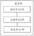
- FIG. 7 is a schematic diagram of the interference measurement device 10 proposed in this application.
- FIG. 8 is a schematic structural diagram of a terminal device 20 applicable to an embodiment of the present application.
- FIG. 9 is a schematic diagram of the interference measurement device 30 proposed in this application.
- FIG. 10 is a schematic structural diagram of a network device 40 suitable for an embodiment of the present application.
- GSM global system for mobile communications
- CDMA code division multiple access
- WCDMA broadband code division multiple access
- GPRS general packet radio service
- LTE long term evolution
- FDD frequency division duplex
- TDD LTE Time division duplex
- UMTS universal mobile telecommunication system
- WiMAX worldwide interoperability for microwave access
- the terminal equipment in the embodiments of this application may refer to user equipment, access terminals, user units, user stations, mobile stations, mobile stations, relay stations, remote stations, remote terminals, mobile equipment, user terminals, terminals, wireless communication equipment, users Agent or user device.
- the terminal device can also be a cellular phone, a cordless phone, a session initiation protocol (SIP) phone, a wireless local loop (WLL) station, a personal digital assistant (PDA), and a wireless communication Functional handheld devices, computing devices, or other processing devices connected to wireless modems, in-vehicle devices, wearable devices, terminal devices in the future 5G network or future evolution of the public land mobile network (PLMN) Terminal equipment, etc., this embodiment of the present application does not limit this.
- SIP session initiation protocol
- WLL wireless local loop
- PDA personal digital assistant
- PLMN public land mobile network
- the network device in the embodiment of the present application may be any device with a wireless transceiving function used to communicate with terminal devices.
- the equipment includes, but is not limited to: evolved Node B (eNB), Radio Network Controller (RNC), Node B (Node B, NB), Base Station Controller (BSC) , Base Transceiver Station (BTS), home base station (for example, Home evolved NodeB, or Home Node B, HNB), baseband unit (BBU), wireless fidelity (Wireless Fidelity, WIFI) system Access point (Access Point, AP), wireless relay node, wireless backhaul node, transmission point (transmission point, TP) or transmission and reception point (transmission and reception point, TRP), etc., can also be 5G, such as NR ,
- the gNB may include a centralized unit (CU) and a DU.
- the gNB may also include an active antenna unit (AAU).
- CU implements part of the functions of gNB
- DU implements part of the functions of gNB.
- the CU is responsible for processing non-real-time protocols and services, and implements radio resource control (radio resource control, RRC), packet data convergence protocol (packet data convergence protocol, PDCP) layer functions.
- RRC radio resource control
- PDCP packet data convergence protocol
- the DU is responsible for processing physical layer protocols and real-time services, and realizes the functions of the radio link control (RLC) layer, media access control (MAC) layer, and physical (PHY) layer.
- RLC radio link control
- MAC media access control
- PHY physical
- the network device may be a device that includes one or more of a CU node, a DU node, and an AAU node.
- the CU can be divided into network equipment in an access network (radio access network, RAN), or the CU can be divided into network equipment in a core network (core network, CN), which is not limited in this application.
- the terminal device or the network device includes a hardware layer, an operating system layer running on the hardware layer, and an application layer running on the operating system layer.
- the hardware layer includes hardware such as a central processing unit (CPU), a memory management unit (MMU), and memory (also referred to as main memory).
- the operating system may be any one or more computer operating systems that implement business processing through processes, for example, Linux operating system, Unix operating system, Android operating system, iOS operating system, or windows operating system.
- the application layer includes applications such as browsers, address books, word processing software, and instant messaging software.
- the embodiments of the application do not specifically limit the specific structure of the execution subject of the methods provided in the embodiments of the application, as long as the program that records the codes of the methods provided in the embodiments of the application can be provided according to the embodiments of the application.
- the execution subject of the method provided in the embodiment of the present application may be a terminal device or a network device, or a functional module in the terminal device or network device that can call and execute the program.
- various aspects or features of the present application can be implemented as methods, devices, or products using standard programming and/or engineering techniques.
- article of manufacture as used in this application encompasses a computer program accessible from any computer-readable device, carrier, or medium.
- computer-readable media may include, but are not limited to: magnetic storage devices (for example, hard disks, floppy disks, or tapes, etc.), optical disks (for example, compact discs (CD), digital versatile discs (DVD)) Etc.), smart cards and flash memory devices (for example, erasable programmable read-only memory (EPROM), cards, sticks or key drives, etc.).
- various storage media described herein may represent one or more devices and/or other machine-readable media for storing information.
- the term "machine-readable storage medium” may include, but is not limited to, wireless channels and various other media capable of storing, containing, and/or carrying instructions and/or data.
- FIG. 1 is a schematic diagram of a system 100 applicable to the interference measurement method according to the embodiment of the present application.
- the system 100 includes a network device 102, and the network device 102 may include one antenna or multiple antennas.
- the network device 102 may additionally include a transmitter chain and a receiver chain.
- both the transmitter chain and the receiver chain may include multiple components related to signal transmission and reception (for example, a processor, modulator, multiplexer, demodulator, demultiplexer, or Antenna, etc.).
- the network device 102 may communicate with terminal devices (for example, the terminal device 116 and the terminal device 122 shown in FIG. 1). However, it is understood that the network device 102 can communicate with any number of terminal devices similar to the terminal device 116 or the terminal device 122.
- the terminal devices 116 and 122 may be various devices that communicate with the network device 102.
- the terminal device 116 may be a cellular phone, a smart phone, a portable computer, a handheld communication device, a handheld computing device, a satellite radio device, a global positioning system, or a PDA. And/or any other suitable device for communicating on the wireless communication system 100.
- the terminal device 116 communicates with antennas 112 and 114.
- the antennas 112 and 114 transmit information to the terminal device 116 through the forward link (also referred to as the downlink) 118, and receive information from the terminal device 116 through the reverse link (also referred to as the uplink) 120.
- the terminal device 122 communicates with the antennas 104 and 106.
- the antennas 104 and 106 send information to the terminal device 122 through the forward link 124, and receive information from the terminal device 122 through the reverse link 126.
- forward link 118 and reverse link 120 may use different frequency bands
- forward link 124 and reverse link 126 may use different frequency bands.
- the forward link 118 and the reverse link 120 can use a common frequency band, and the forward link 124 and the reverse link The link 126 may use a common frequency band.
- Each antenna (or antenna group composed of multiple antennas) and/or area designed for communication is referred to as a sector of the network device 102.
- the antenna group may be designed to communicate with terminal devices in a sector of the area covered by the network device 102.
- the network device can transmit signals to all terminal devices in its corresponding sector through a single antenna or multi-antenna transmit diversity.
- the transmitting antenna of the network device 102 can also use beamforming to improve the signal-to-noise ratio of the forward links 118 and 124.
- the network device 102, the terminal device 116, or the terminal device 122 may be a wireless communication sending device and/or a wireless communication receiving device.
- the wireless communication sending device can encode the data for transmission.
- the wireless communication sending device can acquire (for example, generate, receive from other communication devices, or store in a memory, etc.) a certain number of data bits to be sent to the wireless communication receiving device through a channel.
- Such data bits may be included in a transmission block (or multiple transmission blocks) of data, and the transmission block may be segmented to generate multiple code blocks.
- the communication system 100 may be a PLMN network, a D2D network, an M2M network, an IoT network or other networks.
- FIG. 1 is only a simplified schematic diagram of an example.
- the communication system shown in FIG. 1 may also include other network devices and/or other networks.
- the terminal equipment is not shown in Figure 1 for simplicity.
- the communication system shown in Figure 1 can be a network device communicating with multiple terminal devices, that is, a single network device can transmit data or control signaling to a single or multiple terminal devices; or, the communication system shown in Figure 1 It may be that multiple network devices communicate with one terminal device, that is, multiple network devices can also simultaneously transmit data or control signaling for a single terminal device.
- FIG. 1 is only a simple schematic diagram, which is used to illustrate the applicable scenarios of the interference measurement method provided in the embodiment of the present application, and does not constitute any limitation to the present application.
- High-frequency communication can be used in 5G systems, that is, ultra-high frequency (>6GHz) signals are used to transmit data.
- One of the main problems of high frequency communication is that the signal energy drops sharply with the signal transmission distance, resulting in a short signal transmission distance. Therefore, high-frequency communication adopts analog beam technology and performs weighting processing through a large-scale antenna array to concentrate the signal energy in a small range to form a signal similar to a beam (called an analog beam, or beam for short). Improve the transmission distance.
- the embodiment of the beam in the NR protocol can be a spatial domain filter, or a spatial filter or a spatial parameter.
- the beam used to transmit a signal may be called a transmission beam (Tx beam), and the Tx beam may also be called a spatial domain transmission filter or a spatial transmission parameter (spatial transmission parameter);
- the beam receiving the signal may be referred to as a receiving beam (reception beam, Rx beam), and the Rx beam may also be referred to as a spatial domain receive filter or a spatial receive parameter (spatial RX parameter).
- the transmitting beam may refer to the distribution of signal strength in different directions in space after a signal is transmitted through the antenna
- the receiving beam may refer to the signal strength distribution of the wireless signal received from the antenna in different directions in space.
- beam types include: wide beams, narrow beams or other types of beams.
- Existing communication systems stipulate that beams can be formed by beamforming technology or other technologies.
- the beamforming technology can specifically be digital beamforming technology, analog beamforming technology, or hybrid digital/analog beamforming technology.
- the existing agreement stipulates that there is a one-to-one correspondence between beams and resources.
- the quality of the beam corresponding to a certain resource can be measured by measuring the reference signal transmitted on the resource particle corresponding to a certain resource.
- the network device can configure multiple resources corresponding to the multiple beams to the terminal device, and send reference signals through the resource particles corresponding to the multiple resources, and the terminal device measures the reference Signals and feedback the measured quality of different resources, and the network equipment knows the quality of the beams corresponding to the different resources.
- the beam information can be indicated by the resource corresponding to the beam.
- the network device uses the transmission configuration information (TCI) in the downlink control information (downlink control information, DCI). Field to indicate the information of the physical downlink shared channel (PDSCH) beam of the terminal device.
- TCI transmission configuration information
- DCI downlink control information
- multiple beams having the same or similar communication characteristics may be regarded as one beam.
- One or more antenna ports can be included in a beam for transmitting data channels, control channels, and sounding signals.
- One or more antenna ports forming a beam can also be regarded as an antenna port set.
- the beam refers to the transmission beam of the network device.
- each beam of the network device corresponds to a resource, so the resource index can be used to uniquely identify the beam corresponding to the resource. Since there is a one-to-one correspondence between resources and beams, the following briefly introduces the concept of resources involved in this application.
- the resource index can be used to uniquely identify the beam corresponding to the resource.
- the resource can be an uplink signal resource or a downlink signal resource.
- Uplink signals include but are not limited to: sounding reference signal (SRS) and demodulation reference signal (DMRS); downlink signals include but are not limited to: channel state information reference signal (CSI) -RS), cell specific reference signal (cell specific reference signal, CS-RS), UE specific reference signal (user equipment specific reference signal, US-RS), demodulation reference signal (demodulation reference signal, DMRS), and synchronization signal /Physical broadcast channel block (synchronization system/physical broadcast channel block, SS/PBCH block).
- the SS/PBCH block may be referred to as a synchronization signal block (synchronization signal block, SSB) for short.
- a resource is a data structure, including: related parameters of the uplink/downlink signal corresponding to the resource, such as the type of uplink/downlink signal, the resource element that carries the uplink/downlink signal, and the transmission time of the uplink/downlink signal Sum period, the number of ports used to transmit uplink/downlink signals, etc.
- Each uplink/downlink signal resource has a unique index to identify the uplink/downlink signal resource. It should be understood that the index of the resource may also be referred to as the identifier of the resource, which is not limited in the embodiment of the present application.
- Beam measurement is a measurement process defined in the existing agreement, which mainly includes the following four steps:
- Step 1 The network device sends measurement configuration information to the terminal device.
- the measurement configuration information is sent by the network device to the terminal device through RRC signaling, and mainly includes two parts: resource configuration information and report configuration information.
- Resource configuration information is information related to measurement resources, and is configured in the protocol through a three-level structure (resource Config-resource Set-resource).
- the network device can configure one or more resource configurations for the terminal device (resource Config can also be written as resource Setting), each resource configuration includes one or more resource sets, and each resource set can include one or more resources.
- Each resource configuration, resource set, or resource includes its own index.
- the measurement configuration information also includes some other parameters, such as the period of the resource and the signal type corresponding to the resource.
- Reporting configuration information means that after the terminal device performs a measurement, the measurement result reports related information, which is configured through the report Config in the protocol.
- the network device can configure one or more report Config for the terminal device, and each report Config includes report-related information such as report indicators, report time, report period, and report format.
- the report configuration also includes the resource configuration index, which is used to indicate the result of the report is measured by measuring what resource configuration.
- Step 2 The network device sends a downlink signal on the resource particle corresponding to the resource configured by the resource configuration information, so that the terminal device can determine the quality of each resource (beam) by measuring the downlink signal, which can also be understood as determining the beam corresponding to each resource the quality of.
- Step 3 The terminal device measures the downlink signal according to the measurement configuration information.
- Step 4 The terminal device sends a beam measurement report to the network device.
- the beam measurement report may include the index of one or more resources, the quality of the resources, and so on.
- Table 1 is the report format adopted by the beam measurement in the R15 protocol. Among them, the CRI (CSI-RS Index) field and the SSBRI (SSB Resource Index) field are used to indicate the resource index to be reported. CRI and/or SSBRI can be reported. In Table 1 with Is the length of the CRI field and the SSBRI field. RSRP is the quality of resources.
- RSRP reporting adopts a differential reporting criterion, that is, the best resource RSRP (RSRP field in Table 1) is reported in 7-bit quantization, while other RSRP (differential RSRP in Table 1) fields are reported in 4-bit quantization.
- the above measurement results may be carried in a physical uplink control channel (PUCCH) or a physical uplink shared channel (PUSCH).
- PUCCH physical uplink control channel
- PUSCH physical uplink shared channel
- FIG. 2 is a schematic diagram of a communication system 200 for performing beam measurement. It includes a network device 201, a terminal device 202, multiple transmitting beams, and receiving beams corresponding to the transmitting beams.
- the network device 201 can generate different transmission beams that point to different transmission directions.
- the specific transmission beam used for data transmission is determined by the result of the transmission beam measurement.
- the network device configures multiple measurement resources (resources for short) for the terminal device through measurement configuration information, and each resource corresponds to a transmission beam (that is, the above step 1).
- the network device transmits the measurement signal on the resource particle corresponding to the resource through its corresponding transmit beam (ie, the above step 2), and the terminal device receives the measurement sent on the transmit beam through a receive beam corresponding to the transmit beam
- To determine the quality of the transmission beam (resource) by measuring the measurement signal sent by each transmission beam, such as measuring the Reference Signal Receiving Power (RSRP) of each measurement signal (that is, step 3 above).
- RSRP Reference Signal Receiving Power
- the terminal device selects one or more resources with the largest RSRP, and reports the index of the one or more resources and the corresponding RSRP to the network device (ie, step 4 above). The network device then selects one or more resources (transmit beams) from them for data transmission.
- the terminal device For each transmit beam, the terminal device will also determine an optimal receive beam for receiving the signal on the transmit beam.
- the determination of the receive beam is also determined by the above-mentioned similar beam measurement process. This application does not limit how The determination of the receiving beam may be determined by multiplexing the receiving beam determination scheme in the existing protocol, and the determination of the receiving beam will not be described in detail below.
- the beam measurement process based on the RSRP of the measurement signal shown in FIG. 2 has a problem: the terminal device cannot feed back the interference information between the transmission beams. For example, which transmit beams have strong interference. Furthermore, the network equipment does not know the interference between multiple transmission beams, and when the network equipment transmits data to multiple terminal devices through multiple transmission beams in the same time slot, it is possible to use two transmissions with strong mutual interference. The beam is used for transmission, resulting in data transmission errors, thereby reducing the efficiency of data transmission between network devices and multiple terminal devices.
- 3GPP R16 introduces layer 1-signal to interference plus noise ratio (L1-SINR) measurement in the beam measurement, which is fed back by measuring and reporting L1-SINR Situation of interference between transmit beams.
- the network device configures a channel measurement resource set ⁇ #1, #2, #3, #4 ⁇ and an interference measurement resource set ⁇ #5, #6, #7, #8 ⁇ , and the channel measurement resource set is The measurement signal sent by the transmit beam corresponding to the resource of the, determine the channel measurement resources used for data transmission (such as resources #1 and #2), and then calculate by measuring the measurement signal sent by the transmit beam corresponding to the resource in the interference measurement resource set L1-SINR of channel measurement resources (such as resources #1 and #2).
- L1-SINR layer 1-signal to interference plus noise ratio
- measuring the interference between the beams corresponding to a certain channel measurement resource and a certain interference measurement resource includes: first, the terminal device uses a receiving beam to receive the measurement signal sent by the sending beam corresponding to the channel measurement resource, and calculate The first signal energy of the measurement signal; second, the same number of received reports is used to receive the measurement signal sent by the transmission beam corresponding to the interference measurement resource, and the second signal energy of the measurement signal is calculated; finally, the sum of the first signal energy is calculated
- the ratio of the energy of the second signal is referred to as the interference between the beams corresponding to the channel measurement resource and the interference measurement resource respectively.
- the terminal device After the terminal device performs beam quality measurement and inter-beam interference measurement, it reports the index of the channel measurement resource and the L1-SINR of the channel measurement resource to the network device.
- the calculation of the L1-SINR may use a single interference measurement resource as interference, or all configured interference measurement resources may be used as interference for calculation.
- the L1-SINR of channel measurement resource #1 under the interference of all interference measurement resources can be expressed as (the energy of the measured signal transmitted by the beam corresponding to resource #1 divided by the energy of the measured signal transmitted by the beam corresponding to resource #5-#8 with):
- the receiving beam of the channel measurement resource needs to be used to measure the interference measurement resource, that is, the channel measurement resource and the interference measurement resource need to be measured on the same receiving beam to calculate the channel measurement L1-SINR of the resource. Therefore, when the L1-SINRs of multiple channel measurement resources need to be measured, the receiving beams corresponding to the multiple channel measurement resources need to be used to measure the interference information measurement resources of the multiple channel measurement resources.
- the interference measurement resource is configured only once, the terminal device can only measure the L1-SINR of a single channel measurement resource, and cannot calculate multiple channels. Measure the L1-SINR of the resource.
- L1-SINR used to refer to the signal-to-interference and noise ratio is only an example, and the specific English abbreviation of the signal-to-interference and noise ratio is not limited in this application.
- L1-SINR may also be called SINR, CSI-SINR, SSB-SINR, L1-CSI-SINR or L1-SSB-SINR, etc.
- Figure 3 is a schematic diagram of a method of interference measurement. Including multiple transmitting beams and receiving beams corresponding to the transmitting beams.
- the interference measurement method shown in FIG. 3 implements L1-SINR measurement of multiple channel measurement resources by configuring multiple interference measurement resource sets (the interference measurement resource set may include one or more interference measurement resources).
- the network device configures multiple channel measurement resources and multiple interference measurement resource sets for the terminal device.
- the number of interference measurement resource sets is equal to the number of channel measurement resources in the channel measurement resource set.
- the terminal equipment uses the receiving beams of each channel measurement resource to measure the resources in each interference measurement resource set, and then calculates the L1-SINR of each channel measurement resource.
- the network device using the interference measurement method shown in FIG. 3 needs to configure multiple interference measurement resource sets for the terminal device, and the number of interference measurement resource sets is equal to the number of resources in the channel measurement resource set. For example, if the channel measurement resource set configured by the network device for the terminal device includes 10 resources, it is necessary to configure 10 interference measurement resource sets for the terminal device, and the resource overhead is very large.
- this application proposes an interference measurement method.
- the number of interference measurement resource sets configured for the terminal device through the network device is smaller than the channel configured by the network device for the terminal device. Measure the number of resources to achieve the purpose of saving resource overhead.
- the interference measurement method provided by the embodiment of the present application will be described in detail below in conjunction with FIG. 4 to FIG. 6.
- FIG. 4 is a schematic diagram of an interference measurement method provided by an embodiment of the present application. Including network equipment, terminal equipment and S110-S140.
- the network device sends measurement configuration information to the terminal device.
- the measurement configuration information includes a channel measurement resource set, K interference measurement resource sets, and indication information.
- the indication information is used to instruct the terminal device to report that the number of resources in the channel measurement resource set is K, where K is Positive integer.
- the channel measurement resource set configured by the network device includes M resources, and M is an integer greater than K.
- the M resources may belong to one or more channel measurement resource sets, that is to say, the channel measurement resource set in this application may refer to a channel measurement resource set or a channel measurement composed of multiple channel measurement resource sets Resource collection.
- instruction information can be sent to the terminal device as separate signaling, or carried in the signaling that other network devices need to send to the terminal device. It is not limited to be carried in the above-mentioned measurement configuration information and sent to the terminal. equipment.
- the measurement configuration information may also include reported configuration information, and the reported configuration information is used to configure related information about the measurement result sent by the terminal device to the network device.
- the resources (resources in the channel measurement resource set and resources in the interference measurement resource set) in this application correspond to beams one-to-one, so when the full text involves measurement resources, resource quality, and resource interference information, it can also It is described as measuring the beam corresponding to the resource, the quality of the beam corresponding to the resource, and the interference of the beam corresponding to the resource.
- the “beam” referred to in this application refers to a transmission beam.
- the foregoing channel measurement resource set includes information such as the index, period, and type of each resource in the channel measurement resource set; similarly, the foregoing K interference measurement resource sets include the K interference Information such as the index, period, and type of each resource included in each interference measurement resource set in the measurement resource set.
- the above K can be set to 1, and the network device or protocol can specify that the terminal device only needs to report the index of one resource and the resource and one interference resource set. Interference between resources, which are used to send data.
- Each interference measurement resource set in the above K interference measurement resource sets may include at least one resource, and each resource in the interference measurement resource set corresponds to a transmission beam; similarly, each resource in the channel measurement resource set Corresponds to a transmit beam.
- the quality of the measurement resource involved in this application can be understood as measuring the quality of the beam corresponding to the resource; and the interference information of a certain resource in the measurement channel measurement resource set can be understood as corresponding to the same receiving beam.
- interference measurement resource set #1 includes ⁇ resource #2, resource #3, resource #4, resource #5 ⁇ , that is, the interference of resource #1 can be understood as the transmission beam corresponding to resource #1, which is similar to resource #2, Interference between at least one transmission beam corresponding to at least one of resource #3, resource #4, and resource #5.
- the network device before the network device determines a resource for sending data, the network device usually configures a channel measurement resource set including M resources to the terminal device.
- the terminal device selects the K resources with better quality in the channel measurement resource set to report to the network device, that is, the network device selects K resources with better quality to send data, that is to say, the number of resources used by the network device to send data is usually Will be less than the number of resources included in the channel measurement resource set configured by the network device.
- the number of interference measurement resource sets configured in the embodiment of this application is equal to the number of resources in the channel measurement resource set reported by the terminal device, and the resources in the channel measurement resource set reported by the terminal device The number of is smaller than the total number of resources included in the channel measurement resource set configured by the network device. That is to say, in the embodiment of the present application, the number of interference measurement resource sets configured by the network device is smaller than the number of resources in the channel measurement resource set configured by the network device, so that compared with the interference measurement method shown in FIG. 3, To achieve the purpose of reducing resource overhead, it should be understood that if the interference measurement method shown in FIG. 3 is followed, the network device needs to configure M interference measurement resource sets, and the interference measurement method provided in the embodiment of this application is applied to reduce The overhead of MK interference measurement resource sets is reduced.
- the types of resources included in the channel measurement resource set in this application may be CS-RS resources, US-RS resources, DMRS resources, SSB resources, and channel status information interference measurement (Channel Status Information) introduced in the basic concepts above.
- -Interference Measurement, CSI-IM) resource, zero power channel state information reference signal (ZP CSI-RS) resource or non-zero power channel state information reference signal (none zero power channel state information reference signal) , NZP (CSI-RS) resources, etc. may also be other types of resources, which are not listed here, and can refer to the regulations on the types of resources included in the channel measurement resource set in the existing protocol.
- the resources included in the interference measurement resource set involved in this application mainly refer to NZP CSI-RS resources.
- the interference measurement resource set can be directly
- the resources included in the resource set are understood as NZP CSI-RS resources.
- the role of NZP CSI-RS resources is mainly used to measure channel interference, which means that after the development of communication technology, the resources for measuring channel interference may no longer only include the interference measurement of resource type NZP CSI-RS resources
- the resource set may also include other types of resources that can be used for channel interference measurement.
- This application mainly discusses NZP CSI-RS resources. Other resources that may be used for channel interference measurement are similar to NZP CSI-RS resources. Refer to the NZP CSI-RS resource configuration described in this application, which will not be repeated here.
- the measurement configuration information sent by the network device needs to include the aforementioned channel measurement resource set and K NZP CSI-RS resource sets, and there is no restriction on whether the measurement configuration information includes other resource sets.
- the aforementioned measurement configuration information also includes a CSI-IM resource set, and the resources included in the CSI-IM resource set are used for measuring noise interference, which is different from the aforementioned NZP CSI-RS resource used for measuring channel interference.
- the network device can also configure one or more CSI-IM resource sets for the terminal device to measure noise interference.
- This application mainly considers the measurement of channel interference information, so it mainly involves how to configure the NZP CSI-RS resource set and the number of NZP CSI-RS resource sets. There are no restrictions on the types and number of other resource sets that can be configured. , Do not repeat it.
- NZP CSI-RS resource set there is no restriction on how many NZP CSI-RS resources are included in the NZP CSI-RS resource set in this application, which means that one NZP CSI-RS resource set includes at least one NZP CSI-RS resource. .
- a resource set may refer to a resource set, that is, a network device sends measurement configuration information to a terminal device.
- the measurement configuration information includes a channel measurement resource set and K NZP CSI-RS resource sets, and a number of NZP CSI-RS resource sets. The number is equal to the number of channel measurement resource indexes in one channel measurement resource set to be reported.
- K NZP CSI-RS resource sets can be configured in one resource setting, or K NZP CSI-RS resource sets It can also be configured in multiple resource settings.
- the representation of resource setting in the protocol can also be resource Config, and the representations of resource setting and resource Config in the protocol can be replaced; for example, resource set can refer to resource setting, That is, the network device sends measurement configuration information to the terminal device.
- the measurement configuration information includes a channel measurement resource setting and K NZP CSI-RS resource settings, the number of NZP CSI-RS resource settings and a channel measurement resource setting that needs to be reported The number of channel measurement resource indexes is equal.
- the terminal device first measures the quality of the resources in the channel measurement resource set configured by the network device, and then measures the interference information of the K resources after determining the above K resources according to the measurement results.
- measuring the interference information of the K resources is performed based on one or more resources in a set of interference resources satisfying quasi-co-location of the K resources as interference sources.
- the resources in the above-mentioned channel measurement resource set and the resources in the above-mentioned K interference measurement resource sets need to satisfy a certain first time relationship.
- the first time relationship may be any one of the situations listed below.
- the last time slot in the time slot in which the resource in the channel measurement resource set is located is at least X time slots earlier than the first time slot in the time slot in which the resource in the K interference measurement resource set is located;
- the last symbol in the symbol where the resource in the channel measurement resource set is located is at least X symbols earlier than the first symbol in the symbol where the resource in the K interference measurement resource set is located;
- the time slot set in which the channel measurement resource set is located is at least X time slots earlier than any one of the K time slot sets in which the K interference measurement resource sets are located;
- the symbol set in which the channel measurement resource set is located is at least X symbols earlier than any symbol set in the K symbol sets in which the K interference measurement resource set is located.
- X is a positive integer, and the value of X may be specified by the protocol, or may be reported by the terminal device or determined by other values reported by the terminal device.
- the first time relationship is expressed in the form of a formula, which can be any of the following situations:
- the time slot S CMR where the last resource in time is located in the channel measurement resource set and the time slot S IMR where the earliest one resource in time is located among all the resources included in the K interference measurement resource sets satisfy the following relationship:
- Th slot_1 is the first slot threshold, a positive integer, and the unit is a slot. It means that the time slot in which the resource in the channel measurement resource set is located is at least Th slot_1 time slot apart from the measurement time of all resources included in the K interference measurement resource set.
- Th symbol_1 is the first symbol threshold, which is a positive integer and the unit is a symbol. It means that the time slot in which the resource in the channel measurement resource set is located is at least Th symbol_1 symbols apart from the measurement time of all resources included in the K interference measurement resource set.
- Th slot_1 is the first slot threshold, a positive integer, and the unit is a slot.
- Th symbol_1 is the first symbol threshold, which is a positive integer and the unit is a symbol.
- the K interference resource sets corresponding to the K resources need to meet a certain second time relationship, for example, the second time relationship may be as listed below Any of the situations:
- the last time slot in the time unit where the resource in the previous interference measurement resource set is located in the two arbitrarily adjacent interference measurement resource sets in time of the K interference measurement resource sets is larger than the last time slot in the next interference measurement resource set.
- the first time slot in the time slot where the resource is located is at least Y time slots earlier;
- the last symbol in the symbol where the resource in the previous interference measurement resource set is located in the two adjacent interference measurement resource sets adjacent in time in the K interference measurement resource sets is shorter than the resource in the next interference measurement resource set.
- the first symbol in the symbols is at least Y symbols earlier;
- At least Y time slots are separated between every two time slot sets in the K different time slot sets where the K interference measurement resource sets are located;
- At least Y symbols are spaced between every two symbol sets.
- Y is a positive integer, and the value of Y can be specified by the protocol, or can be reported by the terminal device or determined by other values reported by the terminal device.
- the second time relationship is expressed in the form of a formula, which can be any of the following situations:
- the time slot S IMR_before where the last resource in the time slot S IMR_before of the previous interference measurement resource set in the two interference measurement resource sets adjacent in time is located and the K interference measurement resource sets are in time
- the time slot S IMR_after where the earliest one resource in the next interference measurement resource set in any two adjacent interference measurement resource sets is located satisfies the following relationship:
- Th slot_2 is the second slot threshold, a positive integer, and the unit is a slot.
- K interference measurement resource sets are arbitrarily in time, the symbol F IMR_before of the last interference measurement resource set in the previous interference measurement resource set in time, and the K interference measurement resource sets are arbitrary in time.
- the symbol F IMR_after of the earliest one resource in the next interference measurement resource set in two adjacent interference measurement resource sets satisfies the following relationship:
- Th symbol_2 is the second symbol threshold, which is a positive integer and the unit is a symbol.
- the time slot set S IMR_before_set where the previous interference measurement resource set is located in the two interference measurement resource sets that are arbitrarily adjacent in time and the two interference measurement resource sets that are arbitrarily adjacent in time The time slot set S IMR_after_set in which the next interference measurement resource set in the interference measurement resource set is located satisfies the following relationship:
- Th slot_2 is the second slot threshold, a positive integer, and the unit is a slot.
- the symbol set F IMR_before_set where the previous interference measurement resource set is located in the two interference measurement resource sets that are arbitrarily adjacent in time and the two interference measurement resource sets that are arbitrarily adjacent in time The symbol set F IMR_after_set where the next interference measurement resource set in the measurement resource set is located satisfies the following relationship:
- Th symbol_2 is the second symbol threshold, which is a positive integer and the unit is a symbol.
- the resources included in the channel measurement resource set can be implemented by configuring the value of the parameter periodicityAndOffset Time relationship with the resources included in the interference measurement resource set; for the resources included in the aperiodic channel measurement resource set or the resources included in the interference measurement resource set, the above-mentioned channel measurement can be implemented by configuring the value of the parameter aperiodicTriggeringOffset The time relationship between the resources included in the resource set and the resources included in the interference measurement resource set.
- the parameter periodicityAndOffset or the aperiodicTriggeringOffset of the channel measurement resource set and the interference measurement resource set can be configured to meet the above time relationship.
- the time slot or symbol of the last resource included in the K interference measurement resource sets is Q time slots or symbols earlier than the time slot or symbol of the earliest resource included in the channel measurement resource set.
- Q is a positive integer.
- the network device in order to enable the terminal device to measure the quality of the resources included in the channel measurement resource set, and determine the specific K resources to be reported according to the quality measurement results of the resources in the channel measurement resource set.
- the network device needs to send a first measurement signal to the terminal device according to the configuration of the resources in the channel measurement resource set, and the first measurement signal is used to measure the quality of the resource; further After determining the K resources to be reported, the terminal device also needs to measure the interference information of the K resources. That is to say, the network device needs to send the second measurement signal to the terminal device according to the resource configuration of the K interference measurement resource set , The second measurement signal is used to measure the interference information of the resource. That is to execute S120, the network device sends a measurement signal to the terminal device, and the measurement signal includes the first measurement signal and the second measurement signal described above.
- the network device sends M first measurement signals to the terminal device according to the configuration of each resource in the channel measurement resource set.
- the first measurement signal is used to measure the quality of the resource for sending the first measurement signal; the network device sends the first measurement signal according to the K
- the configuration of the resources in each interference measurement resource set in the interference measurement resource set sends K second measurement signal sets to the terminal device.
- the first measurement signal and the second measurement signal set are used to measure the transmission of the second measurement signal set.
- the terminal device needs to receive and measure the above-mentioned first measurement signal and the second measurement signal, that is, perform S130, and the terminal device measures the quality of the resource and the interference information of the resource.
- the main process that the terminal device can measure the quality of the resource and the interference information of the resource includes the following steps:
- Step 1 The network device respectively sends M first measurement signals to the terminal device according to the resource configuration of the M resources in the channel measurement resource set.
- Step 2 After receiving the M first measurement signals according to the receiving beams corresponding to the M resources, the terminal device measures the M first measurement signals respectively. For example, the RSRP of the M first measurement signals are respectively measured, and the quality of the M resources for respectively sending the M first measurement signals is judged based on the RSRP of the M first measurement signals.
- Step 3 The terminal device selects the K resource related information that needs to be reported to the network device in the channel measurement resource set according to the measurement results of the M first measurement signals, for example, determines that the quality of the M first measurement signals is better.
- the related information of the K resources corresponding to the K first measurement signals of needs to be reported.
- the related information of the K resources includes the index of each of the K resources, the RSRP of the K first measurement signals corresponding to the K resources, and other related information.
- the resource index may be CRI or SSBRI, it should be understood that the resource index in this application can also be referred to as resource identifier and other names.
- the existing protocol stipulates how the terminal device determines the quality of the resource according to the first measurement signal sent on each resource in the measurement channel measurement resource set. This is not repeated in this application, and the existing protocol can be reused Perform the measurement in the prescribed method.
- the terminal device may be any of the following possibilities for the terminal device to determine which of the M resources included in the channel measurement resource set to report related information of which K resources:
- the terminal device determines the quality of each of the M resources according to the result of measuring the first measurement signal, and ranks the quality of each resource from good to bad (there is no resource with the same quality), and then ranks in the top K Of resources are identified as K resources to be reported.
- the terminal device measures the first measurement signal received on the 10 resources, and learns that the RSRP of the first measurement signal received on the 10 resources is 10, 9, and respectively. 8, 7, 6, 5, 4, 3, 2, 1.
- the RSRP of the first measurement signal reported by the terminal device is the index of the first 5 resources of 10, 9, 8, 7, and 6, respectively.
- the terminal device determines the quality of each of the M resources according to the result of measuring the first measurement signal, and sorts the quality of each resource from good to bad.
- the quality of multiple resources is the same, the multiple resources The resources in are in adjacent positions in the sequence after sorting, and the top K resources are identified as K resources to be reported.
- the terminal device measures the first measurement signal received on the 10 resources, and learns that the RSRP of the first measurement signal received on the 10 resources is 10, 10, and 10, respectively. 10, 8, 8, 5, 4, 3, 2, 1.
- the RSRP of the first measurement signal reported by the terminal device is the index of the first 5 resources of 10, 10, 10, 8, and 8, respectively.
- Step 4 After the terminal device determines the K resources to be reported, it measures the K L1-SINRs corresponding to the K resources.
- the L1-SINR of the resource may also be referred to as the SINR or CQI or RSRQ of the resource.
- the network device sends K second measurement signal sets to the terminal device according to the configuration of the resources in the K interference measurement resource sets.
- K resources are the same as the receiving beams corresponding to the K interference measurement resource sets; or the K resources and the K interference measurement resource sets have the same TCI state; or the K resources and the K interference measurement resource sets have the same TCI state Have the same QCL assumptions.
- the QCL type can be Type D or Type A.
- the K resources are in one-to-one correspondence with the K interference measurement resource sets, and the terminal device uses the receiving beam for receiving the first measurement signal to receive the second measurement signal set sent by the interference measurement resource set corresponding to the resource.
- the terminal device can calculate the quality of the K resources, and calculate the interference between the K resources and at least one resource in the K interference measurement resource sets. That is, the terminal device assumes that the resources in the K interference measurement resource sets are quasi-colocated (QCLed) respectively with the K resources to be reported.
- QLed quasi-colocated
- the following L1-SINR calculation method can be used to calculate the L1-SINR of resource #1:
- P 1 is the energy of the first measurement signal of resource #1
- P interf is the signal energy of the second measurement signal set received by the receiving beam corresponding to resource #1, or the energy of the second measurement signal set that has the same TCI state as resource #1
- the signal energy of the second measurement signal set may be the signal energy of a second measurement signal in the second measurement signal set, or the signal energy of the second measurement signal set may be all the first measurement signals included in the second measurement signal set. 2. The sum or linear average of the signal energy of the measurement signal.
- P other is other interference energy
- P other is the CSI-IM resource set configured by the network device, and the signal energy of the third measurement signal set sent to the terminal device according to the resource configuration in the CSI-IM resource set, or NZP Energy other than the signal energy of the first measurement signal corresponding to the CSI-RS resource set, or energy other than the signal energy of the second measurement signal corresponding to the NZP CSI-RS interference measurement resource set.
- NZP Energy other than the signal energy of the first measurement signal corresponding to the CSI-RS resource set, or energy other than the signal energy of the second measurement signal corresponding to the NZP CSI-RS interference measurement resource set.
- the above QCL assumption may refer to the index of the resource included in the QCL-info of type D included in the TCI state of the resource in the channel measurement resource set, indicating that the resource and the resource index indication included in the QCL-info The resources correspond to the same receiving beam.
- the K resources mentioned above correspond to the K interference measurement resource sets in a one-to-one correspondence, and any one of the following corresponding methods may be adopted:
- the K interference measurement resource sets are sorted according to the time sequence of being measured in the time domain, they correspond to the K resources according to the index from small to large or from large to small;
- the sequence of the resource sets corresponding to the terminal equipment measuring 5 interference measurement resource sets is interference measurement resource set #1, interference measurement resource set #3, interference measurement Resource set #5, interference measurement resource set #2, interference measurement resource set #4; 5 resources (resource #1 ⁇ resource #5) are sorted as resource #1 ⁇ resource #5 according to the index from small to large, so there are K
- the one-to-one correspondence between resources and K interference measurement resource sets is:
- Interference measurement resource set #1 corresponds to resource #1
- interference measurement resource set #3 corresponds to resource #2
- interference measurement resource set #5 corresponds to resource #3
- interference measurement resource set #2 corresponds to resource #4
- interference measurement resource set #4 Corresponding to resource #5.
- the K interference measurement resource sets are sorted according to the time sequence of being measured in the time domain, they are in a one-to-one correspondence with the K resources in the order of network device configuration (that is, the order in which each resource is configured in the resource set);
- the sequence of the resource sets corresponding to the terminal equipment measuring 5 interference measurement resource sets is interference measurement resource set #1, interference measurement resource set #3, interference measurement Resource set #5, interference measurement resource set #2, interference measurement resource set #4; 5 resources (resource #1 to resource #5) are arranged in the order of resource #1, resource #3, resource #5, resource #2 Resource #4, the one-to-one correspondence between K resources and K interference measurement resource sets is:
- Interference measurement resource set #1 corresponds to resource #1
- interference measurement resource set #3 corresponds to resource #3
- interference measurement resource set #5 corresponds to resource #5
- interference measurement resource set #2 corresponds to resource #2
- interference measurement resource set #4 Corresponds to resource #4.
- the K interference measurement resource sets are sorted according to the time sequence of being measured in the time domain, they correspond to the K resources according to the measured resource (beam) quality (such as RSRP) from small to large or from large to small. ;
- the sequence of the resource sets corresponding to the terminal equipment measuring 5 interference measurement resource sets is interference measurement resource set #1, interference measurement resource set #3, interference measurement Resource set #5, interference measurement resource set #2, interference measurement resource set #4; 5 resources (resource #1 ⁇ resource #5) corresponding to the resource quality (RSRP size) are 5, 2, 4, 1, 3, respectively ,
- the resource #1-resource#3-resource#5-resource#2-resource#4 is obtained in order from largest to smallest, and the one-to-one correspondence between K resources and K interference measurement resource sets is:
- Interference measurement resource set #1 corresponds to resource #1
- interference measurement resource set #3 corresponds to resource #3
- interference measurement resource set #5 corresponds to resource #5
- interference measurement resource set #2 corresponds to resource #2
- interference measurement resource set #4 Corresponds to resource #4.
- the K interference measurement resource sets are sorted according to the time sequence of being measured in the time domain, they correspond to the K resources according to the order in which the resources are reported (sorted);
- the sequence of the resource sets corresponding to the terminal equipment measuring 5 interference measurement resource sets is interference measurement resource set #1, interference measurement resource set #3, interference measurement Resource set #5, interference measurement resource set #2, interference measurement resource set #4;
- the terminal device reports 5 resources (resource #1 ⁇ resource #5), and the reporting sequence is resource #1-resource#3-resource#5-resource #2- ⁇ #4, the one-to-one correspondence between K resources and K interference measurement resource sets is:
- Interference measurement resource set #1 corresponds to resource #1
- interference measurement resource set #3 corresponds to resource #3
- interference measurement resource set #5 corresponds to resource #5
- interference measurement resource set #2 corresponds to resource #2
- interference measurement resource set #4 Corresponds to resource #4.
- the set of K interference measurement resources corresponds to the K resources in the order of increasing index or the order of decreasing index according to the order of increasing or decreasing index;
- interference measurement resource set #1 ⁇ interference measurement resource set #5 For example, 5 interference measurement resource sets (interference measurement resource set #1 ⁇ interference measurement resource set #5); 5 resources (resource #1 ⁇ resource #5) are sorted as resource #1 ⁇ resource# in ascending order of index. 5.
- the one-to-one correspondence between K resources and K interference measurement resource sets is:
- Interference measurement resource set #1 corresponds to resource #1
- interference measurement resource set #2 corresponds to resource #2
- interference measurement resource set #3 corresponds to resource #3
- interference measurement resource set #4 corresponds to resource #4
- interference measurement resource set #5 Corresponding to resource #5.
- the K interference measurement resource sets are in a one-to-one correspondence with the K resources in the order of network device configuration (that is, the order in which each resource is configured in the resource set) according to the index from large to small or from small to large;
- interference measurement resource set #1 to interference measurement resource set #5 For example, 5 interference measurement resource sets (interference measurement resource set #1 to interference measurement resource set #5); the configuration order of 5 resources (resource #1 to resource #5) is resource #1, resource #3, resource #5 , Resource #2, resource #4, the one-to-one correspondence between K resources and K interference measurement resource sets is:
- Interference measurement resource set #1 corresponds to resource #1
- interference measurement resource set #2 corresponds to resource #3
- interference measurement resource set #3 corresponds to resource #5
- interference measurement resource set #4 corresponds to resource #2
- interference measurement resource set #5 Corresponds to resource #4.
- the K interference measurement resource sets correspond to the K resources according to the measured resource (beam) quality (such as RSRP) from small to large or from large to small according to the order of the index from large to small or from small to large;
- the measured resource (beam) quality such as RSRP
- interference measurement resource set #1 to interference measurement resource set #5 For example, five interference measurement resource sets (interference measurement resource set #1 to interference measurement resource set #5); the resource quality (RSRP size) corresponding to 5 resources (resource #1 to resource #5) is 5, 2, 4. 1, 3, from the largest to the smallest to get the resource #1-resource#3-resource#5-resource#2-resource#4, then the one-to-one correspondence between K resources and K interference measurement resource sets is:
- Interference measurement resource set #1 corresponds to resource #1
- interference measurement resource set #2 corresponds to resource #3
- interference measurement resource set #3 corresponds to resource #5
- interference measurement resource set #4 corresponds to resource #2
- interference measurement resource set #5 Corresponds to resource #4.
- the K interference measurement resource sets correspond to the K resources according to the order in which the resources are reported (sorted) according to the order of the index from large to small or from small to large;
- interference measurement resource set #1 For example, 5 interference measurement resource sets (interference measurement resource set #1 ⁇ interference measurement resource set #5); the terminal device reports 5 resources (resource #1 ⁇ resource #5), and the reporting sequence is resource #1-resource#3- Resource#5-Resource#2-Resource#4, the one-to-one correspondence between K resources and K interference measurement resource sets is:
- Interference measurement resource set #1 corresponds to resource #1
- interference measurement resource set #2 corresponds to resource #3
- interference measurement resource set #3 corresponds to resource #5
- interference measurement resource set #4 corresponds to resource #2
- interference measurement resource set #5 Corresponds to resource #4.
- the K interference measurement resource sets are sorted according to the order of network equipment configuration (such as the sequence in the interference measurement resource set list), and the K resources are sorted in the order of the index from small to large or from large to small One-to-one correspondence
- the configuration sequence of 5 interference measurement resource sets is interference measurement resource set #1, interference measurement resource set #3, interference measurement resource set #5, interference Measurement resource set #2, interference measurement resource set #4; 5 resources (resource #1 ⁇ resource #5) are sorted as resource #1 ⁇ resource #5 according to the index from small to large, then K resources and K interference measurements
- the resource collection corresponds to:
- Interference measurement resource set #1 corresponds to resource #1
- interference measurement resource set #3 corresponds to resource #2
- interference measurement resource set #5 corresponds to resource #3
- interference measurement resource set #2 corresponds to resource #4
- interference measurement resource set #4 Corresponding to resource #5.
- the K interference measurement resource sets are sorted according to the order of network device configuration (such as the sequence in the interference measurement resource set list), and the K resources are sorted in the order of network device configuration (that is, each resource is configured in the resource set Order) one-to-one correspondence;
- the configuration sequence of 5 interference measurement resource sets is interference measurement resource set #1, interference measurement resource set #3, interference measurement resource set #5, interference Measurement resource set #2, interference measurement resource set #4; 5 resources (resource #1 ⁇ resource #5) are configured in order of resource #1, resource #3, resource #5, resource #2, resource #4, then K
- the one-to-one correspondence between two resources and K interference measurement resource sets is:
- Interference measurement resource set #1 corresponds to resource #1
- interference measurement resource set #3 corresponds to resource #3
- interference measurement resource set #5 corresponds to resource #5
- interference measurement resource set #2 corresponds to resource #2
- interference measurement resource set #4 Corresponds to resource #4.
- the K interference measurement resource sets are sorted according to the order of the network device configuration (such as the sequence in the interference measurement resource set list), and the K resources are sorted according to the measured resource (beam) quality (such as RSRP) from small to large Or one-to-one correspondence from big to small;
- the measured resource (beam) quality such as RSRP
- the configuration sequence of 5 interference measurement resource sets is interference measurement resource set #1, interference measurement resource set #3, interference measurement resource set #5, interference Measurement resource set #2, interference measurement resource set #4; 5 resources (resource #1 ⁇ resource #5) corresponding to the resource quality (RSRP size) are 5, 2, 4, 1, 3, in descending order Obtain resource#1-resource#3-resource#5-resource#2-resource#4, the one-to-one correspondence between K resources and K interference measurement resource sets is:
- Interference measurement resource set #1 corresponds to resource #1
- interference measurement resource set #3 corresponds to resource #3
- interference measurement resource set #5 corresponds to resource #5
- interference measurement resource set #2 corresponds to resource #2
- interference measurement resource set #4 Corresponds to resource #4.
- the K interference measurement resource sets are sorted according to the sequence of network device configuration (such as the sequence in the interference measurement resource set list), which corresponds to the K resources according to the order of the resource report (sorting required);
- the configuration sequence of 5 interference measurement resource sets (interference measurement resource set #1 to interference measurement resource set #5) is interference measurement resource set #1, interference measurement resource set #3, interference measurement resource set #5, interference Measurement resource set #2, interference measurement resource set #4; the terminal device reports 5 resources (resource #1 ⁇ resource #5), and the reporting sequence is resource #1-resource#3-resource#5-resource#2-resource#4 , Then the one-to-one correspondence between K resources and K interference measurement resource sets is:
- Interference measurement resource set #1 corresponds to resource #1
- interference measurement resource set #3 corresponds to resource #3
- interference measurement resource set #5 corresponds to resource #5
- interference measurement resource set #2 corresponds to resource #2
- interference measurement resource set #4 Corresponds to resource #4.
- the measurement result is the quality information and interference information of the K resources in the above-mentioned channel measurement resource set, and the interference information of the K resources may be the signal to interference plus noise ratio of the K resources. , SINR), or channel quality information (channel quantity information, CQI) of K resources, or reference signal received quality (RSRQ) of K resources, or L1-SINR of K resources.
- SINR SINR
- channel quality information channel quantity information, CQI
- RSRQ reference signal received quality
- the measurement result includes: the index of the K resources in the channel measurement resource set and at least one of the signal-to-noise-to-interference ratio SINR of the K resources, the channel quality information CQI, and the reference signal reception quality RSRQ. Further, the measurement result also includes information such as RSRP of K resources and an index of resources in the interference measurement resource set corresponding to the K resources.
- the above-mentioned measurement configuration information further includes report configuration information.
- the report configuration information is used to indicate how the terminal device performs measurement and what needs to be reported by the terminal device.
- Reporting configuration information in existing protocols can be called report Config.
- a network device can configure one or more report Configs for a terminal device.
- Each report Config includes reporting indicators, reporting time, reporting period, and Reporting format and other information related to reporting, where the reporting index refers to the index that needs to be reported by the terminal device, such as RSRP and/or CRI.
- the reported configuration also includes an index of resource configuration (resource setting or resource Config), which is used to indicate which resource configuration the terminal device measures.
- the reported configuration in this application includes the resource configuration of the K interference measurement resource sets mentioned above. And the index of the resource configuration to which the channel measurement resource set composed of M channel measurement resources belongs; or, if the K interference measurement resource set and the channel measurement resource set belong to one resource configuration, the report configuration includes the resource configuration index.
- this application mainly involves the improvement of the report Quantity included in the reported configuration information in the existing protocol, and there is no restriction on other parameters that need to be included in the reported configuration information specified in the existing protocol, and will not be repeated .
- the report Quantity in the embodiment of the present application may be configured to at least one of the following possibilities:
- the report Quantity may include signal to interference plus noise ratio (SINR) and resource index (cri or ssb index) but not RSRP.
- SINR signal to interference plus noise ratio
- the report Quantity is configured as ssb-Index-SINR or cri-SINR or ssb-Index-L1-SINR or cri-L1-SINR.
- the report Quantity may include SINR and RSRP, but not the channel measurement resource index (cri or ssb index).
- the report Quantity is configured as RSRP-SINR or SINR-RSRP.
- the measurement result sent by the terminal device to the network device in S140 is that the terminal device only reports the L1-RSRP corresponding to each resource and the L1-SINR corresponding to each resource.
- the reported L1-RSRP and L1-SINR can be measured based on the same resource or based on different resources.
- the report Quantity may include SINR but not RSRP and resource index (cri or ssb index).
- the report Quantity is configured as SINR or L1-SINR.
- the report Quantity may include SINR, RSRP and channel measurement resource index (cri or ssb index).
- the report Quantity is configured as ssb-Index-RSRP-SINR or cri-RSRP-SINR or ssb-Index-SINR-RSRP or cri-SINR-RSRP.
- one implementation manner of the measurement result sent by the terminal device to the network device in S140 is that the terminal device reports the resource index and the RSRP corresponding to each resource and the L1-SINR corresponding to each resource.
- Report Quantity can include SINR and interference measurement resource index (cri or ssb index) (index cri-SINR can be reported), for example, configured as ssb-Index-SINR-interference measurement resource index or cri-SINR-interference measurement resource index or SINR-Interference measurement resource index.
- SINR interference measurement resource index
- cri-SINR index cri-SINR can be reported
- the measurement result sent by the terminal device to the network device in S140 is that the terminal device reports the resource index and the L-SINR corresponding to each resource and the interference measurement resource index (for example, used for L1-SINR calculation) The index of the resource in the interference measurement resource set).
- the terminal device reports the L-SINR corresponding to each resource and the interference measurement resource index (for example, the index of the resource in the interference measurement resource set used for L1-SINR calculation), instead of reporting the channel measurement resource index of.
- the interference measurement resource index for example, the index of the resource in the interference measurement resource set used for L1-SINR calculation
- Report Quantity can include one of SINR and interference measurement resource index (cri or ssb index).
- report Quantity is configured as ssb-Index-SINR, cri-SINR, ssb-Index-interference measurement resource index, cri-interference Measurement resource index, ssb-Index-RSRP-SINR, cri-RSRP-SINR, ssb-Index-RSRP-interference measurement resource index or cri-RSRP-interference measurement resource index.
- one implementation of the measurement result sent by the terminal device to the network device in S140 is that the terminal device reports the resource index and the L-SINR corresponding to each resource and the interference measurement resource index (for example, used for L1-SINR calculation) The index of the resource in the interference measurement resource set); another implementation is that the terminal device reports the L-SINR corresponding to each resource and the interference measurement resource index (for example, the resource in the interference measurement resource set used for L1-SINR calculation) Index) instead of reporting the resource index.
- the network device configures the channel measurement resource set and the K interference measurement resource sets to the terminal device through measurement configuration information, the channel measurement resource set includes M resources, and the network device instructs The information indicates that the terminal device reports K resources in the channel measurement resource set. That is, in the method flow shown in FIG. 4, the number of resources in the channel measurement resource set reported by the terminal device is equal to the number of interference measurement resource sets configured by the network device. Therefore, compared with the method shown in FIG. 3 according to the process, the purpose of saving resources and expenses is achieved. Further, in order to further save resource overhead, the network device may also configure L interference measurement resource sets, and L is a positive integer less than K. The following describes in detail in conjunction with FIG. 5, how the network device configures the channel measurement resource set and L interference measurement resource sets for the terminal device.
- Fig. 5 is a schematic diagram of another interference measurement method provided by an embodiment of the present application. Including network equipment, terminal equipment and S210-S240.
- S210 The network device sends first measurement configuration information to the terminal device.
- the first measurement configuration information includes a channel measurement resource set, L interference measurement resource sets, and indication information.
- the indication information is used to instruct the terminal device to report that the number of resources in the channel measurement resource set is K, where: K is an integer greater than 1, and L is a positive integer less than K.
- the channel measurement resource set configured by the network device includes M resources, and M is an integer greater than K.
- the M resources may belong to one or more channel measurement resource sets, that is to say, the channel measurement resource set in this application may refer to a channel measurement resource set or a channel measurement composed of multiple channel measurement resource sets Resource collection.
- the foregoing indication information may be sent to the terminal device as a separate signaling, or carried in the signaling that other network devices need to send to the terminal device, and is not limited to be carried in the foregoing first measurement configuration information.
- this application only limits the first measurement configuration information to include a channel measurement resource set, L interference measurement resource sets and indication information, but it does not limit the first measurement configuration information to only include the above-mentioned information.
- It includes reported configuration information, which is used to configure related information about the measurement results sent by the terminal device to the network device.
- the foregoing channel measurement resource set includes information such as the index, period, and type of each resource in the channel measurement resource set; similarly, the foregoing L interference measurement resource sets include the L interferences. Information such as the index, period, and type of each resource included in each interference measurement resource set in the measurement resource set.
- Each interference measurement resource set in the foregoing L interference measurement resource sets may include at least one resource, and each resource in the interference measurement resource set corresponds to a transmission beam; similarly, each resource in the channel measurement resource set Corresponds to a transmit beam.
- the quality of the measurement resource involved in this application can be understood as measuring the quality of the beam corresponding to the resource; and the interference information of a certain resource in the measurement channel measurement resource set can be understood as corresponding to the same receiving beam
- the network device before the network device determines the resource for sending data, the network device usually configures a channel measurement resource set including M resources to the terminal device.
- M may be greater than or equal to K. Integer.
- the terminal device selects K resources with better quality in the channel measurement resource set and reports to the network device, that is, the network device selects K resources with better quality to send data, that is to say, the number of resources used by the network device to send data will usually be It is less than the number of resources included in the channel measurement resource set configured by the network device.
- the number of interference measurement resource sets configured in the embodiment of this application is less than the number of resources in the channel measurement resource set reported by the terminal device, and the resources in the channel measurement resource set reported by the terminal device The number of is smaller than the total number of resources included in the channel measurement resource set configured by the network device. That is to say, in the embodiment of the present application, the number of interference measurement resource sets configured by the network device is smaller than the number of resources in the channel measurement resource set configured by the network device, so that compared with the interference measurement method shown in FIG. 3, To achieve the purpose of reducing resource overhead, it should be understood that if the interference measurement method shown in FIG. 3 is followed, the network device needs to configure M interference measurement resource sets, and the interference measurement method provided in the embodiment of this application is applied to reduce The overhead of ML interference measurement resource sets is reduced.
- the types of resources included in the channel measurement resource set and the types of resources included in the interference measurement resource set in this application are similar to those described in FIG. 4, and will not be repeated here.
- the first measurement configuration information sent by the network device needs to include the aforementioned channel measurement resource set and L NZP CSI-RS resource sets, and it does not matter whether the first measurement configuration information includes other resource sets. limit.
- the first measurement configuration information shown in FIG. 5 may also include a CSI-IM resource set.
- the CSI-IM resource set refer to the description of the CSI-IM resource set in FIG. 4, which will not be repeated here.
- the terminal device first measures the quality of the resources in the channel measurement resource set configured by the network device, and then determines the above K resources according to the measurement results, then measures at least L of the K resources Interference information.
- measuring the interference information of at least L of the K resources is performed based on one or more resources in the set of interference resources whose at least L resources satisfy quasi-colocation as interference sources.
- the resources in the foregoing channel measurement resource set and the resources in the foregoing L interference measurement resource sets need to satisfy a certain third time relationship.
- the third time relationship may be any one of the situations listed below.
- the last time slot in the time slot in which the resource in the channel measurement resource set is located is at least X time slots earlier than the first time slot in the time slot in which the resource in the L interference measurement resource set is located;
- the last symbol in the symbol where the resource in the channel measurement resource set is located is at least X symbols earlier than the first symbol in the symbol where the resource in the L interference measurement resource set is located;
- the time slot set in which the channel measurement resource set is located is at least X time slots earlier than any one of the L time slot sets in which the L interference measurement resource sets are located;
- the symbol set in which the channel measurement resource set is located is at least X symbols earlier than any symbol set in the L symbol sets in which the L interference measurement resource sets are located.
- X is a positive integer, and the value of X may be specified by the protocol, or may be reported by the terminal device or determined by other values reported by the terminal device.
- the third time relationship is expressed in the form of a formula, which can be any of the following situations:
- the time slot S CMR where the last resource in time is located in the channel measurement resource set and the time slot S IMR where the earliest resource in time is located among all the resources included in the L interference measurement resource sets satisfy the following relationship:
- Th slot_3 is the third slot threshold, a positive integer, and the unit is a slot.
- Th symbol_3 is the third symbol threshold, which is a positive integer and the unit is a symbol.
- Th slot_3 is the third slot threshold, a positive integer, and the unit is a slot.
- Th symbol_3 is the third symbol threshold, which is a positive integer and the unit is a symbol.
- the fourth time relationship may be the following cases Any of:
- the last time slot in the time unit where the resource in the previous interference measurement resource set is located in the two arbitrarily adjacent interference measurement resource sets in time for the L interference measurement resource sets is larger than the last time slot in the next interference measurement resource set.
- the first time slot in the time slot where the resource is located is at least Y time slots earlier;
- the last symbol in the symbol where the resource in the previous interference measurement resource set is located in the two arbitrarily adjacent interference measurement resource sets in time of the L interference measurement resource sets is shorter than the resource in the next interference measurement resource set.
- the first symbol in the symbols is at least Y symbols earlier;
- At least Y time slots are separated between every two time slot sets in the L different time slot sets where the L interference measurement resource sets are located;
- At least Y symbols are spaced between every two symbol sets.
- Y is a positive integer, and the value of Y can be specified by the protocol, or can be reported by the terminal device or determined by other values reported by the terminal device.
- the fourth time relationship is expressed in the form of a formula, which can be any of the following situations:
- the L interference measurement resource sets are arbitrarily adjacent in time in the previous interference measurement resource set in the previous interference measurement resource set, the time slot S IMR_before where the last resource in time is located and the L interference measurement resource sets are in time
- the time slot S IMR_after where the earliest one resource in the next interference measurement resource set in any two adjacent interference measurement resource sets is located satisfies the following relationship:
- Th slot_4 is the fourth slot threshold, a positive integer, and the unit is a slot.
- L interference measurement resource sets are arbitrarily adjacent in time in the previous interference measurement resource set in the previous interference measurement resource set, the symbol F IMR_before where the last resource in time is located and the L interference measurement resource sets are arbitrary in time
- the symbol F IMR_after of the earliest one resource in the next interference measurement resource set in two adjacent interference measurement resource sets satisfies the following relationship:
- Th symbol_4 is the fourth symbol threshold, which is a positive integer and the unit is a symbol.
- the time slot set S IMR_before_set where the previous interference measurement resource set is located in the two interference measurement resource sets that are arbitrarily adjacent in time and the two interference measurement resource sets that are arbitrarily adjacent in time The time slot set S IMR_after_set in which the next interference measurement resource set in the interference measurement resource set is located satisfies the following relationship:
- Th slot_4 is the fourth slot threshold, a positive integer, and the unit is a slot.
- the symbol set F IMR_before_set where the previous interference measurement resource set is located in the two interference measurement resource sets that are arbitrarily adjacent in time and the two interference measurement resource sets that are arbitrarily adjacent in time The symbol set F IMR_after_set where the next interference measurement resource set in the measurement resource set is located satisfies the following relationship:
- Th symbol_4 is the fourth symbol threshold, which is a positive integer and the unit is a symbol.
- the channel measurement resource set can be included in the channel measurement resource set by configuring the value of the parameter periodicity and offset.
- the network device configures the channel measurement resource set and L
- the time relationship needs to be satisfied, but if the network device configures the channel measurement resource set and the interference measurement resource set for other purposes, the time relationship between the channel measurement resource set and the interference measurement resource set can still be Yes, the time unit of the resource included in the interference measurement resource set is earlier than the time of the resource included in the channel measurement resource set in the time domain.
- the time slot or symbol of the last resource of the resources included in the L interference measurement resource sets is y time slots or symbols earlier than the time slot or symbol of the earliest resource included in the channel measurement resource set. y is a positive integer.
- the network device in order to enable the terminal device to measure the quality of the resources included in the above-mentioned channel measurement resource set, and determine the specific K resources that need to be reported according to the quality measurement results of the resources in the channel measurement resource set.
- the network device needs to send a first measurement signal to the terminal device according to the configuration of the resources in the channel measurement resource set, and the first measurement signal is used to measure the quality of the resource; further After determining the K resources that need to be reported, the terminal device also needs to measure the interference information of at least L of the K resources. That is to say, the network device needs to report to the terminal device according to the resource configuration of the L interference measurement resource set.
- Send a second measurement signal where the second measurement signal is used to measure the interference information of the resource. That is to execute S220, the network device sends a measurement signal to the terminal device, and the measurement signal includes the first measurement signal and the second measurement signal described above.
- the network device sends M first measurement signals to the terminal device according to the configuration of each resource in the channel measurement resource set.
- the first measurement signal is used to measure the quality of the resource for sending the first measurement signal; the network device sends the first measurement signal according to the K
- the configuration of the resources in each interference measurement resource set in the interference measurement resource set sends K second measurement signal sets to the terminal device.
- the first measurement signal and the second measurement signal set are used to measure the transmission of the second measurement signal set.
- the terminal device needs to receive and measure the above-mentioned first measurement signal and the second measurement signal, that is, perform S230, and the terminal device measures the quality of the resource and the interference information of the resource.
- the main process that the terminal device can measure the quality of the resource and the interference information of the resource includes the following steps:
- Step 1 The network device respectively sends M first measurement signals to the terminal device according to the resource configuration of the M resources in the channel measurement resource set.
- Step 2 After the terminal device measures the M first measurement signals according to the M first measurement signals corresponding to the M resources, respectively. For example, the RSRP of the M first measurement signals are respectively measured, and the quality of the M resources for respectively sending the M first measurement signals is judged based on the RSRP of the M first measurement signals.
- Step 3 The terminal device selects the K resource related information that needs to be reported to the network device in the channel measurement resource set according to the measurement results of the M first measurement signals, for example, determines that the quality of the M first measurement signals is better.
- the related information of the K resources corresponding to the K first measurement signals of needs to be reported.
- the related information of the K resources includes the index of each of the K resources, the RSRP of the K first measurement signals corresponding to the K resources, and other related information.
- the resource index may be CRI or SSBRI, it should be understood that the resource index in this application can also be referred to as resource identifier and other names.
- the existing protocol stipulates how the terminal device determines the quality of the resource according to the first measurement signal sent on each resource in the measurement channel measurement resource set. This is not repeated in this application, and the existing protocol can be reused Perform the measurement in the prescribed method.
- Step 4 After the terminal device determines the K resources to be reported, the K L1-SINRs corresponding to at least L of the K resources are measured.
- the L1-SINR of the resource may also be referred to as the SINR or CQI or RSRQ of the resource.
- the network device sends L second measurement signal sets to the terminal device according to the configuration of the resources in the L interference measurement resource sets.
- the terminal device can calculate that L of the K resources are different from the set of L interference measurement resources. Interference between at least one resource.
- the L resources in the K resources are respectively the same as the receiving beams corresponding to the L interference measurement resource sets; in other words, the L resources in the K resources have the same TCI state as the L interference measurement resource sets; or The L resources among the K resources respectively have the same QCL hypothesis as the L interference measurement resource set sets.
- the QCL type can be Type D or Type A.
- the L resources are in one-to-one correspondence with the L interference resource sets, and the terminal device uses a receiving beam corresponding to a certain resource among the L resources to receive the L second measurement signal sets corresponding to the interference measurement resource set corresponding to the resource. Therefore, the terminal device can calculate the quality of the K resources, and calculate the interference between the L resources in the K resources and at least one resource in the set of L interference measurement resources. That is, the terminal device assumes that the resources in the L interference measurement resource sets and the L resources in the K resources to be reported are QCLed.
- the above K is equal to 3 (the 3 resources are resource #1 to resource #3), and L is equal to 2 (the 2 interference measurement resource sets are interference measurement resource set #1 and interference measurement resource set #2), and the terminal equipment
- interference measurement resource set #1 is quasi-co-located with resource #1, that is, the SINR or CQI or RSRQ of resource #1 is determined based on one or more resources in interference measurement resource set #1 as interference sources;
- interference measurement resource set #2 is quasi-co-located with resource #2, that is, the SINR or CQI or RSRQ of resource #2 is determined based on one or more resources in interference measurement resource set #2 as interference sources.
- the terminal device can calculate that more than L resources (P resources) among the K resources and L interference measurement For interference between at least one resource in the resource set, P is an integer greater than L and less than K.
- P resources in K resources are the same as the receiving beams corresponding to L interference measurement resource sets; or P resources in K resources and L interference measurement resource sets have the same TCI state; or K
- the P resources in the resources and the L interference measurement resource sets have the same QCL hypothesis.
- the QCL type can be Type D or Type A.
- the P resources correspond to the L interference measurement resource sets, at least one interference measurement resource set in the L interference measurement resource sets corresponds to multiple resources, and the terminal device receives the receiving beams corresponding to the multiple resources to receive the multiple resources
- the second measurement signal set corresponding to the corresponding interference measurement resource set Therefore, the terminal device can calculate the quality of the K resources, and calculate the interference between the P resources in the K resources and at least one resource in the set of L interference measurement resources. That is, the terminal device assumes that the resources in the L interference measurement resource sets and the P resources among the K resources to be reported are QCLed.
- the foregoing terminal device determining the L resources from the K resources may be selecting the L resources with the largest resource quality (for example, the RSRP of the first measurement signal) among the K resources.
- the three determined resources are resource #1, resource #2, and resource #3.
- the terminal device uses receiving beam #1, receiving beam #2, and receiving beam #2 to receive the three resources respectively.
- Three sets of second measurement signals corresponding to two sets of interference resources.
- the foregoing terminal device determining the L resources from the K resources may be selected to receive the largest resources of the L RSRPs with different beams among the K resources.
- the three determined resources are resource #1, resource #2, and resource #4 (receive beams of resource #2 and resource #3 are the same and the resource quality ratio of resource #2 The quality of resource #3 is good, so resource #3 is skipped), and the terminal equipment uses receiving beam #1, receiving beam #2, and receiving beam #3 to respectively receive the three second measurement signal sets corresponding to the three interference resource sets .
- L resources correspond to L interference measurement resource sets one-to-one, which is similar to the one-to-one correspondence between K resources and K interference measurement resource sets shown in FIG. 4, and will not be repeated here;
- the foregoing P resources correspond to L interference measurement resource sets.
- At least one interference measurement resource set in the L interference measurement resource sets may correspond to multiple resources.
- the above-mentioned one-to-one correspondence is changed to one-to-many. , Which is similar to the one-to-one correspondence between K resources and K interference measurement resource sets shown in FIG. 4, and will not be repeated here.
- the L1-SINR of L resources can be calculated, or when L receive beams correspond to P resources, P can be calculated. L1-SINR of each channel measurement resource.
- the receiving beams corresponding to resource #2 and resource #3 are the same (receiving beam #2), so when receiving beam #2 is used to receive the second measurement signal set corresponding to an interference measurement resource set, you can Calculate the L1-SINR of resource #2 and resource #3.
- the measurement result is the quality information and interference information of the K resources in the above-mentioned channel measurement resource set.
- the interference information of the K resources may be the SINR of the K resources, or the CQI of the K resources, or the RSRQ of the K resources , Or L1-SINR of K resources.
- the measurement result includes: the index of the K resources in the channel measurement resource set and the signal-to-noise-to-interference ratio SINR of the L resources in the K resources, the channel quality information CQI, and the reference signal reception quality RSRQ At least one of them. Further, the measurement result also includes information such as RSRP of K resources, and an interference measurement resource set corresponding to L of the K resources.
- the measurement result includes: the index of the K resources in the channel measurement resource set and the signal-to-noise-to-interference ratio SINR of the P resources among the K resources, the channel quality information CQI, and the reference signal reception quality RSRQ At least one of them. Further, the measurement result also includes information such as RSRP of K resources, and interference measurement resource sets corresponding to P resources among the K resources.
- the number of L1-SINR measured is less than K, it means that some resources have no L1-SINR measurement result.
- one implementation is to report only the index of the resource with the L1-SINR measurement result and the corresponding L1-SINR. That is, the indexes of at least L resources among the K resources and the corresponding L1-SINR are reported.
- Another implementation is to report the measured L1-SINR (that is, report the index of the resource regardless of whether there is a corresponding L1-SINR). It is possible to report only the L1-SINR of at least L of the K resources.
- L1-SINR measured, that is, when multiple resources correspond to the same receiving beam, or the multiple resources have the same TCI state, or the multiple resources have the same QCL hypothesis
- the receiving For beam measurement an interference measurement resource set, or an interference measurement resource set with the same TCI state, or an interference measurement resource set with the same QCL assumption is determined to determine an interference measurement resource set, and L1-SINRs of multiple resources can be calculated.
- the number of L1-SINR measured is greater than L, and all L1-SINRs are reported.
- the reporting format of the resource index and L1-SINR can adopt the arrangement shown in Table 3, that is, each resource is adjacent to its L1-SINR.
- the corresponding L1-SINR position behind the channel measurement resource (such as resource #3) without the L1-SINR measurement result is left blank.
- the index resource index may also be arranged adjacently, and all L1-SINRs may be arranged adjacently for reporting.
- the L1-SINR field corresponding to the channel measurement resource without the L1-SINR measurement result can be filled with a special value, such as 0.
- the above-mentioned first measurement configuration information further includes report configuration information.
- the report configuration information is used to indicate how the terminal device performs measurement and what needs to be reported by the terminal device.
- the configuration information reported in the existing protocol can be called report Config.
- the network device can configure one or more report Config for the terminal device.
- Each report Config includes the report index, report time, report period and report format.
- Report related information where the reported index refers to the index that needs to be reported by the terminal device, such as RSRP and/or CRI.
- the reported configuration also includes an index of resource configuration (resource setting or resource Config), which is used to indicate which resource configuration the terminal device measures.
- the reported configuration in this application includes the resource configuration to which the aforementioned L interference measurement resource sets belong And the index of the resource configuration to which the channel measurement resource set composed of M channel measurement resources belongs; or, if the above-mentioned L interference measurement resource sets and channel measurement resource sets belong to one resource configuration, the reported configuration includes the resource configuration index.
- this application mainly involves the improvement of the report Quantity included in the reported configuration information in the existing protocol, and there is no restriction on other parameters that need to be included in the reported configuration information specified in the existing protocol, and will not be repeated .
- the report Quantity in this embodiment can be configured into any form of report Quantity shown in FIG. 4, which is not repeated here.
- the network device configures a channel measurement resource set to the terminal device through the measurement configuration information and the first measurement configuration information respectively.
- the channel measurement resource set includes M resources, and the network device passes The indication information instructs the terminal device to report K resources in the channel measurement resource set. That is, in the method procedures shown in FIG. 4 and FIG. 5, the terminal device needs to determine the number of resources in the reported channel measurement resource set through the instruction of the network device. Further, considering that the network device may have determined which K resources in a channel measurement resource set are used for sending data through other means, but cannot determine the interference between the K resources and other resources, the network device can directly Configure the K resources and K interference measurement resource sets to determine the interference information of the K resources. The following describes in detail with reference to FIG. 6 how the network device configures K resources and L interference measurement resource sets for the terminal device.
- FIG. 6 is a schematic diagram of another interference measurement method provided by an embodiment of the present application. Including network equipment, terminal equipment and S310-S340.
- S310 The network device sends second measurement configuration information to the terminal device.
- the second measurement configuration information includes K resources and K interference measurement resource sets, where K is a positive integer.
- the network device knows which K resources are used to send data. Specifically, the network device may be determined according to the measurement result of the historical terminal device.
- the network device determines that the resources used to send data are the above-mentioned K resources through the historical measurement results, that is to say, when the channel measurement resource set is currently configured, the network device has learned that it is used to send data
- the network device can directly form a channel measurement resource set and configure the K interference measurement resource sets mentioned above to the terminal device when configuring the channel measurement resource set.
- the network device knows the resources used for data transmission in advance, so the network device does not need to configure M resources when configuring the channel measurement resource set for the terminal device, which further reduces the resource overhead. For example, the network device allocates 10 resources to the terminal device, the terminal device measures and reports 2 resource indexes, the network device knows that the 2 resources are used for data transmission, and based on the historical measurement result, the network device determines 2 resources for data transmission Under the premise of resources, only the two resources and two interference measurement resource sets need to be configured, thereby reducing the overhead of interference measurement resources.
- this application only limits the second measurement configuration information to include K resources and K interference measurement resource sets, but it does not limit the second measurement configuration information to only include the above information.
- it may also include report configuration information.
- the reported configuration information is used to configure the related information of the measurement result sent by the terminal device to the network device.
- the foregoing channel measurement resource set includes information such as the index, period, and type of each resource in the channel measurement resource set; similarly, the foregoing K interference measurement resource sets include the K interference Information such as the index, period, and type of each resource included in each interference measurement resource set in the measurement resource set.
- Each interference measurement resource set in the above K interference measurement resource sets may include at least one resource, and each resource in the interference measurement resource set corresponds to a transmission beam; similarly, each resource in the channel measurement resource set Corresponds to a transmit beam.
- the quality of the measurement resource involved in this application can be understood as measuring the quality of the beam corresponding to the resource; and the interference information of a certain resource in the measurement channel measurement resource set can be understood as corresponding to the same receiving beam.
- the types of resources included in the channel measurement resource set and the types of resources included in the interference measurement resource set in this application are similar to those described in FIG. 4, and will not be repeated here.
- the second measurement configuration information sent by the network device needs to include the above K resources and K NZP CSI-RS resource sets, and there is no restriction on whether the second measurement configuration information includes other resource sets.
- the second measurement configuration information shown in FIG. 6 may also include a CSI-IM resource set.
- the CSI-IM resource set refer to the description of the CSI-IM resource set in FIG. 4, which will not be repeated here.
- the K interference resource sets need to satisfy a certain fifth time relationship.
- the fifth time relationship may be any of the following cases :
- the last time slot in the time unit where the resource in the previous interference measurement resource set is located in the two arbitrarily adjacent interference measurement resource sets in time of the K interference measurement resource sets is larger than the last time slot in the next interference measurement resource set.
- the first time slot in the time slot where the resource is located is at least X time slots earlier;
- the last symbol in the symbol where the resource in the previous interference measurement resource set is located in the two adjacent interference measurement resource sets adjacent in time in the K interference measurement resource sets is shorter than the resource in the next interference measurement resource set.
- the first symbol in the symbols is at least X symbols earlier;
- At least X symbols are spaced between every two symbol sets.
- X is a positive integer, and the value of X may be specified by the protocol, or may be reported by the terminal device or determined by other values reported by the terminal device.
- the fifth time relationship is expressed in the form of a formula, which can be any of the following situations:
- the time slot S IMR_before where the last resource in the time slot S IMR_before of the previous interference measurement resource set in the two interference measurement resource sets adjacent in time is located and the K interference measurement resource sets are in time
- the time slot S IMR_after where the earliest one resource in the next interference measurement resource set in any two adjacent interference measurement resource sets is located satisfies the following relationship:
- Th slot_5 is the fifth slot threshold, a positive integer, and the unit is a slot.
- K interference measurement resource sets are arbitrarily in time, the symbol F IMR_before of the last interference measurement resource set in the previous interference measurement resource set in time, and the K interference measurement resource sets are arbitrary in time.
- the symbol F IMR_after of the earliest one resource in the next interference measurement resource set in two adjacent interference measurement resource sets satisfies the following relationship:
- Th symbol_5 is the fifth symbol threshold, which is a positive integer and the unit is a symbol.
- the time slot set S IMR_before_set where the previous interference measurement resource set is located in the two interference measurement resource sets that are arbitrarily adjacent in time and the two interference measurement resource sets that are arbitrarily adjacent in time The time slot set S IMR_after_set in which the next interference measurement resource set in the interference measurement resource set is located satisfies the following relationship:
- Th slot_5 is the fifth slot threshold, a positive integer, and the unit is a slot.
- the symbol set F IMR_before_set where the previous interference measurement resource set is located in the two interference measurement resource sets that are arbitrarily adjacent in time and the two interference measurement resource sets that are arbitrarily adjacent in time The symbol set F IMR_after_set where the next interference measurement resource set in the measurement resource set is located satisfies the following relationship:
- Th symbol_5 is the fifth symbol threshold, which is a positive integer and the unit is a symbol.
- the network device in the embodiment shown in FIG. 6 has known K resources for sending data, so there is no need to limit the time relationship between the K resources and the aforementioned K interference resource sets, because the K resources The resource must be earlier in time than the above K interference resource sets.
- the network device needs to send a measurement signal to the terminal device according to the configuration of the K resources and the resources in the K interference measurement resource set, namely In step S320, the network device sends a measurement signal to the terminal device, where the measurement signal includes the first measurement signal and the second measurement signal described above.
- the network device sends K first measurement signals to the terminal device according to the configuration of the above K resources; the network device sends to the terminal device respectively according to the configuration of the resources in each interference measurement resource set in the K interference measurement resource sets K second measurement signal sets, where the first measurement signal and the second measurement signal set are used to measure at least one resource in the interference measurement resource set that sends the second measurement signal set, and the information received by the receiving beam receiving the second measurement signal set Interference between resources corresponding to the first measurement signal.
- the terminal device needs to receive and measure the above-mentioned first measurement signal and the second measurement signal, that is, perform S330, and the terminal device measures the interference information of the resource.
- what the terminal device can measure the interference information of the resource may be that after the terminal device determines the K resources that need to be reported, it measures the K L1-SINRs corresponding to the K resources.
- the L1-SINR of the resource may also be referred to as the SINR or CQI or RSRQ of the resource.
- the network device sends K second measurement signal sets to the terminal device according to the configuration of the resources in the K interference measurement resource sets.
- K resources are the same as the receiving beams corresponding to the K interference measurement resource sets; or the K resources and the K interference measurement resource sets have the same TCI state; or the K resources and the K interference measurement resource sets have the same TCI state Have the same QCL assumptions.
- the QCL type can be Type D or Type A.
- the K resources are in one-to-one correspondence with the K interference measurement resource sets, and the terminal device uses the receiving beam for receiving the first measurement signal to receive the second measurement signal set sent by the interference measurement resource set corresponding to the resource.
- the terminal device can calculate the quality of the K resources, and calculate the interference between the K resources and at least one resource in the K interference measurement resource set. That is, the terminal device assumes that the resources in the K interference measurement resource sets are quasi-coordinated QCLed with the K resources to be reported.
- the K resources mentioned above correspond to the K interference measurement resource sets in a one-to-one relationship, which are similar to those shown in FIG. 4 and will not be described here.
- the measurement result is the interference information of the K resources in the above-mentioned channel measurement resource set.
- the interference information of the K resources may be the SINR of K resources, or the CQI of K resources, or the RSRQ of K resources, or K L1-SINR for each resource.
- the L1-SINR of at least K resources reported by the terminal device may be arranged and reported in the report format according to any one of the following methods:
- the terminal device reports the L1-SINR corresponding to the K resources according to the K resource indexes from small to large or from large to small;
- the terminal device reports the L1-SINR corresponding to the K resources according to the configuration order of the K resources;
- the multiple L1-SINRs are arranged in ascending order or descending order.
- the terminal device may also report the index of the resource in the interference measurement resource set used for L1-SINR measurement.
- the network device may configure L interference measurement resource sets, and specifically, measure at least L of the K resources based on the L interference measurement resource sets.
- the interference information of is similar to the interference information of at least L of the K resources measured on the basis of the L interference measurement resource sets in FIG. 5, which will not be illustrated here.
- the size of the sequence numbers of the foregoing processes does not mean the order of execution, and the execution order of the processes should be determined by their functions and internal logic, and should not correspond to the implementation process of the embodiments of this application. Constitute any limitation.
- the interference measurement method provided by the embodiment of the present application is described in detail above with reference to FIGS. 4-6, and the interference measurement apparatus provided by the embodiment of the present application is described in detail below with reference to FIGS. 7-10.
- the device 10 includes a receiving unit 110, a sending unit 130, and a processing unit 120.
- the receiving unit 110 is configured to receive measurement configuration information sent by a network device, where the measurement configuration information includes a channel measurement resource set, K interference measurement resource sets, and indication information, and the indication information is used to instruct the terminal device to report the
- the number of resources in the channel measurement resource set is K, where K is a positive integer;
- the processing unit 120 is configured to determine the SINR or CQI of the first resource by using one or more resources in the set of interference measurement resources that are quasi-coordinated with the first resource in the K interference measurement resource sets as interference sources Or RSRQ, wherein the first resource is any one of the K resources in the channel measurement resource set;
- the sending unit 130 is configured to send the measurement result to the network device.
- the last time unit in the time unit where the resource in the channel measurement resource set is located is at least one earlier than the first time unit in the time unit where the resource in the K interference measurement resource set is located Time unit.
- the last time unit in the time unit where the resource in the previous interference measurement resource set in the two adjacent interference measurement resource sets is arbitrarily adjacent in time is greater than the last time unit
- the first time unit in the time unit where the resource in the interference measurement resource set is located is at least one time unit earlier.
- the measurement report result includes: the index of the K resources in the channel measurement resource set, and the signal-to-noise-to-interference ratio SINR of the K resources, the channel quality information CQI, and the reference signal reception quality RSRQ at least one.
- the apparatus 10 completely corresponds to the terminal equipment in the method embodiment, and the apparatus 10 may be the terminal equipment in the method embodiment, or a chip or functional module inside the terminal equipment in the method embodiment.
- the corresponding units of the apparatus 10 are used to execute the corresponding steps executed by the terminal device in the method embodiments shown in FIGS. 4-6.
- the receiving unit 110 in the apparatus 10 executes the steps of the terminal device receiving in the method embodiment. For example, perform step 110 of receiving network device sending measurement configuration information in FIG. 4, perform step 120 of receiving network device sending measurement signal in FIG. 4, perform step 210 of receiving network device sending first measurement configuration information in FIG. 5, and execute diagram Step 220 of receiving the measurement signal sent by the network device in 5, step 310 of receiving the second measurement configuration information sent by the network device in FIG. 6 and step 320 of receiving the measurement signal sent by the network device in FIG. 6 are executed.
- the processing unit 120 executes the steps implemented or processed inside the terminal device in the method embodiment. For example, step 130 of calculating resource quality and resource interference information in FIG. 4, step 230 of calculating resource quality and resource interference information in FIG.
- step 330 of calculating resource interference information in FIG. 6 are performed.
- the sending unit 130 executes the steps sent by the terminal device in the method embodiment. For example, step 140 of sending the measurement result to the network device in FIG. 4, step 240 of sending the measurement result to the network device in FIG. 5, and step 340 of sending the measurement result to the network device in FIG. 6 are performed.
- the receiving unit 110 and the sending unit 130 may constitute a transceiver unit, and have both receiving and sending functions.
- the processing unit 120 may be a processor.
- the sending unit 130 may be a receiver.
- the receiving unit 110 may be a transmitter. The receiver and transmitter can be integrated to form a transceiver.
- FIG. 8 is a schematic structural diagram of a terminal device 20 applicable to an embodiment of the present application.
- the terminal device 20 can be applied to the system shown in FIG. 1.
- FIG. 8 only shows the main components of the terminal device.
- the terminal device 20 includes a processor, a memory, a control circuit, an antenna, and an input and output device.
- the processor is used to control the antenna and the input/output device to send and receive signals
- the memory is used to store a computer program
- the processor is used to call and run the computer program from the memory to execute the corresponding process executed by the terminal device in the interference measurement method proposed in this application And/or operation. I won't repeat them here.
- FIG. 8 only shows a memory and a processor. In actual terminal devices, there may be multiple processors and memories.
- the memory may also be referred to as a storage medium or a storage device, etc., which is not limited in the embodiment of the present application.
- FIG. 9 is a schematic diagram of the interference measurement device 30 proposed in the present application.
- the device 30 includes a sending unit 310 and a receiving unit 320.
- the sending unit 310 is configured to send measurement configuration information to a terminal device, where the measurement configuration information includes a channel measurement resource set, K interference measurement resource sets, and indication information, and the indication information is used to instruct the terminal device to report the channel
- the number of resources in the measurement resource set is K, where K is a positive integer;
- the sending unit 310 is further configured to send a measurement signal to the terminal device according to the channel measurement resource set and the configuration of the resources in the K interference measurement resource sets
- the receiving unit 320 is configured to receive the measurement result sent by the terminal device.
- the last time unit in the time unit where the resource in the channel measurement resource set is located is at least one earlier than the first time unit in the time unit where the resource in the K interference measurement resource set is located Time unit
- the last time unit in the time unit where the resource in the previous interference measurement resource set in the two adjacent interference measurement resource sets is arbitrarily adjacent in time is greater than the last time unit
- the first time unit in the time unit where the resource in the interference measurement resource set is located is at least one time unit earlier;
- the measurement result includes: indexes of K resources in the channel measurement resource set, and at least one of the signal-to-noise-to-interference ratio SINR, channel quality information CQI, and reference signal reception quality RSRQ of the K resources One.
- SINR signal-to-noise-to-interference ratio
- CQI channel quality information
- RSRQ reference signal reception quality
- the resources in the K interference measurement resource sets are respectively quasi-coordinated with the K resources in the channel measurement resource set.
- the SINR or CQI or RSRQ of the first resource among the K resources in the channel measurement resource set is based on interference measurement that satisfies quasi-co-location with the first resource in the K interference measurement resource set
- One or more resources in the resource set are determined as interference sources, and the first resource is any one of the K resources.
- the apparatus 30 completely corresponds to the network equipment in the method embodiment, and the apparatus 30 may be the network equipment in the method embodiment, or a chip or functional module inside the network equipment in the method embodiment.
- the corresponding units of the device 30 are used to execute the corresponding steps executed by the network device in the method embodiments shown in FIGS. 4-6.
- the sending unit 310 in the apparatus 30 executes the steps of the network device sending in the method embodiment. For example, perform step 110 of sending measurement configuration information to a terminal device in Figure 4, perform step 120 of sending a measurement signal to a terminal device in Figure 4, perform step 210 of sending first measurement configuration information to a terminal device in Figure 5, and perform Step 220 of sending a measurement signal to the terminal device in FIG. 5, step 310 of sending the second measurement configuration information to the terminal device in FIG. 6 and step 320 of sending a measurement signal to the terminal device in FIG. 6 are performed.
- the receiving unit 320 executes the steps of the network device receiving in the method embodiment. For example, step 140 of the receiving terminal device in FIG. 4 sending the measurement result, step 240 of the receiving terminal device in FIG. 5 sending the measurement result, and step 340 of the receiving terminal device in FIG. 6 sending the measurement result are executed.
- the apparatus 30 may further include a processing unit, which is configured to execute the steps implemented or processed inside the network device in the method embodiment.
- the receiving unit 320 and the sending unit 310 may constitute a transceiving unit and have the functions of receiving and sending at the same time.
- the processing unit may be a processor.
- the transmitting unit 310 may be a receiver.
- the receiving unit 320 may be a transmitter. The receiver and transmitter can be integrated to form a transceiver.
- FIG. 10 is a schematic structural diagram of a network device 40 applicable to an embodiment of the present application, which can be used to implement the function of the network device in the foregoing interference measurement method.
- a network device 40 can be a schematic structural diagram of a base station.
- the network device can be applied to the system shown in Figure 1.
- the network device 40 may include one or more radio frequency units, such as a remote radio unit (RRU) 401 and one or more base band units (BBU).
- the baseband unit may also be referred to as a digital unit (DU) 402.
- the RRU 401 may be called a transceiver unit, and corresponds to the sending unit 310 in FIG. 9.
- the transceiver unit 401 may also be called a transceiver, a transceiver circuit, or a transceiver, etc., and it may include at least one antenna 4011 and a radio frequency unit 4012.
- the transceiving unit 401 may include a receiving unit and a transmitting unit, the receiving unit may correspond to a receiver (or receiver, receiving circuit), and the transmitting unit may correspond to a transmitter (or transmitter, transmitting circuit).
- the RRU 401 part is mainly used for receiving and sending of radio frequency signals and conversion of radio frequency signals and baseband signals, for example, for sending the control information described in the foregoing embodiments to the terminal device.
- the part 402 of the BBU is mainly used for baseband processing and control of the base station.
- the RRU 401 and the BBU 402 may be physically set together, or may be physically separated, that is, a distributed base station.
- the BBU 402 is the control center of the network device, and may also be called a processing unit, which may correspond to the processing unit 330, and is mainly used to complete baseband processing functions, such as channel coding, multiplexing, modulation, and spreading.
- the BBU (processing unit) 402 can be used to control the network device 40 to execute the operation procedure of the network device in the foregoing method embodiment, for example, to determine the length of the symbol carrying the control information of the terminal device.
- the BBU 402 may be composed of one or more single boards, and multiple single boards may jointly support a radio access network of a single access standard (for example, an LTE system, or a 5G system), or may separately support Wireless access networks of different access standards.
- the BBU 402 also includes a memory 4021 and a processor 4022.
- the memory 4021 is used to store necessary instructions and data.
- the memory 4021 stores the codebook in the above-mentioned embodiment and the like.
- the processor 4022 is used to control the base station to perform necessary actions, for example, to control the base station to execute the operation procedure of the network device in the foregoing method embodiment.
- the memory 4021 and the processor 4022 may serve one or more single boards. In other words, the memory and the processor can be set separately on each board. It can also be that multiple boards share the same memory and processor. In addition, necessary circuits can be provided on each board.
- the above-mentioned BBU 402 can be used to perform the actions described in the previous method embodiments implemented by the network device, and the RRU 401 can be used to perform the actions described in the previous method embodiments that the network device sends to or receives from the terminal device.
- the RRU 401 can be used to perform the actions described in the previous method embodiments that the network device sends to or receives from the terminal device.
- the network equipment is not limited to the form shown in FIG. 10, and may also be in other forms: for example, including BBU and adaptive radio unit (ARU), or including BBU and active antenna unit (AAU). ); It can also be customer premises equipment (CPE), or other forms, which are not limited in this application.
- BBU and adaptive radio unit ARU
- BBU and active antenna unit AAU
- CPE customer premises equipment
- the network device 40 shown in FIG. 10 can implement the network device functions involved in the method embodiments of FIGS. 4-6.
- the operations and/or functions of each unit in the network device 40 are respectively for implementing the corresponding process executed by the network device in the method embodiment of the present application. To avoid repetition, detailed description is omitted here.
- the structure of the network device illustrated in FIG. 10 is only a possible form, and should not constitute any limitation in the embodiment of the present application. This application does not exclude the possibility of other network device structures that may appear in the future.
- the network equipment in the above device embodiments corresponds to the network equipment or terminal equipment in the terminal equipment and method embodiments, and the corresponding modules or units execute the corresponding steps.
- the communication unit transmits the receiving or sending in the method embodiments.
- other steps can be executed by the processing unit (processor).
- the processing unit processor
- An embodiment of the present application also provides a communication system, which includes the aforementioned network device and one or more terminal devices.
- the present application also provides a computer-readable storage medium that stores instructions in the computer-readable storage medium.
- the computer executes the network device in the method shown in FIGS. 4-6. The various steps performed.
- the present application also provides a computer-readable storage medium that stores instructions in the computer-readable storage medium.
- the computer executes the above-mentioned method shown in FIG. 4 to FIG. 6. The various steps performed.
- This application also provides a computer program product containing instructions.
- the computer program product runs on a computer, the computer executes the steps performed by the network device in the method shown in FIGS. 4-6.
- This application also provides a computer program product containing instructions.
- the computer program product runs on a computer, the computer executes the steps performed by the terminal device in the method shown in FIGS. 4-6.
- This application also provides a chip including a processor.
- the processor is used to read and run a computer program stored in the memory to execute the corresponding operation and/or process performed by the terminal device in the interference measurement method provided in this application.
- the chip further includes a memory, the memory and the processor are connected to the memory through a circuit or a wire, and the processor is used to read and execute the computer program in the memory.
- the chip further includes a communication interface, and the processor is connected to the communication interface.
- the communication interface is used to receive data and/or information that needs to be processed, and the processor obtains the data and/or information from the communication interface, and processes the data and/or information.
- the communication interface can be an input and output interface.
- This application also provides a chip including a processor.
- the processor is used to call and run a computer program stored in the memory to execute the corresponding operation and/or process performed by the network device in the interference measurement method provided in this application.
- the chip further includes a memory, the memory and the processor are connected to the memory through a circuit or a wire, and the processor is used to read and execute the computer program in the memory.
- the chip further includes a communication interface, and the processor is connected to the communication interface.
- the communication interface is used to receive data and/or information that needs to be processed, and the processor obtains the data and/or information from the communication interface, and processes the data and/or information.
- the communication interface can be an input and output interface.
- the disclosed system, device, and method may be implemented in other ways.
- the device embodiments described above are only illustrative.
- the division of the units is only a logical function division, and there may be other divisions in actual implementation, for example, multiple units or components can be combined or It can be integrated into another system, or some features can be ignored or not implemented.
- the displayed or discussed mutual coupling or direct coupling or communication connection may be indirect coupling or communication connection through some interfaces, devices or units, and may be in electrical, mechanical or other forms.
- the units described as separate components may or may not be physically separated, and the components displayed as units may or may not be physical units, that is, they may be located in one place, or they may be distributed on multiple network units. Some or all of the units may be selected according to actual needs to achieve the objectives of the solutions of the embodiments.
- each unit in each embodiment of the present application may be integrated into one processing unit, or each unit may exist alone physically, or two or more units may be integrated into one unit.
- the function is implemented in the form of a software functional unit and sold or used as an independent product, it can be stored in a computer readable storage medium.
- the technical solution of this application essentially or the part that contributes to the existing technology or the part of the technical solution can be embodied in the form of a software product, and the computer software product is stored in a storage medium, including Several instructions are used to make a computer device (which may be a personal computer, a server, or a network device, etc.) execute all or part of the steps of the method described in each embodiment of the present application.
- the aforementioned storage media include: U disk, mobile hard disk, read-only memory (Read-Only Memory, ROM), random access memory (Random Access Memory, RAM), magnetic disk or optical disk and other media that can store program code .
Landscapes
- Engineering & Computer Science (AREA)
- Signal Processing (AREA)
- Computer Networks & Wireless Communication (AREA)
- Mobile Radio Communication Systems (AREA)
Abstract
La présente invention concerne un procédé et un appareil de mesure d'interférence. Le procédé comprend les étapes suivantes : un dispositif de réseau envoie tout d'abord à un dispositif terminal des informations de configuration de mesure comprenant un ensemble de ressources de mesure de canal, K ensembles de ressources de mesure d'interférence et des informations d'indication, les informations d'indication étant utilisées pour ordonner au dispositif de terminal de reporter K ressources dans l'ensemble de ressources de mesure de canal et K étant un nombre entier positif ; le dispositif de réseau envoie ensuite un signal de mesure au dispositif de terminal en fonction de la configuration de ressources dans l'ensemble de ressources de mesure de canal et des K ensembles de ressources de mesure d'interférence ; et le dispositif de réseau reçoit finalement un résultat de mesure envoyé par le dispositif de terminal. Le procédé de mesure d'interférence de la présente invention permet de réduire le surdébit de ressources en rendant le nombre d'ensembles de ressources de mesure d'interférence configurés par le dispositif de réseau pour mesurer une interférence inter-ressources égal au nombre de ressources rapportées par le dispositif de terminal dans l'ensemble de ressources de mesure de canal configuré par le dispositif de réseau pour mesurer une qualité de ressource.
Applications Claiming Priority (2)
| Application Number | Priority Date | Filing Date | Title |
|---|---|---|---|
| CN201910285888.0A CN111818546B (zh) | 2019-04-10 | 2019-04-10 | 干扰测量的方法和装置 |
| CN201910285888.0 | 2019-04-10 |
Publications (1)
| Publication Number | Publication Date |
|---|---|
| WO2020207269A1 true WO2020207269A1 (fr) | 2020-10-15 |
Family
ID=72750881
Family Applications (1)
| Application Number | Title | Priority Date | Filing Date |
|---|---|---|---|
| PCT/CN2020/081665 Ceased WO2020207269A1 (fr) | 2019-04-10 | 2020-03-27 | Procédé et appareil de mesure d'interférence |
Country Status (2)
| Country | Link |
|---|---|
| CN (1) | CN111818546B (fr) |
| WO (1) | WO2020207269A1 (fr) |
Cited By (6)
| Publication number | Priority date | Publication date | Assignee | Title |
|---|---|---|---|---|
| US20210320702A1 (en) * | 2020-04-10 | 2021-10-14 | Qualcomm Incorporated | Techniques for reported resource indicator and maximum resource number for signal-to-interference-and-noise ratio (sinr) in a wireless communication system |
| US20210377766A1 (en) * | 2020-05-29 | 2021-12-02 | Qualcomm Incorporated | Signaling for group-based signal to interference plus noise ratio (sinr) beam report |
| CN114390554A (zh) * | 2020-10-20 | 2022-04-22 | 维沃移动通信有限公司 | 信道状态信息确定方法、上报设置确定方法、装置及相关设备 |
| US20230345518A1 (en) * | 2022-04-21 | 2023-10-26 | Qualcomm Incorporated | Options for indicating reception quasi co-location (qcl) information |
| WO2024077504A1 (fr) * | 2022-10-12 | 2024-04-18 | Qualcomm Incorporated | Réalisation de mesures associées à des ressources de mesure de canal à l'aide de sous-ensembles de faisceaux de réception restreints |
| WO2025260246A1 (fr) * | 2024-06-18 | 2025-12-26 | Oppo广东移动通信有限公司 | Procédé et appareil de configuration de ressources, équipement terminal et dispositif réseau |
Families Citing this family (5)
| Publication number | Priority date | Publication date | Assignee | Title |
|---|---|---|---|---|
| CN114554520B (zh) * | 2020-11-26 | 2024-10-25 | 维沃移动通信有限公司 | 干扰测量方法、装置、终端及网络侧设备 |
| WO2022151188A1 (fr) * | 2021-01-14 | 2022-07-21 | Apple Inc. | Procédé de rapport de faisceau pour schémas de transmission à multiples trp |
| CN112601276A (zh) * | 2021-03-03 | 2021-04-02 | 新华三技术有限公司 | 一种时隙干扰的解决方法、终端设备和基站设备 |
| WO2022205050A1 (fr) * | 2021-03-31 | 2022-10-06 | Zte Corporation | Systèmes et procédés pour améliorer la mesure de canal et la gestion de faisceau |
| CN117135648A (zh) * | 2022-05-20 | 2023-11-28 | 中国移动通信有限公司研究院 | Csi上报方法、装置、设备及存储介质 |
Citations (4)
| Publication number | Priority date | Publication date | Assignee | Title |
|---|---|---|---|---|
| CN107666340A (zh) * | 2016-07-29 | 2018-02-06 | 华硕电脑股份有限公司 | 无线通信中用于波束操作的信道状态信息上报方法和设备 |
| CN107743042A (zh) * | 2016-08-11 | 2018-02-27 | 华为技术有限公司 | 一种信道状态反馈的方法及装置 |
| CN108282321A (zh) * | 2017-01-06 | 2018-07-13 | 华为技术有限公司 | 一种信息指示的方法、网络设备和终端设备 |
| WO2018182256A1 (fr) * | 2017-03-29 | 2018-10-04 | 엘지전자(주) | Procédé pour rapporter des informations d'état de canal dans un système de communication sans fil, et appareil associé |
Family Cites Families (4)
| Publication number | Priority date | Publication date | Assignee | Title |
|---|---|---|---|---|
| US9155098B2 (en) * | 2012-03-29 | 2015-10-06 | Qualcomm Incorporated | Channel state information reference signal (CSI-RS) configuration and CSI reporting restrictions |
| CN106160825B (zh) * | 2015-04-20 | 2021-07-30 | 中兴通讯股份有限公司 | 信道信息的配置方法及装置、反馈方法及装置 |
| CN108282212B (zh) * | 2017-01-06 | 2022-06-14 | 华为技术有限公司 | 一种信道状态信息处理的方法、装置和系统 |
| CN109802794B (zh) * | 2017-11-17 | 2024-08-20 | 华为技术有限公司 | 测量csi-rs的方法和指示方法,网络设备、终端 |
-
2019
- 2019-04-10 CN CN201910285888.0A patent/CN111818546B/zh active Active
-
2020
- 2020-03-27 WO PCT/CN2020/081665 patent/WO2020207269A1/fr not_active Ceased
Patent Citations (4)
| Publication number | Priority date | Publication date | Assignee | Title |
|---|---|---|---|---|
| CN107666340A (zh) * | 2016-07-29 | 2018-02-06 | 华硕电脑股份有限公司 | 无线通信中用于波束操作的信道状态信息上报方法和设备 |
| CN107743042A (zh) * | 2016-08-11 | 2018-02-27 | 华为技术有限公司 | 一种信道状态反馈的方法及装置 |
| CN108282321A (zh) * | 2017-01-06 | 2018-07-13 | 华为技术有限公司 | 一种信息指示的方法、网络设备和终端设备 |
| WO2018182256A1 (fr) * | 2017-03-29 | 2018-10-04 | 엘지전자(주) | Procédé pour rapporter des informations d'état de canal dans un système de communication sans fil, et appareil associé |
Non-Patent Citations (2)
| Title |
|---|
| CATT: "On interference measurement enhancement for multi-user MIMO operation", 3GPP TSG RAN WG1 MEETING #85 R1-164223, 27 May 2016 (2016-05-27), XP051096527, DOI: 20200617143047 * |
| INTEL CORPORATION: "Discussion on NR UE CSI feedback performance requirements", 3GPP TSG-RAN WG4-AH-1807 MEETING R4-1808742, 6 July 2018 (2018-07-06), XP051468635, DOI: 20200617143047 * |
Cited By (11)
| Publication number | Priority date | Publication date | Assignee | Title |
|---|---|---|---|---|
| US20210320702A1 (en) * | 2020-04-10 | 2021-10-14 | Qualcomm Incorporated | Techniques for reported resource indicator and maximum resource number for signal-to-interference-and-noise ratio (sinr) in a wireless communication system |
| US11664869B2 (en) * | 2020-04-10 | 2023-05-30 | Qualcomm Incorporated | Techniques for reported resource indicator and maximum resource number for signal-to-interference-and-noise ratio (SINR) in a wireless communication system |
| US20210377766A1 (en) * | 2020-05-29 | 2021-12-02 | Qualcomm Incorporated | Signaling for group-based signal to interference plus noise ratio (sinr) beam report |
| US11765612B2 (en) * | 2020-05-29 | 2023-09-19 | Qualcomm Incorporated | Signaling for group-based signal to interference plus noise ratio (SINR) beam report |
| CN114390554A (zh) * | 2020-10-20 | 2022-04-22 | 维沃移动通信有限公司 | 信道状态信息确定方法、上报设置确定方法、装置及相关设备 |
| WO2022083606A1 (fr) * | 2020-10-20 | 2022-04-28 | 维沃移动通信有限公司 | Procédé et appareil de détermination d'informations d'état de canal, procédé et appareil de détermination de réglage de rapport, et dispositifs associés |
| CN114390554B (zh) * | 2020-10-20 | 2024-10-18 | 维沃移动通信有限公司 | 信道状态信息确定方法、上报设置确定方法、装置及相关设备 |
| US12501301B2 (en) | 2020-10-20 | 2025-12-16 | Vivo Mobile Communication Co., Ltd. | Method and apparatus for determining channel state information, method and apparatus for determining reporting setting, and related device |
| US20230345518A1 (en) * | 2022-04-21 | 2023-10-26 | Qualcomm Incorporated | Options for indicating reception quasi co-location (qcl) information |
| WO2024077504A1 (fr) * | 2022-10-12 | 2024-04-18 | Qualcomm Incorporated | Réalisation de mesures associées à des ressources de mesure de canal à l'aide de sous-ensembles de faisceaux de réception restreints |
| WO2025260246A1 (fr) * | 2024-06-18 | 2025-12-26 | Oppo广东移动通信有限公司 | Procédé et appareil de configuration de ressources, équipement terminal et dispositif réseau |
Also Published As
| Publication number | Publication date |
|---|---|
| CN111818546B (zh) | 2022-07-12 |
| CN111818546A (zh) | 2020-10-23 |
Similar Documents
| Publication | Publication Date | Title |
|---|---|---|
| WO2020207269A1 (fr) | Procédé et appareil de mesure d'interférence | |
| US11337189B2 (en) | Terminal, network device, and communication method to improve transmission reliability | |
| CN108023631B (zh) | 传输信息的方法和设备 | |
| WO2020134944A1 (fr) | Procédé de mesure d'interférence et appareil de communication | |
| WO2020029942A1 (fr) | Procédé et dispositif de mesure de faisceau | |
| CN111756426B (zh) | 一种选择接收波束的方法及装置 | |
| CN117459985A (zh) | 波束指示方法、装置及存储介质 | |
| CN114885366A (zh) | 一种通信方法及装置 | |
| US20240089778A1 (en) | Communication method and apparatus | |
| CN114788337A (zh) | 对用于利用基于组的报告而包括的信息的选择 | |
| WO2021062766A1 (fr) | Procédé de rapport de mesure d'interférence et appareil de communication | |
| WO2020155604A1 (fr) | Procédé et appareil de rapport de mesure | |
| WO2020156514A1 (fr) | Procédé de rapport de mesure et appareil de communication | |
| CN110830093A (zh) | 传输信道状态信息的方法和装置 | |
| WO2020034854A1 (fr) | Procédé et dispositif de gestion de ressources | |
| WO2018059470A1 (fr) | Procédé et dispositif d'émission d'informations | |
| CN116939839A (zh) | 传输处理方法、网络设备、终端、装置及存储介质 | |
| WO2024149042A1 (fr) | Procédé de communication et appareil de communication | |
| CN110943943B (zh) | 一种信道状态信息的确定方法及装置 | |
| US10470193B2 (en) | Method, apparatus and system | |
| CN116133039A (zh) | 移动通信中波束组报告的方法及其装置 | |
| CN115707028A (zh) | 移动通信中波束组报告的方法及其用户设备 | |
| CN114759964B (zh) | 一种信息处理方法、装置及网络侧设备 | |
| WO2024067244A1 (fr) | Procédé et appareil d'envoi de données | |
| CN110943814A (zh) | 一种信道状态信息的确定方法及装置 |
Legal Events
| Date | Code | Title | Description |
|---|---|---|---|
| 121 | Ep: the epo has been informed by wipo that ep was designated in this application |
Ref document number: 20787260 Country of ref document: EP Kind code of ref document: A1 |
|
| NENP | Non-entry into the national phase |
Ref country code: DE |
|
| 122 | Ep: pct application non-entry in european phase |
Ref document number: 20787260 Country of ref document: EP Kind code of ref document: A1 |