WO2020208832A1 - Dispositif de prise en charge - Google Patents
Dispositif de prise en charge Download PDFInfo
- Publication number
- WO2020208832A1 WO2020208832A1 PCT/JP2019/016065 JP2019016065W WO2020208832A1 WO 2020208832 A1 WO2020208832 A1 WO 2020208832A1 JP 2019016065 W JP2019016065 W JP 2019016065W WO 2020208832 A1 WO2020208832 A1 WO 2020208832A1
- Authority
- WO
- WIPO (PCT)
- Prior art keywords
- arm
- standing
- assisted
- person
- support member
- Prior art date
- Legal status (The legal status is an assumption and is not a legal conclusion. Google has not performed a legal analysis and makes no representation as to the accuracy of the status listed.)
- Ceased
Links
Images


Classifications
-
- A—HUMAN NECESSITIES
- A61—MEDICAL OR VETERINARY SCIENCE; HYGIENE
- A61G—TRANSPORT, PERSONAL CONVEYANCES, OR ACCOMMODATION SPECIALLY ADAPTED FOR PATIENTS OR DISABLED PERSONS; OPERATING TABLES OR CHAIRS; CHAIRS FOR DENTISTRY; FUNERAL DEVICES
- A61G7/00—Beds specially adapted for nursing; Devices for lifting patients or disabled persons
- A61G7/10—Devices for lifting patients or disabled persons, e.g. special adaptations of hoists thereto
- A61G7/1013—Lifting of patients by
- A61G7/1017—Pivoting arms, e.g. crane type mechanisms
-
- A—HUMAN NECESSITIES
- A61—MEDICAL OR VETERINARY SCIENCE; HYGIENE
- A61G—TRANSPORT, PERSONAL CONVEYANCES, OR ACCOMMODATION SPECIALLY ADAPTED FOR PATIENTS OR DISABLED PERSONS; OPERATING TABLES OR CHAIRS; CHAIRS FOR DENTISTRY; FUNERAL DEVICES
- A61G5/00—Chairs or personal conveyances specially adapted for patients or disabled persons, e.g. wheelchairs
- A61G5/10—Parts, details or accessories
- A61G5/14—Standing-up or sitting-down aids
-
- A—HUMAN NECESSITIES
- A61—MEDICAL OR VETERINARY SCIENCE; HYGIENE
- A61G—TRANSPORT, PERSONAL CONVEYANCES, OR ACCOMMODATION SPECIALLY ADAPTED FOR PATIENTS OR DISABLED PERSONS; OPERATING TABLES OR CHAIRS; CHAIRS FOR DENTISTRY; FUNERAL DEVICES
- A61G7/00—Beds specially adapted for nursing; Devices for lifting patients or disabled persons
- A61G7/10—Devices for lifting patients or disabled persons, e.g. special adaptations of hoists thereto
- A61G7/104—Devices carried or supported by
- A61G7/1046—Mobile bases, e.g. having wheels
-
- A—HUMAN NECESSITIES
- A61—MEDICAL OR VETERINARY SCIENCE; HYGIENE
- A61G—TRANSPORT, PERSONAL CONVEYANCES, OR ACCOMMODATION SPECIALLY ADAPTED FOR PATIENTS OR DISABLED PERSONS; OPERATING TABLES OR CHAIRS; CHAIRS FOR DENTISTRY; FUNERAL DEVICES
- A61G7/00—Beds specially adapted for nursing; Devices for lifting patients or disabled persons
- A61G7/10—Devices for lifting patients or disabled persons, e.g. special adaptations of hoists thereto
- A61G7/1073—Parts, details or accessories
- A61G7/1082—Rests specially adapted for
- A61G7/1086—Upper body
-
- A—HUMAN NECESSITIES
- A61—MEDICAL OR VETERINARY SCIENCE; HYGIENE
- A61G—TRANSPORT, PERSONAL CONVEYANCES, OR ACCOMMODATION SPECIALLY ADAPTED FOR PATIENTS OR DISABLED PERSONS; OPERATING TABLES OR CHAIRS; CHAIRS FOR DENTISTRY; FUNERAL DEVICES
- A61G7/00—Beds specially adapted for nursing; Devices for lifting patients or disabled persons
- A61G7/10—Devices for lifting patients or disabled persons, e.g. special adaptations of hoists thereto
- A61G7/1073—Parts, details or accessories
- A61G7/1082—Rests specially adapted for
- A61G7/1092—Rests specially adapted for the arms
-
- A—HUMAN NECESSITIES
- A61—MEDICAL OR VETERINARY SCIENCE; HYGIENE
- A61G—TRANSPORT, PERSONAL CONVEYANCES, OR ACCOMMODATION SPECIALLY ADAPTED FOR PATIENTS OR DISABLED PERSONS; OPERATING TABLES OR CHAIRS; CHAIRS FOR DENTISTRY; FUNERAL DEVICES
- A61G2200/00—Information related to the kind of patient or his position
- A61G2200/30—Specific positions of the patient
- A61G2200/34—Specific positions of the patient sitting
-
- A—HUMAN NECESSITIES
- A61—MEDICAL OR VETERINARY SCIENCE; HYGIENE
- A61G—TRANSPORT, PERSONAL CONVEYANCES, OR ACCOMMODATION SPECIALLY ADAPTED FOR PATIENTS OR DISABLED PERSONS; OPERATING TABLES OR CHAIRS; CHAIRS FOR DENTISTRY; FUNERAL DEVICES
- A61G2200/00—Information related to the kind of patient or his position
- A61G2200/30—Specific positions of the patient
- A61G2200/36—Specific positions of the patient standing
-
- A—HUMAN NECESSITIES
- A61—MEDICAL OR VETERINARY SCIENCE; HYGIENE
- A61G—TRANSPORT, PERSONAL CONVEYANCES, OR ACCOMMODATION SPECIALLY ADAPTED FOR PATIENTS OR DISABLED PERSONS; OPERATING TABLES OR CHAIRS; CHAIRS FOR DENTISTRY; FUNERAL DEVICES
- A61G2200/00—Information related to the kind of patient or his position
- A61G2200/50—Information related to the kind of patient or his position the patient is supported by a specific part of the body
- A61G2200/52—Underarm
-
- A—HUMAN NECESSITIES
- A61—MEDICAL OR VETERINARY SCIENCE; HYGIENE
- A61G—TRANSPORT, PERSONAL CONVEYANCES, OR ACCOMMODATION SPECIALLY ADAPTED FOR PATIENTS OR DISABLED PERSONS; OPERATING TABLES OR CHAIRS; CHAIRS FOR DENTISTRY; FUNERAL DEVICES
- A61G2203/00—General characteristics of devices
- A61G2203/10—General characteristics of devices characterised by specific control means, e.g. for adjustment or steering
-
- A—HUMAN NECESSITIES
- A61—MEDICAL OR VETERINARY SCIENCE; HYGIENE
- A61G—TRANSPORT, PERSONAL CONVEYANCES, OR ACCOMMODATION SPECIALLY ADAPTED FOR PATIENTS OR DISABLED PERSONS; OPERATING TABLES OR CHAIRS; CHAIRS FOR DENTISTRY; FUNERAL DEVICES
- A61G2203/00—General characteristics of devices
- A61G2203/70—General characteristics of devices with special adaptations, e.g. for safety or comfort
Definitions
- the present invention relates to an assistance device.
- Patent Documents 1 and 2 disclose an assistance device that assists the person being assisted in standing up.
- the assistance device of Patent Document 1 includes a driving device including a rotating device that tilts a support member that supports the person being assisted, and a linear motion device that moves the support member and the rotating device up and down.
- the assistance device of Patent Document 2 includes a drive device including three rotating devices that can move the support member to an arbitrary position and angle.
- the assistance device is required to have a function of adjusting the vertical position of the support member according to, for example, the physique of the assisted person and the height of the seating surface in the initial state before the assisted person gets on board. Further, the assistance device is required to move the support member according to the adjusted height of the support member in assisting the standing operation.
- the vertical position of the support member in the initial state can be adjusted while enabling miniaturization and reduction of manufacturing cost by simplifying the configuration, and the support member adjusted in assisting the standing operation. It is an object of the present invention to provide an assisting device capable of moving a support member according to a height.
- the present specification is an assistance device that assists the person being assisted in standing up, and includes a base, a first arm provided on the base and swiveling around a horizontal first central axis, and the first arm.
- a second arm that is provided in the above and swivels around a horizontal second central axis, a support member that is provided in the second arm and supports the upper body of the person being assisted, and an adjustment of the standing start position of the support member.
- the first adjustment instruction unit is instructed, the standing operation instruction unit is instructed to assist the standing operation using the support member, and the support member is moved in the vertical direction when instructed by the adjustment instruction unit.
- an assistance device including a control device for coordinating the first arm and the second arm so as to move.
- the support member can be moved along a predetermined movement locus by the first arm and the second arm that form a mechanism having two joints with respect to the base.
- the assistance device can adjust the standing start position by moving the support member in the vertical direction in response to the adjustment instruction. Further, the assistance device moves the movement locus of the support member along different movement loci according to the adjusted standing start position. As a result, the person being assisted M can shift from the sitting posture to the standing posture with a more natural movement.
- the configuration of the assistance device 1 of the embodiment will be described with reference to FIGS. 1 to 4.
- the assistance device 1 assists the person being assisted M (see FIG. 2 and the like) in the standing motion from the sitting posture to the standing posture, and assists the sitting motion from the standing posture to the sitting posture.
- the assisting device 1 supports the upper body of the person being assisted M in the standing posture, one assisting person can pull the assisting device 1 and move it to, for example, a moving target in the assisting facility.
- the "standing posture” means the posture in which the lower body of the person being assisted M is standing.
- the posture in which the buttocks Mt is raised from the sitting posture, the lower body stands, and the upper body leans forward is defined as the standing posture of the person being assisted M. That is, the assisting the standing motion is an assisting the motion in which the buttock Mt of the person being assisted M is raised and the upper body is tilted forward to deposit the mass of the upper body in the assisting device 1. Further, the assisting the sitting motion is an assisting the motion of lowering the position of the buttocks Mt of the person being assisted M.
- the assistance device 1 includes a base 10. More specifically, the base 10 has a frame 11 that forms the main body of the base 10. In the present embodiment, the base 10 has a footrest 12 provided so as to be horizontal to the frame 11. Both legs Mg of the person being assisted M are placed on the footrest stand 12. The assistance device 1 may adopt a mode in which the footrest stand 12 is not provided depending on the assistance level required by the person being assisted M.
- the base 10 has a first actuator support portion 13 provided upward on the front side of the upper surface of the footrest base 12.
- Each wheel 16-18 has a steering function that changes the direction of movement.
- the front wheel 16 has a locking function that regulates movement.
- the assistance device 1 is capable of not only moving in the front-rear direction and changing direction, but also laterally moving (moving to the side) and super-credit turning (in-situ turning) by the steering function of the six wheels 16-18. It has become.
- the assistance device 1 includes a knee pad member 80.
- the knee pad member 80 is a member provided on the base 10 and in contact with the knee of the person being assisted M who is assisted in the standing motion.
- the knee pad member 80 is provided to stabilize the standing motion and the sitting motion of the person being assisted M by determining the position of the knee of the person being assisted M.
- the knee pad member 80 is formed by a support rod 81, a cushioning member 82, and a position adjusting portion 83.
- the support rod 81 is formed in an L shape to support the cushioning member 82.
- the cushioning member 82 is a cushioning material provided on the support rod 81 and extending in the left-right direction.
- the cushioning member 82 is covered with, for example, a protective cover made of cloth or leather.
- the position adjusting unit 83 supports the support rod 81 so as to be slidable in the front-rear direction.
- the position adjusting unit 83 is configured to be able to adjust the position of the cushioning member 82 in the front-rear direction so as to match the physique and sitting posture of the person being assisted M. After the position adjustment using the position adjustment unit 83, the position of the support rod 81 and the cushioning member 82 is set in the front-rear direction by a positioning pin (not shown).
- the assistance device 1 includes a first arm 21 and a second arm 22.
- the first arm 21 is provided on the base 10 and rotates around the horizontal first central axis 21A.
- the second arm 22 is provided on the first arm 21 and rotates around the horizontal second central axis 22A.
- the first arm 21 is formed so as to extend upward from the first central axis 21A in the initial state before boarding of the person being assisted.
- the second arm 22 is formed so as to extend rearward from the second central axis 22A in the initial state.
- the first arm 21 and the second arm 22 form an operation mechanism having two joints with respect to the base 10.
- the first arm 21 and the second arm 22 movably support the support member 40 that supports the upper body of the person being assisted M in the vertical direction and the front-rear direction of the base 10.
- the first arm 21 is provided backward from the lower side of the central portion in the vertical direction, and two second actuator support portions 25 and a third actuator support are arranged side by side in the extension direction of the first arm 21. It has a part 26.
- the second arm 22 has a fourth actuator support portion 27 that protrudes downward from the central portion in the left-right direction and is provided downward. The detailed configuration of the first arm 21 and the second arm 22 will be described later.
- the assistance device 1 includes a drive device 30 that rotates the first arm 21 and the second arm 22 in an operation process for assisting the standing operation of the person being assisted M supported by the support member 40.
- the drive device 30 includes a first actuator 31 and a second actuator 32.
- the first actuator 31 and the second actuator 32 are telescopic actuators.
- the first actuator 31 is composed of a main body portion 31a and a movable portion 31b.
- the main body 31a is formed in a cylindrical shape with an open end.
- the movable portion 31b is formed in a columnar shape having a smaller diameter than the main body portion 31a, and one end thereof is inserted through the opening of the main body portion 31a.
- the first actuator 31 moves the movable portion 31b in the stretching direction with respect to the main body portion 31a by a driving force of a motor (not shown).
- the second actuator 32 is the same type as the first actuator 31, detailed description thereof will be omitted.
- the main body 32a and the movable portion 32b of the second actuator 32 correspond to the main body 31a and the movable portion 31b of the first actuator 31.
- the first actuator 31 and the second actuator 32 can use different types of drive sources such as a pressure drive source using hydraulic pressure or pneumatic pressure instead of the above motor.
- the first actuator 31 and the second actuator 32 are provided behind the first arm 21. Further, the first actuator 31 is provided so as to be inclined forward from the base 10 side toward the first arm 21 side. Specifically, in the first actuator 31, one end on the main body 31a side is rotatably provided on the first actuator support portion 13 of the base 10, and the other end on the movable portion 31b side is the second of the first arm 21. It is rotatably provided on the actuator support portion 25.
- the second actuator 32 is provided above the first actuator 31 and is provided so as to be inclined rearward from the first arm 21 side toward the second arm 22 side.
- one end on the movable portion 32b side is rotatably provided on the third actuator support portion 26 of the first arm 21, and the other end on the main body portion 32a side is the second arm 22.
- the actuator support portion 27 is rotatably provided.
- the drive device 30 causes the first arm 21 to rotate forward around the first central axis 21A by the extension operation of the first actuator 31, and the first arm 21 is rearward by the shortening operation of the first actuator 31.
- the drive device 30 causes the second arm 22 to rotate forward around the second central axis 22A by the extension operation of the second actuator 32, and the second arm 22 to rotate backward by the shortening operation of the second actuator 32.
- the operation of the first actuator 31 and the second actuator 32 is controlled by the control device 70.
- the first actuator 31 and the second actuator 32 are both provided behind the first arm 21.
- the first and second actuators 31 and 32 are housed on the rear side where the base 10 and the second arm 22 are arranged with respect to the first arm 21, so that the entire assisting device 1 is compact in the front-rear direction. become.
- the first actuator 31 and the second actuator 32 are provided so as to be inclined forward or backward as described above, a space for the person to be assisted M to board is provided behind the first arm 21 and below the second arm 22. Can be secured.
- the assistance device 1 includes a support member 40 that supports the upper body of the person being assisted M.
- the support member 40 is provided on the second arm 22.
- the support member 40 includes a body support portion 41 and a pair of side support portions 42.
- the body support portion 41 is formed in a plane shape close to the body shape of the person being assisted M.
- the fuselage support portion 41 is made of a material that can be flexibly deformed.
- the support surface of the body support portion 41 comes into surface contact with the front surface of the body of the upper body of the person being assisted M to support the body. More specifically, the support surface of the torso support portion 41 supports the range of the person being assisted M from the chest Mb to the abdomen Ma.
- the fuselage support portion 41 is attached to the rear end portion of the second arm 22.
- the body support portion 41 is supported so as to be able to freely tilt in the front-rear direction with respect to the second arm 22. Specifically, the body support portion 41 is configured to be tiltable within a predetermined angle range in the clockwise direction of FIG. 2 from the state shown in FIG.
- the above-mentioned "free tilt” means a tilt that can be manually moved, not a tilt driven by an actuator or the like.
- the pair of side support portions 42 are supported by the body support portion 41 and support the sides of the person being assisted M. Specifically, a pair of side support portions 42 are provided on the left and right sides of the body support portion 41. The side support portion 42 is swingably supported by the body support portion 41. The side support portion 42 is formed in an L shape by a rod-shaped member. The surface of the side support portion 42 is covered with a material capable of flexible deformation.
- the assistance device 1 includes a first handle 51 and a second handle 52.
- the first handle 51 is formed in a substantially quadrangular frame shape.
- the first handle 51 is formed so as to extend forward and upward from the rear end portion of the second arm 22.
- the lateral portion of the first handle 51 is gripped by both hands of the person being assisted M. Further, the side portion and the front portion of the first handle 51 are gripped by the caregiver to move the assisting device 1.
- the second handle 52 is integrally provided on the front surface of the body support portion 41.
- the second handle 52 is formed in a horizontally long U shape.
- the second handle 52 includes a base shaft portion fixed to the lower portion of the body support portion 41 and extending in the left-right direction, and a grip portion extending from both ends of the base shaft portion toward the first handle 51 side.
- the assistance device 1 includes a controller 60 that accepts the operation of the person being assisted M or the caregiver. As shown in FIG. 5, the controller 60 includes an ascending button 61, a descending button 62, an upright button 63, and a seating button 64.
- the ascending button 61 and the descending button 62 receive a request for adjusting the vertical position of the support member 40.
- the standing button 63 receives an auxiliary request for the standing operation.
- the seating button 64 receives a request for assisting the seating operation.
- the assistance device 1 includes a control device 70 that controls the drive device 30 and moves the support member 40 that supports the person being assisted M.
- the control device 70 cooperates with the first arm 21 and the second arm 22 in assisting the standing and sitting movements of the person being assisted M.
- the above-mentioned "coordinated operation” means that one of the first arm 21 and the second arm 22 operates according to the state of the other. Therefore, in the operation in which the rotation of the first arm 21 and the rotation of the second arm 22 are coordinated, there are a state in which both the first arm 21 and the second arm 22 are rotating and a state in which only one is rotating. Is included.
- the control device 70 includes an adjustment instruction unit 71 and a standing operation instruction unit 72.
- the adjustment instruction unit 71 instructs the adjustment of the standing start position PRs of the support member 40.
- the adjustment instruction unit 71 instructs the adjustment of the standing start position PRs when, for example, the ascending button 61 or the descending button 62 of the controller 60 is pressed and the controller 60 receives the adjustment request.
- the standing operation instruction unit 72 instructs to assist the standing operation using the support member 40.
- the standing operation instruction unit 72 gives an instruction to assist the standing operation when, for example, the standing button 63 of the controller 60 is pressed and the controller 60 receives the assist request for the standing operation.
- the assistance device 1 receives an adjustment request and an assistance request by a controller 60 having various buttons 61-64, but also receives a pedal for receiving a foot operation of the caregiver, a voice of the caregiver, and the like. Adjustment requests and auxiliary requests may be accepted via the input microphone.
- the control device 70 controls the driving device 30 so that the turning of the first arm 21 and the turning of the second arm 22 are coordinated.
- the above-mentioned "standing start position PRs" are reference positions in the support member 40 when the control device 70 is instructed to assist the standing operation, and are in the vertical direction of the support member 40 in the initial state of the assistance device 1. When the position is adjusted, it corresponds to the reference position on the support member 40 when the adjustment is completed.
- the control device 70 cooperates with the first arm 21 and the second arm 22 so that the support member 40 moves in the vertical direction when receiving an instruction from the adjustment instruction unit 71. Specifically, the control device 70 raises or lowers the support member 40 by turning both the first arm 21 and the second arm 22 forward or backward when adjusting the standing start position PRs. That is, the control device 70 causes both the first arm 21 and the second arm 22 to turn forward when raising the support member 40. On the other hand, the control device 70 causes both the first arm 21 and the second arm 22 to rotate backward when lowering the support member 40.
- the control device 70 determines whether or not the adjustment of the standing start position PRs can be executed based on the operating state of the assistance device 1. Specifically, the control device 70 presets an adjustable range of the vertical position of the support member 40.
- the adjustable range is set according to, for example, the movable range Rm1 of the first arm 21, the movable range Rm2 of the second arm 22, and the height and angle range of the support member 40 suitable for the boarding posture.
- the control device 70 receives the instruction of the standing operation instruction unit 72, the reference position of the support member 40 moves along a different movement locus according to the standing start position PRs adjusted by the instruction of the adjustment instruction unit 71.
- the first arm 21 and the second arm 22 are operated in cooperation with each other.
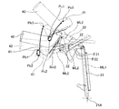
- the control device 70 has a support member 40 along the first movement locus Tb1-Tb3 and the second movement locus Tu1-Tu3 according to various standing start positions PRs1-PRs3.
- the control device 70 is a support member so that the first movement locus Tb1-Tb3 and the second movement locus Tu1-Tu3 are substantially the same position and angle at the end of the first step described later. Move 40.
- the control device 70 causes both the first arm 21 and the second arm 22 to turn forward or backward when adjusting the standing start position PRs.
- the control device 70 turns the first arm 21 forward and the second arm 22 backward, so that the person being assisted M is in a sitting posture and a standing position.
- the first step of shifting to an intermediate posture with the posture is performed. The details of the operation processing of the standing operation by the assistance device 1 will be described later.
- the controller 60 considers that there is an operation request (adjustment request or auxiliary request) only during the period when any of the buttons 61-64 is pressed. Further, when there is an operation request, the control device 70 may not execute the operation according to the request depending on the operating state of the assistance device 1. This is assumed, for example, when the posture of the person being assisted M is inappropriate for the movement of the support member 40 in response to the request, or when the movement of the support member 40 has reached the boundary of the movable range. To. As an example, as described above, there is a case where the control device 70 refuses to execute the adjustment of the standing start position PRs.
- the state before the execution of the operation process for assisting the standing operation of the person being assisted M is set as the initial state of the assisting device 1 (see FIG. 2).
- the initial state of the assistance device 1 the vertical position of the support member 40 is adjusted according to, for example, the physique of the person being assisted M and the height of the seat surface 91 of the chair 90.
- a standing support state a state in which the body support portion 41 of the support member 40 supports the body of the person being assisted M in a standing position from below.
- the first arm 21 is provided on the base 10 so as to be rotatable around the first central axis 21A.
- the first arm 21 passes through the first central axis 21A and the second central axis 22A so as to extend upward from the first central axis 21A in the initial state of the assistance device 1. It is formed in a linear shape along.
- the second arm 22 is formed so as to extend rearward from the second central axis 22A in the initial state of the assistance device 1.
- the first central axis 21A is located near the mounting position of the front wheel 16 in the front-rear direction and is located between the base 10 and the knee pad member 80 in the vertical direction. Is set to. Specifically, the first central axis 21A is set to a position lower than the knee flexion position PKb of the person being assisted. Further, the second central shaft 22A is located behind the first central shaft 21A in the initial state of the assistance device 1. That is, in the initial state, the first arm 21 is tilted backward with respect to the vertical axis in the stretching direction.
- the second central axis 22A is located in front of the knee flexion position PKb at which the thigh Mh and the lower leg Me of the person being assisted M bend in the initial state of the assist device 1. More specifically, in the present embodiment, as shown in FIG. 2, the above-mentioned "knee flexion position PKb" passes through the central portion of the thigh Mh of the person being assisted M at the start of assisting the standing motion. This is the intersection of the femur virtual line NL1 extending in the extension direction of the femur Mh and the lower leg virtual line NL2 extending in the extension direction of the lower leg Me through the central portion of the lower leg Me of the person being assisted M. As described above, the first arm 21 is configured such that the second central axis 22A is positioned forward of the knee flexion position PKb of the person being assisted M while tilting backward in the initial state of the assisting device 1.
- the second central shaft 22A may be located directly above the knee pad member 80 or in front of the knee pad member 80 in the initial state of the assist device 1. Further, as shown in FIGS. 4 and 7, the second central axis 22A is of the body support portion 41 in the standing support state in which the body support portion 41 supports the body of the person being assisted M in the standing posture. It may be located in front of the front end of the portion in contact with the fuselage.
- the first arm 21 and the second arm 22 are respectively configured so as to have a positional relationship between the first central shaft 21A and the second central shaft 22A as described above. Supplementally, the first arm 21 extends from the first central axis 21A to a height at which the chest Mb of the person being assisted M is located, and is tilted backward in the initial state of the assisting device 1.
- the second arm 22 secures a horizontal length from the second central axis 22A to the front surface of the support member 40 in contact with the chest Mb of the person being assisted M. Further, the second arm 22 is configured to extend obliquely backward from the second central shaft 22A to the connecting portion with the support member 40 in the standing support state of the assistance device 1.
- the support member 40 is sufficiently between the both legs Mg and the first arm 21 in a posture in which the person being assisted M is in contact with the chest. Space can be formed. As a result, it is possible to prevent the members other than the knee pad member 80 from interfering with both legs Mg of the person being assisted M while ensuring the position adjustable range of the knee pad member 80. Further, by ensuring the length of the second arm, the vertical direction of the support member 40 is reduced while reducing the amount of movement of the support member 40 in the front-rear direction in the adjustment of the standing start position PRs accompanied by the rotation of the second arm 22. It becomes easy to secure the movement amount of. Further, by securing the length of the second arm 22, as shown in FIG. 4, the support member 40 can be raised to a sufficient height together with the first arm 21 in the standing support state.
- the movable range Rm1 of the first arm 21 includes an angle in which the first virtual line ML1 passing through the first central axis 21A and the second central axis 22A is in the vertical direction. May be good.
- the movable range Rm1 of the first arm 21 is set to a range in which the first virtual line ML1 can turn back and forth by 25 degrees with respect to an angle corresponding to the vertical axis.
- the movable range Rm2 of the second arm 22 includes an angle in which the second virtual line ML2 passing through the reference position set on the second central axis 22A and the support member 40 is in the horizontal direction. May be made.
- the movable range Rm2 of the second arm 22 is set to a range in which the second virtual line ML2 can turn up and down by 25 degrees with respect to an angle corresponding to the horizontal axis.
- the lower reference position Pb and the upper reference position Pu can be set at the above reference position.
- the lower reference position Pb is set at the lower end of the body support portion 41 that comes into contact with the body.
- the upper reference position Pu is set at the upper end of the portion of the body support portion 41 that comes into contact with the body.
- the upper reference position Pu may be set to a position beside the person being assisted M.
- the supporting member 40 that swings with respect to the base 10. There may be a part that moves forward and a part that moves backward, and similarly, there may be a part that rises and a part that descends with respect to the base 10. Therefore, in the following, the movement of the reference position set to the position where the support member 40 is integrally moved will be described as the movement of the support member 40. As described above, the lower reference position Pb and the upper reference position Pu can be set at the reference position.
- Adjustment processing of standing start position PRs by the assistance device 1 Adjustment processing of the standing start position PRs by the assistance device 1 will be described with reference to FIGS. 5 and 6.
- the above-mentioned adjustment process of the standing start position PRs is executed, for example, when the ascending button 61 or the descending button 62 of the controller 60 is pressed, and the adjustment instructing unit 71 instructs the adjustment of the standing start position PRs of the support member 40.
- the control device 70 permits the execution of the adjustment of the standing start position PRs based on the operating state of the assistance device 1.
- the control device 70 drives the first actuator 31 and the second actuator 32 to extend when the support member 40 is raised.
- the first arm 21 swivels forward around the first central axis 21A
- the second arm 22 swivels forward around the second central shaft 22A in coordination with this.
- the standing start position PRs move upward along the adjustment movement locus Tj as shown in FIG.
- FIG. 6 shows the first reference locus Tr1 and the second reference locus Tr2 to be compared with the above-mentioned adjustment movement locus Tj when the standing start position PRs is set to the lower reference position Pb.
- the first reference locus Tr1 is a movement locus when the rotation of the second arm 22 is stopped and the adjustment of the standing start position PRs is attempted only by the rotation of the first arm 21.
- the second reference locus Tr2 is a movement locus when the rotation of the first arm 21 is stopped and the adjustment of the standing start position PRs is attempted only by the rotation of the second arm 22.
- the adjustment movement locus Tj can secure a sufficient vertical adjustable range while reducing the amount of movement in the front-rear direction as compared with the first reference locus Tr1. Further, although the adjustment movement locus Tj has a larger movement amount in the front-rear direction than the second reference locus Tr2, the tilt amount of the support member 40 before and after the movement in the adjustable range can be reduced. Further, while the second reference locus Tr2 has a portion that moves backward and a portion that moves forward in the adjustable range, the adjustment movement locus Tj monotonically moves the support member 40 forward, for example, when the support member 40 rises. Can be moved.
- the control device 70 drives the first actuator 31 and the second actuator 32 so as to shorten them.
- the first arm 21 rear-turns around the first central axis 21A
- the second arm 22 rear-turns around the second central axis 22A in coordination with this.
- the standing start position PRs move downward along the adjustment movement locus Tj.
- the control device 70 rejects the adjustment request to the ascending side or the adjusting request to the descending side, and stops the operation of the driving device 30.
- the operation processing of assisting the standing operation by the assistance device 1 will be described with reference to FIGS. 2-FIG. 4 and 7.
- the operation process of the standing operation includes a first step of moving the support member 40 forward and a second step of moving the support member 40 forward and raising the support member 40.
- the first step and the second step of the operation process are actually executed in a series, and when the support member 40 follows a smooth movement locus, it is not always possible to experience the change of steps.
- the step of advancing the support member 40 so that the mass of the upper body of the person being assisted M is generally deposited in the support member 40 is referred to as a first step.
- the first step includes an operation of rotating the second arm 22 backward in parallel with the front rotation of the first arm 21 at the initial stage of the standing operation.
- the person being assisted M shifts from the initial sitting posture shown in FIG. 2 to the intermediate posture in which the upper body is tilted forward as shown in FIG.
- the process of advancing and raising the support member 40 so as to raise the upper body of the person being assisted M is referred to as a second step.
- the person being assisted M shifts from the intermediate posture shown in FIG. 3 to the standing posture in which both legs Mg, which is the end state shown in FIG. 4, is extended.
- the person being assisted M is in a seated state (a sitting posture state) in which the buttocks Mt is in contact with the seat surface 91 of the chair 90. ..
- the assistance device 1 is set to the initial state of the operation process for assisting the standing operation by the operation by the person being assisted M or the assistant.
- the above operation includes adjusting the position of the assisting device 1 with respect to the person being assisted M, and adjusting the height of the support member 40 (adjusting the standing start position PRs) according to the physique and the like of the person being assisted M.
- the person being assisted M places both legs on the footrest table 12. At this time, the person being assisted M brings the front surface of the body into surface contact with the body support portion 41. In addition, the person being assisted M brings the knee into contact with the rear surface of the knee pad member 80. Further, the person being assisted M grips the first handle 51. At this time, depending on the physique of the person being assisted M, a certain gap may occur between the side of the person being assisted M and the side support portion 42. As described above, in the initial state in which the preparation for boarding the assist device 1 is completed, the person being assisted M is in a posture in which the upper body is tilted forward to some extent as shown in FIG.
- the control device 70 puts the person being assisted M in the initial sitting posture with the upper body forward. Perform the first step with a tilted intermediate posture. Specifically, in the first step, the control device 70 causes the first arm 21 to turn forward and the second arm 22 to turn backward. As a result, the control device 70 advances the support member 40 with respect to the base 10 and maintains or lowers the height of the support member 40 with respect to the base 10.
- the control device 70 turns the first arm 21 forward and turns the second arm 22 backward until the first arm 21 reaches a predetermined angle. At this time, for example, if the second arm 22 reaches the rearmost turning end of the movable range Rm2 before the first arm 21 reaches the specified angle, the control device 70 will move the second arm 22 to the second arm 22. (2) The first arm 21 is swiveled forward with the swivel around the central axis 22A stopped. Further, when the first arm 21 reaches the specified angle, the control device 70 ends the first step, assuming that the person being assisted M has shifted to the intermediate posture.
- the motion of bending the lumbar region so as to shift from the sitting posture to the intermediate posture as the first step of the standing posture is close to the motion of the person being assisted M bending the lumbar region and depositing the weight on the support member 40, which is natural. It is an operation.
- the control device 70 turns both the first arm 21 and the second arm 22 forward to change the person being assisted M from the intermediate posture to the standing posture. Perform the process. Specifically, the control device 70 continues the forward turning of the first arm 21, and switches the operation of the second arm 22 from the rear turning or the stopped state to the front turning.
- the control device 70 maintains the front turning of the first arm 21 until the first arm 21 reaches the turning end on the front side of the movable range Rm1, and the second arm 22 turns the front side of the movable range Rm2.
- the forward turn of the second arm 22 is maintained until it reaches the end.
- the control device 70 uses the first arm so that the lower reference position Tb of the support member 40 moves along different movement loci according to the standing start position PRs adjusted in advance. 21 and the second arm 22 are operated in cooperation. Specifically, as shown in FIG. 5, when the standing start position PRs are adjusted to three types of standing start positions PRs1-PRs3, the control device 70 has three types of lower reference positions Pb corresponding to these. The support member 40 is moved along the first movement locus Tb1-Tb3.
- the control device 70 moves the support member 40 so that the upper reference position Pu follows the three types of second movement loci Tu1-Tu3 corresponding to the three types of standing start positions PRs1-PRs3.
- the control device 70 moves the support member 40 so as to have substantially the same position and angle at the end of the first step regardless of which movement locus the support member 40 is moved.
- the position and angle of the support member 40 are the adjusted standing start position PRs, the specified angle of the first arm 21 in the first step, and the arms 21 and 22 respectively. It may fluctuate depending on the movable range of.
- the position where the lower reference position Pb arrives at the end of the second step can be appropriately changed on the first movement locus Tb.
- the control device 70 ends the operation process of the standing operation when the assistance request is no longer input to the assistance device 1. Therefore, depending on the lower reference position Pb at the end, the assisted person M in the standing posture may be in a state in which, for example, the knee does not come into contact with the knee pad member 80, in addition to the posture shown in FIG. This also applies to the upper reference position Pu.
- the control device 70 of the assistance device 1 of the embodiment cooperates with the first arm 21 and the second arm 22 so that the support member 40 moves in the vertical direction when the instruction of the adjustment instruction unit 71 is received. Let me. Further, when the control device 70 receives an instruction from the standing operation instruction unit 72, the reference position of the support member 40 moves along different movement loci Tb, Tu according to the standing start position adjusted by the instruction of the adjustment instruction unit 71. The first arm 21 and the second arm 22 are operated in cooperation with each other.
- the support member 40 is moved along the predetermined movement trajectories Td and Tu by the first arm 21 and the second arm 22 that form a mechanism having two joints with respect to the base 10. Can be made to.
- the assistance device 1 can move the support member 40 in the vertical direction in response to the adjustment instruction to adjust the standing start position PRs. Further, the assistance device 1 moves the support member 40 along different movement loci Tb and Tu according to the adjusted standing start position PRs. As a result, the person being assisted M can shift from the sitting posture to the standing posture with a more natural movement.
- the reference position is set at the lower end, the upper end, or the side of the person being assisted M in the body support portion 41 in contact with the body of the person being assisted M. ..
- the reference position can be appropriately set as long as it is set to a position where it moves integrally with the support member 40.
- the reference position may be set at the position of the chest Mb of the person being assisted M in the configuration in which the support member 40 includes the body support portion as illustrated in the embodiment.
- the reference position may be set at the connecting portion between the support member 40 and the second arm 22. Even in such a configuration, the same effect as that of the embodiment is obtained.
- the motion processing of the standing motion is composed of two steps, a first step and a second step, which are executed in a series.
- another step may be appropriately included in the operation process of the standing operation.
- the operation process may include a preparatory step for changing the assisting device 1 from the current state to the initial state, a recovery step when each step once executed is stopped and then restarted.
- the control device 70 combines various steps based on the operating state of the assisting device 1 and the input auxiliary request or adjustment request to coordinately support the turning of the first arm 21 and the turning of the second arm 22. It may be configured to control the movement of the member 40.
- the first step and the second step are defined as described above, but in addition, the angles of the first arm 21 and the second arm 22, the position of the lower reference position Pb in the first movement locus Tb, and the second movement.
- the process may be divided according to the position of the upper reference position Pu in the locus Tu, the angle of the support member 40, the posture of the person being assisted M, and the like.
- the first arm 22 in the process of shifting from the sitting posture to the intermediate posture, the first arm 22 is swiveled backward (stopped when reaching the swivel end on the rear side of the movable range Rm2). By turning 21 forward, the same effect as that of the embodiment is obtained.
- Assistance device 10: Base, 21: First arm, 22: Second arm, 21A: First central axis, 22A: Second central axis, 30: Drive device, 31: First actuator, 32: No. Two actuators, 40: Support member, 41: Body support, 42: Side support, 60: Controller, 61: Up button, 62: Down button, 63: Standing button, 64: Seating button, 70: Control device, 71 : Adjustment instruction part, 72: Standing motion instruction part, 80: Knee pad member, M: Assisted person, Mt: Butt, Mg: Both legs, Mh: Thigh Mh, Me: Lower leg, NL1: Thigh virtual line , NL2: lower leg virtual line, ML1: first virtual line, ML2: second virtual line, Rm1, Rm2: movable range, PKb: knee flexion position, Pb, Pu: reference position, PRs: standing start position,
Landscapes
- Health & Medical Sciences (AREA)
- Life Sciences & Earth Sciences (AREA)
- Animal Behavior & Ethology (AREA)
- General Health & Medical Sciences (AREA)
- Public Health (AREA)
- Veterinary Medicine (AREA)
- Nursing (AREA)
- Invalid Beds And Related Equipment (AREA)
- Rehabilitation Tools (AREA)
- Manipulator (AREA)
Abstract
Priority Applications (7)
| Application Number | Priority Date | Filing Date | Title |
|---|---|---|---|
| KR1020207029525A KR102518666B1 (ko) | 2019-04-12 | 2019-04-12 | 시중 장치 |
| CA3136298A CA3136298C (fr) | 2019-04-12 | 2019-04-12 | Dispositif de soin pour offrir de l'aide dans une activite de levage |
| DE112019007196.3T DE112019007196T5 (de) | 2019-04-12 | 2019-04-12 | Pflegevorrichtung |
| JP2021513152A JP7121189B2 (ja) | 2019-04-12 | 2019-04-12 | 介助装置 |
| CN201980025854.6A CN112087993B (zh) | 2019-04-12 | 2019-04-12 | 护理装置 |
| PCT/JP2019/016065 WO2020208832A1 (fr) | 2019-04-12 | 2019-04-12 | Dispositif de prise en charge |
| US17/601,714 US12127987B2 (en) | 2019-04-12 | 2019-04-12 | Caring device |
Applications Claiming Priority (1)
| Application Number | Priority Date | Filing Date | Title |
|---|---|---|---|
| PCT/JP2019/016065 WO2020208832A1 (fr) | 2019-04-12 | 2019-04-12 | Dispositif de prise en charge |
Publications (1)
| Publication Number | Publication Date |
|---|---|
| WO2020208832A1 true WO2020208832A1 (fr) | 2020-10-15 |
Family
ID=72751084
Family Applications (1)
| Application Number | Title | Priority Date | Filing Date |
|---|---|---|---|
| PCT/JP2019/016065 Ceased WO2020208832A1 (fr) | 2019-04-12 | 2019-04-12 | Dispositif de prise en charge |
Country Status (7)
| Country | Link |
|---|---|
| US (1) | US12127987B2 (fr) |
| JP (1) | JP7121189B2 (fr) |
| KR (1) | KR102518666B1 (fr) |
| CN (1) | CN112087993B (fr) |
| CA (1) | CA3136298C (fr) |
| DE (1) | DE112019007196T5 (fr) |
| WO (1) | WO2020208832A1 (fr) |
Families Citing this family (4)
| Publication number | Priority date | Publication date | Assignee | Title |
|---|---|---|---|---|
| JP7451417B2 (ja) * | 2018-10-04 | 2024-03-18 | 株式会社Fuji | 介助装置 |
| WO2021131185A1 (fr) * | 2019-12-25 | 2021-07-01 | 株式会社がまかつ | Dispositif d'assistance |
| CN114795708B (zh) * | 2022-04-28 | 2023-04-28 | 北京邮电大学 | 一种辅助站立设备 |
| CN220125053U (zh) * | 2023-05-31 | 2023-12-05 | 杨先和 | 具有大前轮小后轮的四轮助行器 |
Citations (3)
| Publication number | Priority date | Publication date | Assignee | Title |
|---|---|---|---|---|
| JP2011110080A (ja) * | 2009-11-24 | 2011-06-09 | Toyota Motor Corp | 移乗支援装置 |
| JP2015139566A (ja) * | 2014-01-29 | 2015-08-03 | トヨタ自動車株式会社 | 介護支援装置 |
| WO2018163307A1 (fr) * | 2017-03-07 | 2018-09-13 | 株式会社Fuji | Dispositif d'assistance |
Family Cites Families (42)
| Publication number | Priority date | Publication date | Assignee | Title |
|---|---|---|---|---|
| US5001789A (en) * | 1989-12-05 | 1991-03-26 | Schoenberger Luther V | Invalid lift and transport apparatus |
| US5117516A (en) * | 1991-11-25 | 1992-06-02 | Elmer Penner | Patient sling |
| GB9126689D0 (en) * | 1991-12-17 | 1992-02-12 | Parker Roy | Invalid hoists |
| US5411044A (en) * | 1994-04-12 | 1995-05-02 | Andolfi; Alexander S. | Patient transfer walker |
| US6119287A (en) * | 1998-05-29 | 2000-09-19 | Phillips; Barry S. | Lift and transfer apparatus for a disabled person |
| GB0004795D0 (en) * | 2000-03-01 | 2000-04-19 | Helping Hand Co Ledbury | Improvements relating to patient carrying platforms |
| US6806430B2 (en) * | 2001-04-23 | 2004-10-19 | Ez Way, Inc. | Patient lift and scale |
| CN101069661A (zh) * | 2007-06-15 | 2007-11-14 | 大连北柳咨询服务有限公司 | 起立·移动辅助装置 |
| US7921486B2 (en) * | 2007-12-27 | 2011-04-12 | Joerns Healthcare, Llc | Multi-position support for a folding patient lift device |
| US7921485B2 (en) * | 2007-12-27 | 2011-04-12 | Joerns Healthcare, Llc | Folding patient lift device |
| NL2001474C2 (nl) * | 2008-04-11 | 2009-10-13 | Joyincare Group B V | Kleminrichting ten gebruike in een tillift voor het verplaatsen van personen. |
| CA2730354C (fr) * | 2008-08-07 | 2015-02-10 | Invacare Corporation | Leve-malade muni d'appuis reglables pour genoux et de crochets de levage |
| US8060958B1 (en) * | 2009-06-08 | 2011-11-22 | Randall Hough | Powered person lift and transport apparatus |
| US8832874B2 (en) * | 2009-06-29 | 2014-09-16 | Keith Vivian Alexander | Person moving devices for moving persons of limited mobility |
| JP5460154B2 (ja) | 2009-07-13 | 2014-04-02 | 富士機械製造株式会社 | 歩行介助装置 |
| KR101443927B1 (ko) | 2009-08-20 | 2014-09-25 | (주)아모레퍼시픽 | 헥사미딘류 및 레티노이드류를 함유하는 피부 개선 조성물 |
| JP5556903B2 (ja) * | 2010-12-28 | 2014-07-23 | トヨタ自動車株式会社 | 移乗支援装置及びその作動方法 |
| WO2013015059A1 (fr) * | 2011-07-27 | 2013-01-31 | 株式会社鍛錬 | Outil de déplacement |
| WO2013028961A1 (fr) * | 2011-08-24 | 2013-02-28 | Hill-Rom Services, Inc. | Aide au redressement de patients, dispositifs de thérapie et procédés |
| JP5921228B2 (ja) | 2012-02-02 | 2016-05-24 | 富士機械製造株式会社 | 起立動作支援ロボット |
| US10166159B2 (en) * | 2013-02-07 | 2019-01-01 | Fuji Corporation | Care robot |
| DK177674B1 (en) * | 2013-03-26 | 2014-02-17 | Revac Aps | Apparatus and approach to assist persons with disabilities or persons with disabilities |
| EP3025695B1 (fr) * | 2013-07-26 | 2018-04-04 | Fuji Machine Mfg. Co., Ltd. | Robot d'assistance |
| US10125313B2 (en) | 2014-02-03 | 2018-11-13 | Ube Industries, Ltd. | Oxynitride phosphor powder and method for producing same |
| EP3123995B1 (fr) * | 2014-03-28 | 2024-07-17 | FUJI Corporation | Robot d'assistance |
| US9844481B2 (en) * | 2015-07-13 | 2017-12-19 | Panasonic Intellectual Property Management Co., Ltd. | Standing/sitting motion assist system, standing/sitting motion assist method, standing/sitting motion assist robot, and non-transitory computer-readable recording medium |
| CN205263661U (zh) * | 2015-11-16 | 2016-05-25 | 哈尔滨工大天才智能科技有限公司 | 一种辅助站立机器人控制系统 |
| JP2017148425A (ja) | 2016-02-26 | 2017-08-31 | トヨタ自動車株式会社 | 移乗装置及びその制御方法 |
| CN206482744U (zh) * | 2016-08-24 | 2017-09-12 | 上海邦邦机器人有限公司 | 一种手起式站立轮椅车 |
| JP6712641B2 (ja) * | 2016-09-13 | 2020-06-24 | 株式会社Fuji | 介助装置 |
| JP6700426B2 (ja) | 2016-12-22 | 2020-05-27 | 株式会社Fuji | 介助装置 |
| WO2018167856A1 (fr) | 2017-03-14 | 2018-09-20 | 株式会社Fuji | Dispositif d'aide |
| CN107088128B (zh) * | 2017-05-03 | 2019-03-19 | 河北工业大学 | 一种移乘护理机器人的行为安全控制方法 |
| CN107693234A (zh) * | 2017-11-09 | 2018-02-16 | 杭州程天科技发展有限公司 | 一种麦克纳姆轮驱动的全向助行车 |
| JP7451417B2 (ja) * | 2018-10-04 | 2024-03-18 | 株式会社Fuji | 介助装置 |
| TWI719352B (zh) * | 2018-10-29 | 2021-02-21 | 緯創資通股份有限公司 | 助行器 |
| KR102471825B1 (ko) * | 2019-04-12 | 2022-11-28 | 가부시키가이샤 후지 | 시중 장치 |
| JP7213999B2 (ja) * | 2019-09-12 | 2023-01-27 | 株式会社Fuji | 介助装置 |
| JP7587800B2 (ja) | 2019-10-19 | 2024-11-21 | 学校法人関西学院 | 起立着座動作支援装置および起立着座動作支援方法 |
| JP7601742B2 (ja) * | 2021-10-22 | 2024-12-17 | 本田技研工業株式会社 | 立ち上がり補助機 |
| JP7629381B2 (ja) * | 2021-10-22 | 2025-02-13 | 本田技研工業株式会社 | 立ち上がり補助機 |
| JP7601743B2 (ja) * | 2021-10-22 | 2024-12-17 | 本田技研工業株式会社 | 立ち上がり補助機 |
-
2019
- 2019-04-12 WO PCT/JP2019/016065 patent/WO2020208832A1/fr not_active Ceased
- 2019-04-12 DE DE112019007196.3T patent/DE112019007196T5/de active Pending
- 2019-04-12 KR KR1020207029525A patent/KR102518666B1/ko active Active
- 2019-04-12 CA CA3136298A patent/CA3136298C/fr active Active
- 2019-04-12 US US17/601,714 patent/US12127987B2/en active Active
- 2019-04-12 JP JP2021513152A patent/JP7121189B2/ja active Active
- 2019-04-12 CN CN201980025854.6A patent/CN112087993B/zh active Active
Patent Citations (3)
| Publication number | Priority date | Publication date | Assignee | Title |
|---|---|---|---|---|
| JP2011110080A (ja) * | 2009-11-24 | 2011-06-09 | Toyota Motor Corp | 移乗支援装置 |
| JP2015139566A (ja) * | 2014-01-29 | 2015-08-03 | トヨタ自動車株式会社 | 介護支援装置 |
| WO2018163307A1 (fr) * | 2017-03-07 | 2018-09-13 | 株式会社Fuji | Dispositif d'assistance |
Also Published As
| Publication number | Publication date |
|---|---|
| KR20200131879A (ko) | 2020-11-24 |
| CA3136298C (fr) | 2024-05-14 |
| JPWO2020208832A1 (ja) | 2021-12-09 |
| KR102518666B1 (ko) | 2023-04-05 |
| JP7121189B2 (ja) | 2022-08-17 |
| CA3136298A1 (fr) | 2020-10-15 |
| US12127987B2 (en) | 2024-10-29 |
| CN112087993A (zh) | 2020-12-15 |
| US20220192908A1 (en) | 2022-06-23 |
| CN112087993B (zh) | 2022-09-13 |
| DE112019007196T5 (de) | 2021-12-23 |
Similar Documents
| Publication | Publication Date | Title |
|---|---|---|
| JP7121189B2 (ja) | 介助装置 | |
| JP6700426B2 (ja) | 介助装置 | |
| JP7007912B2 (ja) | 介助装置 | |
| WO2020208831A1 (fr) | Appareil d'assistance | |
| JP6636057B2 (ja) | 介助ロボット | |
| WO2017141336A1 (fr) | Robot d'assistance | |
| JP7011084B2 (ja) | 介助装置 | |
| HK40071488A (en) | Assistive apparatus | |
| HK40033422A (en) | Caring device | |
| JP6709297B2 (ja) | 介助装置 | |
| HK40033422B (en) | Caring device | |
| HK40033421B (en) | Assistive apparatus | |
| HK40033421A (en) | Assistive apparatus | |
| JP6709323B2 (ja) | 介助装置 | |
| JPWO2018116473A1 (ja) | 介助装置 | |
| CN121714437A (zh) | 按摩机机架、按摩机及按摩机的控制方法 | |
| HK40071488B (zh) | 护理装置 | |
| JP2020168536A (ja) | 介助ロボット | |
| WO2018116475A1 (fr) | Dispositif d'assistance |
Legal Events
| Date | Code | Title | Description |
|---|---|---|---|
| ENP | Entry into the national phase |
Ref document number: 20207029525 Country of ref document: KR Kind code of ref document: A |
|
| 121 | Ep: the epo has been informed by wipo that ep was designated in this application |
Ref document number: 19923779 Country of ref document: EP Kind code of ref document: A1 |
|
| ENP | Entry into the national phase |
Ref document number: 2021513152 Country of ref document: JP Kind code of ref document: A |
|
| ENP | Entry into the national phase |
Ref document number: 3136298 Country of ref document: CA |
|
| 122 | Ep: pct application non-entry in european phase |
Ref document number: 19923779 Country of ref document: EP Kind code of ref document: A1 |