WO2020208926A1 - 信号処理装置、信号処理方法及びプログラム - Google Patents
信号処理装置、信号処理方法及びプログラム Download PDFInfo
- Publication number
- WO2020208926A1 WO2020208926A1 PCT/JP2020/005061 JP2020005061W WO2020208926A1 WO 2020208926 A1 WO2020208926 A1 WO 2020208926A1 JP 2020005061 W JP2020005061 W JP 2020005061W WO 2020208926 A1 WO2020208926 A1 WO 2020208926A1
- Authority
- WO
- WIPO (PCT)
- Prior art keywords
- sound
- signal
- unit
- microphone
- target sound
- Prior art date
- Legal status (The legal status is an assumption and is not a legal conclusion. Google has not performed a legal analysis and makes no representation as to the accuracy of the status listed.)
- Ceased
Links
Images









Classifications
-
- G—PHYSICS
- G10—MUSICAL INSTRUMENTS; ACOUSTICS
- G10L—SPEECH ANALYSIS TECHNIQUES OR SPEECH SYNTHESIS; SPEECH RECOGNITION; SPEECH OR VOICE PROCESSING TECHNIQUES; SPEECH OR AUDIO CODING OR DECODING
- G10L21/00—Speech or voice signal processing techniques to produce another audible or non-audible signal, e.g. visual or tactile, in order to modify its quality or its intelligibility
- G10L21/02—Speech enhancement, e.g. noise reduction or echo cancellation
- G10L21/0272—Voice signal separating
-
- G—PHYSICS
- G10—MUSICAL INSTRUMENTS; ACOUSTICS
- G10L—SPEECH ANALYSIS TECHNIQUES OR SPEECH SYNTHESIS; SPEECH RECOGNITION; SPEECH OR VOICE PROCESSING TECHNIQUES; SPEECH OR AUDIO CODING OR DECODING
- G10L15/00—Speech recognition
- G10L15/08—Speech classification or search
- G10L15/083—Recognition networks
-
- G—PHYSICS
- G10—MUSICAL INSTRUMENTS; ACOUSTICS
- G10L—SPEECH ANALYSIS TECHNIQUES OR SPEECH SYNTHESIS; SPEECH RECOGNITION; SPEECH OR VOICE PROCESSING TECHNIQUES; SPEECH OR AUDIO CODING OR DECODING
- G10L15/00—Speech recognition
- G10L15/20—Speech recognition techniques specially adapted for robustness in adverse environments, e.g. in noise, of stress induced speech
-
- G—PHYSICS
- G10—MUSICAL INSTRUMENTS; ACOUSTICS
- G10L—SPEECH ANALYSIS TECHNIQUES OR SPEECH SYNTHESIS; SPEECH RECOGNITION; SPEECH OR VOICE PROCESSING TECHNIQUES; SPEECH OR AUDIO CODING OR DECODING
- G10L21/00—Speech or voice signal processing techniques to produce another audible or non-audible signal, e.g. visual or tactile, in order to modify its quality or its intelligibility
- G10L21/02—Speech enhancement, e.g. noise reduction or echo cancellation
- G10L21/0208—Noise filtering
- G10L21/0216—Noise filtering characterised by the method used for estimating noise
- G10L21/0224—Processing in the time domain
-
- G—PHYSICS
- G10—MUSICAL INSTRUMENTS; ACOUSTICS
- G10L—SPEECH ANALYSIS TECHNIQUES OR SPEECH SYNTHESIS; SPEECH RECOGNITION; SPEECH OR VOICE PROCESSING TECHNIQUES; SPEECH OR AUDIO CODING OR DECODING
- G10L25/00—Speech or voice analysis techniques not restricted to a single one of groups G10L15/00 - G10L21/00
- G10L25/78—Detection of presence or absence of voice signals
- G10L25/84—Detection of presence or absence of voice signals for discriminating voice from noise
-
- H—ELECTRICITY
- H04—ELECTRIC COMMUNICATION TECHNIQUE
- H04R—LOUDSPEAKERS, MICROPHONES, GRAMOPHONE PICK-UPS OR LIKE ACOUSTIC ELECTROMECHANICAL TRANSDUCERS; ELECTRIC HEARING AIDS; PUBLIC ADDRESS SYSTEMS
- H04R1/00—Details of transducers, loudspeakers or microphones
- H04R1/10—Earpieces; Attachments therefor ; Earphones; Monophonic headphones
-
- H—ELECTRICITY
- H04—ELECTRIC COMMUNICATION TECHNIQUE
- H04R—LOUDSPEAKERS, MICROPHONES, GRAMOPHONE PICK-UPS OR LIKE ACOUSTIC ELECTROMECHANICAL TRANSDUCERS; ELECTRIC HEARING AIDS; PUBLIC ADDRESS SYSTEMS
- H04R3/00—Circuits for transducers
-
- H—ELECTRICITY
- H04—ELECTRIC COMMUNICATION TECHNIQUE
- H04R—LOUDSPEAKERS, MICROPHONES, GRAMOPHONE PICK-UPS OR LIKE ACOUSTIC ELECTROMECHANICAL TRANSDUCERS; ELECTRIC HEARING AIDS; PUBLIC ADDRESS SYSTEMS
- H04R3/00—Circuits for transducers
- H04R3/005—Circuits for transducers for combining the signals of two or more microphones
-
- G—PHYSICS
- G10—MUSICAL INSTRUMENTS; ACOUSTICS
- G10L—SPEECH ANALYSIS TECHNIQUES OR SPEECH SYNTHESIS; SPEECH RECOGNITION; SPEECH OR VOICE PROCESSING TECHNIQUES; SPEECH OR AUDIO CODING OR DECODING
- G10L15/00—Speech recognition
- G10L15/08—Speech classification or search
- G10L2015/088—Word spotting
-
- G—PHYSICS
- G10—MUSICAL INSTRUMENTS; ACOUSTICS
- G10L—SPEECH ANALYSIS TECHNIQUES OR SPEECH SYNTHESIS; SPEECH RECOGNITION; SPEECH OR VOICE PROCESSING TECHNIQUES; SPEECH OR AUDIO CODING OR DECODING
- G10L21/00—Speech or voice signal processing techniques to produce another audible or non-audible signal, e.g. visual or tactile, in order to modify its quality or its intelligibility
- G10L21/02—Speech enhancement, e.g. noise reduction or echo cancellation
- G10L21/0208—Noise filtering
- G10L21/0216—Noise filtering characterised by the method used for estimating noise
- G10L2021/02161—Number of inputs available containing the signal or the noise to be suppressed
- G10L2021/02165—Two microphones, one receiving mainly the noise signal and the other one mainly the speech signal
-
- H—ELECTRICITY
- H04—ELECTRIC COMMUNICATION TECHNIQUE
- H04R—LOUDSPEAKERS, MICROPHONES, GRAMOPHONE PICK-UPS OR LIKE ACOUSTIC ELECTROMECHANICAL TRANSDUCERS; ELECTRIC HEARING AIDS; PUBLIC ADDRESS SYSTEMS
- H04R23/00—Transducers other than those covered by groups H04R9/00 - H04R21/00
- H04R23/008—Transducers other than those covered by groups H04R9/00 - H04R21/00 using optical signals for detecting or generating sound
-
- H—ELECTRICITY
- H04—ELECTRIC COMMUNICATION TECHNIQUE
- H04R—LOUDSPEAKERS, MICROPHONES, GRAMOPHONE PICK-UPS OR LIKE ACOUSTIC ELECTROMECHANICAL TRANSDUCERS; ELECTRIC HEARING AIDS; PUBLIC ADDRESS SYSTEMS
- H04R2410/00—Microphones
- H04R2410/05—Noise reduction with a separate noise microphone
-
- H—ELECTRICITY
- H04—ELECTRIC COMMUNICATION TECHNIQUE
- H04R—LOUDSPEAKERS, MICROPHONES, GRAMOPHONE PICK-UPS OR LIKE ACOUSTIC ELECTROMECHANICAL TRANSDUCERS; ELECTRIC HEARING AIDS; PUBLIC ADDRESS SYSTEMS
- H04R2460/00—Details of hearing devices, i.e. of ear- or headphones covered by H04R1/10 or H04R5/033 but not provided for in any of their subgroups, or of hearing aids covered by H04R25/00 but not provided for in any of its subgroups
- H04R2460/13—Hearing devices using bone conduction transducers
Definitions
- the present disclosure relates to signal processing devices, signal processing methods and programs.
- a sound to be extracted (hereinafter, appropriately referred to as a target sound) can be appropriately extracted from a mixed sound in which a target sound and a sound other than the target sound are mixed.
- the present disclosure has been made in view of the above points, and is a signal processing device, a signal processing method, and a program capable of appropriately extracting a target sound from a mixed sound in which a target sound and a sound other than the target sound are mixed. Regarding.
- the present disclosure is, for example, An input unit for inputting a microphone signal including a mixed sound in which a target sound and a sound other than the target sound are mixed, and a one-dimensional time series signal synchronized with the target sound acquired by an auxiliary sensor. It is a signal processing device having a sound source extraction unit that extracts a target sound signal corresponding to a target sound from a microphone signal based on a one-dimensional time-series signal.
- the present disclosure includes, for example, A microphone signal including a mixed sound in which a target sound and a sound other than the target sound are mixed and a one-dimensional time series signal synchronized with the target sound acquired by an auxiliary sensor are input to the input unit.
- a microphone signal including a mixed sound in which a target sound and a sound other than the target sound are mixed and a one-dimensional time series signal synchronized with the target sound acquired by an auxiliary sensor are input to the input unit.
- This is a signal processing method in which a target sound signal corresponding to a target sound is extracted from a microphone signal by a sound source extraction unit based on a one-dimensional time-series signal.
- the present disclosure includes, for example, A microphone signal including a mixed sound in which a target sound and a sound other than the target sound are mixed and a one-dimensional time series signal synchronized with the target sound acquired by an auxiliary sensor are input to the input unit.
- This is a program that causes a computer to execute a signal processing method in which a target sound signal corresponding to a target sound is extracted from a microphone signal by a sound source extraction unit based on a one-dimensional time-series signal.
- FIG. 1 is a diagram for explaining a configuration example of a signal processing system according to an embodiment.
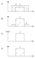
- 2A to 2D are diagrams referred to when the outline of the processing performed by the signal processing apparatus according to the embodiment is described.
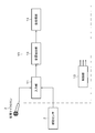
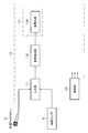
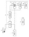
- FIG. 3 is a diagram for explaining a configuration example of the signal processing device according to the embodiment.
- FIG. 4 is a diagram for explaining one aspect of the signal processing device according to the embodiment.
- FIG. 5 is a diagram for explaining another aspect of the signal processing device according to the embodiment.
- FIG. 6 is a diagram for explaining another aspect of the signal processing device according to the embodiment.
- FIG. 7 is a diagram for explaining a detailed configuration example of the sound source extraction unit according to the embodiment.
- FIG. 8 is a diagram for explaining a detailed configuration example of the feature amount generation unit according to the embodiment.
- FIG. 10 is a diagram for explaining a detailed configuration example of the extraction model unit according to the embodiment.
- FIG. 11 is a diagram for explaining a detailed configuration example of the reconstruction unit according to the embodiment.
- FIG. 12 is a diagram referred to when explaining the learning system according to the embodiment.
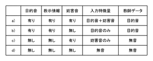
- FIG. 13 is a diagram showing learning data according to the embodiment.
- FIG. 14 is a diagram referred to when explaining a specific example of the air conduction microphone and the auxiliary sensor according to the embodiment.
- FIG. 15 is a diagram referred to when explaining other specific examples of the air conduction microphone and the auxiliary sensor according to the embodiment.
- FIG. 10 is a diagram for explaining a detailed configuration example of the extraction model unit according to the embodiment.
- FIG. 11 is a diagram for explaining a detailed configuration example of the reconstruction unit according to the embodiment.
- FIG. 12 is a diagram referred to when explaining the learning system according to the embodiment.
- FIG. 13 is a diagram showing learning data according to the embodiment.
- FIG. 14 is a diagram
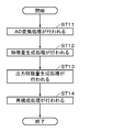
- FIG. 16 is a flowchart showing the flow of the entire processing performed by the signal processing apparatus according to the embodiment.
- FIG. 17 is a flowchart showing a flow of processing performed by the sound source extraction unit according to the embodiment.
- FIG. 18 is a diagram referred to when explaining a modified example.
- FIG. 19 is a diagram referred to when explaining a modified example.
- FIG. 20 is a diagram referred to when explaining a modified example.
- FIG. 21 is a diagram referred to when explaining a modified example.
- FIG. 22 is a diagram referred to when explaining a modified example.
- the present disclosure is a kind of sound source extraction with instruction, and includes a sensor (auxiliary sensor) for acquiring instruction information in addition to a microphone (air conduction microphone) for acquiring mixed sounds.
- a sensor auxiliary sensor
- the auxiliary sensor any one of the following or a combination of two or more can be considered.
- Another air-conducting microphone installed (mounted) in a position where the target sound can be obtained in a state where the target sound is predominant over the disturbing sound, such as the external auditory canal, (2) Bone conduction microphone, pharyngeal microphone, etc., other than in the atmosphere
- a microphone that acquires sound waves propagating through a microphone and (3) a sensor that acquires a signal that is modal other than sound and is synchronized with the user's speech.
- the auxiliary sensor is attached to, for example, the source of the target sound.
- vibration of the skin near the cheeks and throat, movement of muscles near the face, and the like can be considered as signals synchronized with the user's utterance. Specific examples of auxiliary sensors that acquire them will be described later.
- FIG. 1 shows a signal processing system (signal processing system 1) according to the embodiment of the present disclosure.
- the signal processing system 1 has a signal processing device 10.
- the signal processing device 10 generally includes an input unit 11 and a sound source extraction unit 12. Further, the signal processing system 1 has an air conduction microphone 2 for collecting sound and an auxiliary sensor 3.
- the air conduction microphone 2 and the auxiliary sensor 3 are connected to the input unit 11 of the signal processing device 10.
- the air conduction microphone 2 and the auxiliary sensor 3 are connected to the input unit 11 by wire or wirelessly.
- the auxiliary sensor 3 is, for example, a sensor attached to the source of the target sound.
- the auxiliary sensor 3 in this example is arranged in the vicinity of the user UA, and specifically, is attached to the body of the user UA.
- the auxiliary sensor 3 acquires a one-dimensional time-series signal synchronized with the target sound described later. Teaching information can be obtained based on such a time series signal.
- the target sound to be extracted by the sound source extraction unit 12 in the signal processing system 1 is a voice uttered by the user UA.
- the target sound is always a voice and is a directional sound source.
- the disturbing sound source is a sound source that emits a disturbing sound other than the target sound. This can be audio or non-audio, and both signals can come from the same source.
- the disturbing sound source is a directional sound source or an omnidirectional sound source.
- the number of disturbing sound sources is 0 or an integer of 1 or more. In the example shown in FIG. 1, a voice uttered by the user UB is shown as an example of the disturbing sound.
- the air conduction microphone 2 is a microphone that records sounds transmitted through the atmosphere, and acquires a mixed sound of a target sound and an interfering sound.
- the acquired mixed sound is appropriately referred to as a microphone observation signal.
- FIGS. 2A to 2D the horizontal axis represents time and the vertical axis represents volume (or power).
- FIG. 2A is an image diagram of a microphone observation signal.
- the microphone observation signal is a signal in which a component 4A derived from the target sound and a component 4B derived from the disturbing sound are mixed.
- FIG. 2B is an image diagram of teaching information.
- the auxiliary sensor 3 is another air-conducting microphone installed at a position different from that of the air-conducting microphone 2. Therefore, the one-dimensional time-series signal acquired by the auxiliary sensor 3 is a sound signal. Such a sound signal is used as teaching information.
- FIG. 2B is similar to FIG. 1 in that the target sound and the disturbing sound are mixed, but since the mounting position of the auxiliary sensor 3 is mounted on the user's body, it is more than the component 4B derived from the disturbing sound. The component 4A derived from the target sound is observed in a predominant state.
- FIG. 2C is another image diagram of the teaching information.
- the auxiliary sensor 3 is a sensor other than the air conduction microphone.
- signals acquired by sensors other than air conduction microphones include sound waves propagating in the user's body, which are acquired by bone conduction microphones and pharyngeal microphones, and the user's cheeks and throat, which are acquired by sensors other than microphones.
- vibrations of the skin surface such as, and myoelectric potential and acceleration of muscles near the mouth. Since these signals do not propagate in the atmosphere, they are considered to be less susceptible to disturbing sounds. Therefore, the teaching information is mainly composed of the component 4A derived from the target sound. That is, the signal strength rises when the user starts speaking, and falls when the user finishes speaking.
- the rising and falling timings of the component 4A derived from the target sound and the component 4B derived from the target sound are the same as those of the component 4A derived from the target sound. Is.
- the sound source extraction unit 12 of the signal processing device 10 inputs the microphone observation signal derived from the air conduction microphone 2 and the teaching information derived from the auxiliary sensor 3, and extracts the component derived from the disturbing sound from the microphone observation signal.
- the extraction result is generated by erasing and leaving the component derived from the target sound.
- FIG. 2D is an image of the extraction result.
- the ideal extraction result is composed only of the component 4A derived from the target sound.
- the sound source extraction unit 12 has a model showing the correspondence between the microphone observation signal and the teaching information to the extraction result. Such a model is pre-trained with a large amount of data.
- FIG. 3 is a diagram for explaining a configuration example of the signal processing device 10 according to the embodiment.
- the air conduction microphone 2 observes a mixed sound in which a target sound transmitted through the atmosphere and a sound other than the target sound (interfering sound) are mixed.
- the auxiliary sensor 3 is attached to the user's body and acquires a one-dimensional time-series signal synchronized with the target sound as teaching information.
- the microphone observation signal picked up by the air conduction microphone 2 and the one-dimensional time-series signal acquired by the auxiliary sensor 3 are input to the sound source extraction unit 12 via the input unit 11 of the signal processing device 10.
- the signal processing device 10 has a control unit 13 that collectively controls the signal processing device 10.
- the sound source extraction unit 12 extracts a target sound signal corresponding to the target sound from the mixed sound picked up by the air conduction microphone 2 and outputs the target sound signal. Specifically, the sound source extraction unit 12 extracts the target sound signal using the teaching information generated based on the one-dimensional time series signal. The target sound signal is output to the post-processing unit 14.
- the configuration of the post-processing unit 14 differs depending on the device to which the signal processing device 10 is applied.
- FIG. 4 shows an example in which the post-processing unit 14 is composed of the sound reproduction unit 14A.
- the sound reproduction unit 14A has a configuration (amplifier, speaker, etc.) for reproducing a sound signal.
- the target sound signal is reproduced by the sound reproduction unit 14A.
- FIG. 5 shows an example in which the post-processing unit 14 is composed of the communication unit 14B.
- the communication unit 14B has a configuration for transmitting a target sound signal to an external device via a network such as the Internet or a predetermined communication network.
- the target sound signal is transmitted by the communication unit 14B.
- the audio signal transmitted from the external device is received by the communication unit 14B.
- the signal processing device 10 is applied to, for example, a communication device.
- FIG. 6 shows an example in which the post-processing unit 14 is composed of the utterance section estimation unit 14C, the voice recognition unit 14D, and the application processing unit 14E.
- the utterance section estimation unit 14C divides the signal treated as an uninterrupted stream from the air conduction microphone 2 to the sound source extraction unit 12 into units called utterances.
- a known method can be applied as a method of estimating the utterance section (or detecting the voice section).
- the signal acquired by the auxiliary sensor 3 may be used (acquired by the auxiliary sensor 3 in this case).
- the signal flow is shown by the dotted line in FIG. 6). That is, the utterance section estimation (detection) may be performed by using not only the sound signal but also the signal acquired by the auxiliary sensor 3.
- a known method can be applied as such a method.
- the utterance section estimation unit 14C can output the divided sound itself, but instead of the sound, the utterance section information indicating the section such as the start time and the end time is output, and the division itself uses the utterance section information. It is also possible to use the voice recognition unit 14D. FIG. 6 is an example assuming the latter form.
- the voice recognition unit 14D inputs a clean target sound output from the sound source extraction unit 12 and section information output from the utterance section estimation unit 14C, and outputs a word string corresponding to the section as a voice recognition result.
- the application processing unit 14E is a module in charge of processing using the voice recognition result.
- the application processing unit 14E corresponds to a module that performs response generation, voice synthesis, and the like. Further, if the signal processing device 10 is applied to a speech translation system, the application processing unit 14E corresponds to a module that performs machine translation, speech synthesis, and the like.
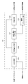
- FIG. 7 is a block diagram for explaining a detailed configuration example of the sound source extraction unit 12.
- the sound source extraction unit 12 has, for example, an AD (Analog to Digital) conversion unit 12A, a feature amount generation unit 12B, an extraction model unit 12C, and a reconstruction unit 12D.
- AD Analog to Digital
- the sound source extraction unit 12 There are two types of input for the sound source extraction unit 12. One is the microphone observation signal acquired by the air conduction microphone 2, and the other is the teaching information acquired by the auxiliary sensor 3.
- the microphone observation signal is converted into a digital signal by the AD conversion unit 12A and then sent to the feature amount generation unit 12B.
- the teaching information is sent to the feature amount generation unit 12B.
- the signal acquired by the auxiliary sensor 3 is an analog signal
- the analog signal is converted into a digital signal by an AD conversion unit different from the AD conversion unit 12A
- It is input to the feature amount generation unit 12B. What is converted into a digital signal in this way is also one of the teaching information generated based on the one-dimensional time series signal acquired by the auxiliary sensor 3.
- the feature amount generation unit 12B receives both the microphone observation signal and the teaching information as inputs, and generates a feature amount to be input to the extraction model unit 12C. It also retains the information necessary to convert the output of the extraction model unit 12C into a waveform.
- the model of the extraction model unit 12C the correspondence relationship to the clean target sound is learned in advance from the set of the microphone observation signal which is a mixed signal of the target sound and the disturbing sound and the teaching information which is a hint of the target sound to be extracted. It is a model that is.
- the input to the extraction model unit 12C will be referred to as an input feature amount
- the output from the extraction model unit 12C will be referred to as an output feature amount as appropriate.
- the reconstruction unit 12D converts the output feature amount from the extraction model unit 12C into a sound wave type or similar signal. At that time, information necessary for waveform generation is received from the feature amount generation unit 12B.
- the feature amount generation unit 12B includes a short-time Fourier transform unit 121B, a teaching information conversion unit 122B, a feature amount buffer unit 123B, and a feature amount alignment unit 124B.
- the microphone observation signal converted into a digital signal by the AD conversion unit 12A is input to the short-time Fourier transform unit 121B. Then, the microphone observation signal is converted into a signal in the time frequency domain, that is, a spectrum by the short-time Fourier transform unit 121B.
- the teaching information is a sound signal
- a short-time Fourier transform is performed in the same manner as the microphone observation signal.
- the teaching information is modal other than sound, it is possible to perform a short-time Fourier transform or use it without conversion.
- the signal converted by the short-time Fourier transform unit 121B and the teaching information conversion unit 122B is stored in the feature amount buffer unit 123B for a predetermined time.
- the time information and the conversion result are saved in a state of being associated with each other, and the feature amount can be output when there is a request from the latter module to acquire the past feature amount.
- the conversion result of the microphone observation signal is saved as a set of complex spectra because the information is used in the waveform generation in the subsequent stage.
- the output of the feature amount buffer unit 123B is used at two locations, specifically, the reconstruction unit 12D and the feature amount alignment unit 124B, respectively.
- the feature amount alignment unit 124B performs a process of matching the grain sizes of the two.
- the feature quantity derived from the microphone observation signal is generated once every 1/100 second. ..
- the feature amount derived from the teaching information is generated once every 1/200 seconds, one set of the feature amount derived from the microphone observation signal and two sets of the feature amount derived from the teaching information are combined.
- the generated data is generated, and it is used as input data for one time to the extraction model unit 12C.
- the feature amount derived from the teaching information is generated once every 1/50 second, two sets of the feature amount derived from the microphone observation signal and one set of the feature amount derived from the teaching information are used. Generate combined data. Further, at this stage, conversion from the complex spectrum to the amplitude spectrum is also performed as necessary. The output thus generated is sent to the extraction model unit 12C.
- a fixed length is cut out from the waveform of the microphone observation signal (see FIG. 9A) obtained by the AD conversion unit 12A, and a window function such as a humming window or a humming window is applied to them.
- This cut out unit is called a frame.
- X (K, t) is obtained from X (1, t) as an observation signal in the time frequency domain (see FIG. 9B).
- t represents the frame number
- K represents the total number of frequency bins.
- a set of data for one frame from X (1, t) to X (K, t) is called a spectrum, and a data structure in which a plurality of spectra are arranged in the time direction is called a spectrogram (see FIG. 9C).
- the horizontal axis represents the frame number and the vertical axis represents the frequency bin number
- the three spectra (X (1, t-1) to X (K, t-1)) from FIG. 9A are X.
- (1, t) to X (K, t) and X (1, t + 1) to X (K, t + 1)) are generated respectively.
- the extraction model unit 12C receives the output of the feature amount generation unit 12B as an input.
- the output of the feature amount generation unit 12B includes two types of data. One is a feature quantity derived from a microphone observation signal, and the other is a feature quantity derived from teaching information.
- the feature amount derived from the microphone observation signal will be referred to as a first feature amount
- the feature amount derived from the teaching information will be referred to as a second feature amount as appropriate.
- the extraction model unit 12C has, for example, an input layer 121C, an input layer 122C, an intermediate layer 123C including the intermediate layers 1 to n, and an output layer 124C.
- the extraction model unit 12C shown in FIG. 10 represents a so-called neural network. The reason why the input layer is divided into the input layer 121C and the input layer 122C is that two types of feature quantities are input to each.
- the input layer 121C is an input layer to which the first feature amount is input
- the input layer 122C is an input layer to which the second feature amount is input.
- the type and structure (number of layers) of the neural network can be set arbitrarily, and the correspondence to a clean target sound is learned in advance from the set of the first feature amount and the second feature amount by the learning system described later. ing.
- the extraction model unit 12C inputs the first feature amount to the input layer 121C and the second feature amount to the input layer 122C, respectively, and performs a predetermined forward propagation process (forward propagation) to obtain clean output data. Generates an output feature amount corresponding to the target sound signal of the target sound.
- a predetermined forward propagation process forward propagation
- an amplitude spectrum corresponding to a clean target sound an amplitude spectrum corresponding to a clean target sound, a time frequency mask for generating a clean target sound spectrum from a microphone observation signal spectrum, or the like can be used.
- the two types of input data are merged in the intermediate layer immediately after (intermediate layer 1), but they may be merged in the intermediate layer closer to the output layer 124C.
- the number of layers from each input layer to the confluence may be different, and as an example, a network structure in which one of the input data is input from the intermediate layer may be used.
- There are multiple possible methods for merging two types of data in the intermediate layer as follows. One is a method of concatenate the vector format data output from the immediately preceding two layers. The other is a method of multiplying the elements if the number of elements of the two vectors is the same.
- the reconstruction unit 12D converts the output of the extraction model unit 12C into sound wave type or sound-like data. In order to perform such processing, necessary data is also received from the feature amount buffer unit 123B in the feature amount generation unit 12B.
- the reconstruction unit 12D has a complex spectrogram generation unit 121D and an inverse short-time Fourier transform unit 122D.
- the complex spectrogram generation unit 121D integrates the output of the extraction model unit 12C and the data from the feature amount generation unit 12B to generate a complex spectrogram of the target sound.
- the method of generation depends on whether the output of the extraction model unit is an amplitude spectrum or a time-frequency mask. In the case of the amplitude spectrum, the phase information is missing, so it is necessary to add (restore) the phase information in order to convert it into a waveform.
- a known technique can be applied for phase restoration. For example, a complex spectrum of a microphone observation signal at the same timing is acquired from the feature amount buffer unit 123B, and phase information is extracted from the complex spectrum and synthesized with the amplitude spectrum. Generates a complex spectrum of the target sound with.
- the time frequency mask after acquiring the complex spectrum of the microphone observation signal as well, the complex spectrum of the target sound is generated by applying the time frequency mask to the complex spectrum (multiplying each time frequency).
- a known method for example, the method described in Japanese Patent Application Laid-Open No. 2015-55543
- Japanese Patent Application Laid-Open No. 2015-55543 can be used.
- the inverse short-time Fourier transform unit 122D converts the complex spectrum into a waveform.
- the inverse short-time Fourier transform comprises an inverse Fourier transform, overlap addition, and the like.
- Known methods for example, the methods described in JP-A-2018-64215) can be applied to these methods.
- the reconstruction unit 12D may convert data other than the waveform, or to omit the reconstruction unit 12D itself.
- the reconstruction unit 12D outputs the output of the extraction model unit 12C to the amplitude spectrum. All you have to do is convert it to. Further, when the extraction model unit 12C outputs the amplitude spectrum itself, the reconstruction unit 12D itself may be omitted.
- the learning system of the extraction model unit 12C will be described with reference to FIGS. 12 and 13.
- Such a learning system is used to perform predetermined learning in advance for the extraction model unit 12C.
- the learning system described below is assumed to be a system different from the signal processing device 10 except for the extraction model unit 12C, but the configuration related to the learning system may be incorporated in the signal processing device 10. ..
- the basic operation of the learning system is, for example, as follows (1) to (3), and repeating the process from (1) to (3) is called learning.
- Input feature amount and teacher data (ideal output feature amount with respect to the input feature amount) are generated from the target sound data set 21 and the disturbing sound data set 22.
- the input feature amount is input to the extraction model unit 12C, and the output feature amount is generated by forward propagation.
- the output feature amount and the teacher data are compared, and the parameters in the extraction model are updated so that the error becomes small, in other words, the loss value in the loss function is minimized.
- the pair of input features and teacher data will be referred to as learning data as appropriate below.
- the training data generates four types as shown in FIG.
- (a) is data for learning to extract the target sound when the target sound and the disturbing sound are mixed, and (b) outputs the utterance in a quiet environment without deterioration.
- (C) is data for outputting silence when the user is not speaking, and (d) is data for outputting silence when the user is not speaking in a quiet environment. This is the data to be output.
- "none" means that the signal itself exists, but the component derived from the target sound is not included in the signal itself.
- the target sound data set 21 is a set composed of a pair of a target sound wave type and teaching information synchronized with the target sound wave type.
- a pair of auxiliary sensor input signals is also included in this dataset.
- the disturbing sound data set 22 is a set composed of sounds that can be disturbing sounds. Since the voice can also be a disturbing sound, the disturbing sound data set 22 includes both voice and non-voice. Further, in order to generate the learning data corresponding to (b) in FIG. 13 and the learning data corresponding to (d) in FIG. 13, the microphone observation signal observed in a quiet place is also included in this data set. At the time of learning, one of the pairs consisting of the target sound wave shape and the teaching information is randomly extracted from the target sound data set 21. The teaching information in it is input to the mixing unit 24 when it is acquired by the air conduction microphone, but is directly input to the feature amount generation unit 25 when it is acquired by a sensor other than the air conduction microphone. ..
- the target sound wave type is input to the mixing unit 23 and the teacher data generation unit 26, respectively.
- one or more sound wave shapes are randomly taken out from the disturbing sound data set 22, and the sound wave shapes are input to the mixing unit 23.
- the auxiliary sensor is other than the air conduction microphone, the waveform extracted from the disturbing sound data set 22 is also input to the mixing unit 24.
- the mixing unit 23 mixes the target sound wave type and one or more interfering sound wave types at a predetermined mixing ratio (SN ratio (Signal Noise Ratio)).
- the mixing result corresponds to the microphone observation signal and is sent to the feature amount generation unit 25.
- the mixing unit 24 is a module applied when the auxiliary sensor 3 is an air conduction microphone, and mixes disturbing sounds at a predetermined mixing ratio with respect to teaching information which is a sound signal. The reason for mixing the disturbing sound in the mixing unit 24 is to enable good sound source extraction even if the disturbing sound is mixed in the teaching information to some extent.
- the extraction model unit 12C is a neural network before and during learning, and its configuration is the same as that in FIG.
- the teacher data generation unit 26 generates teacher data which is an ideal output feature amount.
- the shape of the teacher data is basically the same as the output feature amount, such as an amplitude spectrum and a time-frequency mask. However, as will be described later, it is possible to combine the output feature amount of the extraction model unit 12C as a time-frequency mask and the teacher data as an amplitude spectrum.
- the teacher data differs depending on the presence or absence of the target sound and the disturbing sound.
- the output feature amount corresponds to the target sound
- the output feature amount corresponds to silence.
- the comparison unit 27 compares the output of the extraction model unit 12C with the teacher data, and calculates the update value for the parameter included in the extraction model unit 12C so that the loss value in the loss function is reduced.
- a mean square error or the like can be used as the loss function used in the comparison.
- a method of comparison and a method of updating parameters a method known as a learning algorithm of a neural network can be applied.
- FIG. 14 is a diagram showing a specific example of the air conduction microphone 2 and the auxiliary sensor 3 in the over-ear type headphones 30.
- the outside (opposite to the auricle side) microphone 32 and the inside (auricle side) microphone 33 are provided on the outside and inside of the ear cup 31, which is a component that covers the ear, respectively.
- the outer microphone 32 and the inner microphone 33 for example, a microphone provided for noise cancellation can be applied.
- the type of microphone both the outside and the inside are air conduction microphones, but the purpose of use is different.
- the outer microphone 32 corresponds to the air-conducting microphone 2 described above, and is used to acquire a sound in which a target sound and an interfering sound are mixed.
- the inner microphone 33 corresponds to the auxiliary sensor 3.
- the speech (target sound) of the headphone wearer is observed not only through the atmosphere with the outer microphone 32, but also with the inner microphone 33 via the inner ear and the ear canal.
- the disturbing sound is observed not only by the outer microphone 32 but also by the inner microphone 33, but since it is attenuated to some extent by the ear cup 31, the sound is observed in the inner microphone 33 in a state where the target sound is dominant over the disturbing sound.
- the target sound observed by the inner microphone 33 has a frequency distribution different from that derived from the outer microphone 32 because it passes through the inner ear, and sounds other than speech (swallowing sound, etc.) generated in the body are heard. Since the sound may be picked up, it is not always appropriate for another person to hear the sound observed by the inner microphone 33 or to input the sound as it is into voice recognition.
- the problem is solved by using the sound signal observed by the inner microphone 33 as teaching information for sound source extraction.
- the problem is solved by the following reasons (1) to (3).
- the extraction result is generated from the observation signal of the outer microphone 32 which is the air conduction microphone 2, and since the teacher data derived from the air conduction microphone is used during learning, the frequency distribution of the target sound in the extraction result is a quiet environment. It is close to the one recorded in.
- (2) Not only the target sound but also the disturbing sound may be mixed in the sound observed by the inner microphone 33, that is, the teaching information, but the target sound is output from the teaching information and the outer microphone observation signal at the time of learning.
- the extraction result is a relatively clean voice because the correspondence is learned using such data.
- Even if the swallowing sound or the like is observed by the inner microphone 33, the sound is not observed by the outer microphone 32, so that the sound does not appear in the extraction result.
- FIG. 15 is a diagram showing a specific example of the air conduction microphone 2 and the auxiliary sensor 3 in the one-ear insertion type earphone 40.
- An outer microphone 42 is provided on the outside of the housing 41.
- the outer microphone 42 corresponds to the air conduction microphone 2.
- the outer microphone 42 observes a mixed sound in which the target sound and the disturbing sound transmitted through the air are mixed.
- the earpiece 43 is a part inserted into the user's ear canal.
- An inner microphone 44 is provided on a part of the earpiece 43.
- the inner microphone 44 corresponds to the auxiliary sensor 3.
- a sound in which the target sound transmitted via the inner ear and the disturbing sound attenuated through the housing portion are mixed is observed. Since the method of extracting the sound source is the same as that of the headphones shown in FIG. 14, duplicate description will be omitted.
- the auxiliary sensor 3 is not limited to the air conduction microphone, and other types of microphones and sensors other than the microphone can also be used.
- a microphone capable of acquiring sound waves directly propagating in the body such as a bone conduction microphone or a pharyngeal microphone, may be used. Since the sound waves propagating in the body are not easily affected by the disturbing sound transmitted through the atmosphere, the sound signals acquired by these microphones are considered to be close to the user's clean spoken voice.
- problems such as a difference in frequency distribution and swallowing sound may occur.
- the problem is solved by using a bone conduction microphone, a pharyngeal microphone, or the like as the auxiliary sensor 3 and extracting a sound source with instruction.
- a sensor that detects a signal other than sound waves for example, an optical sensor.
- the surface of a sound-producing object for example, muscle
- the skin of the throat and cheeks near the vocal organs is vibrating in response to the sound produced by itself. Therefore, by detecting the vibration with an optical sensor by a non-contact method, it is possible to detect the presence or absence of the utterance itself or estimate the voice itself.
- a technique for detecting an utterance section using an optical sensor that detects vibration has been proposed.
- a technique has been proposed in which the brightness of spots generated by irradiating the skin with a laser is observed with a high frame rate camera, and the sound is estimated from the change in the brightness.
- the optical sensor is also used in this example, the detection result by the optical sensor is used not for detecting the utterance section or estimating the sound, but for extracting the sound source with instruction.
- optical sensor A specific example using an optical sensor will be described.
- a light source such as a laser pointer or LED is applied to the skin near the vocal organs such as the cheeks, throat, and back of the head.
- the exposure to light causes spots of light on the skin.
- the brightness of the spots is observed by an optical sensor.
- This optical sensor corresponds to the auxiliary sensor 3 and is attached to the user's body.
- the optical sensor and the light source may be integrated to facilitate light collection.
- the air conduction microphone 2 may be integrated with the optical sensor and the light source to facilitate carrying.
- the signal acquired by the air conduction microphone 2 is input to this module as a microphone observation signal, and the signal acquired by the optical sensor is input as teaching information.
- the optical sensor that detects vibration is used as the auxiliary sensor 3, but other types of sensors can also be used as long as the sensor acquires a signal synchronized with the user's utterance.
- sensors include an electromyographic sensor for acquiring the myoelectric potential of the muscle near the mandible and the lip, an acceleration sensor for acquiring the movement near the mandible, and the like.
- FIG. 16 is a flowchart showing the flow of the entire processing performed by the signal processing device 10 according to the embodiment.
- step ST2 the auxiliary sensor 3 acquires teaching information which is a one-dimensional time-series signal. Then, the process proceeds to step ST3.
- step ST3 the sound source extraction unit 12 generates an extraction result, that is, a target sound signal, using the microphone observation signal and the teaching information. Then, the process proceeds to step ST4.
- step ST4 it is determined whether or not a series of processes has been completed. Such determination processing is performed, for example, by the control unit 13 of the signal processing device 10. If the series of processes is not completed, the process returns to step ST1 and the above-described process is repeated.
- the post-processing unit 14 performs the process. As described above, the processing by the post-processing unit 14 is processing (calling, recording, voice recognition, etc.) according to the device to which the signal processing device 10 is applied.
- step ST11 the AD conversion process is performed by the AD conversion unit 12A. Specifically, the analog signal acquired by the air conduction microphone 2 is converted into a microphone observation signal which is a digital signal. When a microphone is applied as the auxiliary sensor 3, the analog signal acquired by the auxiliary sensor 3 is converted into teaching information which is a digital signal. Then, the process proceeds to step ST12.
- step ST12 the feature amount generation process is performed by the feature amount generation unit 12B. Specifically, the microphone observation signal and the teaching information are each converted into an input feature amount by the feature amount generation unit 12B. Then, the process proceeds to step ST13.
- step ST13 the output feature amount generation process is performed by the extraction model unit 12C. Specifically, the input feature amount generated in step ST12 is input to the neural network which is an extraction model, and the output feature amount is generated by performing a predetermined forward propagation process (forward propagation). Then, the process proceeds to step ST14.
- step ST14 the reconstruction process is performed by the reconstruction unit 12D. Specifically, by applying a complex spectrum generation, an inverse short-time Fourier transform, or the like to the output feature amount generated in step ST13, a sound wave type or a target sound signal which is similar data is generated. Then, the process ends.
- data other than the sound wave type may be generated or the reconstruction processing itself may be omitted.
- a feature amount for voice recognition may be generated in the reconstruction process, or an amplitude spectrum may be generated in the reconstruction process and the amplitude spectrum may be used for voice recognition in voice recognition.
- a feature quantity may be generated.
- the extraction model is trained to output the amplitude spectrum, the reconstruction process itself may be skipped.
- the signal processing device 10 of the embodiment is an auxiliary microphone 2 that acquires a mixed sound (microphone observation signal) in which a target sound and an interfering sound are mixed, and an auxiliary that acquires a one-dimensional time series synchronized with a user's speech. It is equipped with a sensor 3.
- a sensor 3 By extracting the sound source with instruction using the signal acquired by the auxiliary sensor 3 as the instruction information for the microphone observation signal, it is possible to selectively extract only the user's speech when the disturbing sound is voice.
- the disturbing sound is non-speech, highly accurate extraction becomes possible because the amount of information of the input data increases as compared with the case where there is no teaching information.
- the teaching information may include disturbing sounds as long as the data is similar to the data used at the time of learning. Further, the teaching information may be sound or other than sound. That is, since the restriction that the teaching information is sound is not required, any one-dimensional time-series signal synchronized with the utterance can be used as the teaching information. Further, according to the present embodiment, the minimum number of sensors is two, the air conduction microphone 2 and the auxiliary sensor 3. Therefore, the system itself can be miniaturized as compared with the case where sound source extraction is realized by beamforming processing using a large number of air conduction microphones.
- the embodiment can be applied to various situations. For example, it is conceivable to apply a signal that is not a one-dimensional time-series signal, for example, image information including spatial information as teaching information.
- image information including spatial information
- teaching information used in the embodiment is the user's utterance transmitted via the inner ear, the vibration of the speaker's skin, the movement of the muscle near the speaker's mouth, and the like, and a sensor for observing them. Is easy for the user to wear or carry. Therefore, the embodiment can be easily applied even in a situation where the user moves.
- the signal synchronized with the user's utterance is used as the teaching information, high-precision extraction can be performed even when the user's clean voice cannot be acquired. Therefore, it is possible to easily realize that one signal processing device 10 can be shared by a plurality of people or used by an unspecified number of people for a short time.
- Modification 1 is an example of simultaneously estimating the sound source extraction with instruction and the utterance interval estimation.
- the sound source extraction unit 12 generates the extraction result
- the utterance section estimation unit 14C generates the utterance section information based on the extraction result.
- the extraction result is generated.
- utterance section information is generated.
- the reason for performing such simultaneous estimation is to improve the accuracy of utterance section estimation when the disturbing sound is also voice. This point will be described with reference to FIG.
- the recognition accuracy may be significantly lower than when the disturbing sound is non-voice, and one of the causes is the failure of the speech interval estimation.
- the method of estimating the utterance section based on whether or not the input sound seems to be voice if both the target sound and the disturbing sound are voice, it is not possible to distinguish between the two. Leads to a recognition error.
- an extra word string derived from the interfering sound is connected before and after the word string derived from the original target sound.
- An object may be obtained as a recognition result, or an extra recognition result may be generated as a result of detecting that part as an utterance section when only a disturbing sound is sounding.
- the same problem may occur as long as the extraction result has an unerased residual sound. That is, the extraction result is not always an ideal signal from which the disturbing sound is completely removed (see FIG. 2D), and there is a case where a low volume sound derived from the disturbing sound is connected before and after the target sound.
- the utterance section is estimated for such a signal, a section longer than the true target sound may be estimated as the utterance section, or the unerased residual sound of the disturbing sound may be detected as the utterance section.
- the utterance section estimation unit 14C intends to improve the section estimation accuracy by using the teaching information derived from the auxiliary sensor 3 in addition to the extraction result output from the sound source extraction unit 12, but the disturbing sound is a voice.
- the teaching information for example, when the disturbing sound 4B is also a voice in FIG. 2B, there is still a possibility that a section longer than the original utterance is estimated as the utterance section.
- FIG. 18 is a diagram showing a configuration example of the signal processing device (signal processing device 10A) according to the first modification.
- the difference between the signal processing device 10A shown in FIG. 18 and the signal processing device 10 specifically shown in FIG. 6 is that the sound source extraction unit 12 and the utterance section estimation unit 14C related to the signal processing device 10 are integrated to produce a sound source. It has been replaced by a module called the extraction / utterance section estimation unit 52.
- the other is utterance section information, and this utterance section information is also sent to the voice recognition unit 14D.
- the details of the sound source extraction / utterance section estimation unit 52 are shown in FIG.
- the difference between the sound source extraction / speech section estimation unit 52 and the sound source extraction unit 12 is that the extraction model unit 12C has been replaced with the extraction / detection model unit 12F and the section tracking unit 12G has been newly provided.
- Module is the same as the module of the sound source extraction unit 12.
- the extraction / detection model unit 12F There are two outputs of the extraction / detection model unit 12F. One output is output to the reconstruction unit 12D, and a target sound signal which is a sound source extraction result is generated. The other output is sent to the section tracking unit 12G.
- the latter data is the discrimination result of utterance detection, for example, the discrimination result binarized for each frame. That is, the presence / absence of the user's utterance in that frame is expressed by a value of "1" or "0", respectively. Since it is the presence or absence of utterance and not the presence or absence of voice, the ideal value is "0" when a disturbing sound, which is voice, is generated at the timing when the user is not uttering.
- the section tracking unit 12G obtains the utterance start time and the utterance start time, which are the utterance section information, by tracking the discrimination result for each frame in the time direction.
- the determination result of 1 continues for a predetermined time or longer, it is regarded as the beginning of the utterance, and similarly, if the determination result of 0 continues for the predetermined time or longer, it is regarded as the end of the utterance.
- tracking may be performed by a known method based on learning using a neural network.
- the discrimination result output from the extraction / detection model unit 12F is binary, but instead, a continuous value may be output and the interval tracking unit 12G may perform binarization according to a predetermined threshold value. good.
- the sound source extraction result and the utterance section information obtained in this way are sent to the voice recognition unit 14D.
- the difference between the extraction / detection model unit 12F and the extraction model unit 12C is that there are two types of output layers (output layer 121F and output layer 122F).
- the output layer 121F operates in the same manner as the output layer 124C of the extraction model unit 12C to output data corresponding to the sound source extraction result.
- the output layer 122F outputs the determination result of the utterance detection. Specifically, it is a discrimination result binarized for each frame.
- the branch on the output side occurs in the intermediate layer n which is the previous layer, but the branch may be generated in the intermediate layer closer to the input layer than that.
- the number of layers from the intermediate layer in which branching occurs to each output layer may be different, and as an example, a network structure in which one of the output data is output from the intermediate layer may be used. I do not care.
- FIG. 21 shows a type of multitask learning machine.
- a known method can be applied to multitask learning.
- the target sound data set 61 is a set composed of the following three signal sets (a) to (c). It is (a) a target sound wave type (a sound wave type consisting of a voice utterance which is a target sound and silence of a predetermined length connected before and after it), (b) teaching information synchronized with (a), (c) ( It is an utterance discrimination flag synchronized with a).
- a target sound wave type a sound wave type consisting of a voice utterance which is a target sound and silence of a predetermined length connected before and after it
- teaching information synchronized with (a)
- (c) It is an utterance discrimination flag synchronized with a).
- (c) As an example of (c) above, if (a) is divided into predetermined time intervals (for example, the same time interval as the shift width of the short-time Fourier transform in FIG. 9), and if an utterance exists within each time interval, " A bit string generated by assigning a value of "1" or a value of "0" can be considered.
- one set is randomly taken out from the target sound data set 61, and the teaching information in the set is the mixing unit 64 (when the teaching information is acquired by the air conduction microphone) or the feature amount generation unit 65 (it).
- the target sound wave type is output to the mixing unit 63 and the teacher data generation unit 66, and the speech discrimination flag is output to the teacher data generation unit 67.
- one or more sound wave shapes are randomly extracted from the disturbing sound data set 62, and the extracted sound wave shapes are sent to the mixing unit 63.
- the teaching information is acquired by the air conduction microphone, the sound wave form of the disturbing sound is also sent to the mixing unit 64.
- the extraction / detection model unit 12F outputs two types of data, so prepare teacher data for each.
- the teacher data generation unit 66 generates teacher data corresponding to the sound source extraction result.
- the teacher data generation unit 67 generates teacher data corresponding to the utterance detection result.
- the utterance discrimination flag is a bit string as described above, it can be used as it is as teacher data.
- the teacher data generated by the teacher data generation unit 66 will be referred to as teacher data 1D
- the teacher data generated by the teacher data generation unit 67 will be referred to as teacher data 2D.
- the output corresponding to the sound source extraction result is output to the comparison unit 70, and is compared with the teacher data 1D by the comparison unit 70.
- the operation of the comparison unit 70 is the same as that of the comparison unit 27 in FIG. 12 described above.
- the output corresponding to the utterance detection result is output to the comparison unit 71, and is compared with the teacher data 2D by the comparison unit 71.
- the comparison unit 71 also uses the loss function in the same manner as the comparison unit 70, but this is a loss function for learning a binary classifier.
- the parameter update value calculation unit 72 calculates the update value for the parameter of the extraction / detection model unit 12F so that the loss value decreases from each loss value calculated by the two comparison units 70 and the comparison unit 71.
- a known method can be used for the parameter update method in multitask learning.
- Modification 2 In the above-described modification 1, the sound source extraction result and the utterance section information are individually sent to the voice recognition unit 14D side, and the voice recognition unit 14D side divides each utterance section and generates a word string which is the recognition result. I was supposed to do it. On the other hand, in the modification 2, the data in which the sound source extraction result and the utterance section information are integrated may be once generated, and the generated data may be output.
- the second modification will be described.
- FIG. 22 is a diagram showing a configuration example of the signal processing device (signal processing device 10B) according to the modification 2.
- the difference between the signal processing device 10B and the signal processing device 10A is that in the signal processing device 10B, two types of data (sound source extraction result and speech section information) output from the sound source extraction / speech section estimation unit 52 are silenced outside the section. It is a point that is input to the unit 55 and a point that the output of the out-of-section silencer unit 55 is input to the newly provided speech division unit 14H or the voice recognition unit 14D.
- Other configurations are the same as the configuration of the signal processing device 10A.
- the out-of-section silencer 55 generates a new sound signal by applying the utterance section information to the sound source extraction result which is a sound signal. Specifically, the out-of-section silencer 55 performs a process of replacing the portion of the sound signal corresponding to the time outside the utterance section with silence or near-silence.
- the near-silence sound is a signal obtained by multiplying the sound source extraction result by a positive constant close to 0. Further, when the sound is not reproduced, instead of replacing it with silence, it may be replaced with noise of a type that does not adversely affect the utterance dividing unit 14H and the voice recognition unit 14D in the subsequent stage.
- the output of the out-of-section silencer 55 is a continuous stream, and in order to input it to the voice recognition unit 14D, either method (1) or (2) below is used.
- An utterance dividing unit 14H is added between the out-of-section silence unit 55 and the voice recognition unit 14D.
- (2) Use voice recognition corresponding to stream input, which is called sequential voice recognition. In the case of (2), the utterance dividing unit 14H may not be provided.
- a known method for example, the method described in Japanese Patent No. 4182444 can be applied.
- a known method for sequential speech recognition, a known method (for example, the method described in JP2012-226608) can be applied.
- the out-of-section silencer 55 When the out-of-section silencer 55 operates, a sound signal of silence (or a sound that does not adversely affect the operation of the subsequent stage) is input except for the section in which the user is speaking, so that the input speech division
- the unit 14H or the voice recognition unit 14D can perform more accurate operations than when the sound source extraction result is directly input.
- the out-of-section silence section 55 after the sound source / utterance section estimation section 52 the utterance division section 14H and the voice recognition section 14D are integrated not only for a system equipped with a sequential voice recognizer.
- the teaching sound source extraction of the present disclosure can also be applied to the system.
- the utterance section estimation When the utterance section estimation is performed on the sound source extraction result, when the disturbing sound is also voice, the utterance section estimation reacts to the unerased remaining of the disturbing sound, leading to erroneous recognition or generating an extra recognition result. It may happen.
- the utterance section estimation by performing two estimation processes of sound source extraction and speech interval estimation at the same time, even if the sound source extraction result includes the unerased residual sound, accurate speech section estimation is performed independently of it. As a result, the speech recognition accuracy can be improved.
- All or part of the processing in the above-mentioned signal processing device may be performed by a server or the like on the cloud.
- the target sound may be a voice other than the voice emitted by a person (for example, the voice of a robot or a pet).
- the auxiliary sensor may be attached to a robot or pet other than a person.
- the auxiliary sensor may be a plurality of auxiliary sensors of different types, and the auxiliary sensor used may be switched according to the environment in which the signal processing device is used.
- the present disclosure can also be applied when generating a sound source for each object. Since the "mixing section 24" of FIG. 12 and the “mixing section 64" of FIG. 21 can be omitted depending on the type of the auxiliary sensor, the "mixing section 24" of FIG. 12 and the “mixing section 64" of FIG. 21 Each of is in parentheses.
- the present disclosure may also adopt the following configuration.
- a signal processing device including a sound source extraction unit that extracts a target sound signal corresponding to the target sound from the microphone signal based on the one-dimensional time-series signal.
- the sound source extraction unit extracts the target sound signal by using the teaching information generated based on the one-dimensional time series signal.
- the auxiliary sensor is a sensor mounted on the source of the target sound.
- the microphone signal is a signal detected by the first microphone.
- the signal processing device according to any one of (1) to (3), wherein the auxiliary sensor is a second microphone different from the first microphone.
- the signal processing device wherein the first microphone is a microphone provided outside the housing of the headphones, and the second microphone is a microphone provided inside the housing.
- the auxiliary sensor is a sensor that detects sound waves propagating in the body.
- the signal processing device is a sensor that detects a signal other than a sound wave.
- the auxiliary sensor is a sensor that detects muscle movement.
- the signal processing device which has a reproduction unit for reproducing the target sound signal extracted by the sound source extraction unit.
- the signal processing device which has a communication unit that transmits the target sound signal extracted by the sound source extraction unit to an external device.
- the utterance section estimation unit Based on the extraction result by the sound source extraction unit, the utterance section estimation unit that estimates the utterance section indicating the presence or absence of utterance and generates the utterance section information that is the result,
- the signal processing device according to any one of (1) to (8), which has a voice recognition unit that performs voice recognition in the utterance section.
- the sound source extraction unit is further configured as a sound source extraction / utterance section estimation unit that estimates an utterance section indicating the presence or absence of utterance and generates utterance section information as a result.
- the signal processing device according to any one of (1) to (8), wherein the sound source extraction / utterance section estimation unit outputs the target sound signal and the utterance section information.
- (13) Based on the speech section information output from the sound source extraction / speech section estimation unit, the sound signal corresponding to the time outside the speech section of the target sound signal is determined, and the determined sound signal is silenced.
- the sound source extraction unit receives a first feature amount based on the microphone signal and a second feature amount based on the one-dimensional time-series signal as inputs, and performs forward propagation processing on the inputs.
- the signal processing apparatus according to any one of (1) to (8), (11) or (12), which has an extraction model unit that outputs an output feature amount.
- the sound source extraction unit receives a first feature amount based on the microphone signal and a second feature amount based on the one-dimensional time series signal as inputs, and performs forward propagation processing on the inputs.
- the signal processing device according to any one of (1) to (8), (12) or (13), which has an extraction / detection model unit that outputs a plurality of output feature amounts.
- the signal processing device which has a reconstruction unit that generates at least the target sound signal based on the output feature amount.
- a microphone signal including a mixed sound in which a target sound and a sound other than the target sound are mixed and a one-dimensional time series signal synchronized with the target sound acquired by an auxiliary sensor are input to the input unit.
- a signal processing method in which a sound source extraction unit extracts a target sound signal corresponding to the target sound from the microphone signal based on the one-dimensional time-series signal.
Landscapes
- Engineering & Computer Science (AREA)
- Acoustics & Sound (AREA)
- Physics & Mathematics (AREA)
- Health & Medical Sciences (AREA)
- Signal Processing (AREA)
- Audiology, Speech & Language Pathology (AREA)
- Human Computer Interaction (AREA)
- Computational Linguistics (AREA)
- Multimedia (AREA)
- Quality & Reliability (AREA)
- General Health & Medical Sciences (AREA)
- Otolaryngology (AREA)
- Circuit For Audible Band Transducer (AREA)
Abstract
目的音と目的音以外の音とが混合された混合音を含むマイクロホン信号と、補助センサによって取得された、目的音と同期している1次元の時系列信号とが入力される入力部と、1次元の時系列信号に基づいて、マイクロホン信号から目的音に対応する目的音信号を抽出する音源抽出部とを有する信号処理装置である。
Description
本開示は、信号処理装置、信号処理方法及びプログラムに関する。
ユーザが発話した音声とそれ以外の音声(例えば、周囲の騒音)とが混じった混合音から、ユーザが発話した音声を抽出する技術が開発されている(例えば、非特許文献1及び非特許文献2の参照のこと)。
A. Ephrat、 I. Mosseri、 O. Lang、 T. Dekel、 K. Wilson、 A. Hassidim、 W. Freeman、 M. Rubinstein、"Looking to Listen at the Cocktail Party: A Speaker-Independent Audio-Visual Model for Speech Separation"、[online]、2018年8月9日、[2019年4月5日検索]、インターネット<URL:https://arxiv.org/abs/1804.03619>
M. Delcroix, K. Zmolikova, K. Kinoshita, A. Ogawa, T. Nakatani, "Single Channel Target Speaker Extraction and Recognition with Speaker Beam", 2018 IEEE International Conference on Acoustics, Speech and Signal Processing (ICASSP), p.5554-5558, 2018
この分野では、抽出対象である音(以下、目的音と適宜、称する)を、目的音及び目的音以外の音が混合された混合音から適切に抽出できることが望まれている。
本開示は、上述した点に鑑みてなされたものであり、目的音及び目的音以外の音が混合された混合音から目的音を適切に抽出することができる信号処理装置、信号処理方法及びプログラムに関する。
本開示は、例えば、
目的音と目的音以外の音とが混合された混合音を含むマイクロホン信号と、補助センサによって取得された、目的音と同期している1次元の時系列信号とが入力される入力部と、
1次元の時系列信号に基づいて、マイクロホン信号から目的音に対応する目的音信号を抽出する音源抽出部と
を有する信号処理装置である。
目的音と目的音以外の音とが混合された混合音を含むマイクロホン信号と、補助センサによって取得された、目的音と同期している1次元の時系列信号とが入力される入力部と、
1次元の時系列信号に基づいて、マイクロホン信号から目的音に対応する目的音信号を抽出する音源抽出部と
を有する信号処理装置である。
また、本開示は、例えば、
目的音と目的音以外の音とが混合された混合音を含むマイクロホン信号と、補助センサによって取得された、目的音と同期している1次元の時系列信号とが入力部に入力され、
1次元の時系列信号に基づいて、マイクロホン信号から目的音に対応する目的音信号が音源抽出部により抽出される
信号処理方法である。
目的音と目的音以外の音とが混合された混合音を含むマイクロホン信号と、補助センサによって取得された、目的音と同期している1次元の時系列信号とが入力部に入力され、
1次元の時系列信号に基づいて、マイクロホン信号から目的音に対応する目的音信号が音源抽出部により抽出される
信号処理方法である。
また、本開示は、例えば、
目的音と目的音以外の音とが混合された混合音を含むマイクロホン信号と、補助センサによって取得された、目的音と同期している1次元の時系列信号とが入力部に入力され、
1次元の時系列信号に基づいて、マイクロホン信号から目的音に対応する目的音信号が音源抽出部により抽出される
信号処理方法をコンピュータに実行させるプログラムである。
目的音と目的音以外の音とが混合された混合音を含むマイクロホン信号と、補助センサによって取得された、目的音と同期している1次元の時系列信号とが入力部に入力され、
1次元の時系列信号に基づいて、マイクロホン信号から目的音に対応する目的音信号が音源抽出部により抽出される
信号処理方法をコンピュータに実行させるプログラムである。
以下、本開示の実施の形態等について図面を参照しながら説明する。なお、説明は以下の順序で行う。
<1.実施の形態>
<2.変形例>
以下に説明する実施の形態等は本開示の好適な具体例であり、本開示の内容がこれらの実施の形態等に限定されるものではない。
<1.実施の形態>
<2.変形例>
以下に説明する実施の形態等は本開示の好適な具体例であり、本開示の内容がこれらの実施の形態等に限定されるものではない。
<1.実施の形態>
[本開示の概要]
始めに、本開示の概要について説明する。本開示は、教示つき音源抽出の一種であり、混合音を取得するためのマイクロホン(気導マイクロホン)に加え、教示情報を取得するためのセンサ(補助センサ)を備える。補助センサの例として、以下のどれかあるいは2つ以上の組み合わせが考えられる。(1)外耳道など、妨害音よりも目的音の方が優勢な状態で取得できる位置に設置(装着)されたもう一つの気導マイクロホン、(2)骨伝導マイクロホンや咽頭マイクロホンなど、大気中以外を伝播する音波を取得するマイクロホン、(3)音以外のモーダルであって、ユーザの発話と同期している信号を取得するセンサ。補助センサは、例えば、目的音の発生源に装着される。上記(3)の例においてはユーザの発話と同期した信号として、頬や喉付近の皮膚の振動や、顔付近の筋肉の動きなどが考えられる。それらを取得する補助センサの具体例については後述する。
[本開示の概要]
始めに、本開示の概要について説明する。本開示は、教示つき音源抽出の一種であり、混合音を取得するためのマイクロホン(気導マイクロホン)に加え、教示情報を取得するためのセンサ(補助センサ)を備える。補助センサの例として、以下のどれかあるいは2つ以上の組み合わせが考えられる。(1)外耳道など、妨害音よりも目的音の方が優勢な状態で取得できる位置に設置(装着)されたもう一つの気導マイクロホン、(2)骨伝導マイクロホンや咽頭マイクロホンなど、大気中以外を伝播する音波を取得するマイクロホン、(3)音以外のモーダルであって、ユーザの発話と同期している信号を取得するセンサ。補助センサは、例えば、目的音の発生源に装着される。上記(3)の例においてはユーザの発話と同期した信号として、頬や喉付近の皮膚の振動や、顔付近の筋肉の動きなどが考えられる。それらを取得する補助センサの具体例については後述する。
図1は、本開示の実施の形態にかかる信号処理システム(信号処理システム1)を示している。信号処理システム1は、信号処理装置10を有している。信号処理装置10は、概略的には、入力部11及び音源抽出部12を有している。また、信号処理システム1は、音を収音する気導マイクロホン2及び補助センサ3を有している。気導マイクロホン2及び補助センサ3は、信号処理装置10の入力部11に対して接続されている。気導マイクロホン2及び補助センサ3は、入力部11に対して有線又は無線により接続されている。補助センサ3は、例えば、目的音の発生源に装着されるセンサである。本例における補助センサ3は、ユーザUAの近傍に配置されており、具体的には、ユーザUAの身体に装着されている。補助センサ3は、後述する目的音と同期した1次元の時系列信号を取得する。かかる時系列信号に基づいて教示情報が得られる。
信号処理システム1において音源抽出部12による抽出対象となる目的音とは、ユーザUAが発声した音声である。目的音は、必ず音声であり、且つ、指向性音源である。妨害音音源は、目的音以外の妨害音を発する音源である。これは音声の場合も非音声の場合もあり得、さらに同一の音源から両方の信号が発生する場合もあり得る。妨害音音源は指向性音源または無指向性音源である。妨害音音源の個数は0または1個以上の整数である。図1に示す例では、妨害音の一例として、ユーザUBが発声した音声が示されている。勿論、騒音(例えば、ドアの開閉の際の音や、上空を旋回するヘリコプターの音や、多くの人が存在する場所の雑踏の音など)も妨害音になり得る。気導マイクロホン2は、大気中を伝わる音を収録するマイクロホンであり、目的音と妨害音との混合音を取得する。以下の説明では、取得された混合音のことをマイクロホン観測信号と適宜、称する。
次に、図2A~図2Dを参照して、信号処理装置10で行われる処理の概略について説明する。図2A~図2Dでは、横軸が時間、縦軸が音量(またはパワー)をそれぞれ表わしている。
図2Aは、マイクロホン観測信号のイメージ図である。マイクロホン観測信号は、目的音に由来する成分4Aと妨害音に由来する成分4Bとが混合した信号である。
図2Bは、教示情報のイメージ図である。本例では、補助センサ3が気導マイクロホン2とは異なる位置に設置されたもう一つの気導マイクロホンである場合を想定している。従って、補助センサ3によって取得される1次元の時系列信号は、音信号である。かかる音信号が教示情報として使用される。図2Bは、目的音と妨害音とが混合しているという点は図1と同様だが、補助センサ3の装着位置がユーザの身体に装着されているため、妨害音に由来する成分4Bよりも目的音に由来する成分4Aの方が優勢な状態で観測される。
図2Cは、教示情報の他のイメージ図である。本例では、補助センサ3が気導マイクロホン以外のセンサである場合を想定している。気導マイクロホン以外のセンサで取得される信号の例として、骨伝導マイクロホンや咽頭マイクロホンなどによって取得される、ユーザの体内を伝播した音波や、マイクロホン以外のセンサで取得される、ユーザの頬や喉などの皮膚表面の振動や、口付近の筋肉の筋電位および加速度などがある。これらの信号は大気中を伝播しないため、妨害音の影響を受けにくいと考えられる。そのため、教示情報は主に目的音に由来する成分4Aで構成される。すなわち、ユーザの発話開始と共に信号強度が立ち上がり、発話終了と共に立ち下がる。
教示情報は目的音の発話と同期して取得されるため、目的音に由来する成分4Aと目的音に由来する成分4Bとの立ち上がり・立ち下がりのタイミングは、目的音に由来する成分4Aと同じである。
図1に示すように、信号処理装置10の音源抽出部12は、気導マイクロホン2由来のマイクロホン観測信号と補助センサ3由来の教示情報とを入力し、マイクロホン観測信号から妨害音由来の成分を消して目的音由来の成分を残すことで、抽出結果を生成する。
図2Dは、抽出結果のイメージである。理想的な抽出結果は、目的音に由来する成分4Aのみから構成される。このような抽出結果を生成するため、音源抽出部12はマイクロホン観測信号と教示情報とから抽出結果への対応付けを表わすモデルを有している。かかるモデルは大量のデータによって事前に学習されている。
[信号処理装置の構成例]
(全体の構成例)
図3は、実施の形態にかかる信号処理装置10の構成例を説明するための図である。上述したように、気導マイクロホン2は、大気中を伝わってくる目的音と目的音以外の音(妨害音)とが混合された混合音を観測する。補助センサ3はユーザの身体に装着されていて、目的音と同期した1次元の時系列信号を教示情報として取得する。気導マイクロホン2に収音されたマイクロホン観測信号及び補助センサ3により取得された1次元の時系列信号が信号処理装置10の入力部11を介して音源抽出部12に入力される。また、信号処理装置10は、信号処理装置10を統括的に制御する制御部13を有している。音源抽出部12は、気導マイクロホン2により収音される混合音から目的音に対応する目的音信号を抽出し、出力する。具体的には、音源抽出部12は、1次元の時系列信号に基づいて生成される教示情報を使用して目的音信号を抽出する。目的音信号は、後処理部14に出力される。
(全体の構成例)
図3は、実施の形態にかかる信号処理装置10の構成例を説明するための図である。上述したように、気導マイクロホン2は、大気中を伝わってくる目的音と目的音以外の音(妨害音)とが混合された混合音を観測する。補助センサ3はユーザの身体に装着されていて、目的音と同期した1次元の時系列信号を教示情報として取得する。気導マイクロホン2に収音されたマイクロホン観測信号及び補助センサ3により取得された1次元の時系列信号が信号処理装置10の入力部11を介して音源抽出部12に入力される。また、信号処理装置10は、信号処理装置10を統括的に制御する制御部13を有している。音源抽出部12は、気導マイクロホン2により収音される混合音から目的音に対応する目的音信号を抽出し、出力する。具体的には、音源抽出部12は、1次元の時系列信号に基づいて生成される教示情報を使用して目的音信号を抽出する。目的音信号は、後処理部14に出力される。
後処理部14の構成は、信号処理装置10が適用される機器に応じて異なる。図4は、後処理部14が、音再生部14Aにより構成される例を示している。音再生部14Aは、音信号を再生するための構成(アンプやスピーカ等)を有している。図示された例の場合には、目的音信号が音再生部14Aにより再生される。
図5は、後処理部14が、通信部14Bにより構成される例を示している。通信部14Bは、インターネットや所定の通信網等のネットワークを介して、目的音信号を外部機器に送信するための構成を有している。図示された例の場合には、目的音信号が通信部14Bにより送信される。また、外部機器から送信された音声信号が通信部14Bにより受信される。本例の場合は、信号処理装置10は、例えば、通信機器に適用される。
図6は、後処理部14が、発話区間推定部14C、音声認識部14D及びアプリケーション処理部14Eにより構成される例を示している。発話区間推定部14Cによって、気導マイクロホン2から音源抽出部12までは途切れのないストリームとして扱われていた信号が、発話という単位に分割される。発話区間推定(あるいは音声区間検出)の方法としては、公知の方法を適用することができる。さらに、発話区間推定部14Cの入力として、音源抽出部12の出力であるクリーンな目的音に加え、補助センサ3で取得された信号を使用しても良い(この場合における補助センサ3で取得された信号の流れが、図6では点線により示されている。)。即ち、音信号だけでなく、補助センサ3で取得された信号も併せて使用することで発話区間推定(検出)が行われても良い。かかる方法としても公知の方法を適用することができる。
発話区間推定部14Cは、分割された音そのものを出力するという形態も可能だが、音の代わりに開始時刻や終了時刻といった区間を示す発話区間情報を出力し、分割自体は発話区間情報を用いて音声認識部14Dで行うという形態も可能である。図6は、後者の形態を想定した例である。音声認識部14Dは、音源抽出部12の出力であるクリーンな目的音と発話区間推定部14Cの出力である区間情報とを入力とし、その区間に対応した単語列を音声認識結果として出力する。アプリケーション処理部14Eは、音声認識結果を利用する処理を担当するモジュールである。アプリケーション処理部14Eは、信号処理装置10が音声対話システムに適用される例であれば、応答生成や音声合成等を行うモジュールに対応する。また、信号処理装置10が音声翻訳システムに適用される例であれば、アプリケーション処理部14Eは、機械翻訳や音声合成等を行うモジュールに対応する。
(音源抽出部について)
図7は、音源抽出部12の詳細な構成例を説明するためのブロック図である。音源抽出部12は、例えば、AD(Analog to Digital)変換部12Aと、特徴量生成部12Bと、抽出モデル部12Cと、再構成部12Dとを有している。
図7は、音源抽出部12の詳細な構成例を説明するためのブロック図である。音源抽出部12は、例えば、AD(Analog to Digital)変換部12Aと、特徴量生成部12Bと、抽出モデル部12Cと、再構成部12Dとを有している。
音源抽出部12の入力は2種類ある。一方は気導マイクロホン2によって取得されたマイクロホン観測信号であり、他方は補助センサ3によって取得された教示情報である。マイクロホン観測信号は、AD変換部12Aによってデジタル信号に変換された後、特徴量生成部12Bに送られる。教示情報は特徴量生成部12Bに送られる。図7では省略されているが、補助センサ3で取得された信号がアナログ信号である場合は、当該アナログ信号が、AD変換部12Aとは別のAD変換部によりデジタル信号に変換された後に、特徴量生成部12Bに入力される。このようにデジタル信号に変換されたものも、補助センサ3で取得された1次元の時系列信号に基づいて生成される教示情報の一つである。
特徴量生成部12Bは、マイクロホン観測信号及び教示情報の両方を入力とし、抽出モデル部12Cに入力するための特徴量を生成する。また、抽出モデル部12Cの出力を波形に変換するために必要な情報の保持も行う。抽出モデル部12Cのモデルは、目的音と妨害音との混合信号であるマイクロホン観測信号と抽出すべき目的音のヒントとなる教示情報とのセットからクリーンな目的音への対応関係が予め学習されているモデルである。以降では、抽出モデル部12Cへの入力を入力特徴量、抽出モデル部12Cからの出力を出力特徴量と適宜、称する。
再構成部12Dは、抽出モデル部12Cからの出力特徴量を音波形またはそれに類する信号に変換する。その際に、特徴量生成部12Bから波形生成のために必要な情報を受け取る。
(音源抽出部が有する各構成の詳細について)
「特徴量生成部の詳細について」
次に、特徴量生成部12Bの詳細について図8を参照して説明する。図8では、特徴量としてスペクトルまたはそれに類するものを想定しているが、それ以外の特徴量も使用可能である。特徴量生成部12Bは、短時間フーリエ変換部121Bと、教示情報変換部122Bと、特徴量バッファー部123Bと、特徴量アライメント部124Bとを有している。
「特徴量生成部の詳細について」
次に、特徴量生成部12Bの詳細について図8を参照して説明する。図8では、特徴量としてスペクトルまたはそれに類するものを想定しているが、それ以外の特徴量も使用可能である。特徴量生成部12Bは、短時間フーリエ変換部121Bと、教示情報変換部122Bと、特徴量バッファー部123Bと、特徴量アライメント部124Bとを有している。
特徴量生成部12Bの入力としては、2種類の信号が存在する。一方の入力である、AD変換部12Aによりデジタル信号に変換されたマイクロホン観測信号が短時間フーリエ変換部121Bに入力される。そして、マイクロホン観測信号が、短時間フーリエ変換部121Bによって時間周波数領域の信号、即ち、スペクトルに変換される。
他方の入力である補助センサ3からの教示情報に対しては、教示情報変換部122Bによって信号の種類に応じた変換が行われる。教示情報が音信号である場合は、マイクロホン観測信号と同様に短時間フーリエ変換が行われる。教示情報が音以外のモーダルである場合は、短時間フーリエ変換を行うことも無変換のまま使用することも可能である。
短時間フーリエ変換部121B及び教示情報変換部122Bによって変換された信号は、所定の時間分だけ特徴量バッファー部123Bで保存される。ここでは、時間情報と変換結果とが対応付けられた状態で保存されており、後段のモジュールから過去の特徴量の取得というリクエストがあった場合にその特徴量を出力することができる。また、マイクロホン観測信号の変換結果については、その情報が後段での波形生成で使用されるため、複素スペクトルの集合として保存される。
特徴量バッファー部123Bの出力は、2箇所、具体的には再構成部12D及び特徴量アライメント部124Bのそれぞれで使用される。特徴量アライメント部124Bは、マイクロホン観測信号由来の特徴量と教示情報由来の特徴量とで時間の粒度が異なる場合に、両者の粒度を合わせる処理を行う。
例えば、マイクロホン観測信号のサンプリング周波数が16kHzであり、短時間フーリエ変換部121Bでのシフト幅が160サンプルとすると、マイクロホン観測信号由来の特徴量は1/100秒に1回の頻度で生成される。一方、教示情報由来の特徴量が1/200秒に1回の頻度で生成される場合は、マイクロホン観測信号由来の特徴量の1セット分と教示情報由来の特徴量の2セット分とを結合したデータを生成し、それを抽出モデル部12Cへの1回分の入力データとする。
逆に、教示情報由来の特徴量が1/50秒に1回の頻度で生成される場合は、マイクロホン観測信号由来の特徴量の2セット分と教示情報由来の特徴量の1セット分とを結合したデータを生成する。更に、この段階において、複素スペクトルから振幅スペクトルへの変換等も必要に応じて行う。こうして生成された出力が抽出モデル部12Cに送られる。
ここで、図9を参照して、上述した短時間フーリエ変換部121Bで行われる処理について説明する。AD変換部12Aによって得られたマイクロホン観測信号の波形(図9A参照)から一定長を切り出し、それらにハニング窓やハミング窓等の窓関数を適用する。この切り出した単位をフレームと呼ぶ。1フレーム分のデータに短時間フーリエ変換を適用することにより、時間周波数領域の観測信号として、例えば、X(1,t)からX(K,t)を得る(図9B参照)。ただし、tはフレーム番号、Kは周波数ビンの総数を表わす。切り出すフレームの間には重複があってもよく、そうすることで連続するフレーム間で時間周波数領域の信号の変化が滑らかになる。1フレーム分のデータであるX(1,t)からX(K,t)までのセットをスペクトルと呼び、複数のスペクトルを時間方向に並べたデータ構造をスペクトログラム(図9C参照)と呼ぶ。図9Cのスペクトログラムでは、横軸がフレーム番号を、縦軸が周波数ビン番号を表わし、図9Aから3本のスペクトル(X(1,t-1)からX(K,t-1)まで、X(1,t)からX(K,t)まで、X(1,t+1)からX(K,t+1)まで)がそれぞれ生成されている。
「抽出モデル部の詳細について」
次に、図10を参照して、抽出モデル部12Cの詳細について説明する。抽出モデル部12Cは特徴量生成部12Bの出力を入力とする。特徴量生成部12Bの出力には2種類のデータが含まれる。一方はマイクロホン観測信号由来の特徴量であり、他方は教示情報由来の特徴量である。以降では、マイクロホン観測信号由来の特徴量を第1特徴量、教示情報由来の特徴量を第2特徴量と適宜、称する。
次に、図10を参照して、抽出モデル部12Cの詳細について説明する。抽出モデル部12Cは特徴量生成部12Bの出力を入力とする。特徴量生成部12Bの出力には2種類のデータが含まれる。一方はマイクロホン観測信号由来の特徴量であり、他方は教示情報由来の特徴量である。以降では、マイクロホン観測信号由来の特徴量を第1特徴量、教示情報由来の特徴量を第2特徴量と適宜、称する。
抽出モデル部12Cは、例えば、入力層121Cと、入力層122Cと、中間層1~中間層nを含む中間層123Cと、出力層124Cとを有している。図10に示される抽出モデル部12Cは、所謂ニューラルネットワークを表わしている。入力層が入力層121C及び入力層122Cの2つに分かれている理由は、2種類の特徴量をそれぞれに入力するためである。
図10に示した例において、入力層121Cは第1特徴量が入力される入力層であり、入力層122Cは第2特徴量が入力される入力層である。ニューラルネットワークの種類や構造(層の数)は任意に設定可能であり、後述する学習系により、第1特徴量と第2特徴量とのセットからクリーンな目的音への対応関係が予め学習されている。
抽出モデル部12Cは、第1特徴量を入力層121Cに、第2特徴量を入力層122Cにそれぞれ入力し、所定の順方向伝播処理(forward propagation)を行うことで、出力データであるクリーンな目的音の目的音信号に相当する出力特徴量を生成する。出力特徴量の種類として、クリーンな目的音に対応した振幅スペクトルや、マイクロホン観測信号のスペクトルからクリーンな目的音のスペクトルを生成するための時間周波数マスクなどが使用可能である。
なお、図10では、2種類の入力データは直後の中間層である(中間層1)で合流されているが、それよりも出力層124Cに近い側の中間層で合流させても良い。その場合、各入力層から合流地点までの層の個数はそれぞれ異なっていても良く、一つの例として、入力データの一方が中間層から入力されるようなネットワーク構造を用いても構わない。2種類のデータを中間層で合流させる方法は、以下のように複数通りが考えられる。一つは、直前の2つの層から出力されるベクトル形式のデータを連結(concatenate)する方法である。もう一つは、2つのベクトルの要素数が同じであれば、要素同士を乗じるという方法である。
「再構成部の詳細について」
次に、図11を参照して、再構成部12Dの詳細について説明する。再構成部12Dは、抽出モデル部12Cの出力を音波形または音に類するデータに変換する。かかる処理を行うため、特徴量生成部12Bの中の特徴量バッファー部123Bからも必要なデータを受け取る。
次に、図11を参照して、再構成部12Dの詳細について説明する。再構成部12Dは、抽出モデル部12Cの出力を音波形または音に類するデータに変換する。かかる処理を行うため、特徴量生成部12Bの中の特徴量バッファー部123Bからも必要なデータを受け取る。
再構成部12Dは、複素スペクトログラム生成部121Dと、逆短時間フーリエ変換部122Dとを有している。複素スペクトログラム生成部121Dは、抽出モデル部12Cの出力及び特徴量生成部12Bからのデータを統合して目的音の複素スペクトログラムを生成する。生成の仕方は、抽出モデル部の出力が振幅スペクトルか時間周波数マスクかによって変わる。振幅スペクトルの場合は、位相情報が欠落しているため、波形に変換するためには位相情報を追加する(復元する)必要がある。位相の復元のためには公知の技術が適用可能であり、例えば、特徴量バッファー部123Bから同じタイミングのマイクロホン観測信号の複素スペクトルを取得し、そこから位相情報を取り出して振幅スペクトルと合成することで目的音の複素スペクトルを生成する。
一方、時間周波数マスクの場合は、同じくマイクロホン観測信号の複素スペクトルを取得した後、複素スペクトルに時間周波数マスクを適用する(時間周波数ごとに乗算する)ことで目的音の複素スペクトルを生成する。時間周波数マスクの適用については、公知の方法(例えば、特開2015-55843号公報に記載の方法)を使用することができる。
逆短時間フーリエ変換部122Dは、複素スペクトルを波形に変換する。逆短時間フーリエ変換は、逆フーリエ変換およびオーバーラップ加算等からなる。これらの方法については公知の方法(例えば、特開2018-64215号公報に記載の方法)を適用することができる。
なお、後段のモジュールによっては、再構成部12Dにおいて波形以外のデータに変換したり、或いは、再構成部12D自体を省略したりすることも可能である。例えば、後段のモジュールが発話区間検出および音声認識であり、そこで使用される特徴量が振幅スペクトルあるいはそこから生成可能なデータである場合、再構成部12Dは、抽出モデル部12Cの出力を振幅スペクトルに変換するだけで良い。さらに、抽出モデル部12Cが振幅スペクトルそのものを出力する場合は、再構成部12D自体を省略しても良い。
(抽出モデル部の学習系について)
次に、図12及び図13を参照して、抽出モデル部12Cの学習系について説明する。かかる学習系は抽出モデル部12Cに対して所定の学習を事前に行うために使用される。以下に説明する学習系は、抽出モデル部12Cを除き、信号処理装置10とは別システムであることを想定しているが、学習系にかかる構成が信号処理装置10に組み込まれていても良い。
次に、図12及び図13を参照して、抽出モデル部12Cの学習系について説明する。かかる学習系は抽出モデル部12Cに対して所定の学習を事前に行うために使用される。以下に説明する学習系は、抽出モデル部12Cを除き、信号処理装置10とは別システムであることを想定しているが、学習系にかかる構成が信号処理装置10に組み込まれていても良い。
学習系の基本的な動作は、例えば、以下の(1)から(3)の通りであり、(1)から(3)までのプロセスを繰り返し行うことを学習と呼ぶ。(1)目的音データセット21及び妨害音データセット22とから、入力特徴量及び教師データ(その入力特徴量に対する理想的な出力特徴量)が生成される。(2)入力特徴量が抽出モデル部12Cに入力され、順方向伝播によって出力特徴量が生成される。(3)出力特徴量と教師データとが比較され、誤差が小さくなるよう、換言すれば、損失関数における損失値を最小とするように抽出モデル内のパラメータが更新される。
入力特徴量と教師データとのペアを、以下では学習データと適宜、称する。学習データは図13に示すような4通りを生成する。この図において、(a)は目的音と妨害音とが混合している場合に目的音を抽出することを学習するためのデータであり、(b)は静かな環境での発話を劣化なく出力させるためのデータであり、(c)はユーザが発話をしていない場合に無音を出力させるためのデータであり、(d)は静かな環境においてユーザが何も発話していない場合に無音を出力させるためのデータである。なお、図13の教示情報において「無し」とは、信号自体は存在するものの、その中には目的音に由来する成分が含まれていないことを意味する。
これら4通りの学習データは、場合分けによってそれぞれを所定の割合で生成する。あるいは後述のように、静かな環境で収録された無音に近い音を目的音および妨害音のデータセットに含めておくことで、場合分けなしに全組み合わせが生成されるようにしても良い。
以下、学習系を構成するモジュールとその動作について説明する。目的音データセット21は、目的音波形とそれと同期した教示情報とのペアで構成される集合である。ただし、図13における(c)に対応する学習データや図13における(d)に対応する学習データを生成する目的で、静かな場所において人が発話していないときのマイクロホン観測信号およびそれに対応した補助センサの入力信号のペアも、このデータセットには含まれる。
妨害音データセット22は、妨害音になり得る音で構成される集合である。音声も妨害音になり得るため、妨害音データセット22には音声も非音声も含まれる。さらに、図13における(b)に対応する学習データや図13における(d)に対応する学習データを生成するため、静かな場所で観測されたマイクロホン観測信号もこのデータセットには含まれる。学習時は、目的音波形と教示情報とからなるペアの一つが目的音データセット21からランダムに取り出される。その内の教示情報については、それが気導マイクロホンによって取得された場合は混合部24へ入力されるが、気導マイクロホン以外のセンサで取得された場合は特徴量生成部25へ直接入力される。目的音波形については、混合部23及び教師データ生成部26にそれぞれに入力される。他方、妨害音データセット22からはランダムに1個以上の音波形が取り出され、当該音波形が混合部23に入力される。補助センサが気導マイクロホン以外である場合は、妨害音データセット22から取り出された波形は混合部24にも入力される。
混合部23は、目的音波形と1個以上の妨害音波形とを、所定の混合比(SN比(Signal Noise Ratio))で混合する。混合結果はマイクロホン観測信号に相当し、特徴量生成部25に送られる。混合部24は、補助センサ3が気導マイクロホンである場合に適用されるモジュールであり、音信号である教示情報に対し、妨害音を所定の混合比で混合する。混合部24において妨害音を混合する理由は、教示情報に妨害音がある程度まで混入しても良好な音源抽出が行えるようにするためである。
特徴量生成部25に対する入力は2種類あり、一方はマイクロホン観測信号であり、他方は教示情報あるいは混合部24の出力である。これら2種類のデータから入力特徴量を生成する。抽出モデル部12Cは、学習前および学習途中のニューラルネットワークであり、構成は図10と同一である。教師データ生成部26は、理想的な出力特徴量である教師データを生成する。教師データの形状は基本的に出力特徴量と同一であり、振幅スペクトルや時間周波数マスク等である。ただし後述の通り、抽出モデル部12Cの出力特徴量が時間周波数マスクである一方で、教師データが振幅スペクトルという組み合わせも可能である。
図13に示したように、教師データは目的音及び妨害音の有無によって異なる。目的音が存在する場合は目的音に対応した出力特徴量、目的音が存在しない場合は無音に対応した出力特徴量である。比較部27は、抽出モデル部12Cの出力と教師データとを比較し、損失関数(loss function)における損失値が減少するように、抽出モデル部12Cに含まれるパラメータについての更新値を計算する。比較で使用する損失関数としては、平均二乗誤差等が使用可能である。比較の方法及びパラメータの更新方法については、ニューラルネットワークの学習アルゴリズムとして公知の方法を適用することができる。
[気導マイクロホン及び補助センサの具体例]
(具体例1)
次に、気導マイクロホン2及び補助センサ3の具体例について説明する。図14は、オーバーイヤー型のヘッドホン30における、気導マイクロホン2及び補助センサ3の具体例を示す図である。耳に被せる部品であるイヤーカップ31の外側と内側とに、それぞれ、外側(耳介側とは反対側)マイクロホン32と内側(耳介側)マイクロホン33が設けられている。外側マイクロホン32及び内側マイクロホン33は、例えば、ノイズキャンセル用として設けられているマイクロホンを適用することができる。マイクロホンの種類としては外側も内側も気導マイクロホンであるが、使用目的が異なる。外側マイクロホン32が上述した気導マイクロホン2に相当し、目的音と妨害音とが混合した音を取得するために用いられる。内側マイクロホン33が補助センサ3に相当する。
(具体例1)
次に、気導マイクロホン2及び補助センサ3の具体例について説明する。図14は、オーバーイヤー型のヘッドホン30における、気導マイクロホン2及び補助センサ3の具体例を示す図である。耳に被せる部品であるイヤーカップ31の外側と内側とに、それぞれ、外側(耳介側とは反対側)マイクロホン32と内側(耳介側)マイクロホン33が設けられている。外側マイクロホン32及び内側マイクロホン33は、例えば、ノイズキャンセル用として設けられているマイクロホンを適用することができる。マイクロホンの種類としては外側も内側も気導マイクロホンであるが、使用目的が異なる。外側マイクロホン32が上述した気導マイクロホン2に相当し、目的音と妨害音とが混合した音を取得するために用いられる。内側マイクロホン33が補助センサ3に相当する。
人の発声器官は耳と繋がっているため、ヘッドホン装着者すなわちユーザの発話(目的音)は、大気を通じて外側マイクロホン32で観測される他に、内耳および外耳道を経由し、内側マイクロホン33でも観測される。妨害音は、外側マイクロホン32で観測される他に内側マイクロホン33でも観測されるが、イヤーカップ31によってある程度減衰するため、内側マイクロホン33では妨害音よりも目的音が優勢な状態で音が観測される。しかしながら、内側マイクロホン33で観測された目的音は、内耳を経由しているために周波数分布が外側マイクロホン32由来のものとは異なり、また、体内で発生する発話以外の音(嚥下音など)が収音される場合もあるため、内側マイクロホン33で観測された音を他の人間が聴取したり、そのまま音声認識に入力したりすることは必ずしも適切ではない。
そこで本開示では、内側マイクロホン33で観測された音信号を音源抽出の教示情報として使用することで問題を解決する。具体的には、以下の(1)から(3)の理由によって問題が解決される。(1)抽出結果は、気導マイクロホン2である外側マイクロホン32の観測信号から生成され、更に、学習時に気導マイクロホン由来の教師データを用いるため、抽出結果における目的音の周波数分布は静かな環境で収録されたものに近い。(2)内側マイクロホン33で観測される音すなわち教示情報には、目的音だけでなく妨害音も混入する場合はあるが、学習時にはそのような教示情報および外側マイクロホン観測信号とから目的音を出力するようなデータを用いて対応付けを学習させるため、抽出結果は比較的クリーンな音声である。(3)嚥下音等が内側マイクロホン33で観測されても、その音は外側マイクロホン32では観測されないため、抽出結果には出現しない。
(具体例2)
図15は、片耳挿入型のイヤホン40における、気導マイクロホン2及び補助センサ3の具体例を示す図である。ハウジング41の外側に外側マイクロホン42が設けられている。外側マイクロホン42が、気導マイクロホン2に相当する。外側マイクロホン42により、空気中を伝わる目的音と妨害音とが混合した混合音が観測される。
図15は、片耳挿入型のイヤホン40における、気導マイクロホン2及び補助センサ3の具体例を示す図である。ハウジング41の外側に外側マイクロホン42が設けられている。外側マイクロホン42が、気導マイクロホン2に相当する。外側マイクロホン42により、空気中を伝わる目的音と妨害音とが混合した混合音が観測される。
イヤーピース43は、ユーザの外耳道に挿入される部分である。イヤーピース43の一部に内側マイクロホン44が設けられている。内側マイクロホン44が、補助センサ3に相当する。内側マイクロホン44では、内耳経由で伝わってきた目的音と、ハウジング部を通過して減衰した妨害音とが混合した音が観測される。音源抽出の方法については図14に示したヘッドホンと同様であるため、重複した説明を省略する。
(他の具体例)
なお、補助センサ3は、気導マイクロホンに限定されるものではなく、それ以外の種類のマイクロホンや、さらにはマイクロホン以外のセンサも使用可能である。
例えば、補助センサ3として、骨伝導マイクロホンや咽頭マイクロホンといった、体内を直接伝播する音波を取得可能なマイクロホンを使用しても良い。体内を伝播する音波は大気中を伝わる妨害音の影響を受けにくいため、これらのマイクロホンで取得された音信号はユーザのクリーンな発話音声に近いと考えられる。しかし実際には、図14のオーバーイヤー型ヘッドホン30における内側マイクロホン33を使用した場合と同様に、周波数分布の違いや嚥下音などの問題が発生する可能性がある。そこで、骨伝導マイクロホンや咽頭マイクロホンなどを補助センサ3として使用し、教示つき音源抽出を行うことで問題を解決する。
補助センサ3としては他に、音波以外の信号を検出するセンサ、例えば、光センサを適用することも可能である。音を発する物体の表面(例えば、筋肉)は振動しており、人体であれば発声器官の近くにある喉や頬の皮膚は自身が発する音声に応じて振動している。そのため、その振動を光センサによって非接触な方法で検出することで、発話自体の有無を検出したり、音声そのものを推定したりすることができる。
なお、補助センサ3は、気導マイクロホンに限定されるものではなく、それ以外の種類のマイクロホンや、さらにはマイクロホン以外のセンサも使用可能である。
例えば、補助センサ3として、骨伝導マイクロホンや咽頭マイクロホンといった、体内を直接伝播する音波を取得可能なマイクロホンを使用しても良い。体内を伝播する音波は大気中を伝わる妨害音の影響を受けにくいため、これらのマイクロホンで取得された音信号はユーザのクリーンな発話音声に近いと考えられる。しかし実際には、図14のオーバーイヤー型ヘッドホン30における内側マイクロホン33を使用した場合と同様に、周波数分布の違いや嚥下音などの問題が発生する可能性がある。そこで、骨伝導マイクロホンや咽頭マイクロホンなどを補助センサ3として使用し、教示つき音源抽出を行うことで問題を解決する。
補助センサ3としては他に、音波以外の信号を検出するセンサ、例えば、光センサを適用することも可能である。音を発する物体の表面(例えば、筋肉)は振動しており、人体であれば発声器官の近くにある喉や頬の皮膚は自身が発する音声に応じて振動している。そのため、その振動を光センサによって非接触な方法で検出することで、発話自体の有無を検出したり、音声そのものを推定したりすることができる。
例えば、振動を検出する光センサを用いて発話区間の検出を行う技術が提案されている。また、レーザを皮膚に当てることで生じる斑点の明るさを高フレームレートのカメラで観測し、その明るさの変化から音の推定を行う技術も提案されている。本例でも光センサを用いるが、光センサによる検出結果は、発話区間検出や音の推定のためではなく、教示つき音源抽出のために使用される。
光センサを使用した具体例について説明する。レーザーポインターやLED等の光源から発する光を頬・喉・後頭部といった発声器官付近の皮膚に当てる。光を当てることで皮膚の上に光の斑点が生じる。斑点の明るさは光センサで観測される。この光センサが補助センサ3に相当し、ユーザの身体に装着されている。集光を容易にするため、光センサと光源とは一体化しても良い。
携帯を容易にするため、気導マイクロホン2を光センサおよび光源と一体化しても良い。このモジュールに対して、気導マイクロホン2で取得された信号をマイクロホン観測信号として入力し、光センサで取得された信号を教示情報として入力する。
上記の例は振動を検出する光センサを補助センサ3として使用するものであったが、ユーザの発話と同期した信号を取得するセンサであれば、他の種類のセンサも使用可能である。そのような例として、下顎や口唇付近の筋肉の筋電位を取得するための筋電センサや、下顎付近の動きを取得するための加速度センサ等が挙げられる。
[処理の流れ]
(全体の処理の流れ)
次に、実施の形態にかかる信号処理装置10で行われる処理の流れについて説明する。図16は、実施の形態にかかる信号処理装置10で行われる全体の処理の流れを示すフローチャートである。処理が開始されると、ステップST1では、気導マイクロホン2によりマイクロホン観測信号が取得される。そして、処理がステップST2に進む。
(全体の処理の流れ)
次に、実施の形態にかかる信号処理装置10で行われる処理の流れについて説明する。図16は、実施の形態にかかる信号処理装置10で行われる全体の処理の流れを示すフローチャートである。処理が開始されると、ステップST1では、気導マイクロホン2によりマイクロホン観測信号が取得される。そして、処理がステップST2に進む。
ステップST2では、補助センサ3により1次元の時系列信号である教示情報が取得される。そして、処理がステップST3に進む。
ステップST3では、音源抽出部12により、マイクロホン観測信号と教示情報とを用いて抽出結果、即ち、目的音信号が生成される。そして、処理がステップST4に進む。
ステップST4では、一連の処理が終了したか否かが判断される。かかる判断処理は、例えば、信号処理装置10の制御部13により行われる。一連の処理が終了していない場合は、処理がステップST1に戻り、上述した処理が繰り返される。
なお、図16では図示を省略しているが、ステップST3にかかる処理で目的音信号が生成された後、後処理部14による処理が行われる。上述したように、後処理部14による処理は、信号処理装置10が適用される機器に応じた処理(通話、録音、音声認識等)である。
(音源抽出部による処理の流れ)
次に、図16のステップST3で行われる音源抽出部12による処理の流れを、図17のフローチャートを参照して説明する。
次に、図16のステップST3で行われる音源抽出部12による処理の流れを、図17のフローチャートを参照して説明する。
処理が開始されると、ステップST11では、AD変換部12AによるAD変換処理が行われる。具体的には、気導マイクロホン2により取得されたアナログ信号がデジタル信号であるマイクロホン観測信号に変換される。また、補助センサ3としてマイクロホンが適用されている場合には、補助センサ3で取得されたアナログ信号がデジタル信号である教示情報に変換される。そして、処理がステップST12に進む。
ステップST12では、特徴量生成部12Bによる特徴量生成処理が行われる。具体的には、マイクロホン観測信号と教示情報とが、特徴量生成部12Bにより、それぞれ入力特徴量に変換される。そして処理がステップST13に進む。
ステップST13では、抽出モデル部12Cによる出力特徴量生成処理が行われる。具体的には、ステップST12で生成された入力特徴量を抽出モデルであるニューラルネットワークに入力し、所定の順伝播処理(forward propagation)を行うことで出力特徴量を生成する。そして、処理がステップST14に進む。
ステップST14では、再構成部12Dによる再構成処理が行われる。具体的には、ステップST13で生成された出力特徴量に対して複素スペクトルの生成や逆短時間フーリエ変換等を適用することで、音波形またはそれに類するデータである目的音信号が生成される。そして、処理が終了する。
なお、音源抽出処理より後段の処理によっては、音波形以外のデータを生成したり再構成処理自体を省略したりしても良い。例えば、後段で音声認識を行う場合は、再構成処理において音声認識用の特徴量を生成しても良く、あるいは、再構成処理において振幅スペクトルを生成し、音声認識において振幅スペクトルから音声認識用の特徴量を生成しても良い。さらに、抽出モデルが振幅スペクトルを出力するように学習されている場合には、再構成処理自体をスキップしても良い。
なお、上述したフローチャートで示される処理の一部の処理順序が入れ替わっても良いし、複数の処理が並行して行われても良い。
[実施の形態により得られる効果]
本実施の形態によれば、例えば、以下の効果が得られる。
実施の形態の信号処理装置10は、目的音と妨害音とが混合した混合音(マイクロホン観測信号)を取得する気導マイクロホン2と、ユーザの発話と同期した1次元の時系列を取得する補助センサ3とを備えている。補助センサ3で取得された信号を教示情報とする教示つき音源抽出をマイクロホン観測信号に対して行うことで、妨害音が音声である場合はユーザの発話のみを選択的に抽出することができ、妨害音が非音声である場合は教示情報がない場合とくらべて入力データの情報量が増える分だけ高精度な抽出が可能となる。
教示つき音源抽出においては、マイクロホン観測信号および教示情報という入力データからクリーンな目的音への対応関係が予め学習されているモデルを用いる。そのため、学習時に使用されたデータと同程度であれば教示情報には妨害音が含まれていても良い。更に、教示情報は音でも良いし音以外でも良い。即ち、教示情報が音であるという制限が不要となるため、発話に同期した任意の一次元の時系列信号を教示情報として使用することができる。
また、本実施の形態によれば、最小のセンサ数は気導マイクロホン2と補助センサ3との2個である。そのため、多数の気導マイクロホンを用いたビームフォーミング処理によって音源抽出を実現する場合と比べ、システム自体を小型化することができる。また、補助センサ3を携帯できるので、様々な場面に実施の形態を適用することができる。
例えば、教示情報として、1次元の時系列信号ではない信号、例えば、空間情報を含む画像情報を適用することも考えられる。しかしながら、発話しているユーザの顔画像(口元)を捉えるカメラをユーザ自身が装着し、移動しうるユーザの顔画像を常に取得することは困難である。これに対して実施の形態で使用される教示情報は、内耳経由で伝わってきたユーザの発話、発話者の皮膚の振動や発話者の口付近の筋肉の動き等であり、それらを観測するセンサをユーザが装着あるいは携帯することは容易である。そのため、ユーザが移動する状況であっても実施の形態を容易に適用することができる。
本実施の形態では、ユーザの発話と同期した信号を教示情報として使用するため、ユーザのクリーンな音声が取得できない場合にも高精度の抽出を行うことができる。そのため、一つの信号処理装置10を複数人で共有したり、不特定多数が短時間ずつ使用したりするといったことも容易に実現することができる。
本実施の形態によれば、例えば、以下の効果が得られる。
実施の形態の信号処理装置10は、目的音と妨害音とが混合した混合音(マイクロホン観測信号)を取得する気導マイクロホン2と、ユーザの発話と同期した1次元の時系列を取得する補助センサ3とを備えている。補助センサ3で取得された信号を教示情報とする教示つき音源抽出をマイクロホン観測信号に対して行うことで、妨害音が音声である場合はユーザの発話のみを選択的に抽出することができ、妨害音が非音声である場合は教示情報がない場合とくらべて入力データの情報量が増える分だけ高精度な抽出が可能となる。
教示つき音源抽出においては、マイクロホン観測信号および教示情報という入力データからクリーンな目的音への対応関係が予め学習されているモデルを用いる。そのため、学習時に使用されたデータと同程度であれば教示情報には妨害音が含まれていても良い。更に、教示情報は音でも良いし音以外でも良い。即ち、教示情報が音であるという制限が不要となるため、発話に同期した任意の一次元の時系列信号を教示情報として使用することができる。
また、本実施の形態によれば、最小のセンサ数は気導マイクロホン2と補助センサ3との2個である。そのため、多数の気導マイクロホンを用いたビームフォーミング処理によって音源抽出を実現する場合と比べ、システム自体を小型化することができる。また、補助センサ3を携帯できるので、様々な場面に実施の形態を適用することができる。
例えば、教示情報として、1次元の時系列信号ではない信号、例えば、空間情報を含む画像情報を適用することも考えられる。しかしながら、発話しているユーザの顔画像(口元)を捉えるカメラをユーザ自身が装着し、移動しうるユーザの顔画像を常に取得することは困難である。これに対して実施の形態で使用される教示情報は、内耳経由で伝わってきたユーザの発話、発話者の皮膚の振動や発話者の口付近の筋肉の動き等であり、それらを観測するセンサをユーザが装着あるいは携帯することは容易である。そのため、ユーザが移動する状況であっても実施の形態を容易に適用することができる。
本実施の形態では、ユーザの発話と同期した信号を教示情報として使用するため、ユーザのクリーンな音声が取得できない場合にも高精度の抽出を行うことができる。そのため、一つの信号処理装置10を複数人で共有したり、不特定多数が短時間ずつ使用したりするといったことも容易に実現することができる。
<2.変形例>
以上、本開示の実施の形態について具体的に説明したが、本開示の内容は上述した実施の形態に限定されるものではなく、本開示の技術的思想に基づく各種の変形が可能である。以下、変形例について説明する。なお、変形例の説明において、上述した実施の形態にかかる構成と同一又は同質の構成については同一の参照符号を付し、重複した説明を適宜、省略する。
以上、本開示の実施の形態について具体的に説明したが、本開示の内容は上述した実施の形態に限定されるものではなく、本開示の技術的思想に基づく各種の変形が可能である。以下、変形例について説明する。なお、変形例の説明において、上述した実施の形態にかかる構成と同一又は同質の構成については同一の参照符号を付し、重複した説明を適宜、省略する。
[変形例1]
変形例1は、教示つき音源抽出と発話区間推定とを同時に推定する例である。上述した実施の形態では、音源抽出部12によって抽出結果を生成し、その抽出結果に基づいて発話区間推定部14Cが発話区間情報を生成していたが、変形例1では、抽出結果が生成されると共に発話区間情報が生成される。
変形例1は、教示つき音源抽出と発話区間推定とを同時に推定する例である。上述した実施の形態では、音源抽出部12によって抽出結果を生成し、その抽出結果に基づいて発話区間推定部14Cが発話区間情報を生成していたが、変形例1では、抽出結果が生成されると共に発話区間情報が生成される。
このような同時推定を行う理由は、妨害音も音声である場合における発話区間推定の精度を向上させるためである。この点について図2を参照して説明する。目的音だけでなく妨害音も音声である場合は、妨害音が非音声である場合よりも認識精度が大きく低下することがあり、その原因の一つは発話区間推定の失敗である。入力音が音声らしいか否かで発話区間を推定する方式では、目的音も妨害音も共に音声である場合は両者を区別できないため、妨害音のみが存在する区間も発話区間として検出され、それが認識誤りに繋がる。例えば、目的音の前後の時間に存在する妨害音を含んだ長い区間が発話区間として検出された結果、本来の目的音に由来する単語列の前後に妨害音由来の余計な単語列が連結したものが認識結果として得られたり、妨害音のみが鳴っているときにその部分が発話区間として検出された結果、余計な認識結果が生成されたりする場合などがある。
音源抽出部12の抽出結果に対して発話区間推定を行う場合も、抽出結果に妨害音の消し残りが存在する限りは同じ問題が発生する可能性がある。すなわち、抽出結果は妨害音が完全に除去された理想的な信号(図2D参照)とは限らず、目的音の前後に妨害音に由来する小さな音量の音声が連結している場合がある。そのような信号に対して発話区間推定を行うと、本当の目的音よりも長い区間が発話区間として推定されたり、妨害音の消し残りが発話区間として検出されたりしてしまう可能性がある。
発話区間推定部14Cは、音源抽出部12の出力である抽出結果に加えて補助センサ3に由来する教示情報も使用することで区間推定精度の向上を意図しているが、音声である妨害音が教示情報にも混入している場合(例えば図2Bにおいて妨害音4Bも音声である場合)には、本来の発話よりも長い区間が発話区間として推定される可能性が依然として残る。
そこで、ニューラルネットワークの学習時に、マイクロホン観測信号と教示情報という両入力からクリーンな目的音への対応関係を学習するだけでなく、両入力から発話区間の内外どちらであるかの判別結果への対応関係も合わせて学習されるようにする。そして、信号処理装置の使用時には、抽出結果の生成と発話区間の判別とが同時に行われるようにする(2種類の情報を出力する)ことで、上述した問題を解決する。即ち、抽出結果内に音声である妨害音の消し残りが存在していても、そのタイミングにおけるもう一方の出力が「発話区間の外側である」という判別結果であれば、妨害音が単独で存在する部分が発話区間として推定されてしまう問題を回避することができる。
図18は、変形例1にかかる信号処理装置(信号処理装置10A)の構成例を示す図である。図18に示す信号処理装置10Aと、図6に具体的に示した信号処理装置10との相違は、信号処理装置10にかかる音源抽出部12と発話区間推定部14Cとが統合されて、音源抽出・発話区間推定部52というモジュールに置き換わっていることである。音源抽出・発話区間推定部52の出力は2系統ある。一方は音源抽出結果であり、この音源抽出結果が音声認識部14Dに送られる。他方は発話区間情報であり、この発話区間情報も音声認識部14Dに送られる。
音源抽出・発話区間推定部52の詳細を図19に示す。音源抽出・発話区間推定部52と音源抽出部12との違いは、抽出モデル部12Cが抽出・検出モデル部12Fに置き換わったことと区間トラッキング部12Gが新たに設けられたことであり、それ以外のモジュールは音源抽出部12のモジュールと同一である。
抽出・検出モデル部12Fの出力は2系統ある。一方の出力は再構成部12Dに出力され、音源抽出結果である目的音信号が生成される。他方の出力は、区間トラッキング部12Gに送られる。後者のデータは発話検出の判別結果であり、例えばフレームごとに二値化された判別結果である。即ち、そのフレームにおいてユーザの発話が存在する/しないを、「1」または「0」の値でそれぞれ表現する。発話の有無であって音声の有無ではないので、ユーザが発話していないタイミングにおいて音声である妨害音が発生した場合の理想値は「0」である。
区間トラッキング部12Gは、フレームごとの判別結果を時間方向にトラッキングすることで発話区間情報である発話開始時刻・終了時刻をそれぞれ求める。処理の例としては、1という判定結果が所定の時間長以上に渡って継続したら発話の始端と見なし、同様に0という判定結果が所定の時間長以上継続したら発話の終端と見なす。あるいは、そのような規則に基づく方法の代わりに、ニューラルネットワークを使用した学習に基づく公知の方法によってトラッキングを行っても良い。
上述した例では抽出・検出モデル部12Fから出力される判別結果が二値であると説明したが、代わりに連続値を出力し、区間トラッキング部12Gにおいて所定の閾値によって二値化を行っても良い。こうして求まった音源抽出結果及び発話区間情報が音声認識部14Dに送られる。
次に、図20を参照して、抽出・検出モデル部12Fの詳細について説明する。抽出・検出モデル部12Fが、抽出モデル部12Cと相違する点は、出力層が2種類(出力層121F及び出力層122F)存在することである。出力層121Fは、抽出モデル部12Cの出力層124Cと同様に動作することで、音源抽出結果に相当するデータを出力する。一方、出力層122Fは、発話検出の判別結果を出力する。具体的には、フレームごとに二値化された判別結果などである。
図20においては、出力側の分岐はその一つ前の層である中間層nで発生しているが、それよりも入力層に近い側の中間層において分岐を発生させても良い。その場合、分岐が発生した中間層から各出力層までの層の個数はそれぞれ異なっていても良く、一つの例として、出力データの一方が中間層から出力されるようなネットワーク構造を用いても構わない。
次に、抽出・検出モデル部12Fの学習系について、図21を用いて説明する。抽出・検出モデル部12Fは抽出モデル部12Cと異なり2種類のデータを出力するため、抽出モデル部12Cとは異なる学習を行う必要がある。複数種類のデータを出力するニューラルネットワークを学習することはマルチタスク学習と呼ばれており、図21はマルチタスク学習機の一種である。マルチタスク学習については、公知の方法を適用できる。
目的音データセット61は、以下の(a)から(c)の3つの信号の組で構成される集合である。それは、(a)目的音波形(目的音である音声発話およびその前後に連結された所定の長さの無音からなる音波形)、(b)(a)と同期した教示情報、(c)(a)と同期した発話判別フラグである。
上記(c)の例として、(a)を所定の時間間隔(例えば図9の短時間フーリエ変換のシフト幅と同じ時間間隔)に分割した上で、各時間間隔内に発話が存在すれば「1」の値を、しなければ「0」の値を付与することで生成されるビット列などが考えられる。
学習時は、目的音データセット61からランダムに1個の組が取り出され、その内の教示情報が混合部64(教示情報が気導マイクロホンによって取得された場合)又は特徴量生成部65(それ以外の場合)へ、目的音波形が混合部63及び教師データ生成部66へ、発話判別フラグが教師データ生成部67へそれぞれ出力される。また、妨害音データセット62からランダムに1個以上の音波形が取り出され、取り出された音波形が、混合部63に送られる。教示情報が気導マイクロホンによって取得された場合には、妨害音の音波形は混合部64にも送られる。
抽出・検出モデル部12Fは2種類のデータを出力するため、それぞれについての教師データを用意する。教師データ生成部66は、音源抽出結果に対応した教師データを生成する。教師データ生成部67は、発話検出結果に対応した教師データを生成する。発話判別フラグが前述のようなビット列である場合は、それをそのまま教師データとして使用することができる。以降では、教師データ生成部66により生成された教師データを教師データ1D、教師データ生成部67で生成された教師データを教師データ2Dとそれぞれ称する。
抽出・検出モデル部12Fの出力が2種類あるため、比較部も2つ必要である。2種類の出力の内、音源抽出結果に相当する出力は比較部70に出力され、比較部70により教師データ1Dと比較される。比較部70の動作は、上述した図12における比較部27と同一である。一方、発話検出結果に相当する出力は比較部71に出力され、比較部71により教師データ2Dと比較される。比較部71も比較部70と同様に損失関数を使用するが、こちらは二値の分類器を学習するための損失関数である。
パラメータ更新値計算部72は、2つの比較部70及び比較部71で計算されたそれぞれの損失値から、損失値が減少するように抽出・検出モデル部12Fのパラメータについての更新値を計算する。マルチタスク学習におけるパラメータ更新方法については公知の方法を利用できる。
[変形例2]
上述した変形例1においては、音源抽出結果と発話区間情報とを個別に音声認識部14D側に送り、音声認識部14D側で発話区間ごとへの分割と認識結果である単語列の生成とを行うことを想定していた。これに対して、変形例2は、音源抽出結果と発話区間情報とを統合したデータを一旦生成し、生成したデータを出力するようにしても良い。以下、変形例2について説明する。
上述した変形例1においては、音源抽出結果と発話区間情報とを個別に音声認識部14D側に送り、音声認識部14D側で発話区間ごとへの分割と認識結果である単語列の生成とを行うことを想定していた。これに対して、変形例2は、音源抽出結果と発話区間情報とを統合したデータを一旦生成し、生成したデータを出力するようにしても良い。以下、変形例2について説明する。
図22は、変形例2にかかる信号処理装置(信号処理装置10B)の構成例を示す図である。信号処理装置10Bが信号処理装置10Aと異なる点は、信号処理装置10Bでは、音源抽出・発話区間推定部52から出力される2種類のデータ(音源抽出結果及び発話区間情報)が区間外無音化部55に入力される点、及び、区間外無音化部55の出力が新たに設けられた発話分割部14H又は音声認識部14Dに入力される点である。その他の構成は、信号処理装置10Aの構成と同一である。
区間外無音化部55は、音信号である音源抽出結果に対して発話区間情報を適用することで新たな音信号を生成する。具体的には、区間外無音化部55は、発話区間外の時間に対応した音信号について、その部分を無音あるいは無音に近い音に置き換える処理を行う。無音に近い音とは、音源抽出結果に対して0に近い正の定数を乗じた信号などである。また、音の再生を行わない場合は、無音に置き換える代わりに、後段の発話分割部14Hや音声認識部14Dに悪影響を与えない種類のノイズに置き換えても良い。
区間外無音化部55の出力は切れ目のないストリームであり、それを音声認識部14Dに入力するために以下の(1)または(2)のどちらかの方法で対応する。(1)区間外無音化部55と音声認識部14Dとの間に、発話分割部14Hを追加する。(2)逐次音声認識と呼ばれる、ストリーム入力に対応した音声認識を用いる。(2)の場合、発話分割部14Hはなくても良い。発話分割部14Hとしては、公知の方法(例えば、特許第4182444号に記載の方法)を適用することができる。
逐次音声認識は、公知の方法(例えば、特開2012-226068号公報に記載の方法)を適用することができる。区間外無音化部55が動作することにより、ユーザが発話している区間以外は無音(あるいは後段の動作に悪影響を与えない音)という音信号が入力されるため、それが入力される発話分割部14H又は音声認識部14Dは、音源抽出結果が直接入力される場合よりも正確な動作をすることが可能となる。また、音源・発話区間推定部52の後段に区間外無音化部55を設けることにより、逐次音声認識機を備えたシステムに対してだけでなく、発話分割部14Hと音声認識部14Dとが一体化されたシステムに対しても、本開示の教示つき音源抽出を適用することができる。
音源抽出結果に対して発話区間推定を行うと、妨害音も音声である場合に発話区間推定が妨害音の消し残りにも反応してしまい、誤認識に繋がったり、余計な認識結果が生成されたりする場合がある。変形例では、音源抽出と発話区間推定という2つの推定処理を同時に行うことで、音源抽出結果に妨害音の消し残りが含まれていても、それとは独立に正確な発話区間推定が行われ、結果として音声認識精度を向上させることができる。
[その他の変形例]
その他の変形例について説明する。
上述した信号処理装置における全部又は一部の処理がクラウド上のサーバ等で行われても良い。また、目的音は人が発した音声以外(例えば、ロボットやペットの声)でも良い。また、補助センサは、人物以外のロボットやペットに装着されても良い。また、補助センサは、異なる種類の複数の補助センサでも良く、信号処理装置が使用される環境に応じて、使用される補助センサが切り替えられるようにしても良い。また、本開示は、オブジェクト毎の音源を生成する際にも適用することができる。
なお、図12の「混合部24」および図21の「混合部64」は、補助センサの種類によっては省略可能であるので、図12の「混合部24」および図21の「混合部64」のそれぞれには括弧を付している。
その他の変形例について説明する。
上述した信号処理装置における全部又は一部の処理がクラウド上のサーバ等で行われても良い。また、目的音は人が発した音声以外(例えば、ロボットやペットの声)でも良い。また、補助センサは、人物以外のロボットやペットに装着されても良い。また、補助センサは、異なる種類の複数の補助センサでも良く、信号処理装置が使用される環境に応じて、使用される補助センサが切り替えられるようにしても良い。また、本開示は、オブジェクト毎の音源を生成する際にも適用することができる。
なお、図12の「混合部24」および図21の「混合部64」は、補助センサの種類によっては省略可能であるので、図12の「混合部24」および図21の「混合部64」のそれぞれには括弧を付している。
なお、本開示中に例示された効果により本開示の内容が限定して解釈されるものではない。
本開示は、以下の構成も採ることができる。
(1)
目的音と前記目的音以外の音とが混合された混合音を含むマイクロホン信号と、補助センサによって取得された、前記目的音と同期している1次元の時系列信号とが入力される入力部と、
前記1次元の時系列信号に基づいて、前記マイクロホン信号から前記目的音に対応する目的音信号を抽出する音源抽出部と
を有する信号処理装置。
(2)
前記音源抽出部は、前記1次元の時系列信号に基づいて生成される教示情報を使用して、前記目的音信号を抽出する
(1)に記載の信号処理装置。
(3)
前記補助センサは、前記目的音の発生源に装着されるセンサである
(1)又は(2)に記載の信号処理装置。
(4)
前記マイクロホン信号は、第1のマイクロホンによって検出される信号であり、
前記補助センサは、前記第1のマイクロホンと異なる第2のマイクロホンである
(1)から(3)までの何れかに記載の信号処理装置。
(5)
前記第1のマイクロホンは、ヘッドホンのハウジングの外側に設けられるマイクロホンであり、前記第2のマイクロホンは、前記ハウジングの内部に設けられるマイクロホンである
(4)に記載の信号処理装置。
(6)
前記補助センサは、体内を伝播した音波を検出するセンサである
(1)から(4)に記載の信号処理装置。
(7)
前記補助センサは、音波以外の信号を検出するセンサである
(1)から(4)に記載の信号処理装置。
(8)
前記補助センサは、筋肉の動きを検出するセンサである
(7)に記載の信号処理装置。
(9)
前記音源抽出部により抽出された前記目的音信号を再生する再生部を有する
(1)から(8)までの何れかに記載の信号処理装置。
(10)
前記音源抽出部により抽出された前記目的音信号を外部機器に送信する通信部を有する
(1)から(8)までの何れかに記載の信号処理装置。
(11)
前記音源抽出部による抽出結果に基づいて、発話の有無を示す発話区間を推定し、その結果である発話区間情報を生成する発話区間推定部と、
前記発話区間における音声認識を行う音声認識部を有する
(1)から(8)までの何れかに記載の信号処理装置。
(12)
前記音源抽出部は、更に、発話の有無を示す発話区間を推定し、その結果である発話区間情報を生成する音源抽出・発話区間推定部として構成されており、
前記音源抽出・発話区間推定部は、前記目的音信号及び前記発話区間情報を出力する
(1)から(8)までの何れかに記載の信号処理装置。
(13)
前記音源抽出・発話区間推定部から出力される発話区間情報に基づいて、前記目的音信号における発話区間外の時間に対応する音信号を判定し、判定した前記音信号を無音化する区間外無音化部を有する
(12)に記載の信号処理装置。
(14)
前記音源抽出部は、前記マイクロホン信号に基づく第1の特徴量と、前記1次元の時系列信号に基づく第2の特徴量を入力とし、当該入力に対して順方向伝播処理を行うことにより、出力特徴量を出力する抽出モデル部を有する
(1)から(8)の何れか、(11)又は(12)に記載の信号処理装置。
(15)
前記音源抽出部は、前記マイクロホン信号に基づく第1の特徴量と、前記1次元の時系列信号に基づく第2の特徴量を入力とし、当該入力に対して順方向伝播処理を行うことにより、複数の出力特徴量を出力する抽出・検出モデル部を有する
(1)から(8)の何れか、(12)又は(13)に記載の信号処理装置。
(16)
前記出力特徴量に基づいて少なくとも前記目的音信号を生成する再構成部を有する
(14)又は(15)に記載の信号処理装置。
(17)
入力特徴量から前記出力特徴量への対応関係が予め学習されている
(14)又は(15)に記載の信号処理装置。
(18)
目的音と前記目的音以外の音とが混合された混合音を含むマイクロホン信号と、補助センサによって取得された、前記目的音と同期している1次元の時系列信号とが入力部に入力され、
前記1次元の時系列信号に基づいて、前記マイクロホン信号から前記目的音に対応する目的音信号が音源抽出部により抽出される
信号処理方法。
(19)
目的音と前記目的音以外の音とが混合された混合音を含むマイクロホン信号と、補助センサによって取得された、前記目的音と同期している1次元の時系列信号とが入力部に入力され、
前記1次元の時系列信号に基づいて、前記マイクロホン信号から前記目的音に対応する目的音信号が音源抽出部により抽出される
信号処理方法をコンピュータに実行させるプログラム。
(1)
目的音と前記目的音以外の音とが混合された混合音を含むマイクロホン信号と、補助センサによって取得された、前記目的音と同期している1次元の時系列信号とが入力される入力部と、
前記1次元の時系列信号に基づいて、前記マイクロホン信号から前記目的音に対応する目的音信号を抽出する音源抽出部と
を有する信号処理装置。
(2)
前記音源抽出部は、前記1次元の時系列信号に基づいて生成される教示情報を使用して、前記目的音信号を抽出する
(1)に記載の信号処理装置。
(3)
前記補助センサは、前記目的音の発生源に装着されるセンサである
(1)又は(2)に記載の信号処理装置。
(4)
前記マイクロホン信号は、第1のマイクロホンによって検出される信号であり、
前記補助センサは、前記第1のマイクロホンと異なる第2のマイクロホンである
(1)から(3)までの何れかに記載の信号処理装置。
(5)
前記第1のマイクロホンは、ヘッドホンのハウジングの外側に設けられるマイクロホンであり、前記第2のマイクロホンは、前記ハウジングの内部に設けられるマイクロホンである
(4)に記載の信号処理装置。
(6)
前記補助センサは、体内を伝播した音波を検出するセンサである
(1)から(4)に記載の信号処理装置。
(7)
前記補助センサは、音波以外の信号を検出するセンサである
(1)から(4)に記載の信号処理装置。
(8)
前記補助センサは、筋肉の動きを検出するセンサである
(7)に記載の信号処理装置。
(9)
前記音源抽出部により抽出された前記目的音信号を再生する再生部を有する
(1)から(8)までの何れかに記載の信号処理装置。
(10)
前記音源抽出部により抽出された前記目的音信号を外部機器に送信する通信部を有する
(1)から(8)までの何れかに記載の信号処理装置。
(11)
前記音源抽出部による抽出結果に基づいて、発話の有無を示す発話区間を推定し、その結果である発話区間情報を生成する発話区間推定部と、
前記発話区間における音声認識を行う音声認識部を有する
(1)から(8)までの何れかに記載の信号処理装置。
(12)
前記音源抽出部は、更に、発話の有無を示す発話区間を推定し、その結果である発話区間情報を生成する音源抽出・発話区間推定部として構成されており、
前記音源抽出・発話区間推定部は、前記目的音信号及び前記発話区間情報を出力する
(1)から(8)までの何れかに記載の信号処理装置。
(13)
前記音源抽出・発話区間推定部から出力される発話区間情報に基づいて、前記目的音信号における発話区間外の時間に対応する音信号を判定し、判定した前記音信号を無音化する区間外無音化部を有する
(12)に記載の信号処理装置。
(14)
前記音源抽出部は、前記マイクロホン信号に基づく第1の特徴量と、前記1次元の時系列信号に基づく第2の特徴量を入力とし、当該入力に対して順方向伝播処理を行うことにより、出力特徴量を出力する抽出モデル部を有する
(1)から(8)の何れか、(11)又は(12)に記載の信号処理装置。
(15)
前記音源抽出部は、前記マイクロホン信号に基づく第1の特徴量と、前記1次元の時系列信号に基づく第2の特徴量を入力とし、当該入力に対して順方向伝播処理を行うことにより、複数の出力特徴量を出力する抽出・検出モデル部を有する
(1)から(8)の何れか、(12)又は(13)に記載の信号処理装置。
(16)
前記出力特徴量に基づいて少なくとも前記目的音信号を生成する再構成部を有する
(14)又は(15)に記載の信号処理装置。
(17)
入力特徴量から前記出力特徴量への対応関係が予め学習されている
(14)又は(15)に記載の信号処理装置。
(18)
目的音と前記目的音以外の音とが混合された混合音を含むマイクロホン信号と、補助センサによって取得された、前記目的音と同期している1次元の時系列信号とが入力部に入力され、
前記1次元の時系列信号に基づいて、前記マイクロホン信号から前記目的音に対応する目的音信号が音源抽出部により抽出される
信号処理方法。
(19)
目的音と前記目的音以外の音とが混合された混合音を含むマイクロホン信号と、補助センサによって取得された、前記目的音と同期している1次元の時系列信号とが入力部に入力され、
前記1次元の時系列信号に基づいて、前記マイクロホン信号から前記目的音に対応する目的音信号が音源抽出部により抽出される
信号処理方法をコンピュータに実行させるプログラム。
2・・・気導マイクロホン
3・・・補助センサ
10,10A,10B・・・信号処理装置
11・・・入力部
12・・・音源抽出部
12C・・・抽出モデル部
12D・・・再構成部
14A・・・音再生部
14B・・・通信部
32,33,42,44・・・マイクロホン
52・・・音源抽出・発話区間推定部
55・・・区間外無音化部
3・・・補助センサ
10,10A,10B・・・信号処理装置
11・・・入力部
12・・・音源抽出部
12C・・・抽出モデル部
12D・・・再構成部
14A・・・音再生部
14B・・・通信部
32,33,42,44・・・マイクロホン
52・・・音源抽出・発話区間推定部
55・・・区間外無音化部
Claims (19)
- 目的音と前記目的音以外の音とが混合された混合音を含むマイクロホン信号と、補助センサによって取得された、前記目的音と同期する1次元の時系列信号とが入力される入力部と、
前記1次元の時系列信号に基づいて、前記マイクロホン信号から前記目的音に対応する目的音信号を抽出する音源抽出部と
を有する信号処理装置。 - 前記音源抽出部は、前記1次元の時系列信号に基づいて生成される教示情報を使用して、前記目的音信号を抽出する
請求項1に記載の信号処理装置。 - 前記補助センサは、前記目的音の発生源に装着されるセンサである
請求項1に記載の信号処理装置。 - 前記マイクロホン信号は、第1のマイクロホンによって検出される信号であり、
前記補助センサは、前記第1のマイクロホンと異なる第2のマイクロホンである
請求項1に記載の信号処理装置。 - 前記第1のマイクロホンは、ヘッドホンのハウジングの外側に設けられるマイクロホンであり、前記第2のマイクロホンは、前記ハウジングの内部に設けられるマイクロホンである
請求項4に記載の信号処理装置。 - 前記補助センサは、体内を伝播した音波を検出するセンサである
請求項1に記載の信号処理装置。 - 前記補助センサは、音波以外の信号を検出するセンサである
請求項1に記載の信号処理装置。 - 前記補助センサは、筋肉の動きを検出するセンサである
請求項7に記載の信号処理装置。 - 前記音源抽出部により抽出された前記目的音信号を再生する再生部を有する
請求項1に記載の信号処理装置。 - 前記音源抽出部により抽出された前記目的音信号を外部機器に送信する通信部を有する
請求項1に記載の信号処理装置。 - 前記音源抽出部による抽出結果に基づいて、発話の有無を示す発話区間を推定し、その結果である発話区間情報を生成する発話区間推定部と、
前記発話区間における音声認識を行う音声認識部を有する
請求項1に記載の信号処理装置。 - 前記音源抽出部は、更に、発話の有無を示す発話区間を推定し、その結果である発話区間情報を生成する音源抽出・発話区間推定部として構成されており、
前記音源抽出・発話区間推定部は、前記目的音信号及び前記発話区間情報を出力する
請求項1に記載の信号処理装置。 - 前記音源抽出・発話区間推定部から出力される発話区間情報に基づいて、前記目的音信号における発話区間外の時間に対応する音信号を判定し、判定した前記音信号を無音化する区間外無音化部を有する
請求項12に記載の信号処理装置。 - 前記音源抽出部は、前記マイクロホン信号に基づく第1の特徴量と、前記1次元の時系列信号に基づく第2の特徴量を入力とし、当該入力に対して順方向伝播処理を行うことにより、出力特徴量を出力する抽出モデル部を有する
請求項1に記載の信号処理装置。 - 前記音源抽出部は、前記マイクロホン信号に基づく第1の特徴量と、前記1次元の時系列信号に基づく第2の特徴量を入力とし、当該入力に対して順方向伝播処理を行うことにより、複数の出力特徴量を出力する抽出・検出モデル部を有する
請求項1に記載の信号処理装置。 - 前記出力特徴量に基づいて少なくとも前記目的音信号を生成する再構成部を有する
請求項14に記載の信号処理装置。 - 入力特徴量から前記出力特徴量への対応関係が予め学習されている
請求項14に記載の信号処理装置。 - 目的音と前記目的音以外の音とが混合された混合音を含むマイクロホン信号と、補助センサによって取得された、前記目的音と同期している1次元の時系列信号とが入力部に入力され、
前記1次元の時系列信号に基づいて、前記マイクロホン信号から前記目的音に対応する目的音信号が音源抽出部により抽出される
信号処理方法。 - 目的音と前記目的音以外の音とが混合された混合音を含むマイクロホン信号と、補助センサによって取得された、前記目的音と同期している1次元の時系列信号とが入力部に入力され、
前記1次元の時系列信号に基づいて、前記マイクロホン信号から前記目的音に対応する目的音信号が音源抽出部により抽出される
信号処理方法をコンピュータに実行させるプログラム。
Priority Applications (5)
| Application Number | Priority Date | Filing Date | Title |
|---|---|---|---|
| JP2021513498A JPWO2020208926A1 (ja) | 2019-04-08 | 2020-02-10 | |
| US17/598,086 US20220189498A1 (en) | 2019-04-08 | 2020-02-10 | Signal processing device, signal processing method, and program |
| KR1020217030609A KR20210150372A (ko) | 2019-04-08 | 2020-02-10 | 신호 처리 장치, 신호 처리 방법 및 프로그램 |
| CN202080027036.2A CN113661719A (zh) | 2019-04-08 | 2020-02-10 | 信号处理装置、信号处理方法和程序 |
| EP20788216.8A EP3955589A4 (en) | 2019-04-08 | 2020-02-10 | SIGNAL PROCESSING DEVICE, SIGNAL PROCESSING METHOD AND PROGRAM |
Applications Claiming Priority (2)
| Application Number | Priority Date | Filing Date | Title |
|---|---|---|---|
| JP2019073542 | 2019-04-08 | ||
| JP2019-073542 | 2019-04-08 |
Publications (1)
| Publication Number | Publication Date |
|---|---|
| WO2020208926A1 true WO2020208926A1 (ja) | 2020-10-15 |
Family
ID=72750555
Family Applications (1)
| Application Number | Title | Priority Date | Filing Date |
|---|---|---|---|
| PCT/JP2020/005061 Ceased WO2020208926A1 (ja) | 2019-04-08 | 2020-02-10 | 信号処理装置、信号処理方法及びプログラム |
Country Status (6)
| Country | Link |
|---|---|
| US (1) | US20220189498A1 (ja) |
| EP (1) | EP3955589A4 (ja) |
| JP (1) | JPWO2020208926A1 (ja) |
| KR (1) | KR20210150372A (ja) |
| CN (1) | CN113661719A (ja) |
| WO (1) | WO2020208926A1 (ja) |
Cited By (2)
| Publication number | Priority date | Publication date | Assignee | Title |
|---|---|---|---|---|
| JPWO2022085442A1 (ja) * | 2020-10-20 | 2022-04-28 | ||
| JP2025089157A (ja) * | 2023-12-01 | 2025-06-12 | パナソニックIpマネジメント株式会社 | 録音装置、録音システム、及びそれらの録音方法 |
Families Citing this family (2)
| Publication number | Priority date | Publication date | Assignee | Title |
|---|---|---|---|---|
| CN119229875B (zh) * | 2024-09-04 | 2025-09-09 | 武汉大学 | 一种基于多参考线索融合的目标语音提取方法及装置 |
| CN119811173A (zh) * | 2024-12-02 | 2025-04-11 | 科大讯飞股份有限公司 | 发声位置确定方法、装置及声乐练习系统 |
Citations (11)
| Publication number | Priority date | Publication date | Assignee | Title |
|---|---|---|---|---|
| JPH04276799A (ja) * | 1991-03-04 | 1992-10-01 | Ricoh Co Ltd | 音声認識システム |
| JPH0612483A (ja) * | 1992-06-26 | 1994-01-21 | Canon Inc | 音声入力方法及び装置 |
| JPH11224098A (ja) * | 1998-02-06 | 1999-08-17 | Meidensha Corp | 単語音声認識システムにおける環境適応装置 |
| JP2007251354A (ja) * | 2006-03-14 | 2007-09-27 | Saitama Univ | マイクロホン、音声生成方法 |
| JP4182444B2 (ja) | 2006-06-09 | 2008-11-19 | ソニー株式会社 | 信号処理装置、信号処理方法、及びプログラム |
| JP2012226068A (ja) | 2011-04-19 | 2012-11-15 | Honda Motor Co Ltd | 対話装置 |
| JP2015055843A (ja) | 2013-09-13 | 2015-03-23 | 日本電信電話株式会社 | 信号源数推定装置、信号源数推定方法及びプログラム |
| WO2016002358A1 (ja) * | 2014-06-30 | 2016-01-07 | ソニー株式会社 | 情報処理装置、情報処理方法及びプログラム |
| JP2016180839A (ja) * | 2015-03-24 | 2016-10-13 | 日本放送協会 | 雑音抑圧音声認識装置およびそのプログラム |
| JP2018064215A (ja) | 2016-10-13 | 2018-04-19 | キヤノン株式会社 | 信号処理装置、信号処理方法、およびプログラム |
| WO2019017403A1 (ja) * | 2017-07-19 | 2019-01-24 | 日本電信電話株式会社 | マスク計算装置、クラスタ重み学習装置、マスク計算ニューラルネットワーク学習装置、マスク計算方法、クラスタ重み学習方法及びマスク計算ニューラルネットワーク学習方法 |
Family Cites Families (9)
| Publication number | Priority date | Publication date | Assignee | Title |
|---|---|---|---|---|
| US8238569B2 (en) * | 2007-10-12 | 2012-08-07 | Samsung Electronics Co., Ltd. | Method, medium, and apparatus for extracting target sound from mixed sound |
| KR20100111499A (ko) * | 2009-04-07 | 2010-10-15 | 삼성전자주식회사 | 목적음 추출 장치 및 방법 |
| JP4906908B2 (ja) * | 2009-11-30 | 2012-03-28 | インターナショナル・ビジネス・マシーンズ・コーポレーション | 目的音声抽出方法、目的音声抽出装置、及び目的音声抽出プログラム |
| US20110288860A1 (en) * | 2010-05-20 | 2011-11-24 | Qualcomm Incorporated | Systems, methods, apparatus, and computer-readable media for processing of speech signals using head-mounted microphone pair |
| US9094749B2 (en) * | 2012-07-25 | 2015-07-28 | Nokia Technologies Oy | Head-mounted sound capture device |
| US9135915B1 (en) * | 2012-07-26 | 2015-09-15 | Google Inc. | Augmenting speech segmentation and recognition using head-mounted vibration and/or motion sensors |
| US9978397B2 (en) * | 2015-12-22 | 2018-05-22 | Intel Corporation | Wearer voice activity detection |
| US10313782B2 (en) * | 2017-05-04 | 2019-06-04 | Apple Inc. | Automatic speech recognition triggering system |
| US10558763B2 (en) * | 2017-08-03 | 2020-02-11 | Electronics And Telecommunications Research Institute | Automatic translation system, device, and method |
-
2020
- 2020-02-10 US US17/598,086 patent/US20220189498A1/en not_active Abandoned
- 2020-02-10 JP JP2021513498A patent/JPWO2020208926A1/ja active Pending
- 2020-02-10 EP EP20788216.8A patent/EP3955589A4/en not_active Withdrawn
- 2020-02-10 CN CN202080027036.2A patent/CN113661719A/zh not_active Withdrawn
- 2020-02-10 KR KR1020217030609A patent/KR20210150372A/ko not_active Withdrawn
- 2020-02-10 WO PCT/JP2020/005061 patent/WO2020208926A1/ja not_active Ceased
Patent Citations (11)
| Publication number | Priority date | Publication date | Assignee | Title |
|---|---|---|---|---|
| JPH04276799A (ja) * | 1991-03-04 | 1992-10-01 | Ricoh Co Ltd | 音声認識システム |
| JPH0612483A (ja) * | 1992-06-26 | 1994-01-21 | Canon Inc | 音声入力方法及び装置 |
| JPH11224098A (ja) * | 1998-02-06 | 1999-08-17 | Meidensha Corp | 単語音声認識システムにおける環境適応装置 |
| JP2007251354A (ja) * | 2006-03-14 | 2007-09-27 | Saitama Univ | マイクロホン、音声生成方法 |
| JP4182444B2 (ja) | 2006-06-09 | 2008-11-19 | ソニー株式会社 | 信号処理装置、信号処理方法、及びプログラム |
| JP2012226068A (ja) | 2011-04-19 | 2012-11-15 | Honda Motor Co Ltd | 対話装置 |
| JP2015055843A (ja) | 2013-09-13 | 2015-03-23 | 日本電信電話株式会社 | 信号源数推定装置、信号源数推定方法及びプログラム |
| WO2016002358A1 (ja) * | 2014-06-30 | 2016-01-07 | ソニー株式会社 | 情報処理装置、情報処理方法及びプログラム |
| JP2016180839A (ja) * | 2015-03-24 | 2016-10-13 | 日本放送協会 | 雑音抑圧音声認識装置およびそのプログラム |
| JP2018064215A (ja) | 2016-10-13 | 2018-04-19 | キヤノン株式会社 | 信号処理装置、信号処理方法、およびプログラム |
| WO2019017403A1 (ja) * | 2017-07-19 | 2019-01-24 | 日本電信電話株式会社 | マスク計算装置、クラスタ重み学習装置、マスク計算ニューラルネットワーク学習装置、マスク計算方法、クラスタ重み学習方法及びマスク計算ニューラルネットワーク学習方法 |
Non-Patent Citations (3)
| Title |
|---|
| A. EPHRATI. MOSSERI0. LANGT. DEKELK. WILSONA. HASSIDIMW. FREEMANM. RUBINSTEIN, LOOKING TO LISTEN AT THE COCKTAIL PARTY: A SPEAKER-INDEPENDENT AUDIO-VISUAL MODEL FOR SPEECH SEPARATION, 9 August 2018 (2018-08-09), Retrieved from the Internet <URL:https://arxiv.org/abs/1804.03619> |
| M. DELCROIXK. ZMOLIKOVAK. KINOSHITAA. OGAWAT. NAKATANI: "Single Channel Target Speaker Extraction and Recognition with Speaker Beam", IEEE INTERNATIONAL CONFERENCE ON ACOUSTICS, SPEECH AND SIGNAL PROCESSING (ICASSP, 2018, pages 5554 - 5558, XP033401925, DOI: 10.1109/ICASSP.2018.8462661 |
| See also references of EP3955589A4 |
Cited By (6)
| Publication number | Priority date | Publication date | Assignee | Title |
|---|---|---|---|---|
| JPWO2022085442A1 (ja) * | 2020-10-20 | 2022-04-28 | ||
| WO2022085442A1 (ja) * | 2020-10-20 | 2022-04-28 | ソニーグループ株式会社 | 信号処理装置および方法、学習装置および方法、並びにプログラム |
| JP7754104B2 (ja) | 2020-10-20 | 2025-10-15 | ソニーグループ株式会社 | 信号処理装置および方法、学習装置および方法、並びにプログラム |
| US12573415B2 (en) | 2020-10-20 | 2026-03-10 | Sony Group Corporation | Signal processing device and method, learning device and method, and program |
| JP2025089157A (ja) * | 2023-12-01 | 2025-06-12 | パナソニックIpマネジメント株式会社 | 録音装置、録音システム、及びそれらの録音方法 |
| JP7696096B2 (ja) | 2023-12-01 | 2025-06-20 | パナソニックIpマネジメント株式会社 | 録音装置、録音システム、及びそれらの録音方法 |
Also Published As
| Publication number | Publication date |
|---|---|
| US20220189498A1 (en) | 2022-06-16 |
| JPWO2020208926A1 (ja) | 2020-10-15 |
| CN113661719A (zh) | 2021-11-16 |
| EP3955589A1 (en) | 2022-02-16 |
| EP3955589A4 (en) | 2022-06-15 |
| KR20210150372A (ko) | 2021-12-10 |
Similar Documents
| Publication | Publication Date | Title |
|---|---|---|
| US10628484B2 (en) | Vibrational devices as sound sensors | |
| Nakajima et al. | Non-audible murmur (NAM) recognition | |
| TWI281354B (en) | Voice activity detector (VAD)-based multiple-microphone acoustic noise suppression | |
| Nakamura et al. | Speaking-aid systems using GMM-based voice conversion for electrolaryngeal speech | |
| Toda et al. | Statistical voice conversion techniques for body-conducted unvoiced speech enhancement | |
| JP4327241B2 (ja) | 音声強調装置および音声強調方法 | |
| US7082395B2 (en) | Signal injection coupling into the human vocal tract for robust audible and inaudible voice recognition | |
| Doi et al. | Alaryngeal speech enhancement based on one-to-many eigenvoice conversion | |
| Maruri et al. | V-speech: Noise-robust speech capturing glasses using vibration sensors | |
| US20100131268A1 (en) | Voice-estimation interface and communication system | |
| CN111833896A (zh) | 融合反馈信号的语音增强方法、系统、装置和存储介质 | |
| WO2020208926A1 (ja) | 信号処理装置、信号処理方法及びプログラム | |
| US20160314781A1 (en) | Computer-implemented method, computer system and computer program product for automatic transformation of myoelectric signals into audible speech | |
| US20070276658A1 (en) | Apparatus and Method for Detecting Speech Using Acoustic Signals Outside the Audible Frequency Range | |
| US11727949B2 (en) | Methods and apparatus for reducing stuttering | |
| CN118369716A (zh) | 嘈杂环境下的清晰语音通话方法 | |
| Li et al. | A two-stage approach to quality restoration of bone-conducted speech | |
| Dupont et al. | Combined use of close-talk and throat microphones for improved speech recognition under non-stationary background noise | |
| WO2020079918A1 (ja) | 情報処理装置及び情報処理方法 | |
| Nakagiri et al. | Improving body transmitted unvoiced speech with statistical voice conversion | |
| US20140303980A1 (en) | System and method for audio kymographic diagnostics | |
| Rahman et al. | Amplitude variation of bone-conducted speech compared with air-conducted speech | |
| JP2021152623A (ja) | 信号処理装置、信号処理方法およびプログラム | |
| Tajiri et al. | Non-audible murmur enhancement based on statistical conversion using air-and body-conductive microphones in noisy environments. | |
| JP5249431B2 (ja) | 信号経路を分離する方法及び電気喉頭を使用して音声を改良するための使用方法 |
Legal Events
| Date | Code | Title | Description |
|---|---|---|---|
| 121 | Ep: the epo has been informed by wipo that ep was designated in this application |
Ref document number: 20788216 Country of ref document: EP Kind code of ref document: A1 |
|
| ENP | Entry into the national phase |
Ref document number: 2021513498 Country of ref document: JP Kind code of ref document: A |
|
| NENP | Non-entry into the national phase |
Ref country code: DE |
|
| ENP | Entry into the national phase |
Ref document number: 2020788216 Country of ref document: EP Effective date: 20211108 |