WO2020209015A1 - 胎児の心拍変動監視装置 - Google Patents
胎児の心拍変動監視装置 Download PDFInfo
- Publication number
- WO2020209015A1 WO2020209015A1 PCT/JP2020/011674 JP2020011674W WO2020209015A1 WO 2020209015 A1 WO2020209015 A1 WO 2020209015A1 JP 2020011674 W JP2020011674 W JP 2020011674W WO 2020209015 A1 WO2020209015 A1 WO 2020209015A1
- Authority
- WO
- WIPO (PCT)
- Prior art keywords
- heart rate
- fetal heart
- fetal
- period
- monitoring device
- Prior art date
- Legal status (The legal status is an assumption and is not a legal conclusion. Google has not performed a legal analysis and makes no representation as to the accuracy of the status listed.)
- Ceased
Links
Images


Classifications
-
- A—HUMAN NECESSITIES
- A61—MEDICAL OR VETERINARY SCIENCE; HYGIENE
- A61B—DIAGNOSIS; SURGERY; IDENTIFICATION
- A61B5/00—Measuring for diagnostic purposes; Identification of persons
- A61B5/24—Detecting, measuring or recording bioelectric or biomagnetic signals of the body or parts thereof
- A61B5/316—Modalities, i.e. specific diagnostic methods
- A61B5/318—Heart-related electrical modalities, e.g. electrocardiography [ECG]
- A61B5/344—Foetal cardiography
-
- A—HUMAN NECESSITIES
- A61—MEDICAL OR VETERINARY SCIENCE; HYGIENE
- A61B—DIAGNOSIS; SURGERY; IDENTIFICATION
- A61B5/00—Measuring for diagnostic purposes; Identification of persons
- A61B5/02—Detecting, measuring or recording for evaluating the cardiovascular system, e.g. pulse, heart rate, blood pressure or blood flow
- A61B5/024—Measuring pulse rate or heart rate
- A61B5/02405—Determining heart rate variability
-
- A—HUMAN NECESSITIES
- A61—MEDICAL OR VETERINARY SCIENCE; HYGIENE
- A61B—DIAGNOSIS; SURGERY; IDENTIFICATION
- A61B5/00—Measuring for diagnostic purposes; Identification of persons
- A61B5/24—Detecting, measuring or recording bioelectric or biomagnetic signals of the body or parts thereof
- A61B5/316—Modalities, i.e. specific diagnostic methods
- A61B5/318—Heart-related electrical modalities, e.g. electrocardiography [ECG]
- A61B5/333—Recording apparatus specially adapted therefor
-
- A—HUMAN NECESSITIES
- A61—MEDICAL OR VETERINARY SCIENCE; HYGIENE
- A61B—DIAGNOSIS; SURGERY; IDENTIFICATION
- A61B5/00—Measuring for diagnostic purposes; Identification of persons
- A61B5/24—Detecting, measuring or recording bioelectric or biomagnetic signals of the body or parts thereof
- A61B5/316—Modalities, i.e. specific diagnostic methods
- A61B5/318—Heart-related electrical modalities, e.g. electrocardiography [ECG]
- A61B5/339—Displays specially adapted therefor
-
- A—HUMAN NECESSITIES
- A61—MEDICAL OR VETERINARY SCIENCE; HYGIENE
- A61B—DIAGNOSIS; SURGERY; IDENTIFICATION
- A61B5/00—Measuring for diagnostic purposes; Identification of persons
- A61B5/24—Detecting, measuring or recording bioelectric or biomagnetic signals of the body or parts thereof
- A61B5/316—Modalities, i.e. specific diagnostic methods
- A61B5/318—Heart-related electrical modalities, e.g. electrocardiography [ECG]
- A61B5/346—Analysis of electrocardiograms
-
- A—HUMAN NECESSITIES
- A61—MEDICAL OR VETERINARY SCIENCE; HYGIENE
- A61B—DIAGNOSIS; SURGERY; IDENTIFICATION
- A61B5/00—Measuring for diagnostic purposes; Identification of persons
- A61B5/72—Signal processing specially adapted for physiological signals or for diagnostic purposes
- A61B5/7203—Signal processing specially adapted for physiological signals or for diagnostic purposes for noise prevention, reduction or removal
-
- A—HUMAN NECESSITIES
- A61—MEDICAL OR VETERINARY SCIENCE; HYGIENE
- A61B—DIAGNOSIS; SURGERY; IDENTIFICATION
- A61B2503/00—Evaluating a particular growth phase or type of persons or animals
- A61B2503/02—Foetus
Definitions
- the present invention relates to a fetal heart rate variability monitoring device.
- This application claims priority based on Japanese Patent Application No. 2019-74960 filed on April 10, 2019 in Japan, the contents of which are incorporated herein by reference.
- Heartbeat is regulated by the autonomic nervous system and endocrine system, with the cardiovascular center of the medulla oblongata changing the firing cycle for each beat in the firing cycle of the sinoatrial node of the heart.
- Heart rate variability is a simple non-invasive method, and is used as an index of the autonomic nervous tone of the heart by measuring the variability of the heartbeat between R and R'(R wave intervals).
- Patent Document 1 records a fetal heart rate curve showing a time-dependent change in fetal heart rate (FHR: fetal heart rate) and a maternal labor curve showing a time-dependent change in labor intensity (uterine contraction pressure).
- FHR fetal heart rate
- a delivery monitoring device that records on paper is described.
- the display unit of this delivery monitoring device includes a fetal heart rate display unit that digitally displays (numerically displays) the fetal heart rate, a labor pain intensity display unit that digitally displays (numerically displays) the labor intensity, and a fetal heart rate baseline.
- fetal heart rate baseline display that digitally displays (numerical display), a display for transient bradycardia (early onset, late onset, fluctuation, prolongation), heart rate baseline fine fluctuation (disappearance, decrease, moderate, There is a display unit for (increase) and an alarm sign.
- the main information such as the fetal heart rate baseline and the warning such as the degree of urgency are displayed on the display unit of the delivery monitoring device, so that the advanced interpretation for determining the health condition of the fetus is made. It is stated that work is not required and the burden on the doctor is reduced.
- an internal measurement method in which an electrocardiographic electrode is directly attached to the fetus after rupture of the membrane to directly detect the electrocardiogram of the fetus, and an internal measurement method in which the fetal heart rate is directly detected are attached to the abdominal wall of the mother.
- An external measurement method (ultrasonic Doppler method) that indirectly detects the movement of the fetal heart with an ultrasonic transducer or the like is used.
- the internal measurement method cannot be used before the membrane rupture because the electrocardiographic electrode is directly attached to the fetus after the membrane rupture (during delivery).
- the ultrasonic Doppler method using an ultrasonic transducer often contains noise from the mother's body, making it difficult to properly detect the fetal heart rate.
- Patent Document 2 describes electrocardiogram signal processing for extracting a fetal electrocardiogram signal (signal equivalent to a fetal bioelectric signal) contained in a biopotential signal (abdominal electrocardiogram signal) detected from an electrode attached to a mother's body. Methods and electrocardiogram signal processing devices are described. As described in Patent Document 2, the usefulness of the fetal bioelectric signal is widely recognized, and a method for extracting the fetal bioelectric signal not only at the time of delivery but also by a non-invasive method is considered. There is.
- the fetal bioelectric signal can be extracted, it becomes possible to accurately detect the heart rate between R and R'(interval between R waves), and the fluctuation of the fetal heart rate can be beat-to-beat. It is thought that it will be possible to grasp accurately with.
- the doctor sees the waveform with the naked eye from the fetal heart rate diagram and the fetal It is necessary to judge the heart rate variability of the heart rate, and the judgment of the waveform may differ depending on the doctor.
- the fetal heart rate baseline variability is periodically displayed from the fetal heart rate baseline within a predetermined range, the fetal heart rate variability may not be appropriately evaluated.
- the present invention has been made in view of such circumstances, and an object of the present invention is to provide a fetal heart rate variability monitoring device capable of appropriately evaluating fetal heart rate variability and appropriately determining a fetal condition. And.
- the fetal heart rate variability monitoring device of the present invention is a display means for acquiring a fetal heart rate and displaying a fetal heart rate diagram showing the fetal heart rate over time, and information on the fetal heart rate variability from the fetal heart rate.
- a notification means for notifying the calculated fluctuation information in the arbitrary period is provided.
- the fluctuation information in the arbitrary period is notified, so that the fetal heart rate variability can be appropriately evaluated, and the fetal heart rate variability in the arbitrary period can be evaluated appropriately. You can easily judge the situation.
- the fluctuation information includes fluctuations in the fetal heart rate (including temporal amplitude fluctuations and frequency fluctuations of the fetal heart rate curve), values indicating fine fluctuations in the fetal heart rate baseline (STV and LTV), and other values thereof. This includes changing the display color of the above value according to the above value, changing the alarm sound according to the value, and the like. That is, the above notification includes not only display but also voice output.
- STV Short Term Variability
- LTV Long Term Variability
- STV Long Term Variability
- LTV Long Term Variability
- the calculation means calculates at least one value of STV and LTV at a preset time interval, and the display means sequentially calculates the value. Should be displayed as a graph.
- an arbitrary period can be specified after recognizing the change over time of at least one of STV and LTV, it is possible to more easily determine the condition of the fetus. Specifically, when the user has doubts about the STV or LTV values calculated and displayed at preset time intervals, the user has a questionable area (for example, noise occurs in the fetal heart rate). By setting an arbitrary period excluding the area where the fetus is present, appropriate fluctuation information can be obtained, and the situation of the fetus can be judged more easily.
- the notification means displays information indicating the arbitrary period designated by the designated period input unit in association with the fetal heart rate diagram. It is good to display it.
- the information indicating the arbitrary period is displayed corresponding to the fetal heart rate chart, the arbitrary period in the fetal heart rate chart becomes clear.
- the notification means when the designated period input unit specifies the arbitrary period, the notification means is accompanied by information indicating the arbitrary period and the fluctuation in the arbitrary period.
- the information may be displayed by the display means in the vicinity of the fetal heart rate diagram.
- the notification means may display at least one of the fluctuation information and the information indicating the arbitrary period in different modes depending on the value of the fluctuation information. ..
- at least one of the fluctuation information and the information indicating the arbitrary period is displayed in a different mode depending on the value of the fluctuation information, so that the user can recognize the urgency of the value of the fluctuation information according to the display mode. , It is possible to judge the situation of the fetus surely.
- the notification means displays information indicating the arbitrary period as a bar extending according to the arbitrary period along the time axis of the fetal heart rate diagram.
- the information indicating the arbitrary period is displayed as a bar extending along the time axis of the fetal heart rate chart, so that the arbitrary period in the fetal heart rate chart becomes clearer.
- the fluctuation information includes information indicating the fluctuation of the fetal heart rate
- the notification means is the fetal heart rate in the arbitrary period of the fetal heart rate diagram.
- a region including the curve may be displayed, and the size of the region in the vertical direction of the fetal heart rate diagram may be set according to the fluctuation information.
- the user can simply visually recognize the size of the region to determine the magnitude of the fetal heart rate variability. Can be recognized and the situation of the fetus can be judged more appropriately.
- the notification means displays a frame surrounding the fetal heart rate curve in the arbitrary period of the fetal heart rate diagram, and the height of the frame is the said. It may be set according to the height from the minimum value to the maximum value of the fetal heart rate in the fetal heart rate curve in an arbitrary period.
- the display means displays an icon for setting the arbitrary period, and the designated period input unit is on the icon and the fetal heart rate diagram.
- the arbitrary period may be designated with the arbitrary position as the starting point of the arbitrary period.
- the start point of the arbitrary period is set to the arbitrary position, so that the arbitrary period can be easily set.
- the display means displays the icon outside the fetal heart rate diagram
- the designated period input unit displays the icon from the display position of the icon.
- the arbitrary period may be designated with the end position of the movement operation as the start point of the arbitrary period.
- the arbitrary period can be set only by moving the icon (for example, dragging and dropping), the arbitrary period can be set more easily.
- the end position of the movement operation (for example, the drop position) is the start point of the arbitrary period, the position of the start point of the arbitrary period can be considered while moving the icon on the fetal heart rate diagram. Any period can be set appropriately.
- the fetal condition can be easily determined by displaying the fetal heart rate (fetal heart rate diagram) and an index capable of determining the fetal heart rate variability within a period desired by the user. ..
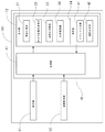
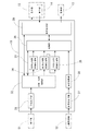
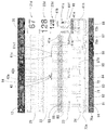
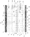
- FIG. 1 It is a block diagram explaining the structure of the fetal heart rate variability monitoring apparatus of one Embodiment of this invention. It is a block diagram explaining the structure of the processing part of the heart rate variability monitoring apparatus of the fetus shown in FIG. It is a front view of the display part of the fetal heart rate variability monitoring device, and is the figure which shows the display example during measurement of the information such as the fetal heart rate of a fetus. It is a front view of the display part of the heart rate variability monitoring device of the fetus which concerns on the 1st modification of the said embodiment. It is a front view of the display part of the heart rate variability monitoring device of the fetus which concerns on the 2nd modification of the said embodiment.
- FIG. 1 is a block diagram illustrating a configuration of a fetal heart rate variability monitoring device 101 (hereinafter, may be referred to as a monitoring device 101) of the present embodiment
- FIG. 2 is a block diagram illustrating a configuration of a processing unit 11 of the monitoring device 101. It is a block diagram to be done.
- FIG. 3 is a front view (a view showing a display screen) of the display unit 12 of the monitoring device 101.
- the monitoring device 101 of the present embodiment transmits from the device main body 10, the detection unit 51 connected to the device main body 10, and the delivery monitoring device (not shown). It is provided with an information acquisition unit 52 for acquiring the obtained information.
- the delivery monitoring device is provided with a labor transducer, an ultrasonic transducer, and the like (both not shown) attached to the abdomen of the mother.
- the apparatus main body 10 includes a processing unit 11 including a computer that arithmetically processes signals acquired from the detection unit 51 and the information acquisition unit 52, and various types of mothers and fetuses obtained by the processing unit 11.
- a display unit 12 (see FIG. 3) for displaying information is provided.
- the detection unit 51 connected to the device main body 10 is a sensor for detecting four pieces of information: a maternal electrocardiogram signal, a fetal bioelectric signal, a maternal heart rate, and a fetal heart rate.
- the detection unit 51 is composed of a plurality of abdominal electrodes and a plurality of chest electrodes, each of which is attached to the mother's body.
- the abdominal electrodes attached to the abdomen of the mother have various signals such as a maternal electrocardiogram signal generated from the maternal heart, a uterine electromyogram signal, a maternal electromyogram signal, and a fetal bioelectric signal generated from the fetal fetal heart in the mother. Detects a composite biopotential signal.
- the chest electrodes attached to the chest of the mother detect maternal electrocardiogram signals that do not include fetal bioelectric signals.
- the labor transducer connected to the delivery monitoring device is, for example, a pressure-sensitive sensor that detects a pressure increase caused by the expansion and compression of the mother's abdomen during uterine contraction.
- the ultrasonic transducer connected to the delivery monitoring device is, for example, an ultrasonic sensor for detecting the heartbeat of the fetus by the ultrasonic Doppler method. The pressure change detected by the labor transducer and the heartbeat of the fetus detected by the ultrasonic transducer are converted into electric signals and sent to the processing unit 11 of the apparatus main body 10 via the information acquisition unit 52.
- Each signal detected by the detection unit 51 and a signal input to the information acquisition unit 52 are sent to the processing unit 11 of the apparatus main body 10 as shown in the block diagram of FIG. 1, and these signals are sent to the processing unit 11 in the processing unit 11.
- the monitoring device 101 of the present embodiment employs the electrocardiogram signal processing method described in Patent Document 2 (Japanese Patent No. 4590554), and the fetal bioelectric signal is extracted based on this electrocardiogram signal processing method.
- the processing unit 11 includes an acquisition processing unit 31, a separation / analysis processing unit 32, a maternal heart rate conversion processing unit 33, and a fetus.
- a heart rate conversion processing unit 34, an LTV and STV conversion processing unit 35, a storage unit 36, a digitization processing unit 37, an arithmetic processing unit 38, and a display processing unit 39 are provided.
- the signal detected by the detection unit 51 is sent to the acquisition processing unit 31, and is converted into data suitable for analysis by the separation / analysis processing unit 32 in the acquisition processing unit 31.
- signal processing such as signal amplification, AD conversion, or data section division for recording / storage processing is performed.
- the signal processed by the acquisition processing unit 31 is passed from the acquisition processing unit 31 to the separation / analysis processing unit 32.
- the separation / analysis processing unit 32 performs electrocardiogram signal processing, and the fetal bioelectric signal is extracted from the biopotential signal passed from the acquisition processing unit 31.
- the fetal bioelectric signal extracted by the separation / analysis processing unit 32 is passed from the separation / analysis processing unit 32 to the fetal heart rate conversion processing unit 34.
- the fetal heart rate conversion processing unit 34 the fetal heart rate is calculated by the interval change of the signal corresponding to the R wave obtained from the fetal bioelectric signal.
- the maternal electrocardiogram signal detected by the chest electrode of the detection unit 51 is passed from the separation / analysis processing unit 32 to the maternal heart rate conversion processing unit 33, and is obtained from the maternal electrocardiogram signal in the maternal heart rate conversion processing unit 33.
- the maternal heart rate is calculated from the change in wave interval.
- rhythm irregularity is approximately constant within an individual.
- noise tends to be faster than normal, when the heart rate variability is acquired, a significantly faster value is obtained. Therefore, if the heart rate of the mother or the fetus with irregular rhythm is simply calculated from the fetal bioelectric signal, the fetal heart rate may be unreliable. Further, if the noise is simply set and the noise is removed, the normal value is also removed, and in this case as well, the fetal heart rate becomes unreliable, and it becomes difficult to recognize the abnormality of the fetus.
- the separation / analysis processing unit 32 detects a function of detecting fluctuations in the fetal bioelectric signal, fetal heart rate, etc., arrhythmia, etc., based on the information stored in the storage unit 36 in advance. It is equipped with a function and a function to detect analysis errors.
- the detection unit 51, the acquisition processing unit 31, the separation / analysis processing unit 32, the maternal heart rate conversion processing unit 33, and the fetal heart rate conversion processing unit 34 of the processing unit 11 As a result, the fetal bioelectric signal, the fetal heart rate, the maternal electrocardiogram signal, and the maternal heart rate are acquired.
- the STV and LTV are used as fluctuation information regarding the fluctuation of the fetal heart rate from the fetal heart rate acquired by the fetal heart rate conversion processing unit 34 by the LTV and STV conversion processing unit 35. It is supposed to be detected.
- the calculation means in the present invention is configured by the LTV and the STV conversion processing unit 35.
- the STV in the present embodiment is a change having the fastest change and a high frequency among fetal heart rate baseline fine fluctuations, and generally means a change in fetal heart rate interval time or instantaneous fetal heart rate for each heart rate. ..
- LTV has a slower change and a lower frequency than STV, and can be visually recognized on the fetal heart rate diagram, and usually has a relatively gentle fetal heart rate baseline fine variation of 2 to 6 times per minute. Means.
- the LTV and STV conversion processing unit 35 tables when the fetal heart rate (FHR calculated value) calculated during the calculation period (for example, every 10 heartbeats) changes beyond the preset conditions. As shown in 1 and Table 2, the difference between the STV calculated value and LTV calculated value of the heartbeat acquired before that and the STV calculated value and LTV calculated value of the current heartbeat is added each time, and the STV in the calculation period is added. And LTV.
- FHR calculated value fetal heart rate
- Table 1 is a table showing a calculation method of STV (STV integrated value).
- STV STV integrated value
- the FHR calculated value of the heart rate 5 corresponding to the “FHR calculated value acquired in” is 135, the FHR calculated value of the heart rate 6 corresponding to the “current FHR calculated value” is 100, and the difference is ⁇ 35.
- the absolute value of the above difference is not added to the STV integrated value, and the previous FHR calculated value is not updated. More specifically, in calculating the STV integrated value of the heart rate 7 shown in Table 1, the FHR calculated value (135) of the heart rate 5 is used as the base instead of the FHR calculated value (100) of the heart rate 6 to calculate the heart rate 7. Contrast with the calculated FHR value (133).
- Table 2 is a table showing a calculation method of LTV (LTV integrated value).
- LTV LTV integrated value
- the current FHR calculated value changes in a direction different from the previously acquired FHR calculated value (for example, as shown in heartbeats 4 and 5 in Table 2, “previously acquired FHR calculated value”.
- the change direction of the heart rate 4 corresponding to is "Up” meaning an increase, and the FHR calculated value of the heart rate 5 corresponding to the "current FHR calculated value” decreases from 140 to 135)
- the LTV integration is performed. Do not add the absolute value (+5) of the above difference to the value.
- the difference between the current FHR calculated value and the FHR calculated value acquired before that is a predetermined amount (for example, ⁇ 26 bpm) or more (for example, as shown in heartbeats 5 and 6 in Table 2, “before that”.
- the FHR calculated value of the heart rate 5 corresponding to the “FHR calculated value acquired in” is 135, the FHR calculated value of the heart rate 6 corresponding to the “current FHR calculated value” is 100, and the difference is ⁇ 35.
- the absolute value of the above difference is not added to the LTV integrated value, and the previous FHR calculated value is not updated. More specifically, when calculating the LTV integrated value of heart rate 7 shown in Table 2, the heart rate 7 is calculated based on the FHR calculated value (135) of heart rate 5 instead of the FHR calculated value (100) of heart rate 6. Contrast with the calculated FHR value (133).
- the STV integrated value and the LTV integrated value are reset every 10 heartbeats as shown in heartbeats 1 and 11 in Tables 1 and 2. It is supposed to be.
- the calculation period of STV and LTV may be calculated not based on the heart rate but, for example, every predetermined time (for example, every minute). In this case, since the STV integrated value and the LTV integrated value are reset at predetermined time intervals, the STV and LTV are calculated at predetermined time intervals (for example, every minute).
- the STV and LTV for the calculation period (every 10 heartbeats or every minute in this embodiment) calculated by such a method are stored in the storage unit 36.
- STV and LTV are calculated by the above method, but the present invention is not limited to this, and for example, “Medical Electronics and Bionics” Vol. 23, No. 1 (February 1985). It may be calculated from the definition formula shown in Table 1 on page 22 of "About the identity of various vionics regarding fetal heartbeat".
- the signals related to the pressure change detected by the labor transducer are digitized as shown in the block diagram of the processing unit 11 shown in FIG.
- signal processing such as signal amplification, AD conversion, or data classification for recording / storage processing is performed.
- the signal processed by the quantification processing unit 37 is passed from the quantification processing unit 37 to the arithmetic processing unit 38, and the arithmetic processing unit 38 calculates the labor pain intensity corresponding to 0 to 100. Then, the calculated labor pain intensity is recorded in the storage unit 36.
- the signal related to the fetal heartbeat detected by the ultrasonic transducer is also signal-amplified, AD-converted or AD-converted by the digitizing processing unit 37.
- the fetal heart rate is calculated by the arithmetic processing unit 38, and the fetal heart rate is stored in the storage unit 36.
- the fetal heart rate obtained via the information acquisition unit 52 is different from the fetal heart rate (fetal heart rate calculated by the fetal heart rate conversion processing unit 34) obtained via the detection unit 51. ..
- the signal input from the delivery monitoring device to the information acquisition unit 52 is signal-processed by the digitization processing unit 37, and the labor intensity and the fetal heart rate are calculated by the arithmetic processing unit 38.
- an external device such as a delivery monitoring device has a processing unit having the same functions as the digitizing processing unit 37 and the arithmetic processing unit 38, and the labor pain intensity calculated in the external device is obtained.
- information on the fetal heart rate may be input to the information acquisition unit 52 of the monitoring device 101.
- the processing unit 11 of the monitoring device 101 may not include the digitizing processing unit 37 and the arithmetic processing unit 38.
- the fetal bioelectric signal, fetal heart rate, maternal electrocardiogram signal, maternal heart rate, STV and LTV, and labor intensity recorded in the storage unit 36 are sent to the display processing unit 39.
- the display processing unit 39 performs drawing processing based on this information, and performs a maternal electrocardiogram (maternal electrocardiogram waveform) based on the maternal electrocardiogram signal, a fetal bioelectric signal diagram (fetal bioelectric signal waveform) based on the fetal bioelectric signal, and a fetal.
- Information about a fetal heart rate chart based on heart rate and a heart rate variability chart based on STV and LTV is created. As shown in FIGS.
- such information is displayed on the display unit 12 as a maternal electrocardiogram 21, a fetal bioelectric signal diagram 22, a fetal heart rate diagram 23, and a heart rate variability diagram 24.
- the heart rate variability diagram 24 is displayed in the labor intensity diagram based on the labor intensity, and is superimposed on the labor intensity curve (omitted in FIG. 3).
- the display processing unit 39 and the display unit 12 of the processing unit 11 provide a maternal electrocardiogram 21, a fetal bioelectric signal diagram 22, a fetal heart rate diagram 23, and a heart rate variability diagram 24.
- Information of STV and LTV in an arbitrary period designated by the user is also displayed separately, and the display processing unit 39 and the display unit 12 constitute the display means and the notification means of the present invention.
- the length of the arbitrary period is set to 1 minute in advance, but the set length (time) can be arbitrarily changed by the user.
- the processing method in the detection unit 51 and the processing unit 11 used in the present embodiment is an example, and in the present embodiment, the measurement / calculation methods of the maternal electrocardiogram signal, the fetal bioelectric signal, and the fetal heart rate are particularly described. It is not limited. Further, in the present embodiment, the detection unit 51 is used as the detection means by the external measurement method, but it is also possible to use the detection means by the internal measurement method, and among the detection means by the outer measurement method, the present embodiment. It is also possible to use a different detection means. Similarly, for the delivery monitoring device, various detection means can be used regardless of the distinction between the internal measurement method and the external method.
- information such as a maternal electrocardiogram signal and a fetal bioelectric signal is acquired by using the signal detected by the detection unit 51, and from the obtained maternal electrocardiogram signal and the fetal bioelectric signal.
- the method for obtaining the maternal heart rate and the fetal heart rate is not limited to this.
- the detection unit 51 it is possible to use a detection means capable of directly acquiring the maternal heart rate and the fetal heart rate by directly attaching electrodes or the like to the mother and the fetus.
- the display unit 12 is a touch panel type display (monitor) having an input function (operation function) as well as a display function for displaying information on the mother and the fetus.
- a maternal electrocardiogram 21 shows the waveform of the maternal electrocardiogram signal
- the fetal bioelectric signal FIG. 22 shows the waveform of the fetal bioelectric signal
- the fetal heart rate FIG. 23 shows the fetal heart rate over time.
- the curve TS is displayed, and the heart rate variability FIG.
- the fetal heart rate curve BS shows the externally input fetal heart rate over time are simultaneously displayed in FIG. 23.
- the horizontal axis is the time axis and the vertical axis is the numerical axis of each index.
- the horizontal axis display width (time range) in the maternal electrocardiogram 21 and the fetal bioelectric signal FIG. 22 is shorter than the horizontal axis display width (time range) in the fetal heart rate FIG. 23, and the fetal heart rate FIG. 23 shows. It is about 1/10 to 1/1000 (preferably 1/20 to 1/100), and therefore the display magnification is about 10 times to 1000 times (preferably 20 times to 100 times).
- the display width of the fetal heart rate FIG. 23 is set to a dozen minutes, while the display width of the maternal electrocardiogram 21 and the fetal bioelectric signal FIG. 22 is set to a dozen seconds. Thereby, in the maternal electrocardiogram 21 and the fetal bioelectric signal FIG. 22, the maternal electrocardiogram waveform and the fetal bioelectric signal waveform can be displayed in more detail.
- the information in the fetal heart rate diagram 23 and the heart rate variability diagram 24 is the latest information at the right end (right end on the horizontal axis) of FIG. Further, the display screen of the display unit 12 is provided with a recording time display area 26 for displaying the recording time so that the latest time (the time at the right end of FIG. 3 in the fetal heart rate FIG. 23) is displayed. It has become.
- the fetal heart rate (fetal heart rate conversion processing unit 34) calculated based on the fetal bioelectric signal detected by the detection unit 51 is displayed.
- a fetal heart rate digital display area 22d for digitally displaying the calculated fetal heart rate) is provided, and the digitally displayed fetal heart rate is displayed together with the waveform of the fetal bioelectric signal on one screen of the display unit 12. You can check at the same time.
- a maternal heart rate digital display area 21d for digitally displaying the maternal heart rate is provided, and the mother body is displayed on one screen of the display unit 12.
- the digitally displayed maternal heart rate can be confirmed at the same time.
- the fetal heart rate calculated based on the signal input to the information acquisition unit 52 separately from the fetal heart rate digital display area 22d.
- a fetal heart rate digital display area 23d for digitally displaying (fetal heart rate calculated by the digitization processing unit 37 and the arithmetic processing unit 38) is provided, and the fetal heart rate and external input calculated from the fetal bioelectric signal are provided. It is possible to check the fetal heart rate at the same time. As a result, even if one of the two fetal heart rates is temporarily not digitally displayed, the user can continue to use the fetal heart rate if the other fetal heart rate is digitally displayed. Can be confirmed.
- a plurality of screens can be switched and displayed on the display screen of the display unit 12.
- the display unit 12 includes an operation unit 14 having an event input unit 41 and a period designation unit 42. It is configured so that the user can perform various operations by operating (for example, pressing or touching) the operation switch displayed on the screen of the display unit 12.
- the event input unit 41 is, for example, an event recording button 41a to 41f composed of six icons arranged in the lower right portion of the display unit 12 shown in FIG. 3, and a window 41h arranged below the event recording buttons 41a to 41f. And.
- the event input unit 41 receives input operations from the user and also receives input from the user regarding various event information such as changing the position of the mother's body and giving vibration to wake up the sleeping fetus in the mother's body. It sometimes has a function of sending information about the input to the display processing unit 39.
- the information sent to the display processing unit 39 is drawn by the display processing unit 39 and sent to the display unit 12 again, or is stored (recorded) in the storage unit 36.
- the type of the event recording button input and operated by the user and the time when the event recording button is input and operated are linked and displayed.
- the types and operation times of these event recording buttons are sequentially displayed in chronological order from the upper part to the lower part of the window 41h.
- the event recording buttons 41a to 41f will be specifically described.
- the event recording button 41a shown in FIG. 3 is an icon representing a change of position of the mother body, and the event recording button 41b is for waking up a sleeping fetus in the mother body.
- the event recording button 41c is an icon representing the transmission of a signal that gives vibration
- the event recording button 41c is an icon representing a marker for arranging at the starting point of an arbitrary period for calculating STV and LTV
- the event recording button 41d supplies oxygen to the mother body.
- the event recording button 41e is an icon representing a blood transfusion to the mother
- the event recording button 41f is an icon representing a failure of the detection unit 51.
- the user moves (drag) the target event recording buttons 41a to 41f to the upper side of the fetal heart rate FIG. 23 while pressing the target event recording buttons 41a to 41f with a finger or a stylus, and releases the finger or the stylus at a desired position ( (Drop), the display processing unit 39 performs drawing processing, and event information (for example, the simple event recording button 61c shown in FIG. 3) is displayed on the upper side of the fetal heart rate FIG. 23.
- event information for example, the simple event recording button 61c shown in FIG. 3
- the simple event recording button 61c is displayed on the upper side of the fetal heart rate diagram 23. Further, starting from the position (time) where the simple event recording button 61c is arranged, the LTV and STV conversion processing unit 35 calculates the LTV and STV for an arbitrary period (for example, 1 minute) from the start point, and the arbitrary LTV and STV are displayed along with the average fetal heart rate over the period. The detection of the drag and drop operation (movement operation) is executed by the event input unit 41.
- the event input unit 41 detects a movement operation from the position where the event recording button 41c is displayed (first position) to the position on the fetal heart rate FIG. 23 (second position), the movement operation is performed. It has a function of designating an arbitrary period starting from the end position (that is, the second position) of. That is, the event input unit 41 corresponds to the designated period input unit of the present invention.
- the bar 61c1 extending in the lateral direction along the time axis of the fetal heart rate FIG. 23 is configured to be displayed as information indicating an arbitrary period.
- the bar 61c1 is displayed with a length corresponding to the length of an arbitrary period specified by the user. By confirming the positions of the start point and the end point of the bar 61c1, the user can clearly recognize the arbitrary period on the fetal heart rate FIG. 23. Further, the average value of the fetal heart rate, STV and LTV in an arbitrary period indicated by the bar 61c1 are displayed below the bar 61c1.
- the display unit 12 is a touch panel type display, and the case where the drag and drop operation is performed has been described as an example, but the present invention is not limited to this.
- the display unit is a type of display that displays a pointer on the screen
- the target event recording button is selected with the pointer
- the desired position on the fetal heart rate diagram is selected with the pointer.
- Event information can be displayed on the upper side of the fetal heart rate diagram.
- the display unit is a touch panel type display, if it has a pointer display function, for example, after pressing the target event recording button with a finger or a stylus, a desired fetal heart rate diagram is desired. By pressing the position with a finger or a stylus, event information (simple event recording button) can be displayed on the upper side of the fetal heart rate diagram.
- various selection buttons 81 to 88 are arranged at the bottom of the display unit 12 shown in FIG.
- the selection button 81 is a button for displaying the TOP screen
- the selection button 82 is a button for ending the playback.
- the selection button 83 is a marker button, and is a button on which a marker can be placed on the fetal heart rate FIG. 23 or the like by selecting the selection button 83.
- the selection button 84 is a capture button, and is a so-called screenshot button that converts the screen displayed on the display unit 12 at the time when the selection button 84 is selected into a captured image.
- the simple event button 64 indicating the capture is displayed on the fetal heart rate FIG. 23.
- the selection button 85 is a button for switching the display height of the waveform
- the selection button 86 is a button used after the screen is switched by the selection button 88.
- the selection button 87 is an analysis waveform button for displaying the analyzed waveform
- the selection button 88 is a switching button for switching the screen.
- event information indicating the occurrence of the analysis error or the like is automatically displayed in the fetus of the display unit 12.
- the heart rate is displayed in FIG. 23.
- the information is stored (recorded) in the storage unit 36 and sent to the display processing unit 39, drawn by the display processing unit 39, and then displayed.
- Fetal heart rate of part 12 is displayed in FIG. 23.
- STV and LTV calculated at a preset time interval are displayed each time STV and LTV are calculated.
- the STV and LTV are displayed in a line graph format in different colors (for example, blue and red).
- the time interval may be stored in the storage unit 36 in advance, or may be set by the user.
- the display unit 12 can display not only the maternal electrocardiogram 21, the fetal bioelectric signal diagram 22, the fetal heart rate diagram 23, and the heart rate variability diagram 24 based on various information processed in real time, but also the storage unit has already been stored. It is also possible to call up the recorded information stored in 36 and display the maternal electrocardiogram 21, the fetal bioelectric signal diagram 22, the fetal heart rate diagram 23, and the heart rate variability diagram 24 based on the accumulated various information.
- a scroll bar 71 showing the information storage time from the start of recording is provided at the lower part of the fetal heart rate FIG. 23 of the display unit 12 shown in FIG. 3, and the fetal heart rate FIG. 23 of the display unit 12 shows.
- Information within the period surrounded by the scroll frame 72 on the scroll bar 71 is displayed.
- the fetal heart rate FIG. 23 when the information is accumulated beyond the period that can be displayed on the screen, a part of the information accumulated in the storage unit 36 is displayed. ..
- the information of the period not displayed in the fetal heart rate FIG. 23 on the screen is obtained by moving the scroll frame 72 in the left-right direction of the screen along the scroll bar 71.
- Information on the period can be displayed in the fetal heart rate FIG. 23.
- the scroll frame 72 can be moved to an arbitrary position on the scroll bar 71 by tracing the screen of the display unit 12 with a finger, but in addition, the period return buttons 73a arranged on the left and right sides of the scroll bar 71. And by operating (pressing, touching) the period feed button 73b, the scroll frame 72 is moved on the period adjacent to the current display period, and the fetal heart rate, LTV, and STV information in that period are displayed on the fetal heart rate diagram. 23 and the heart rate variability FIG. 24 can be displayed.
- the scroll frame 72 moves to the right side, and the fetus in the period adjacent to the right side of the current display period (a period later than the current time and newer information than the current time).
- Information on heart rate, LTV, and STV is displayed in fetal heart rate diagram 23 and heart rate variability diagram 24.
- the scroll frame 72 moves to the left side, and the period adjacent to the left side of the current display period (the period before the current time and older than the current time).
- Information on the fetal heart rate, LTV, and STV is displayed in the fetal heart rate diagram 23 and the heart rate variability diagram 24.
- the scroll frame 72 is further moved to the left side, and the fetal heart rate, LTV, and STV information at that position is displayed in the fetal heart rate diagram 23 and the heart rate variability diagram 24. be able to.
- the fetal heart rate, LTV, and STV information for each period surrounded by the scroll frame 72 are displayed in the fetal heart rate diagram 23 and the heart rate variability diagram 24. Can be displayed in order.
- a period during which a shorter position (designated period) within the display time axis displayed in the fetal heart rate FIG. 23 can be specified on the fetal heart rate FIG. 23 during reproduction.
- a designated portion 42 is provided.
- the short period at this time is, for example, several seconds.
- the fetal bioelectric signal waveform within the designated period designated by the period designation unit 42 is displayed.
- the fetal bioelectric signal waveform is continuously displayed including the period before and after (left and right) of this region 42b, that is, the period before and after adjacent to the designated period, and the background color is displayed in the region 42b and the region other than the region 42b. Is changing. This allows the user to clearly discriminate between the fetal bioelectric signal in the designated period and the fetal bioelectric signal in another period.
- the region 42a is also displayed in the maternal electrocardiogram 21, and since the background color is changed between the region 42a and the region other than the region 42a, the maternal electrocardiogram signal during the specified period. The user can clearly distinguish the difference between the signal and the maternal electrocardiogram signal in other periods.
- the maternal electrocardiogram 21 and the fetal bioelectric signal FIG. 22 always display information in the same time range.
- the period designation unit 42 is a marker having a vertical line displayed in a width of 1 pixel to several pixels on the screen, and a time corresponding to this width is designated as a designated period, and the maternal electrocardiogram 21 and the fetal bioelectric signal diagram 22 In, by regions 42a, 42b.
- the width of the period designation unit 42 corresponds to 1 second, for example, 1 second is designated as the designated period.
- the width is 100 times the width of the period designation unit 42. Surrounded by regions 42a, 42b.
- the scroll bar 71 shows information on the entire measurement time (for example, several hours), and the fetal heart rate FIG. 23 shows information on the time surrounded by the scroll frame 72 (for example, 15 minutes).
- the maternal electrocardiogram 21 and the fetal bioelectric signal FIG. 22 show enlarged information for a shorter time (for example, 10 seconds) than the fetal heart rate FIG. 23, and the designated period designated by the period designation unit 42. (For example, 1 second) is indicated by regions 42a, 42b.
- Areas 42a and 42b are used as means for identifiablely displaying the fetal bioelectric signal within the designated period designated by the period designation unit 42 and the fetal bioelectric signal in another period adjacent to the designated period.
- the fetal bioelectric signal is displayed by a frame line surrounding a part of FIG. 22, and the line showing the waveform of the fetal bioelectric signal within the specified period.
- Various means such as changing the color to a color different from other periods and changing the thickness of the waveform of the fetal bioelectric signal can be adopted.
- the fetal bioelectric signal and the maternal electrocardiogram signal in the designated period can be displayed on the display unit 12, and the user can display the designated period. It is easy to check.
- a simple icon or the like corresponding to the simple event recording button 61c or the like displayed on the fetal heart rate FIG. 23 is displayed, and the user can check the presence or absence of the event information on the scroll bar 71. Can be easily confirmed at. Therefore, the user can easily recognize the correlation between the event information and the information in the fetal heart rate FIG. 23.
- An event display return button 75a and an event display feed button 75b are arranged on the left and right sides of the scroll bar 71, and by operating (pressing or touching) the event display return button 75a and the event display feed button 75b. , The scroll frame 72 can be moved from the position where the scroll frame 72 is currently arranged to the period in which the event information at the nearest position is recorded. Then, information on the fetal heart rate and labor intensity during this period can be instantly displayed on the fetal heart rate FIG. 23.
- the fetal heart rate FIG. 23 is displayed with the event information arranged at the position closest to the current scroll frame 72 on the right side of the screen as the center of the display period. ..
- the event display feed button 75b is subsequently operated, the fetal heart rate FIG. 23 is displayed with the event information on the right side of the screen as the center of the display period from the event information arranged at the center position of the current display period.
- the event display return button 75a is operated, the fetal heart rate FIG. 23 is displayed with the event information arranged at the position closest to the current scroll frame 72 on the left side of the screen as the center of the display period.
- the event information can be easily accessed by operating the event display return button 75a and the event display feed button 75b.
- the above-mentioned operation unit 14 includes an event display return button 75a and an event display feed button 75b that can be operated on the display unit 12 in addition to the event input unit 41 and the period designation unit 42.
- the display unit 12 is configured by a touch panel type display having both a display function and an input function (operation function), but the present invention is not limited to this, and for example, an independent operation is performed beside the display unit 12.
- the part may be arranged. In this case, the user can easily perform the operation while checking the display unit 12.
- the operation of the monitoring device 101 will be described.
- the signal acquired from the detection unit 51 and the signal input from the information acquisition unit 52 are processed by the processing unit 11, and the display unit 12 shows in FIG.
- the fetal heart rate diagram 23 and the heart rate variability diagram 24 are displayed as described above.
- the display unit 12 includes a fetal bioelectric signal FIG. 22 for displaying the waveform of the fetal bioelectric signal and a maternal electrocardiogram for displaying the waveform of the maternal electrocardiogram signal, together with the fetal heart rate diagram 23 and the heart rate variability diagram 24. 21 and are displayed at the same time.
- the information processed in real time is displayed on the display unit 12. This information is displayed along with the time axis and is updated sequentially with the passage of time.
- the information in the fetal heart rate diagram 23 and the heart rate variability diagram 24 is the latest information at the right end of FIG. Further, in the recording time display area 26, the latest information, the time at the time of measurement, is displayed, and the information is updated with the passage of time.
- the information of the maternal electrocardiogram 21 and the fetal bioelectric signal FIG. 22 is updated in order from the left end side to the right end side of FIG. 3 every unit time, and when the update portion reaches the right end, it returns to the left end and is updated.
- Fetal heart rate The maternal heart rate and fetal heart rate corresponding to the time at the right end of FIG. 23 are displayed as numerical values in the maternal heart rate digital display area 21d and the fetal heart rate digital display area 22d.
- the update of the information in the maternal electrocardiogram 21 and the fetal bioelectric signal FIG. 22 is not limited to this, and the screen may be scrolled with the passage of time.
- the event icon of the event information corresponding to the operated event recording buttons 41a to 41f is displayed on the fetal heart rate FIG. 23. These event information are stored (stored) in the storage unit 36 together with the occurrence time.
- the user specifies an arbitrary period for recognizing the fluctuation information in the fetal heart rate FIG. 23, and the average heart rate, STV, and LTV are used as the fluctuation information in the arbitrary period. Is notified, so that the situation of the fetus can be easily determined at an arbitrary period.
- STV and LTV are calculated at preset time intervals, and each time the STV and LTV are calculated, they are displayed as a graph as a heart rate variability diagram 24. Therefore, changes over time of STV and LTV can be recognized, and the fetus can be recognized. The situation can be judged more easily.
- the user can specify an arbitrary period after recognizing the change over time of at least one of STV and LTV, it is possible to more easily determine the condition of the fetus. Specifically, when the user has doubts about the STV or LTV values calculated and displayed at a preset time interval, the user has a questionable area (for example, noise occurs in the fetal heart rate). By setting an arbitrary period excluding the region), appropriate STV and LTV can be obtained, and the condition of the fetus can be determined more easily.
- the LTV and STV calculated at predetermined time intervals are displayed on the heart rate variability diagram 24, but the present invention is not limited to this.
- FIG. 4 is a front view of the display unit 12 of the monitoring device 101 according to the first modification of the embodiment (in this first modification, the common elements with the embodiment are designated by the same reference numerals and described. The same applies to each of the following modifications).
- the first modification as shown in FIG. 4, only the LTV calculated at predetermined time intervals is displayed in the heart rate variability FIG. 24.
- the LTV and the STV conversion processing unit 35 need only calculate the LTV for each predetermined time, but the STV may also be calculated.
- FIG. 5 is a front view of the display unit 12 of the monitoring device 101 according to the second modification of the above embodiment.
- the second modification as shown in FIG. 5, only the STV calculated at predetermined time intervals is displayed in the heart rate variability FIG. 24.
- the LTV and the STV conversion processing unit 35 need only calculate the STV for each predetermined time, but the LTV may also be calculated.
- the STV and LTV in the heart rate variability diagram 24 are displayed in a line graph format, but the present invention is not limited to this.
- FIG. 6 is a front view of the display unit 12 of the monitoring device 101 according to the third modification of the above embodiment.
- the heart rate variability FIG. 24 displays STV and LTV in a vertical bar graph format.
- the STV and LTV in the arbitrary period are the STV in the other period.
- the STV and LTV in the other period are the STV in the other period.
- the STV and LTV calculated for each predetermined time are displayed in light orange and light blue, respectively, and the STV and LTV in an arbitrary period are displayed in dark orange and dark blue (reference numeral 61c3 in FIG. 6). Therefore, the user can easily recognize the STV and LTV in the arbitrary period on the heart rate variability diagram 24 as well as the numerical values of the STV and LTV displayed below the bar 61c1 indicating the arbitrary period.
- the STV or LTV in the arbitrary period is the STV or LTV in the other period. It may be displayed in a different color from.
- the information indicating an arbitrary period in the fetal heart rate chart is not limited to bar 61c1.
- an arbitrary period may be divided and displayed on the fetal heart rate diagram 23, or the color of the fetal heart rate curve or the background color of the fetal heart rate diagram in the arbitrary period may be different from those other than the arbitrary period. It may be displayed. Further, a marker or the like may be displayed only at the start point and the end point of an arbitrary period.
- the labor pain intensity is not displayed on the display unit 12, but the labor pain intensity may be displayed on the display unit 12.
- FIG. 7 is a front view of the display unit 12 of the monitoring device 101 according to the fourth modification of the above embodiment.
- the heart rate variability FIG. 24 displays STV and LTV in a vertical bar graph format, and also displays the labor intensity curve JK (see FIG. 7). Therefore, the fetal heart rate, the maternal heart rate, the maternal electrocardiogram signal, the fetal bioelectric signal, the STV and the LTV, as well as the maternal labor intensity can be acquired together, and the user can recognize the fetal condition judgment in more detail.
- the size of the window 41h displayed in the lower right portion of the display unit 12 may be changeable.
- FIG. 8 is a front view of the display unit 12 of the monitoring device 101 according to the fifth modification of the above embodiment.
- the size of the window 41h can be increased as shown in FIG.
- the window 41h expands the display range. It is enlarged and displayed. As a result, the user can more easily recognize the various event information and the time when the event information is input.
- the average heart rate of the fetus, STV, and LTV within an arbitrary period are notified as information (variation information) regarding the heart rate variability of the fetus, but the present invention is not limited to this.
- FIG. 9 is a front view of the display unit 12 of the monitoring device 101 according to the sixth modification of the above embodiment.
- information regarding the heart rate variability of the fetus
- the average heart rate, the maximum heart rate, the minimum heart rate, and the difference between the maximum heart rate and the minimum heart rate within an arbitrary period are notified. ..
- the frames 91, 92, and 93 surrounding the fetal heart rate curve at an arbitrary period in FIG. 23 are displayed.
- the width of the frames 91, 92, 93 is set according to the length of the arbitrary period. That is, the position at the left end of each frame 91, 92, 93 corresponds to the start point of the arbitrary period, and the position at the right end of each frame 91, 92, 93 corresponds to the end point of the arbitrary period.
- the height of each frame 91, 92, 93 depends on the height from the minimum value to the maximum value of the fetal heart rate in the fetal heart rate curve (difference between the maximum heart rate and the minimum heart rate) in an arbitrary period. Is set. In FIG.
- the heights of the frames 91, 92, and 93 are set as the heights from the minimum value to the maximum value of the fetal heart rate in an arbitrary period.
- the difference between the maximum heart rate and the minimum heart rate is "4", "10", and "94" in order from the left side of the screen. .. Therefore, the height of the frame 91 is the smallest, and the height of the frame 93 is the largest.
- the larger the difference between the maximum value and the minimum value of the fetal heart rate in an arbitrary period the larger the height of the above frame. Therefore, the user can see the size of the frame displayed in FIG.
- the fetal heart rate It is possible to recognize that the heart rate variability of the fetus is large just by visually recognizing, and it is possible to judge the situation of the fetus more appropriately. Further, since the widths of the frames 91, 92, and 93 correspond to the length of the arbitrary period, the user can easily recognize the length of the arbitrary period as well as the magnitude of the fetal heart rate fluctuation.
- the frame is not limited to the above frame, and for example, a quadrangle filled with a color or shading pattern different from other areas. It may be displayed with.
- the height of the frame 93 shown on the right side of the drawing is set to be smaller than the height of the fetal heart rate baseline. This is because the frame 93 is set without including the fetal heart rate determined to be noise by the separation / analysis processing unit 32.
- the noise determination by the separation / analysis processing unit 32 is performed by a fixed method. As a result, the user can visually confirm that the height of the frames 91, 92, 93, that is, the fluctuation of the fetal heart rate is calculated only by the noise-removed fetal heart rate.
- the bar 61j1 is configured to be displayed in a different manner according to the value of the fluctuation information.
- the three bars 61j1 shown in FIG. 9 are displayed in yellow-green, blue, and red in order from the left side of the drawing.
- the color of each bar 61j1 corresponds to the magnitude of the difference between the maximum and minimum heart rates of the fetus for any period in which each bar 61j1 is located.
- the bar 61j1 is displayed in a different color (aspect) according to the value of the fluctuation information (difference between the maximum heart rate and the minimum heart rate of the fetus), so that the user fluctuates according to the display mode of the bar 61j1.
- the urgency of the information value can be recognized, and the situation of the fetus can be reliably judged.
- the event recording button is arranged outside the display area of the fetal heart rate FIG. 23 (the right end of the screen of the display unit 12), but the present invention is not limited to this.
- the event recording buttons 41a to 41f are popped up, and when the event recording button 41c is selected from the pop-ups, an arbitrary period is set. It may be.
- the event recording button 41c is selected after the user has selected the desired position on the fetal heart rate FIG. 23. That is, in the present invention, the desired position on the fetal heart rate FIG. 23 and the selection order of the event recording button 41c do not matter.
- the various modes shown in the above modified examples can be combined, and the frames 91 to 93 may be displayed in the first to fifth modified examples. It is also possible to change the color of the bar according to the value of the fluctuation information. Further, in addition to changing the color of the bar, the color of the numerical value such as the fetal heart rate displayed below the bar may be changed and displayed.
- the fetal heart rate variability monitoring device 101 is configured such that the signal acquired by the delivery monitoring device is input via the information acquisition unit 52, but is not limited to this, and is attached to, for example, the abdomen of the mother. It may have a detection means corresponding to a labor pain transducer and an ultrasonic transducer. In this case, the fetal heart rate variability monitoring device 101 can also be used as a delivery monitoring device. That is, the display example of the display unit 12 can also be applied to the delivery monitoring device.
- the present invention can be used as a fetal heart rate variability monitoring device for monitoring fetal heart rate variability.
Landscapes
- Health & Medical Sciences (AREA)
- Life Sciences & Earth Sciences (AREA)
- Engineering & Computer Science (AREA)
- Cardiology (AREA)
- Public Health (AREA)
- Surgery (AREA)
- Veterinary Medicine (AREA)
- Physics & Mathematics (AREA)
- General Health & Medical Sciences (AREA)
- Biophysics (AREA)
- Pathology (AREA)
- Biomedical Technology (AREA)
- Heart & Thoracic Surgery (AREA)
- Medical Informatics (AREA)
- Molecular Biology (AREA)
- Animal Behavior & Ethology (AREA)
- Signal Processing (AREA)
- Physiology (AREA)
- Computer Vision & Pattern Recognition (AREA)
- Artificial Intelligence (AREA)
- Psychiatry (AREA)
- Measurement And Recording Of Electrical Phenomena And Electrical Characteristics Of The Living Body (AREA)
- Measuring Pulse, Heart Rate, Blood Pressure Or Blood Flow (AREA)
- Ultra Sonic Daignosis Equipment (AREA)
- Measuring And Recording Apparatus For Diagnosis (AREA)
Abstract
胎児の状況判断を容易に行うことができる胎児の心拍変動監視装置を提供する。 胎児の心拍変動監視装置(101)は、胎児心拍数を取得して、胎児心拍数を経時的に示す胎児心拍数図を表示する処理部(11)及び表示部(12)と、胎児心拍数からSTV及びLTVを算出するLTV及びSTV変換処理部(35)と、胎児心拍数図上の任意期間を指定可能なイベント入力部(41)と、を備える。処理部及び表示部は、イベント入力部により任意期間が指定されたときに、LTV及びSTV変換処理部により算出された任意期間におけるSTV及びLTVを報知する機能を備える。
Description
本発明は、胎児の心拍変動監視装置に関する。本願は、日本国において2019年4月10日に出願された特願2019-74960号に基づき優先権を主張し、その内容をここに援用する。
心拍は、心臓の洞房結節の発火周期で延髄の心臓血管中枢が1拍毎の発火周期を変えており、自律神経系や内分泌系による調整を受けている。心拍変動は単純な非侵襲的手法であり、心拍のR‐R’間(R波の間隔)ごとの変動を測定することにより、心臓の自律神経緊張の指標としている。
例えば、特許文献1には、胎児心拍数(FHR:fetal heart rate)の経時的変化を示す胎児心拍数曲線と、陣痛強度(子宮収縮圧)の経時的変化を示す母体陣痛曲線と、を記録紙に記録する分娩監視装置が記載されている。この分娩監視装置における表示部には、胎児心拍数がデジタル表示(数値表示)される胎児心拍数表示部と、陣痛強度がデジタル表示(数値表示)される陣痛強度表示部と、胎児心拍数基線がデジタル表示(数値表示)される胎児心拍数基線表示部とともに、一過性徐脈(早発、遅発、変動、遷延)に関する表示部、心拍数基線細変動(消失、減少、中等度、増加)に関する表示部や、警報サインが設けられている。このように、特許文献1には、胎児心拍数基線等の主な情報、及び緊急度等警告を分娩監視装置の表示部に表示することで、胎児の健康状態の判断のための高度な判読作業が不要となり、かつ医師の負担が軽減されることが記載されている。
このような従来の分娩監視装置における胎児心拍数の検出方法としては、破膜後に心電電極を直接胎児に装着して胎児の心電図を直接的に検出する内測法と、母体腹壁に装着した超音波トランスデューサ等によって胎児の心臓の動きを間接的に検出する外測法(超音波ドプラ法)とが活用されている。このうち、内測法は、破膜後(分娩時)に胎児に直接心電電極を装着することから、破膜前において使用することはできない。また、超音波トランスデューサを用いた超音波ドプラ法では、母体からのノイズが含まれることが多く、胎児心拍数を適切に検出することが難しかった。
一方、特許文献2には、母体に取り付けられた電極から検出される生体電位信号(腹部心電図信号)中に含まれる胎児心電図信号(胎児生体電気信号相当の信号)を抽出するための心電図信号処理方法及び心電図信号処理装置が記載されている。この特許文献2に記載されるように、胎児生体電気信号の有用性は広く認識されており、分娩時のみではなく、非観血方法により胎児生体電気信号を抽出するための方法が考えられている。このように、胎児生体電気信号の抽出が可能となれば、R‐R’間(R波の間隔)の正確な心拍数検知を行えるようになり、胎児心拍数の変動をbeat‐to‐beatで正確に把握できるようになると考えられる。
しかし、特許文献2に記載の胎児生体電気信号に基づいて胎児心拍数を算出し、胎児心拍数図を表示部に表示しても、医師が胎児心拍数図から肉眼で波形を見て、胎児の心拍変動を判断する必要があり、その波形の判断が医師により異なるおそれがある。この場合、特許文献1のように、所定範囲内の胎児心拍数基線から胎児心拍数基線細変動を定期的に表示するとしても、胎児の心拍変動を適切に評価できない場合がある。
本発明は、このような事情に鑑みてなされたもので、胎児の心拍変動を適切に評価して、胎児の状況判断を適切に行うことができる胎児の心拍変動監視装置を提供することを目的とする。
本発明の胎児の心拍変動監視装置は、胎児心拍数を取得して、前記胎児心拍数を経時的に示す胎児心拍数図を表示する表示手段と、前記胎児心拍数から胎児の心拍変動に関する情報である変動情報を算出する算出手段と、前記胎児心拍数図上の任意期間を指定可能な指定期間入力部と、前記指定期間入力部により前記任意期間が指定されたときに、前記算出手段により算出された前記任意期間における前記変動情報を報知する報知手段と、を備える。
本発明では、胎児心拍数図における変動情報を認識したい任意期間をユーザが指定することで、任意期間における変動情報が報知されるので、胎児の心拍変動を適切に評価でき、任意期間における胎児の状況判断を容易にできる。
なお、上記変動情報としては、胎児心拍数の変動(胎児心拍数曲線の経時的な振幅変動や周波数変動を含む)、胎児心拍数基線細変動を示す値(STVやLTV)の他、その値に応じて上記値の表示色を変更したり、その値に応じて警報音を変えたりすること等を含む。すなわち、上記報知とは、表示に限らず、音声出力を含む。
なお、STV(Short Term Variability)とは、胎児心拍数基線細変動のうち、変化が最も速くて周波数の高い変化であり、一般に胎児心拍間隔時間又は瞬時胎児心拍数の心拍ごとの変化分を意味する。また、LTV(Long Term Variability)とは、STVよりも変化が遅く周波数も低くて、胎児心拍数図上で肉眼的に認めることができ、通常1分間に2~6回の比較的緩やかな胎児心拍数基線細変動を意味する。
本発明の胎児の心拍変動監視装置の好ましい態様としては、前記算出手段は、予め設定された時間間隔でSTV及びLTVの少なくとも一方の値を算出し、前記表示手段は、逐次算出される前記値をグラフにより表示するとよい。
上記態様では、予め設定された時間間隔でSTV及びLTVの少なくとも一方の値が算出され、逐次STV及びLTVの少なくとも一方がグラフにより表示されることから、STV及びLTVの少なくとも一方の経時的な変化を認識でき、胎児の状況判断をより容易にできる。
また、STV及びLTVの少なくとも一方の経時的変化を認識した上で、任意期間を指定できるので、胎児の状況判断をより容易にできる。具体的には、予め設定された時間間隔で算出されて表示されたSTVやLTVの値に疑問を感じた場合に、ユーザは、疑問を感じた領域(例えば、胎児心拍数にノイズが生じている領域)を除外した任意期間を設定することで、適切な変動情報を取得でき、胎児の状況判断をより容易にできる。
本発明の胎児の心拍変動監視装置の好ましい態様としては、前記報知手段は、前記指定期間入力部により指定された前記任意期間を示す情報を、前記胎児心拍数図に対応させて前記表示手段により表示させるとよい。
上記態様では、任意期間を示す情報が胎児心拍数図に対応して表示されるので、胎児心拍数図における任意期間が明確となる。
上記態様では、任意期間を示す情報が胎児心拍数図に対応して表示されるので、胎児心拍数図における任意期間が明確となる。
本発明の胎児の心拍変動監視装置の好ましい態様としては、前記報知手段は、前記指定期間入力部により前記任意期間が指定されたときに、前記任意期間を示す情報とともに、前記任意期間における前記変動情報を前記胎児心拍数図の近傍に前記表示手段により表示させるとよい。
上記態様では、任意期間における変動情報を視認できることから、胎児の状況判断をより一層容易にできる。
上記態様では、任意期間における変動情報を視認できることから、胎児の状況判断をより一層容易にできる。
本発明の胎児の心拍変動監視装置の好ましい態様としては、前記報知手段は、前記変動情報の値に応じて、前記変動情報及び前記任意期間を示す情報の少なくとも一方を異なる態様で表示させるとよい。
上記態様では、変動情報の値に応じて変動情報及び任意期間を示す情報の少なくとも一方が異なる態様で表示されるので、ユーザは、その表示態様に応じて変動情報の値の緊急度を認識でき、確実に胎児の状況判断が可能となる。
上記態様では、変動情報の値に応じて変動情報及び任意期間を示す情報の少なくとも一方が異なる態様で表示されるので、ユーザは、その表示態様に応じて変動情報の値の緊急度を認識でき、確実に胎児の状況判断が可能となる。
本発明の胎児の心拍変動監視装置の好ましい態様としては、前記報知手段は、前記任意期間を示す情報を前記胎児心拍数図の時間軸に沿って前記任意期間に応じて延びるバーとして表示させるとよい。
上記態様では、任意期間を示す情報が胎児心拍数図の時間軸に沿って延びるバーとして表示されるので、胎児心拍数図における任意期間がより明確となる。
上記態様では、任意期間を示す情報が胎児心拍数図の時間軸に沿って延びるバーとして表示されるので、胎児心拍数図における任意期間がより明確となる。
本発明の胎児の心拍変動監視装置の好ましい態様としては、前記変動情報は、前記胎児心拍数の変動を示す情報を含み、前記報知手段は、前記胎児心拍数図の前記任意期間における胎児心拍数曲線を包含する領域を表示し、前記胎児心拍数図の縦軸方向における前記領域の大きさは、前記変動情報に応じて設定されるとよい。
上記態様では、任意期間における胎児心拍数曲線を包含する領域の大きさが変動情報に応じて設定されるので、ユーザは、当該領域の大きさを視認するだけで、胎児の心拍変動の大きさを認識でき、胎児の状況判断をより適切にできる。
本発明の胎児の心拍変動監視装置の好ましい態様としては、前記報知手段は、前記胎児心拍数図の前記任意期間における前記胎児心拍数曲線を囲う枠を表示し、前記枠の高さは、前記任意期間における前記胎児心拍数曲線内の前記胎児心拍数の最小値から最大値までの高さに応じて設定されるとよい。
上記態様では、任意期間における胎児心拍数の最大値と最小値との差が大きい程、上記枠の高さが大きくなることから、ユーザは、胎児心拍数図内に表示された枠の大きさを視認するだけで胎児の心拍変動が大きいことを認識でき、胎児の状況判断をより適切にできる。
本発明の胎児の心拍変動監視装置の好ましい態様としては、前記表示手段は、前記任意期間を設定するためのアイコンを表示し、前記指定期間入力部は、前記アイコン及び前記胎児心拍数図上の任意の位置が選択されたとき、当該任意の位置を前記任意期間の始点として前記任意期間を指定するとよい。
上記態様では、任意期間のアイコン及び胎児心拍数図上の任意の位置が選択されると、任意期間の始点が任意の位置とされるので、任意期間の設定を容易にできる。
上記態様では、任意期間のアイコン及び胎児心拍数図上の任意の位置が選択されると、任意期間の始点が任意の位置とされるので、任意期間の設定を容易にできる。
本発明の胎児の心拍変動監視装置の好ましい態様としては、前記表示手段は、前記アイコンを前記胎児心拍数図よりも外側に表示し、前記指定期間入力部は、前記アイコンの表示位置から、前記胎児心拍数図上の任意の位置までの移動操作を検知したとき、当該移動操作の終了位置を前記任意期間の始点として、前記任意期間を指定するとよい。
上記態様では、アイコンを移動させる(例えば、ドラッグ&ドロップする)だけで任意期間を設定できるので、任意期間の設定をさらに容易に行うことができる。また、移動操作の終了位置(例えば、ドロップ位置)が任意期間の始点となる構成であるため、アイコンを胎児心拍数図上で移動させながら任意期間の始点の位置を考慮することができ、より適切に任意期間を設定できる。
本発明によれば、胎児心拍数(胎児心拍数図)とともに、ユーザが所望する期間内の胎児の心拍変動を判断可能な指標を表示することで、胎児の状況判断を容易に行うことができる。
以下、本発明の胎児の心拍変動監視装置の実施形態について、図面を参照して説明する。図1は本実施形態の胎児の心拍変動監視装置101(以下、監視装置101という場合がある。)の構成を説明するブロック図であり、図2は監視装置101の処理部11の構成を説明するブロック図である。図3は、監視装置101の表示部12の正面図(表示画面を示す図)である。
[胎児の心拍変動監視装置の全体構成]
本実施形態の監視装置101は、図1に全体のブロック図を示したように、装置本体10と、この装置本体10に接続される検出部51と、図示を省略するが分娩監視装置から送信された情報を取得するための情報取得部52とを備える。分娩監視装置には、母体の腹部に取り付けられる陣痛トランスデューサや超音波トランスデューサ等(ともに図示せず)が設けられている。
本実施形態の監視装置101は、図1に全体のブロック図を示したように、装置本体10と、この装置本体10に接続される検出部51と、図示を省略するが分娩監視装置から送信された情報を取得するための情報取得部52とを備える。分娩監視装置には、母体の腹部に取り付けられる陣痛トランスデューサや超音波トランスデューサ等(ともに図示せず)が設けられている。
装置本体10は、図1のブロック図に示すように、検出部51及び情報取得部52から取得した信号を演算処理するコンピュータからなる処理部11と、処理部11において得られる母体及び胎児の各種情報を表示する表示部12(図3参照)とを備える。
装置本体10に接続される検出部51は、母体心電図信号、胎児生体電気信号、母体心拍数及び胎児心拍数の4つの情報を検出するためのセンサである。検出部51は、図示は省略するが、それぞれ母体に装着される複数の腹部電極と、複数の胸部電極とにより構成される。母体の腹部に取り付けられる腹部電極は、母体心臓から発生する母体心電図信号、子宮筋電図信号、母体筋電図信号及び母体内の胎児の胎児心臓から発生した胎児生体電気信号等、種々の信号が複合された生体電位信号を検出する。また、母体の胸部に取り付けられる胸部電極は、胎児生体電気信号を含まない母体心電図信号を検出する。
一方、分娩監視装置に接続される陣痛トランスデューサは、例えば、子宮収縮時に母体の腹部が拡張し圧迫されることで生じる圧力上昇を検出する感圧式のセンサである。同じく、分娩監視装置に接続される超音波トランスデューサは、例えば、超音波ドプラ法により胎児の心拍動を検出するための超音波センサである。陣痛トランスデューサによって検出された圧力変化及び超音波トランスデューサによって検出された胎児の心拍動は、それぞれ電気信号に変換され、情報取得部52を介して装置本体10の処理部11に送られる。
検出部51で検出される各信号及び情報取得部52に入力される信号は、図1のブロック図に示すように、装置本体10の処理部11に送られ、処理部11において、これらの信号を用いて、胎児生体電気信号が抽出される。本実施形態の監視装置101では、特許文献2(日本国特許第4590554号公報)に記載される心電図信号処理方法を採用しており、この心電図信号処理方法に基づき、胎児生体電気信号が抽出される。
より詳細には、図2の処理部11のブロック図に示すように、処理部11には、取込処理部31と、分離・解析処理部32と、母体心拍数変換処理部33と、胎児心拍数変換処理部34と、LTV及びSTV変換処理部35と、記憶部36と、数値化処理部37と、演算処理部38と、表示処理部39とが設けられている。検出部51で検出された信号は取込処理部31に送られ、取込処理部31において分離・解析処理部32での解析に適したデータに変換される。取込処理部31で行われるデータ変換処理について、具体的には、信号増幅、AD変換又は記録・保存処理のためのデータの区間分け等の信号処理が行われる。
取込処理部31で処理された信号は、取込処理部31から分離・解析処理部32に受け渡される。分離・解析処理部32では心電図信号処理が行われ、取込処理部31から受け渡された生体電位信号から胎児生体電気信号が抽出される。分離・解析処理部32にて抽出された胎児生体電気信号は、分離・解析処理部32から胎児心拍数変換処理部34に受け渡される。胎児心拍数変換処理部34では、胎児生体電気信号から得られるR波相当の信号の間隔変化により、胎児心拍数が算出される。検出部51の胸部電極で検出された母体心電図信号は、分離・解析処理部32から母体心拍数変換処理部33に受け渡され、母体心拍数変換処理部33において、母体心電図信号から得られるR波の間隔変化により、母体心拍数が算出される。これらの胎児生体電気信号、胎児心拍数、母体心電図信号及び母体心拍数は、記憶部36に記録される。
ここで、いわゆるリズム不整に代表される心拍増減幅は、個人内ではおよそ一定である。また、ノイズについては、正常に比べて速い数値が出る傾向があるため、心拍変動速度を取得すると突出して速い数値が出てしまう。このため、リズム不整の母体や胎児の心拍数を胎児生体電気信号から単に算出すると、信頼性の少ない胎児心拍数となるおそれがある。また、単に閾値を設定してノイズを除去すると、正常な値も除去することとなり、この場合も信頼性の少ない胎児心拍数となってしまい、胎児の異常を認識しにくくなる。
このため、本実施形態では、分離・解析処理部32には、予め記憶部36に記憶された情報に基づき、胎児生体電気信号や胎児心拍数等の変動を検出する機能、不整脈等を検出する機能及び解析エラーを検出する機能等が備えられている。
このように、本実施形態の監視装置101では、検出部51と、処理部11の取込処理部31、分離・解析処理部32、母体心拍数変換処理部33及び胎児心拍数変換処理部34とにより、胎児生体電気信号、胎児心拍数、母体心電図信号及び母体心拍数が取得されるようになっている。
また、本実施形態の監視装置101では、LTV及びSTV変換処理部35により、胎児心拍数変換処理部34により取得された胎児心拍数から、胎児心拍数の変動に関する変動情報として、STV及びLTVが検出されるようになっている。LTV及びSTV変換処理部35により、本発明における算出手段が構成される。
なお、本実施形態におけるSTVとは、胎児心拍数基線細変動のうち、変化が最も速くて周波数の高い変化であり、一般に胎児心拍間隔時間又は瞬時胎児心拍数の心拍ごとの変化分を意味する。また、LTVとは、STVよりも変化が遅く周波数も低くて、胎児心拍数図上で肉眼的に認めることができ、通常1分間に2~6回の比較的緩やかな胎児心拍数基線細変動を意味する。
具体的には、LTV及びSTV変換処理部35は、算出期間(例えば、10心拍ごと)において算出された胎児心拍数(FHR算出値)が予め設定された条件を超えて変化した場合に、表1及び表2に示すように、その前に取得された心拍のSTV算出値及びLTV算出値と現時点の心拍のSTV算出値及びLTV算出値との差をその都度加算して、算出期間におけるSTV及びLTVとしている。
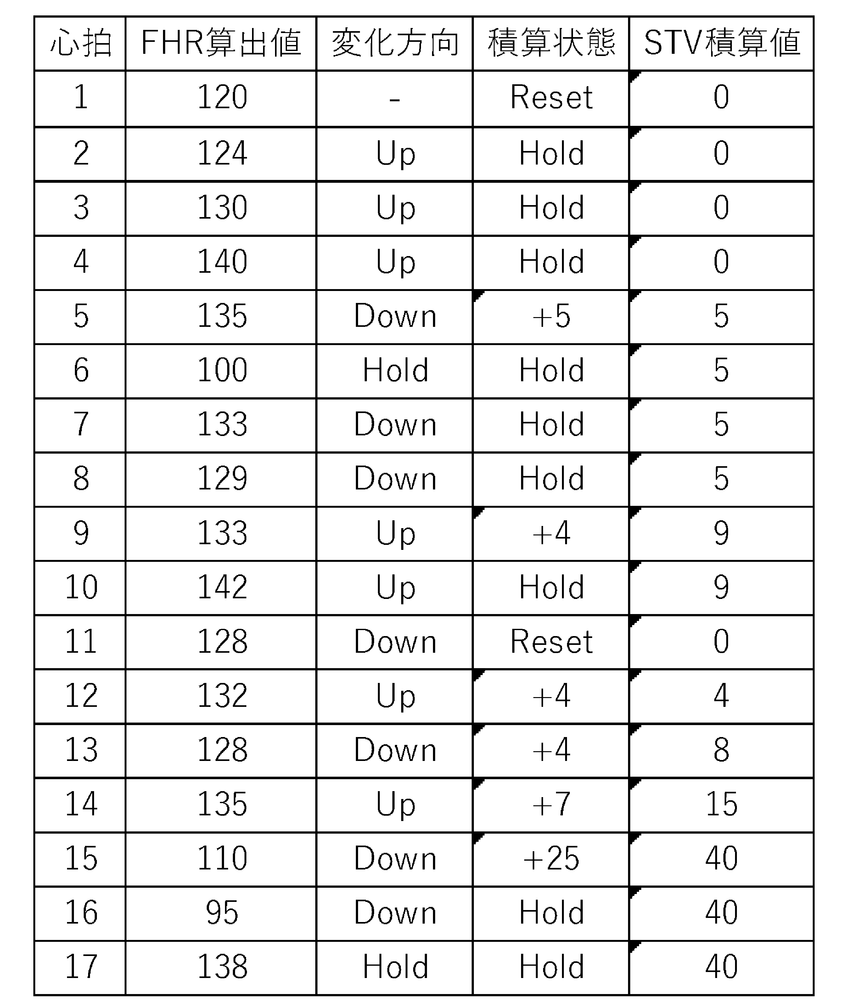

表1は、STV(STV積算値)の算出方法を示す表である。LTV及びSTV変換処理部35は、現在のFHR算出値が、その前に取得されたFHR算出値と同じ方向へ変化した場合(例えば、表1の心拍2及び3に示すように、「その前に取得されたFHR算出値」に相当する心拍2の変化方向が上昇を意味する「Up」であるところ、「現在のFHR算出値」に相当する心拍3のFHR算出値が124から130に上昇した場合)には、STV積算値に上記差の絶対値(+6)を加算しない。一方、現在のFHR算出値がその前に取得されたFHR算出値と異なる方向へ変化した場合(例えば、表1の心拍4及び5に示すように、「その前に取得されたFHR算出値」に相当する心拍4の変化方向が上昇を意味する「Up」であるところ、「現在のFHR算出値」に相当する心拍5のFHR算出値が140から135に下降した場合)には、STV積算値に上記差の絶対値(+5)を加算する。また、現在のFHR算出値とその前に取得されたFHR算出値との差が所定量(例えば、±26bpm)以上の場合(例えば、表1の心拍5及び6に示すように、「その前に取得されたFHR算出値」に相当する心拍5のFHR算出値が135であり、「現在のFHR算出値」に相当する心拍6のFHR算出値が100であり、その差が-35である場合)には、STV積算値に上記差の絶対値を加算せず、かつ、前回のFHR算出値を更新しない。より具体的に説明すると、表1に示す心拍7のSTV積算値を算出するにあたり、心拍6のFHR算出値(100)ではなく心拍5のFHR算出値(135)をベースにして、心拍7のFHR算出値(133)と対比する。この場合、心拍5の変化方向が下降を意味する「Down」であるところ、心拍7のFHR算出値が135から133に下降していることから、STV積算値に上記差の絶対値(+2)を加算しない。
表2は、LTV(LTV積算値)の算出方法を示す表である。LTV及びSTV変換処理部35は、現在のFHR算出値が、その前に取得されたFHR算出値と同じ方向へ変化した場合(例えば、表2の心拍2及び3に示すように、「その前に取得されたFHR算出値」に相当する心拍2の変化方向が上昇を意味する「Up」であるところ、「現在のFHR算出値」に相当する心拍3のFHR算出値が124から130に上昇した場合)には、LTV積算値に上記差の絶対値(+6)を加算する。一方、現在のFHR算出値がその前に取得されたFHR算出値と異なる方向へ変化した場合(例えば、表2の心拍4及び5に示すように、「その前に取得されたFHR算出値」に相当する心拍4の変化方向が上昇を意味する「Up」であるところ、「現在のFHR算出値」に相当する心拍5のFHR算出値が140から135に下降した場合)には、LTV積算値に上記差の絶対値(+5)を加算しない。また、現在のFHR算出値とその前に取得されたFHR算出値との差が所定量(例えば、±26bpm)以上の場合(例えば、表2の心拍5及び6に示すように、「その前に取得されたFHR算出値」に相当する心拍5のFHR算出値が135であり、「現在のFHR算出値」に相当する心拍6のFHR算出値が100であり、その差が-35である場合)には、LTV積算値に上記差の絶対値を加算せず、かつ、前回のFHR算出値を更新しない。より具体的に説明すると、表2に示す心拍7のLTV積算値を算出するにあたり、心拍6のFHR算出値(100)ではなく心拍5のFHR算出値(135)をベースにして、心拍7のFHR算出値(133)と対比する。この場合、心拍5の変化方向が下降を意味する「Down」であるところ、心拍7のFHR算出値が135から133に下降していることから、LTV積算値に上記差の絶対値(+2)を加算する。
本実施形態のSTV及びLTVの算出期間は、10心拍ごとであるため、表1及び2の心拍1及び11に示すように、10心拍ごとにSTV積算値及びLTV積算値をリセット(Reset)することとしている。
なお、STV及びLTVの算出期間は、心拍回数を基準とせず、例えば、所定時間ごと(例えば、1分ごと)に算出することとしてもよい。この場合、STV積算値及びLTV積算値は所定時間ごとにリセットされることとなるため、所定時間ごと(例えば、1分ごと)のSTV及びLTVが算出されることとなる。
なお、STV及びLTVの算出期間は、心拍回数を基準とせず、例えば、所定時間ごと(例えば、1分ごと)に算出することとしてもよい。この場合、STV積算値及びLTV積算値は所定時間ごとにリセットされることとなるため、所定時間ごと(例えば、1分ごと)のSTV及びLTVが算出されることとなる。
このような方法によって算出された算出期間(本実施形態では10心拍ごと、又は1分ごと)のSTV及びLTVが、記憶部36に記憶される。
なお、本実施形態では、STV及びLTVは、上記方法により算出されることとしたが、これに限らず、例えば、「医用電子と生体工学」第23巻第1号(昭和60年2月)の「胎児心拍に関する各種variability indexの同一性について」の22頁の第1表に示された定義式から算出することとしてもよい。
分娩監視装置(図示省略)から情報取得部52に入力された信号のうち、陣痛トランスデューサによって検出された圧力変化に関する信号は、図2に示す処理部11のブロック図に示すように、数値化処理部37において、信号増幅、AD変換又は記録・保存処理のためのデータ区分分け等の信号処理が行われる。数値化処理部37で処理された信号は、数値化処理部37から演算処理部38に受け渡され、演算処理部38において0~100に対応する陣痛強度が算出される。そして、算出された陣痛強度は、記憶部36に記録される。
分娩監視装置(図示省略)から情報取得部52に入力された信号のうち、超音波トランスデューサによって検出された胎児の心拍動に関する信号も同様に、数値化処理部37において、信号増幅、AD変換又は記録・保存処理のためのデータ区分分け等の信号処理が行われた後、演算処理部38において胎児心拍数が算出され、記憶部36に胎児心拍数が記憶される。
なお、情報取得部52を介して得られる胎児心拍数は、検出部51を介して得られる胎児心拍数(胎児心拍数変換処理部34によって算出された胎児心拍数)とは別のものである。
なお、情報取得部52を介して得られる胎児心拍数は、検出部51を介して得られる胎児心拍数(胎児心拍数変換処理部34によって算出された胎児心拍数)とは別のものである。
本実施形態では、分娩監視装置から情報取得部52に入力された信号が、数値化処理部37において信号処理され、演算処理部38において陣痛強度及び胎児心拍数が算出されることとしたが、これに限らず、例えば、数値化処理部37及び演算処理部38と同様の機能を有する処理部を分娩監視装置等の外部機器が備えており、当該外部機器内で演算して求めた陣痛強度及び胎児心拍数に関する情報が、監視装置101の情報取得部52に入力されることとしてもよい。この場合、監視装置101の処理部11は、数値化処理部37及び演算処理部38を備えていなくてもよい。
記憶部36に記録された胎児生体電気信号、胎児心拍数、母体心電図信号、母体心拍数、STV及びLTV並びに陣痛強度は、表示処理部39に送られる。表示処理部39では、これらの情報に基づく描画処理がなされて、母体心電図信号に基づく母体心電図(母体心電図波形)、胎児生体電気信号に基づく胎児生体電気信号図(胎児生体電気信号波形)、胎児心拍数に基づく胎児心拍数図並びにSTV及びLTVに基づく心拍変動図に関する情報が作成される。これらの情報が、図1及び図3に示すように、母体心電図21、胎児生体電気信号図22、胎児心拍数図23及び心拍変動図24として、表示部12に表示される。なお、心拍変動図24は、陣痛強度に基づく陣痛強度図内に表示され、陣痛強度曲線(図3では省略)に重ねて表示される。
このように、本実施形態の監視装置101では、処理部11の表示処理部39と、表示部12とにより、母体心電図21、胎児生体電気信号図22、胎児心拍数図23及び心拍変動図24の情報とともに、ユーザが指定した任意期間におけるSTV及びLTVの情報も別途表示され、これらの表示処理部39及び表示部12により、本発明の表示手段及び報知手段が構成される。
なお、本実施形態では、任意期間の長さは、予め1分間に設定されているが、その設定された長さ(時間)は、ユーザが任意に変更可能である。
なお、本実施形態で用いた検出部51や処理部11における処理方法は一例であり、本実施形態において、母体心電図信号、胎児生体電気信号及び胎児心拍数のそれぞれの計測・演算手法は、特に限定されるものではない。また、本実施形態では、検出部51はいずれも外測法による検出手段とされるが、内測法による検出手段を使用することも可能であるし、外側法による検出手段のうち本実施形態とは異なる検出手段を使用することも可能である。分娩監視装置についても同様に、内測法及び外側法の区別を問わず、種々の検出手段を用いることができる。
また、本実施形態の監視装置101では、検出部51により検出された信号を用いて母体心電図信号、胎児生体電気信号等の情報を取得するとともに、得られた母体心電図信号及び胎児生体電気信号から母体心拍数及び胎児心拍数を取得していたが、母体心拍数や胎児心拍数の取得方法はこれに限られるものではない。例えば、上記検出部51に代えて、母体及び胎児に電極等を直接装着することにより母体心拍数及び胎児心拍数を直接的に取得可能な検出手段を用いることも可能である。
次に、表示部12の表示内容について、より具体的に説明する。表示部12は、図3に示すように、母体及び胎児の情報を表示する表示機能とともに入力機能(操作機能)を兼ね備えるタッチパネル式のディスプレイ(モニタ)である。表示部12の画面上には、母体心電図21、胎児生体電気信号図22、胎児心拍数図23及び心拍変動図24が表示される。母体心電図21には母体心電図信号の波形が表示され、胎児生体電気信号図22には胎児生体電気信号の波形が表示され、胎児心拍数図23には胎児心拍数を経時的に示す胎児心拍数曲線TSが表示され、心拍変動図24にはSTV及びLTVが表示される。胎児心拍数図23には、胎児心拍数曲線TSの他、母体心拍数曲線BS及び外部入力された胎児心拍数を経時的に示す胎児心拍数曲線USが同時に表示される。これら母体心電図21、胎児生体電気信号図22、胎児心拍数図23及び心拍変動図24において、横軸は時間軸であり、縦軸は各指標の数値軸である。
なお、母体心電図21及び胎児生体電気信号図22における横軸の表示幅(時間範囲)は、胎児心拍数図23における横軸の表示幅(時間範囲)に比べて短く、胎児心拍数図23の10分の1~1000分の1程度(好ましくは20分の1~100分の1)であり、したがって表示倍率が10倍~1000倍(好ましくは20倍~100倍)ほどとなっている。例えば、胎児心拍数図23の表示幅が十数分間に設定される一方、母体心電図21及び胎児生体電気信号図22の表示幅は十数秒間に設定される。これにより、母体心電図21及び胎児生体電気信号図22では、母体心電図波形及び胎児生体電気信号波形をより詳細に表示することができる。
なお、胎児心拍数図23及び心拍変動図24の情報は、図3の右端(横軸の右端)が最新の情報とされる。また、表示部12の表示画面には、収録時間を表示する収録時間表示領域26が設けられており、最新の時間(胎児心拍数図23における図3の右端の時間)が表示されるようになっている。
また、表示部12の表示画面のうち胎児生体電気信号図22の右側には、検出部51によって検出された胎児生体電気信号を基に算出された胎児心拍数(胎児心拍数変換処理部34によって算出された胎児心拍数)をデジタル表示する胎児心拍数デジタル表示領域22dが設けられており、表示部12の一つの画面上で、胎児生体電気信号の波形とともに、デジタル表示された胎児心拍数を同時に確認できるようになっている。同様に、表示部12の表示画面のうち母体心電図21の右側には、母体心拍数をデジタル表示する母体心拍数デジタル表示領域21dが設けられており、表示部12の一つの画面上で、母体心電図信号の波形とともに、デジタル表示された母体心拍数を同時に確認できるようになっている。さらに、表示部12の表示画面のうち胎児心拍数図23の右側には、上記胎児心拍数デジタル表示領域22dとは別に、情報取得部52に入力された信号を基に算出された胎児心拍数(数値化処理部37及び演算処理部38によって算出された胎児心拍数)をデジタル表示する胎児心拍数デジタル表示領域23dが設けられており、胎児生体電気信号から算出された胎児心拍数及び外部入力された胎児心拍数を同時に確認できるようになっている。これにより、仮に2つの胎児心拍数のいずれか一方が一時的にデジタル表示されない等の不具合が発生したとしても、他方の胎児心拍数がデジタル表示されていれば、ユーザは継続して胎児心拍数を確認することができる。
なお、表示部12の表示画面には、図3に示す画面の他にも、複数の画面を切り替えて表示可能である。
次に、表示部12の入力機能(操作機能)について具体的に説明する。表示部12は、図1に示すように、イベント入力部41及び期間指定部42を有する操作部14を備えている。ユーザが表示部12の画面上に表示された操作スイッチを操作する(例えば、押す、触れる)ことにより、各種の操作が行えるように構成されている。
イベント入力部41は、例えば、図3に示す表示部12の右下部分に配置された6つのアイコンからなるイベント記録ボタン41a~41fと、イベント記録ボタン41a~41fの下に配置されたウインドウ41hとを備える。イベント入力部41は、母体の体位変換や母体内で睡眠中の胎児を起こすための振動を与えたこと等の、各種イベント情報に関して、ユーザからの入力操作を受け付けるとともに、ユーザから入力を受け付けたときに当該入力に関する情報を表示処理部39に送る機能を有する。表示処理部39に送られた当該情報は、表示処理部39において描画処理されて再度表示部12に送られるか、記憶部36に格納される(記録される)。ウインドウ41hには、ユーザが入力操作したイベント記録ボタンの種類と、当該イベント記録ボタンが入力操作された時間とが、紐付けられて表示されている。これらイベント記録ボタンの種類と操作時間とは、ウインドウ41hの上部から下部へと順次時系列的に表示される。
イベント記録ボタン41a~41fについて具体的に説明すると、例えば、図3に示すイベント記録ボタン41aは母体の体位変換を表すアイコンであり、イベント記録ボタン41bは母体内で睡眠中の胎児を起こすための振動を与える信号の送信を表すアイコンであり、イベント記録ボタン41cはSTV及びLTVを算出する任意期間の始点に配置するためのマーカーを表すアイコンであり、イベント記録ボタン41dは母体への酸素供給を表すアイコンであり、イベント記録ボタン41eは母体への輸血を表すアイコンであり、イベント記録ボタン41fは検出部51の故障を表すアイコンである。ユーザは、イベント発生時に、対象となるイベント記録ボタン41a~41fを指やタッチペン等で押下したまま胎児心拍数図23の上側に移動(ドラッグ)し、所望の位置で指やタッチペン等を離す(ドロップする)と、表示処理部39において描画処理され、胎児心拍数図23の上側にイベント情報(例えば、図3に示す簡易イベント記録ボタン61c)が表示される。
例えば、ユーザが胎児心拍数図23の上側にイベント記録ボタン41cをドラッグ&ドロップすると、胎児心拍数図23の上側に簡易イベント記録ボタン61cが表示される。また、簡易イベント記録ボタン61cが配置された位置(時刻)を始点として、LTV及びSTV変換処理部35が上記始点から任意期間(例えば、1分間)のLTV及びSTVが算出されて、当該任意の期間における胎児心拍数の平均値とともにLTV及びSTVが表示される。ドラッグ&ドロップ操作(移動操作)の検知は、イベント入力部41により実行される。イベント入力部41は、イベント記録ボタン41cが表示されている位置(第1の位置)から、胎児心拍数図23上の位置(第2の位置)までの移動操作を検知したとき、当該移動操作の終了位置(すなわち第2の位置)を始点として、任意期間を指定する機能を有する。すなわち、イベント入力部41は、本発明の指定期間入力部に相当する。
また、本実施形態では、任意期間を示す情報として、胎児心拍数図23の時間軸に沿って横方向に延びるバー61c1が表示されるように構成されている。このバー61c1は、ユーザが指定した任意期間の長さに応じた長さで表示される。ユーザは、このバー61c1の始点及び終点の位置を確認することにより、胎児心拍数図23上における任意期間を明確に認識できる。また、このバー61c1が示す任意期間における胎児心拍数の平均値、STV及びLTVがバー61c1の下方に表示される。
なお、本実施形態では、表示部12がタッチパネル式のディスプレイであり、ドラッグ&ドロップ操作する場合を例示して説明したが、これに限定されない。例えば、表示部が画面上にポインタを表示するタイプのディスプレイである場合には、対象となるイベント記録ボタンをポインタで選択し、胎児心拍数図上の所望の位置をポインタで選択することにより、胎児心拍数図の上側にイベント情報(簡易イベント記録ボタン)を表示させることができる。また、表示部がタッチパネル式のディスプレイであっても、ポインタ表示機能を備えているのであれば、例えば、対象となるイベント記録ボタンを指やタッチペンで押下した後、胎児心拍数図上の所望の位置を指やタッチペンで押下することにより、胎児心拍数図の上側にイベント情報(簡易イベント記録ボタン)を表示させることができる。
また、図3に示す表示部12の最下部には、各種選択ボタン81~88が配置されている。ユーザによってこれら選択ボタン81~88のいずれかが選択されることにより、表示部12に表示される画面が変更される。例えば、選択ボタン81は、TOP画面を表示させるためのボタンであり、選択ボタン82は、再生を終了させるためのボタンである。選択ボタン83は、マーカーボタンであり、選択ボタン83を選択することにより胎児心拍数図23等にマーカーを配置することができるボタンである。また、選択ボタン84は、キャプチャボタンであり、選択ボタン84を選択した時点での表示部12に表示された画面をキャプチャ画像にする、いわゆるスクリーンショットボタンである。本実施形態では、選択ボタン84を選択したタイミングで、胎児心拍数図23上にキャプチャを示す簡易イベントボタン64が表示される。選択ボタン85は、波形の表示高を切り替えるためのボタンであり、選択ボタン86は、選択ボタン88により画面が切り替えられた後に使用されるボタンである。また、選択ボタン87は、解析した波形を表示させるための解析波形ボタンであり、選択ボタン88は、画面を切り替えるための切り替えボタンである。
なお、図示を省略するが、上記イベント情報の他にも、分離・解析処理部32において解析エラー等が発生した場合に、解析エラーの発生等を示すイベント情報が自動的に表示部12の胎児心拍数図23に表示されるようになっている。分離・解析処理部32において解析エラー等が発生すると、当該情報が記憶部36に格納される(記録される)とともに表示処理部39に送られ、表示処理部39において描画処理された後、表示部12の胎児心拍数図23に表示される。
心拍変動図24には、予め設定された時間間隔(例えば、1分間隔)で算出されたSTV及びLTVが、STV及びLTVが算出されるごとに表示される。本実施形態では、STV及びLTVがそれぞれ異なる色(例えば、青色及び赤色)により折れ線グラフ形式で表示される。
なお、この時間間隔は、予め記憶部36に記憶されていてもよいし、ユーザが自ら設定可能であってもよい。
なお、この時間間隔は、予め記憶部36に記憶されていてもよいし、ユーザが自ら設定可能であってもよい。
また、表示部12には、リアルタイムに処理された各種情報に基づいて母体心電図21、胎児生体電気信号図22、胎児心拍数図23及び心拍変動図24のそれぞれが表示できるだけでなく、既に記憶部36に蓄積された記録済みの情報を呼び出して、その蓄積された各種情報に基づいて母体心電図21、胎児生体電気信号図22、胎児心拍数図23及び心拍変動図24を表示させることもできる。
例えば、図3に示す表示部12の胎児心拍数図23の下部には、収録開始時点からの情報蓄積時間を表すスクロールバー71が設けられており、表示部12の胎児心拍数図23には、スクロールバー71上のスクロール枠72で囲まれた期間内の情報が表示されるようになっている。このように、胎児心拍数図23には、画面上に表示可能な期間を超えて情報が蓄積された場合に、記憶部36に蓄積された情報の一部が表示されるようになっている。また、記憶部36に蓄積された情報のうち、画面上の胎児心拍数図23に表示されていない期間の情報は、スクロールバー71に沿って画面の左右方向にスクロール枠72を移動させることにより、当該期間の情報を胎児心拍数図23に表示できる。
なお、スクロール枠72は、表示部12の画面を指でなぞることによりスクロールバー71上の任意の位置に移動させることができるが、その他にもスクロールバー71の左右に配置された期間戻りボタン73a及び期間送りボタン73bを操作する(押す、触れる)ことにより、現時点の表示期間に隣接する期間上にスクロール枠72を移動させ、その期間における胎児心拍数やLTV及びSTVの情報を胎児心拍数図23や心拍変動図24に表示させることができる。例えば、期間送りボタン73bを操作した場合は、スクロール枠72が右側に移動し、現時点の表示期間の右側に隣接する期間(現時点よりも後の期間であって、現時点よりも新しい情報)の胎児心拍数やLTV及びSTVの情報が胎児心拍数図23及び心拍変動図24に表示される。
一方、期間戻りボタン73aを操作した場合には、スクロール枠72が左側に移動し、現時点の表示期間の左側に隣接する期間(現時点よりも前の期間であって、現時点よりも古い情報)の胎児心拍数やLTV及びSTVの情報が胎児心拍数図23及び心拍変動図24に表示される。また、続けて期間戻りボタン73aを操作することで、スクロール枠72をさらに左側に移動させ、その位置における胎児心拍数やLTV及びSTVの情報を胎児心拍数図23及び心拍変動図24に表示させることができる。このように、期間戻りボタン73a及び期間送りボタン73bを使用した場合には、スクロール枠72で囲まれた期間ごとの胎児心拍数やLTV及びSTVの情報を胎児心拍数図23及び心拍変動図24に順に表示させることができる。
また、図3に示すように、再生中の胎児心拍数図23上には、この胎児心拍数図23に表示された表示時間軸内のさらに短期間の位置(指定期間)を指定可能な期間指定部42が設けられている。このときの短期間は、例えば数秒間である。期間指定部42を画面の左右方向に移動させて胎児心拍数図23の表示時間軸内の任意の位置に配置することで、その期間指定部42が重なって配置された期間における胎児生体電気信号(波形)を胎児生体電気信号図22に表示できるとともに、その期間における母体心電図信号(波形)を母体心電図21に表示できる。母体心電図21及び胎児生体電気信号図22には、期間指定部42により指定された指定期間が領域42a,領域42bによりそれぞれ示されている。
胎児生体電気信号図22内の領域42bには、期間指定部42により指定された指定期間内の胎児生体電気信号波形が表示されている。この領域42bの前後(左右)の期間、つまり指定期間に隣接する前後の期間も含めて、胎児生体電気信号波形が連続して表示されており、領域42bと領域42b以外の領域とで背景色を変更している。これにより、指定期間における胎児生体電気信号と他の期間における胎児生体電気信号との違いをユーザが明確に判別可能となる。
胎児生体電気信号図22と同様に、母体心電図21内にも領域42aが表示されており、領域42aと領域42a以外の領域とで背景色を変更していることから、指定期間における母体心電図信号と他の期間における母体心電図信号との違いをユーザが明確に判別可能となる。母体心電図21と胎児生体電気信号図22とは、常に同じ時間範囲の情報を表示している。
期間指定部42は、画面の1ピクセル~数ピクセルの幅で表示される縦線を有するマーカーであり、この幅に相当する時間が指定期間として指定され、母体心電図21及び胎児生体電気信号図22において領域42a,42bによって示される。例えば期間指定部42の幅が1秒間に相当する場合、指定期間として例えば1秒間が指定される。母体心電図21及び胎児生体電気信号図22においては、画面上、時間軸の表示設定が例えば胎児心拍数図23の100分の1である場合は、期間指定部42の幅の100倍の幅が領域42a,42bによって囲まれる。
図3では、スクロールバー71は測定時間全て(例えば数時間分)の情報を示しており、胎児心拍数図23はスクロール枠72に囲まれた時間(例えば15分間)の情報を示している。これに対し、母体心電図21及び胎児生体電気信号図22は、胎児心拍数図23よりも短い時間(例えば10秒間)の情報を拡大して示しており、期間指定部42により指定された指定期間(例えば1秒間)が領域42a,42bにより示されている。
なお、期間指定部42により指定された指定期間内の胎児生体電気信号と、この指定期間に隣接する他の期間における胎児生体電気信号と、を識別可能に表示する手段としては、領域42a,42bの背景色を他の期間と異なる色に変更することとしたが、胎児生体電気信号図22の一部を囲む枠線により表示する他、指定期間内の胎児生体電気信号の波形を示す線の色を他の期間と異なる色に変更したり、胎児生体電気信号の波形の太さを変更したりする等の種々の手段を採用することができる。
このように、本実施形態の監視装置101では、期間指定部42により指定期間が指定されたときに、その指定期間における胎児生体電気信号と母体心電図信号とを表示部12に表示でき、ユーザが容易に確認できるようになっている。
また、スクロールバー71には、胎児心拍数図23上に表示される簡易イベント記録ボタン61c等に対応する簡易アイコン等が表示されるようになっており、ユーザはイベント情報の有無をスクロールバー71において容易に確認できる。このため、ユーザはイベント情報と胎児心拍数図23の情報との相関を容易に認識できる。
また、スクロールバー71の左右には、イベント表示戻りボタン75a及びイベント表示送りボタン75bが配設されており、このイベント表示戻りボタン75a及びイベント表示送りボタン75bを操作する(押す、触れる)ことにより、現時点のスクロール枠72が配置された位置から最も近い位置のイベント情報が記録された期間まで、スクロール枠72を移動させることができる。そして、この期間における胎児心拍数及び陣痛強度の情報を胎児心拍数図23に瞬時に表示できるようになっている。
なお、イベント表示送りボタン75bを操作した場合には、現時点のスクロール枠72から画面右側の範囲において最も近い位置に配置されたイベント情報を表示期間の中心として、胎児心拍数図23が表示される。続けてイベント表示送りボタン75bを操作すると、現時点の表示期間の中心位置に配置されたイベント情報から、さらに画面右側のイベント情報を表示期間の中心として、胎児心拍数図23が表示される。イベント表示戻りボタン75aを操作した場合も同様に、現時点のスクロール枠72から画面左側の範囲において最も近い位置に配置されたイベント情報を表示期間の中心として、胎児心拍数図23が表示される。このように、監視装置101においては、イベント表示戻りボタン75a及びイベント表示送りボタン75bを操作することで、容易にイベント情報にアクセス可能となっている。
前述の操作部14には、イベント入力部41及び期間指定部42の他、表示部12上で操作可能なイベント表示戻りボタン75a及びイベント表示送りボタン75b等も含まれる。
なお、本実施形態では、表示機能と入力機能(操作機能)を兼ね備えるタッチパネル式のディスプレイにより表示部12を構成したが、これに限定されず、例えば、表示部12の傍に独立した個別の操作部を配設してもよい。この場合、ユーザは表示部12を確認しながら容易に操作を行うことができる。
[胎児の心拍変動監視装置の動作]
次に、監視装置101の動作について説明する。監視装置101の運転(計測)が開始されると、検出部51から取得された信号及び情報取得部52から入力された信号が処理部11で処理され、表示部12には、図3に示すように胎児心拍数図23及び心拍変動図24が表示される。表示部12には、前述したように、胎児心拍数図23、心拍変動図24とともに、胎児生体電気信号の波形を表示する胎児生体電気信号図22と、母体心電図信号の波形を表示する母体心電図21と、が同時に表示される。
次に、監視装置101の動作について説明する。監視装置101の運転(計測)が開始されると、検出部51から取得された信号及び情報取得部52から入力された信号が処理部11で処理され、表示部12には、図3に示すように胎児心拍数図23及び心拍変動図24が表示される。表示部12には、前述したように、胎児心拍数図23、心拍変動図24とともに、胎児生体電気信号の波形を表示する胎児生体電気信号図22と、母体心電図信号の波形を表示する母体心電図21と、が同時に表示される。
通常の母体心電図信号、胎児生体電気信号、胎児心拍数及び母体心拍数の計測中においては、表示部12にはリアルタイムに処理された情報が表示される。これらの情報は時間軸とともに表示され、時間の経過に伴い逐次更新される。
前述したように、胎児心拍数図23及び心拍変動図24の情報は、図3の右端が最新の情報とされる。また、収録時間表示領域26には、最新の情報である測定時の時刻が表示され、時間の経過とともに情報更新される。母体心電図21及び胎児生体電気信号図22の情報は、例えば、単位時間ごとに図3の左端側から右端側に順に更新されていき、更新箇所が右端に到達すると、左端に戻り更新される。胎児心拍数図23の右端の時間に対応する母体心拍数及び胎児心拍数が、母体心拍数デジタル表示領域21d及び胎児心拍数デジタル表示領域22dに数値として表示される。
なお、母体心電図21及び胎児生体電気信号図22の情報の更新は、これに限らず、時間の経過とともに画面がスクロールされるものであってもよい。
監視中、ユーザがイベント入力部41を操作した場合には、その操作されたイベント記録ボタン41a~41fに対応するイベント情報のイベントアイコンが、胎児心拍数図23上に表示される。これらのイベント情報は、発生時刻とともに記憶部36に格納(記憶)される。
これまで述べたように、本実施形態の監視装置101では、胎児心拍数図23における変動情報を認識したい任意期間をユーザが指定することで、任意期間における変動情報として平均心拍数、STV及びLTVが報知されるので、任意期間における胎児の状況判断を容易にできる。
また、予め設定された時間間隔でSTV及びLTVが算出され、算出されるごとにSTV及びLTVが心拍変動図24としてグラフ表示されることから、STV及びLTVの経時的な変化を認識でき、胎児の状況判断をより容易にできる。
また、ユーザは、STV及びLTVの少なくとも一方の経時的変化を認識した上で、任意期間を指定できるので、胎児の状況判断をより容易にできる。具体的には、予め設定された時間間隔で算出されて表示されたSTVやLTVの値に疑問を感じた場合に、ユーザは、疑問を感じた領域(例えば、胎児心拍数にノイズが生じている領域)を除外した任意期間を設定することで、適切なSTV及びLTVを取得でき、胎児の状況判断をより容易に行うことができる。
なお、本発明は上記実施形態に限定されるものではなく、本発明の趣旨を逸脱しない範囲において種々の変更を加えることが可能である。
例えば、上記実施形態では、所定時間ごとに算出されたLTV及びSTVを心拍変動図24に表示することとしたが、これに限らない。
図4は、上記実施形態の第1変形例に係る監視装置101の表示部12の正面図である(この第1変形例において、上記実施形態と共通要素には同一符号を付して説明を省略する。以下の各変形例においても同様とする。)。第1変形例では、図4に示すように、所定時間ごとに算出されたLTVのみを心拍変動図24に表示している。この場合、LTV及びSTV変換処理部35は、所定時間ごとのLTVのみを算出すればよいが、STVも合わせて算出してもよい。
図5は、上記実施形態の第2変形例に係る監視装置101の表示部12の正面図である。第2変形例では、図5に示すように、所定時間ごとに算出されたSTVのみを心拍変動図24に表示している。この場合、LTV及びSTV変換処理部35は、所定時間ごとのSTVのみを算出すればよいが、LTVも合わせて算出してもよい。
また、上記実施形態では、心拍変動図24におけるSTV及びLTVを折れ線グラフ形式で表示することとしたが、これに限らない。
図6は、上記実施形態の第3変形例に係る監視装置101の表示部12の正面図である。第3変形例では、図6に示すように、心拍変動図24にSTV及びLTVを縦棒グラフ形式で表示している。また、第3変形例では、心拍変動図24における所定時間ごとに算出されたSTV又はLTVと、ユーザが指定した任意期間とが重なっている場合、任意期間におけるSTV及びLTVがその他の期間におけるSTV及びLTVよりも目立つ色で表示される。例えば、所定時間ごとに算出されたSTV及びLTVは、それぞれ薄橙色及び薄青色で表示され、任意期間におけるSTV及びLTVは、濃橙色及び濃紺色で表示される(図6の符号61c3)。このため、ユーザは、任意期間を示すバー61c1の下方に表示されたSTV及びLTVの数値とともに、心拍変動図24上でも任意期間におけるSTV及びLTVを容易に認識できる。
なお、心拍変動図24における所定時間ごとに算出されたSTV又はLTVと、ユーザが指定した任意期間とが重なっていない場合であっても、任意期間のSTV又はLTVがその他の期間におけるSTV又はLTVとは異なる色で表示されてもよい。
また、胎児心拍数図において任意期間を示す情報は、バー61c1に限らない。例えば、胎児心拍数図23上で任意期間を区画して表示してもよいし、任意期間における胎児心拍数曲線の色又は胎児心拍数図の背景色を任意期間以外のものとは異なる色で表示してもよい。また、任意期間の始点と終点のみにマーカー等を表示してもよい。
また、上記実施形態では、表示部12に陣痛強度を表示していなかったが、表示部12に陣痛強度を表示することとしてよい。
図7は、上記実施形態の第4変形例に係る監視装置101の表示部12の正面図である。第4変形例では、上記第3変形例と同様に、心拍変動図24にSTV及びLTVを縦棒グラフ形式で表示するとともに、陣痛強度曲線JKを合わせて表示している(図7参照)。このため、胎児心拍数、母体心拍数、母体心電図信号、胎児生体電気信号並びにSTV及びLTVとともに、母体の陣痛強度も合わせて取得でき、ユーザは胎児の状況判断をさらに詳細に認識できる。
また、上記実施形態において、表示部12の右下部分に表示されたウインドウ41hのサイズは、変更可能であってもよい。
図8は、上記実施形態の第5変形例に係る監視装置101の表示部12の正面図である。第5変形例では、図8に示すように、ウインドウ41hのサイズを拡大することができる。例えば、ユーザがウインドウ41hを拡大する操作(例えば、ウインドウ41hの範囲内を親指及び人差し指でタッチした状態で、これらの間隔を広げる動作。いわゆるピンチアウト)を実行すると、ウインドウ41hがその表示範囲を拡大して表示される。これにより、ユーザは、各種イベント情報とイベント情報が入力された時間とをより容易に認識可能となる。
上記実施形態では、胎児の心拍変動に関する情報(変動情報)として、任意期間内における胎児の平均心拍数、STV及びLTVが報知されることとしたが、これに限らない。
図9は、上記実施形態の第6変形例に係る監視装置101の表示部12の正面図である。第6変形例では、胎児の心拍変動に関する情報(変動情報)として、任意期間内における胎児の平均心拍数、最大心拍数、最小心拍数及び最大心拍数と最小心拍数との差が報知される。具体的には、図9に示すように、胎児心拍数図23の任意期間における胎児心拍数曲線を囲う枠91,92,93を表示する。
枠91,92,93の幅は、任意期間の長さに応じて設定される。つまり、各枠91,92,93の左端の位置が任意期間の始点に対応し、各枠91,92,93の右端の位置が任意期間の終点に対応する。また、各枠91,92,93の高さは、任意期間における胎児心拍数曲線内の胎児心拍数の最小値から最大値までの高さ(最大心拍数と最小心拍数との差)に応じて設定される。図9では、各枠91,92,93の高さは、任意期間における胎児心拍数の最小値から最大値までの高さとして設定されている。例えば、図9に示す3つの簡易イベント記録ボタン61jが配置された任意期間について、最大心拍数と最小心拍数との差は、画面左側から順に「4」、「10」、「94」である。このため、枠91の高さが最も小さく、枠93の高さが最も大きくなる。このように、任意期間における胎児心拍数の最大値と最小値との差が大きい程、上記枠の高さが大きくなることから、ユーザは胎児心拍数図23内に表示された枠の大きさを視認するだけで胎児の心拍変動が大きいことを認識でき、胎児の状況判断をより適切にできる。また、枠91,92,93の幅が任意期間の長さに対応しているため、ユーザは胎児心拍数変動の大小とともに任意期間の長さも容易に認識することができる。
なお、ユーザが胎児心拍数変動の大小と任意期間の長さの違いを認識できるものであれば、上記枠に限られず、例えば、他の領域と異なる色や網掛けパターン等で塗りつぶされた四角形で表示してもよい。
なお、図9に示すように、図面右側に示す枠93の高さは、胎児心拍数基線の高さよりも小さく設定されている。これは、分離・解析処理部32によりノイズと判定された胎児心拍数を含めることなく枠93が設定されるためである。この分離・解析処理部32によるノイズ判定は、定法により行われる。これにより、ユーザは、ノイズ除去された胎児心拍数のみで枠91,92,93の高さ、すなわち胎児心拍数の変動が算出されていることを目視にて確認できる。
また、上記第6変形例では、変動情報の値に応じて、バー61j1を異なる態様で表示されるように構成されている。具体的には、図9に示す3つのバー61j1について、図面左側から順に黄緑色、青色、赤色で表示されている。各バー61j1の色は、各バー61j1が位置する任意期間の、胎児の最大心拍数と最小心拍数との差の大小に対応している。このように、変動情報(胎児の最大心拍数と最小心拍数の差)の値に応じてバー61j1が異なる色(態様)で表示されるので、ユーザは、バー61j1の表示態様に応じて変動情報の値の緊急度を認識でき、確実に胎児の状況判断が可能となる。
なお、上記実施形態及び各変形例では、イベント記録ボタンが胎児心拍数図23の表示領域よりも外側(表示部12の画面右側端)に配置されていることとしたが、これに限らず、例えば、ユーザが胎児心拍数図23上の所望の位置を選択した際に各イベント記録ボタン41a~41fがポップアップ表示され、その中からイベント記録ボタン41cを選択したときに任意期間が設定されるようにしてもよい。この場合、ユーザによって胎児心拍数図23上の所望の位置が選択された後に、イベント記録ボタン41cが選択される。すなわち、本発明において、胎児心拍数図23上の所望の位置及びイベント記録ボタン41cの選択順は問わない。
また、上記各変形例に示した各種態様は、それぞれ組み合わせることも可能であり、枠91~93を第1~第5変形例において表示してもよい。また、変動情報の値に応じてバーの色を変更することも可能である。さらに、バーの色を変更することに加えて、バーの下方に表示される胎児心拍数等の数値の色を変更して表示してもよい。
上記実施形態では、胎児の心拍変動監視装置101は、分娩監視装置によって取得された信号が情報取得部52を介して入力される構成としたが、これに限らず、例えば、母体の腹部に取り付けられる陣痛トランスデューサ及び超音波トランスデューサに相当する検出手段を有していてもよい。この場合、胎児の心拍変動監視装置101は、分娩監視装置として用いることもできる。すなわち、表示部12の表示例は、分娩監視装置にも適用可能である。
本発明は、胎児の心拍変動を監視する胎児の心拍変動監視装置として利用できる。
10 装置本体
11 処理部
12 表示部
14 操作部
21 母体心電図
21d 母体心拍数デジタル表示領域
22 胎児生体電気信号図
22d 胎児心拍数デジタル表示領域
23 胎児心拍数図
24 心拍変動図
26 収録時間表示領域
31 取込処理部
32 分離・解析処理部
33 母体心拍数変換処理部
34 胎児心拍数変換処理部
35 LTV及びSTV変換処理部
36 記憶部
37 数値化処理部
38 演算処理部
39 表示処理部
41 イベント入力部(指定期間入力部)
41a~41f イベント記録ボタン
41h ウインドウ
42 期間指定部
42a,42b 領域
51 検出部
52 情報取得部
61c 簡易イベント記録ボタン
61c1,61j1 バー
71 スクロールバー
72 スクロール枠
73a 期間戻りボタン
73b 期間送りボタン
75a イベント表示戻りボタン
75b イベント表示送りボタン
81~88 選択ボタン
91,92,93 枠
101 胎児の心拍変動監視装置(監視装置)
TS,US 胎児心拍数曲線
BS 母体心拍数曲線
JK 陣痛強度曲線
Claims (10)
- 胎児心拍数を取得して、前記胎児心拍数を経時的に示す胎児心拍数図を表示する表示手段と、前記胎児心拍数から胎児の心拍変動に関する情報である変動情報を算出する算出手段と、前記胎児心拍数図上の任意期間を指定可能な指定期間入力部と、前記指定期間入力部により前記任意期間が指定されたときに、前記算出手段により算出された前記任意期間における前記変動情報を報知する報知手段と、を備えることを特徴とする胎児の心拍変動監視装置。
- 前記算出手段は、予め設定された時間間隔でSTV及びLTVの少なくとも一方の値を算出し、
前記表示手段は、逐次算出される前記値をグラフにより表示することを特徴とする請求項1に記載の胎児の心拍変動監視装置。 - 前記報知手段は、前記指定期間入力部により指定された前記任意期間を示す情報を、前記胎児心拍数図に対応させて前記表示手段により表示させることを特徴とする請求項1又は2に記載の胎児の心拍変動監視装置。
- 前記報知手段は、前記指定期間入力部により前記任意期間が指定されたときに、前記任意期間を示す情報とともに、前記任意期間における前記変動情報を前記胎児心拍数図の近傍に前記表示手段により表示させることを特徴とする請求項3に記載の胎児の心拍変動監視装置。
- 前記報知手段は、前記変動情報の値に応じて、前記変動情報及び前記任意期間を示す情報の少なくとも一方を異なる態様で表示させることを特徴とする請求項4に記載の胎児の心拍変動監視装置。
- 前記報知手段は、前記任意期間を示す情報を前記胎児心拍数図の時間軸に沿って前記任意期間に応じて延びるバーとして表示させることを特徴とする請求項3から5のいずれか一項に記載の胎児の心拍変動監視装置。
- 前記変動情報は、前記胎児心拍数の変動を示す情報を含み、
前記報知手段は、前記胎児心拍数図の前記任意期間における胎児心拍数曲線を包含する領域を表示し、
前記胎児心拍数図の縦軸方向における前記領域の大きさは、前記変動情報に応じて設定されることを特徴とする請求項1から6のいずれか一項に記載の胎児の心拍変動監視装置。 - 前記報知手段は、前記胎児心拍数図の前記任意期間における前記胎児心拍数曲線を囲う枠を表示し、
前記枠の高さは、前記任意期間における前記胎児心拍数曲線内の前記胎児心拍数の最小値から最大値までの高さに応じて設定されることを特徴とする請求項7に記載の胎児の心拍変動監視装置。 - 前記表示手段は、前記任意期間を設定するためのアイコンを表示し、
前記指定期間入力部は、前記アイコン及び前記胎児心拍数図上の任意の位置が選択されたとき、当該任意の位置を前記任意期間の始点として前記任意期間を指定することを特徴とする請求項1から8のいずれか一項に記載の胎児の心拍変動監視装置。 - 前記表示手段は、前記アイコンを前記胎児心拍数図よりも外側に表示し、
前記指定期間入力部は、前記アイコンの表示位置から、前記胎児心拍数図上の任意の位置までの移動操作を検知したとき、当該移動操作の終了位置を前記任意期間の始点として、前記任意期間を指定することを特徴とする請求項9に記載の胎児の心拍変動監視装置。
Priority Applications (3)
| Application Number | Priority Date | Filing Date | Title |
|---|---|---|---|
| JP2021513537A JP7532343B2 (ja) | 2019-04-10 | 2020-03-17 | 胎児の心拍変動監視装置 |
| US17/602,034 US20220142548A1 (en) | 2019-04-10 | 2020-03-17 | Fetal heart rate variability monitoring device |
| EP20787611.1A EP3954283A4 (en) | 2019-04-10 | 2020-03-17 | FETAL HEART RATE MONITORING DEVICE |
Applications Claiming Priority (2)
| Application Number | Priority Date | Filing Date | Title |
|---|---|---|---|
| JP2019074960 | 2019-04-10 | ||
| JP2019-074960 | 2019-04-10 |
Publications (1)
| Publication Number | Publication Date |
|---|---|
| WO2020209015A1 true WO2020209015A1 (ja) | 2020-10-15 |
Family
ID=72751018
Family Applications (1)
| Application Number | Title | Priority Date | Filing Date |
|---|---|---|---|
| PCT/JP2020/011674 Ceased WO2020209015A1 (ja) | 2019-04-10 | 2020-03-17 | 胎児の心拍変動監視装置 |
Country Status (4)
| Country | Link |
|---|---|
| US (1) | US20220142548A1 (ja) |
| EP (1) | EP3954283A4 (ja) |
| JP (1) | JP7532343B2 (ja) |
| WO (1) | WO2020209015A1 (ja) |
Cited By (4)
| Publication number | Priority date | Publication date | Assignee | Title |
|---|---|---|---|---|
| JP2022104078A (ja) * | 2020-12-28 | 2022-07-08 | フクダ電子株式会社 | 検査装置および検査システム |
| CN115245336A (zh) * | 2021-04-26 | 2022-10-28 | 深圳市理邦精密仪器股份有限公司 | 体表胎儿心电监测信息的显示方法及相关设备 |
| WO2024214810A1 (ja) * | 2023-04-12 | 2024-10-17 | トーイツ株式会社 | 胎児心拍数測定装置、胎児心拍数測定システム、及び、胎児心拍数測定プログラム |
| CN115245336B (zh) * | 2021-04-26 | 2026-05-01 | 深圳市理邦精密仪器股份有限公司 | 体表胎儿心电监测信息的显示方法及相关设备 |
Families Citing this family (2)
| Publication number | Priority date | Publication date | Assignee | Title |
|---|---|---|---|---|
| WO2022206822A1 (zh) * | 2021-04-02 | 2022-10-06 | 深圳市理邦精密仪器股份有限公司 | 胎心多普勒仪及检测方法 |
| CN119451627A (zh) * | 2022-05-26 | 2025-02-14 | 波士顿科学心脏诊断公司 | 心跳标记显示器中的编码心率 |
Citations (3)
| Publication number | Priority date | Publication date | Assignee | Title |
|---|---|---|---|---|
| JP4590554B2 (ja) | 2005-01-31 | 2010-12-01 | 国立大学法人東北大学 | 心電図信号処理方法および心電図信号処理装置 |
| WO2019004394A1 (ja) * | 2017-06-29 | 2019-01-03 | アトムメディカル株式会社 | 母体及び胎児の監視装置、監視装置用表示装置 |
| JP2019074960A (ja) | 2017-10-17 | 2019-05-16 | クラリオン株式会社 | 表示制御装置 |
Family Cites Families (6)
| Publication number | Priority date | Publication date | Assignee | Title |
|---|---|---|---|---|
| JP2691815B2 (ja) * | 1991-12-05 | 1997-12-17 | シャープ株式会社 | 携帯型心電計 |
| GB9212133D0 (en) * | 1992-06-09 | 1992-07-22 | Polytechnic South West | Medical signal analyzer |
| US5596993A (en) * | 1994-09-21 | 1997-01-28 | Beth Israel Hospital | Fetal data processing system and method |
| GB0306629D0 (en) | 2003-03-22 | 2003-04-30 | Qinetiq Ltd | Monitoring electrical muscular activity |
| JP5413887B2 (ja) | 2009-03-31 | 2014-02-12 | フクダ電子株式会社 | 心電図解析装置および心電図解析プログラム |
| JP6212801B2 (ja) | 2016-01-21 | 2017-10-18 | 株式会社サンセイアールアンドディ | 遊技機 |
-
2020
- 2020-03-17 JP JP2021513537A patent/JP7532343B2/ja active Active
- 2020-03-17 EP EP20787611.1A patent/EP3954283A4/en not_active Withdrawn
- 2020-03-17 US US17/602,034 patent/US20220142548A1/en not_active Abandoned
- 2020-03-17 WO PCT/JP2020/011674 patent/WO2020209015A1/ja not_active Ceased
Patent Citations (3)
| Publication number | Priority date | Publication date | Assignee | Title |
|---|---|---|---|---|
| JP4590554B2 (ja) | 2005-01-31 | 2010-12-01 | 国立大学法人東北大学 | 心電図信号処理方法および心電図信号処理装置 |
| WO2019004394A1 (ja) * | 2017-06-29 | 2019-01-03 | アトムメディカル株式会社 | 母体及び胎児の監視装置、監視装置用表示装置 |
| JP2019074960A (ja) | 2017-10-17 | 2019-05-16 | クラリオン株式会社 | 表示制御装置 |
Non-Patent Citations (2)
| Title |
|---|
| MEDICAL ELECTRONICS AND BIOLOGICAL ENGINEERING, vol. 23, no. 1, February 1985 (1985-02-01) |
| See also references of EP3954283A4 |
Cited By (4)
| Publication number | Priority date | Publication date | Assignee | Title |
|---|---|---|---|---|
| JP2022104078A (ja) * | 2020-12-28 | 2022-07-08 | フクダ電子株式会社 | 検査装置および検査システム |
| CN115245336A (zh) * | 2021-04-26 | 2022-10-28 | 深圳市理邦精密仪器股份有限公司 | 体表胎儿心电监测信息的显示方法及相关设备 |
| CN115245336B (zh) * | 2021-04-26 | 2026-05-01 | 深圳市理邦精密仪器股份有限公司 | 体表胎儿心电监测信息的显示方法及相关设备 |
| WO2024214810A1 (ja) * | 2023-04-12 | 2024-10-17 | トーイツ株式会社 | 胎児心拍数測定装置、胎児心拍数測定システム、及び、胎児心拍数測定プログラム |
Also Published As
| Publication number | Publication date |
|---|---|
| EP3954283A4 (en) | 2023-01-04 |
| EP3954283A1 (en) | 2022-02-16 |
| JPWO2020209015A1 (ja) | 2020-10-15 |
| JP7532343B2 (ja) | 2024-08-13 |
| US20220142548A1 (en) | 2022-05-12 |
Similar Documents
| Publication | Publication Date | Title |
|---|---|---|
| JP7532343B2 (ja) | 胎児の心拍変動監視装置 | |
| JP5478847B2 (ja) | 医療用モニターユーザーインターフェース | |
| CN105380618B (zh) | 生物体信息解析系统及生物体信息处理系统 | |
| US6440089B1 (en) | Uterine contraction detector and frequency trender | |
| JP2001037742A (ja) | 呼吸器系疾患のモニタ装置 | |
| JP2018521714A (ja) | 患者関連データの視覚化のためのデバイス、システム及び方法 | |
| JP6050257B2 (ja) | 画像診断装置 | |
| US20130231578A1 (en) | Electrocardiogram analysis report, electrocardiogram analysis apparatus, and electrocardiogram analysis program | |
| WO2015105907A1 (en) | Systems and methods for reporting patient health parameters | |
| EP1890595A2 (en) | Medical data signal processing systems | |
| CN101991413A (zh) | 量化提供ecg信号中st段偏移量标志的系统和方法 | |
| EP1678649A2 (en) | Method of automatically displaying medical measurement data | |
| CN104145273A (zh) | 监测装置 | |
| JP6653046B2 (ja) | 母体及び胎児の監視装置、監視装置用表示装置 | |
| EP3720359B1 (en) | Patient monitoring | |
| JP6208526B2 (ja) | 生体情報表示装置及び生体情報表示用プログラム | |
| JP6645190B2 (ja) | 診断支援装置、診断支援方法、及び、診断支援プログラム | |
| JP6868338B2 (ja) | 生体情報表示装置 | |
| JP2017217540A (ja) | 心電図解析装置及び心電図解析プログラム | |
| JP6108525B2 (ja) | 血圧測定装置 | |
| JPH0866377A (ja) | 多機能血圧計 | |
| RU2266041C2 (ru) | Носимое устройство мониторинга экг | |
| JP3931081B2 (ja) | 眼科撮影装置 | |
| JPH0345241A (ja) | 状態表示装置及びアラーム表示方法 | |
| JP2020130345A (ja) | 心電波形解析装置 |
Legal Events
| Date | Code | Title | Description |
|---|---|---|---|
| 121 | Ep: the epo has been informed by wipo that ep was designated in this application |
Ref document number: 20787611 Country of ref document: EP Kind code of ref document: A1 |
|
| ENP | Entry into the national phase |
Ref document number: 2021513537 Country of ref document: JP Kind code of ref document: A |
|
| NENP | Non-entry into the national phase |
Ref country code: DE |
|
| ENP | Entry into the national phase |
Ref document number: 2020787611 Country of ref document: EP Effective date: 20211110 |