WO2020209343A1 - Barillet d'objectif et appareil de projection d'image - Google Patents
Barillet d'objectif et appareil de projection d'image Download PDFInfo
- Publication number
- WO2020209343A1 WO2020209343A1 PCT/JP2020/016006 JP2020016006W WO2020209343A1 WO 2020209343 A1 WO2020209343 A1 WO 2020209343A1 JP 2020016006 W JP2020016006 W JP 2020016006W WO 2020209343 A1 WO2020209343 A1 WO 2020209343A1
- Authority
- WO
- WIPO (PCT)
- Prior art keywords
- lens
- lens barrel
- holding
- curved
- circular
- Prior art date
- Legal status (The legal status is an assumption and is not a legal conclusion. Google has not performed a legal analysis and makes no representation as to the accuracy of the status listed.)
- Ceased
Links
Images






Classifications
-
- G—PHYSICS
- G02—OPTICS
- G02B—OPTICAL ELEMENTS, SYSTEMS OR APPARATUS
- G02B7/00—Mountings, adjusting means, or light-tight connections, for optical elements
- G02B7/02—Mountings, adjusting means, or light-tight connections, for optical elements for lenses
- G02B7/023—Mountings, adjusting means, or light-tight connections, for optical elements for lenses permitting adjustment
-
- G—PHYSICS
- G02—OPTICS
- G02B—OPTICAL ELEMENTS, SYSTEMS OR APPARATUS
- G02B17/00—Systems with reflecting surfaces, with or without refracting elements
- G02B17/08—Catadioptric systems
-
- G—PHYSICS
- G02—OPTICS
- G02B—OPTICAL ELEMENTS, SYSTEMS OR APPARATUS
- G02B13/00—Optical objectives specially designed for the purposes specified below
- G02B13/16—Optical objectives specially designed for the purposes specified below for use in conjunction with image converters or intensifiers, or for use with projectors, e.g. objectives for projection TV
-
- G—PHYSICS
- G02—OPTICS
- G02B—OPTICAL ELEMENTS, SYSTEMS OR APPARATUS
- G02B13/00—Optical objectives specially designed for the purposes specified below
- G02B13/18—Optical objectives specially designed for the purposes specified below with lenses having one or more non-spherical faces, e.g. for reducing geometrical aberration
-
- G—PHYSICS
- G02—OPTICS
- G02B—OPTICAL ELEMENTS, SYSTEMS OR APPARATUS
- G02B17/00—Systems with reflecting surfaces, with or without refracting elements
- G02B17/02—Catoptric systems, e.g. image erecting and reversing system
- G02B17/06—Catoptric systems, e.g. image erecting and reversing system using mirrors only, i.e. having only one curved mirror
-
- G—PHYSICS
- G02—OPTICS
- G02B—OPTICAL ELEMENTS, SYSTEMS OR APPARATUS
- G02B7/00—Mountings, adjusting means, or light-tight connections, for optical elements
- G02B7/02—Mountings, adjusting means, or light-tight connections, for optical elements for lenses
- G02B7/04—Mountings, adjusting means, or light-tight connections, for optical elements for lenses with mechanism for focusing or varying magnification
- G02B7/10—Mountings, adjusting means, or light-tight connections, for optical elements for lenses with mechanism for focusing or varying magnification by relative axial movement of several lenses, e.g. of varifocal objective lens
-
- G—PHYSICS
- G03—PHOTOGRAPHY; CINEMATOGRAPHY; ANALOGOUS TECHNIQUES USING WAVES OTHER THAN OPTICAL WAVES; ELECTROGRAPHY; HOLOGRAPHY
- G03B—APPARATUS OR ARRANGEMENTS FOR TAKING PHOTOGRAPHS OR FOR PROJECTING OR VIEWING THEM; APPARATUS OR ARRANGEMENTS EMPLOYING ANALOGOUS TECHNIQUES USING WAVES OTHER THAN OPTICAL WAVES; ACCESSORIES THEREFOR
- G03B21/00—Projectors or projection-type viewers; Accessories therefor
- G03B21/14—Details
- G03B21/28—Reflectors in projection beam
Definitions
- the present invention relates to a lens barrel and an image projection device.
- the present invention has been made based on the above problems, and an object of the present invention is to provide a new lens barrel having a space-saving position adjustment function.
- the lens barrel of the present invention constitutes a part of a projection optical system including a reflection optical system having at least one reflection mirror, and is a lens barrel using a refraction optical system having a plurality of lens groups.
- At least one of a plurality of lens groups includes a non-circular lens, has an inner wall surface for holding the non-circular lens, and is movable so that the lens group including the non-circular lens can be moved in the optical axis direction of the non-circular lens.
- a holding portion that is arranged on the outer peripheral side of the movable portion and holds the movable portion and a shaft portion formed along the optical axis direction, and a holding portion that is arranged on the outer peripheral side of the holding portion and has a curvature.
- It has a curved portion having a plurality of grooves inclined with respect to each other on the side surface, and one of the plurality of grooves is engaged with a first fixing member fixed to the holding portion, and the other one is said to be the same. It is characterized in that a second fixing member fixed to the movable portion is engaged.
- the lens barrel of the present invention it is possible to provide a space-saving and high-performance position adjustment function.
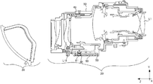
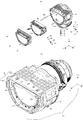
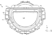
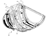
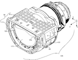
- FIG. 1 shows an example of the image projection apparatus as the embodiment of this invention. It is a figure which shows an example of the structure of the lens unit which comprises this invention. It is a figure which shows an example of the structure of the lens barrel shown in FIG. It is a figure which shows an example of the structure of the holding part and the curved part in the lens barrel shown in FIG. It is a figure which shows an example of the structure of the curved part shown in FIG. It is a figure which shows an example of the structure of a movable part. It is a figure which shows an example of the structure of the 1st fixing member. It is a figure which shows an example of the structure of the grip part. It is a figure which shows an example of the structure of the conventional image projection apparatus.
- FIG. 1 shows an image projection device 100 having a lens unit 103.
- the optical axis direction of the lens held by the lens unit 103 which is the lens barrel, is the Z direction, and of the directions perpendicular to the Z axis, the paper surface direction shown in FIG. 1 is the Y direction, and the Z direction and Y.
- the direction perpendicular to the direction is defined as the X direction.
- the projection surface 104 side of the lens unit 103 on the + Z direction side is referred to as an enlargement side
- the image display element 102 side on the ⁇ Z direction side is referred to as a reduction side.
- the image projection device 100 of the present invention includes a light source 101, an image display element 102 that displays an image to be projected and imparts image information to a light flux from the light source 101, and an image display element 102. It has a lens unit 103 provided with a plurality of lenses for forming an image of a transmitted light beam on the projection surface 104.
- the lens unit 103 includes a lens barrel 20 as a lens holding portion for holding a lens group including a plurality of lenses, and a reflection mirror 31 that reflects the light beam emitted from the lens barrel 20 and projects it toward the projection surface 104. It has a reflecting portion 30 having a lens. That is, in the present embodiment, the lens barrel 20 constitutes a part of a projection optical system including a reflection unit 30 which is a reflection optical system having at least one reflection mirror, and a refraction optical system having a plurality of lens groups is used. It is a lens barrel. Further, as shown in FIG. 2, the lens group held by the lens barrel 20 of the present embodiment includes non-circular lenses L16 to L20. In the present embodiment, a case where the lens L18 is moved in the Z-axis direction to adjust the position will be described in particular, but the present invention is not limited to this configuration, and any non-circular lens may be moved. good.
- the lens barrel 20 has a movable portion 40 having an inner wall surface 41 for holding the non-circular lens L18, and the lens barrel 20 is arranged on the outer peripheral side of the movable portion 40 to hold the movable portion 40. It has a holding portion 50 and a curved portion 60 arranged on the outer peripheral side of the holding portion 50.
- the lens barrel 20 has a plurality of lens barrels for holding the lenses L1 to L17, L19, and L20, but a detailed configuration will be omitted.
- the holding portion 50 is a tubular member having a so-called D-cut shape in which the surface on the + Y direction side is cut off from the cylindrical shape.
- the holding portion 50 is composed of a flat upper surface 51a parallel to the ZX plane and a curved surface 51b having a curvature formed along the circumferential direction of the Z axis.
- the holding portion 50 has guide shafts 52a and 52b which are shaft portions extending in parallel in the Z-axis direction inward.
- the guide shaft 52a is formed in the vicinity of the position where the upper surface 51a and the curved surface 51b are in contact with each other, and the guide shaft 52b is formed on the opposite side of the guide shaft 52a with the optical axis of the lens interposed therebetween.
- the guide shaft 52a and the guide shaft 52b may be arranged point-symmetrically with respect to the lens optical axis.
- the holding portion 50 has a movable portion groove 54 which is a gap extending along the Z direction.
- a roller 80 which will be described later, is arranged so as to be inserted into the movable portion groove 54, and is fixed to the movable portion 40. Since the roller 80 moves along the Z direction by the cam groove 62 due to the rotation of the curved portion 60 in the A direction, the movable portion 40 is also driven in the Z direction accordingly.
- the curved portion 60 is a plate-shaped member having a curvature along the curved surface 51b arranged outside the curved surface 51b of the holding portion 50, and has a length shorter than the entire circumference of the curved surface 51b. In other words, the curved surface 51b is provided with a margin portion on the outer peripheral portion so that the curved portion 60 can be slidably moved.
- the curved portion 60 has a guide groove 61 parallel to the Z-axis along the circumferential direction, and a cam groove 62 which is a groove portion formed so as to be inclined with respect to the guide groove 61.
- a roller 70, a wave washer 71, a flat washer 72, and a fixing screw 73 are engaged and arranged in the guide groove 61 as shown in FIG.
- a roller 80, a wave washer 81, a flat washer 82, and a fixing screw 83 are engaged and arranged in the cam groove 62 as shown in FIG.
- the curved portion 60 has a guide groove 61 and a cam groove 62, and can be moved in the A direction circumferentially to the side surface of the holding portion 50 by a fixing member arranged so as to engage with the plurality of grooves. Is retained.
- a gear shape 63 is formed on the outer peripheral surface of the curved portion 60, and is driven by a driving member such as a motor (not shown).
- the gear shape 63 has a function as an operating portion for rotating the curved portion 60 along the A direction.
- the curved portion 60 may be driven by attaching the grip portion 64 to the outer peripheral surface of the curved portion 60 as shown in FIG.
- the movable portion 40 is a tubular member having an inner wall surface 41 for holding the lens L18 and having a so-called D-cut shape generally along the shape of the lens L18.
- the movable portion 40 has a size such that the outer shape falls within the region surrounded by the upper surface 51a and the curved surface 51b of the holding portion 50, and the guide shaft 52a and the guide shaft 52b, respectively.
- the roller 70, the wave washer 71, the flat washer 72, and the fixing screw 73 are formed by fixing the fixing screw 73 to the holding portion 50 and engaging the roller 70 and the wave washer 71 with the curved portion 60. As shown in, it has a function as a first fixing member.
- the roller 80, the wave washer 81, the flat washer 82, and the fixing screw 83 have the fixing screw 83 fixed to the movable portion 40, and the roller 80 and the wave washer 81 engage with the curved portion 60. It has a function as a second fixing member.
- the mode of fixing the roller 80 as the second fixing member, the wave washer 81, the flat washer 82, and the fixing screw 83 is the same as in FIG. 7, and the holding portion 50, which is the fastening destination, becomes the movable portion 40. Since it is only changed, the illustration is omitted.
- the distance Z X of the guide groove 61 and the cam groove 62 varies according to the amount of movement in the direction A of the curved portion 60. That is, by moving the curved portion 60 in the A direction, the distance between the roller 70 engaged with the guide groove 61 and the roller 80 engaged with the cam groove 62 in the Z direction changes. Since the roller 70 is fixed to the holding portion 50 and the roller 80 is fixed to the movable portion 40, the roller 80 moves in the Z direction with respect to the roller 70 along the cam groove 62 due to the movement of the curved portion 60 in the A direction. To do. Therefore, the movable portion 40 moves in the Z direction with respect to the holding portion 50.
- the moving direction of the movable portion 40 at this time is restricted only in the Z direction along the guide shaft 52a and the guide shaft 52b.
- the guide shaft 52a and the guide shaft 52b regulate the movable portion 40 so that the moving direction is only the Z direction.
- the movable portion 40 holding the non-circular lens L18 can be moved in the Z direction. Therefore, the lens barrel 20 is limited to the non-circular lens L18 only. Can be moved in the Z direction. Further, in the present embodiment, only the configuration for moving one non-circular lens L18 has been described, but it goes without saying that if a plurality of cam grooves 62 are formed, a plurality of lenses can be moved at the same time.
- the lens barrel 200 is shown in FIG. 9 as an example of a conventional lens barrel having a lens position adjusting function using a so-called cam.
- the lens barrel 200 has a non-circular lens L and a cylindrical cam structure 201 having a cam groove arranged around the non-circular lens L, and the cam structure 201 rotates around the Z axis to cause a non-circular shape.
- the lens L has a configuration that moves back and forth in the Z direction. In the lens barrel 200, in order for the cam structure 201 to function, it is necessary to drive the non-circular lens L by rotating the cylindrical cam structure 201.
- cam structure 201 since the cam structure 201 is also present in the D-cut portion cut by the non-circular lens, there is a problem that it is difficult to prevent eclipse of light rays, especially in an image projection device that also uses a reflective optical system.
- a configuration in which a cam structure 201 is arranged around a circular lens on the reduction side and is driven so as to extend the non-circular lens L on the enlargement side can be considered.
- the remote position is driven in the front-rear direction, there is a problem that the external dimensions are inevitably increased.
- the curved portion 60 is arranged outside the lens (non-circular lens L18) to be moved, and the curved portion 60 is moved in the A direction to cause the non-circular lens L18.
- the movement mechanism can be arranged on the expansion side (front group side), the layout restriction on the reduction side (rear group side) can be relaxed as compared with the configuration as in the example of FIG.
- At least one of the plurality of grooves formed in the curved portion 60 is a guide groove 61 extending along the circumferential direction with respect to the Z-axis direction, and the other is a cam inclined with respect to the guide groove 61.
- the groove 62 is a guide groove 61 extending along the circumferential direction with respect to the Z-axis direction, and the other is a cam inclined with respect to the guide groove 61.
- the groove 62 is a guide groove 61 extending along the circumferential direction with respect to the Z-axis direction, and the other is a cam inclined with respect to the guide groove 61.
- the groove 62 With this configuration, since the distance Z X of the guide groove 61 and the cam groove 62 can be freely changed by the rotation of the direction A of the curved portion 60, adjust the position in the Z direction of the holding portion 50 and the movable portion 40 Then, the position of the non-circular lens L18 can be adjusted.
- the first fixing member and the second fixing member are composed of rollers 70 and 80, and wave washers 71 and 81 sandwiched between the rollers and the curved portion 60, respectively. With this configuration, the wave washers 71 and 81 can rotate the curved portion 60 while suppressing rattling.
- the grip portion 64 may be provided as an operation portion for rotating the curved portion 60. According to such a configuration, by moving the curved portion 60 in the A direction using the grip portion 64, it is possible to easily adjust the non-circular lens L18 in the Z direction from the outside.
- the image projection device 100 has an image display element 102 and a lens unit 103, and the non-circular lens L18 is moved back and forth in the Z direction by moving the curved portion 60 in the A direction.
- the lens unit 103 has a space-saving position adjustment function.
- FIGS. 11A to 11C show an explanatory view of a portion where the guide shaft 52a, which is a shaft portion, engages with the movable portion 40 as a configuration example of the guide holes 42a and 42b of the present invention.
- the lens barrel 200 has a guide shaft 52a having a function as a shaft portion and a guide shaft 52b. Further, the guide shaft 52a and the movable portion 40 are engaged with each other by a groove portion 43a parallel to the straight line O'connecting the centers of the two guide shafts 52a and 52b. With such a configuration, as shown in FIGS.
- the contact area with respect to the guide shafts 52a and 52b can be reduced, and the movable portion 40 can be moved more smoothly.
- the movable portion 40 and the guide shaft 52b are engaged with each other by a round hole. That is, the movable portion 40 includes a through hole 43b together with the groove portion 43a.
- the linear motion is mainly regulated in the Z direction on the guide shaft 52b side, and in order to improve the linear motion accuracy, the through hole 43b and the guide shaft 52b are engaged at two points before and after the Z direction. There is.
- the guide shaft 52a on the secondary reference side mainly acts as a rotation restriction of the movable portion 40 by engaging with the groove portion 43a parallel to the straight line O'. If the reference side is also a through hole, an error in the distance between the guide shafts (part accuracy, thermal expansion, etc.) affects the operation. Therefore, either of the guide shafts 52a and 52b should be used so that the error can be escaped.
- the other one may have a groove shape parallel to the straight line O'connecting the centers of the two guide shafts 52a and 52b in this way. desirable.
- the image projection device 100 includes a light source 101, an image display element 102 that displays an image to be projected and imparts image information to the light beam from the light source 101, and a light beam transmitted through the image display element 102.
- the lens unit 105 is provided with a plurality of lenses for forming an image on the projection surface 104.
- the lens unit 105 functions as a lens barrel as a lens holding unit that holds a lens group including a plurality of lenses. That is, in the second embodiment, the lens unit 105 is a lens barrel using a refraction optical system having a plurality of lens groups, and has a function as a projection optical system that projects light toward the projection surface 104. are doing. Further, as shown in FIG. 13, the lens group held by the lens unit 105 of the present embodiment includes a non-circular lens L21 and the like. In the present embodiment, a case where the lens L21 is moved in the Z-axis direction to adjust the position will be described, but the present invention is not limited to this configuration, and the non-circular lens arranged at another position is moved. It may be a thing.
- the curved surface side of the non-circular lens L21 of the lens unit 105 is shown downward, but in the actual arrangement, for example, the projection direction of the image projection device 100 is as shown in FIG. If it is on the upper side, it is arranged with the curved surface side facing up.
- the lens unit 105 includes a movable portion 40 having an inner wall surface 41 for holding the non-circular lens L21, and a holding portion 50 arranged on the outer peripheral side of the movable portion 40 to hold the movable portion 40. , And a curved portion 60 arranged on the outer peripheral side of the holding portion 50.
- the lens unit 105 may have a plurality of lens barrels for holding a plurality of lenses in addition to the lens L21, but a detailed configuration will be omitted.
- the holding portion 50 is a tubular member having a so-called D-cut shape in which the surface on the ⁇ Y direction side is cut off from the cylindrical shape.
- the holding portion 50 is composed of a flat upper surface 51a parallel to the ZX plane and a curved surface 51b having a curvature formed along the circumferential direction of the Z axis.
- the holding portion 50 has guide shafts 52a and 52b which are shaft portions extending in parallel in the Z-axis direction inward.
- the guide shaft 52a is formed in the vicinity of the position where the upper surface 51a and the curved surface 51b are in contact with each other, and the guide shaft 52b is formed on the opposite side of the guide shaft 52a with the optical axis of the lens interposed therebetween.
- the guide shaft 52a and the guide shaft 52b may be arranged point-symmetrically with respect to the lens optical axis.
- the holding portion 50 has a movable portion groove 54 which is a gap extending along the Z direction.
- a roller 80 which will be described later, is arranged so as to be inserted into the movable portion groove 54, and is fixed to the movable portion 40. Since the roller 80 moves along the Z direction by the cam groove 62 due to the rotation of the curved portion 60 in the A direction, the movable portion 40 is also driven in the Z direction accordingly.
- the curved portion 60 is a plate-shaped member having a curvature along the curved surface 51b arranged outside the curved surface 51b of the holding portion 50, and has a length shorter than the entire circumference of the curved surface 51b. In other words, the curved surface 51b is provided with a margin portion on the outer peripheral portion so that the curved portion 60 can be slidably moved.
- the curved portion 60 has a guide groove 61 parallel to the Z-axis along the circumferential direction, and a cam groove 62 which is a groove portion formed so as to be inclined with respect to the guide groove 61.
- a roller 70, a wave washer 71, a flat washer 72, and a fixing screw 73 are engaged and arranged in the guide groove 61 as shown in FIG.
- a roller 80, a wave washer 81, a flat washer 82, and a fixing screw 83 are engaged and arranged in the cam groove 62 as shown in FIG.
- the curved portion 60 has a guide groove 61 and a cam groove 62, and can be moved in the A direction circumferentially to the side surface of the holding portion 50 by a fixing member arranged so as to engage with the plurality of grooves. Is retained.
- a gear shape 63 is formed on the outer peripheral surface of the curved portion 60, and is driven by a driving member such as a motor. The gear shape 63 has a function as an operating portion for rotating the curved portion 60 along the A direction.
- the movable portion 40 is a tubular member having an inner wall surface 41 for holding the lens L18 and having a so-called D-cut shape outline along the shape of the lens L18. is there. Similar to that shown in FIG. 6, the movable portion 40 has a size such that the outer shape of the movable portion 40 falls within the region surrounded by the upper surface 51a and the curved surface 51b of the holding portion 50, and the guide shaft 52a and the movable portion 40, respectively. It has guide holes 42a and 42b into which the guide shaft 52b is inserted. With this configuration, the movable portion 40 is movably held inside the holding portion 50 in the front-rear direction in the Z direction along the guide shaft 52a and the guide shaft 52b.
- the roller 70, the wave washer 71, the flat washer 72, and the fixing screw 73 are formed by fixing the fixing screw 73 to the holding portion 50 and engaging the roller 70 and the wave washer 71 with the curved portion 60. 1 It has a function as a fixing member.
- the roller 80, the wave washer 81, the flat washer 82, and the fixing screw 83 have the fixing screw 83 fixed to the movable portion 40, and the roller 80 and the wave washer 81 engage with the curved portion 60. It has a function as a second fixing member.
- the mode of fixing the roller 80 as the second fixing member, the wave washer 81, the flat washer 82, and the fixing screw 83 is the same as in FIG. 7, and the holding portion 50, which is the fastening destination, becomes the movable portion 40. Since it is only changed, the illustration is omitted.
- the guide groove 61 and the cam groove 62 is formed to be inclined, the distance Z X of the guide groove 61 and the cam groove 62, the movement amount in the A direction of the bending portion 60 as shown in FIG. 5 fluctuate. That is, by moving the curved portion 60 in the A direction, the distance between the roller 70 engaged with the guide groove 61 and the roller 80 engaged with the cam groove 62 in the Z direction changes. Since the roller 70 is fixed to the holding portion 50 and the roller 80 is fixed to the movable portion 40, the roller 80 moves in the Z direction with respect to the roller 70 along the cam groove 62 due to the movement of the curved portion 60 in the A direction. To do. Therefore, the movable portion 40 moves in the Z direction with respect to the holding portion 50.
- the moving direction of the movable portion 40 at this time is restricted only in the Z direction along the guide shaft 52a and the guide shaft 52b.
- the guide shaft 52a and the guide shaft 52b regulate the movable portion 40 so that the moving direction is only the Z direction.
- the lens unit 105 uses only the non-circular lens L21. It can be moved in the Z direction. Further, in the present embodiment, only the configuration for moving one non-circular lens L21 has been described, but it goes without saying that if a plurality of cam grooves 62 are formed, a plurality of lenses can be moved at the same time.
- the non-circular lens L21 can be moved back and forth in the Z direction by arranging the curved portion 60 outside the lens (non-circular lens L21) to be moved and moving the curved portion 60 in the A direction. By doing so, it has a more space-saving lens position adjustment function.
- the lens unit 105 can be moved in the Z direction only by operating the lens unit 105 on the lower side, the limitation on the layout of the lens unit 105 can be relaxed. Further, such a lens position adjusting mechanism also contributes to reduction of unintended light, so-called ghost light, that penetrates into the lens unit 105.
- At least one of the plurality of grooves formed in the curved portion 60 is a guide groove 61 extending along the circumferential direction with respect to the Z-axis direction, and the other is a cam inclined with respect to the guide groove 61.
- the groove 62 is a guide groove 61 extending along the circumferential direction with respect to the Z-axis direction, and the other is a cam inclined with respect to the guide groove 61.
- the groove 62 is a guide groove 61 extending along the circumferential direction with respect to the Z-axis direction, and the other is a cam inclined with respect to the guide groove 61.
- the groove 62 With this configuration, since the distance Z X of the guide groove 61 and the cam groove 62 can be freely changed by the rotation of the direction A of the curved portion 60, adjust the position in the Z direction of the holding portion 50 and the movable portion 40 Then, the position of the non-circular lens L21 can be adjusted.
- the first fixing member and the second fixing member are composed of rollers 70 and 80, and wave washers 71 and 81 sandwiched between the rollers and the curved portion 60, respectively. With this configuration, the wave washers 71 and 81 can rotate the curved portion 60 while suppressing rattling.
- the image projection device 100 has an image display element 102 and a lens unit 105, and the non-circular lens L21 is moved back and forth in the Z direction by moving the curved portion 60 in the A direction.
- the lens unit 105 has a space-saving position adjustment function.
- the lens barrel according to the present invention is not limited to the so-called reflective projection optical system.
Landscapes
- Physics & Mathematics (AREA)
- General Physics & Mathematics (AREA)
- Optics & Photonics (AREA)
- Projection Apparatus (AREA)
- Lens Barrels (AREA)
Abstract
L'invention concerne un barillet de lentille doté d'une fonction de réglage de position d'économie d'espace. Barillet de lentille constituant une partie d'un système optique de projection pourvu d'un système catoptrique ayant au moins un miroir réfléchissant et ayant utilisé dans celui-ci un système dioptrique comprenant de multiples groupes de lentilles. Le barillet de lentille est caractérisé en ce qu'au moins l'un des groupes de lentilles a une lentille non circulaire et en a une partie mobile avec une surface de paroi interne pour maintenir la lentille non circulaire et qui peut déplacer le groupe de lentilles comprenant la lentille non circulaire le long de la direction d'axe optique de la lentille non circulaire. Une partie de maintien est disposée sur le côté circonférentiel externe de la partie mobile et maintient la partie mobile et une partie d'arbre formée le long de la direction d'axe optique et une partie incurvée est disposée sur le côté circonférentiel externe de la partie de maintien et a, dans une surface latérale ayant une courbure, de multiples rainures inclinées l'une par rapport à l'autre, un premier élément de fixation fixé à la partie de maintien devant être mis en prise avec l'une des multiples rainures, tandis qu'un second élément de fixation fixé à la partie mobile doit être en prise avec l'autre des rainures.
Priority Applications (3)
| Application Number | Priority Date | Filing Date | Title |
|---|---|---|---|
| CN202080027892.8A CN113661424B (zh) | 2019-04-12 | 2020-04-09 | 透镜镜筒和图像投影装置 |
| JP2021513705A JP7390365B2 (ja) | 2019-04-12 | 2020-04-09 | レンズ鏡筒及び画像投射装置 |
| US17/437,491 US12105344B2 (en) | 2019-04-12 | 2020-04-09 | Lens barrel and image projection apparatus |
Applications Claiming Priority (2)
| Application Number | Priority Date | Filing Date | Title |
|---|---|---|---|
| JP2019076497 | 2019-04-12 | ||
| JP2019-076497 | 2019-04-12 |
Publications (1)
| Publication Number | Publication Date |
|---|---|
| WO2020209343A1 true WO2020209343A1 (fr) | 2020-10-15 |
Family
ID=72751336
Family Applications (1)
| Application Number | Title | Priority Date | Filing Date |
|---|---|---|---|
| PCT/JP2020/016006 Ceased WO2020209343A1 (fr) | 2019-04-12 | 2020-04-09 | Barillet d'objectif et appareil de projection d'image |
Country Status (4)
| Country | Link |
|---|---|
| US (1) | US12105344B2 (fr) |
| JP (1) | JP7390365B2 (fr) |
| CN (1) | CN113661424B (fr) |
| WO (1) | WO2020209343A1 (fr) |
Families Citing this family (2)
| Publication number | Priority date | Publication date | Assignee | Title |
|---|---|---|---|---|
| TWM634353U (zh) * | 2022-04-18 | 2022-11-21 | 廣達電腦股份有限公司 | 穿戴式裝置的光學調整機構 |
| KR20240073475A (ko) * | 2022-11-18 | 2024-05-27 | 엘지이노텍 주식회사 | 카메라 모듈 및 이를 갖는 전자 장치 |
Citations (5)
| Publication number | Priority date | Publication date | Assignee | Title |
|---|---|---|---|---|
| JPS6118909A (ja) * | 1984-07-06 | 1986-01-27 | Canon Inc | 位置決め装置 |
| JP2006010885A (ja) * | 2004-06-24 | 2006-01-12 | Nidec Copal Corp | レンズ鏡胴 |
| JP2008008955A (ja) * | 2006-06-27 | 2008-01-17 | Fujinon Corp | プロジェクタ |
| JP2008191328A (ja) * | 2007-02-02 | 2008-08-21 | Nikon Corp | 移動機構、光学機器、撮像装置 |
| JP2016139114A (ja) * | 2015-01-27 | 2016-08-04 | セイコーエプソン株式会社 | 投写光学装置、およびプロジェクター |
Family Cites Families (11)
| Publication number | Priority date | Publication date | Assignee | Title |
|---|---|---|---|---|
| JP2010039403A (ja) * | 2008-08-08 | 2010-02-18 | Nikon Corp | レンズ鏡筒および撮像装置 |
| JP5312891B2 (ja) | 2008-10-03 | 2013-10-09 | 三洋電機株式会社 | 屈折光学系及び投写型映像表示装置 |
| JP5571512B2 (ja) | 2009-09-16 | 2014-08-13 | リコー光学株式会社 | 投射結像光学系およびプロジェクタ装置 |
| JP6435543B2 (ja) | 2014-05-15 | 2018-12-12 | リコーインダストリアルソリューションズ株式会社 | レンズユニット、画像投影装置及び撮像装置 |
| JP6476902B2 (ja) * | 2014-07-16 | 2019-03-06 | セイコーエプソン株式会社 | プロジェクター |
| JP6540044B2 (ja) * | 2015-01-27 | 2019-07-10 | セイコーエプソン株式会社 | 投写光学装置およびプロジェクター |
| US9690176B2 (en) * | 2015-01-27 | 2017-06-27 | Seiko Epson Corporation | Projection optical apparatus and projector |
| JPWO2016121379A1 (ja) * | 2015-01-29 | 2017-11-09 | キヤノン株式会社 | レンズ装置および画像投射装置 |
| KR102735927B1 (ko) * | 2016-09-02 | 2024-11-29 | 엘지전자 주식회사 | 프로젝터 |
| US11927742B2 (en) * | 2018-06-04 | 2024-03-12 | Mitsubishi Electric Corporation | Illumination device having wedge prisms and driving portion with multiple gears |
| CN112368622B (zh) * | 2018-06-28 | 2022-10-04 | 株式会社尼康 | 透镜镜筒 |
-
2020
- 2020-04-09 WO PCT/JP2020/016006 patent/WO2020209343A1/fr not_active Ceased
- 2020-04-09 US US17/437,491 patent/US12105344B2/en active Active
- 2020-04-09 CN CN202080027892.8A patent/CN113661424B/zh active Active
- 2020-04-09 JP JP2021513705A patent/JP7390365B2/ja active Active
Patent Citations (5)
| Publication number | Priority date | Publication date | Assignee | Title |
|---|---|---|---|---|
| JPS6118909A (ja) * | 1984-07-06 | 1986-01-27 | Canon Inc | 位置決め装置 |
| JP2006010885A (ja) * | 2004-06-24 | 2006-01-12 | Nidec Copal Corp | レンズ鏡胴 |
| JP2008008955A (ja) * | 2006-06-27 | 2008-01-17 | Fujinon Corp | プロジェクタ |
| JP2008191328A (ja) * | 2007-02-02 | 2008-08-21 | Nikon Corp | 移動機構、光学機器、撮像装置 |
| JP2016139114A (ja) * | 2015-01-27 | 2016-08-04 | セイコーエプソン株式会社 | 投写光学装置、およびプロジェクター |
Also Published As
| Publication number | Publication date |
|---|---|
| CN113661424A (zh) | 2021-11-16 |
| JPWO2020209343A1 (fr) | 2020-10-15 |
| US12105344B2 (en) | 2024-10-01 |
| US20220057595A1 (en) | 2022-02-24 |
| JP7390365B2 (ja) | 2023-12-01 |
| CN113661424B (zh) | 2023-08-22 |
Similar Documents
| Publication | Publication Date | Title |
|---|---|---|
| US10067324B2 (en) | Projection device and projection system | |
| JPH07191249A (ja) | レンズ鏡筒 | |
| JP2010230157A (ja) | 動力伝達装置 | |
| JP5868016B2 (ja) | 光学装置 | |
| JP2011085922A (ja) | 投射結像光学系およびプロジェクタ装置 | |
| JP7390365B2 (ja) | レンズ鏡筒及び画像投射装置 | |
| JP2006184775A (ja) | 反射型光学系およびこれを用いた投写型表示装置 | |
| US20070296931A1 (en) | Focusing/zooming apparatus for optical projection device and projection optical system | |
| JP6056303B2 (ja) | 投射光学系鏡筒 | |
| US8117936B2 (en) | Gear support structure | |
| JP6064535B2 (ja) | 投射光学系及びそれを備えた画像表示装置 | |
| JP5618145B2 (ja) | ミラーユニット | |
| JP6497573B2 (ja) | 投射装置および投射システム | |
| JP6390882B1 (ja) | 画像投写装置 | |
| KR101968432B1 (ko) | 투영 광학계, 노광 장치, 및 디바이스 제조 방법 | |
| WO2020003921A1 (fr) | Cylindre de lentille | |
| CN110531572A (zh) | 光学元件调整机构及投影装置 | |
| WO2005033761A1 (fr) | Barillet | |
| JP2003330116A (ja) | レンズ鏡筒支持装置および投影装置 | |
| JP2022147024A (ja) | 表示装置 | |
| WO2021246001A1 (fr) | Dispositif d'affichage, affichage tête haute et objet mobile | |
| EP2284590A1 (fr) | Système optique | |
| JP5991774B2 (ja) | 光学装置 | |
| US11287731B2 (en) | Optical module and projector | |
| CN113721340B (zh) | 透镜单元、图像投影装置以及光学装置 |
Legal Events
| Date | Code | Title | Description |
|---|---|---|---|
| 121 | Ep: the epo has been informed by wipo that ep was designated in this application |
Ref document number: 20787091 Country of ref document: EP Kind code of ref document: A1 |
|
| ENP | Entry into the national phase |
Ref document number: 2021513705 Country of ref document: JP Kind code of ref document: A |
|
| NENP | Non-entry into the national phase |
Ref country code: DE |
|
| 122 | Ep: pct application non-entry in european phase |
Ref document number: 20787091 Country of ref document: EP Kind code of ref document: A1 |