WO2020213031A1 - Soufflante d'air, unité intérieure pour dispositif de climatisation et dispositif de climatisation - Google Patents
Soufflante d'air, unité intérieure pour dispositif de climatisation et dispositif de climatisation Download PDFInfo
- Publication number
- WO2020213031A1 WO2020213031A1 PCT/JP2019/016144 JP2019016144W WO2020213031A1 WO 2020213031 A1 WO2020213031 A1 WO 2020213031A1 JP 2019016144 W JP2019016144 W JP 2019016144W WO 2020213031 A1 WO2020213031 A1 WO 2020213031A1
- Authority
- WO
- WIPO (PCT)
- Prior art keywords
- impeller
- casing
- blower
- rotation axis
- air
- Prior art date
- Legal status (The legal status is an assumption and is not a legal conclusion. Google has not performed a legal analysis and makes no representation as to the accuracy of the status listed.)
- Ceased
Links
Images






Classifications
-
- F—MECHANICAL ENGINEERING; LIGHTING; HEATING; WEAPONS; BLASTING
- F04—POSITIVE - DISPLACEMENT MACHINES FOR LIQUIDS; PUMPS FOR LIQUIDS OR ELASTIC FLUIDS
- F04D—NON-POSITIVE-DISPLACEMENT PUMPS
- F04D17/00—Radial-flow pumps, e.g. centrifugal pumps; Helico-centrifugal pumps
- F04D17/02—Radial-flow pumps, e.g. centrifugal pumps; Helico-centrifugal pumps having non-centrifugal stages, e.g. centripetal
- F04D17/04—Radial-flow pumps, e.g. centrifugal pumps; Helico-centrifugal pumps having non-centrifugal stages, e.g. centripetal of transverse-flow type
-
- F—MECHANICAL ENGINEERING; LIGHTING; HEATING; WEAPONS; BLASTING
- F24—HEATING; RANGES; VENTILATING
- F24F—AIR-CONDITIONING; AIR-HUMIDIFICATION; VENTILATION; USE OF AIR CURRENTS FOR SCREENING
- F24F1/00—Room units for air-conditioning, e.g. separate or self-contained units or units receiving primary air from a central station
- F24F1/0007—Indoor units, e.g. fan coil units
- F24F1/0018—Indoor units, e.g. fan coil units characterised by fans
- F24F1/0025—Cross-flow or tangential fans
Definitions
- the present invention relates to a blower, an indoor unit of an air conditioner equipped with the blower, and the air conditioner thereof.
- an air conditioner equipped with a blower in which a cross current blower and a centrifugal blower are combined is known (see, for example, Patent Document 1).
- an air conditioner exchanges heat with air sucked from the front surface and the upper surface, and then blows it into the room from an outlet by a cross flow fan.
- the air sucked from the auxiliary suction port provided on the side surface of the main body is heat-exchanged by the auxiliary heat exchanger provided inside, and then blown out from the lower part by the centrifugal fan provided at the end of the cross flow fan. Blow into the room from the mouth.
- one air outlet is used by the centrifugal blower and the cross flow blower by arranging the heat exchanger on the side surface of the housing.
- the air conditioner of Patent Document 1 generates a high static pressure because a centrifugal blower is used.
- a centrifugal blower since air is blown only from the blowing portions of the plurality of centrifugal blowers arranged in the rotation axis direction, there is a problem that the generated air volume is small with respect to the housing size in the rotation axis direction.
- the heat exchanger is arranged on the upstream side of the casing of the centrifugal blower, it is difficult for the wind to flow at the position on the upstream side of the casing. There was a problem of inviting.
- an object of the present invention is to provide a blower capable of increasing the air volume while generating a static pressure higher than that of the conventional one, an indoor unit of an air conditioner, and an air conditioner. And.
- the blower according to the present invention is a blower including at least a casing in which an air outlet is formed, an impeller arranged in an air passage formed in the casing, and a motor for driving the impeller.
- the impeller has a plurality of wing members arranged along the rotation axis on a circumference centered on the rotation axis of the impeller, and the plurality of wing members in a direction along the rotation axis.
- the casing has a connecting portion supported by an end portion, and the casing is arranged at a position facing the tongue portion and the tongue portion arranged close to a part of the outer periphery of the impeller, and the air passage.
- a stabilizer for dividing the air passage into a suction side air passage and a blow side air passage, and a surrounding portion provided along the rotation axis of the impeller and covering the outer periphery of the impeller, and the surrounding portion in the casing is provided.
- An exposed portion as a first suction port that exposes the outer periphery of the impeller is formed in the portion to be removed, and an opening as a second suction port is formed in the rotation axis direction of the impeller. It is something that has been done.
- the indoor unit of the air conditioner according to the present invention is provided with the above-mentioned blower.
- the air conditioner according to the present invention includes the indoor unit of the above air conditioner.
- a surrounding portion covering the outer periphery of the impeller is provided along the rotation axis of the casing, and an opening as a second suction port is formed in the rotation axis direction of the impeller. Therefore, the impeller can function as a sirocco fan and generate a high static pressure. Further, the impeller functions as a cross-flow fan by forming an exposed portion as a first suction port that exposes the outer periphery of the impeller in a part of the casing other than the surrounding portion along the rotation axis. The decrease in air volume can be improved. As a result, the air volume can be increased while generating a higher static pressure than before.
- FIG. It is a schematic diagram which shows the refrigerant circuit of the air conditioner which concerns on Embodiment 1.
- FIG. It is a vertical sectional view of the indoor unit of the air conditioner of FIG. It is a perspective view which shows the appearance of the air conditioner of FIG. 2 in an indoor unit.
- FIG. 2 shows the blower used for the indoor unit of the air conditioner of FIG.
- It is a vertical sectional view of the indoor unit in the exposed part of the blower of FIG.
- It is a vertical sectional view of the indoor unit in the surrounding part of the blower of FIG.
- It is the schematic which provides the explanation of the positional relationship of the stabilizer and the casing in the exposed part and the surrounding part of the blower of FIG.
- FIG. 12 shows the main part of the blower of FIG. 12 as seen from the top surface. It is the schematic which shows the main part of the blower used for the indoor unit of the air conditioner which concerns on the modification of Embodiment 2 from the top view.
- FIG. 1 is a schematic view showing a refrigerant circuit 5 of the air conditioner 1 according to the first embodiment. Note that FIG. 1 shows an example of an air conditioner 1 including an indoor unit 2 of an air conditioner 1 using an indoor blower 17 as a blower according to the first embodiment.
- the air conditioner 1 cools or heats the air in the room by transferring heat between the outside air and the air in the room via a refrigerant. It has an indoor unit 2 and an outdoor unit 3.
- the indoor unit 2 and the outdoor unit 3 are connected by pipes via the refrigerant pipes 4, 4a and 4b to form a refrigerant circuit 5 in which the refrigerant circulates.
- the refrigerant circuit 5 is provided with a compressor 10, a flow path switching device 11, an outdoor heat exchanger 12, an expansion valve 13, and an indoor heat exchanger 14, and these are connected via refrigerant pipes 4, 4a, and 4b. There is.
- the outdoor unit 3 has a compressor 10, a flow path switching device 11, an outdoor heat exchanger 12, and an expansion valve 13.
- the compressor 10 compresses and discharges the sucked refrigerant.
- the compressor 10 may include an inverter device. When the inverter device is provided, the operation frequency can be changed by the control unit 6 to change the capacity of the compressor 10.
- the capacity of the compressor 10 is the amount of refrigerant delivered per unit time. Further, the compressor 10 may have the input current value for the compressor 10 controlled by the control unit 6.
- the flow path switching device 11 is, for example, a four-way valve, and is a device that switches the flow direction of the refrigerant in the refrigerant pipes 4, 4a, and 4b as the direction of the refrigerant flow path.
- the air conditioner 1 can realize a heating operation or a cooling operation by switching the flow of the refrigerant by using the flow path switching device 11 based on the instruction from the control unit 6.
- the outdoor heat exchanger 12 exchanges heat between the refrigerant and the outdoor air. Further, the outdoor heat exchanger 12 is provided with an outdoor blower 15 in order to improve the efficiency of heat exchange between the refrigerant and the outdoor air.
- An inverter device may be attached to the outdoor blower 15.
- the inverter device changes the rotation speed of the fan by changing the operating frequency of the fan motor 16 which is the drive source of the outdoor blower 15.
- the outdoor blower 15 is not limited to this as long as the same effect can be obtained.
- the type of fan may be a sirocco fan or a plug fan.
- the outdoor blower 15 may be a pushing type or a pulling type.
- the outdoor heat exchanger 12 functions as an evaporator during the heating operation, and exchanges heat between the low-pressure refrigerant flowing in from the refrigerant pipe 4b side and the outdoor air to evaporate the refrigerant and vaporize it. And let it flow out to the refrigerant pipe 4a side. Further, the outdoor heat exchanger 12 functions as a condenser during the cooling operation, and the refrigerant compressed by the compressor 10 flowing in from the refrigerant pipe 4a side via the flow path switching device 11 and the outdoor air. Heat exchange is performed between the refrigerants to condense and liquefy the refrigerant, and the refrigerant flows out to the refrigerant pipe 4b side.
- the outdoor air is used as the external fluid
- the external fluid is not limited to the gas containing the outdoor air, and may be a liquid containing water.
- the expansion valve 13 is a throttle device that controls the flow rate of the refrigerant, and adjusts the pressure of the refrigerant by adjusting the flow rate of the refrigerant flowing through the refrigerant pipe 4 by changing the opening degree of the expansion valve 13.
- the expansion valve 13 expands the high-pressure liquid state refrigerant into the low-pressure gas-liquid two-phase state refrigerant to reduce the pressure.
- the expansion valve 13 is not limited to this, and an electronic expansion valve, a capillary tube, or the like may be used as long as the same effect can be obtained.
- the opening degree is adjusted based on the instruction of the control unit 6.
- the indoor unit 2 includes an indoor heat exchanger 14 that exchanges heat between the refrigerant and the indoor air, and an indoor blower 17 that adjusts the flow of air that the indoor heat exchanger 14 exchanges heat with.
- the indoor heat exchanger 14 acts as a condenser during the heating operation, exchanges heat between the refrigerant flowing in from the refrigerant pipe 4a side and the indoor air, condenses the refrigerant and liquefies it, and causes the refrigerant pipe. Let it flow out to the 4b side. Further, the indoor heat exchanger 14 functions as an evaporator during the cooling operation, and exchanges heat between the refrigerant brought into a low pressure state by the expansion valve 13 flowing in from the refrigerant pipe 4b side and the indoor air. The refrigerant takes heat from the air, evaporates it, vaporizes it, and causes it to flow out to the refrigerant pipe 4a side.
- the indoor air is used as the external fluid
- the external fluid is not limited to the gas containing the indoor air and may be a liquid containing water.
- the operating speed of the indoor blower 17 is determined by the user's setting. It is preferable to attach an inverter device to the indoor blower 17 and change the operating frequency of the fan motor 18 to change the rotation speed of the fan. The details of the indoor blower 17 will be described later.
- This gas-liquid two-phase refrigerant flows into the indoor heat exchanger 14 of the indoor unit 2, evaporates by heat exchange with the indoor air blown by the indoor blower 17, becomes a low-temperature low-pressure gas refrigerant, and becomes an indoor heat exchanger. Outflow from 14. At this time, the indoor air that has been endothermic and cooled by the refrigerant becomes air-conditioned air (blown air) and is blown out from the indoor unit 2 into the room that is the air-conditioned space. The gas refrigerant flowing out of the indoor heat exchanger 14 is sucked into the compressor 10 via the flow path switching device 11 and is compressed again. In the cooling operation of the air conditioner 1, the above operation is repeated (indicated by the solid arrow in FIG. 1).
- the high-temperature and high-pressure gas refrigerant compressed and discharged by the compressor 10 flows into the indoor heat exchanger 14 of the indoor unit 2 via the flow path switching device 11.
- the gas refrigerant flowing into the indoor heat exchanger 14 is condensed by heat exchange with the indoor air blown by the indoor blower 17, becomes a low-temperature refrigerant, and flows out from the indoor heat exchanger 14.
- the indoor air that has been warmed by receiving heat from the gas refrigerant becomes conditioned air (blown air) and is blown out from the indoor unit 2 into the room.
- the refrigerant flowing out of the indoor heat exchanger 14 is expanded and depressurized by the expansion valve 13 to become a low-temperature low-pressure gas-liquid two-phase refrigerant.
- This gas-liquid two-phase refrigerant flows into the outdoor heat exchanger 12 of the outdoor unit 3, evaporates by heat exchange with the outside air blown by the outdoor blower 15, becomes a low-temperature low-pressure gas refrigerant, and becomes the outdoor heat exchanger 12.
- the gas refrigerant flowing out of the outdoor heat exchanger 12 is sucked into the compressor 10 via the flow path switching device 11 and is compressed again. In the heating operation of the air conditioner 1, the above operation is repeated (indicated by the broken line arrow in FIG. 1).
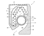
- FIG. 2 is a vertical cross-sectional view of the indoor unit 2 of the air conditioner 1 of FIG.
- FIG. 3 is a perspective view showing the appearance of the indoor unit 2 of the air conditioner 1 of FIG. Note that FIGS. 2 and 3 show an example of the indoor blower 17 as the blower according to the first embodiment and the indoor unit 2 of the air conditioner 1 using the indoor blower 17.
- the indoor unit 2 in the first embodiment is connected to the outdoor unit 3 by the refrigerant pipes 4, 4a and 4b, and the refrigerant is circulated in the refrigerant circuit 5 together with the outdoor unit 3 to freeze or freeze. It constitutes an air conditioning device 1 that performs air conditioning and the like.
- the indoor unit 2 includes a housing 20 formed in a rectangular box shape. It mainly includes a housing 20 in which a suction port 21 for sucking indoor air and an air outlet 22 for supplying conditioned air to a target area are formed.
- a suction port 21 is formed in the upper part of the housing 20 with an opening.
- an air outlet 22 is formed by opening in the lower part of the front surface of the housing 20.
- the outlet 22 is provided with a vane or the like (not shown) as a mechanism for controlling the blowing direction of the air flow.
- the housing 20 houses an indoor heat exchanger 14 and an indoor blower 17 which is arranged downstream of the indoor heat exchanger 14 and sucks indoor air from a suction port 21 and blows out conditioned air from an air outlet 22. There is. Further, inside the housing 20, a filter 23 for collecting dust or dust is provided on the downstream side of the suction port 21 and on the upstream side of the indoor heat exchanger 14.
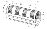
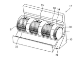
- FIG. 4 is a perspective view showing an indoor blower 17 used for the indoor unit 2 of the air conditioner 1 of FIG.
- FIG. 5 is a vertical cross-sectional view of the indoor unit 2 in the exposed portion 35 of the indoor blower 17 of FIG.
- FIG. 6 is a vertical cross-sectional view of the indoor unit 2 in the surrounding portion 34 of the indoor blower 17 of FIG.
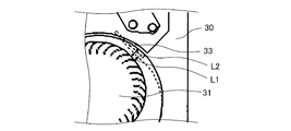
- FIG. 7 is a schematic view for explaining the positional relationship between the stabilizer 33 and the casing 30 in the exposed portion 35 and the surrounding portion 34 of the indoor blower 17 of FIG.
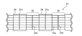
- FIG. 8 is a schematic view showing a main part of the indoor blower 17 of FIG.
- FIG. 4 shows an example of the indoor blower 17 according to the first embodiment and the indoor unit 2 of the air conditioner 1 using the indoor blower 17. Further, FIG. 4 shows the housing 20 or the indoor heat exchanger 14 (not shown) with respect to FIGS. 2 and 3 so that the indoor blower 17 and its peripheral structure can be recognized.
- the indoor blower 17 includes a casing 30 in which an air outlet 22 is formed.
- the casing 30 includes an impeller 31 as a fan arranged in an air passage E formed inside, and a fan motor 18 as a motor for driving the impeller 31.
- the impeller 31 includes a plurality of blade members 31a arranged along the rotation axis on the circumference centered on the rotation axis of the impeller 31, and these plurality of blade members 31a in a direction along the rotation axis. It has connecting portions 31b and 31c that are supported at the ends. A part or all of the connecting portions 31b and 31c in the impeller 31 are disk-shaped end plates, and the end plates are arranged inside the casing 30.
- the casing 30 is arranged at a position facing the tongue portion 32 and the tongue portion 32 which are arranged close to a part of the outer periphery of the impeller 31, and makes the air passage E into the suction side air passage E1 and the outlet side air passage E2. It has a stabilizer 33 and a stabilizer 33.
- the casing 30 is provided along the rotation axis of the impeller 31, and includes a surrounding portion 34 that covers the outer periphery of the impeller 31. Exposed portions 35 as first suction ports that expose the outer periphery of the impeller 31 on both sides of the casing 30 except for the surrounding portion 34 along the rotation axis, more specifically, on both sides of the surrounding portion 34 in the rotation axis direction. Is formed.
- a plurality of surrounding portions 34 and exposed portions 35 are alternately arranged along the rotation axis direction of the impeller 31.
- the surrounding portion 34 is formed in a rectangular shape in a plan view as shown in FIG. 4 or FIG. 8 will be described, but the shape of the surrounding portion 34 is not limited to this, and various other shapes are described. Shapes can be applied. As another example, it will be described in the second embodiment described later.
- the impeller 31 can function as a sirocco fan by covering the outer circumference with the surrounding portion 34. Further, the outer circumference is exposed and opened by the exposed portion 35, so that the fan can function as a cross flow fan. That is, in the indoor blower 17 of the first embodiment, the impeller 31 has a feature that the sirocco fan and the cross flow fan are integrally formed.
- the stabilizer 33 is preferably configured as follows.
- the distance between the stabilizer 33 and the outer peripheral end of the impeller 31 in the cross section along the direction orthogonal to the rotation axis at the portion located at the exposed portion 35 is L1.
- the distance between the casing 30 and the outer peripheral end portion of the impeller 31 in the cross section along the direction orthogonal to the rotation axis at the portion located in the surrounding portion 34 is L2.
- the distance L1 between the stabilizer 33 and the outer peripheral end of the impeller 31 is shorter than the distance L2 between the casing 30 and the outer peripheral end of the impeller 31.
- the clearance of the distance L1 between the impeller 31 and the outer peripheral end of the stabilizer 33 is made small, and as shown in FIG. 6, the distance from the tongue portion 32 to the impeller 31 gradually increases. It is preferable that it is configured to do so.
- the air volume generated from the impeller 31 arranged in the exposed portion 35, that is, the cross flow fan can be increased. Further, inside the surrounding portion 34, the tongue portion 32 and the outlet 22 are smoothly connected to each other, so that the sirocco fan can gradually recover the static pressure.
- the positions of the surrounding portion 34 of the impeller 31 and the connecting portions 31b and 31c are such that the connecting portion 31c is exposed on the surrounding portion 34 as shown in FIG. It is preferable to arrange the connecting portions 31b at 35 respectively. In FIG. 8, only the surrounding portion 34 and the exposed portion 35 of the impeller 31 are extracted and shown.
- the connecting portion 31b is composed of a ring member having a circular hole in the center of the disk, and the connecting portion 31c has no hole. It is composed of disc-shaped end plates.
- the connecting portion 31b is arranged within the range of the exposed portion 35.
- the connecting portion 31c is arranged in a range covered by the surrounding portion 34. That is, in the surrounding portion 34, the air passage is partitioned by the connecting portion 31c, and the air flow is sucked from both sides in the rotation axis direction of the surrounding portion 34.
- FIGS. 5 and 6 show an indoor heat exchanger 14 and a suction port 21 which are not shown in order to improve visibility in FIG.
- the impeller 31 rotates about the center of the rotation axis by the driving force of the fan motor 18. Then, after passing through the suction port 21 and the indoor heat exchanger 14, the airflow is sucked in from the exposed portion 35 in FIG. 5, passes through the impeller 31, and is blown out from the air outlet 22.
- the exposed portion 35 has a flow similar to that of a conventional cross-flow fan
- the surrounding portion 34 has a flow similar to that of a sirocco fan (centrifugal fan).
- the cross flow fan is formed in the exposed portion 35 in which the outer periphery of the impeller 31 is not covered by the surrounding portion 34 of the casing 30, the exposed portion 35 in which the surrounding portion 34 of the casing 30 does not exist.
- the wind also flows in. Therefore, it is possible to generate a higher static pressure than a conventional cross-flow fan, and to generate a higher air volume than a configuration in which a plurality of centrifugal blowers are arranged.
- FIG. 9 is a partial cross-sectional view showing a schematic configuration of an intermediate portion of the impeller 31 in the rotation axis direction by cutting a main part of the indoor blower 17 of FIG. 4 along a plane in the vertical direction along the rotation axis.
- FIG. 10 is a partial cross section showing a main part of the indoor blower 17 of FIG. 4 cut along a plane in the vertical direction along the rotation axis and showing a schematic configuration of an end portion on the fan motor 18 side in the rotation axis direction of the impeller 31. It is a figure.
- the plurality of blade members 31a (see FIG. 6 and the like) arranged in a cylindrical shape include a surrounding portion 34 surrounded by a casing 30 in the axial direction and an exposed portion 35 not surrounded by the casing 30. Are lined up alternately.
- FIG. 9 shows a configuration in which exposed portions 35 are provided on both sides of the surrounding portion 34 in the axial direction. In the figure, the direction of the wind flow is indicated by a broken line arrow.
- the surrounding portion 34 is surrounded by a casing 30 having exposed portions 35 opened at both ends in the axial direction, and the wing member 31a of the inner wall (not shown) of the casing 30 is subjected to centrifugal force due to the rotation of the wing member 31a inside the surrounding portion 34. In the space between and, a wind flow is generated in the rotation direction of the impeller 31.
- the outlet 22 may be formed of a part of the casing 30.
- air is sucked into the lower part of the exposed portion 35 on the front side from above the tongue portion 32 (indicated by the broken line of the rectangle in the figure), and the wind is blown from the outlet 22 below the tongue portion 32 through the vicinity of the central axis. Blow out. That is, the wind flows across the axis like a cross-flow fan (broken line with a thin arrow).
- the outlet 22 of the exposed portion 35 is axially connected to the casing 30 of the surrounding portion 34.
- the casing 30, the tongue portion 32, and the stabilizer 33 may also be configured to be connected in the axial direction.
- the stabilizer 33 is on the depth side in FIG. 5, it is not shown here for convenience.
- the surrounding portion 34 is as shown by a broken line with a thick arrow.
- the exposed portion 35 sucks in the air inside the shaft surrounded by the impeller 31.
- the air sucked in by the surrounding portion 34 flows into the space between the blade member 31a and the casing 30 by centrifugal force, swirls in this space, and is blown out from the air outlet 22.
- the connecting portion 31b located in the exposed portion 35 is composed of a disk-shaped end plate
- the connecting portion 31c located in the surrounding portion 34 is a rotation shaft of the impeller 31. It is composed of a ring member with a circular hole on the concentric circle.
- a through hole 34a through which the impeller 31 penetrates is formed in the surrounding portion 34. Therefore, the airflow flowing in from the exposed portion 35 flows to the adjacent surrounding portion 34 side through the through hole 34a without being blocked by the connecting portion 31b. Then, the airflow flowing into the surrounding portion 34 is blocked from flowing in the direction of the rotation axis of the impeller 31, and is guided to the air outlet 22 along the surrounding portion 34 and the casing 30.
- an opening 31e that functions as a second suction port is formed at an end of the impeller 31 that faces the fan motor 18 in the rotation axis direction.
- an opening 31e is formed at the end of the casing 30 along the rotation axis direction to function as a second suction port with the end of the impeller 31 exposed in the rotation axis direction.
- the shape of the impeller 31 is not limited to this. That is, the end portion of the impeller 31 in the rotation axis direction may be open or may be covered by a surrounding portion 34.
- a shaft 18a is provided on the connecting portion 31d located at one of the ends of the impeller 31 in the rotation axis direction, and a fan motor 18 for rotationally driving the impeller 31 is provided. It is connected.
- the connecting portion 31d is formed of a disk-shaped end plate having no holes, and the connecting portion 31d and the drive shaft of the fan motor 18 are connected to each other.
- the rotation direction of the impeller 31 is, for example, a clockwise direction in the case of FIG. 2, and a counterclockwise direction in the case of FIG. 4 when viewed from the fan motor 18.
- the end portion on the fan motor 18 side may be opened by arranging an exposed portion 35 that is not covered by the casing 30, as shown in FIG.
- the casing 30 may be covered by arranging the surrounding portion 34 around the connection between the fan motor 18 and the impeller 31.
- FIG. 11 shows a main part of the indoor blower 17 according to the modified example of the first embodiment cut by a surface in the vertical direction along the rotation axis, and shows the end portion on the fan motor 18 side in the rotation axis direction of the impeller 31. It is a partial cross-sectional view which shows the schematic structure.
- the end portion of the casing 30, that is, the surrounding portion 34, which is located closest to the fan motor 18, does not suck air from the fan motor 18 side, and only the surface on the opposite side facing the fan motor 18.
- a through hole 34a is formed therein. Since the surrounding portion 34 at the end of the casing 30 sucks air only from one side, the length in the axial direction is set shorter than that of the casing 30 that sucks air from both sides in the middle of the axial direction. As an approximate reference for this axial length, it is determined that the axial length is not larger than 60% of the diameter of the impeller 31. As described above, the casing 30 that sucks only from one side has an advantage that a decrease in efficiency can be prevented by shortening the length in the axial direction.
- the surrounding portion 34 by arranging the surrounding portion 34 at the end portion in this way, the static pressure improvement is excellent as compared with the configuration in which the exposed portion 35 is arranged as shown in FIG. Further, by shortening the axial length of the casing 30, it is possible to prevent a decrease in efficiency. Although the case where the axial length of the casing 30 is shortened has been described, the connecting portion 31b as a ring member may not be provided if molding is possible. Further, when the connecting portion 31b as a ring member is formed, it is desirable to arrange the connecting portion 31b in the exposed portion 35.
- the casing 30 described above is integrally formed without a gap from the front side where the tongue portion 32 is arranged to the back side where the stabilizer 33 is arranged, but may be formed separately.
- a part may be integrated with a drain pan or a member for holding the indoor heat exchanger 14, which is a part on the front side (not shown), and the other part may be integrally configured with a part on the back side for assembly. Only the casing 30 may be a separate body.
- the surrounding portion 34 covering the outer periphery of the impeller 31 is provided along the rotation axis of the casing 30, and further, in the direction of the rotation axis of the impeller 31. Is formed with an opening 31e as a second suction port. Therefore, the impeller 31 can function as a sirocco fan and generate a high static pressure. Further, the impeller 31 is cross-flowed by forming an exposed portion 35 as a first suction port that exposes the outer periphery of the impeller 31 in a part of the casing 30 other than the surrounding portion 34 along the rotation axis. It can function as a fan and improve the decrease in air volume. As a result, the air volume can be increased while generating a higher static pressure than before.
- the wind speed distribution generated in the indoor heat exchanger 14 arranged on the upstream side of the indoor blower 17 can be distributed. It can be suppressed and the deterioration of the performance of the air conditioner 1 can be improved.
- a part or all of the connecting portions 31b and 31c of the impeller 31 is composed of an end plate which is a disk without holes.
- the connecting portion 31b without holes is housed inside the casing. According to this, by partitioning the air passage in the impeller 31 inside the surrounding portion 34 by the connecting portion 31b, the airflow can flow in from both sides in the rotation axis direction of the impeller 31 in the surrounding portion 34, and the fan efficiency. Can be improved.
- the distance L1 between the stabilizer 33 and the outer peripheral end of the impeller 31 is shorter than the distance L2 between the casing 30 and the outer peripheral end of the impeller 31.
- the clearance of the distance L1 between the impeller 31 and the outer peripheral end of the stabilizer 33 is made small, and the distance from the tongue portion 32 to the impeller 31 is gradually increased. Therefore, the air volume generated from the impeller 31 arranged on the exposed portion 35, that is, the cross flow fan can be increased.
- the tongue portion 32 and the outlet 22 are smoothly connected to each other, so that the sirocco fan can gradually recover the static pressure.
- FIG. 12 is a perspective view showing an indoor blower 17 used in the indoor unit 2 of the air conditioner 1 according to the second embodiment.
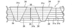
- FIG. 13 is a schematic view showing a main part of the indoor blower 17 of FIG. 12 as viewed from above.
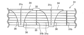
- FIG. 14 is a schematic view showing a main part of the indoor blower 17 used in the indoor unit 2 of the air conditioner 1 according to the modified example of the second embodiment as viewed from above.
- FIG. 12 is shown so that the housing 20 and the indoor heat exchanger 14 can be permeated so that the indoor blower 17 and its peripheral structure can be recognized.
- the configuration of the boundary portion 36 between the surrounding portion 34 and the exposed portion 35 will be particularly described.
- items not particularly described are the same as those in the first embodiment, and the same functions and configurations will be described using the same reference numerals.
- the indoor heat exchanger 14 is densely arranged near the surrounding portion 34 due to restrictions on the size of the indoor unit 2.
- the surrounding portion 34 and the indoor heat exchanger 14 may be close to each other.
- the distance between the indoor heat exchanger 14 arranged at the lower part of the front surface and the surrounding portion 34 is very close.
- a part or all of the boundary portion 36 between the surrounding portion 34 and the exposed portion 35 is relative to the rotation axis of the impeller 31. It is composed of diagonally intersecting parts.
- the boundary portion 36 between the surrounding portion 34 and the exposed portion 35 may be configured as follows.
- the boundary portion 36 of the impeller 31 may be formed of a straight line as shown in FIG. 13 or may be formed of a curved line as shown in FIG. Further, a straight line and a curved line may be combined.
- the indoor blower 17, the indoor unit 2 of the air conditioner 1, and the air conditioner 1 according to the second embodiment are a part or all of the boundary portion 36 between the surrounding portion 34 and the exposed portion 35. Is diagonally intersecting the rotation axis of the impeller 31. According to such a configuration, the effective ventilation area for the indoor heat exchanger 14 on the front side is increased, so that the wind speed distribution generated in the indoor heat exchangers 14 which are close to each other as in the conventional case can be improved.
- the casing 30 relaxes the wind speed distribution generated in the indoor heat exchanger 14 upstream of the surrounding portion 34.
- the deterioration of the performance of the air conditioner can be improved.
- the distance in the rotation axis direction connecting the boundary portion 36 that is the boundary between the surrounding portion 34 and the exposed portion 35 and the boundary portion 36 on the opposite side thereof becomes larger as the impeller 31 is rotated. It is preferable to do so.
- the static pressure can be efficiently recovered by providing the casing 30 in the axial direction longer in the rotation direction of the impeller 31, and the power consumption can be reduced by improving the fan efficiency.
- the indoor blower 17 in the above-described first and second embodiments, the indoor unit 2 of the air conditioner 1, and the air conditioner 1 It is not limited to the mode. That is, in the indoor blower 17, the surrounding portion 34 is not limited to the above-described embodiments 1 and 2, and the same effects as those of the first and second embodiments can be obtained even if they are configured as follows.
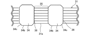
- FIG. 15 is a schematic view showing a main part of the indoor blower 17 used for the indoor unit 2 of the air conditioner 1 according to another embodiment as viewed from above.
- FIG. 16 is a schematic view showing a main part of the indoor blower 17 used in the indoor unit 2 of the air conditioner 1 according to another embodiment as viewed from above.
- FIG. 15 and FIG. 16 only the impeller 31 and the portion of the surrounding portion 34 thereof are taken out and shown.
- items not particularly described will be the same as those of the above-described embodiments 1 and 2, and the same functions and configurations will be described using the same reference numerals.
- a part or all of the part 34c may be formed into a curved surface.
- a part or all of the corner portion 34c formed by the surface may be chamfered.
Landscapes
- Engineering & Computer Science (AREA)
- Mechanical Engineering (AREA)
- General Engineering & Computer Science (AREA)
- Chemical & Material Sciences (AREA)
- Combustion & Propulsion (AREA)
- Structures Of Non-Positive Displacement Pumps (AREA)
- Air-Conditioning Room Units, And Self-Contained Units In General (AREA)
Abstract
La présente invention concerne une soufflante d'air qui est pourvue d'un boîtier sur lequel au moins un orifice de soufflage est formé, d'une roue qui est agencée sur un conduit d'air formé à l'intérieur du boîtier, et d'un moteur pour entraîner la roue. La roue a une pluralité d'éléments de pale dont chacun est agencé le long d'un arbre rotatif sur la circonférence autour de l'arbre rotatif, et une partie de liaison qui soutient la pluralité d'éléments de pale au niveau des extrémités de celle-ci dans une direction le long de l'arbre rotatif. Le boîtier est pourvu d'une partie de languette qui est agencée de façon adjacente à une partie d'une périphérie externe de la roue, d'un stabilisateur qui est agencé à une position faisant face à la partie de languette et sépare le conduit d'air en un conduit d'air côté aspiration et un conduit d'air côté soufflage, et d'une partie périphérique qui est disposée le long de l'arbre rotatif de la roue et recouvre la périphérie externe de la roue. Au niveau d'une partie autre que la partie périphérique dans le boîtier, une partie d'exposition qui sert de premier orifice d'aspiration qui expose la périphérie externe de la roue est formée. Dans une direction d'arbre rotatif dans la roue, une partie d'ouverture qui sert de deuxième orifice d'aspiration est formée.
Priority Applications (2)
| Application Number | Priority Date | Filing Date | Title |
|---|---|---|---|
| PCT/JP2019/016144 WO2020213031A1 (fr) | 2019-04-15 | 2019-04-15 | Soufflante d'air, unité intérieure pour dispositif de climatisation et dispositif de climatisation |
| JP2019551477A JP6625305B1 (ja) | 2019-04-15 | 2019-04-15 | 送風機、空気調和装置の室内機および空気調和装置 |
Applications Claiming Priority (1)
| Application Number | Priority Date | Filing Date | Title |
|---|---|---|---|
| PCT/JP2019/016144 WO2020213031A1 (fr) | 2019-04-15 | 2019-04-15 | Soufflante d'air, unité intérieure pour dispositif de climatisation et dispositif de climatisation |
Publications (1)
| Publication Number | Publication Date |
|---|---|
| WO2020213031A1 true WO2020213031A1 (fr) | 2020-10-22 |
Family
ID=69100993
Family Applications (1)
| Application Number | Title | Priority Date | Filing Date |
|---|---|---|---|
| PCT/JP2019/016144 Ceased WO2020213031A1 (fr) | 2019-04-15 | 2019-04-15 | Soufflante d'air, unité intérieure pour dispositif de climatisation et dispositif de climatisation |
Country Status (2)
| Country | Link |
|---|---|
| JP (1) | JP6625305B1 (fr) |
| WO (1) | WO2020213031A1 (fr) |
Cited By (3)
| Publication number | Priority date | Publication date | Assignee | Title |
|---|---|---|---|---|
| KR102327909B1 (ko) * | 2021-01-08 | 2021-11-17 | 한국서부발전 주식회사 | 다수의 에어 분사용 스페이스링을 구비한 배출가스용 에어 블로워 유닛 |
| JPWO2023286208A1 (fr) * | 2021-07-14 | 2023-01-19 | ||
| US12071957B1 (en) | 2023-03-23 | 2024-08-27 | Gd Midea Environment Appliances Mfg Co., Ltd. | Head mechanism and fan apparatus |
Families Citing this family (1)
| Publication number | Priority date | Publication date | Assignee | Title |
|---|---|---|---|---|
| JP7298641B2 (ja) * | 2021-03-30 | 2023-06-27 | 株式会社富士通ゼネラル | 空気調和装置 |
Citations (5)
| Publication number | Priority date | Publication date | Assignee | Title |
|---|---|---|---|---|
| JPH05321877A (ja) * | 1992-05-18 | 1993-12-07 | Daikin Ind Ltd | 送風機 |
| JPH06307660A (ja) * | 1993-04-26 | 1994-11-01 | Matsushita Electric Ind Co Ltd | 空気調和機 |
| JP2005240603A (ja) * | 2004-02-25 | 2005-09-08 | Toshiba Home Technology Corp | 横長ファンモータ |
| JP2005249323A (ja) * | 2004-03-05 | 2005-09-15 | Mitsubishi Electric Corp | 空気調和機 |
| CN1727689A (zh) * | 2004-07-26 | 2006-02-01 | 乐金电子(天津)电器有限公司 | 具有离心扇和横流扇的送风机 |
-
2019
- 2019-04-15 WO PCT/JP2019/016144 patent/WO2020213031A1/fr not_active Ceased
- 2019-04-15 JP JP2019551477A patent/JP6625305B1/ja not_active Expired - Fee Related
Patent Citations (5)
| Publication number | Priority date | Publication date | Assignee | Title |
|---|---|---|---|---|
| JPH05321877A (ja) * | 1992-05-18 | 1993-12-07 | Daikin Ind Ltd | 送風機 |
| JPH06307660A (ja) * | 1993-04-26 | 1994-11-01 | Matsushita Electric Ind Co Ltd | 空気調和機 |
| JP2005240603A (ja) * | 2004-02-25 | 2005-09-08 | Toshiba Home Technology Corp | 横長ファンモータ |
| JP2005249323A (ja) * | 2004-03-05 | 2005-09-15 | Mitsubishi Electric Corp | 空気調和機 |
| CN1727689A (zh) * | 2004-07-26 | 2006-02-01 | 乐金电子(天津)电器有限公司 | 具有离心扇和横流扇的送风机 |
Cited By (6)
| Publication number | Priority date | Publication date | Assignee | Title |
|---|---|---|---|---|
| KR102327909B1 (ko) * | 2021-01-08 | 2021-11-17 | 한국서부발전 주식회사 | 다수의 에어 분사용 스페이스링을 구비한 배출가스용 에어 블로워 유닛 |
| JPWO2023286208A1 (fr) * | 2021-07-14 | 2023-01-19 | ||
| JP7357827B2 (ja) | 2021-07-14 | 2023-10-06 | 三菱電機株式会社 | 室内機及び空気調和機 |
| US12071957B1 (en) | 2023-03-23 | 2024-08-27 | Gd Midea Environment Appliances Mfg Co., Ltd. | Head mechanism and fan apparatus |
| JP2024137595A (ja) * | 2023-03-23 | 2024-10-07 | 広東美的環境電器制造有限公司 | マシンヘッド機構及び扇風機装置 |
| JP7577166B2 (ja) | 2023-03-23 | 2024-11-01 | 広東美的環境電器制造有限公司 | マシンヘッド機構及び扇風機装置 |
Also Published As
| Publication number | Publication date |
|---|---|
| JPWO2020213031A1 (ja) | 2021-05-06 |
| JP6625305B1 (ja) | 2019-12-25 |
Similar Documents
| Publication | Publication Date | Title |
|---|---|---|
| JP6732037B2 (ja) | 室内機および空気調和装置 | |
| JP2021183843A (ja) | 送風装置 | |
| JP6671469B2 (ja) | 遠心送風機、空気調和装置および冷凍サイクル装置 | |
| JP6960464B2 (ja) | 遠心送風機、送風装置、空気調和装置及び冷凍サイクル装置 | |
| JP6625305B1 (ja) | 送風機、空気調和装置の室内機および空気調和装置 | |
| WO2019224869A1 (fr) | Soufflante centrifuge, dispositif de soufflage d'air, dispositif de climatisation, et dispositif à cycle frigorifique | |
| US12038017B2 (en) | Centrifugal air-sending device, air-sending apparatus, air-conditioning apparatus, and refrigeration cycle apparatus | |
| WO2020202420A1 (fr) | Soufflante centrifuge, dispositif de soufflage, climatiseur et dispositif à cycle de réfrigération | |
| US11885339B2 (en) | Turbo fan, air sending device, air-conditioning device, and refrigeration cycle device | |
| WO2020250363A1 (fr) | Soufflante centrifuge, dispositif de conditionnement d'air et dispositif à cycle de réfrigération | |
| JP6516833B2 (ja) | 室内機および空気調和装置 | |
| ES2945787T3 (es) | Soplador centrífugo, dispositivo soplador, acondicionador de aire y dispositivo de ciclo de refrigeración | |
| WO2018003103A1 (fr) | Climatiseur, dispositif de climatisation, et dispositif à cycle de réfrigération | |
| JP6925571B1 (ja) | 送風機、室内機および空気調和装置 | |
| JP6430032B2 (ja) | 遠心ファン、空気調和装置および冷凍サイクル装置 | |
| JP7378574B2 (ja) | 室内機および空気調和装置 | |
| JP7378505B2 (ja) | 遠心送風機及びそれを備えた空気調和機 | |
| WO2024189871A1 (fr) | Unité intérieure pour climatiseur et climatiseur équipé de celle-ci | |
| WO2024189889A1 (fr) | Unité intérieure pour climatiseur et climatiseur pourvu de celle-ci | |
| WO2024214236A1 (fr) | Unité intérieure de climatiseur et climatiseur équipé de celle-ci | |
| TW202421971A (zh) | 室內機及空氣調和機 | |
| JP2022009001A (ja) | 空気調和装置及び冷凍サイクル装置 | |
| WO2019198150A1 (fr) | Climatiseur | |
| HK40004784B (zh) | 室内机及空调装置 |
Legal Events
| Date | Code | Title | Description |
|---|---|---|---|
| ENP | Entry into the national phase |
Ref document number: 2019551477 Country of ref document: JP Kind code of ref document: A |
|
| 121 | Ep: the epo has been informed by wipo that ep was designated in this application |
Ref document number: 19925034 Country of ref document: EP Kind code of ref document: A1 |
|
| NENP | Non-entry into the national phase |
Ref country code: DE |
|
| 122 | Ep: pct application non-entry in european phase |
Ref document number: 19925034 Country of ref document: EP Kind code of ref document: A1 |