WO2020213063A1 - Système d'endoscope - Google Patents
Système d'endoscope Download PDFInfo
- Publication number
- WO2020213063A1 WO2020213063A1 PCT/JP2019/016359 JP2019016359W WO2020213063A1 WO 2020213063 A1 WO2020213063 A1 WO 2020213063A1 JP 2019016359 W JP2019016359 W JP 2019016359W WO 2020213063 A1 WO2020213063 A1 WO 2020213063A1
- Authority
- WO
- WIPO (PCT)
- Prior art keywords
- air supply
- carbon dioxide
- supply device
- dioxide gas
- control unit
- Prior art date
- Legal status (The legal status is an assumption and is not a legal conclusion. Google has not performed a legal analysis and makes no representation as to the accuracy of the status listed.)
- Ceased
Links
Images



Classifications
-
- A—HUMAN NECESSITIES
- A61—MEDICAL OR VETERINARY SCIENCE; HYGIENE
- A61B—DIAGNOSIS; SURGERY; IDENTIFICATION
- A61B1/00—Instruments for performing medical examinations of the interior of cavities or tubes of the body by visual or photographical inspection, e.g. endoscopes; Illuminating arrangements therefor
- A61B1/012—Instruments for performing medical examinations of the interior of cavities or tubes of the body by visual or photographical inspection, e.g. endoscopes; Illuminating arrangements therefor characterised by internal passages or accessories therefor
- A61B1/015—Control of fluid supply or evacuation
-
- A—HUMAN NECESSITIES
- A61—MEDICAL OR VETERINARY SCIENCE; HYGIENE
- A61B—DIAGNOSIS; SURGERY; IDENTIFICATION
- A61B1/00—Instruments for performing medical examinations of the interior of cavities or tubes of the body by visual or photographical inspection, e.g. endoscopes; Illuminating arrangements therefor
- A61B1/00002—Operational features of endoscopes
- A61B1/00004—Operational features of endoscopes characterised by electronic signal processing
- A61B1/00006—Operational features of endoscopes characterised by electronic signal processing of control signals
-
- A—HUMAN NECESSITIES
- A61—MEDICAL OR VETERINARY SCIENCE; HYGIENE
- A61B—DIAGNOSIS; SURGERY; IDENTIFICATION
- A61B1/00—Instruments for performing medical examinations of the interior of cavities or tubes of the body by visual or photographical inspection, e.g. endoscopes; Illuminating arrangements therefor
- A61B1/00064—Constructional details of the endoscope body
- A61B1/00066—Proximal part of endoscope body, e.g. handles
- A61B1/00068—Valve switch arrangements
-
- A—HUMAN NECESSITIES
- A61—MEDICAL OR VETERINARY SCIENCE; HYGIENE
- A61B—DIAGNOSIS; SURGERY; IDENTIFICATION
- A61B1/00—Instruments for performing medical examinations of the interior of cavities or tubes of the body by visual or photographical inspection, e.g. endoscopes; Illuminating arrangements therefor
- A61B1/00112—Connection or coupling means
- A61B1/00119—Tubes or pipes in or with an endoscope
-
- A—HUMAN NECESSITIES
- A61—MEDICAL OR VETERINARY SCIENCE; HYGIENE
- A61B—DIAGNOSIS; SURGERY; IDENTIFICATION
- A61B1/00—Instruments for performing medical examinations of the interior of cavities or tubes of the body by visual or photographical inspection, e.g. endoscopes; Illuminating arrangements therefor
- A61B1/06—Instruments for performing medical examinations of the interior of cavities or tubes of the body by visual or photographical inspection, e.g. endoscopes; Illuminating arrangements therefor with illuminating arrangements
- A61B1/0661—Endoscope light sources
- A61B1/0669—Endoscope light sources at proximal end of an endoscope
-
- A—HUMAN NECESSITIES
- A61—MEDICAL OR VETERINARY SCIENCE; HYGIENE
- A61B—DIAGNOSIS; SURGERY; IDENTIFICATION
- A61B17/00—Surgical instruments, devices or methods
- A61B17/34—Trocars; Puncturing needles
- A61B17/3474—Insufflating needles, e.g. Veress needles
-
- A—HUMAN NECESSITIES
- A61—MEDICAL OR VETERINARY SCIENCE; HYGIENE
- A61M—DEVICES FOR INTRODUCING MEDIA INTO, OR ONTO, THE BODY; DEVICES FOR TRANSDUCING BODY MEDIA OR FOR TAKING MEDIA FROM THE BODY; DEVICES FOR PRODUCING OR ENDING SLEEP OR STUPOR
- A61M13/00—Insufflators for therapeutic or disinfectant purposes, i.e. devices for blowing a gas, powder or vapour into the body
-
- A—HUMAN NECESSITIES
- A61—MEDICAL OR VETERINARY SCIENCE; HYGIENE
- A61M—DEVICES FOR INTRODUCING MEDIA INTO, OR ONTO, THE BODY; DEVICES FOR TRANSDUCING BODY MEDIA OR FOR TAKING MEDIA FROM THE BODY; DEVICES FOR PRODUCING OR ENDING SLEEP OR STUPOR
- A61M13/00—Insufflators for therapeutic or disinfectant purposes, i.e. devices for blowing a gas, powder or vapour into the body
- A61M13/003—Blowing gases other than for carrying powders, e.g. for inflating, dilating or rinsing
-
- A—HUMAN NECESSITIES
- A61—MEDICAL OR VETERINARY SCIENCE; HYGIENE
- A61M—DEVICES FOR INTRODUCING MEDIA INTO, OR ONTO, THE BODY; DEVICES FOR TRANSDUCING BODY MEDIA OR FOR TAKING MEDIA FROM THE BODY; DEVICES FOR PRODUCING OR ENDING SLEEP OR STUPOR
- A61M13/00—Insufflators for therapeutic or disinfectant purposes, i.e. devices for blowing a gas, powder or vapour into the body
- A61M13/003—Blowing gases other than for carrying powders, e.g. for inflating, dilating or rinsing
- A61M13/006—Blowing gases other than for carrying powders, e.g. for inflating, dilating or rinsing with gas recirculation
-
- A—HUMAN NECESSITIES
- A61—MEDICAL OR VETERINARY SCIENCE; HYGIENE
- A61M—DEVICES FOR INTRODUCING MEDIA INTO, OR ONTO, THE BODY; DEVICES FOR TRANSDUCING BODY MEDIA OR FOR TAKING MEDIA FROM THE BODY; DEVICES FOR PRODUCING OR ENDING SLEEP OR STUPOR
- A61M2202/00—Special media to be introduced, removed or treated
- A61M2202/02—Gases
- A61M2202/0225—Carbon oxides, e.g. Carbon dioxide
Definitions
- the present invention relates to an endoscopic system having an air supply device for supplying carbon dioxide gas and an air supply device for supplying air.
- gas is supplied into the body cavity from the air supply duct provided in the endoscope in order to secure the field of view of the endoscope and the operation area of the treatment tool.
- Air or carbon dioxide is used as the gas sent into the body cavity. Compared to air, carbon dioxide has better bioabsorbability, so it has the advantage that patients are less likely to feel full.
- an air pump provided in the light source device is used.
- an air supply device equipped with a gas cylinder filled with carbon dioxide gas is used.
- the endoscope system is equipped with both a light source device and an air supply device, and the operator can select and use either air or carbon dioxide gas.
- the endoscope system if both air and carbon dioxide are supplied at the same time, the amount of gas supplied into the body cavity becomes too large, so the gas used by the operator is selected and supplied. You have to switch the gas to be used.
- control unit when the control unit detects that the operation button of the air pump is operated in order to reduce the burden of such a switching operation on the operator, it operates first.
- a medical air pump system that switches the air pump of an existing light source device to a non-operating state is disclosed.
- an object of the present invention is to provide an endoscopic system capable of reliably supplying carbon dioxide gas into a body cavity while reducing the burden on the operator.
- the endoscope system of one aspect of the present invention has an air supply device for supplying carbon dioxide gas and an air supply device for supplying air, and is operated by a predetermined operating member provided in the endoscope.
- a gas state detection unit provided inside the air supply device to detect the state of the carbon dioxide gas.
- a control unit that controls to stop the air supply of the air by the air supply device when it is determined that the state of the gas detected by the gas state detection unit exceeds a predetermined threshold value.
- FIG. 5 is a block diagram showing a connection relationship of signal lines between a system controller constituting an endoscope system, a light source device, and an air supply device according to the first embodiment of the present invention. It is a block diagram which shows the structure of the air supply device which concerns on 1st Embodiment of this invention. It is a flowchart which shows the example of the flow of stop control of an air pump in the control part of a system controller which concerns on 1st Embodiment of this invention.
- the state of the power switch of the air supply device, the state of the flow rate adjusting valve, the state of the air supply / water supply button, and the change in the pressure detected by the pressure gauge which are related to the first modification of the first embodiment of the present invention. It is a graph which shows. The state of the power switch of the air supply device, the state of the air supply switch, the state of the flow rate adjusting valve, the state of the gas supply / water supply button, and the pressure gauge according to the second modification of the first embodiment of the present invention. It is a graph which shows the change of the detected pressure by.
- the state of the power switch of the air supply device, the state of the air supply switch, the state of the flow rate adjusting valve, the state of the air supply / water supply button, and the pressure gauge according to the second modification of the first embodiment of the present invention. It is a graph which shows the change of the detected pressure by. It is a block diagram which shows the structure of the air supply device which concerns on 2nd Embodiment of this invention. It is a graph which shows the state of the power switch of an air supply device, the state of a flow rate adjustment valve, the state of a gas / water supply button, and the change of the flow rate detected by the flow meter, which are related to the second embodiment of the present invention.
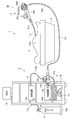
- FIG. 1 is a configuration diagram of a medical system according to the first embodiment.
- the medical system 1 is a system for inspecting or treating a subject 4 who is a patient on a bed 3 by using an endoscope system 2.
- the endoscope system 2 includes an endoscope 11, a system controller 12, a camera control unit 13, a light source device 14, an air supply device 15, a monitor 16, and a carbon dioxide gas cylinder 17.
- the system controller 12, the camera control unit 13, the light source device 14, the air supply device 15, and the monitor 16 are mounted on the cart 18, which is a mounting table.
- the carbon dioxide gas cylinder 17 is placed on the extension portion 18a extending from the cart 18.
- the carbon dioxide gas cylinder 17 is connected to the air supply device 15 by a connecting tube 17a.
- the endoscope 11 is provided at an elongated insertion portion 21, an operation portion 22 connected to the base end of the insertion portion 21, a universal cable 23 extending from the operation portion 22, and a tip portion of the universal cable 23. It has a connector 24.
- the connector 24 has a cable 24a connected to the camera control unit 13 and an air supply tube 24b connected to the air supply device 15.
- An observation window and an illumination window are provided at the tip of the insertion portion 21 of the endoscope 11.
- An image sensor such as a CMOS image sensor is provided behind the observation window.
- the light from the subject incident through the observation window is imaged on the image pickup surface of the image pickup device.
- the image pickup element photoelectrically converts the image in the subject imaged on the image pickup surface and outputs an image pickup signal.
- the image pickup signal is supplied to the camera control unit 13 by a signal line inserted into the insertion unit 21, the operation unit 22, the universal cable 23, and the cable 24a.
- the camera control unit 13 generates an endoscopic image based on the received imaging signal and outputs it to the monitor 16.
- a tip surface of an elongated light guide (not shown) is arranged.
- the light guide is inserted into the insertion unit 21, the operation unit 22, and the universal cable 23.
- the base end surface of the elongated light guide is arranged in the vicinity of the light source in the light source device 14 via the connector 24. Therefore, the light from the light source of the light source device 14 is emitted from the tip of the insertion portion 21 through the light guide to illuminate the inside of the subject.
- the reflected light of the illumination light is received by the image sensor. The surgeon can see the endoscopic image displayed on the monitor 16 and perform a desired examination or treatment.
- the system controller 12 controls the entire operation of the endoscope system 2 and various connected devices such as the camera control unit 13.
- the system controller 12 is connected to the camera control unit 13 by a signal cable (not shown).
- the camera control unit 13 is connected to the monitor 16 by a cable (not shown).
- the camera control unit 13 generates an endoscopic image and outputs an image signal of the endoscopic image to the monitor 16.
- the system controller 12 is connected to the light source device 14 and the air supply device 15 by a plurality of signal lines described later.
- the light source device 14 includes an air pump 14a, and air from the air pump 14a can be supplied to the air supply channel 23a in the universal cable 23 through an air flow path 24c (indicated by a dotted line) provided in the connector 24. It has become.
- the light source device 14 constitutes an air supply device for supplying air.
- the air supply device 15 discharges the carbon dioxide gas of the carbon dioxide gas cylinder 17 to the air supply tube 24b.
- the carbon dioxide gas from the air supply device 15 is supplied to the connector 24 via the air supply tube 24b.
- a gas path is formed in the connector 24 to communicate the air supply tube 24b and the air supply channel 23a in the universal cable 23.
- the air supply channel 23a in the universal cable 23 communicates with the air supply passage 21a in the insertion unit 21 through the operation unit 22.
- a liquid feeding path (not shown) is provided in the insertion portion 21.
- the tip of the air supply passage 21a is connected to the liquid supply passage, and one air supply liquid supply pipe line is formed at the tip of the insertion portion 21.
- the tip of the air supply / liquid supply line is connected to the nozzle at the tip of the insertion portion 21, and gas and liquid can be discharged from the nozzle opening 21b.
- the operation unit 22 is provided with an air supply / water supply button 22c and a suction button 22d.
- an air supply path for gas in the operation unit 22 is formed, and air from the light source device 14 or carbon dioxide gas from the air supply device 15 is sent. It can be supplied to the air passage 21a.
- the cylinder provided in the operation unit 22 is formed with an opening through which air or carbon dioxide gas flows.
- the gas / water supply button 22e may be connected instead of the air / water supply button 22c.
- the gas / water supply button 22e can be pressed in two steps. When the gas / water supply button 22e is not pressed, the gas stops at the inlet of the gas / water supply button 22e. When the gas / water supply button 22e is pressed one step, gas is sent, and when the gas / water supply button 22e is further pressed and pressed up to the second step, water is sent.
- the endoscope system 2 has an air supply device 15 for supplying carbon dioxide gas and a light source device 14 which is an air supply device for supplying air, and is provided in the endoscope 11.
- a light source device 14 which is an air supply device for supplying air
- the air supply / water supply button 22c which is a predetermined operation member, is operated, carbon dioxide gas or air gas is output from the tip of the endoscope 11. Therefore, the operator can send gas into the body cavity of the subject and secure the field of view of the endoscope by operating the air supply / water supply button 22c.
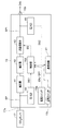
- FIG. 2 is a block diagram showing a connection relationship of signal lines between the system controller 12 constituting the endoscope system 1, the light source device 14, and the air supply device 15.
- the system controller 12 and the air supply device 15 are connected by a communication line 31.
- the system controller 12 and the light source device 14 are connected by a communication line 32.
- the light source device 14 and the air supply device 15 are connected by a communication line 33.
- the communication network 34 is composed of the communication lines 31, 32, 33.
- the communication network 34 is composed of communication lines 31, 32, and 33 formed in a ring shape, but may be another type of network such as a bus shape.
- the system controller 12, the light source device 14, and the air supply device 15 can communicate with each other via the communication network 34.
- the system controller 12 includes a control unit 12A, a storage device 12B, a setting unit 12C, and a communication circuit 35. Communication lines 31 and 32 are connected to the communication circuit 35. As described above, the system controller 12 includes various circuits, devices, and the like for controlling the entire endoscope system 1, but is omitted in FIG.
- the storage device 12B includes a program storage area 12p for storing various programs and a data storage area 12d for storing various data.
- the program storage area 12p includes a stop control program 12x that controls the stop of the air pump 14a of the light source device 14, which will be described later.
- the data storage area 12d includes data having a threshold value TH, which will be described later.
- the threshold value TH can be changed by the setting unit 12C. That is, the setting unit 12C constitutes a threshold value setting unit that sets a predetermined threshold value TH for the gas state.
- the setting unit 12C is, for example, a setting display device including a touch panel device and a display device.
- the control unit 12A can communicate with the light source device 14 and the air supply device 15 via the communication circuit 35. Therefore, the control unit 12A can receive various signals from the light source device 14 and the air supply device 15 and transmit control signals to the light source device 14 and the air supply device 15.
- the light source device 14 includes a control unit 14A, a communication circuit 36, and an air pump 14a.
- the light source device 14 includes various devices such as a light source and a filter, but is omitted in FIG.
- the power switch 14b When the power switch 14b is turned on, the light source device 14 turns on the air pump 14a and operates it. As a result, air is sent to the air supply channel 23a. In this state, when the operator closes the hole of the air supply / water supply button 22c, air is discharged from the nozzle opening 21b at the tip of the insertion portion 21.
- the light source device 14 has an on / off switch for turning on / off the air pump 14a separately from the power switch 14b, the on / off switch is turned on after the power switch 14b is turned on.
- the air pump 14a When set to, the air pump 14a is turned on.
- the control unit 14A can communicate with the system controller 12 and the air supply device 15 via the communication circuit 36.
- the air supply device 15 includes a control unit 15A and a communication circuit 37.
- the air supply device 15 includes various devices such as a decompressor and a sensor as described later, but is not shown in FIG.
- the control unit 15A can communicate with the system controller 12 and the light source device 14 via the communication circuit 37.
- the control unit 15A outputs a control signal SS to the flow rate adjusting valve 43 that supplies carbon dioxide gas, and transmits the detection signal DS of the sensor that detects the state of carbon dioxide gas to the system controller 12 via the communication circuit 37. Send in real time.
- the control unit 12A of the system controller 12 can generate a control signal for controlling the operation of the air pump 14a based on the received detection signal DS and transmit it to the light source device 14.
- Each control unit 12A, 14A, 15A includes a processor.
- the processor includes a central processing unit (CPU), a ROM, a RAM, and the like, and realizes various functions by reading a program stored in the ROM and the storage device 12B, expanding the program into the RAM, and executing the program.
- the processor may be composed of a semiconductor device such as an FPGA (Field Programmable Gate Array) or a circuit such as an electronic circuit.
- FIG. 3 is a block diagram showing the configuration of the air supply device 15.
- the air supply device 15 has a pipeline GP to which carbon dioxide gas from the carbon dioxide gas cylinder 17 is supplied.
- the pipeline GP communicates with the connecting tube 17a and the air supply tube 24b, and supplies the carbon dioxide gas from the carbon dioxide gas cylinder 17 to the air supply tube 24b connected to the air supply port 15b.
- the pipeline GP is provided with two decompressors 41 and 42 and a flow rate adjusting valve 43 in this order from the connection tube 17a side. The gas decompressed by the two decompressors 41 and 42 is supplied to the flow rate adjusting valve 43.
- a pressure gauge 44 is provided in the pipeline GP between the carbon dioxide gas cylinder 17 and the decompressor 41.
- the pressure gauge 44 detects the pressure of carbon dioxide gas in the carbon dioxide gas cylinder 17, and outputs the detected pressure detection signal DS1 to the control unit 15A.
- a pressure gauge 45 is provided between the flow rate adjusting valve 43 and the air supply tube 24b. That is, the pressure gauge 45, which is a gas state detection unit, is provided after the flow rate adjusting valve 43 for adjusting the flow rate of carbon dioxide gas in the air supply device 15.
- the pressure gauge 45 detects the pressure in the pipeline GP1 between the flow rate adjusting valve 43 and the air supply tube 24b, and outputs the detected pressure detection signal DS2 to the control unit 15A.
- the pressure gauge 45 is provided inside the air supply device 15 and constitutes a gas state detection unit that detects the state of carbon dioxide, here the pressure.
- the air supply device 15 has a power switch 15a.
- the control unit 15A is connected to the pressure gauges 44 and 45 and the flow rate adjusting valve 43.
- the control unit 15A detects the on / off state of the power switch 15a.
- the control unit 15A controls the flow rate adjusting valve 43 based on the detection signal DS2 of the pressure gauge 45 to supply carbon dioxide gas from the carbon dioxide gas cylinder 17 to the air supply tube 24b. .. Therefore, carbon dioxide gas is supplied from the air supply device 15 to the air supply tube 24b.
- the air supply device 15 may have an air supply switch 15c in addition to the power supply switch 15a.
- carbon dioxide gas is not supplied from the air supply device 15 to the air supply tube 24b only when the power switch 15a is turned on, and when the air supply switch 15c is further turned on, the control unit 15A
- the flow rate adjusting valve 43 is opened, and carbon dioxide gas is supplied from the air supply device 15 to the air supply tube 24b.
- the surgeon turns on the power switch of each device to be used before conducting an inspection.
- the surgeon does not turn on the power switch 15a of the air supply device 15 when sending air into the body cavity.
- the surgeon turns on the power switch 15a when he wants to send carbon dioxide gas into the body cavity instead of sending air into the body cavity.
- FIG. 4 is a flowchart showing an example of the flow of stop control of the air pump in the control unit 12A.
- the control unit 12A executes the stop control program 12x when the power switch 15a of the air supply device 15 is turned on.
- the control unit 12A detects the state (step (hereinafter abbreviated as S) 1).
- the state detection here is to detect the pressure P in the pipeline GP1.
- S1 is to receive the pressure data of the pressure value detected by the pressure gauge 45 from the air supply device 15.
- the control unit 12A determines whether to stop the air pump 14a after S1 (S2).
- the determination of whether to stop the air pump 14a is, here, determining whether the pressure P in the pipeline GP1 exceeds a predetermined threshold value TH1.
- the operator inputs the threshold value TH1 from the setting unit 12C in advance, stores it in the data storage area of the storage device 12B, and sets it.
- the flow rate adjusting valve 43 opens, so that the pressure P in the pipeline GP1 on the downstream side of the flow rate adjusting valve 43 of the pipeline GP rises.
- FIG. 5 is a graph showing the state of the power switch 15a of the air supply device 15, the state of the flow rate adjusting valve 43, and the change in the pressure detected by the pressure gauge 45.
- the horizontal axis of FIG. 5 indicates the passage of time.
- the power switch 15a is turned on at time t1
- the flow rate adjusting valve 43 is turned on and opened by the control unit 15A.
- the pressure in the pipeline GP1 rises.
- the pressure P detected by the pressure gauge 45 rises after time t1.
- the control unit 15A of the air supply device 15 transmits the detection value data of the detection signal DS2 to the system controller 12 in real time via the communication circuit 37. Therefore, the control unit 12A of the system controller 12 constantly monitors the received detection value data. Therefore, in S2, the control unit 15A determines whether the pressure P in the pipeline GP1 exceeds the predetermined threshold value TH1 based on the received detection value data.
- the control unit 12A instructs the air pump 14a to stop when the pressure P detected by the pressure gauge 45 exceeds the threshold value TH1 (S3). That is, the control unit 12A transmits an operation stop command for stopping the operation of the air pump 14a to the light source device 14.
- the pressure P in the pipeline GP1 exceeds a predetermined threshold value TH1 at the timing of time t2. Since the pressure P exceeds the predetermined threshold value TH1, the control unit 12A transmits an operation stop command for stopping the operation of the air pump 14a from the communication circuit 35 to the light source device 14 via the communication line 32.
- control unit 14A of the light source device 14 When the control unit 14A of the light source device 14 receives the operation stop command, it outputs an off signal to stop the operation of the air pump 14a to the air pump 14a. As described above, when the control unit 12A determines that the state of carbon dioxide gas detected by the pressure gauge 45, here the pressure, exceeds a predetermined threshold value TH1, the air pump 14a constituting the air supply device sends air. Control to stop.
- the control unit 12A When the air supply device 15 has the air supply switch 15c, the control unit 12A causes the control unit 12A to turn on the air supply switch 15c and when the pressure P detected by the pressure gauge 45 exceeds the threshold value TH1.
- An operation stop command for stopping the operation of the air pump 14a may be transmitted to the light source device 14.
- the light source device 14 Upon receiving the operation stop command, the light source device 14 stops the operation of the air pump 14a. That is, the control unit 12A controls to stop the air supply by the air pump 14a when the pressure in the state of carbon dioxide gas exceeds a predetermined threshold value TH1 and the air supply switch 15c of the air supply device 15 is on. I do.
- the control unit 14A stops the operation of the air pump 14a. If the air pump 14a is not operating when the operation stop command is received, the control unit 14A does nothing.
- the control unit 14A sets the operation prohibited state in which the air pump 14a is not operated even if the on / off switch is subsequently turned on. May be good. That is, the light source device 14 is in a state of not accepting the on / off switch. For example, the light source device 14 internally sets flag information indicating an operation prohibited state.
- the operator can change the air pump 14a from the disabled state to the operable state in case the blood carbon dioxide gas concentration of the patient rises or the like. , The operator may be made to confirm that the air pump 14a is operated.
- FIG. 6 is a graph showing the state of the power supply switch 15a of the air supply device 15, the state of the air supply switch 15c, the state of the flow rate adjusting valve 43, and the change in the pressure detected by the pressure gauge 45.
- the horizontal axis of FIG. 6 indicates the passage of time.
- the control unit 12A can determine that the air supply switch 15c of the air supply device 15 has been turned on by communicating with the air supply device 15 and acquiring the state information of the air supply switch 15c by communication.
- control unit 12A executes the process of stopping the operation of the air pump 14a at the timing of the time t2 (or t13) when the pressure P exceeds the predetermined threshold value TH1.
- control unit 12A of the system controller 12 receives the detection signal of the pressure gauge 45 from the air supply device 15 and transmits an operation stop command to stop the operation of the air pump 14a to the light source device 14.
- the control unit 15A of the air supply device 15 may directly transmit the operation stop command to the light source device 14.
- control unit 14A of the light source device 14 receives the detection value data of the pressure gauge 45 from the air supply device 15, determines whether the threshold value TH1 has been exceeded, and stops the operation of the air pump 14a. Good.
- the transmission processing of the pressure detection value data detected by the pressure gauge 45 in the air supply device 15 is executed by software processing in the control unit 15A or by a hardware circuit.
- the pressure monitoring process of the pressure gauge 45 in the system controller 12 and the operation stop command transmission process of the air pump 14a are also executed by the software process or the hardware circuit in the control unit 15A.
- the power switch 15a when the power switch 15a is turned on and the pressure P of the pressure gauge 45 exceeds a predetermined threshold value TH1 in order for the operator to use carbon dioxide gas for air supply into the body cavity, the light source device 14 The operation of the air pump 14a is stopped. Therefore, the amount of gas supplied into the body cavity does not become too large.
- the pressure in the pipeline GP1 of the pipeline GP is increased by the carbon dioxide gas from the air supply device 15, but in the unlikely event that sufficient gas does not remain in the carbon dioxide gas cylinder 17, the gas in the carbon dioxide gas cylinder 17 When the valve provided at the discharge port is closed, the pressure of the pressure gauge 45 does not rise properly.
- FIG. 7 is a graph showing the state of the power switch 15a of the air supply device 15, the state of the flow rate adjusting valve 43, the state of the gas supply / water supply button 22e, and the change in the pressure detected by the pressure gauge 45.
- the horizontal axis of FIG. 7 indicates the passage of time.
- the pressure in the pipeline GP1 rises.
- the pressure P detected by the pressure gauge 45 exceeds the threshold value TH1 at time t21.
- carbon dioxide gas is discharged from the nozzle opening 21b at the tip of the insertion portion 21.
- the pressure P in the pipeline GP1 drops below the threshold TH1.
- the pressure P is equal to or less than the threshold value TH1 at the timing of time t22.
- the control unit 12A when the pressure P detected by the pressure gauge 45 exceeds the threshold TH1 and the pressure P detected by the pressure gauge 45 subsequently becomes equal to or lower than the threshold TH1, the control unit 12A operates the air pump 14a.
- the operation stop command for stopping the operation is transmitted to the light source device 14.
- the present modification 1 also produces the same effect as that of the above-described embodiment.
- FIG. 8 is a graph showing the state of the power switch 15a of the air supply device 15, the state of the flow rate adjusting valve 43, the state of the air supply / water supply button 22c, and the change in the pressure detected by the pressure gauge 45.
- the horizontal axis of FIG. 8 indicates the passage of time.
- the control unit 12A When the pressure P becomes equal to or higher than the threshold value TH1b, the control unit 12A sends an operation stop command to stop the operation of the air pump 14a to the light source device 14, but the control unit 12A turns on the above-mentioned air supply switch 15c. If the pressure P detected by the pressure gauge 45 exceeds the threshold TH1 and then the pressure P detected by the pressure gauge 45 becomes equal to or lower than the threshold TH1 or exceeds the threshold TH1b, the control unit 12A May send an operation stop command to stop the operation of the air pump 14a.
- FIG. 9 shows the state of the power supply switch 15a of the air supply device 15, the state of the air supply switch 15c, the state of the flow rate adjusting valve 43, the state of the gas supply / water supply button 22d, and the change in the pressure detected by the pressure gauge 45. It is a graph which shows. The horizontal axis of FIG. 8 indicates the passage of time.
- the air supply switch 15c is turned on at time t32 after the power switch 15a is turned on at time t31
- the flow rate adjusting valve 43 is opened by the control unit 15A.
- the pressure P in the pipeline GP1 rises.
- the pressure P detected by the pressure gauge 45 rises after the time t32, and the pressure P in the pipeline GP1 exceeds the threshold value TH1.
- FIG. 10 shows the state of the power supply switch 15a of the air supply device 15, the state of the air supply switch 15c, the state of the flow rate adjusting valve 43, the state of the air supply / water supply button 22c, and the change in the pressure detected by the pressure gauge 45. It is a graph which shows. The horizontal axis of FIG. 10 indicates the passage of time.
- the air supply switch 15c is turned on at time t32'after the power switch 15a is turned on at time t31', the flow rate adjusting valve 43 is opened by the control unit 15A.
- the pressure P in the pipeline GP1 rises.
- the pressure P detected by the pressure gauge 45 rises after the time t32', and the pressure P in the pipeline GP1 exceeds the threshold value TH1a.
- an endoscopic system capable of reliably supplying carbon dioxide gas into the body cavity while reducing the burden on the operator is provided. be able to.
- the pressure in the pipeline GP1 downstream of the flow rate adjusting valve 43 is detected to stop the operation of the air pump 14a of the light source device 14, but in the second embodiment, the pipeline The operation of the air pump 14a of the light source device 14 is stopped by detecting the flow rate of the gas flowing through the GP.
- FIG. 11 is a block diagram showing the configuration of the air supply device 15 according to the second embodiment. Since the configuration of the air supply device 15 has almost the same configuration as the air supply device 15 of the first embodiment, the same components are designated by the same reference numerals and the description thereof is omitted, and only different components are used. explain.
- a flow meter 51 is provided in the pipeline GP1.
- the flow meter 51 detects the flow rate of the gas flowing in the pipeline GP1 and outputs the detection signal DS11 of the flow rate as the state of the detected gas to the control unit 15A. That is, the flow meter 51 is provided inside the air supply device 15 and constitutes a gas state detection unit that detects the state of carbon dioxide, here the flow rate.
- the flow meter 51 which is a gas state detection unit, is provided after the flow rate adjusting valve 43 for adjusting the flow rate of carbon dioxide gas in the air supply device 15.
- the detection signal DS11 is transmitted from the control unit 15A to the control unit 12A.
- the control unit 12A executes the stop control of the air pump shown in FIG. 4 based on the flow rate data received in real time.
- FIG. 12 is a graph showing the state of the power switch 15a of the air supply device 15, the state of the flow rate adjusting valve 43, the state of the gas / water supply button 22d, and the change in the flow rate detected by the flow meter 51.
- the horizontal axis of FIG. 12 shows the passage of time.
- the control unit 15A of the air supply device 15 transmits the detection value data of the detection signal DS11 to the system controller 12 in real time via the communication circuit 37. Therefore, the control unit 12A of the system controller 12 constantly monitors the received detection value data.
- the control unit 12A determines whether the flow rate Q of the carbon dioxide gas in the pipeline GP1 exceeds the predetermined threshold value TH2 based on the received detection value data.
- the threshold value TH2 is a flow rate value at a level at which it can be determined that the gas / water supply button 22d is pressed up to the first stage to start air supply and a certain amount of carbon dioxide gas is flowing.
- the operator inputs the threshold value TH2 from the setting unit 12C in advance, stores it in the data storage area of the storage device 12B, and sets it.
- the control unit 12A determines whether the flow rate Q of the carbon dioxide gas in the pipeline GP1 exceeds the predetermined threshold value TH2 based on the received detection value data, and determines that the flow rate Q of the carbon dioxide gas exceeds the predetermined threshold value TH2.
- an operation stop command for stopping the operation of the air pump 14a is transmitted to the light source device 14.
- the flow rate Q of carbon dioxide gas in the pipeline GP exceeds a predetermined threshold value TH2 at the timing of time t43.
- the light source device 14 stops the operation of the air pump 14a.
- the control unit 12A determines that the state of carbon dioxide gas detected by the flow meter 51, here the flow rate, exceeds a predetermined threshold value TH2
- the control unit 12A controls to stop the air supply by the air pump 14a.
- FIG. 13 is a graph showing the state of the power switch 15a of the air supply device 15, the state of the flow rate adjusting valve 43, the state of the air supply / water supply button 22c, and the change in the flow rate detected by the flow meter 51.
- the horizontal axis of FIG. 13 indicates the passage of time.
- the flow rate adjusting valve 43 After the flow rate adjusting valve 43 is opened, if the air supply / water supply button 22c is operated at time t42'to supply air, the flow rate of carbon dioxide gas flowing through the pipeline GP1 decreases. As shown in FIG. 13, the flow rate Q of the carbon dioxide gas detected by the flow meter 51 decreases from the threshold value TH2a after the time t42'.
- the control unit 15A of the air supply device 15 transmits the detection value data of the detection signal DS11 to the system controller 12 in real time via the communication circuit 37. Therefore, the control unit 12A of the system controller 12 constantly monitors the received detection value data.
- the control unit 12A determines whether the flow rate Q of the carbon dioxide gas in the pipeline GP1 exceeds the predetermined threshold value TH2a and then decreases below the threshold value TH2a based on the received detection value data.
- the threshold value TH2a is a flow rate value at a level at which it can be determined that insufflation is started and a certain amount of carbon dioxide gas flow is generated.
- the operator inputs the threshold value TH2a from the setting unit 12C in advance, stores it in the data storage area of the storage device 12B, and sets it.
- the control unit 12A determines whether the flow rate Q of the carbon dioxide gas in the pipeline GP1 exceeds the predetermined threshold value TH2a and then decreases from the threshold value TH2a based on the received detection value data, and the flow rate Q of the carbon dioxide gas is reduced.
- an operation stop command for stopping the operation of the air pump 14a is transmitted to the light source device 14.
- the flow rate Q of carbon dioxide gas in the pipeline GP exceeds a predetermined threshold value TH2a at the timing after time t41', and the flow rate Q of carbon dioxide gas in the pipeline GP is predetermined at the timing after time t42'.
- the light source device 14 stops the operation of the air pump 14a.
- the control unit 12A determines that the gas state detected by the flow meter 51, in this case, the flow rate, exceeds the predetermined threshold value TH2a and then falls below the predetermined threshold value TH2a
- the air pump 14a determines that the gas state is lower than the predetermined threshold value TH2a. Controls to stop the air supply.
- the control unit 14A Stops the operation of the air pump 14a. If the air pump 14a is not operating when the operation stop command is received, the control unit 14A does nothing.
- the control unit 14A if the air pump 14a is not operating when the operation stop command is received, the control unit 14A is then turned on and off.
- the operation prohibition state may be set so that the air pump 14a is not operated. That is, the light source device 14 is in a state of not accepting the on / off switch. Then, when the light source device 14 is in the inoperable state, the operator can change the air pump 14a from the inoperable state to the operable state in case the blood carbon dioxide gas concentration of the patient rises or the like. As described above, the operator may be asked to confirm that the air pump 14a is operated.
- an endoscopic system capable of reliably supplying carbon dioxide gas into the body cavity while reducing the burden on the operator is provided. be able to.
- control unit 12A receives the detection signal of the flow meter 51 from the air supply device 15 and transmits a stop signal for stopping the operation of the air pump 14a to the light source device 14, but the air is supplied.
- the control unit 15A of the device 15 may directly transmit the stop signal to the light source device 14.
- control unit 14A of the light source device 14 receives the detection value data of the flow meter 51 from the air supply device 15, determines whether the threshold value TH2 has been exceeded, and stops the operation of the air pump 14a. Good.
- the air supply / water supply button 22c is operated, and carbon dioxide gas actually flows. It is detected that the flow rate Q of carbon dioxide gas exceeds the actual predetermined threshold value TH2. If the valve of the carbon dioxide gas cylinder 17 is closed or the remaining amount of the carbon dioxide gas cylinder 17 is low, the carbon dioxide gas does not flow into the pipeline GP1. In that case, since the air pump 14a is not stopped, the operator can continue the inspection and the like without hindering the securing of the visual field.
- the control unit 12A in the control unit 12A, the power switch 15a or the air supply switch 15c described above is turned on, and the flow rate Q detected by the flow meter 51.
- the control unit 12A may transmit an operation stop command for stopping the operation of the air pump 14a. That is, the control unit 12A stops the air supply by the air pump 14a when the carbon dioxide gas state, in which the flow rate exceeds a predetermined threshold value TH2, and the air supply switch 15c of the air supply device 15 is on. Take control.
- the control unit 12A can determine that the power switch 15a or the air supply switch 15c of the air supply device 15 is turned on by communicating with the air supply device 15 and determining whether or not communication is possible.
- the control unit 12A can determine that the air supply switch 15c of the air supply device 15 is turned on by communicating with the air supply device 15 and acquiring the state information of the air supply switch 15c by communication.
- the pressure in the pipeline GP1 downstream of the flow rate adjusting valve 43 is detected to stop the operation of the air pump 14a of the light source device 14, but in the third embodiment, the pipeline The operation of the air pump 14a of the light source device 14 is stopped by detecting the concentration of carbon dioxide gas flowing through the GP1.
- FIG. 14 is a block diagram showing the configuration of the air supply device 15 according to the third embodiment. Since the configuration of the air supply device 15 has almost the same configuration as the air supply device 15 of the first embodiment, the same components are designated by the same reference numerals and the description thereof is omitted, and only different components are used. explain.
- a carbon dioxide gas concentration meter 61 is provided in the pipeline GP1.
- the carbon dioxide concentration meter 61 detects the carbon dioxide concentration of the gas flowing in the pipeline GP1 and outputs the detection signal DS21 of the carbon dioxide concentration as the state of the gas detected to the control unit 15A to the control unit 15A. That is, the carbon dioxide gas concentration meter 61 is provided inside the air supply device 15 and constitutes a gas state detecting unit for detecting the gas state of carbon dioxide gas, here, the carbon dioxide gas concentration.
- the carbon dioxide concentration meter 61 which is a gas state detection unit, is provided after the flow rate adjusting valve 43 for adjusting the flow rate of carbon dioxide gas in the air supply device 15.
- the detection signal DS21 is transmitted from the control unit 15A to the control unit 12A.
- the control unit 12A executes the stop control of the air pump shown in FIG. 4 based on the carbon dioxide gas concentration data received in real time.
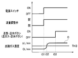
- FIG. 15 shows the state of the power switch 15a of the air supply device 15, the state of the flow rate adjusting valve 43, the state of the air supply / water supply button 22c (or the gas supply / water supply button 22d), and the carbon dioxide gas produced by the carbon dioxide concentration meter 61. It is a graph which shows the change of concentration. The horizontal axis of FIG. 15 indicates the passage of time. When the power switch 15a is turned on at time t51, the flow rate adjusting valve 43 is opened by the control unit 15A.
- the control unit 15A of the air supply device 15 transmits the detection value data of the detection signal DS21 to the system controller 12 in real time via the communication circuit 37. Therefore, the control unit 12A of the system controller 12 constantly monitors the received detection value data.
- the control unit 12A determines whether the carbon dioxide gas concentration D in the pipeline GP1 exceeds the predetermined threshold value TH3 based on the received detection value data value.
- the operator inputs the threshold value TH3 from the setting unit 12C in advance, stores it in the data storage area of the storage device 12B, and sets it.
- the control unit 12A determines whether the carbon dioxide concentration D in the pipeline GP1 exceeds a predetermined threshold value TH3 based on the received detection value data, and detects that the carbon dioxide gas concentration D exceeds a predetermined threshold value TH3. , Sends an operation stop command to stop the operation of the air pump 14a to the light source device 14.
- the carbon dioxide gas concentration D in the pipeline GP1 exceeds a predetermined threshold value TH3 at the timing of time t52.
- the air supply / water supply button 22c (or gas supply / water supply button 22d) is operated at the timing of time t53.
- the light source device 14 stops the operation of the air pump 14a.
- control unit 12A determines that the state of carbon dioxide gas detected by the carbon dioxide gas concentration meter 61, here the carbon dioxide gas concentration, exceeds a predetermined threshold value TH3, the control unit 12A stops the air supply by the air pump 14a. Take control.
- control unit 12A receives the detection signal of the carbon dioxide concentration meter 61 from the air supply device 15 and sends an operation stop command to stop the operation of the air pump 14a to the light source device 14.
- the control unit 15A of the air supply device 15 may directly transmit the operation stop command to the light source device 14.
- control unit 14A of the light source device 14 receives the detection value data of the carbon dioxide gas concentration meter 61 from the air supply device 15, determines whether the threshold value TH3 has been exceeded, and stops the operation of the air pump 14a. You may.
- the air supply / water supply button 22c (or the gas supply / water supply button 22d) is operated. , It is detected that the carbon dioxide gas actually flows and the carbon dioxide gas concentration D exceeds the actual predetermined threshold value TH3. If the valve of the carbon dioxide gas cylinder 17 is closed or the remaining amount of the carbon dioxide gas cylinder 17 is low, the carbon dioxide gas does not flow into the pipeline GP1 and the carbon dioxide gas concentration D does not increase. In that case, since the air pump 14a is not stopped, the operator can continue the inspection and the like without hindering the securing of the visual field.
- the control unit 12A has the power switch 15a or the air supply switch 15c described above turned on and detected by the carbon dioxide concentration meter 61.
- the control unit 12A may transmit an operation stop command for stopping the operation of the air pump 14a. That is, the control unit 12A sends air by the air pump 14a when the carbon dioxide gas state, in which the carbon dioxide gas concentration exceeds a predetermined threshold value TH3, and the air supply switch 15c of the air supply device 15 is on. Control to stop the qi.
- the control unit 12A can determine that the power switch 15a or the air supply switch 15c of the air supply device 15 is turned on by communicating with the air supply device 15 and determining whether or not communication is possible.
- the control unit 12A can determine that the air supply switch 15c of the air supply device 15 is turned on by communicating with the air supply device 15 and acquiring the state information of the air supply switch 15c by communication.
- an endoscopic system capable of reliably supplying carbon dioxide gas into the body cavity while reducing the burden on the operator is provided. be able to.
- any one of the pressure, flow rate, and carbon dioxide concentration of carbon dioxide in the pipeline is detected by the detector, but the pressure and flow rate, pressure and carbon dioxide gas are detected.
- the air pump 14a of the light source device 14 is turned on. It may be stopped.
- the present invention is not limited to the above-described embodiment, and various modifications, modifications, and the like can be made without changing the gist of the present invention.
Landscapes
- Life Sciences & Earth Sciences (AREA)
- Health & Medical Sciences (AREA)
- Surgery (AREA)
- Engineering & Computer Science (AREA)
- Biophysics (AREA)
- Biomedical Technology (AREA)
- Nuclear Medicine, Radiotherapy & Molecular Imaging (AREA)
- Optics & Photonics (AREA)
- Pathology (AREA)
- Radiology & Medical Imaging (AREA)
- Veterinary Medicine (AREA)
- Physics & Mathematics (AREA)
- Heart & Thoracic Surgery (AREA)
- Medical Informatics (AREA)
- Molecular Biology (AREA)
- Animal Behavior & Ethology (AREA)
- General Health & Medical Sciences (AREA)
- Public Health (AREA)
- Signal Processing (AREA)
- Endoscopes (AREA)
Abstract
La présente invention concerne un système d'endoscope (1) comprenant : un dispositif de distribution de gaz (15) pour distribuer du dioxyde de carbone gazeux ; et un dispositif de source de lumière (14) sur lequel est montée une pompe à air (14a) pour fournir de l'air. Lorsqu'un bouton de distribution de gaz/eau (22c) disposé sur un endoscope (11) est actionné, soit du dioxyde de carbone gazeux soit de l'air est distribué à partir de l'extrémité distale de l'endoscope (11). Le système d'endoscope (1) comprend : une jauge de pression (45) qui est disposée à l'intérieur du dispositif de distribution d'air (15) et détecte la pression du dioxyde de carbone gazeux ; et une unité de commande (12A) qui, lorsqu'il est déterminé que la pression du gaz détectée par la jauge de pression (45) dépasse une valeur seuil prédéterminée TH, réalise une commande pour arrêter la distribution d'air par la pompe à air (14a).
Priority Applications (5)
| Application Number | Priority Date | Filing Date | Title |
|---|---|---|---|
| PCT/JP2019/016359 WO2020213063A1 (fr) | 2019-04-16 | 2019-04-16 | Système d'endoscope |
| CN201980095426.0A CN113677253B (zh) | 2019-04-16 | 2019-04-16 | 内窥镜系统 |
| JP2021514691A JP7150982B2 (ja) | 2019-04-16 | 2019-04-16 | 内視鏡システム、制御装置及び送気制御方法 |
| US17/500,469 US12349870B2 (en) | 2019-04-16 | 2021-10-13 | Endoscope system, control apparatus, and gas feeding control method |
| US19/234,814 US20250302285A1 (en) | 2019-04-16 | 2025-06-11 | Endoscope system, control apparatus, and gas feeding control method |
Applications Claiming Priority (1)
| Application Number | Priority Date | Filing Date | Title |
|---|---|---|---|
| PCT/JP2019/016359 WO2020213063A1 (fr) | 2019-04-16 | 2019-04-16 | Système d'endoscope |
Related Child Applications (1)
| Application Number | Title | Priority Date | Filing Date |
|---|---|---|---|
| US17/500,469 Continuation US12349870B2 (en) | 2019-04-16 | 2021-10-13 | Endoscope system, control apparatus, and gas feeding control method |
Publications (1)
| Publication Number | Publication Date |
|---|---|
| WO2020213063A1 true WO2020213063A1 (fr) | 2020-10-22 |
Family
ID=72838159
Family Applications (1)
| Application Number | Title | Priority Date | Filing Date |
|---|---|---|---|
| PCT/JP2019/016359 Ceased WO2020213063A1 (fr) | 2019-04-16 | 2019-04-16 | Système d'endoscope |
Country Status (4)
| Country | Link |
|---|---|
| US (2) | US12349870B2 (fr) |
| JP (1) | JP7150982B2 (fr) |
| CN (1) | CN113677253B (fr) |
| WO (1) | WO2020213063A1 (fr) |
Families Citing this family (2)
| Publication number | Priority date | Publication date | Assignee | Title |
|---|---|---|---|---|
| CN120753567A (zh) * | 2025-09-10 | 2025-10-10 | 杭州灵眸医疗科技有限公司 | 内窥镜冷光源的气体切换方法、系统、设备、介质及产品 |
| CN120982965A (zh) * | 2025-09-30 | 2025-11-21 | 青岛迈德康医疗科技有限公司 | 集成多模态功能的高频喷射视频喉镜及使用方法 |
Citations (3)
| Publication number | Priority date | Publication date | Assignee | Title |
|---|---|---|---|---|
| JP2011212134A (ja) * | 2010-03-31 | 2011-10-27 | Fujifilm Corp | 医療用送気システム |
| JP2011244937A (ja) * | 2010-05-25 | 2011-12-08 | Fujifilm Corp | 内視鏡システム |
| JP2012035060A (ja) * | 2010-07-14 | 2012-02-23 | Fujifilm Corp | 内視鏡の送気システム |
Family Cites Families (25)
| Publication number | Priority date | Publication date | Assignee | Title |
|---|---|---|---|---|
| JP3041220B2 (ja) * | 1995-07-28 | 2000-05-15 | オリンパス光学工業株式会社 | 気腹装置 |
| JP4526313B2 (ja) * | 2004-07-01 | 2010-08-18 | オリンパス株式会社 | 送気システム |
| JP2006026313A (ja) * | 2004-07-21 | 2006-02-02 | Olympus Corp | 送気システム |
| JP4716689B2 (ja) * | 2004-08-04 | 2011-07-06 | オリンパス株式会社 | 内視鏡システム |
| WO2006064713A1 (fr) * | 2004-12-15 | 2006-06-22 | Olympus Medical Systems Corp. | Dispositif d’alimentation en gaz, procede de commande de dispositif d’alimentation en gaz, systeme d’alimentation en gaz et systeme endoscopique |
| JP4373358B2 (ja) * | 2005-04-13 | 2009-11-25 | オリンパスメディカルシステムズ株式会社 | 送気装置の制御方法及び送気装置及び送気装置を有する内視鏡システム |
| JP2006167122A (ja) * | 2004-12-15 | 2006-06-29 | Olympus Corp | 送気システム |
| JP4885444B2 (ja) | 2004-12-17 | 2012-02-29 | オリンパス株式会社 | 送気装置 |
| US8152716B2 (en) * | 2005-08-18 | 2012-04-10 | Stryker Gi Ltd. | Versatile control system for supplying fluid medium to endoscope |
| JP5362636B2 (ja) * | 2010-03-31 | 2013-12-11 | 富士フイルム株式会社 | 医療用送気システム |
| JP5922533B2 (ja) * | 2012-09-06 | 2016-05-24 | 富士フイルム株式会社 | 送気システム |
| JP5650697B2 (ja) * | 2012-09-06 | 2015-01-07 | 富士フイルム株式会社 | 送気システム |
| JP5901500B2 (ja) * | 2012-11-12 | 2016-04-13 | オリンパス株式会社 | 送気システム |
| CN104812287A (zh) * | 2012-11-27 | 2015-07-29 | 富士胶片株式会社 | 送气系统 |
| JP6245864B2 (ja) * | 2013-07-02 | 2017-12-13 | オリンパス株式会社 | 気腹装置 |
| JP6077973B2 (ja) * | 2013-09-18 | 2017-02-08 | 富士フイルム株式会社 | 送気装置 |
| DE102014103941A1 (de) * | 2014-03-21 | 2015-09-24 | Storz Endoskop Produktions Gmbh | Insufflationssystem |
| JP6182100B2 (ja) * | 2014-04-09 | 2017-08-16 | 富士フイルム株式会社 | 送気システム及び送気装置 |
| JP6097246B2 (ja) * | 2014-04-09 | 2017-03-15 | 富士フイルム株式会社 | 送気システム及び送気装置 |
| AU2015350026B2 (en) * | 2014-11-19 | 2020-08-13 | Breethe, Inc. | Artificial lung system and its methods of use |
| JP6472078B2 (ja) * | 2015-04-01 | 2019-02-20 | オリンパス株式会社 | 内視鏡システム |
| JP6438837B2 (ja) * | 2015-05-11 | 2018-12-19 | オリンパス株式会社 | 気腹装置 |
| JP2017064317A (ja) * | 2015-10-02 | 2017-04-06 | オリンパス株式会社 | 排煙装置 |
| EP3466470B1 (fr) * | 2017-10-09 | 2021-08-04 | Leved | Régulateur de pression pour ballonnet de sonde d'intubation, et système de respiration comportant un tel régulateur |
| EP3782528B1 (fr) * | 2019-08-23 | 2023-04-19 | Chang Gul Hong | Dispositif d'alimentation en fluide pour endoscope |
-
2019
- 2019-04-16 WO PCT/JP2019/016359 patent/WO2020213063A1/fr not_active Ceased
- 2019-04-16 JP JP2021514691A patent/JP7150982B2/ja active Active
- 2019-04-16 CN CN201980095426.0A patent/CN113677253B/zh active Active
-
2021
- 2021-10-13 US US17/500,469 patent/US12349870B2/en active Active
-
2025
- 2025-06-11 US US19/234,814 patent/US20250302285A1/en active Pending
Patent Citations (3)
| Publication number | Priority date | Publication date | Assignee | Title |
|---|---|---|---|---|
| JP2011212134A (ja) * | 2010-03-31 | 2011-10-27 | Fujifilm Corp | 医療用送気システム |
| JP2011244937A (ja) * | 2010-05-25 | 2011-12-08 | Fujifilm Corp | 内視鏡システム |
| JP2012035060A (ja) * | 2010-07-14 | 2012-02-23 | Fujifilm Corp | 内視鏡の送気システム |
Also Published As
| Publication number | Publication date |
|---|---|
| CN113677253A (zh) | 2021-11-19 |
| JPWO2020213063A1 (ja) | 2021-12-23 |
| US12349870B2 (en) | 2025-07-08 |
| US20220031153A1 (en) | 2022-02-03 |
| CN113677253B (zh) | 2024-12-17 |
| JP7150982B2 (ja) | 2022-10-11 |
| US20250302285A1 (en) | 2025-10-02 |
Similar Documents
| Publication | Publication Date | Title |
|---|---|---|
| CN110799079B (zh) | 内窥镜和泄漏测试的通知方法 | |
| US20160106934A1 (en) | Insufflation apparatus | |
| US8231523B2 (en) | Endoscopic system equipped with gas supply apparatus | |
| US20250302285A1 (en) | Endoscope system, control apparatus, and gas feeding control method | |
| US9155455B2 (en) | Endoscope gas delivery system | |
| US20070244363A1 (en) | Gas supplying apparatus, control method of the same, gas supplying system, and endoscope system | |
| CN105813537B (zh) | 气腹装置 | |
| JP5362636B2 (ja) | 医療用送気システム | |
| US11089950B2 (en) | Endoscope apparatus, activation method, and video processor for determining an abnormality | |
| JP2015058120A (ja) | 送気装置 | |
| CN100542475C (zh) | 送气装置和内窥镜系统 | |
| JP2014113256A (ja) | 気腹システム | |
| JP6438836B2 (ja) | 気腹システム | |
| CN104812287A (zh) | 送气系统 | |
| JP6422394B2 (ja) | 気腹システム | |
| CN107106001A (zh) | 监测系统 | |
| JP4584007B2 (ja) | 送気装置及び送気装置を有する内視鏡システム | |
| JP2007075396A (ja) | 医療用送気装置 | |
| JP2003010105A (ja) | 内視鏡装置 | |
| KR101118705B1 (ko) | 내시경의 일회용 프로브 | |
| US12185920B2 (en) | Gas feeding apparatus, supply method and gas feeding system for stopping and reducing gas feeding based on set threshold | |
| US20250268614A1 (en) | System and method for detecting and preventing organ collapse during endoscopy | |
| JP2007075316A (ja) | 内視鏡用送気装置 | |
| WO2020070785A1 (fr) | Dispositif endoscopique, système d'alimentation en gaz endoscopique, procédé de commande, et programme | |
| KR20120100668A (ko) | 일회용 프로브를 이용하는 내시경 조작유닛 |
Legal Events
| Date | Code | Title | Description |
|---|---|---|---|
| 121 | Ep: the epo has been informed by wipo that ep was designated in this application |
Ref document number: 19924934 Country of ref document: EP Kind code of ref document: A1 |
|
| ENP | Entry into the national phase |
Ref document number: 2021514691 Country of ref document: JP Kind code of ref document: A |
|
| NENP | Non-entry into the national phase |
Ref country code: DE |
|
| 122 | Ep: pct application non-entry in european phase |
Ref document number: 19924934 Country of ref document: EP Kind code of ref document: A1 |