WO2020217376A1 - 静止誘導機器 - Google Patents
静止誘導機器 Download PDFInfo
- Publication number
- WO2020217376A1 WO2020217376A1 PCT/JP2019/017608 JP2019017608W WO2020217376A1 WO 2020217376 A1 WO2020217376 A1 WO 2020217376A1 JP 2019017608 W JP2019017608 W JP 2019017608W WO 2020217376 A1 WO2020217376 A1 WO 2020217376A1
- Authority
- WO
- WIPO (PCT)
- Prior art keywords
- plate
- shaped portion
- flow path
- hole portions
- insulating
- Prior art date
- Legal status (The legal status is an assumption and is not a legal conclusion. Google has not performed a legal analysis and makes no representation as to the accuracy of the status listed.)
- Ceased
Links
Images








Classifications
-
- H—ELECTRICITY
- H01—ELECTRIC ELEMENTS
- H01F—MAGNETS; INDUCTANCES; TRANSFORMERS; SELECTION OF MATERIALS FOR THEIR MAGNETIC PROPERTIES
- H01F27/00—Details of transformers or inductances, in general
- H01F27/08—Cooling; Ventilating
- H01F27/10—Liquid cooling
- H01F27/12—Oil cooling
- H01F27/125—Cooling by synthetic insulating and incombustible liquid
-
- H—ELECTRICITY
- H01—ELECTRIC ELEMENTS
- H01F—MAGNETS; INDUCTANCES; TRANSFORMERS; SELECTION OF MATERIALS FOR THEIR MAGNETIC PROPERTIES
- H01F27/00—Details of transformers or inductances, in general
- H01F27/28—Coils; Windings; Conductive connections
- H01F27/32—Insulating of coils, windings, or parts thereof
- H01F27/322—Insulating of coils, windings, or parts thereof the insulation forming channels for circulation of the fluid
-
- H—ELECTRICITY
- H01—ELECTRIC ELEMENTS
- H01F—MAGNETS; INDUCTANCES; TRANSFORMERS; SELECTION OF MATERIALS FOR THEIR MAGNETIC PROPERTIES
- H01F27/00—Details of transformers or inductances, in general
- H01F27/02—Casings
- H01F27/025—Constructional details relating to cooling
-
- H—ELECTRICITY
- H01—ELECTRIC ELEMENTS
- H01F—MAGNETS; INDUCTANCES; TRANSFORMERS; SELECTION OF MATERIALS FOR THEIR MAGNETIC PROPERTIES
- H01F27/00—Details of transformers or inductances, in general
- H01F27/08—Cooling; Ventilating
- H01F27/10—Liquid cooling
- H01F27/12—Oil cooling
-
- H—ELECTRICITY
- H01—ELECTRIC ELEMENTS
- H01F—MAGNETS; INDUCTANCES; TRANSFORMERS; SELECTION OF MATERIALS FOR THEIR MAGNETIC PROPERTIES
- H01F27/00—Details of transformers or inductances, in general
- H01F27/28—Coils; Windings; Conductive connections
- H01F27/30—Fastening or clamping coils, windings, or parts thereof together; Fastening or mounting coils or windings on core, casing, or other support
- H01F27/306—Fastening or mounting coils or windings on core, casing or other support
-
- H—ELECTRICITY
- H01—ELECTRIC ELEMENTS
- H01F—MAGNETS; INDUCTANCES; TRANSFORMERS; SELECTION OF MATERIALS FOR THEIR MAGNETIC PROPERTIES
- H01F27/00—Details of transformers or inductances, in general
- H01F27/28—Coils; Windings; Conductive connections
- H01F27/32—Insulating of coils, windings, or parts thereof
- H01F27/324—Insulation between coil and core, between different winding sections, around the coil; Other insulation structures
Definitions
- the present invention relates to a stationary induction device.
- Patent Document 1 Jitsukaisho 58-196814
- the high-voltage winding and the low-voltage winding are insulated by a flat plate-shaped interwinding insulating plate.
- An oil duct is formed between the high-pressure winding and the low-pressure winding by attaching an insulating piece to the surface of the flat plate-shaped insulating plate.
- These members are arranged in the tank and are filled with insulating oil.
- the insulating oil enters between the high pressure winding and the low pressure winding from one end of the winding, and receives the heat of the winding and is heated while passing between these windings.
- the insulating oil is sent out from the other end of the winding, is sent to the oil cooler by the oil pump through the pipe, and then cooled by the blower and returned to the tank.
- Insulation oil may flow between a plurality of insulating pieces attached to an insulating plate between a plurality of windings provided in a conventional static induction device.
- the plurality of insulating pieces are arranged one by one in consideration of the formed flow path. Therefore, the work of pasting a plurality of insulating pieces becomes complicated.
- the present invention has been made in view of the above problems, and an object of the present invention is to provide a stationary induction device capable of easily forming a flow path of insulating oil between a plurality of windings.
- the static induction device based on the present invention includes an iron core, a plurality of windings, a plurality of insulating plates, and a tank.
- Each of the plurality of windings is wound around the iron core with the iron core as the central axis.
- Each of the plurality of windings is coaxially arranged.
- Each of the plurality of insulating plates is located so as to be sandwiched between the windings adjacent to each other in a plurality of windings on a one-to-one basis.
- the tank houses an iron core, multiple windings and multiple insulating plates.
- the tank is filled with insulating oil.
- the tank is configured such that insulating oil flows in the tank in a first direction orthogonal to the central axis direction of the plurality of windings.
- Each of the plurality of insulating plates includes a first plate-shaped portion and a second plate-shaped portion adjacent to each other in the central axial direction.
- a plurality of first hole portions penetrating in the central axis direction are formed in the first plate-shaped portion.
- a plurality of second holes penetrating in the central axis direction are formed in the second plate-shaped portion.
- At least one of the first plate-shaped portion or the second plate-shaped portion has a first notch formed at one edge in the first direction and a second notch at the other edge in the first direction. The part is formed.
- one side and the other side of each of the plurality of insulating plates can be used.
- a flow path through which insulating oil can flow is constructed by communicating with each other.
- a flow path of insulating oil between the plurality of windings can be easily formed.
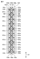
- FIG. 5 is an exploded perspective view showing a laminated structure of a plurality of windings and a plurality of insulating plates included in the stationary induction device according to the first embodiment of the present invention. It is a figure which shows the shape of the insulating plate in Embodiment 1 of this invention.
- FIG. 5 is a cross-sectional view of the insulating plate shown in FIG.
- FIG. 13 is a view of the insulating plate shown in FIG. 13 as viewed from the direction of the XV-XV line arrow. It is a figure which shows the shape of the 1st plate-like part of the insulating plate in Embodiment 3 of this invention.
- FIG. 18 is a view of the insulating plate shown in FIG. 18 as viewed from the direction of the XIX-XIX line arrow.
- FIG. 18 is a view of the insulating plate shown in FIG. 18 as viewed from the direction of the XX-XX line arrow.
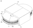
- FIG. 1 is a perspective view showing the appearance of the stationary guidance device according to the first embodiment of the present invention.
- FIG. 2 is a perspective view showing a part of the configuration of the stationary guidance device according to the first embodiment of the present invention.
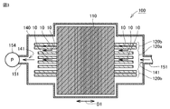
- FIG. 3 is a partial cross-sectional view of the rest guidance device shown in FIG. 1 as viewed from the direction of the arrow along line III-III.
- FIG. 4 is an exploded perspective view showing a laminated structure of a plurality of windings and a plurality of insulating plates included in the stationary induction device according to the first embodiment of the present invention.
- the rest induction device 100 is an in-vehicle transformer.
- the static induction device 100 according to the present embodiment is a so-called outer iron type transformer.
- the stationary induction device 100 includes an iron core 110, a plurality of windings 120, a plurality of insulating plates 130, and a tank 140.
- the plurality of insulating plates 130 are not shown.
- the iron core 110 includes a main landing gear portion 111 and a side landing gear portion 112.
- the side landing gear 112 is connected to the main landing gear 111.
- each of the plurality of windings 120 is wound around the iron core 110 with the iron core 110 as the central axis. Specifically, each of the plurality of windings 120 is wound around the main landing gear 111 while being passed between the main landing gear 111 and the side landing gear 112. In this way, each of the plurality of windings 120 is coaxially arranged. In the present embodiment, each of the plurality of windings 120 is a flat winding.
- each of the plurality of windings 120 includes a plurality of high-pressure windings 120a and a plurality of low-pressure windings 120b.
- the plurality of high-pressure windings 120a are located sandwiched between the pair of the plurality of low-pressure windings 120b.
- each of the plurality of insulating plates 130 is located so as to be sandwiched between the windings 120 adjacent to each other on a one-to-one basis in the plurality of windings 120.
- the configuration of each of the plurality of insulating plates 130 will be described later.
- the tank 140 houses an iron core 110, a plurality of windings 120, and a plurality of insulating plates 130.
- the tank 140 is filled with insulating oil.
- the tank 140 is configured such that insulating oil flows in the tank 140 in a first direction D1 orthogonal to the central axis direction of the plurality of windings 120.
- the stationary guidance device 100 further includes a circulation pipe 151.
- the circulation pipe 151 connects two connecting portions 141 located at both ends of the tank 140 in the first direction D1.
- a pump 154 is provided in the circulation pipe 151. When the pump 154 is operated, the insulating oil circulates in the tank 140 and the circulation pipe 151.
- a cooling container 153 is further connected to the circulation pipe 151.
- the cooling container 153 is cooled from the outside by the wind sent from the electric blower 152. As a result, the insulating oil that has flowed into the cooling container 153 is cooled and then flows into the circulation pipe 151 again.
- the insulating oil that has flowed in from one of the connecting portions 141 flows through the insulating oil flow path 10 formed between the plurality of windings 120 that are adjacent to each other. As a result, the heat of the winding 120 adjacent to the flow path 10 is transferred to the insulating oil. As a result, the plurality of windings 120 are cooled.
- the flow path 10 is composed of a plurality of insulating plates 130.
- the flow path 10 in the present embodiment will be described together with the configurations of the plurality of insulating plates 130.
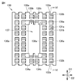
- FIG. 5 is a diagram showing the shape of the insulating plate according to the first embodiment of the present invention.
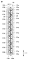
- FIG. 6 is a cross-sectional view of the insulating plate shown in FIG. 5 as viewed from the direction of the arrow along the VI-VI line.
- FIG. 7 is a diagram showing the shape of the first plate-shaped portion of the insulating plate according to the first embodiment of the present invention.
- FIG. 8 is a diagram showing the shape of the second plate-shaped portion of the insulating plate according to the first embodiment of the present invention.
- a plurality of windings 120 adjacent to the insulating plate 130 are shown together.
- each of the plurality of insulating plates 130 has a rectangular outer shape when viewed from the central axis direction of the plurality of windings 120.
- Each of the plurality of insulating plates 130 is located so that the longitudinal direction of each of the plurality of insulating plates 130 is along the first direction D1. That is, the lateral direction of each of the plurality of insulating plates 130 is located along the second direction D2 orthogonal to both the central axis direction and the first direction D1.
- Each of the plurality of insulating plates 130 is formed with an opening 137 penetrating in the central axis direction.
- the iron core 110 shown in FIG. 2 is located in the opening 137.
- the main landing gear 111 is located in the opening 137.
- each of the plurality of insulating plates 130 includes a first plate-shaped portion 130a and a second plate-shaped portion 130b that are adjacent to each other in the central axis direction.
- each of the plurality of insulating plates 130 is composed of a first plate-shaped portion 130a and a second plate-shaped portion 130b.
- Each of the first plate-shaped portion 130a and the second plate-shaped portion 130b is made of an insulating material, for example, an insulating paper such as a press board or an insulating material such as polyamide.
- first hole portions 131a penetrating in the central axis direction are formed in the first plate-shaped portion 130a.
- the first hole portion 131a has a rectangular outer shape, and specifically has a square outer shape.
- the first plate-shaped portion 130a is formed with a first notch portion 132a at one end edge 134a of the first direction D1. Specifically, a plurality of first notch portions 132a are formed in the first plate-shaped portion 130a. In the present embodiment, the angles formed by the corners of the plurality of first notches 132a of the first plate-shaped portion 130a are right angles.
- a second notch portion 133a is formed at the other end edge 135a in the first direction D1. Specifically, a plurality of second notch portions 133a are formed in the first plate-shaped portion 130a. In the present embodiment, the angles formed by the respective corners of the plurality of second notches 133a of the first plate-shaped portion 130a are right angles.
- the lateral edge 136a located on both sides of the first plate-shaped portion 130a in the second direction D2 has a linear outer shape along the first direction D1.
- a plurality of inner peripheral notches 139a are formed on the inner peripheral edge 138a of the first plate-shaped portion 130a.
- the plurality of inner peripheral notch portions 139a are located so as to be sandwiched between the plurality of first hole portions 131a in the first direction D1.
- each of the first hole portion 131a, the first plate-shaped portion 130a, the first notch portion 132a, and the second notch portion 133a when viewed from the central axis direction is not particularly limited.
- the outer shape of each of the first hole 131a, the first plate-shaped 130a, the first notch 132a, and the second notch 133a when viewed from the central axis direction is caused by the shape of the insulating oil flow path 10. It can be changed as appropriate to reduce the pressure loss.
- a plurality of second hole portions 131b penetrating in the central axis direction are formed in the second plate-shaped portion 130b.
- the second hole portion 131b has a rectangular outer shape, and specifically has a square outer shape.
- the second plate-shaped portion 130b is formed with a first notch portion 132b at one end edge 134b of the first direction D1. Specifically, a plurality of first notch portions 132b are formed in the second plate-shaped portion 130b. In the present embodiment, the angles formed by the corners of the plurality of first notches 132b of the second plate-shaped portion 130b are right angles.
- a second notch portion 133b is formed at the other end edge 135b in the first direction D1. Specifically, a plurality of second notch portions 133b are formed in the second plate-shaped portion 130b. In the present embodiment, the angles formed by the corners of the plurality of second notches 133b of the second plate-shaped portion 130b are right angles.
- the lateral edge 136b located on both sides of the second plate-shaped portion 130b in the second direction D2 has a linear outer shape along the first direction D1.
- a plurality of inner peripheral notches 139b are formed on the inner peripheral edge 138b of the second plate-shaped portion 130b.
- each of the second hole portion 131b, the first notch portion 132b of the second plate-shaped portion 130b, and the second notch portion 133b when viewed from the central axis direction is not particularly limited.
- the outer shape of each of the second hole portion 131b, the first notch portion 132b, and the second notch portion 133b of the second plate-shaped portion 130b when viewed from the central axis direction is caused by the shape of the insulating oil flow path 10. It can be changed as appropriate to reduce the pressure loss.
- At least one of the first plate-shaped portion 130a or the second plate-shaped portion 130b is formed with the first cutout portions 132a, 132b at one end edge 134a, 134b of the first direction D1.
- Second notches 133a, 133b are formed at the other edge 135a, 135b in the first direction D1.
- a flow path 10 through which insulating oil can flow is configured by communicating one side and the other side of each of the plurality of insulating plates 130 with each other.
- the flow path 10 when viewed from the central axis direction, includes a linear flow path 11 formed along the first direction D1.
- the flow path 10 includes a plurality of linear flow paths 11 when viewed from the central axis direction.
- the first hole portion 131a located on the onemost end edge 134a side overlaps with the first notch portion 132b.
- Each of the plurality of second hole portions 131b overlaps with both of the two first hole portions 131a adjacent to each other in the first direction D1.
- the first hole 131a located on the most 135a side overlaps the second notch 133b. In this way, the linear flow path 11 is configured.
- each of the plurality of inner peripheral notch portions 139a is two first hole portions of the plurality of first hole portions 131a arranged along the first direction D1. It may be located between 131a.
- the plurality of first hole portions 131a, the plurality of second hole portions 131b, the first notch portions 132a, 132b, the second notch portions 133a, 133b, and the plurality of 139a overlap each other.
- the flow path 10 is configured in the first direction D1.
- the plurality of first hole portions 131a, the plurality of second hole portions 131b, the first notch portions 132a, 132b and the second notch portion 133a , 133b are overlapped with each other, so that in the first direction D1, one side and the other side of each of the plurality of insulating plates 130 are communicated with each other to form a flow path 10 through which insulating oil can flow. There is.
- the flow path 10 includes a linear flow path 11 formed along the first direction D1 when viewed from the central axis direction.
- the insulating oil flowing through the linear flow path 11 has the winding 120 adjacent to the first plate-shaped portion 130a and the winding 120 adjacent to the second plate-shaped portion 130b. It can be cooled alternately. As a result, the plurality of windings 120 can be efficiently cooled as a whole.
- Embodiment 2 the rest guidance device according to the second embodiment of the present invention will be described.
- the static guidance device according to the second embodiment of the present invention differs from the static guidance device 100 according to the first embodiment of the present invention only in the configuration of each of the plurality of insulating plates. Therefore, the description of the configuration similar to that of the rest guidance device 100 according to the first embodiment of the present invention will not be repeated.
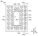
- FIG. 9 is a diagram showing the shape of the insulating plate according to the second embodiment of the present invention.
- FIG. 10 is a cross-sectional view of the insulating plate shown in FIG. 9 as viewed from the direction of the XX line arrow.
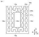
- FIG. 11 is a diagram showing the shape of the first plate-shaped portion of the insulating plate according to the second embodiment of the present invention.
- FIG. 12 is a diagram showing the shape of the second plate-shaped portion of the insulating plate according to the second embodiment of the present invention.
- the plurality of insulating plates 230 according to the second embodiment of the present invention have the plurality of first hole portions 231a of the first plate-shaped portion 230a when viewed from the central axis direction. Further, each corner of the second hole portion 231b of the second plate-shaped portion 230b is rounded. As a result, the pressure loss in the flow path 10 when the insulating oil flows through the flow path 10 can be reduced.
- the plurality of first notch portions 232b, the plurality of second notch portions 233a and 233b, and the plurality of inner peripheral notch portions 239a and 239b are also rounded. Includes tinged corners.
- the rest guidance device according to the third embodiment of the present invention is mainly the position of each of the plurality of first holes and the plurality of second holes with the rest guidance device 100 according to the first embodiment of the present invention. different. Therefore, the description of the configuration similar to that of the rest guidance device 100 according to the first embodiment of the present invention will not be repeated.
- FIG. 13 is a diagram showing the shape of the insulating plate according to the third embodiment of the present invention.
- FIG. 14 is a view of the insulating plate shown in FIG. 13 as viewed from the direction of the XIV-XIV line arrow.
- FIG. 15 is a view of the insulating plate shown in FIG. 13 as viewed from the direction of the XV-XV line arrow.
- FIG. 16 is a diagram showing the shape of the first plate-shaped portion of the insulating plate according to the third embodiment of the present invention.
- FIG. 17 is a diagram showing the shape of the second plate-shaped portion of the insulating plate according to the third embodiment of the present invention.
- each of the plurality of first hole portions 331a of the first plate-shaped portion 330a is a plurality of straight lines adjacent to each other. It constitutes a part of one of the linear flow paths 11X. As shown in FIGS. 13 and 15, each of the plurality of first hole portions 331a constitutes a part of the other linear flow path 11Y among the plurality of linear flow paths adjacent to each other. As shown in FIGS. 13 and 16, the plurality of first hole portions 331a constituting one linear flow path 11X and the plurality of first hole portions 331a constituting the other linear flow path 11Y are first. They are staggered in direction D1.
- each of the plurality of second hole portions 331b of the second plate-shaped portion 330b is one of the linear flow paths 11X of the plurality of linear flow paths 11 adjacent to each other. It constitutes a part. As shown in FIGS. 13 and 15, each of the plurality of second hole portions 331b constitutes a part of the other linear flow path 11Y among the plurality of linear flow paths adjacent to each other. As shown in FIGS. 13 and 17, the plurality of second hole portions 331b constituting one linear flow path 11X and the plurality of second hole portions 331b constituting the other linear flow path 11Y are the first. They are staggered in direction D1 of 1.
- the portion of the plurality of windings 120 that is not adjacent to one linear flow path 11X is the other. It is adjacent to the linear flow path 11Y. Further, when viewed from the second direction D2, the portion of the plurality of windings 120 that is not adjacent to the other linear flow path 11Y is adjacent to one linear flow path 11X. Thereby, each of the plurality of insulating plates 330 and each of the plurality of windings 120 adjacent to each other can be uniformly cooled.
- the rest guidance device according to the fourth embodiment of the present invention is mainly the position of each of the plurality of first holes and the plurality of second holes with the rest guidance device 100 according to the first embodiment of the present invention. different. Therefore, the description of the configuration similar to that of the rest guidance device 100 according to the first embodiment of the present invention will not be repeated.
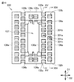
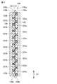
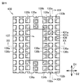
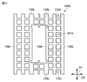
- FIG. 18 is a diagram showing the shape of the insulating plate according to the fourth embodiment of the present invention.
- FIG. 19 is a view of the insulating plate shown in FIG. 18 as viewed from the direction of the XIX-XIX line arrow.
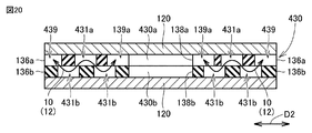
- FIG. 20 is a view of the insulating plate shown in FIG. 18 as viewed from the direction of the XX-XX line arrow.
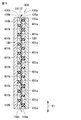
- FIG. 21 is a diagram showing the shape of the first plate-shaped portion of the insulating plate according to the fourth embodiment of the present invention.
- FIG. 22 is a diagram showing the shape of the second plate-shaped portion of the insulating plate according to the fourth embodiment of the present invention.
- the first plate-shaped portion 430a and the second plate-shaped portion 430b cause one side of each of the plurality of insulating plates 430 in the first direction D1.
- a plurality of flow paths 10 are configured so that the insulating oil can flow through the other side and the other side.
- insulating oil can flow from the side edge edges 136a and 136b to the inner peripheral edge edges 138a and 138b in the second direction D2.
- the flow path 10 is configured. As shown in FIG. 20, the flow path 10 along the second direction D2 is formed in, for example, a plurality of first hole portions 431a, a plurality of second hole portions 431b, an inner peripheral notch portion 139a, and a lateral end edge 136a.
- the side cutouts 439 are overlapped with each other.
- Each of the flow paths 10 of the above is connected to each other.
- the flow path 10 includes the reticulated flow path 12 when viewed from the central axis direction.
- each of the plurality of first hole portions 431a and the plurality of second hole portions 431b is viewed from the central axis direction.
- the central portion of each of the plurality of first hole portions 431a and the central portion of each of the plurality of second hole portions 431b are located in a zigzag shape with respect to each other.
- the flow path 10 includes a braided flow path 12. Since the insulating oil can flow while taking various paths in the net-like flow path 12, the plurality of windings 120 in contact with each of the plurality of insulating plates 430 can be cooled more uniformly.
- Embodiment 5 the rest guidance device according to the fifth embodiment of the present invention will be described.
- the static induction device according to the fifth embodiment of the present invention is mainly different from the static induction device according to the fourth embodiment of the present invention in the number of plate-shaped portions constituting the insulating plate. Therefore, the description of the configuration similar to that of the stationary guidance device according to the fourth embodiment of the present invention will not be repeated.
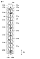
- FIG. 23 is a cross-sectional view showing the configuration of the insulating plate according to the fifth embodiment of the present invention. In addition, in FIG. 23, it is shown in the same cross-sectional view as FIG. 19 showing the insulating plate 430 of the fourth embodiment of the present invention.
- the plurality of insulating plates 530 and the second plate-shaped portion 430b on the side opposite to the first plate-shaped portion 430a side in the central axis direction.
- An adjacent third plate-shaped portion 530c is further provided.
- the plurality of insulating plates 530 are composed of a first plate-shaped portion 430a, a second plate-shaped portion 430b, and a third plate-shaped portion 530c.
- the third plate-shaped portion 530c has the same shape as the first plate-shaped portion 430a, and is located so as to be symmetrical with respect to the first plate-shaped portion 430a with respect to the second plate-shaped portion 430b.
Landscapes
- Engineering & Computer Science (AREA)
- Power Engineering (AREA)
- Chemical & Material Sciences (AREA)
- Combustion & Propulsion (AREA)
- Coils Of Transformers For General Uses (AREA)
- Insulating Of Coils (AREA)
- Transformer Cooling (AREA)
Priority Applications (4)
| Application Number | Priority Date | Filing Date | Title |
|---|---|---|---|
| EP19926516.6A EP3961663B1 (de) | 2019-04-25 | 2019-04-25 | Stationäre induktionsvorrichtung |
| US17/429,081 US12009134B2 (en) | 2019-04-25 | 2019-04-25 | Stationary induction apparatus |
| JP2019547737A JP6612009B1 (ja) | 2019-04-25 | 2019-04-25 | 静止誘導機器 |
| PCT/JP2019/017608 WO2020217376A1 (ja) | 2019-04-25 | 2019-04-25 | 静止誘導機器 |
Applications Claiming Priority (1)
| Application Number | Priority Date | Filing Date | Title |
|---|---|---|---|
| PCT/JP2019/017608 WO2020217376A1 (ja) | 2019-04-25 | 2019-04-25 | 静止誘導機器 |
Publications (1)
| Publication Number | Publication Date |
|---|---|
| WO2020217376A1 true WO2020217376A1 (ja) | 2020-10-29 |
Family
ID=68692061
Family Applications (1)
| Application Number | Title | Priority Date | Filing Date |
|---|---|---|---|
| PCT/JP2019/017608 Ceased WO2020217376A1 (ja) | 2019-04-25 | 2019-04-25 | 静止誘導機器 |
Country Status (4)
| Country | Link |
|---|---|
| US (1) | US12009134B2 (de) |
| EP (1) | EP3961663B1 (de) |
| JP (1) | JP6612009B1 (de) |
| WO (1) | WO2020217376A1 (de) |
Families Citing this family (1)
| Publication number | Priority date | Publication date | Assignee | Title |
|---|---|---|---|---|
| CN115380342A (zh) * | 2020-03-31 | 2022-11-22 | 通用电气公司 | 用于高功率密度(hpd)变压器的液体/流体冷却系统 |
Citations (4)
| Publication number | Priority date | Publication date | Assignee | Title |
|---|---|---|---|---|
| JPS4883365A (de) * | 1972-02-05 | 1973-11-07 | ||
| JPS5426623U (de) * | 1977-07-26 | 1979-02-21 | ||
| JPS58196814U (ja) | 1982-06-24 | 1983-12-27 | 株式会社東芝 | 外鉄形油入変圧器 |
| WO2016009521A1 (ja) * | 2014-07-17 | 2016-01-21 | 三菱電機株式会社 | 車載用変圧装置 |
Family Cites Families (3)
| Publication number | Priority date | Publication date | Assignee | Title |
|---|---|---|---|---|
| JPS5033616Y1 (de) | 1969-12-17 | 1975-10-01 | ||
| US7760060B2 (en) * | 2006-07-10 | 2010-07-20 | Mitsubishi Electric Corporation | Vehicle transformer |
| US8547193B2 (en) | 2009-10-21 | 2013-10-01 | Mitsubishi Electric Corporation | Stationary induction apparatus |
-
2019
- 2019-04-25 EP EP19926516.6A patent/EP3961663B1/de active Active
- 2019-04-25 WO PCT/JP2019/017608 patent/WO2020217376A1/ja not_active Ceased
- 2019-04-25 JP JP2019547737A patent/JP6612009B1/ja not_active Expired - Fee Related
- 2019-04-25 US US17/429,081 patent/US12009134B2/en active Active
Patent Citations (4)
| Publication number | Priority date | Publication date | Assignee | Title |
|---|---|---|---|---|
| JPS4883365A (de) * | 1972-02-05 | 1973-11-07 | ||
| JPS5426623U (de) * | 1977-07-26 | 1979-02-21 | ||
| JPS58196814U (ja) | 1982-06-24 | 1983-12-27 | 株式会社東芝 | 外鉄形油入変圧器 |
| WO2016009521A1 (ja) * | 2014-07-17 | 2016-01-21 | 三菱電機株式会社 | 車載用変圧装置 |
Non-Patent Citations (1)
| Title |
|---|
| See also references of EP3961663A4 |
Also Published As
| Publication number | Publication date |
|---|---|
| EP3961663A4 (de) | 2022-05-04 |
| US20220020520A1 (en) | 2022-01-20 |
| US12009134B2 (en) | 2024-06-11 |
| JPWO2020217376A1 (ja) | 2021-05-13 |
| EP3961663A1 (de) | 2022-03-02 |
| EP3961663B1 (de) | 2023-12-20 |
| JP6612009B1 (ja) | 2019-11-27 |
Similar Documents
| Publication | Publication Date | Title |
|---|---|---|
| US3183461A (en) | Magnetic core structure with cooling passages therein | |
| JP7087083B2 (ja) | 変圧器鉄心および変圧器 | |
| JPH04212403A (ja) | 磁芯用薄板 | |
| CN110914938B (zh) | 平面型变压器和dcdc转换器 | |
| KR20000074890A (ko) | 방열 리브를 가지는 고압 트랜스포머 | |
| US20170221629A1 (en) | Transformer having a stacked core | |
| KR102298557B1 (ko) | 무부하 손실 및 무부하 소음이 우수한 변압기용 적철심 및 이의 제조 방법 | |
| JP7488824B2 (ja) | 巻鉄心 | |
| WO2020217376A1 (ja) | 静止誘導機器 | |
| US1938421A (en) | Spacer for electrical winding coils | |
| US20160268035A1 (en) | Vehicle-mounted transformer | |
| US2407625A (en) | Magnetic core | |
| JP5717011B2 (ja) | 高周波誘導加熱装置用変成器 | |
| US4257025A (en) | Laminated metallic plates for supporting core leg in inductive electrical devices to determine magnetic circuit | |
| US3270307A (en) | Laminated magnetic core joint structure | |
| JP2013191623A (ja) | リアクトル | |
| US1549525A (en) | Spacer for transformer disk coils | |
| US2812505A (en) | Magnetic core for stationary electrical induction apparatus | |
| US9941043B2 (en) | Core for an electrical induction device | |
| CN109923626B (zh) | 用于电感应装置的芯体 | |
| JPH0145204B2 (de) | ||
| US1317280A (en) | Of stretfobb | |
| US3201733A (en) | Magnetic core structures | |
| JP7199606B1 (ja) | 静止誘導機器 | |
| JP6871731B2 (ja) | 変圧器 |
Legal Events
| Date | Code | Title | Description |
|---|---|---|---|
| ENP | Entry into the national phase |
Ref document number: 2019547737 Country of ref document: JP Kind code of ref document: A |
|
| 121 | Ep: the epo has been informed by wipo that ep was designated in this application |
Ref document number: 19926516 Country of ref document: EP Kind code of ref document: A1 |
|
| NENP | Non-entry into the national phase |
Ref country code: DE |
|
| ENP | Entry into the national phase |
Ref document number: 2019926516 Country of ref document: EP Effective date: 20211125 |