WO2020217704A1 - Dispositif de communication et procédé de communication - Google Patents
Dispositif de communication et procédé de communication Download PDFInfo
- Publication number
- WO2020217704A1 WO2020217704A1 PCT/JP2020/008112 JP2020008112W WO2020217704A1 WO 2020217704 A1 WO2020217704 A1 WO 2020217704A1 JP 2020008112 W JP2020008112 W JP 2020008112W WO 2020217704 A1 WO2020217704 A1 WO 2020217704A1
- Authority
- WO
- WIPO (PCT)
- Prior art keywords
- data
- queue
- band
- communication device
- bands
- Prior art date
- Legal status (The legal status is an assumption and is not a legal conclusion. Google has not performed a legal analysis and makes no representation as to the accuracy of the status listed.)
- Ceased
Links
Images










Classifications
-
- H—ELECTRICITY
- H04—ELECTRIC COMMUNICATION TECHNIQUE
- H04L—TRANSMISSION OF DIGITAL INFORMATION, e.g. TELEGRAPHIC COMMUNICATION
- H04L1/00—Arrangements for detecting or preventing errors in the information received
- H04L1/12—Arrangements for detecting or preventing errors in the information received by using return channel
- H04L1/16—Arrangements for detecting or preventing errors in the information received by using return channel in which the return channel carries supervisory signals, e.g. repetition request signals
- H04L1/1607—Details of the supervisory signal
- H04L1/1614—Details of the supervisory signal using bitmaps
-
- H—ELECTRICITY
- H04—ELECTRIC COMMUNICATION TECHNIQUE
- H04W—WIRELESS COMMUNICATION NETWORKS
- H04W28/00—Network traffic management; Network resource management
- H04W28/02—Traffic management, e.g. flow control or congestion control
- H04W28/10—Flow control between communication endpoints
- H04W28/14—Flow control between communication endpoints using intermediate storage
-
- H—ELECTRICITY
- H04—ELECTRIC COMMUNICATION TECHNIQUE
- H04L—TRANSMISSION OF DIGITAL INFORMATION, e.g. TELEGRAPHIC COMMUNICATION
- H04L1/00—Arrangements for detecting or preventing errors in the information received
- H04L1/08—Arrangements for detecting or preventing errors in the information received by repeating transmission, e.g. Verdan system
-
- H—ELECTRICITY
- H04—ELECTRIC COMMUNICATION TECHNIQUE
- H04L—TRANSMISSION OF DIGITAL INFORMATION, e.g. TELEGRAPHIC COMMUNICATION
- H04L1/00—Arrangements for detecting or preventing errors in the information received
- H04L1/12—Arrangements for detecting or preventing errors in the information received by using return channel
- H04L1/16—Arrangements for detecting or preventing errors in the information received by using return channel in which the return channel carries supervisory signals, e.g. repetition request signals
- H04L1/18—Automatic repetition systems, e.g. Van Duuren systems
- H04L1/1867—Arrangements specially adapted for the transmitter end
- H04L1/1874—Buffer management
-
- H—ELECTRICITY
- H04—ELECTRIC COMMUNICATION TECHNIQUE
- H04L—TRANSMISSION OF DIGITAL INFORMATION, e.g. TELEGRAPHIC COMMUNICATION
- H04L1/00—Arrangements for detecting or preventing errors in the information received
- H04L1/12—Arrangements for detecting or preventing errors in the information received by using return channel
- H04L1/16—Arrangements for detecting or preventing errors in the information received by using return channel in which the return channel carries supervisory signals, e.g. repetition request signals
- H04L1/18—Automatic repetition systems, e.g. Van Duuren systems
- H04L1/1867—Arrangements specially adapted for the transmitter end
- H04L1/1887—Scheduling and prioritising arrangements
-
- H—ELECTRICITY
- H04—ELECTRIC COMMUNICATION TECHNIQUE
- H04L—TRANSMISSION OF DIGITAL INFORMATION, e.g. TELEGRAPHIC COMMUNICATION
- H04L1/00—Arrangements for detecting or preventing errors in the information received
- H04L1/12—Arrangements for detecting or preventing errors in the information received by using return channel
- H04L1/16—Arrangements for detecting or preventing errors in the information received by using return channel in which the return channel carries supervisory signals, e.g. repetition request signals
- H04L1/18—Automatic repetition systems, e.g. Van Duuren systems
- H04L1/1867—Arrangements specially adapted for the transmitter end
- H04L1/1893—Physical mapping arrangements
-
- H—ELECTRICITY
- H04—ELECTRIC COMMUNICATION TECHNIQUE
- H04W—WIRELESS COMMUNICATION NETWORKS
- H04W28/00—Network traffic management; Network resource management
- H04W28/02—Traffic management, e.g. flow control or congestion control
- H04W28/04—Error control
-
- H—ELECTRICITY
- H04—ELECTRIC COMMUNICATION TECHNIQUE
- H04W—WIRELESS COMMUNICATION NETWORKS
- H04W28/00—Network traffic management; Network resource management
- H04W28/02—Traffic management, e.g. flow control or congestion control
- H04W28/10—Flow control between communication endpoints
- H04W28/12—Flow control between communication endpoints using signalling between network elements
Definitions
- the technology disclosed in the present specification relates to a communication device and a communication method for transmitting and receiving radio signals using a plurality of bands.
- the transmission data is distributed to an appropriate band, and the transmission power is set according to the band to control the SINR (Signal to Reference plus Noise Radio) on the receiving side.
- SINR Signal to Reference plus Noise Radio
- An object of the technique disclosed in the present specification is to provide a communication device and a communication method for transmitting and receiving radio signals using a plurality of bands by a queue configuration corresponding to a plurality of bands.
- the second queue stores data that requires low delay and high reliability as data to be transmitted with high priority.
- the second queue also stores the retransmission data along with information about the first transmitted band. Then, the control unit controls the retransmission data output from the second queue to be transmitted by adding information regarding the band initially transmitted.
- control unit adds information on the amount of data stored in the second queue to the retransmission data output from the second queue and transmits the data.
- the information regarding the amount of data includes information regarding the amount of all data stored in the second queue. Further, the information regarding the amount of data includes information regarding the amount of data stored in the sub-queue in the second queue corresponding to the data type of the retransmission data.
- a communication device that receives data in multiple bands
- An information receiving unit that receives information about a first queue for each band and a second queue common to at least two of the plurality of bands.
- a data receiving unit that receives data in which information indicating the order and information indicating the first transmitted band are added to at least one of the plurality of bands. It is a communication device provided with.
- the fourth aspect of the technology disclosed herein is: A communication method that receives data in multiple bands. A step of receiving information about a first queue for each band and a second queue common to at least two of the plurality of bands. A step of receiving data in which information indicating the order and information indicating the first transmitted band are added to at least one of the plurality of bands. It is a communication method having.
- a communication device and a communication method for transmitting and receiving radio signals using a plurality of bands by a queue configuration including a queue for each band and a queue for transmitting a plurality of bands.
- FIG. 1 is a diagram showing a configuration example of the communication system 100.
- FIG. 2 is a diagram showing a functional configuration example of the communication device 200.
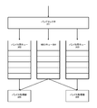
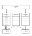
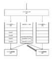
- FIG. 3 is a diagram showing a configuration example of a queue corresponding to transmission in a plurality of bands.
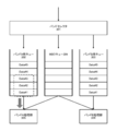
- FIG. 4 is a diagram showing another configuration example of a queue corresponding to transmission in a plurality of bands.
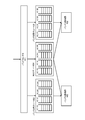
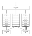
- FIG. 5 is a diagram illustrating still another configuration of the queue corresponding to transmission in a plurality of bands.
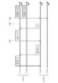
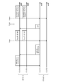
- FIG. 6 is a diagram showing an example of a communication sequence when data communication is performed between AP101 and STA102 using bands A and B.
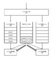
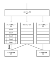
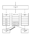
- FIG. 7 is a diagram showing an operation example of the queue when the data communication shown in FIG. 6 is performed.
- FIG. 7 is a diagram showing an operation example of the queue when the data communication shown in FIG. 6 is performed.
- FIG. 14 is a diagram showing still another communication sequence example in the case of performing data communication between AP101 and STA102 using bands A and B.
- FIG. 15 is a diagram showing an operation example of the queue when the data communication shown in FIG. 14 is performed.
- FIG. 16 is a diagram showing an operation example of the queue when the data communication shown in FIG. 14 is performed.
- FIG. 17 is a diagram showing an operation example of the queue when the data communication shown in FIG. 14 is performed.
- FIG. 18 is a diagram showing an operation example of the queue when the data communication shown in FIG. 14 is performed.
- FIG. 19 is a diagram showing an operation example of the queue when the data communication shown in FIG. 14 is performed.
- FIG. 15 is a diagram showing an operation example of the queue when the data communication shown in FIG. 14 is performed.
- FIG. 16 is a diagram showing an operation example of the queue when the data communication shown in FIG. 14 is performed.
- FIG. 17 is a diagram showing an operation example of the queue when the data communication shown in FIG.
- FIG. 1 shows a schematic configuration example of a communication system 100 to which the technique proposed in the present specification is applied.
- the illustrated communication system 100 is composed of one base station (AP) 101 and one slave unit (STA) 102. Further, in the communication system 100, it is assumed that two bands, band A and band B, can be used.
- the slave unit 102 is connected to the base station 101, and the channel in the band A and the channel in the band B can be bundled and communicated between the base station 101 and the slave unit 102.
- band A and band B may be a band permitted to be used by database access.
- Band A and band B are, for example, 2.4 GHz band, 5 GHz band, or 6 GHz band, respectively.
- Band A and band B each include a plurality of channels, one of which is the primary channel.
- the number, positional relationship, and frequency of the communication devices constituting the communication system 100 shown in FIG. 1 are examples, and are not limited to the description here.
- a network topology in which two or more slave units are connected to one base station is also assumed.
- a plurality of different channels in each of the bands A and B may be bundled for communication.
- communication is performed between the base station 101 and the slave unit 102 by adding one or more bands in addition to the bands A and B and using a total of three or more bands. ..
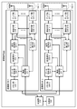
- FIG. 2 shows a functional configuration example of a communication device 200 capable of operating as either a base station 101 or a slave unit 102 in the communication system 100 according to the present embodiment.
- the illustrated communication device 200 includes a control unit 210, a power supply unit 220, a plurality of (two in the illustrated example) communication units 230-1, a communication unit 230-2, and an antenna corresponding to the communication unit 230-1. It is composed of a unit 240-1 and an antenna unit 240-2 corresponding to the communication unit 230-2.
- the communication unit 230-1 and the communication unit 230-2, and the antenna unit 240-1 and the antenna unit 240-2 have the same configuration, they will be referred to as the communication unit 230 and the antenna unit 240 in the following for simplification. To.
- the communication unit 230 is composed of a processor or a circuit such as a microprocessor, and includes a memory unit 238, a wireless control unit 231, a data processing unit 232, a modulation / demodulation unit 233, a signal processing unit 234, and a channel estimation unit 235. , ..., 236-N and a plurality of wireless interface (IF) units 236-1, ..., 236-N arranged in parallel, and an amplifier unit 237- connected in series to each wireless interface unit 236-1, ..., 236-N. 1, ..., 237-N (however, N is an integer of 2 or more). Then, each antenna element constituting the antenna unit 240 corresponding to the communication unit 230 is connected to each amplifier unit 237-1, ..., 237-N.
- IF wireless interface
- the memory unit 238 temporarily stores data (for example, transmission data) input from the upper layer of the communication protocol and provides it to the data processing unit 232. Further, the memory unit 239 temporarily stores the data (for example, received data) passed from the data processing unit 232 and provides it to the upper layer of the communication protocol. That is, the memory unit 238 is used as a transmission queue or a reception queue.
- the memory unit 238 may be arranged outside the communication unit 230. Further, the memory unit 238-1 arranged in one communication unit 230-1 may be shared with another communication unit 230-2, or the memory unit 238 arranged outside the communication unit 230 may be shared with a plurality of communication units. It may be shared by 230-1, 230-2, ....
- the data processing unit 232 generates a packet for wireless transmission from the data when data is input from the upper layer of its own communication protocol, and further performs media access control (MAC) for media access control (MAC). Processing such as addition of a header and addition of an error detection code is performed, and the processed data is provided to the modulation / demodulation unit 233. Further, the data processing unit 232 performs MAC header analysis, packet error detection, packet reorder processing, etc. when receiving an input from the modulation / demodulation unit 233, and outputs the processed data to its own protocol upper layer. Provide to the layer.
- MAC media access control
- MAC media access control
- the modulation / demodulation unit 233 performs coding, interleaving, and modulation processing on the input data from the data processing unit 232 based on the coding method and the modulation method set by the wireless control unit 231 to perform the data symbol stream. Is generated and provided to the signal processing unit 234. Further, the modulation / demodulation unit 233 performs demodulation processing, deinterleaving, and decoding processing opposite to those at the time of transmission on the input symbol stream from the signal processing unit 234 at the time of reception, and the data processing unit 232 or the wireless control unit. Data is provided to 231.
- the signal processing unit 234 performs signal processing for spatial separation on the input from the modulation / demodulation unit 233 as necessary, and transfers the obtained one or more transmission symbol streams to the respective wireless interface units 236-. Provided to 1. Further, at the time of reception, the signal processing unit 234 performs signal processing on the received symbol stream input from each wireless interface unit 236-1, ..., And spatially decomposes the stream as necessary to perform modulation / demodulation unit. Provided to 233.
- the wireless interface unit 236 converts the input from the signal processing unit 234 into an analog signal, performs filtering, up-conversion to the carrier frequency, and phase control, and sends the input to the corresponding amplifier unit 237 or antenna unit 240. To do. Further, at the time of reception, the wireless interface unit 236 performs processing such as down-conversion, filtering, and conversion to a digital signal on the input from the corresponding amplifier unit 237 or the antenna unit 240, which is opposite to that at the time of transmission. Data is provided to the signal processing unit 234 and the channel estimation unit 235.
- the amplifier unit 237 At the time of transmission, the amplifier unit 237 amplifies the analog signal input from the wireless interface unit 236 to a predetermined power and sends it to the corresponding antenna element in the antenna unit 240. Further, at the time of reception, the amplifier unit 237 amplifies the signal input from the corresponding antenna element in the antenna unit 240 to a predetermined power with low noise, and outputs the signal to the wireless interface unit 236.
- At least one of the transmission function and the reception function of the amplifier unit 237 may be included in the wireless interface unit 236. Further, in the amplifier unit 237, at least one of the function at the time of transmission and the function at the time of reception may be a component other than the communication unit 230.
- a set of wireless interface unit 236 and amplifier unit 237 constitutes one RF (Radio Frequency) branch. It is assumed that one RF branch can transmit and receive one band.
- the communication unit 230 includes N RF branches.
- the control unit 210 is composed of a processor or a circuit such as a microprocessor, and controls the wireless control unit 231 and the power supply unit 220. Further, the control unit 210 may perform at least a part of the above-described operation of the radio control unit 231 instead of the radio control unit 231. In particular, in the present embodiment, the control unit 210 and the wireless control unit 231 control the operation of each unit in order to realize the operation according to each embodiment described later.
- the power supply unit 220 is composed of a battery power supply or a fixed power supply, and supplies power for driving to the communication device 200.
- control unit 210 and the communication unit 230 can be combined with one or a plurality of LSIs (Large Scale Integration).
- the communication unit 230 may be configured to transition to a standby state or a sleep state (or a state in which at least some functions are stopped) to reduce power consumption. Good.
- the communication unit 230 includes N RF branches, but it may be configured so that each RF branch can transition to a standby state or a sleep state.
- the communication device 200 includes a queue for transmitting a plurality of bands in addition to a queue for each band. Then, the communication device 200 stores the data to be transmitted with high priority in the multi-band transmission queue.
- the data transmitted with high priority includes, for example, data that requires low delay and high reliability, and retransmission data that is transmitted in each band and fails in communication.
- the communication device 200 when storing data transmitted in each band and communication failure in a queue for transmitting multiple bands, it is stored together with information on which band the data was transmitted in the first transmission. After that, when the communication device 200 acquires the transmission right in any of the bands, the operation of extracting the data from the multi-band transmission queue and transmitting using that band is performed. For example, when the communication device acquires the transmission right in a plurality of bands, the data extracted from the multi-band transmission queue is transmitted using the plurality of bands. Further, when the communication device 200 acquires the transmission right in a band other than the band in which the communication fails, the communication device 200 extracts the data from the multi-band transmission queue instead of the queue in that band, and obtains the transmission right in the band. It performs the operation of transmitting using.
- the communication device 200 can retransmit the same data in a plurality of bands to ensure redundancy. Further, the communication device 200 can perform retransmission while avoiding a band having poor propagation characteristics in which communication has failed. In addition, the communication device 200 improves the success rate of retransmission and improves reliability. Further, the communication device 200 can suppress an increase in delay due to the occurrence of a plurality of retransmissions. In addition, the communication device 200 can reduce a plurality of retransmissions and improve the throughput of the system. In addition, the communication device 200 can reduce the amount of data to be held on the receiving side and reduce the amount of memory required.
- control unit 210 and the wireless control unit 231 transmit and receive a signal including information regarding the multi-band transmission queue, and store the data in which communication fails in the multi-band transmission queue together with the information regarding the band in which the data is transmitted. Then, the operation of each part in the communication device 200 is controlled so that the data is taken out from the multi-band transmission queue and the plurality of bands are transmitted at the time of retransmission.
- band A and band B are a band permitted to be used by database access
- the control unit 210 and the radio control unit 231 shall also control the access operation to the database. ..
- the communication system 100 shown in FIG. 1 a case where AP101 and STA102 communicate using two bands will be described.
- at least one of the two bands used for communication may be a band permitted to be used by database access (in this case, it is assumed that the band is used after accessing the database).
- the AP101 and the STA102 include the device configuration of the communication system 200 shown in FIG.
- FIG. 3 shows a configuration example of a queue 300 equipped with AP101 and STA102, respectively, which supports transmission in a plurality of bands.
- the band selector 301 determines in which band the input data is stored, and outputs the data to either the determined band A queue 302 or the band B queue 303. Further, the band selector 301 decides to store the data to be transmitted with high priority in the multi-band operation (MBO) queue 304, and outputs the data to the MBO queue 304.
- the data to be transmitted with high priority includes, for example, data requiring low delay and high reliability and retransmission data.
- the band A processing unit 305 and the band B processing unit 306 perform processing so as to acquire transmission rights in the corresponding bands (band A and band B) and to transmit the input data in the corresponding bands.
- the band A processing unit 305 and the band B processing unit 306 may input data that needs to be retransmitted to the MBO queue 304 after transmission in each band.
- the communication device 200 acquires the transmission right in any of the bands, data is output from the queue corresponding to that band to either the band A processing unit 305 or the band B processing unit 306.
- the data stored in the band A queue 302 is output to the band A processing unit 305 by the FIFO method.
- the transmission right of the band B is acquired, the data stored in the band B queue 303 is output to the band B processing unit 306 by the FIFO method.
- the data is output from the MBO queue 304 to the band A processing unit 305 or the band B processing unit 306 by the FIFO method instead of the respective queues 302 and 303 corresponding to the band.
- the communication device 200 acquires the transmission right in both the bands A and B and the data is stored in the MBO queue 304, the same data is sent from the MBO queue 304 to the band A processing unit. Output to both 305 and band B processing unit 306.
- the wireless control unit 231 in the control unit 210 or the communication unit 230 for each band may realize the function corresponding to the band selector 301 in FIG. Further, the memory unit 238-1 in the communication unit 230-1 for band A realizes the function corresponding to the queue 302 for band A, and the memory unit 238-2 in the communication unit 230-2 for band B realizes the function. The function corresponding to the band B cue 303 may be realized. Either one or both of the memory unit 238-1 and the memory unit 238-2 may realize the function of the MBO queue 304. Alternatively, a memory (not shown) arranged outside the communication unit 230 may realize the function of the MBO queue 304.
- the data processing unit 232-1 in the communication unit 230-1, the communication components from the modulation / demodulation unit 233-1 to the amplifier unit 237-1, and the antenna unit 240-1 corresponding to the communication unit 230-1 are in band A.
- the function of the processing unit 305 may be realized.
- the control unit 210 and the wireless control unit 231-1 may realize some functions of the band A processing unit 305.
- the function of the band B processing unit 306 may be realized.
- the control unit 210 and the wireless control unit 231-2 may realize some functions of the band B processing unit 306.
- FIG. 4 shows another configuration example of the queue 400 equipped with AP101 and STA102, which supports transmission in a plurality of bands.
- the band selector 401 determines in which band the input data is stored, and outputs the data to either the determined band A queue 402 or the band B queue 403. Further, the band selector 401 decides to store the data to be transmitted with high priority in the MBO queue 404, and outputs the data to the MBO queue 404.
- the data to be transmitted with high priority includes, for example, data requiring low delay and high reliability and retransmission data.
- each queue 402, 403, and 404 is configured as a set of a plurality of sub-queues corresponding to the data type of the data to be stored.
- EDCA Enhanced Distributed Channel Access
- Voice AC_VO
- Video AC_VI
- Waistcoat AC_BE
- Back Access AC_BE
- BackGround Also referred to as "AC”
- Each of the queues 402, 403, and 404 includes four sub-queues corresponding to each access category, and each sub-queue temporarily stores the data of the corresponding access category in the FIFO format.
- the band A processing unit 405 and the band B processing unit 406 perform processing so as to acquire transmission rights in the corresponding bands (band A and band B) and to transmit the input data in the corresponding bands. Then, the band A processing unit 405 and the band B processing unit 406 may input data that needs to be retransmitted to the MBO queue 404 after transmission in each band.
- the communication device 200 acquires the transmission right in any of the bands, data is output from the queue corresponding to that band to either the band A processing unit 405 or the band B processing unit 406.
- the data is output to the band A processing unit 405 by the FIFO method in order from the sub queue corresponding to the access category having the highest priority in the band A queue 402. .
- the transmission right of the band B is acquired, the data is output to the band B processing unit 406 by the FIFO method in order from the sub queue corresponding to the access category having the highest priority in the band B queue 403. ..
- the wireless control unit 231 in the control unit 210 or the communication unit 230 for each band may realize the function corresponding to the band selector 401 in FIG. Further, the memory unit 238-1 in the communication unit 230-1 for band A realizes the function corresponding to the queue 402 for band A, and the memory unit 238-2 in the communication unit 230-2 for band B realizes the function.
- the function corresponding to the band B queue 403 may be realized. Either or both of the memory unit 238-1 and the memory unit 238-2 may realize the function of the MBO queue 404. Alternatively, a memory (not shown) arranged outside the communication unit 230 may realize the function of the MBO queue 404.
- the data processing unit 232-1 in the communication unit 230-1, the communication components from the modulation / demodulation unit 233-1 to the amplifier unit 237-1, and the antenna unit 240-1 corresponding to the communication unit 230-1 are in band A.
- the function of the processing unit 405 may be realized.
- the control unit 210 and the wireless control unit 231-1 may realize some functions of the band A processing unit 405.
- the function of the band B processing unit 406 may be realized.
- the control unit 210 and the wireless control unit 231-2 may realize some functions of the band B processing unit 406.
- FIG. 5 shows still another configuration example of the queue 500 equipped with AP101 and STA102, which supports transmission in a plurality of bands.
- the band selector 501 determines which band the input data is stored in, and outputs the data to either the determined band A queue 502 or the band B queue 503. Further, the band selector 501 decides to store the data to be transmitted with high priority in the MBO queue 504, and outputs the data to the MBO queue 504.
- the data to be transmitted with high priority includes, for example, data requiring low delay and high reliability and retransmission data.
- each queue 502, 503, and 504 is configured as a set of a plurality of sub-queues corresponding to the data type of the data to be stored. Each subqueue temporarily stores the data of the corresponding data type in the FIFO format.
- Data The data type referred to here corresponds to the access category defined in the EDCA method of IEEE802.11e (same as above).
- the band A queue 502 and the band B queue 503 are composed of the number of sub-queues corresponding to all access categories
- the MBO queue 504 is composed of only the sub-queues corresponding to some access categories. It is composed.
- the number of sub-queues differs between the band A queue 502, the band B queue 503, and the MBO queue 504.
- the MBO queue 504 is equipped with only sub-queues corresponding to the two access categories of high priority Voice (AC_VO) and Video (AC_VI).
- the band A processing unit 505 and the band B processing unit 506 each perform processing to acquire transmission rights in the corresponding bands (band A, band B) and transmit the input data in the corresponding bands. Then, the band A processing unit 505 and the band B processing unit 506 store only the data of the access category in which the MBO queue 504 corresponds to the sub queue among the data that needs to be retransmitted after being transmitted in each band in the MBO queue 504. Fill in the corresponding subqueue of. Of the data that needs to be retransmitted, data that does not fall under any of the access categories of the sub-queues installed in the MBO queue 504 may be discarded by giving up the retransmission.
- the communication device 200 acquires the transmission right in any band
- data is output from the queue corresponding to that band to either the band A processing unit 505 or the band B processing unit 506.
- the data is output to the band A processing unit 505 by the FIFO method in order from the sub queue corresponding to the access category having the highest priority in the band A queue 502. .
- the transmission right of the band B is acquired, the data is output to the band B processing unit 506 by the FIFO method in order from the sub queue corresponding to the access category having the highest priority in the band B queue 503. ..
- the band is sent from the MBO queue 504 instead of the queues 502 and 503 for each band.
- Data is output to the A processing unit 505 or the band B processing unit 506.
- the same data is sent from the MBO queue 504 to the band A processing unit. It is output to both 405 and band B processing unit 506.
- data is output to one or both of the band A processing unit 505 and the band B processing unit 506 in order from the sub queue corresponding to the access category with the highest priority by the FIFO method.
- the wireless control unit 231 in the control unit 210 or the communication unit 230 for each band may realize the function corresponding to the band selector 501 in FIG. Further, the memory unit 238-1 in the communication unit 230-1 for band A realizes the function corresponding to the queue 502 for band A, and the memory unit 238-2 in the communication unit 230-2 for band B realizes the function. The function corresponding to the band B cue 503 may be realized. Either one or both of the memory unit 238-1 and the memory unit 238-2 may realize the function of the MBO queue 504. Alternatively, a memory (not shown) arranged outside the communication unit 230 may realize the function of the MBO queue 504.
- the data processing unit 232-1 in the communication unit 230-1, the communication components from the modulation / demodulation unit 233-1 to the amplifier unit 237-1, and the antenna unit 240-1 corresponding to the communication unit 230-1 are in band A.
- the function of the processing unit 505 may be realized.
- the control unit 210 and the wireless control unit 231-1 may realize some functions of the band A processing unit 505.
- the function of the band B processing unit 506 may be realized.
- the control unit 210 and the wireless control unit 231-2 may realize some functions of the band B processing unit 506.
- FIG. 6 shows an example of a communication sequence in the case of performing data communication between AP101 and STA102 using bands A and B in the communication system 100 shown in FIG.
- the horizontal axis is the time axis, and shows an example of operation for each time in each band of band A and band B of AP101, and an example of operation for each time in each band of band A and band B of STA102.
- FIGS. 7 to 9 show an operation example of the queue when the data communication shown in FIG. 6 is performed between AP101 and STA102 using bands A and B.
- the queue and the sub-queue are not distinguished and are simply referred to as "queue" (or AP101 assumes that the queue configuration shown in FIG. 3 is used).
- AP101 and STA102 send and receive MBO queue setup signals including information about queues corresponding to transmission of a plurality of bands to and from each other using band A.
- AP101 and STA102 may transmit and receive the MBO queue setup signal using band B instead of band A.
- the MBO queue setup signal contains information about the queue configuration corresponding to AP101 and STA102.
- the information on the queue configuration includes information on the presence or absence of the MBO queue, information on the data type (access category) corresponding to the MBO queue (or each sub-queue included in the MBO queue), and information on the amount of data that the MBO queue can hold. May include.
- the MBO queue setup signal may include information on the band in which the AP 101 retransmits data, information on the band in which the AP 101 transmits data, and information on the band in which the STA 102 notifies the reception result (notification of the reception result).
- the band in which the data is transmitted or all the available bands are specified as the band in which the data is transmitted.
- the "information about the band” referred to here may be information indicating a specific frequency and bandwidth, or may be information regarding an identifier that identifies them.
- the MBO queue setup signal may include information regarding an identifier indicating the type of data transmitted / received by AP101 and STA102, an identifier indicating the order of data to be transmitted, and an identifier indicating the priority of data transmitted / received by AP101 and STA102. Further, the MBO queue setup signal may include information regarding the maximum number of times the data transmitted / received by the AP101 and STA102 is retransmitted and the time until the data transmitted / received is discarded.
- the MBO queue setup signal may be transmitted when AP101 and STA102 establish a connection.
- the MBO queue setup signal is an association request frame, an association response frame, a reassociation request frame, a reassociation response frame, and a probe specified by IEEE802.11, which is a representative standard of wireless LAN. It may be transmitted as a request (Probe Request) frame and a probe response (Probe Response) frame.
- the AP 101 After transmitting and receiving the MBO queue setup signal to and from the STA 102, the AP 101 acquires the transmission right in the band A, and at time T601, transmits the Data signal including the data addressed to the STA 102 in the band A.
- FIG. 7 shows an operation example of the queue on the AP101 side at time T601.
- the Data signal includes, for example, three data to which # 1, # 2, and # 3 are assigned as identifiers indicating the order.
- the AP101 takes out Data # 1, Data # 2, and Data # 3 to which the identifiers indicating the order are assigned from the band A queue 302 in order, and delivers the data to the band A processing unit 305.
- the Data signal is transmitted.
- the STA 102 acquires data addressed to itself by receiving and demodulating the Data signal transmitted from the AP 101 in band A. After that, the STA 102 transmits a BA (Block Ac) signal including the reception result to the AP 101 in band A. In the example shown in FIG. 6, the STA 102 notifies the AP 101 in band A of a BA signal indicating that the demodulation of the data to which the identifiers # 2 and # 3 are assigned as the identifiers indicating the order has failed. The STA transmits the BA signal using, for example, the band specified by the MBO queue setup signal.
- the AP101 determines the data to be retransmitted based on the reception result included in the BA signal. In the example shown in FIG. 6, AP101 determines to retransmit the data transmitted in the band A to which the identifiers # 2 and # 3 are assigned as identifiers indicating the order at the time T602. Then, AP101 stores Data # 2 and Data # 3, which are determined to be retransmitted, in the MBO queue 304 at this time T602. When storing the retransmission data in the MBO queue 304, each data is stored together with information indicating the band in which the data was first transmitted. FIG.
- Data # 2 @ band A indicates that Data # 2 is the first data transmitted in band A
- Data # 3 @ band A is the data that Data # 3 was first transmitted in band A. It shows that.
- the AP 101 After determining the data to be retransmitted, the AP 101 acquires the transmission right in the bands A and B at time T603, and then transmits the Data signal including the data to be retransmitted in each of the bands A and B. At this time T603, the AP101 takes out Data # 2 @ band A and Data # 3 @ band A from the MBO queue 304 and delivers them to the band A processing unit 305 and the band B processing unit 306 to transmit the Data signal. I do.
- FIG. 9 shows an operation example of the queue on the AP101 side at time T603.
- the transmitted Data signal contains information about the band in which the stored data was first transmitted.
- the Data signal may also include information about the amount of data stored in the MBO queue 304.
- the information regarding the amount of data may be, for example, information regarding the amount of all data stored in the MBO queue 304.
- the MBO queue 404 shown in FIG. 4 and the MBO queue 504 shown in FIG. 5 are composed of a plurality of sub queues, the information regarding the amount of data is stored in the sub queue corresponding to the access category of the retransmission data. It may be information about the amount of data being generated.
- the STA 102 When the STA 102 normally receives the retransmission data from the AP 101, the STA 102 first receives the data in band A and the retransmission data in band A and band B from the identifier indicating the order and the information indicating the first transmitted band. And are linked, the order is correctly rearranged, and the data is delivered to the upper layer.
- the STA 102 predicts, for example, the amount of data to be retransmitted from the AP101 in the future, and transmits the data from itself. Other processing loads may be reduced for retransmission processing, such as suppressing the amount, or transmission of AP101 may be prioritized.
- the STA102 side transmits and consumes the communication resource, the communication resource that can be used on the AP101 side that has the data to be transmitted with priority decreases and cannot be transmitted. However, the STA102 suppresses the amount of transmission data, so that this is the case. Problems can be reduced.
- the data transmission source AP101 can retransmit the same data in a plurality of bands to ensure redundancy.
- AP101 improves the success rate of retransmission and improves reliability.
- AP101 can suppress an increase in delay due to the occurrence of multiple retransmissions.
- AP101 can reduce a plurality of retransmissions and improve system throughput.
- AP101 is the data transmitting side and STA102 is the data receiving side, but it should be understood that this holds even if AP101 is replaced with the data receiving side and STA102 is replaced with the data transmitting side. ..
- AP101 and STA102 send and receive MBO queue setup signals including information about queues corresponding to transmission of a plurality of bands to and from each other using band A (same as above).
- AP101 and STA102 may send and receive MBO queue setup signals using band B instead of band A.
- FIG. 11 shows an operation example of the queue on the AP101 side at time T1001.
- the AP101 takes out Data # 1, Data # 2, and Data # 3 to which the identifiers indicating the order are assigned from the band A queue 302 in order, and delivers the data to the band A processing unit 305. Transmit the Data signal (same as above).
- the AP101 determines the data to be retransmitted based on the reception result included in the BA signal. In the example shown in FIG. 10, AP101 determines to retransmit the data transmitted in the band A to which the identifiers # 2 and # 3 are assigned as identifiers indicating the order at the time T1002. Then, AP101 stores Data # 2 and Data # 3, which are determined to be retransmitted, in the MBO queue 304 at this time T1002. When storing the retransmission data in the MBO queue 304, each data is stored together with information indicating the band in which the data was first transmitted.
- FIG. 12 shows an operation example of the queue on the AP101 side at time T1002.
- the AP101 After determining the data to be retransmitted, the AP101 acquires the transmission right in the band B different from the first transmission at time T1003, and transmits the Data signal including the data to be retransmitted in the band B. At this time T1003, the AP101 takes out Data # 2 @ band A and Data # 3 @ band A from the MBO queue 304 and hands them over to the band B processing unit 306 to transmit the Data signal.
- FIG. 13 shows an operation example of the queue on the AP101 side at time T1003.
- the STA 102 When the STA 102 normally receives the retransmission data from the AP 101, the STA 102 first receives the data in band A and the retransmission data in band A and band B from the identifier indicating the order and the information indicating the first transmitted band. And are linked, the order is correctly rearranged, and the data is delivered to the upper layer.
- the STA 102 predicts, for example, the amount of data to be retransmitted from the AP101 in the future, and transmits the data from itself. Other processing loads may be reduced for retransmission processing, such as suppressing the amount, or transmission of AP101 may be prioritized.
- the STA102 side transmits and consumes the communication resource, the communication resource that can be used on the AP101 side that has the data to be transmitted with priority decreases and cannot be transmitted. However, the STA102 suppresses the amount of transmission data, so that this is the case. Problems can be reduced.
- the data transmission source AP101 can retransmit the same data in a plurality of bands to ensure redundancy.
- AP101 improves the success rate of retransmission and improves reliability.
- AP101 can suppress an increase in delay due to the occurrence of multiple retransmissions.
- AP101 can reduce a plurality of retransmissions and improve system throughput.
- AP101 is the data transmitting side and STA102 is the data receiving side, but it should be understood that this holds even if AP101 is replaced with the data receiving side and STA102 is replaced with the data transmitting side. ..
- band A and band B used for data communication between AP101 and STA102 is a band permitted to be used by database access, the band is permitted to be used by prior database access. And.
- AP101 and STA102 send and receive MBO queue setup signals including information about queues corresponding to transmission of a plurality of bands to and from each other using band A (same as above).
- AP101 and STA102 may send and receive MBO queue setup signals using band B instead of band A.
- FIG. 15 shows an operation example of the queue on the AP101 side at time T1401.
- the AP101 takes out Data # 1, Data # 2, and Data # 3 to which the identifiers indicating the order are assigned from the band A queue 302 in order, and delivers the data to the band A processing unit 305.
- the first Data signal is transmitted.
- the AP101 acquires the transmission right in the band B independently of the transmission of the first data signal in the band A
- the AP 101 transmits the second data signal including the data addressed to the STA 102 in the band B at the time T1402.
- the AP101 sets the backoff time independently in the band A and the band B and starts the backoff, as shown in FIG. 14, the timing of transmitting the first Data signal in the band A and the second It is assumed that the timing of transmitting the Data signal in band B has a time lag.
- FIG. 16 shows an operation example of the queue on the AP101 side at time T1402.
- the AP101 takes out Data # 1, Data # 2, and Data # 3 to which the identifiers indicating the order are assigned from the band B queue 303 in order, and delivers the data to the band B processing unit 306.
- the second Data signal is transmitted.
- the identifier indicating the order of the data included in the second Data signal transmitted in the band B is the same as the data included in the first Data signal transmitted in the band A because the identifier indicating the order is the same. This is because each queue is assigned independently.
- the STA 102 acquires data addressed to itself by receiving and demodulating the first Data signal transmitted from the AP 101 in band A. After that, the STA 102 transmits the first BA signal including the reception result of the first Data signal to the AP101 in the band A. In the example shown in FIG. 14, the STA 102 notifies the AP 101 in band A of a first BA signal indicating that the demodulation of the data to which # 3 is assigned as an identifier indicating the order has failed. The STA transmits the BA signal using, for example, the band specified by the MBO queue setup signal.
- the AP101 determines the data to be retransmitted based on the reception result included in the first BA signal.
- AP101 determines at time T1403 to resend the data transmitted in band A to which # 3 is assigned as an identifier indicating the order.
- AP101 stores Data # 3, which is determined to be retransmitted at this time T1403, in the MBO queue 304.
- each data is stored together with information indicating the band in which the data was first transmitted.
- FIG. 17 shows an operation example of the queue on the AP101 side at time T1403.
- the STA 102 acquires data addressed to itself by receiving and demodulating the second Data signal transmitted from the AP 101 in band B. After that, the STA 102 transmits a second BA signal including the reception result of the second Data signal to the AP101 in band B. In the example shown in FIG. 14, the STA 102 notifies the AP 101 in band A of a second BA signal indicating that the demodulation of the data to which # 2 is assigned as the identifier indicating the order has failed. The STA transmits the BA signal using, for example, the band specified by the MBO queue setup signal.
- the AP101 determines the data to be retransmitted based on the reception result included in the second BA signal.
- AP101 determines at time T1404 to retransmit the data transmitted in band B to which # 2 is assigned as an identifier indicating the order.
- AP101 stores Data # 2, which is determined to perform retransmission at this time T1404, in the MBO queue 304.
- each data is stored together with information indicating the band in which the data was first transmitted.
- FIG. 18 shows an operation example of the queue on the AP101 side at time T1404.
- the AP101 determines the data to be retransmitted, when the transmission right is acquired in the bands A and B at the time T1405, the AP101 transmits the third Data signal including the data to be retransmitted to at least one of the band A and the band B.
- the third Data signal is transmitted in both band A and band B.
- the AP101 takes out Data # 3 @ band A from the MBO queue 304 and delivers it to the band A processing unit 305, or takes out Data # 2 @ band B and delivers it to the band B processing unit 306.
- the third Data signal is transmitted.
- FIG. 19 shows an operation example of the queue on the AP101 side at time T1405.
- the transmitted Data signal contains information about the band in which the stored data was first transmitted.
- the Data signal may also include information about the amount of data stored in the MBO queue 304.
- the information regarding the amount of data may be, for example, information regarding the amount of all data stored in the MBO queue 304.
- the MBO queue 404 shown in FIG. 4 and the MBO queue 504 shown in FIG. 5 are composed of a plurality of sub queues, the information regarding the amount of data is stored in the sub queue corresponding to the access category of the retransmission data. It may be information about the amount of data being generated.
- the STA 102 When the STA 102 normally receives the third Data signal from the AP 101 in the band A or the band B, the STA 102 receives the data first received in the band A from the identifier indicating the order and the information indicating the first transmitted band.
- the retransmission data in band A and band B are linked, the order is correctly rearranged, and the data is passed to the upper layer.
- the STA 102 predicts, for example, the amount of data to be retransmitted from the AP101 in the future, and transmits the data from itself. Other processing loads may be reduced for retransmission processing, such as suppressing the amount, or transmission of AP101 may be prioritized.
- the STA102 side transmits and consumes the communication resource, the communication resource that can be used on the AP101 side that has the data to be transmitted with priority decreases and cannot be transmitted. However, the STA102 suppresses the amount of transmission data, so that this is the case. Problems can be reduced.
- the data transmission source AP101 can retransmit the same data in a plurality of bands to ensure redundancy.
- AP101 improves the success rate of retransmission and improves reliability.
- AP101 can suppress an increase in delay due to the occurrence of multiple retransmissions.
- AP101 can reduce a plurality of retransmissions and improve system throughput.
- AP101 is the data transmitting side and STA102 is the data receiving side, but it should be understood that this holds even if AP101 is replaced with the data receiving side and STA102 is replaced with the data transmitting side. ..
- FIG. 20 shows yet another communication sequence example in the case of performing data communication between AP101 and STA102 using bands A and B in the communication system 100 shown in FIG.
- the horizontal axis is the time axis, and shows an example of operation for each time in each band of band A and band B of AP101, and an example of operation for each time in each band of band A and band B of STA102.
- 21 to 23 show an example of queue operation when data communication shown in FIG. 20 is performed between AP101 and STA102 using bands A and B.
- the queue and the sub-queue are not distinguished and are simply referred to as "queue" (or AP101 assumes that the queue configuration shown in FIG. 3 is used).
- band A and band B used for data communication between AP101 and STA102 is a band permitted to be used by database access, the band is permitted to be used by prior database access. And.
- AP101 and STA102 send and receive MBO queue setup signals including information about queues corresponding to transmission of a plurality of bands to and from each other using band A (same as above).
- AP101 and STA102 may send and receive MBO queue setup signals using band B instead of band A.
- the AP101 acquires the transmission right in the band A and the band B, at time T2001, the AP101 transmits the first Data signal including the data addressed to the STA 102 in the band A and the second Data including the data addressed to the STA 102.
- the signal is transmitted in band B.
- band A and band B simultaneously perform the second backoff, as shown in FIG. It is assumed that the first Data signal and the second Data signal are transmitted.
- the STA 102 receives and demodulates the first Data signal transmitted from AP101 in band A, and receives and demodulates the second Data signal transmitted from AP101 in band B to acquire data addressed to itself. To do. After that, the STA 102 transmits the first BA signal including the reception result of the first Data signal in band A and the second BA signal including the reception result of the second Data signal in band B to AP101. .. Alternatively, the STA 102 sets the reception result of both the first Data signal and the second Data signal, and the third BA signal including the band in which the data included in each Data signal is first transmitted, as the first BA signal. And, instead of the second BA signal, it is transmitted to AP101 in at least one band of band A or band B. The STA transmits the BA signal using, for example, the band specified by the MBO queue setup signal.
- the STA 102 failed to demodulate the data to which # 3 is assigned as the identifier indicating the order as the reception result of the first Data signal, and the order as the reception result of the second Data signal.
- a third BA signal indicating that the demodulation of the data to which # 2 is assigned as the identifier has failed is notified to the AP101 in band A.
- the AP101 determines the data to be retransmitted, when the transmission right is acquired in the bands A and B at the time T2003, the AP101 transmits the third Data signal including the data to be retransmitted to at least one of the band A and the band B.
- the third Data signal is transmitted in both band A and band B.
- the AP101 takes out the Data # 3 @ band A from the MBO queue 304 and delivers it to the band A processing unit 305, or takes out the Data # 2 @ band B and delivers it to the band B processing unit 306.
- the third Data signal is transmitted.
- FIG. 23 shows an operation example of the queue on the AP101 side at time T2003.
- the transmitted Data signal contains information about the band in which the stored data was first transmitted.
- the Data signal may also include information about the amount of data stored in the MBO queue 304.
- the information regarding the amount of data may be, for example, information regarding the amount of all data stored in the MBO queue 304.
- the MBO queue 404 shown in FIG. 4 and the MBO queue 504 shown in FIG. 5 are composed of a plurality of sub queues, the information regarding the amount of data is stored in the sub queue corresponding to the access category of the retransmission data. It may be information about the amount of data being generated.
- the STA 102 When the STA 102 normally receives the third Data signal from the AP 101 in the band A or the band B, the STA 102 receives the data first received in the band A from the identifier indicating the order and the information indicating the first transmitted band.
- the retransmission data in band A and band B are linked, the order is correctly rearranged, and the data is passed to the upper layer.
- the STA 102 predicts, for example, the amount of data to be retransmitted from the AP101 in the future, and transmits the data from itself. Other processing loads may be reduced for retransmission processing such as suppressing the amount, or transmission of AP101 may be prioritized.
- the STA102 side transmits and consumes the communication resource, the communication resource that can be used on the AP101 side that has the data to be transmitted with priority decreases and cannot be transmitted. However, the STA102 suppresses the amount of transmission data, so that this is the case. Problems can be reduced.
- the data transmission source AP101 can retransmit the same data in a plurality of bands to ensure redundancy.
- AP101 improves the success rate of retransmission and improves reliability.
- AP101 can suppress an increase in delay due to the occurrence of multiple retransmissions.
- AP101 can reduce a plurality of retransmissions and improve system throughput.
- AP101 is the data transmitting side and STA102 is the data receiving side, but it should be understood that this holds even if AP101 is replaced with the data receiving side and STA102 is replaced with the data transmitting side. ..
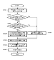
- FIG. 24 shows the processing procedure executed by the AP in the form of a flowchart in order to realize the communication sequence as shown in FIGS. 6, 10, 14, and 20.
- the illustrated processing procedure assumes that the communication device 200 having the device configuration shown in FIG. 2 executes as an AP. Further, here, it is assumed that communication is possible between AP and STA using two bands, band A and band B.
- the AP transmits the MBO cue setup signal to the subordinate STA and receives the MBO cue setup signal from the subordinate STA (step S2401).
- the AP determines whether to transmit the Data signal to the STA using both the bands A and B based on the MBO queue setup signal exchanged with the STA (step S2402).
- step S2402 if it is decided not to transmit the Data signal to the STA using both the bands A and B (No in step S2402), the AP acquires the transmission right in either band A or band B. Then (step S2413), data is fetched from the queue corresponding to the band for which the transmission right has been acquired (step S2414).
- the AP transmits the Data signal to the STA using both the bands A and B, or using either band for which the transmission right has been acquired (step S2405).
- the AP determines the data to be retransmitted and stores the data in the MBO queue 304 together with the information indicating the band in which the data was first transmitted. (Step S2407).
- the AP determines whether to retransmit the Data signal to the STA using both the bands A and B (step S2408).
- the AP acquires the transmission right in both the band A and the band B. (Step S2409). If it is determined not to retransmit the Data signal to the STA using both the bands A and B (No in step S2408), the AP is in a band other than the band in which the data to be retransmitted is first transmitted. Acquire the transmission right (step S2415).
- FIG. 25 shows the processing procedure executed by the STA in the form of a flowchart in order to realize the communication sequence as shown in FIGS. 6, 10, 14, and 20.
- the illustrated processing procedure assumes that the communication device 200 having the device configuration shown in FIG. 2 executes as STA. Further, here, it is assumed that communication is possible between AP and STA using two bands, band A and band B.
- the STA transmits the MBO queue setup signal to the connection destination AP and receives the MBO queue setup signal from the connection destination AP (step S2501).
- the STA waits for the reception of the Data signal in one or both bands of band A and band B based on the MBO queue setup signal exchanged with the AP. Then, the STA checks whether or not the Data signal is received from the AP at the same time in both the bands A and B (step S2502).
- the STA determines whether to transmit the reception result of the Data signal as one BA signal. (Step S2503).
- the STA is a BA signal including the reception result of the Data signal in each band and the information of the transmitted band. Is transmitted in one or more bands (step S2504).
- the STA when the STA normally receives the Data signal retransmitted from the AP (step S2505), the STA first receives the data from the identifier indicating the order added to each received data and the information indicating the first transmitted band. And the retransmission data are linked, the order is correctly rearranged, and the data is delivered to the upper layer (step S2506).
- the STA transmits the BA signal for the retransmitted Data signal to the AP (step S2507), and ends this process.
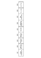
- FIG. 26 shows an example of a frame format in which the MBO queue setup signal is stored.
- the Queue Constitution indicated by reference number 2601 includes information on the queue configuration corresponding to AP and STA.
- the information regarding the queue configuration includes information regarding the presence / absence of the MBO queue, the data type (or access category) supported by the MBO queue, and the amount of data that the MBO queue can hold.
- Information about the queue configuration includes information about the number of queues corresponding to each band and the amount of data that can be held.
- the Band For ReTX Info indicated by the reference number 2602 includes information regarding the band for retransmitting data.
- the Band For TX Info indicated by the reference number 2603 includes information regarding the band for transmitting data.
- the Band For BA Info indicated by the reference number 2604 includes information regarding the band for notifying the reception result.
- the TID_INFO indicated by the reference number 2605 includes information regarding an identifier indicating the type of data to be transmitted / received.
- the Sequence Number Info indicated by the reference number 2606 includes information regarding an identifier indicating the order of data to be transmitted / received.
- the Relay Limit indicated by the reference number 2608 includes the maximum number of times of retransmission of the data to be transmitted / received.
- the Life Time indicated by the reference number 2609 includes information regarding the time until the data to be transmitted / received is discarded.
- band A and band B used for data communication between AP101 and STA102 is a band permitted to be used by database access, the use of that band is permitted by prior database access.
- a band usage permission flag indicating whether or not the data may be used may be included in the frame.
- FIG. 27 shows an example of a frame format used for transmitting a Data signal.
- the frame shown basically follows the format of a data frame that is common in wireless LAN systems that conform to the IEEE 802.11 standard. Since each field in the MAC header area shown by reference numbers 2701 to 2708 is general, detailed description thereof will be omitted here.
- the HT Control field indicated by the reference number 2709 is defined by IEEE802.11, and for example, control information specified in a higher standard intended for high throughput is described.
- the Total MBO Queue field indicated by the reference number 2721 and the Current MBO Queue field indicated by the reference number 2722 are included in the HT Control field.
- the Total MBO Queue field 2721 stores information about the amount of all data stored in the MBO queue. Further, in the Current MBO Queue field 2722, information regarding the amount of data stored in the sub queue in the MBO queue corresponding to the data type (access category) of the retransmission data is stored.
- the Total MBO Queue field 2721 and the Current MBO Queue field 2722 are included in the HT Control field 2709, but may be included in the MAC header.
- the Data signal is stored in the Frame Body indicated by the reference number 2710. Then, in the last FCS (Frame Check Sequence) field indicated by the reference number 2711, the CRC (Cyclic Redundancy Code) value calculated for the entire frame including the MAC header is described.
- FCS Frae Check Sequence
- CRC Cyclic Redundancy Code
- the techniques disclosed herein can be applied, for example, to communication systems conforming to the IEEE 802.11 standard, but of course can also be applied to various types of multi-band communication systems conforming to other wireless standards. Is possible.
- the embodiment to which the technique disclosed in the present specification is applied in data retransmission during downlink communication from the base station to the slave unit has been mainly described, but of course, from the slave unit to the base station.
- the techniques disclosed in the present specification can be applied to the case where the uplink communication and the side link communication between terminals are carried out using a plurality of bands.
- the technology disclosed in this specification can also have the following configuration.
- a communication device that transmits data in a plurality of bands.
- a first queue for each band that stores data to be transmitted in each band,
- a second queue common to at least two of the plurality of bands that stores data to be transmitted with high priority, and
- a control unit that controls transmission of data stored in the first queue and the second queue, and
- a communication device comprising.
- the control unit controls the transmission of information regarding the first queue and the second queue.
- the communication device according to claim 1.
- the control unit further controls the reception of information regarding the first queue and the second queue from the data transmission destination.
- the communication device according to (2) above.
- the first queue and the second queue each include a plurality of sub-queues for each data type.
- the communication device according to any one of (1) and (2) above.
- the information regarding the first queue and the second queue corresponds to the information regarding the presence or absence of the second queue and the second queue (or each sub-queue included in the second queue). Includes information about the type of data to be generated, information about the configuration of the second queue, including at least one of information about the amount of data that the second queue can hold.
- the information regarding the first queue and the second queue includes information about a band for retransmitting data, information about a band for transmitting data, information about a band for notifying a reception result, and transmission / reception. At least one of information about an identifier indicating the type of data to be transmitted, an identifier indicating the order of data to be transmitted, an identifier indicating the priority of data to be transmitted / received, the maximum number of times of retransmission of data to be transmitted / received, and the time until the data to be transmitted / received is discarded. Including one more The communication device according to (6) above.
- Data transmitted with high priority includes data that requires low delay and high reliability.
- the communication device according to any one of (1) to (6) above.
- Data transmitted with high priority includes retransmission data.
- the communication device according to any one of (1) to (7) above.
- the control unit controls the retransmission data output from the second queue to be transmitted by adding information regarding the band initially transmitted.
- the communication device according to (9) above.
- the control unit transmits the retransmission data output from the second queue using a band determined based on the band initially transmitted.
- the communication device according to any one of (9) and (10) above.
- the control unit simultaneously transmits the retransmission data output from the second queue in one or more bands including a band different from the band initially transmitted.
- the communication device according to (11) above.
- the control unit adds information on the amount of data stored in the second queue to the retransmission data output from the second queue and transmits the data.
- the communication device according to any one of (8) to (13) above.
- the information regarding the amount of data stored in the second queue includes information regarding the amount of all data stored in the second queue.
- At least one of the plurality of bands is a band permitted to be used by database access.
- the communication device according to any one of (1) to (16) above.
- a communication method for transmitting data in a plurality of bands A step of storing the data to be transmitted in each band in the first queue for each band, The step of transmitting the data stored in the first queue and A step of storing data to be transmitted with high priority in a second queue common to at least two of the plurality of bands, and The step of transmitting the data stored in the second queue and Communication method with.
- a communication device that receives data in a plurality of bands.
- An information receiving unit that receives information about a first queue for each band and a second queue common to at least two of the plurality of bands.
- a data receiving unit that receives data in which information indicating the order and information indicating the first transmitted band are added to at least one of the plurality of bands.
- a communication device comprising.
- the information receiving unit receives information regarding the presence or absence of the second queue as the information regarding the first queue for each band and the second queue common to at least two of the plurality of bands.
- the second queue (or each sub-queue included in the second queue) receives at least one of the corresponding data type information and the amount of data that the second queue can hold.
- the information regarding the first queue for each band and at least two common second queues among the plurality of bands is the data regarding the first queue and the information regarding the second queue.
- Information about the band for retransmitting information about the band for transmitting data, information about the band for notifying the reception result, identifier indicating the type of data to be transmitted / received, identifier indicating the order of data to be transmitted, priority of data to be transmitted / received. It further includes at least one of information about the degree identifier, the maximum number of times the data to be sent and received is retransmitted, and the time until the data to be sent and received is discarded.
- the transmitting unit transmits the reception result in the band specified by the information received by the information receiving unit.
- the communication device according to (22) above.
- the data receiving unit receives the data to which information regarding the amount of data stored in the second queue is further added.
- the communication device according to any one of (19) to (23) above.
- the second queue includes a plurality of sub queues for each data type.
- the information regarding the amount of data stored in the second queue includes information regarding the amount of data stored in the sub-queue in the second queue corresponding to the data type of the retransmission data.
- At least one of the plurality of bands is a band permitted to be used by database access.
- the communication device according to any one of (19) to (26) above.
- a communication method for receiving data in a plurality of bands A step of receiving information about a first queue for each band and a second queue common to at least two of the plurality of bands. A step of receiving data in which information indicating the order and information indicating the first transmitted band are added to at least one of the plurality of bands. Communication method with.
Landscapes
- Engineering & Computer Science (AREA)
- Computer Networks & Wireless Communication (AREA)
- Signal Processing (AREA)
- Mobile Radio Communication Systems (AREA)
Abstract
Priority Applications (3)
| Application Number | Priority Date | Filing Date | Title |
|---|---|---|---|
| EP20794994.2A EP3962205A4 (fr) | 2019-04-23 | 2020-02-27 | Dispositif de communication et procédé de communication |
| US17/603,764 US12238582B2 (en) | 2019-04-23 | 2020-02-27 | Communication device and communication method |
| CN202080028994.1A CN113692766A (zh) | 2019-04-23 | 2020-02-27 | 通信设备和通信方法 |
Applications Claiming Priority (2)
| Application Number | Priority Date | Filing Date | Title |
|---|---|---|---|
| JP2019082358 | 2019-04-23 | ||
| JP2019-082358 | 2019-04-23 |
Publications (1)
| Publication Number | Publication Date |
|---|---|
| WO2020217704A1 true WO2020217704A1 (fr) | 2020-10-29 |
Family
ID=72942391
Family Applications (1)
| Application Number | Title | Priority Date | Filing Date |
|---|---|---|---|
| PCT/JP2020/008112 Ceased WO2020217704A1 (fr) | 2019-04-23 | 2020-02-27 | Dispositif de communication et procédé de communication |
Country Status (5)
| Country | Link |
|---|---|
| US (1) | US12238582B2 (fr) |
| EP (1) | EP3962205A4 (fr) |
| CN (1) | CN113692766A (fr) |
| TW (1) | TWI831961B (fr) |
| WO (1) | WO2020217704A1 (fr) |
Cited By (1)
| Publication number | Priority date | Publication date | Assignee | Title |
|---|---|---|---|---|
| WO2023033184A1 (fr) * | 2021-09-06 | 2023-03-09 | シャープ株式会社 | Dispositif de communication et procédé de communication |
Families Citing this family (3)
| Publication number | Priority date | Publication date | Assignee | Title |
|---|---|---|---|---|
| KR20250142290A (ko) * | 2023-03-31 | 2025-09-30 | 지티이 코포레이션 | 다운링크 및 업링크 송신을 위한 대역폭 부스팅 |
| US20240349328A1 (en) * | 2023-04-13 | 2024-10-17 | Charter Communications Operating, Llc | Communication scheduling in a network based on different qos |
| CN120835333B (zh) * | 2025-07-11 | 2026-03-24 | 北京互联时代移动通信有限公司 | 基于物联网通信基站的多频段自适应切换方法 |
Citations (5)
| Publication number | Priority date | Publication date | Assignee | Title |
|---|---|---|---|---|
| JP2008053829A (ja) * | 2006-08-22 | 2008-03-06 | Toshiba Corp | 無線通信装置及び無線通信方法 |
| US20150282005A1 (en) * | 2014-03-28 | 2015-10-01 | Qualcomm Incorporated | Link aggregation in wireless local area networks |
| JP2016040945A (ja) * | 2011-04-04 | 2016-03-24 | クアルコム,インコーポレイテッド | ホワイトスペース内通信のためのシステムおよび方法 |
| US20180278697A1 (en) * | 2017-03-27 | 2018-09-27 | Intel IP Corporation | [5g next generation wi-fi] on the fly traffic steering for collocated multi-band aggregation |
| JP2018157535A (ja) | 2017-03-15 | 2018-10-04 | 株式会社国際電気通信基礎技術研究所 | 無線通信装置および無線通信方法 |
Family Cites Families (20)
| Publication number | Priority date | Publication date | Assignee | Title |
|---|---|---|---|---|
| US7640373B2 (en) * | 2003-04-25 | 2009-12-29 | Motorola, Inc. | Method and apparatus for channel quality feedback within a communication system |
| US7450512B1 (en) | 2003-07-29 | 2008-11-11 | Rockwell Collins, Inc. | Recirculating retransmission queuing system and method |
| US10469205B2 (en) * | 2005-07-27 | 2019-11-05 | T-Mobile Usa, Inc. | Application-based multi-band transmission |
| KR20090118074A (ko) | 2007-03-01 | 2009-11-17 | 가부시키가이샤 엔티티 도코모 | 기지국장치 및 통신제어방법 |
| US8442531B2 (en) * | 2007-05-15 | 2013-05-14 | Nokia Corporation | Context transfers and multi-band operation for wireless networks |
| KR101479011B1 (ko) * | 2008-12-17 | 2015-01-13 | 삼성전자주식회사 | 다중 대역 스케쥴링 방법 및 이를 이용한 방송 서비스 시스템 |
| US9007968B2 (en) * | 2009-06-16 | 2015-04-14 | Samsung Electronics Co., Ltd. | System and method for wireless multi-band networks association and maintenance |
| US8737415B2 (en) * | 2010-07-02 | 2014-05-27 | Telefonaktiebolaget L M Ericsson (Publ) | Prioritization of data packets |
| US9467885B2 (en) * | 2010-11-08 | 2016-10-11 | Qualcomm Incorporated | Inter-frequency measurement control in a multi-carrier system |
| US20140269468A1 (en) * | 2013-03-14 | 2014-09-18 | Qualcomm Incorporated | Systems and methods for wireless band switching |
| FR3014631B1 (fr) * | 2013-12-06 | 2017-03-31 | Sagemcom Broadband Sas | Dispositif et procede de configuration d'un dispositif de communication |
| US9668088B2 (en) * | 2014-04-28 | 2017-05-30 | Dell Products, Lp | Dynamic spectrum sharing for wireless local area networks |
| US9538535B2 (en) * | 2015-05-11 | 2017-01-03 | Qualcomm Incorporated | Cross-band rate adaption |
| US11005635B2 (en) | 2015-09-22 | 2021-05-11 | Qualcomm Incorporated | Reliable channel assisted hybrid-arq |
| US10230654B2 (en) * | 2016-12-28 | 2019-03-12 | Intel IP Corporation | Multiband aggregation data encapsulation |
| GB201704216D0 (en) * | 2017-03-16 | 2017-05-03 | Ranplan Wireless Network Design Ltd | WIFI multi-band fingerprint-based indoor positioning |
| WO2019055062A1 (fr) * | 2017-09-15 | 2019-03-21 | Intel Corporation | Dispositif de transmission et de réception sur un fil de cuivre installé dans un local d'abonné |
| CN110300337A (zh) * | 2018-03-21 | 2019-10-01 | 华为技术有限公司 | 无线保真链路重传报文的方法和装置 |
| US11632817B2 (en) * | 2018-08-10 | 2023-04-18 | Lg Electronics Inc. | Method and device for transmitting information for operating station in wireless local area network system supporting multiple bands |
| US11330625B2 (en) * | 2019-03-11 | 2022-05-10 | Intel Corporation | Multi-band bandwidth query report (MB-BQR) signaling in extremely high throughput (EHT) systems |
-
2020
- 2020-02-27 US US17/603,764 patent/US12238582B2/en active Active
- 2020-02-27 CN CN202080028994.1A patent/CN113692766A/zh not_active Withdrawn
- 2020-02-27 WO PCT/JP2020/008112 patent/WO2020217704A1/fr not_active Ceased
- 2020-02-27 EP EP20794994.2A patent/EP3962205A4/fr not_active Withdrawn
- 2020-04-13 TW TW109112331A patent/TWI831961B/zh active
Patent Citations (5)
| Publication number | Priority date | Publication date | Assignee | Title |
|---|---|---|---|---|
| JP2008053829A (ja) * | 2006-08-22 | 2008-03-06 | Toshiba Corp | 無線通信装置及び無線通信方法 |
| JP2016040945A (ja) * | 2011-04-04 | 2016-03-24 | クアルコム,インコーポレイテッド | ホワイトスペース内通信のためのシステムおよび方法 |
| US20150282005A1 (en) * | 2014-03-28 | 2015-10-01 | Qualcomm Incorporated | Link aggregation in wireless local area networks |
| JP2018157535A (ja) | 2017-03-15 | 2018-10-04 | 株式会社国際電気通信基礎技術研究所 | 無線通信装置および無線通信方法 |
| US20180278697A1 (en) * | 2017-03-27 | 2018-09-27 | Intel IP Corporation | [5g next generation wi-fi] on the fly traffic steering for collocated multi-band aggregation |
Non-Patent Citations (1)
| Title |
|---|
| See also references of EP3962205A4 |
Cited By (1)
| Publication number | Priority date | Publication date | Assignee | Title |
|---|---|---|---|---|
| WO2023033184A1 (fr) * | 2021-09-06 | 2023-03-09 | シャープ株式会社 | Dispositif de communication et procédé de communication |
Also Published As
| Publication number | Publication date |
|---|---|
| CN113692766A (zh) | 2021-11-23 |
| US20220182884A1 (en) | 2022-06-09 |
| EP3962205A1 (fr) | 2022-03-02 |
| TW202046669A (zh) | 2020-12-16 |
| TWI831961B (zh) | 2024-02-11 |
| US12238582B2 (en) | 2025-02-25 |
| EP3962205A4 (fr) | 2022-10-12 |
Similar Documents
| Publication | Publication Date | Title |
|---|---|---|
| US12199787B2 (en) | Wireless communication device | |
| US10903891B2 (en) | Communication apparatus, communication method, and communication system | |
| KR100999823B1 (ko) | Mmr 확장된 802.16e 시스템을 위한 중앙집중식 스케줄러 중계국 | |
| US8515437B2 (en) | Wireless resource allocation method, wireless mobile station and wireless base station in wireless communication system | |
| TWI831961B (zh) | 通訊裝置及通訊方法 | |
| EP3962201A1 (fr) | Procédé et dispositif de transmission de données de liaison descendante, et support de stockage | |
| JP6335205B2 (ja) | 無線通信装置および無線通信方法 | |
| Swamy et al. | Network coding for high-reliability low-latency wireless control | |
| US20120250606A1 (en) | Enabling simultaneous transmissions in wireless network | |
| JP2023553174A (ja) | 送信手順に関与するntnエンティティ、ユーザ機器、および基地局 | |
| JP2025062115A (ja) | 通信装置及び通信方法 | |
| JP2021040172A (ja) | 無線通信装置 | |
| US12335155B2 (en) | Method for operating one or more nodes in a communications network for coordinating transmissions of different nodes in the network using data validity as decision metric | |
| US20140064085A1 (en) | Communication node and communication method | |
| WO2017151849A1 (fr) | Signalisation de commande pour scénarios de relais | |
| US12568400B2 (en) | Communication apparatus and communication method for cooperative transmission between a plurality of access points | |
| US12413378B1 (en) | Systems and methods for variable time division duplex data allocation | |
| US12075285B2 (en) | Wireless communication system, and wireless communication method | |
| US20240349396A1 (en) | Method and apparatus for drx-based sidelink communication | |
| Kosek-Szott et al. | CLF-MAC: A coordinated MAC protocol supporting lossy forwarding in WLANs |
Legal Events
| Date | Code | Title | Description |
|---|---|---|---|
| 121 | Ep: the epo has been informed by wipo that ep was designated in this application |
Ref document number: 20794994 Country of ref document: EP Kind code of ref document: A1 |
|
| NENP | Non-entry into the national phase |
Ref country code: DE |
|
| ENP | Entry into the national phase |
Ref document number: 2020794994 Country of ref document: EP Effective date: 20211123 |
|
| NENP | Non-entry into the national phase |
Ref country code: JP |
|
| WWG | Wipo information: grant in national office |
Ref document number: 17603764 Country of ref document: US |
|
| WWW | Wipo information: withdrawn in national office |
Ref document number: 2020794994 Country of ref document: EP |
|
| WWW | Wipo information: withdrawn in national office |
Ref document number: 2021129498 Country of ref document: RU |