WO2020217745A1 - Article absorbant et stratifié de tissu non tissé - Google Patents
Article absorbant et stratifié de tissu non tissé Download PDFInfo
- Publication number
- WO2020217745A1 WO2020217745A1 PCT/JP2020/010083 JP2020010083W WO2020217745A1 WO 2020217745 A1 WO2020217745 A1 WO 2020217745A1 JP 2020010083 W JP2020010083 W JP 2020010083W WO 2020217745 A1 WO2020217745 A1 WO 2020217745A1
- Authority
- WO
- WIPO (PCT)
- Prior art keywords
- woven fabric
- absorbent article
- welded portion
- openings
- opening
- Prior art date
- Legal status (The legal status is an assumption and is not a legal conclusion. Google has not performed a legal analysis and makes no representation as to the accuracy of the status listed.)
- Ceased
Links
Images





Classifications
-
- A—HUMAN NECESSITIES
- A61—MEDICAL OR VETERINARY SCIENCE; HYGIENE
- A61F—FILTERS IMPLANTABLE INTO BLOOD VESSELS; PROSTHESES; DEVICES PROVIDING PATENCY TO, OR PREVENTING COLLAPSING OF, TUBULAR STRUCTURES OF THE BODY, e.g. STENTS; ORTHOPAEDIC, NURSING OR CONTRACEPTIVE DEVICES; FOMENTATION; TREATMENT OR PROTECTION OF EYES OR EARS; BANDAGES, DRESSINGS OR ABSORBENT PADS; FIRST-AID KITS
- A61F13/00—Bandages or dressings; Absorbent pads
- A61F13/15—Absorbent pads, e.g. sanitary towels, swabs or tampons for external or internal application to the body; Supporting or fastening means therefor; Tampon applicators
- A61F13/45—Absorbent pads, e.g. sanitary towels, swabs or tampons for external or internal application to the body; Supporting or fastening means therefor; Tampon applicators characterised by the shape
- A61F13/49—Absorbent pads, e.g. sanitary towels, swabs or tampons for external or internal application to the body; Supporting or fastening means therefor; Tampon applicators characterised by the shape specially adapted to be worn around the waist, e.g. diapers, nappies
-
- A—HUMAN NECESSITIES
- A61—MEDICAL OR VETERINARY SCIENCE; HYGIENE
- A61F—FILTERS IMPLANTABLE INTO BLOOD VESSELS; PROSTHESES; DEVICES PROVIDING PATENCY TO, OR PREVENTING COLLAPSING OF, TUBULAR STRUCTURES OF THE BODY, e.g. STENTS; ORTHOPAEDIC, NURSING OR CONTRACEPTIVE DEVICES; FOMENTATION; TREATMENT OR PROTECTION OF EYES OR EARS; BANDAGES, DRESSINGS OR ABSORBENT PADS; FIRST-AID KITS
- A61F13/00—Bandages or dressings; Absorbent pads
- A61F13/15—Absorbent pads, e.g. sanitary towels, swabs or tampons for external or internal application to the body; Supporting or fastening means therefor; Tampon applicators
- A61F13/51—Absorbent pads, e.g. sanitary towels, swabs or tampons for external or internal application to the body; Supporting or fastening means therefor; Tampon applicators characterised by the outer layers of the pads
Definitions
- the present invention relates to an absorbent article and a non-woven fabric laminate.
- Disposable diapers are known as an example of absorbent articles that absorb excrement such as urine. Further, as a waist member or a leg member of a disposable diaper, a sheet member to which elasticity is given by attaching an elastic member with an adhesive such as a hot melt adhesive is generally used.
- Patent Document 1 a perforated non-woven fabric provided with a large number of holes penetrating the front and back and a support sheet laminated with the perforated non-woven fabric are adhered to each other in a predetermined adhesive region via a hot melt adhesive.
- a disposable non-woven fabric article to which a hot melt adhesive is not applied is disclosed on the central side of the adhesive region from the peripheral edge of the region overlapping each hole.
- the present invention has been made in view of the above-mentioned conventional problems, and an object of the present invention is that when an elastic member is joined between sheet members including a perforated non-woven fabric, an adhesive is released from the perforation. It is an object of the present invention to provide an absorbent article that prevents the elastic member from being displaced or coming off while suppressing the possibility of seepage.
- the main invention for achieving the above object is An absorbent main body that has a vertical direction, a horizontal direction, and a front-rear direction that intersect with each other and absorbs liquid, a ventral waistline portion provided along the left-right direction, and a back provided along the left-right direction.
- An absorbent article including a side waist circumference portion, wherein at least one waist circumference portion of the ventral waist circumference portion and the dorsal waist circumference portion has a first nonwoven fabric having a plurality of openings, a second nonwoven fabric, and the above. It has an elastic member provided between the first non-woven fabric and the second non-woven fabric and expandable along the left-right direction, and the elastic member has a non-applied portion to which no adhesive is applied.
- It has an upper welded portion and a lower welded portion for welding the first nonwoven fabric and the second nonwoven fabric, and the upper welded portion is provided above the non-coated portion in the vertical direction, and the lower side of the non-coated portion. Is provided with the lower welded portion, and the edge portion of the first non-woven fabric adjacent to a certain of the plurality of openings is formed with at least a part of the upper welded portion or the lower welded portion. It is an absorbent article characterized by overlapping.
- the absorbency prevents the elastic member from being displaced or coming off while suppressing the possibility of adhesive oozing out from the perforation. Can provide goods.
- FIG. 1 is a schematic perspective view of the diaper 1.
- FIG. 2 is a schematic plan view of the unfolded and stretched diaper 1 as viewed from the skin side of the wearer.
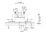
- FIG. 3 is a cross-sectional view taken along the line AA in FIG.
- FIG. 4 is a schematic plan view of the ventral waist circumference 31 in the expanded and extended state as viewed from the non-skin side.
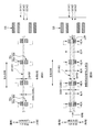
- 5A and 5B are explanatory views of the attachment function of the elastic member 35, and is a schematic enlarged view of a portion C in FIG.
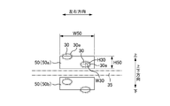
- FIG. 6 is an enlarged view of the region X of FIG. 4, and is a diagram for explaining the positional relationship between the welded portion 50 and the opening 30 in a state of being extended in the left-right direction.
- FIG. 7 is a schematic view showing an example of the opening 30.
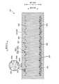
- FIG. 8 is a schematic plan view of the nonwoven fabric laminate 100.
- FIG. 9 is a schematic plan view of the ventral waist circumference 31'in the expanded and extended state according to the other embodiment as viewed from the non-skin side.
- An absorbent main body that has a vertical direction, a horizontal direction, and a front-rear direction that intersect with each other and absorbs liquid, a ventral waistline portion provided along the left-right direction, and a back provided along the left-right direction.
- An absorbent article including a side waist circumference portion, wherein at least one waist circumference portion of the ventral waist circumference portion and the dorsal waist circumference portion has a first nonwoven fabric having a plurality of openings, a second nonwoven fabric, and the above.
- It has an elastic member provided between the first non-woven fabric and the second non-woven fabric and expandable along the left-right direction, and the elastic member has a non-applied portion to which no adhesive is applied. It has an upper welded portion and a lower welded portion for welding the first nonwoven fabric and the second nonwoven fabric, and the upper welded portion is provided above the non-coated portion in the vertical direction, and the lower side of the non-coated portion. Is provided with the lower welded portion, and the edge portion of the first non-woven fabric adjacent to a certain of the plurality of openings is formed with at least a part of the upper welded portion or the lower welded portion. It is an absorbent article characterized by overlapping.
- the elastic member provided between the first and second non-woven fabrics is provided with a non-applied portion to which an adhesive such as a hot melt adhesive is not applied, so that the first having a hole is formed. It is possible to suppress the risk of adhesive or the like seeping out from the openings of the non-woven fabric.
- an upper welding portion and a lower welding portion that regulate the vertical position of the non-coated portion are provided. In such a configuration, if the perforation edge portion, which has a high density due to the fibers existing in the perforation portion being gathered together, overlaps with the upper or lower welding portion, the first and second non-woven fabrics are formed. The welding strength (strength of the welded portion) between the two becomes stronger, and the position of the elastic member in the vertical direction can be firmly regulated.
- the non-coated portion is sandwiched between the upper welded portion and the lower welded portion in a state of being contracted in the left-right direction, whereby the first nonwoven fabric and the second nonwoven fabric are sandwiched. It is desirable that it is attached to.
- the vertical position of the non-coated portion can be tightly regulated, and the non-coated portion can be attached to the first non-woven fabric and the second non-woven fabric.
- the length of the upper welded portion or the lower welded portion in the vertical direction of the absorbent article is longer than the diameter of the opening.
- the length of the upper welded portion or the lower welded portion in the left-right direction of the absorbent article is longer than the diameter of the opening.
- the plurality of openings have a first opening and a second opening, and the first opening is a first opening adjacent to the first opening.
- the second opening has a second edge adjacent to the second opening, and the upper welded portion or the lower welded portion is the first edge portion. And it is desirable to have an overlapping portion that overlaps with the second edge portion.
- the edge portion which is a region where the density is increased due to the fibers being gathered together, overlaps more with the welded portion, so that the bonding by the welded portion becomes stronger.
- the elastic member can be attached more firmly.
- the upper welded portion and the lower welded portion are each horizontally long along the left-right direction, and the plurality of openings are each horizontally long along the left-right direction. Is desirable.
- the shape of the welded portion is made horizontally long along the left-right direction to prevent the elastic members from being displaced. Further, when the shape of the opening is also horizontally long along the left-right direction, the fiber existing in the opening portion is gathered and the region where the high-density opening edge portion and the welded portion overlap is lengthened in the left-right direction. Since it can be provided, more strong welded portions can be formed along the left-right direction. As a result, it is possible to make it difficult for the elastic member that easily comes off in the left-right direction to come off.
- the length from the lower end of the upper welded portion to the upper end of the lower welded portion is the same as the length of the opening in the vertical direction, or the length of the opening in the vertical direction. It is desirable that it is shorter than the length.
- the strength of the upper and lower welds is increased by overlapping both the upper and lower welds with the perforated edge where the fibers are gathered together to increase the density. Become strong. As a result, the positions of the elastic members provided between the upper and lower welded portions are less likely to shift.
- a plurality of the upper welded portion and the lower welded portion are provided at least one of the ventral waist circumference portion and the dorsal waist circumference portion at intervals in the left-right direction. It is desirable that at least one of the plurality of openings is present between the two upper welding portions or the lower welding portions adjacent to each other in the left-right direction.
- the length of the upper welded portion or the lower welded portion in the left-right direction is longer than the distance between the openings adjacent to each other in the left-right direction among the plurality of openings. Is desirable.
- the upper welded portion and the lower welded portion are spaced apart from each other in the left-right direction or the vertical direction in at least one of the ventral waist circumference portion and the dorsal waist circumference portion.
- the number of openings that do not overlap with either the upper welding portion or the lower welding portion that are provided is the number of the openings that are provided in the plurality of holes. , It is desirable that the number of holes is larger than the number of openings that at least partially overlap with any of the upper welded portion and the lower welded portion provided.
- At least one of the ventral girth portion and the dorsal girth portion is provided with a plurality of girth portions at intervals in the left-right direction or the up-down direction, the upper welded portion and the lower side. It has a welded portion and an opening row having a plurality of openings arranged adjacent to each other in the vertical direction or the left-right direction, and the open row is provided with a plurality of the upper welded portion and the lower welded portion. It is desirable to have only openings that do not overlap with any of the above.
- the visibility of the holes is improved because the rows of holes do not overlap with any of the welded parts.
- a non-woven fabric laminate having a first non-woven fabric having a plurality of openings, a second non-woven fabric, and a stretchable elastic member provided between the first non-woven fabric and the second non-woven fabric, wherein the non-woven fabric has the elasticity.
- the member has a non-coated portion to which no adhesive is applied, has a one-side welded portion for welding the first non-woven fabric and the second non-woven fabric, and the other-side welded portion, and is orthogonal to the longitudinal direction of the elastic member.
- the one-sided welded portion is provided on one side of the non-coated portion
- the other-side welded portion is provided on the other side of the non-coated portion
- the plurality of open parts of the first non-woven fabric are provided.
- the edge portion of the hole adjacent to the opening is a non-woven fabric laminate characterized in that it overlaps with at least a part of the one-side welded portion or the other-side welded portion.
- the elastic member provided between the first and second non-woven fabrics is provided with a non-coated portion to which a hot melt adhesive or the like is not applied, so that the first non-woven fabric has holes. It is possible to suppress the risk of adhesive or the like seeping out from the holes.
- the non-coated portion tends to shift in the orthogonal direction orthogonal to the longitudinal direction of the elastic member, one-side welded portion and the other-side welded portion that regulate the position of the non-coated portion in the orthogonal direction are provided.
- the welding strength between the first and second nonwoven fabrics (strength of the welding portion). Becomes stronger and can tightly regulate the position of the rubber thread in the orthogonal direction.
- a pants-type disposable diaper 1 for infants (hereinafter, also referred to as “diaper 1”) will be described as an example.
- the present invention is not limited to the above, and the absorbent article according to the present invention can also be applied to disposable diapers for adults, tape-type disposable diapers, shorts-type sanitary napkins, and the like.
- FIG. 1 is a schematic perspective view of the diaper 1.
- FIG. 2 is a schematic plan view of the unfolded and stretched diaper 1 as viewed from the skin side of the wearer.
- FIG. 3 is a cross-sectional view taken along the line AA in FIG. 2, and is also a cross-sectional view taken along the line BB in FIG.
- the diaper 1 In the pants-shaped state before wearing as shown in FIG. 1, the diaper 1 has a "vertical direction", a “horizontal direction” orthogonal to the vertical direction, and a “front-back direction” orthogonal to the vertical direction and the horizontal direction.
- the upper side corresponds to the waist opening side of the wearer
- the lower side corresponds to the inseam side of the wearer.
- the front side corresponds to the ventral side of the wearer
- the rear side corresponds to the back side of the wearer.
- the diaper 1 has a ventral waist circumference 31 provided along the left-right direction and a dorsal portion provided along the left-right direction while being located behind the ventral waist circumference 31. It includes a side girth portion 41 and an absorbent main body 10 provided as a lower crotch between the ventral girth portion 31 and the dorsal girth portion 41 while absorbing liquid.
- the ventral waist circumference 31 and the dorsal waist circumference 41 jointly form a waist circumference opening BH on the upper side in the vertical direction.
- the absorbent main body 10 is located so as to project downward in the vertical direction from the ventral waist circumference 31 and the dorsal waist circumference 41.
- the left and right end portions 31e and 31e of the ventral waist circumference 31 and the left and right end portions 41e and 41e of the corresponding dorsal waist circumference 41 are joined by a side seal portion SS as a welding portion. ing.
- the ventral waist circumference 31 and the dorsal waist circumference 41 form leg circumference openings LH and LH on both sides in the lower and left-right directions in cooperation with the absorbent main body 10. ..
- the "deployed state” means that the ventral waist circumference portion 31 and the dorsal waist circumference portion 41 are formed by breaking the joint of the side seal portions SS that the diaper 1 in the pants-shaped state of FIG. 1 has on both sides in the left-right direction.
- This is a state in which the diaper 1 is unfolded on a plane by separating the diaper 1 and opening the diaper 1 in the vertical direction.
- the “extended state” is a state in which the product (diaper 1) is extended without wrinkles, specifically, each member (for example, the absorbent body 10 and the ventral waist circumference 31) constituting the diaper 1. It refers to a state in which the dimensions are extended until the dimensions match or are close to the dimensions of the individual member.
- the diaper 1 In the unfolded state, the diaper 1 has a longitudinal direction, a left-right direction, and a thickness direction (direction penetrating the paper surface in FIG. 2) as three directions orthogonal to each other.
- the longitudinal direction is along the above-mentioned vertical direction.
- one side in the longitudinal direction corresponds to the ventral side (front side), and the other side corresponds to the dorsal side (rear side).
- the outer side in the longitudinal direction corresponds to the upper side in the vertical direction (girth opening side)
- the inner side in the longitudinal direction corresponds to the lower side in the vertical direction (inseam side).
- the vertical direction may be used instead of the longitudinal direction even in this expanded state.
- the left-right direction is synonymous with the left-right direction in the above-mentioned pants type state.
- one side corresponds to the skin side in contact with the wearer's body, and the other side corresponds to the non-skin side on the opposite side.
- the ventral waist circumference 31 is arranged along the left-right direction, and the dorsal waist circumference 41 is positioned at a predetermined distance from the ventral waist circumference 31 in the longitudinal direction. And it is arranged along the left and right direction. Then, while the absorbent main body 10 is hung between the ventral waist circumference portion 31 and the dorsal waist circumference portion 41 along the longitudinal direction, each end portion 10ea, 10eb (that is, that is, the absorbent main body 10 in the longitudinal direction). , The front upper end 10ea and the rear upper end 10eb) in the pants-shaped state are joined and fixed to the nearest waist circumferences 31 and 41, respectively, whereby the appearance shape is substantially H-shaped in plan view.
- the diaper 1 is folded in half with the predetermined position CL1 in the longitudinal direction (the center position CL1 of the diaper 1 in the longitudinal direction) in the absorbent body 10 as the folding position, and the diapers 1 face each other in this folded state.
- the waist circumferences 31 and 41 are connected in an annular shape, thereby as shown in FIG.
- This is a pants-type diaper 1 in which a waist opening BH and a pair of leg openings LH and LH are formed.
- the absorbent body 10 has a substantially rectangular shape in a plan view in the expanded state shown in FIG.
- the longitudinal direction of the absorbent body 10 is arranged along the longitudinal direction of the diaper 1.
- the absorbent main body 10 is absorbed by the absorbent body 11 and the liquid-permeable top sheet 13 that covers the absorbent body 11 from the skin side to form the skin side surface of the absorbent main body 10.
- It is provided with a liquid-impermeable back sheet 15 that covers the body 11 from the non-skin side and forms a non-skin side surface of the absorbent main body 10.
- the absorber 11 has a liquid-absorbing absorbent core 11c and a core wrap sheet (not shown) that covers the outer peripheral surface of the core 11c.
- the absorbent core 11c is a molded body obtained by molding a liquid absorbent material such as pulp fiber or a highly absorbent polymer into a substantially hourglass shape in a plan view as an example of a predetermined shape.
- a liquid-permeable sheet such as tissue paper or non-woven fabric can be used as the core wrap sheet, but the core wrap sheet may not be used.
- the shape of the absorbent core 11c is not limited to the above-mentioned substantially hourglass shape in a plan view, and may be any other shape.
- the top sheet 13 is a liquid-permeable flexible sheet such as a non-woven fabric.
- the back sheet 15 is a liquid-impermeable and flexible sheet.
- a two-layer having a liquid-impermeable leak-proof sheet such as a polyethylene film or a polypropylene film and a non-woven fabric exterior sheet bonded to the non-skin side of the leak-proof sheet.
- a laminated sheet of structure can be mentioned.
- At least the back sheet 15 is a flat-sized sheet that protrudes from the absorber 11 in the longitudinal direction and the left-right direction. Then, leg gather LGs that expand and contract in the longitudinal direction are formed in the portions protruding in the left-right direction. That is, a thread rubber 17 along the longitudinal direction is fixed to the protruding portion as an elastic member in a state of being extended in the longitudinal direction, whereby an elastic leg gather LG is formed in the portion. ..
- the absorbent main body 10 has three-dimensional gathers LSG and LSG as leak-proof wall portions at each end in the left-right direction for the purpose of preventing lateral leakage. That is, a structure in which the thread rubber 18 along the longitudinal direction is attached as an elastic member to the sheet-like portion to be the three-dimensional gather LSG in a state of being extended in the longitudinal direction is provided at each end of the absorbent body 10 in the left-right direction. ing.
- the ventral waist circumference 31 is a sheet-like member having a substantially rectangular shape in a plan view and having a first non-woven fabric 32 and a second non-woven fabric 33 laminated in the thickness direction.
- the first non-woven fabric 32 has a plurality of openings 30 (FIG. 1 and the like), and is arranged on the non-skin side of the second non-woven fabric 33 in the thickness direction as shown in FIG.
- the first non-woven fabric 32 and the second non-woven fabric 33 are in a state of being overlapped with each other in the thickness direction, and the pair of facing surfaces facing each other are in the vertical and horizontal directions as shown in FIG. 4 described later.
- the ventral waist circumference portion 31 is arranged so as to project to both sides in the left-right direction from the absorbent main body 10, and the ventral end portion (front upper end) of the absorbent main body 10 is provided. Part) 10ea is overlapped and joined from the non-skin side.
- the dorsal waist circumference portion 41 is also a sheet-like member having a substantially rectangular shape in a plan view having a first non-woven fabric 42 and a second non-woven fabric 43 laminated in the thickness direction, similarly to the ventral side waist circumference portion 31.
- the first nonwoven fabric 42 has a plurality of openings 30 (not shown) and is arranged on the non-skin side of the second nonwoven fabric 43 in the thickness direction as shown in FIG. Then, the first nonwoven fabric 42 and the second nonwoven fabric 43 are in a state of being overlapped with each other in the thickness direction, and the pair of facing surfaces facing each other are the same as in the case of the ventral waist circumference portion 31 of FIG.
- the dorsal waist circumference portion 41 is arranged so as to project from the absorbent main body 10 to both sides in the left-right direction, and the dorsal end portion (rear side) of the absorbent main body 10 is provided.
- Upper end) 10 eb is overlapped and joined from the non-skin side.
- both the first nonwoven fabric 32 on the ventral waist circumference 31 side and the first nonwoven fabric 42 on the dorsal waist circumference 41 side have a plurality of openings in order to improve air permeability.
- At least one of the ventral waist circumference portion 31 and the dorsal waist circumference portion 41 may have an opening.
- non-woven fabric used as the first non-woven fabric 32 (42) and the second non-woven fabric 33 (43) related to the ventral waist circumference 31 (41) include spunbond non-woven fabric, melt blown non-woven fabric, and SMS (spunbond /). Melt blown / spunbond) Non-woven fabric and the like can be exemplified.
- constituent fibers of the non-woven fabric not only polypropylene (PP) single fiber, which is a typical example of thermoplastic resin, but also single fiber of other thermoplastic resin such as polyethylene (PE) may be used, and PE and A composite fiber having a sheath core structure such as PP may be used.
- FIG. 4 is a schematic plan view of the ventral waist circumference 31 in the expanded and extended state as viewed from the non-skin side.
- the first non-woven fabric 32 (42) and the second non-woven fabric 33 (43) related to the ventral waist circumference portion 31 (41), between the pair of facing surfaces facing each other, along the left-right direction.
- a plurality of elastic members 35 (45) such as elastic threads are inserted side by side at intervals in the vertical direction, and a plurality of the above-mentioned non-woven fabrics 32 (42) and the second non-woven fabric 33 (43) are inserted. It is attached using the welded portion 50.
- the ventral waist circumference portion 31 (41) is provided with elasticity in the left-right direction.
- each welded portion 50 not only has a function of joining the pair of facing surfaces of the first non-woven fabric 32 (42) and the second non-woven fabric 33 (43), but also the first non-woven fabric 32 (42) and the second non-woven fabric 33 ( It also has a function of attaching the elastic member 35 (45) to the 43).
- an adhesive such as a hot melt adhesive is used when attaching an elastic member to a non-woven fabric having a plurality of holes such as the first non-woven fabric 32 (42), the adhesive may be exposed from the holes.
- no adhesive is used when attaching each elastic member 35 (45), and the total length of each elastic member 35 (45) is a non-applied portion to which no adhesive is applied. ..
- By providing such a non-coated portion it is possible to suppress the possibility that the adhesive exudes from the opening 30 of the first nonwoven fabric 32 (42).
- the plurality of welded portions 50 described above are arranged side by side in the vertical direction to form a welded portion row 60 along the vertical direction, and the intervals are spaced in the horizontal direction.
- a plurality of welded portion rows 60 are provided at intervals.
- Each welded portion row 60 is not arranged straight along the vertical direction, but is arranged so as to have a convex portion 60P that is convex on one side or the other side in the left-right direction. That is, since the positions of the plurality of welded portions 50 included in the welded portion row 60 in the left-right direction are different from each other, the welded portion row 60 is formed so as to have irregularities as a whole.
- the welded portion row 60 is formed so as to meander from the upper side to the lower side in the vertical direction.
- the arrangement of each welded portion 50 is not limited to the example of FIG. 4, and the welded portion row 60 may have a convex portion 60P only on one side in the left-right direction.
- the upper welded portion 50a and the lower welded portion 50b which are two welded portions 50 adjacent to each other in the vertical direction,
- the elastic member 35 (45) becomes a ventral waist circumference 31 (41).
- the upper welding portion 50a is provided on the upper side of the elastic member 35 (45) which is a non-coated portion
- the lower welding portion 50b is provided on the lower side.
- a pair of upper welded portions 50a and lower welded portions 50b arranged on both sides in the vertical direction of the elastic member 35 (45) form a welded portion to 50S, and the elastic member 35 is attached by the welded portion to 50S.
- .. 5A and 5B are explanatory views of the attachment function of the elastic member 35 (45), and is a schematic enlarged view of a portion C in FIG.
- each opening 30 is omitted in order to explain the relationship between the welded portion 50 and the elastic member 35 (45).
- the upper welding portion 50a and the lower welding portion 50b forming the welding portion vs. 50S are arranged in the vertical direction with a gap of GH50.
- the size of the interval GH50 is set to the same size as or slightly larger than the outer diameter D35t (D45t) of the elastic member 35 (45) such as rubber thread in a state of being stretched in the left-right direction to the target extension magnification. (GH50 ⁇ D35t). That is, the elastic member 35 (45) in the extended state is arranged between the welded portion and the 50S in the vertical direction.
- the first non-woven fabric 32 When welding the second non-woven fabric 33 and the second nonwoven fabric 33, the welded portion 50 can be formed without overlapping with the elastic member 35.
- the elastic member 35 (45), which is the non-coated portion is sandwiched between the upper welded portion 50a and the lower welded portion 50b in a state of being contracted in the left-right direction, and the first non-woven fabric 32 (42). And attached to the second non-woven fabric 33 (43) (that is, to the ventral waist circumference 31 (41)).
- the vertical position of the elastic member 35 (45), which is the non-coated portion can be firmly regulated.
- the elastic member 35 (45) is in a relaxed state from the above-mentioned stretched state.
- the above-mentioned elongation ratio is an index indicating how many times the natural length (length in the no-load state) is extended (pulled) at the time of manufacture. For example, when the elastic member is provided with its natural length, the elongation ratio is 1 time, and when it is pulled to a length twice the natural length, the extension ratio is 2 times. Therefore, the larger the elongation ratio, the larger the contraction force.
- FIG. 6 is an enlarged view of the region X of FIG. 4, and is a diagram for explaining the positional relationship between the welded portion 50 and the opening 30 in a state of being extended in the left-right direction.
- the welded portion pair 50S shown in the upper left of FIG. 6 is P1
- the upper welded portion 50a of P1 is located so that a certain opening 30A among the plurality of openings 30 overlaps with the opening 30A.
- the adjacent edge portion 30Ae overlaps with the upper welding portion 50a.
- an opening 30B other than a certain opening 30A also overlaps with at least a part of the upper welding portion 50a.
- the two openings 30 are located so as to overlap at least a part of the lower welding portion 50b.
- the edge portion 30Ae is a portion where the fibers existing in the opening 30A approach the edge portion 30Ae at the time of forming the opening, and the fibers are collected and the density is high. is there. That is, when such a high-density edge portion 30Ae is overlapped with the upper welding portion 50a (or the lower welding portion 50b), the adhesive strength between the first nonwoven fabric 32 (42) and the second nonwoven fabric 33 (43) is increased. That is, the strength of the welded portion 50) becomes stronger, and the position of the elastic member 35 (45) in the vertical direction can be firmly regulated.
- the length H50 of the upper welded portion 50a (or the lower welded portion 50b) in the vertical direction is the diameter 30di (vertical length) of a certain opening 30A. It is preferably longer than (H50> 30 di).
- the upper welding portion 50a (or the lower welding portion 50b) and the edge portion 30Ae in which the fibers are gathered and have a high density are more overlapped with each other, and the strength of the welding portion 50a becomes stronger. Therefore, the displacement of the elastic member 35 (45) is further prevented, and the elastic member 35 (45) is less likely to come off.
- the length W50 of the upper welding portion 50a (or the lower welding portion 50b) in the left-right direction is preferably longer than the diameter 30di (length in the left-right direction) of a certain opening 30A (W50> 30di). ). Since the upper welding portion 50a (or the lower welding portion 50b) is longer in the left-right direction, the upper welding portion 50a (or the lower welding portion 50b) and the fibers are gathered together to form a high-density edge. The number of overlapping portions with the portion 30Ae in the left-right direction also increases, and the strength of the welded portion 50a becomes stronger. As a result, the displacement of the elastic member 35 (45) is further prevented, and the elastic member 35 (45) is less likely to come off.
- the welded portion to 50S shown in the upper right of FIG. 6 is P2
- two openings 30 also overlap the upper welded portion 50a of P2. If one of the openings is 30'(first opening 30') and another opening is 30'(second opening 30''), the opening 30'is the opening 30'. It has an edge portion 30e'(first edge portion 30e') adjacent to', and the opening 30'' is an edge portion 30e'' (second edge portion 30e'' adjacent to the opening 30''. )have.
- the upper welded portion 50a has an overlapping portion 50G that overlaps with the edge portion 30e'and an overlapping portion 50G that overlaps with the edge portion 30e'.
- the welded portion 50 (upper welded portion 50a) is formed by increasing the number of overlapping portions 50G in which the edge portion 30e'or the edge portion 30e', which is a region where the fibers are gathered and has a high density, overlaps with the upper welded portion 50a. Strength becomes stronger. As a result, the elastic member 35 (45) is attached more firmly and is hard to come off.
- FIG. 7 is a schematic view showing an example of the opening 30.
- the shape of each welded portion 50 (upper welded portion 50a and lower welded portion 50b) is a horizontally long rectangular shape in which the length W50 in the left-right direction is longer than the length H50 in the vertical direction ( W50> H50).
- the elastic member 35 (45) is arranged along the left-right direction, the position of the elastic member 35 (45) is displaced by making the shape of each welded portion 50 horizontally long along the left-right direction.
- the shape of the welded portion 50S is changed.
- the contact area (length) between the elastic member 35 and the welded portion vs. 50S in the left-right direction is increased, and the frictional force in the left-right direction is also increased accordingly.
- the elastic member 35 can be easily fixed.
- the shape of the welded portion 50 is not limited to the horizontally long rectangular shape as shown in FIG. For example, it may have an elliptical shape or a vertically long shape. Further, the shapes of the plurality of welded portions 50 may be different from each other.
- each opening 30 is also preferably horizontally long along the left-right direction (FIG. 7). That is, it is preferable that the length W30 in the left-right direction is a horizontally long ellipse longer than the length H30 in the up-down direction (W30> H30).
- the shape of the opening 30 horizontally long along the left-right direction, the region where the welded portion 50 and the edge portion 30e where the fibers existing in the opening portion are gathered and have a high density overlap is in the left-right direction. Since it can be provided for a long time, more strong welded portions can be formed along the left-right direction. By doing so, it is difficult to pull out the elastic member 35 which is easy to come off in the left-right direction, and the position of the elastic member 35 in the vertical direction can be more regulated.
- the length GH50 is preferably shorter than the vertical length H30 of the opening 30 (GH50 ⁇ H30).
- the edge portion 30e of the opening 30 in which the fibers are gathered together and has a high density overlaps both the upper welding portion 50a and the lower welding portion 50b, and the overlapping portion with the edge portion 30e causes the upper side and the lower portion 30e.
- the welding strength of the lower welding portions 50a and 50b becomes even stronger. As a result, the vertical displacement of the elastic member 35 is less likely to occur.
- upper welded portions 50a and lower welded portions 50b are spaced apart from each other in the left-right direction at least one of the ventral waist circumference portion 31 and the dorsal waist circumference portion 41. There are multiple. Then, it is preferable that at least one of the plurality of openings 30 is present between the two upper welding portions 50a (or the lower welding portions 50b) adjacent to each other in the left-right direction. As an example, looking at two welded portions 50S (P1) and welded portions 50S (P2) adjacent to each other in the left-right direction shown in FIG. 6, between the upper welded portion 50a of P1 and the upper welded portion 50a of P2. There are several openings 30 in the. The openings 30 existing at positions that do not overlap with the welded portion 50 (upper welded portion 50a or lower welded portion 50b) do not impair the ventilation function, and such openings 30 maintain excellent ventilation. it can.
- the length W50 of the upper welded portion 50a in the left-right direction is the same as the openings 30A and 30B adjacent to each other in the left-right direction among the plurality of openings 30.
- the interval is preferably longer than WS30 (W50> WS30). Since the length W50 of the upper welding portion 50a in the left-right direction is longer than the distance WS30 between the openings 30A and 30B adjacent to each other in the left-right direction, the upper welding portion 50a and the plurality of openings 30 overlap each other in the left-right direction. become.
- the edge portion 30e in which the fibers are gathered and the density is high and the upper welding portion 50a are welded more in the left-right direction, the welding strength in the upper welding portion 50a becomes stronger and the elastic member 35 is moved up and down.
- the position of the direction can be regulated.
- the upper welding portion 50a and the lower welding portion 50b are spaced apart from each other in the left-right direction or the vertical direction in at least one of the ventral waist circumference portion 31 and the dorsal waist circumference portion 41.
- the number of openings 30 that do not overlap with any of the above-mentioned upper welded portions 50a and each lower welded portion 50b among the plurality of openings 30 is the number of the above-mentioned upper ones among the plurality of openings 30. It is preferably more than the number of openings 30 in which at least a part overlaps with either the welded portion 50a or the lower welded portion 50b.
- the ventral waist circumference portion 31 (dorsal waist circumference portion 41) can maintain good air permeability. .. Further, since there is an opening 30 that at least partially overlaps with any one of the upper welding portion 50a and each lower welding portion 50b, the edge portion 30e of the overlapping opening 30 has a high density because the fibers are gathered together. Therefore, by welding such an edge portion 30e, the welding strength can be improved at the same time.
- At least one of the ventral waist circumference portion 31 and the dorsal waist circumference portion 41 preferably has an opening row having a plurality of openings 30 arranged adjacent to each other in the vertical direction or the horizontal direction, and in FIG. , An opening row 30L having a plurality of openings 30 arranged adjacent to each other in the vertical direction is illustrated. Then, such an opening row 30L has only an opening 30 that does not overlap with any of the plurality of upper welded portions 50a and the lower welded portion 50b (and other welded portions 50). The visibility of the holes can be improved by the presence of the hole rows 30L that do not overlap with any of the welded portions 50.
- FIG. 8 is a schematic plan view of the nonwoven fabric laminate 100, and shows an example of the nonwoven fabric laminate 100.
- the non-woven fabric laminate 100 has a first non-woven fabric 320 having a plurality of openings 300, a second non-woven fabric 330, and a stretchable elastic member 350 provided between the first non-woven fabric 320 and the second non-woven fabric 330. doing.
- the first non-woven fabric 320 and the second non-woven fabric 330 are in a state of being overlapped with each other, and at least a part of the pair of facing surfaces facing each other is arranged in the vertical direction and the horizontal direction. It is welded by the welded portion 50).
- a plurality of elastic members 350 are provided side by side at intervals on the outer side of the non-woven fabric laminate 100 in the lateral direction in the stretched state.
- the elastic member 350 is attached to the non-woven fabric laminate 100 by being sandwiched between two welded portions 500 adjacent to each other in a direction orthogonal to the longitudinal direction of the non-woven fabric laminate 100 among the plurality of welded portions 500. ..
- no adhesive is used when attaching the elastic member 350, and the total length of each elastic member 350 is a non-applied portion to which the adhesive is not applied.
- the elastic member 350 which is such a non-coated portion, is attached to the non-woven fabric laminate 100 by two welded portions adjacent to each other in the orthogonal direction. Specifically, one of the non-coated portions is attached.
- a one-side welded portion 500a is provided on the side
- the other-side welded portion 500b is provided on the other side of the non-woven fabric. That is, a pair of one-side welded portions 500a and the other-side welded portions 500b arranged on both sides in the orthogonal direction of the elastic member 350 form a welded portion pair 500S, and the elastic member 350 is attached by the welded portion pair 500S.
- the details of the attachment function of the elastic member 350 by the welded portion to 500S are the same as the attachment function of the elastic member 35 by the welded portion to 50S, and when the elastic member 350 is relaxed from the extended state, the welded portion 500, The 500s are substantially sandwiched in the vertical direction. As a result, the position of the elastic member 350 in the orthogonal direction can be regulated.
- the edge portion 300Ae adjacent to a certain opening 300A among the plurality of openings 300 of the first nonwoven fabric 320 overlaps at least a part of the one-side welded portion 500a or the other-side welded portion 500b.
- the edge portion 300Ae has a high density due to the fibers existing in the opening portion being gathered at the time of forming the opening, so that such an edge portion 300Ae overlaps with the one-side welding portion 500a or the other-side welding portion 500b. Then, the welding strength between the first non-woven fabric 320 and the second non-woven fabric 330 becomes stronger, and the position of the elastic member 350 in the orthogonal direction can be firmly regulated.
- Such a non-woven fabric laminate 100 can also be applied to, for example, a leg circumference member of a diaper 1, and while maintaining good air permeability by opening, it suppresses the possibility that the adhesive is exposed from the opening. It is possible to prevent the elastic members around the legs from being displaced or coming off.
- FIG. 9 is a schematic plan view of the ventral waist circumference 31'in the expanded and extended state according to the other embodiment as viewed from the non-skin side.
- the elastic member 35 (45) is vertically sandwiched between the upper welding portion 50a and the lower welding portion 50b to attach the elastic member 35 (45) to the ventral waist circumference portion 31 (41).
- an adhesive such as a hot melt adhesive to a part of the ventral waist circumference 31 (41)
- the elastic member 35 (45) is attached to the first non-woven fabric 32 (42) and the second non-woven fabric 33 (43). May be attached.
- FIG. 9 is a schematic plan view of the ventral waist circumference 31'in the expanded and extended state according to the other embodiment as viewed from the non-skin side.
- the elastic member 35 (45) is vertically sandwiched between the upper welding portion 50a and the lower welding portion 50b to attach the elastic member 35 (45) to the ventral waist circumference portion 31 (41).
- an adhesive such as a hot melt adhesive
- a pair of coated portions 38 (downward to the left) in which the first non-woven fabric 32 and the second nonwoven fabric 33 are joined by applying an adhesive to both sides of the ventral waist circumference portion 31'in the left-right direction. It is mainly different from the above-described embodiment in that (the portion shown by the diagonal line) is provided. Since the other points are generally the same as or similar to those in the above-described embodiment, the same or similar configurations are designated by the same reference numerals, and the description thereof will be omitted.
- each elastic member 35' has a non-coated portion in which the adhesive is not applied in the T region (FIG. 9) between the coated portions 38 in the left-right direction.
- the upper welded portion 50a'and the lower welded portion 50b' do not form a coating portion.
- the vertical position of the coated part is regulated. That is, in the vertical direction, the upper welding portion 50a'is provided on the upper side of the non-coated portion of each elastic member 35', and the lower welding portion 50b'is provided on the lower side of the non-coated portion.
- the elastic member 350 is attached by being sandwiched vertically between the upper welding portion 500a and the lower welding portion 500b, but is hot to a part of the nonwoven fabric laminate 100.
- An adhesive such as a melt adhesive may be applied to attach the elastic member 350.
- the first non-woven fabric 320 and the second non-woven fabric 330 are joined by providing a pair of coated portions (not shown) coated with an adhesive on both side ends in the longitudinal direction of the elastic member 350.
- the elastic member 350 is arranged between the pair of coated portions, and is fixed between the first nonwoven fabric 320 and the second nonwoven fabric 330 at the coated portion.
- the non-woven fabric 320 and the second nonwoven fabric 330 are not fixed by the adhesive. That is, the elastic member 350 has a non-coated portion to which the adhesive is not applied in the region of the coated portion in the longitudinal direction, and by providing such a non-coated portion, the opening 300 The risk of exposure of the adhesive can be suppressed.
- one side welding portion 500a and the other side welding portion 500b are provided in the orthogonal direction. Thereby, the position of the non-coated portion of the elastic member 350 in the orthogonal direction is restricted.
- the one-side welded portion 500a and the other-side welded portion 500b may or may not be in contact with the elastic member 350.
- the pants-type disposable diaper 1 As the pants-type disposable diaper 1, a so-called three-piece type diaper in which the absorbent main body 10 is hung between the ventral waist circumference 31 and the dorsal waist circumference 31 in the deployed state. However, a so-called two-piece type diaper in which the absorbent body is placed on the skin side surface of the outer sheet having a substantially hourglass shape in the unfolded state may be used.
- the side seal portion SS does not necessarily have to have a rectangular shape. Not limited to a rectangular shape, any shape such as an elliptical shape, a circular shape, and a parallel quadrilateral shape can be adopted. Further, the side seal portion SS does not necessarily have to arrange a plurality of welded portions intermittently in the vertical direction. For example, one side seal portion SS provided from the upper end to the lower end of the left-right end portion of the diaper 1 may be provided on each side portion.
- the pair of coated portions 38 are provided by applying an adhesive from the upper end to the lower end of the left-right end portion of the ventral waist circumference portion 31, but the present invention is not limited to this. ..
- the first non-woven fabric 32, the second non-woven fabric 33, and the elastic member 35 may be applied intermittently in the vertical direction as long as they can be joined.
Landscapes
- Health & Medical Sciences (AREA)
- Epidemiology (AREA)
- Engineering & Computer Science (AREA)
- Biomedical Technology (AREA)
- Heart & Thoracic Surgery (AREA)
- Vascular Medicine (AREA)
- Life Sciences & Earth Sciences (AREA)
- Animal Behavior & Ethology (AREA)
- General Health & Medical Sciences (AREA)
- Public Health (AREA)
- Veterinary Medicine (AREA)
- Absorbent Articles And Supports Therefor (AREA)
Abstract
Priority Applications (1)
| Application Number | Priority Date | Filing Date | Title |
|---|---|---|---|
| BR112021016164A BR112021016164A2 (pt) | 2019-04-26 | 2020-03-09 | Artigo absorvente e laminado de tecido não tecido |
Applications Claiming Priority (2)
| Application Number | Priority Date | Filing Date | Title |
|---|---|---|---|
| JP2019-086167 | 2019-04-26 | ||
| JP2019086167A JP7282587B2 (ja) | 2019-04-26 | 2019-04-26 | 吸収性物品、及び、不織布積層体 |
Publications (1)
| Publication Number | Publication Date |
|---|---|
| WO2020217745A1 true WO2020217745A1 (fr) | 2020-10-29 |
Family
ID=72942598
Family Applications (1)
| Application Number | Title | Priority Date | Filing Date |
|---|---|---|---|
| PCT/JP2020/010083 Ceased WO2020217745A1 (fr) | 2019-04-26 | 2020-03-09 | Article absorbant et stratifié de tissu non tissé |
Country Status (3)
| Country | Link |
|---|---|
| JP (1) | JP7282587B2 (fr) |
| BR (1) | BR112021016164A2 (fr) |
| WO (1) | WO2020217745A1 (fr) |
Cited By (2)
| Publication number | Priority date | Publication date | Assignee | Title |
|---|---|---|---|---|
| CN113662751A (zh) * | 2021-08-25 | 2021-11-19 | 泉州市汉威机械制造有限公司 | 一种弹性腰围制造装置 |
| EP4505983A4 (fr) * | 2022-06-20 | 2025-07-02 | Unicharm Corp | Article absorbant de type sous-vêtement |
Families Citing this family (5)
| Publication number | Priority date | Publication date | Assignee | Title |
|---|---|---|---|---|
| JPWO2023153474A1 (fr) * | 2022-02-14 | 2023-08-17 | ||
| JP7826121B2 (ja) * | 2022-06-01 | 2026-03-09 | ユニ・チャーム株式会社 | パンツ型吸収性物品 |
| JP2023180988A (ja) * | 2022-06-10 | 2023-12-21 | ユニ・チャーム株式会社 | 伸縮性シート、吸収性物品、及び、パンツ型吸収性物品 |
| JP2024000397A (ja) * | 2022-06-20 | 2024-01-05 | ユニ・チャーム株式会社 | 吸収性物品 |
| JP2024076908A (ja) * | 2022-11-25 | 2024-06-06 | ユニ・チャーム株式会社 | ショーツ型ナプキン、及び、ショーツ型ナプキンの包装体 |
Citations (4)
| Publication number | Priority date | Publication date | Assignee | Title |
|---|---|---|---|---|
| JPS625534B2 (fr) * | 1981-09-29 | 1987-02-05 | Nippon Electric Co | |
| JP2016120031A (ja) * | 2014-12-24 | 2016-07-07 | ユニ・チャーム株式会社 | 使い捨て着用物品 |
| JP6171120B1 (ja) * | 2016-12-27 | 2017-07-26 | ユニ・チャーム株式会社 | 吸収性物品に係るシート状部材の製造方法、及び製造装置 |
| JP6495503B1 (ja) * | 2018-03-27 | 2019-04-03 | 大王製紙株式会社 | 使い捨て着用物品の伸縮構造、及びこの伸縮構造を有するパンツタイプ使い捨て着用物品 |
Family Cites Families (1)
| Publication number | Priority date | Publication date | Assignee | Title |
|---|---|---|---|---|
| WO2018020676A1 (fr) * | 2016-07-29 | 2018-02-01 | ユニ・チャーム株式会社 | Article absorbant |
-
2019
- 2019-04-26 JP JP2019086167A patent/JP7282587B2/ja active Active
-
2020
- 2020-03-09 WO PCT/JP2020/010083 patent/WO2020217745A1/fr not_active Ceased
- 2020-03-09 BR BR112021016164A patent/BR112021016164A2/pt active Search and Examination
Patent Citations (4)
| Publication number | Priority date | Publication date | Assignee | Title |
|---|---|---|---|---|
| JPS625534B2 (fr) * | 1981-09-29 | 1987-02-05 | Nippon Electric Co | |
| JP2016120031A (ja) * | 2014-12-24 | 2016-07-07 | ユニ・チャーム株式会社 | 使い捨て着用物品 |
| JP6171120B1 (ja) * | 2016-12-27 | 2017-07-26 | ユニ・チャーム株式会社 | 吸収性物品に係るシート状部材の製造方法、及び製造装置 |
| JP6495503B1 (ja) * | 2018-03-27 | 2019-04-03 | 大王製紙株式会社 | 使い捨て着用物品の伸縮構造、及びこの伸縮構造を有するパンツタイプ使い捨て着用物品 |
Cited By (2)
| Publication number | Priority date | Publication date | Assignee | Title |
|---|---|---|---|---|
| CN113662751A (zh) * | 2021-08-25 | 2021-11-19 | 泉州市汉威机械制造有限公司 | 一种弹性腰围制造装置 |
| EP4505983A4 (fr) * | 2022-06-20 | 2025-07-02 | Unicharm Corp | Article absorbant de type sous-vêtement |
Also Published As
| Publication number | Publication date |
|---|---|
| BR112021016164A2 (pt) | 2021-11-03 |
| JP7282587B2 (ja) | 2023-05-29 |
| JP2020179047A (ja) | 2020-11-05 |
Similar Documents
| Publication | Publication Date | Title |
|---|---|---|
| JP7282587B2 (ja) | 吸収性物品、及び、不織布積層体 | |
| JP6503432B1 (ja) | 伸縮性シート及び吸収性物品 | |
| TWI533859B (zh) | Shorts are used for disposable items | |
| JP5457822B2 (ja) | 使い捨て着用物品 | |
| JP2002172135A (ja) | 使い捨て着用物品 | |
| JPWO2018122970A1 (ja) | 吸収性物品に係るシート状部材の製造方法、及び製造装置 | |
| JP5866045B1 (ja) | 吸収性物品 | |
| JP5777271B2 (ja) | 着用物品 | |
| JP2002272785A (ja) | パンツ型の使い捨ておむつ | |
| WO2016013663A1 (fr) | Couche jetable | |
| JP2018088945A (ja) | パンツ型着用物品 | |
| JP2019205853A (ja) | 使い捨ておむつおよびその製造方法 | |
| JP5766421B2 (ja) | 使い捨てのパンツ型着用物品 | |
| JP6768877B1 (ja) | 吸収性物品 | |
| JP6230351B2 (ja) | 使い捨て着用物品 | |
| JP6244495B1 (ja) | 吸収性物品に係るシート状部材の製造方法、及び製造装置 | |
| JP6941518B2 (ja) | 吸収性物品 | |
| JP2017086564A (ja) | 使い捨ておむつおよびその製造方法 | |
| JP5980262B2 (ja) | 使い捨ておむつ | |
| CN111971010A (zh) | 内裤型的穿着物品 | |
| WO2011013818A1 (fr) | Procédé et dispositif pour fabriquer un article absorbant | |
| JP6636848B2 (ja) | 吸収性物品 | |
| JP2014147506A (ja) | 使い捨てのおむつ | |
| JP2013074961A (ja) | パンツ型吸収性物品 | |
| WO2020203161A1 (fr) | Corps multicouche, procédé de production de corps multicouche et appareil de production de corps multicouche |
Legal Events
| Date | Code | Title | Description |
|---|---|---|---|
| 121 | Ep: the epo has been informed by wipo that ep was designated in this application |
Ref document number: 20795381 Country of ref document: EP Kind code of ref document: A1 |
|
| REG | Reference to national code |
Ref country code: BR Ref legal event code: B01A Ref document number: 112021016164 Country of ref document: BR |
|
| NENP | Non-entry into the national phase |
Ref country code: DE |
|
| ENP | Entry into the national phase |
Ref document number: 112021016164 Country of ref document: BR Kind code of ref document: A2 Effective date: 20210816 |
|
| 122 | Ep: pct application non-entry in european phase |
Ref document number: 20795381 Country of ref document: EP Kind code of ref document: A1 |
|
| WWG | Wipo information: grant in national office |
Ref document number: 202117048258 Country of ref document: IN |