WO2020217794A1 - 移動体の操縦装置及び操縦システム - Google Patents
移動体の操縦装置及び操縦システム Download PDFInfo
- Publication number
- WO2020217794A1 WO2020217794A1 PCT/JP2020/012113 JP2020012113W WO2020217794A1 WO 2020217794 A1 WO2020217794 A1 WO 2020217794A1 JP 2020012113 W JP2020012113 W JP 2020012113W WO 2020217794 A1 WO2020217794 A1 WO 2020217794A1
- Authority
- WO
- WIPO (PCT)
- Prior art keywords
- upper body
- reaction force
- body support
- act
- force
- Prior art date
- Legal status (The legal status is an assumption and is not a legal conclusion. Google has not performed a legal analysis and makes no representation as to the accuracy of the status listed.)
- Ceased
Links
Images









Classifications
-
- B—PERFORMING OPERATIONS; TRANSPORTING
- B25—HAND TOOLS; PORTABLE POWER-DRIVEN TOOLS; MANIPULATORS
- B25J—MANIPULATORS; CHAMBERS PROVIDED WITH MANIPULATION DEVICES
- B25J5/00—Manipulators mounted on wheels or on carriages
- B25J5/007—Manipulators mounted on wheels or on carriages mounted on wheels
-
- B—PERFORMING OPERATIONS; TRANSPORTING
- B25—HAND TOOLS; PORTABLE POWER-DRIVEN TOOLS; MANIPULATORS
- B25J—MANIPULATORS; CHAMBERS PROVIDED WITH MANIPULATION DEVICES
- B25J3/00—Manipulators of leader-follower type, i.e. both controlling unit and controlled unit perform corresponding spatial movements
- B25J3/04—Manipulators of leader-follower type, i.e. both controlling unit and controlled unit perform corresponding spatial movements involving servo mechanisms
-
- B—PERFORMING OPERATIONS; TRANSPORTING
- B25—HAND TOOLS; PORTABLE POWER-DRIVEN TOOLS; MANIPULATORS
- B25J—MANIPULATORS; CHAMBERS PROVIDED WITH MANIPULATION DEVICES
- B25J13/00—Controls for manipulators
- B25J13/02—Hand grip control means
-
- B—PERFORMING OPERATIONS; TRANSPORTING
- B25—HAND TOOLS; PORTABLE POWER-DRIVEN TOOLS; MANIPULATORS
- B25J—MANIPULATORS; CHAMBERS PROVIDED WITH MANIPULATION DEVICES
- B25J13/00—Controls for manipulators
- B25J13/04—Foot-operated control means
-
- B—PERFORMING OPERATIONS; TRANSPORTING
- B25—HAND TOOLS; PORTABLE POWER-DRIVEN TOOLS; MANIPULATORS
- B25J—MANIPULATORS; CHAMBERS PROVIDED WITH MANIPULATION DEVICES
- B25J9/00—Program-controlled manipulators
- B25J9/0006—Exoskeletons, i.e. resembling a human figure
-
- B—PERFORMING OPERATIONS; TRANSPORTING
- B25—HAND TOOLS; PORTABLE POWER-DRIVEN TOOLS; MANIPULATORS
- B25J—MANIPULATORS; CHAMBERS PROVIDED WITH MANIPULATION DEVICES
- B25J9/00—Program-controlled manipulators
- B25J9/0084—Program-controlled manipulators comprising a plurality of manipulators
- B25J9/0087—Dual arms
-
- B—PERFORMING OPERATIONS; TRANSPORTING
- B25—HAND TOOLS; PORTABLE POWER-DRIVEN TOOLS; MANIPULATORS
- B25J—MANIPULATORS; CHAMBERS PROVIDED WITH MANIPULATION DEVICES
- B25J9/00—Program-controlled manipulators
- B25J9/16—Program controls
- B25J9/1679—Program controls characterised by the tasks executed
- B25J9/1689—Teleoperation
-
- G—PHYSICS
- G05—CONTROLLING; REGULATING
- G05B—CONTROL OR REGULATING SYSTEMS IN GENERAL; FUNCTIONAL ELEMENTS OF SUCH SYSTEMS; MONITORING OR TESTING ARRANGEMENTS FOR SUCH SYSTEMS OR ELEMENTS
- G05B2219/00—Program-control systems
- G05B2219/30—Nc systems
- G05B2219/40—Robotics, robotics mapping to robotics vision
- G05B2219/40144—Force sensation feedback from follower
-
- G—PHYSICS
- G05—CONTROLLING; REGULATING
- G05B—CONTROL OR REGULATING SYSTEMS IN GENERAL; FUNCTIONAL ELEMENTS OF SUCH SYSTEMS; MONITORING OR TESTING ARRANGEMENTS FOR SUCH SYSTEMS OR ELEMENTS
- G05B2219/00—Program-control systems
- G05B2219/30—Nc systems
- G05B2219/40—Robotics, robotics mapping to robotics vision
- G05B2219/40407—Leader-follower, leader is replica of follower
Definitions
- the present invention relates to a device for manipulating a moving body.
- the control device has a saddle supported so as to be able to move to the upper body support mechanism, and a foot support mechanism to be attached to the left and right feet of the operator sitting on the saddle. Then, the control device causes the operator to move the foot palm support mechanism so as to perform a walking motion, thereby causing the robot to move both legs (walking motion) as a moving body by bilateral control, and by extension, the control device. Move the robot. Further, as a control device for a moving body, a remote controller in which the operator operates the control with his / her hand is also generally known.
- the movement method tends to be different from the movement method of both feet when the pilot actually walks.
- the moving speed and the moving direction of the moving body are likely to deviate from the moving speed and the moving direction assumed by the operator.
- the present invention has been made in view of such a background, and an object of the present invention is to provide a control device capable of appropriately controlling a moving body with a simple configuration.
- the control device for a moving body of the present invention is a control device capable of maneuvering to move a moving body in order to achieve the above object.
- An upper body support that is attached to the pilot's upper body so that it can move with the pilot as the pilot moves.
- the "observed value" of an arbitrary state quantity such as the motion and reaction force of an arbitrary object is the detected value of the state quantity by an appropriate detector or sensor, or is constant with the state quantity.
- the motion state (movement position and movement speed) of the upper body support portion at the time of the movement The movement control command value of a predetermined representative point of the moving body is determined according to the motion state including at least one of them). Therefore, the operator can make the moving body perform the moving operation only by moving the moving body at a desired moving speed or route.
- the control device of the present invention including the upper body support portion and the movement command determination unit can be constructed without requiring a complicated configuration. Therefore, according to the control device of the first invention, it is possible to appropriately control the moving body with a simple configuration.
- the upper body support portion driving mechanism attached to the upper body support portion so as to apply a force for moving the upper body support portion to the upper body support portion,
- the operator which is the observed value of the reaction force of the upper body support portion, which is the reaction force received by the upper body support portion from the upper body of the operator, and the relative displacement of the upper body of the operator with respect to the upper body support portion.
- the first control unit that controls the operation of the upper body support unit drive mechanism is further provided according to the observed value of the relative displacement of the upper body (second invention). .. According to this, it is possible to control the reaction force of the upper body support portion or the relative displacement of the operator's upper body to a desired state when the operator moves.
- the "reaction force” in the present invention is composed of both the translational force as a three-dimensional vector and the moment of force, or the translation in a specific direction. It may be composed of one or both of a force and a moment of force in a specific direction.
- the "horizontal direction” means a horizontal direction or a substantially horizontal direction
- the “vertical direction” means a vertical direction or a substantially vertical direction.
- the first control unit responds to the observed value of the upper body support reaction force so as to maintain at least the translational force in the lateral direction of the upper body support reaction force to zero. It may be configured to control the operation of the upper body support drive mechanism (third invention).
- the operator can move from the upper body support portion attached to his / her upper body in a state where the reaction force in the lateral direction is not received or hardly received. As a result, the operator can move on the floor for maneuvering the moving body without feeling lateral resistance to his or her upper body.
- the first control unit maintains at least the translational force in the lateral direction of the reaction force of the upper body support portion to zero, and translates the reaction force of the upper body support portion in the vertical direction. It may be configured to control the operation of the upper body support drive mechanism according to the observed value of the upper body support reaction force so as to maintain the force at a predetermined value (fourth invention).
- a predetermined value regarding the translational force in the vertical direction, for example, zero or a value offset from zero so that the translational force is downward can be adopted. This also applies to the seventh invention, the eighth invention, the eleventh invention, the twelfth invention, the fifteenth invention, and the sixteenth invention described later.
- the operator receives not only the lateral reaction force but also the vertical reaction force from the upper body support portion attached to his / her upper body, or hardly receives the reaction force in the vertical direction. It can move in a state where the force to support the gravity acting on itself is reduced. As a result, the operator feels as if he were walking normally with the upper body support not attached to the upper body, or with the load on his legs under gravity reduced. It will be possible to move on the floor for maneuvering.
- the upper body support portion driving mechanism attached to the upper body support portion so as to apply a force for moving the upper body support portion to the upper body support portion
- the operator which is the observed value of the reaction force of the upper body support portion, which is the reaction force received by the upper body support portion from the upper body of the operator, and the relative displacement of the upper body of the operator with respect to the upper body support portion.
- One of the observed values of the relative displacement of the upper body and the observed value of the first reaction force which is the reaction force received from the outside world other than the reaction force received by the moving body from the floor surface in the moving environment.
- a mode in which a first control unit for controlling the operation of the upper body support unit drive mechanism is further provided may be adopted accordingly (fifth invention). According to this, it is possible to control the reaction force of the upper body support portion or the relative displacement of the upper body of the operator to a desired state by reflecting the state of the first reaction force acting on the moving body. ..
- the first control unit maintains at least the translational force in the lateral direction of the force formed by linearly combining the reaction force of the upper body support portion and the first reaction force to zero.
- the operation of the upper body support drive mechanism may be controlled according to the observed value of the upper body support reaction force and the first reaction force (sixth invention).
- the same effect as that of the third invention can be obtained.
- the upper body of the operator may be affected.
- a lateral translational force having a magnitude corresponding to the lateral translational force acts from the upper body support portion.
- the operator receives a lateral translational force from the upper body support portion that the first reaction force acts on the moving body due to the moving body coming into contact with an obstacle in the outside world. It can be recognized sensuously. As a result, the operator can take appropriate measures such as suspending the movement.
- the first control unit maintains at least the translational force in the lateral direction of the force formed by linearly combining the reaction force of the upper body support portion and the first reaction force to zero.
- the observed value of the upper body support reaction force so as to maintain the translational force in the vertical direction of the force formed by linearly combining the upper body support reaction force and the first reaction force at a predetermined value. It may be configured to control the operation of the upper body support mechanism according to the observed value of the first reaction force (7th invention).
- the same effect as that of the fourth invention can be obtained.
- the first reaction force including translational force in the lateral direction and the vertical direction acts on the moving body due to the moving body coming into contact with an obstacle in the outside world
- the upper body of the operator A translational force vector having a magnitude and a direction corresponding to the translational force vector (three-dimensional vector) of the first reaction force acts from the upper body support portion.
- the operator can tell that one reaction force has acted on the moving body due to the moving body coming into contact with an obstacle in the outside world, including the direction of the translational force vector of the first reaction force. It can be perceived sensuously.
- the operator can take appropriate measures such as interrupting the movement.
- the first control unit maintains the lateral translational force of the force formed by linearly combining the reaction force of the upper body support portion and the first reaction force to zero, and at the same time, The upper body according to the observed value of the upper body support part reaction force and the observed value of the first reaction force so as to maintain the translational force in the vertical direction of the upper body support part reaction force at a predetermined value. It is also possible to adopt an aspect in which the operation of the support portion drive mechanism is controlled (8th invention).
- the vertical translational force acting on the operator's upper body from the upper body support portion is maintained at a predetermined value.
- the operator can perform the vertical movement of the upper body accompanying the walking motion without feeling any resistance.
- the pilot can move with the load on his legs under gravity reduced. As a result, it becomes possible to smoothly move the moving body for movement control.
- the upper body support portion driving mechanism attached to the upper body support portion so as to apply a force for moving the upper body support portion to the upper body support portion
- a manipulator attached to the upper body support drive mechanism so that the operator can wear the work manipulator provided on the moving body for manipulating by bilateral control, and a manipulator for manipulator.
- the operator which is the observed value of the reaction force of the upper body support portion, which is the reaction force received by the upper body support portion from the upper body of the operator, and the relative displacement of the upper body of the operator with respect to the upper body support portion.
- the upper body support drive mechanism according to one of the observed values of the relative displacement of the upper body and the observed value of the second reaction force which is the reaction force received by the manipulator for the control from the operator.
- a first control unit for controlling the operation of the above is further provided (9th invention). According to this, it is possible to control the reaction force of the upper body support portion or the relative displacement of the operator's upper body to a desired state by reflecting the state of the second reaction force received by the manipulator for control from the operator. It becomes.
- the first control unit maintains at least the translational force in the lateral direction of the force formed by linearly combining the reaction force of the upper body support portion and the second reaction force to zero.
- the operation of the upper body support drive mechanism may be controlled according to the observed value of the upper body support reaction force and the second reaction force (10th invention).
- the same effect as that of the third invention can be obtained.
- the translational force in the lateral direction of the second reaction force is canceled by the upper body support drive mechanism, and the translational force in the lateral direction is the operator. It is possible to prevent it from being transmitted to the legs of the body (hereinafter referred to as the first case).
- the lateral translational force having a magnitude corresponding to the lateral translational force of the second reaction force can be transmitted to the operator's leg (hereinafter referred to as the second case).
- the operator moves the manipulator for manipulator without feeling the translational force in the lateral direction even if the work manipulator of the moving body performs the work having a large translational force in the lateral direction. Therefore, the work can be easily performed.
- the operator when the work having the translational force in the lateral direction is performed by the work manipulator of the moving body, the operator can perceive the translational force in the lateral direction. .. Therefore, the operator can take appropriate measures such as stopping the operation of the working manipulator of the moving body when the translational force in the lateral direction becomes excessive.
- the first control unit maintains at least the translational force in the lateral direction of the force formed by linearly combining the reaction force of the upper body support portion and the second reaction force to zero.
- the observed value of the upper body support part reaction force so as to maintain the translational force in the vertical direction of the force formed by linearly combining the upper body support part reaction force and the second reaction force at a predetermined value.
- the operation of the upper body support mechanism may be controlled according to the observed value of the second reaction force (11th invention).
- the same effect as that of the fourth invention can be obtained. Further, in the state where the second reaction force acts on the manipulator for maneuvering, the translational force vector (three-dimensional vector) of the second reaction force is canceled by the upper body support drive mechanism, and the translational force vector. Can be prevented from being transmitted to the operator's leg (hereinafter referred to as the third case). Alternatively, it is possible to transmit the translational force vector of the magnitude and direction according to the magnitude and direction of the translational force vector of the second reaction force to the operator's leg (hereinafter referred to as the fourth case). ).
- the operator can move the manipulator for manipulator without feeling the translation force even if the work manipulator of the moving body performs the work having a large translational force in an arbitrary direction. Therefore, the work can be easily performed.
- the operator perceives the magnitude and direction of the translational force vector. It becomes possible to do. Therefore, the operator controls the working manipulator of the moving body when the magnitude of the translational force vector becomes excessive or the direction of the translational force vector becomes abnormal. It is possible to take appropriate measures such as discontinuation.
- the first control unit maintains the lateral translational force of the force formed by linearly combining the reaction force of the upper body support portion and the second reaction force to zero, and also maintains the translational force in the lateral direction to zero.
- the upper body according to the observed value of the upper body support part reaction force and the observed value of the second reaction force so as to maintain the translational force in the vertical direction of the upper body support part reaction force at a predetermined value. It is also possible to adopt an aspect in which the operation of the support portion drive mechanism is controlled (12th invention).
- the vertical translational force acting on the operator's upper body from the upper body support is maintained at a predetermined value regardless of whether or not the second reaction force is acting on the manipulator for manipulator. Therefore, the operator can move the upper body up and down with the walking motion without feeling any resistance. Alternatively, the pilot can move with the load on his legs under gravity reduced. As a result, the operator can operate the working manipulator of the moving body while smoothly moving the moving body for moving control.
- the upper body support portion driving mechanism attached to the upper body support portion so as to apply a force for moving the upper body support portion to the upper body support portion
- a manipulator attached to the upper body support drive mechanism so that the operator can wear the work manipulator provided on the moving body for manipulating by bilateral control, and a manipulator for manipulator.
- the operator which is the observed value of the reaction force of the upper body support portion, which is the reaction force received by the upper body support portion from the upper body of the operator, and the relative displacement of the upper body of the operator with respect to the upper body support portion.
- the first control unit translates at least laterally among the forces formed by linearly combining the reaction force of the upper body support portion, the first reaction force, and the second reaction force.
- the upper body support drive mechanism according to the observed value of the upper body support reaction force, the first reaction force, and the second reaction force so as to maintain the force at zero. Can be configured to control the operation of (14th invention).
- the same effect as that of the third invention can be obtained. Further, in a state where the second reaction force of the first reaction force and the second reaction force is not generated, the same effect as that of the sixth invention can be obtained, and the first reaction force is not generated. In the state, the same effect as that of the tenth invention can be obtained. Further, in a state where both the first reaction force and the second reaction force are generated, the same effects as those of the sixth invention and the tenth invention can be exhibited together.
- the first control unit translates at least laterally among the forces formed by linearly combining the reaction force of the upper body support portion, the first reaction force, and the second reaction force. While maintaining the force at zero, the translational force in the vertical direction of the force formed by linearly combining the upper body support reaction force, the first reaction force, and the second reaction force is maintained at a predetermined value.
- the operation of the upper body support drive mechanism is controlled according to the observed value of the upper body support reaction force, the first reaction force, and the second reaction force.
- the same effect as that of the fourth invention can be obtained. Further, in a state where the second reaction force of the first reaction force and the second reaction force is not generated, the same effect as that of the seventh invention can be obtained, and the first reaction force is not generated. In the state, the same effect as that of the eleventh invention can be obtained. Further, in a state where both the first reaction force and the second reaction force are generated, the same effects as those of the seventh invention and the eleventh invention can be exhibited together.
- the first control unit is a lateral translational force among the forces formed by linearly combining the reaction force of the upper body support portion, the first reaction force, and the second reaction force.
- the observed value of the upper body support reaction force and the observation of the first reaction force so as to maintain the translational force in the vertical direction of the upper body support part reaction force at a predetermined value. It is also possible to adopt an embodiment in which the operation of the upper body support mechanism is controlled according to the value and the observed value of the second reaction force (16th invention).
- the operator's body is supported from the upper body support. Since the vertical translational force acting on the upper body is maintained at a predetermined value, the operator can perform the vertical movement of the upper body accompanying the walking motion without feeling any resistance. Alternatively, the pilot can move with the load on his legs under gravity reduced. As a result, the operator can smoothly move the moving body for mobile control regardless of whether the moving manipulator is not operated or the working manipulator is operated. It will be possible to do.
- the upper body support drive mechanism moves the operator. It is provided with a moving mechanism configured to be able to move on the floor surface, and a first actuator capable of generating a moving driving force of the moving mechanism with respect to the floor surface.
- the upper body support portion is mounted on the moving mechanism so that it can move together with the moving mechanism. It is preferable to adopt an embodiment in which the first control unit is configured to control the operation of the upper body support unit drive mechanism through the control of the first actuator (17th invention).
- the upper body support drive mechanism can be moved with the movement of the operator, so that the configuration of the upper body support drive mechanism can be miniaturized even if the movement environment of the operator is wide. It becomes possible to do. Further, by controlling the first actuator, it is possible to appropriately control the operation of the upper body support portion driving mechanism for controlling the translational force in the lateral direction.
- the upper body support drive mechanism is mounted on the floor on which the operator moves.
- a moving mechanism configured to be movable, a first actuator capable of generating a moving driving force of the moving mechanism with respect to the floor surface, and a support so as to raise and lower the upper body support portion with respect to the moving mechanism. It is provided with an elevating mechanism for raising and lowering the upper body and a second actuator capable of generating a driving force for raising and lowering the upper body support portion with respect to the moving mechanism.
- the first control unit is configured to control the operation of the upper body support unit drive mechanism through the control of the first actuator and the second actuator (18th invention).
- the upper body support part drive mechanism can be moved with the movement of the operator, so that even if the movement environment of the operator is wide, the upper body support part drive mechanism can be moved. It is possible to reduce the size of the configuration. Further, by controlling the first actuator and the second actuator, it is possible to appropriately control the operation of the upper body support portion drive mechanism for controlling the translational force in the lateral direction and the vertical direction.
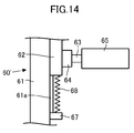
- the upper body support portion moves in the vertical direction. It is also possible to adopt an embodiment in which the upper body support portion drive mechanism is attached so as to be in a free state (19th invention). According to this, by attaching the upper body support portion to the upper body of the operator, the vertical movement of the upper body of the operator is followed without the need for an actuator for driving the upper body support portion in the vertical direction.
- the upper body support can be moved up and down.
- the upper body support portion is in the vertical direction. It is also possible to adopt an embodiment in which the upper body support portion drive mechanism is attached so as to be able to move elastically (20th invention).
- the upper body support portion is in a state of being rotatable in the roll direction of the operator, in the pitch direction of the operator, or in the roll direction and the pitch direction.
- the roll direction means the direction around the axis in the front-rear direction of the operator
- the pitch direction means the direction around the axis in the left-right direction of the operator.
- the operator smoothly tilts the upper body in the roll direction, the pitch direction, or the roll direction and the pitch direction during walking without feeling any resistance. It becomes possible. As a result, the operator can move smoothly by walking.
- control system of the present invention can be configured as a system having the control devices of the first to twenty-first inventions and the moving body.
- the control system is a control system including the control device according to any one of the fifth to eighth inventions and the thirteenth to sixteenth inventions and the moving body
- the moving body is the control system.
- a moving mechanism for a moving body configured to be able to move on the floor surface of a moving environment, and an upper body mounted on the moving mechanism for the moving body via a force detector for detecting the first reaction force. It is preferable to have a portion (22nd invention). According to this, the reaction force received from the outside world by the upper body portion of the moving body (excluding the floor reaction force received from the floor surface via the moving mechanism for the moving body) can be appropriately detected by the force detector. It will be possible.
- the upper body portion includes a cover that covers the periphery of the moving mechanism for the moving body (23rd invention). According to this, the reaction force received by the cover from an obstacle or the like in contact with the moving mechanism for the moving body can also be detected by the force detector as the first reaction force.
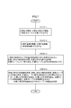
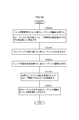
- FIG. 5 is a flowchart showing processing of the main steering control unit shown in FIG.
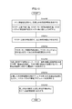
- the flowchart which shows the subroutine processing of STEP3 of FIG.
- the flowchart which shows the subroutine processing of STEP4 of FIG.
- the flowchart which shows the processing of the slave movement control part shown in FIG.
- FIG. 11A is an explanatory diagram regarding processing of the slave movement control unit
- FIG. 11B is an explanatory diagram regarding processing of the master movement control unit.
- the flowchart which shows the processing of the slave manipulator control part shown in FIG. The flowchart which shows the processing of the master manipulator control part shown in FIG.
- FIG. 5 is a perspective view showing still another example of the upper body support drive mechanism.
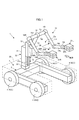
- the control device 51 for controlling the moving body 1 illustrated in FIG. 1 will be described.
- the mobile body 1 to be operated is referred to as a slave device 1
- the control device 51 for controlling the slave device 1 is referred to as a master device 51.
- the slave device 1 includes a moving mechanism 2 capable of moving on the floor surface of the operating environment thereof, and a manipulator 10 mounted on the moving mechanism 2.
- the "floor surface” is not limited to the floor surface in the usual sense, but may include the ground, the road surface, and the like.
- the "front-back direction”, “left-right direction”, and “vertical direction” of the slave device 1 are the X-axis direction, the Y-axis direction, and the Z-axis of the three-axis Cartesian coordinate system Cs shown in FIG. 1, respectively.
- the front-rear direction (X-axis direction) and the left-right direction (Y-axis direction) correspond to the "lateral direction" in the present invention.
- the moving mechanism 2 corresponds to the moving mechanism for a moving body in the present invention.
- the moving mechanism 2 includes a base 3 and a plurality of moving grounding portions 4 attached to the base 3, and a plurality of moving grounding portions 4 are provided with a space between the base 3 and the floor surface. Is grounded on the floor.
- the base 3 has a bifurcated shape (substantially U-shaped) when viewed from above, but the base 3 has an arbitrary shape. It's fine.
- the moving mechanism 2 includes, for example, four moving grounding portions 4 (1), 4 (2), 4 (3), 4 (4) as a plurality of moving grounding portions 4. Then, two moving grounding portions 4 (1) and 4 (4) are attached to both left and right sides of the front portion of the base 3, and two moving grounding portions 4 (2) are attached to both left and right sides of the rear portion of the base 3. , 4 (3)) are attached.
- Each moving ground contact portion 4 is simply described in a wheel shape in FIG. 1, but in detail, it is configured so that it can move in all directions on the floor surface while being in contact with the floor surface.
- each mobile grounding portion 4 has the same structure as the main wheel described in, for example, Japanese Patent Application Laid-Open No. 2013-237329 or US Pat. No. 9027693. Therefore, detailed description of the configuration of each mobile grounding unit 4 and its drive mechanism in the present specification will be omitted.
- the moving mechanism 2 provided with the moving grounding portion 4
- two electric motors 5a and 5b shown in FIG. 2 as power sources for the movement of each moving grounding portion 4 are shown.
- a mobile drive mechanism 5 (shown in FIG. 2) is mounted. Then, as described in Japanese Patent Application Laid-Open No. 2013-237329 or US Pat. No. 9027693, the moving drive mechanism 5 corresponding to each moving grounding portion 4 is provided from the two electric motors 5a and 5b. By transmitting power to 4, the moving ground contact portion 4 can be moved in all directions.
- each moving ground portion 4 has a speed whose speed component in the front-rear direction (X-axis direction) of the slave device 1 is proportional to the sum of the rotation speeds of the two electric motors 5a and 5b in the moving speed vector.
- the speed component in the left-right direction (Y-axis direction) is driven so as to be proportional to the difference in the rotational speeds of the two electric motors 5a and 5b.
- each movable grounding portion 4 that can move in all directions is not limited to that described in Japanese Patent Application Laid-Open No. 2013-237329 or US Pat. No. 9027693, such as Omni Wheel (registered trademark), etc. It may have the structure of. Further, the number of the moving grounding portions 4 provided in the moving mechanism 2 is not limited to 4, and may be, for example, 3 or 5 or more. Further, the power source of each mobile grounding portion 4 is not limited to the electric motors 5a and 5b, and for example, a hydraulic motor can be used.
- a manipulator 10 is attached to the base 3 via an elevating mechanism 30.
- the elevating mechanism 30 can move (elevate) in the vertical direction with respect to the support column 31 erected upward from the central portion (central portion in the left-right direction) of the rear portion of the base 3 and the support column 31.
- the slide member 32 assembled as described above is provided.
- the force detector 33 receives a reaction force (excluding the floor reaction force received from the floor surface via the moving mechanism 2) received from the outside world by the upper body portion (a portion supported on the base 3) of the slave device 1. It is for detecting, and will be referred to as an upper physical strength detector 33 hereafter.
- the upper physical strength detector 33 corresponds to the force detector of the moving body in the present invention, and the reaction force detected by the upper physical strength detector 33 corresponds to the first reaction force in the present invention.
- the upper physical strength detector 33 is composed of, for example, a 6-axis force sensor, and can detect the translational force and the moment of force as three-dimensional vectors, respectively. In the following description, the "moment of force" is simply referred to as a moment.
- the upper body portion of the slave device 1 (the portion supported on the base 3) may be hereinafter referred to as the slave upper body.
- a guide rail 31a extending in the vertical direction is attached to the front surface portion of the support column 31. Then, the slide member 32 is engaged with the guide rail 31a so as to be able to move up and down along the guide rail 31a.
- the guide mechanism may be different from the above.
- the elevating mechanism 30 includes a slide drive actuator 36 (shown in FIG. 2) which is an actuator for elevating and lowering the slide member 32 with respect to the support column 31.
- the slide drive actuator 36 is composed of, for example, an electric motor.
- the slide drive actuator 36 applies a driving force for raising and lowering the slide member 32 with respect to the support column 31 to the slide member 32 via, for example, a rotation / linear motion conversion mechanism (not shown) such as a ball screw mechanism. It is attached to the support column 31 or the slide member 32 so as to raise and lower the slide member 32.
- the slide drive actuator 36 is not limited to the electric motor, and for example, a hydraulic motor or a hydraulic cylinder can be used.
- the manipulator 10 corresponds to the working manipulator in the present invention, and is attached to the slide member 32 in the present embodiment.
- the manipulator 10 includes a pair of left and right hands 21L and 21R, and these two hands 21L and 21R are connected to the slide member 32 via a plurality of joints.
- the manipulator 10 is attached to, for example, a first link 13 extending from a slide member 32 via a first joint mechanism 12 and a tip portion of the first link 13 via a second joint mechanism 14.
- each force detector 22 (hereinafter referred to as a hand force detector 22) is composed of, for example, a 6-axis force sensor, similarly to the upper physical strength detector 33.
- Each hand 21 may include a mechanism for gripping an object, a mechanism for detachably adsorbing an object, an electric tool, or the like.
- Each of the joint mechanisms 12, 14, 16, 18, and 20 is a joint mechanism having a known structure, and is composed of one or a plurality of joints so as to have, for example, one or more degrees of freedom of rotation.
- joint means a joint which has uniaxial rotational degrees of freedom unless otherwise specified.
- each of the left and right hands 21 has 7 or more degrees of freedom of movement.
- the third joint mechanism 16 corresponding to the shoulder joints of the left and right arms of the manipulator 10 the fourth joint mechanism 18 corresponding to the elbow joint, and the fifth joint mechanism 20 corresponding to the wrist joint have three axes, respectively.
- the degree of freedom of rotation of 1 axis can be configured to have a degree of freedom of rotation of 3 axes.
- each joint actuator 24 is composed of, for example, an electric motor.
- each hand 21 may be connected to the slide member 32 via, for example, a three-axis slide mechanism.
- each joint actuator 24 is not limited to an electric motor, and can be configured by, for example, a hydraulic motor or a hydraulic actuator such as a hydraulic cylinder.
- the slave device 1 of the present embodiment is further equipped with a cover 26 for preventing an external object from hitting the moving mechanism 2.
- the cover 26 is formed below the manipulator 10 so as to cover the entire circumference and the upper surface of the moving mechanism 2, as shown by a two-dot chain line in FIG. 1, for example, and a support column is provided via an appropriate mounting member (not shown). It is fixed at 31.
- the slave device 1 of the present embodiment it is prevented that an object or the like existing in the outside world directly hits the moving mechanism 2 while the slave device 1 is moving.
- the cover 26 receives a reaction force (external force such as a contact reaction force) from the outside world, the reaction force is transmitted from the cover 26 to the upper physical strength detector 33 via the support column 31.
- the reaction force (external force such as contact reaction force) received by the manipulator 10 from the outside world is transmitted from the manipulator 10 to the upper physical strength detector 33 via the slide member 32 and the support column 31. It is supposed to be transmitted.
- the upper physical strength detector 33 removes the floor reaction force received from the floor surface by the slave upper body via the moving mechanism 2, and the slave device 1 can detect the reaction force received by the slave upper body from the outside world. It is installed in.
- the slave upper body corresponding to the upper body portion of the moving body in the present invention is composed of the elevating mechanism 30, the manipulator 10, and the cover 26.
- the slave device 1 is further equipped with a communication device 40 for wirelessly communicating with the master device 51 and a control device 41 having a function of controlling the operation of the slave device 1.
- a communication device 40 for wirelessly communicating with the master device 51 and a control device 41 having a function of controlling the operation of the slave device 1.
- the motor rotation detection as a detector for detecting the driving state of each moving grounding portion 4 by each moving driving mechanism 5.
- a device 27, a joint displacement detector 28 as a detector for detecting the operating state of the manipulator 10, and a slide displacement detector 29 for detecting the displacement (vertical position) of the slide member 32 are mounted. There is.
- the motor rotation detector 27 determines, for example, the rotation angle of the rotation shafts (or rotating members that rotate in conjunction with the rotation shafts) of the electric motors 5a and 5b for each movement drive mechanism 5 in the driving state of the movement drive mechanism 5. It is a detector that can be detected as a state quantity indicating. Further, the joint displacement detector 28 detects, for example, the displacement (rotation angle) of each joint constituting each joint mechanism 12, 14, 16, 18, 20 of the manipulator 10 as a state quantity indicating the operating state of the manipulator 10. It is a possible detector. Each of the motor rotation detector 27 and the joint displacement detector 28 may be composed of, for example, a rotary encoder, a resolver, a potentiometer, or the like.
- the slide displacement detector 29 is composed of, for example, a known contact type or non-contact type displacement sensor. Further, for example, when the power transmission mechanism from the slide drive actuator 36 to the slide member 32 is configured so that the displacement of the slide member 32 is proportional to the rotation angle of the rotation axis of the slide drive actuator 36, the said.
- a detector capable of detecting the rotation angle of the rotation axis of the slide drive actuator 36 (or a rotating member that rotates in conjunction with the rotation axis) can also be used as a slide displacement detector. In this case, the slide displacement detector 29 may be the same detector as the motor rotation detector 27.
- the slave device 1 is provided with a plurality of movement drive mechanism 5, motor rotation detector 27, joint actuator 24, joint displacement detector 28, and hand force detector 22, but in FIG. 2, each of them is provided. Only one is typically listed.
- the control device 41 is composed of one or more electronic circuit units including, for example, a microcomputer, a memory, an interface circuit, and the like. Although detailed description will be described later, command data indicating the operation target (target movement) of the slave upper body and each hand 21 is input from the master device 51 to the control device 41 via the communication device 40, and the slave The detection data of each detector mounted on the device 1 (upper body force detector 33, each motor rotation detector 27, slide displacement detector 29, each joint displacement detector 28, and each hand force detector 22) is input. Will be done.
- control device 41 moves the upper body of the slave device 1 as a function realized by both or one of the mounted hardware configuration and the program (software configuration), and the electric motor 5a of each movement drive mechanism 5 A function as a slave movement control unit 42 that controls via the 5b and the slide drive actuator 36, and a function as a slave manipulator control unit 43 that controls the operation of each hand 21 of the manipulator 10 via each joint actuator 24.
- the control device 41 can output (transmit) data indicating the actual operating state of the slave device 1 (hereinafter referred to as an actual slave state) to the master device 51 via the communication device 40.
- slave may be added to the beginning of the name of the component of the slave device 1 as appropriate.
- the base 3 of the slave device 1 may be referred to as the slave base 3.
- the configuration of the master device 51 will be described with reference to FIGS. 3 to 5.
- the "front-back direction”, “horizontal direction”, and “vertical direction” of the master device 51 are the X-axis direction and the Y-axis direction of the 3-axis Cartesian coordinate system Cm shown in FIG. 3 or 4, respectively. , Z-axis direction.
- the front-rear direction (X-axis direction) and the left-right direction (Y-axis direction) correspond to the "lateral direction” in the present invention.
- the reference code of the component on the left side and the reference code of the component on the right side are appropriately designated as necessary. "L” and "R” are added.
- the master device 51 corresponds to the control device in the present invention.
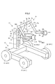
- the master device 51 includes a moving mechanism 52 capable of moving on the floor surface of the operating environment of the operator P (shown in FIG. 4) operating the slave device 1, and an upper body support mounted on the upper body of the operator P.
- a unit 65 and a manipulator 70 for the operator P to operate the slave manipulator 10 are provided.
- the moving mechanism 52 has the same configuration as the slave moving mechanism 2, and similarly to the slave moving mechanism 2, the base 53 and a plurality of (four) moving grounding portions attached to the base 53. It includes 54 (54 (1), 54 (2), 54 (3), 54 (4)). Further, although detailed illustration is omitted, the moving mechanism 52 includes a moving drive mechanism 55 having electric motors 55a and 55b and a motor rotation detector as components corresponding to the moving grounding portions 54, as shown in FIG. 87 is provided in the same manner as the slave moving mechanism 2. The electric motors 55a and 55b correspond to the first actuator in the present invention.
- the upper body support portion 65 and the manipulator 70 are attached to the base 53 via the elevating mechanism 60.
- the elevating mechanism 60 together with the moving mechanism 52, constitutes the upper body support portion driving mechanism in the present invention.
- the elevating mechanism 60 can move (elevate) in the vertical direction with respect to the column 61 erected upward from the central portion (central portion in the left-right direction) of the rear portion of the base 53 and the column 61.
- the slide member 62 assembled as described above is provided.
- the support column 61 is fixed to the base 53.
- a guide rail 61a extending in the vertical direction is attached to the front surface portion of the support column 61. Then, the slide member 62 is engaged with the guide rail 61a so as to be able to move up and down along the guide rail 61a.
- the guide mechanism may be different from the above.
- the master device 51 is equipped with a slide drive actuator 66 (shown in FIG. 5), which is an actuator for raising and lowering the slide member 62 with respect to the support column 61.
- the slide drive actuator 66 corresponds to the second actuator in the present invention, and is composed of, for example, an electric motor.
- the slide drive actuator 66 raises and lowers the slide member 62 via a power transmission mechanism similar to the power transmission mechanism from the slide drive actuator 36 of the slave device 1 to the slide member 32, for example.
- the slide drive actuator 66 is not limited to an electric motor, and for example, a hydraulic motor or a hydraulic cylinder can be used.
- the upper body support portion 65 is configured so that it can be aligned with a predetermined portion of the upper body of the operator P, for example, the outer circumference of the waist portion from the back side.
- the upper body support portion 65 is composed of a plate-shaped member formed in a substantially semicircular arc shape (or U shape). The upper body support portion 65 is attached to the slide member 62 via a support shaft 63 and a force detector 64.
- the support shaft 63 is attached to the slide member 62 via a force detector 64 with its axis oriented in the front-rear direction (X-axis direction).
- the force detector 64 (hereinafter referred to as the upper body strength detector 64) is a detector for detecting the reaction force (contact reaction force) received by the upper body support portion 65 from the upper body of the operator P, and is on the slave. Similar to the physical strength detector 33, it is composed of, for example, a 6-axis force sensor.
- the upper body support portion 65 has a central portion between both ends attached to the support shaft 63.
- the upper body support portion 65 allows the slide member 62 and the upper body force detector 64 to freely rotate around the axis of the support shaft 63 (in other words, in the roll direction). Is supported by.
- the upper body support portion 65 When the operator P operates the slave device 1, the upper body support portion 65 is arranged so as to be along the outer periphery of the waist portion of the upper body of the operator P from the back side thereof, as shown in FIG. A flexible belt 65x (shown by a two-dot chain line in FIG. 4) is connected to both ends of the upper body support portion 65 so as to be arranged along the outer circumference of the waist portion of the operator P on the front surface side. Will be done.
- the upper body support portion 65 and the belt 65x surround the waist portion of the upper body of the driver P, and the upper body support portion 65 is attached to the waist portion of the driver P via the belt 65x.
- the upper body support portion 65 is mounted so as not to be displaced relative to the waist portion of the operator P.
- the upper body support portion 65 can adjust the height (position in the vertical direction) of the upper body support portion 65 by appropriately moving the slide member 62 up and down.
- an elastic member such as a pad (not shown) is attached to the inner peripheral surface of the upper body support portion 65, and the elastic member is brought into contact with the periphery of the waist portion of the operator P.
- the upper body support portion 65 In the state where the upper body support portion 65 is attached to the waist of the operator P in this way, the upper body support portion 65 and the moving mechanism 52 can move together with the operator P as the operator P moves (walks). become. In this case, the pilot P can tilt his upper body back and forth and left and right. Further, the reaction force received by the upper body support portion 65 from the lumbar region of the operator P is detected by the upper body force detector 64.
- the manipulator 70 corresponds to the manipulator for maneuvering in the present invention, and is attached to the slide member 62 in the present embodiment.
- the manipulator 70 includes two pairs of left and right hands 81L and 81R that can be attached to the left and right wrists (or a portion in the vicinity thereof) of the operator P via a belt (not shown), and the plurality of these hands 81L and 81R are present. It is connected to the slide member 62 via a joint.
- the connection structure between the hands 81L and 81R and the slide member 62 is the same as, for example, the slave manipulator 10. That is, the manipulator 70 has a first link 73 extending from the slide member 62 via the first joint mechanism 72 on the upper side of the upper physical strength detector 64, and a second joint mechanism 74 at the tip of the first link 73. A pair of left and right second links 75L and 75R attached via the second links 75L and 75R, and third links 77L and 77R attached to the tips of the second links 75L and 75R via the third joint mechanisms 76L and 76R, respectively.
- the tips of the third links 77L and 77R are provided with the fourth links 79L and 79R attached via the fourth joint mechanisms 78L and 78R, respectively, and the fifth joint mechanism is provided at the tips of the fourth links 79L and 79R, respectively.
- the hands 81L and 81R are attached via the 80L and 80R and the force detectors 82L and 82R, respectively.
- each force detector 82 is for detecting the reaction force (contact reaction force) received by each hand 81 from the tip end side portion (hand or the like) of each arm of the operator P, and detects the physical strength of the slave.
- the vessel 33 and the like it is composed of, for example, a 6-axis force sensor.
- each force detector 82 will be referred to as a hand force detector 82.
- the resultant force of the reaction forces detected by the left and right hand force detectors 82L and 82R respectively corresponds to the second reaction force in the present invention.
- the manipulator 70 having the above configuration has, similarly to the slave manipulator 10, each joint (one-axis rotation degree of freedom) constituting each joint mechanism 72, 74, 76, 78, 80.
- a plurality of joint actuators 84 (shown in FIG. 5) for driving each of the joints having the joints) are mounted.
- Each joint actuator 84 is composed of, for example, an electric motor.
- the manipulator 70 is not limited to the rotary type joint, but may include a linear motion type joint. Further, the connection structure between each hand 81 and the slide member 62 may be different from that of the slave manipulator 10. Each hand 21 may be connected to the slide member 62 via, for example, a three-axis slide mechanism. Further, each joint actuator 84 is not limited to an electric motor, and can be configured by, for example, a hydraulic motor or a hydraulic actuator such as a hydraulic cylinder.
- the master device 51 is further equipped with a communication device 90 for wirelessly communicating with the slave device 1 and a control device 91 having a function of controlling the operation of the master device 51.
- a communication device 90 for wirelessly communicating with the slave device 1 and a control device 91 having a function of controlling the operation of the master device 51.
- the motor rotation detection as a detector for detecting the driving state of each moving ground contact portion 54 by each moving driving mechanism 55.
- a device 87, a joint displacement detector 85 as a detector for detecting the operating state of the manipulator 70, and a slide displacement detector 89 for detecting the displacement (vertical position) of the slide member 62 are mounted. There is.
- the motor rotation detector 87 determines the rotation angle of each rotation axis (or a rotation member that rotates in conjunction with the rotation axis) of the electric motors 55a and 55b for each movement drive mechanism 55. It is a detectable detector.
- the joint displacement detector 85 is a detector capable of detecting the displacement (rotation angle) of each joint constituting each joint mechanism 72, 74, 76, 78, 80 of the manipulator 70.
- the same configuration of the slave motor rotation detector 27 and the slave joint displacement detector 28 can be used.
- the slide displacement detector 89 may also have the same configuration as the slave slide displacement detector 29.
- the master device 51 is provided with a plurality of movement drive mechanism 55, motor rotation detector 87, joint actuator 84, joint displacement detector 85, and hand force detector 82, but in FIG. 5, each of them is provided. Only one is typically listed.
- the control device 91 is composed of one or more electronic circuit units including, for example, a microcomputer, a memory, an interface circuit, and the like. Although detailed description will be described later, data indicating the actual slave state is input from the slave device 1 to the control device 91 via the communication device 90, and the upper physical strength detector 64 of the master device 51 and each hand force. The detection data of the detector 82, each motor rotation detector 87, and each joint displacement detector 85 are input.
- the control device 91 generates the overall operation target (target motion) of the slave device 1 and the master device 51 as a function realized by both or one of the mounted hardware configuration and the program (software configuration).
- the manipulator 70 has a function as a master manipulator control unit 93 that controls the operation of the manipulator 70 via each joint actuator 84.
- the control device 91 can output (transmit) command data indicating the operation target (target motion) of the slave device 1 to the slave device 1 via the communication device 90.
- master may be added to the beginning of the name of the component of the master device 51 as appropriate.
- the base 53 of the master device 51 may be referred to as the master base 53.
- the main steering control unit 94 of the master device 51 has a function as a movement command determining unit in the present invention, and also has a function as a first control unit in the present invention together with the master movement control unit 92.
- the name of an arbitrary state quantity with "target” added to the beginning, or the reference code of the state quantity with the subscript “_aim” added means the target value of the state quantity.
- the reference code with " ⁇ " at the beginning is a reference code representing a vector (vertical vector).
- a "slave” may be added at the beginning of the name of the state quantity or between the name of the state quantity and the "actual” or “target”. .. This also applies to the state quantity associated with the master device 51.
- the "movement" of an arbitrary object means a state quantity of any one of the position, velocity (translational velocity), posture angle, and angular velocity of the object, or a set of two or more state quantities.
- the posture angle is an angle (azimuth) representing the direction of the object as seen in a certain coordinate system.
- the posture angles are represented by, for example, Euler angles.
- the posture angle may be simply referred to as a posture.
- the main control unit 94 sequentially executes the processes shown in the flowchart of FIG. 6 at a predetermined control process cycle.
- the main control unit 94 acquires (receives) data indicating the actual slave state as the actual operating state of the slave device 1 from the slave control device 41 via the communication devices 40 and 90.
- the actual slave upper body reaction force which is the actual reaction force that the slave upper body (upper body of the slave device 1) receives from the outside world other than the floor reaction force
- the slave upper body The actual slave upper body movement, which is the actual movement of, the actual slave hand movement, which is the actual movement of each slave hand 21, and the actual slave hand reaction force, which is the reaction force that each slave hand 21 actually receives from the outside world. included.
- the actual slave upper body reaction force is the resultant force of the actual reaction force received from the outside world by the slave upper body via the support column 31, the cover 26, or the manipulator 10. Further, each of the actual slave upper body reaction force and the left and right actual slave hand reaction force is composed of a pair of translational force and moment. Then, each of the translational force and the moment of the actual slave upper body reaction force acquired by the main control unit 94 in STEP 1 is a global coordinate system arbitrarily designed and set with respect to the operating environment of the slave device 1 (the operation). It is represented as a three-dimensional vector as seen in a three-dimensional coordinate system fixed to the floor of the environment; hereinafter referred to as a slave-side global coordinate system).
- the respective moments of the actual slave upper body reaction force and the left and right actual slave hand reaction forces are, more specifically, at the predetermined reference points (hereinafter referred to as slave reference points Qs) set for the slave device 1. It is a moment around.
- the slave reference point Qs can be appropriately set in consideration of the structure of the slave device 1 and the like.
- the master moving mechanism 52 and the slave moving mechanism 2 have substantially the same or substantially similar shapes.
- the positional relationship between the slave reference point Qs and the slave moving mechanism 2 and the positional relationship between the reference point Qm and the master moving mechanism 52, which will be described later in the master device 51, are substantially the same or similar to each other.
- the slave reference point Qs can be set so as to be.
- the slave reference points Qs shown in FIG. 11A exemplify the reference points set from such a viewpoint. Note that in FIG. 11A, the manipulator 10 is not shown.
- the moments of the left and right real slave hand reaction forces are set to the predetermined reference points set for the respective slave hands 21L and 21R (hereinafter, the slave hand reference). It is converted into moments around points Qhs_L and Qhs_R), and the moments of the left and right real master hand reaction forces are converted to predetermined reference points (hereinafter referred to as master hands) set for the respective master hands 81L and 81R. It is preferable to convert it into a moment around the reference point (referred to as Qhm_L and Qhm_R). This transformation makes the bilateral control characteristics more appropriate.
- ⁇ F_sb_act and ⁇ M_sb_act are used as reference codes for the translational force and the moment of the actual slave upper body reaction force, respectively.
- ⁇ F_sh_act_L and ⁇ M_sh_act_L are used as reference codes for the translational force and moment of the actual slave hand reaction force on the left side
- ⁇ F_sh_act_R is used as the reference code for the translational force and moment of the real slave hand reaction force on the right side.
- ⁇ Use M_sh_act_R Use M_sh_act_R.
- ⁇ F_sh_act ⁇ F_sh_act_L + ⁇ F_sh_act_R
- ⁇ M_sh_act ⁇ M_sh_act_L + ⁇ M_sh_act_R.
- the actual slave upper body motion includes the position of the slave upper body as seen in the above slave-side global coordinate system ⁇ P_sb_act, translation velocity ⁇ V_sb_act, posture angle ⁇ ⁇ _sb_act, and angular velocity ⁇ ⁇ _sb_act.
- the real slave hand motion includes the position ⁇ P_sh_act, translational velocity ⁇ V_sh_act, attitude angle ⁇ ⁇ _sh_act, and angular velocity ⁇ ⁇ _sh_act of each slave hand 21 as seen in the slave-side global coordinate system.
- the position of the slave upper body ⁇ P_sb_act is the position of the representative point set (defined) in advance with respect to the slave upper body, for example, the position of the slave reference point Qs.
- the vertical axis component (yaw direction component) of the slave upper body posture angle ⁇ ⁇ _sb_act is the vertical axis component (yaw direction component) of the slave base 3 posture angle. Ingredient) is considered to match.
- all or part of the actual slave state output from the slave control device 41 to the main control control unit 94 is the local coordinate system set for the slave device 1 (for example, the slave upper body coordinates described later). It may be the state quantity seen in the system Cs).
- the main control unit 94 sees the actual slave state (actual slave state as seen in the local coordinate system) given by the slave control device 41 in the slave-side global coordinate system as the actual slave state. Convert to and get.
- the main maneuvering control unit 94 may omit to acquire the posture angle and the angular velocity around the lateral axis among the posture angle ⁇ ⁇ _sb_act and the angular velocity ⁇ ⁇ _sb_act of the actual slave upper body movement.
- the moment of the reaction force of the actual slave upper body ⁇ M_sb_act it is possible to omit acquiring the moment around the axis in the lateral direction.
- the main manipulator control unit 94 acquires data indicating the actual master state, which is the actual operating state of the master device 51, from the master movement control unit 92 and the master manipulator control unit 93.
- the actual upper body support portion reaction force which is the actual reaction force received by the upper body support portion 65 from the operator P, and the actual movement of the upper body support portion 65.
- Each of the above-mentioned actual body support reaction force and the left and right actual master hand reaction force is composed of a pair of translational force and moment.
- Each of these translational forces and moments is a global coordinate system arbitrarily designed and set with respect to the operating environment of the master device 51 (a three-dimensional coordinate system fixed to the floor of the operating environment. , Represented as a three-dimensional vector as seen in the master-side global coordinate system).
- the respective moments of the reaction force of the actual body support portion and the reaction force of the left and right actual master hands are, more specifically, a predetermined reference point set for the master device 51 (hereinafter referred to as a master reference point Qm).
- a master reference point Qm is an intermediate point between the left and right side portions of the upper body support portion 65 on the axial center of the support shaft 63 (the operator wearing the upper body support portion 65). It can be set at a point near the center of the waist of P). Note that FIG. 11B omits the illustration of the master manipulator 70.
- ⁇ F_mb_act and ⁇ M_mb_act will be used as reference codes to represent the translational force and moment of the reaction force of the actual body support, respectively.
- ⁇ F_mh_act_L and ⁇ M_mh_act_L are used as reference codes for the translational force and moment of the actual master hand reaction force on the left side
- ⁇ F_mh_act_R is used as the reference code for the translational force and moment of the actual master hand reaction force on the right side.
- ⁇ Use M_mh_act_R Use M_mh_act_R.
- the resultant force of the left and right real master hand reaction forces is called the actual master hand resultant force, and "L” and “R” are not added as reference codes to represent the translational force and moment of the actual master hand resultant force.
- F_mh_act and ⁇ M_mh_act Use F_mh_act and ⁇ M_mh_act.
- ⁇ F_mh_act ⁇ F_mh_act_L + ⁇ F_mh_act_R
- ⁇ M_mh_act ⁇ M_mh_act_L + ⁇ M_mh_act_R.
- the actual body support movement includes the position ⁇ P_mb_act, translation speed ⁇ V_mb_act, posture angle ⁇ ⁇ _mb_act, and angular velocity ⁇ ⁇ _mb_act of the upper body support 65 as seen in the above master-side global coordinate system.
- the actual master hand motion includes the position ⁇ P_mh_act, translational velocity ⁇ V_mh_act, attitude angle ⁇ ⁇ _mh_act, and angular velocity ⁇ ⁇ _mh_act of each master-hand 81 as seen in the master-side global coordinate system.
- the position ⁇ P_mb_act of the upper body support portion 65 is a position of a representative point preset with respect to the upper body support portion 65, for example, a position of the master reference point Qm. Further, in the present embodiment, the posture angle ⁇ ⁇ _mb_act of the upper body support portion 65 is considered to match the posture angle of the master base 53.
- all or part of the actual master state output from the master movement control unit 92 and the master manipulator control unit 93 to the main control control unit 94 is a local coordinate system set for the master device 50 (for example,). , It may be the state quantity seen in the master upper body coordinate system Cm) described later.
- the main manipulator control unit 94 sets the real slave state (real slave state as seen in the local coordinate system) given by the master movement control unit 92 or the master manipulator control unit 93 in STEP 2 to the master side global coordinates. Convert to the actual master state seen in the system and acquire it.
- the main maneuvering control unit 94 may omit to acquire the posture angle and the angular velocity around the axis in the lateral direction among the posture angle ⁇ ⁇ _mb_act and the angular velocity ⁇ ⁇ _mb_act of the actual body support movement.
- Actual body support part reaction force moment ⁇ Of M_mb_act it is possible to omit to acquire the moment around the axis in the lateral direction.
- the main maneuvering control unit 94 executes the processing of the upper body side bilateral control which is the bilateral control regarding the operation of the upper body of the master device 51 and the upper body of the slave device 1.
- This upper body side bilateral control process is executed as shown in the flowchart of FIG.
- the main control unit 94 calculates the upper body reaction force deviation.
- the upper body reaction force deviation is the upper body reaction force translational force deviation ⁇ Efb, which is the upper body reaction force deviation related to the translational force, and the upper body reaction force moment deviation ⁇ Efb, which is the upper body reaction force deviation related to the moment. It is composed of Emb.
- the upper body reaction force translational force deviation ⁇ Efb is, for example, the translational force of the actual master hand resultant force ⁇ F_mh_act, the translational force of the actual slave upper body reaction force ⁇ F_sb_act, and the translational force of the actual slave hand resultant force ⁇ F_sh_act. It is defined as an index value indicating the degree of deviation (deviation degree) of the mutual relationship between one or more translational forces and the translational force of the reaction force of the actual body support ⁇ F_mb_act from a predetermined target relationship.
- the upper body reaction force moment deviation ⁇ Emb is one of, for example, the actual master hand resultant force moment ⁇ M_mh_act, the actual slave upper body reaction force moment ⁇ M_sb_act, and the actual slave hand resultant force moment ⁇ M_sh_act. It is defined as an index value indicating the degree of deviation (deviation degree) from the predetermined target relationship between the above moment and the moment of the reaction force of the actual body support ⁇ M_mb_act.
- the left and right real master hand reaction forces and the real slave hand reaction forces are proportional to each other at a predetermined ratio for each of the translational force and the moment by the hand-side bilateral control described later.
- the operations of the left and right master hands 81 and slave hands 21 are controlled.
- one of the translational force of the actual master hand resultant force ⁇ F_mh_act and the translational force of the actual slave hand resultant force ⁇ F_sh_act becomes the dependent variable of the other, and the moment of the actual master hand resultant force ⁇ M_mh_act and the moment of the actual slave hand resultant force ⁇ M_sh_act. Is the other dependent variable.
- the upper body reaction force translational force deviation ⁇ Efb is set to, for example, the translational force ⁇ F_mh_act of the actual master hand resultant force and the translational force ⁇ F_sh_act of the actual slave hand resultant force, for example, ⁇ F_mh_act and the actual slave. It is defined by the following equation (1a) as an index value expressed by a function of the translational force of the body reaction force ⁇ F_sb_act and the translational force of the actual body support part reaction force ⁇ F_mb_act.
- the upper body reaction force moment deviation ⁇ Emb for example, the moment of the actual master hand resultant force ⁇ M_mh_act and the moment of the actual slave hand resultant force ⁇ M_sh_act, for example ⁇ M_mh_act, and the moment of the actual slave upper body reaction force ⁇ M_sb_act
- ⁇ M_mh_act the moment of the actual master hand resultant force ⁇ M_mh_act
- ⁇ M_sb_act for example, the moment of the actual slave upper body reaction force ⁇ M_sb_act
- Ratio_fsb, Ratio_fmh, Ratio_msb, and Ratio_mmh in the equations (1a) and (1b) are coefficients representing the respective return rates of ⁇ F_sb_act, ⁇ F_mh_act, ⁇ M_sb_act, and ⁇ M_mh_act with respect to the pilot P, respectively. It is set to a predetermined value set in advance.
- the coefficient may be either a scalar or a diagonal matrix.
- the coefficients Ratio_fsb and Ratio_msb of the second term on the right side of each of the equations (1a) and (1b) are set to the same values, and the coefficients Ratio_fmh and Ratio_mmh of the third term are set to the same values. Will be done. However, it is also possible to set Ratio_fsb and Ratio_msb to different values, or to set Ratio_fmh and Ratio_mmh to different values.
- Ratio_fsb and Ratio_fmh in the formula (1a) it is also possible to set one or both of Ratio_fsb and Ratio_fmh in the formula (1a) to zero, and set one or both of Ratio_msb and Ratio_mmh in the formula (1a) to zero, which will be described later. .. Therefore, in the present embodiment, it is assumed that Ratio_fsb ⁇ 0, Ratio_fmh ⁇ 0, Ratio_msb ⁇ 0, and Ratio_mmh ⁇ 0.
- the main control unit 94 is the resultant force of the actual slave upper body reaction force ( ⁇ F_sb_act, ⁇ M_sb_act) acquired in STEP1 and the left and right actual master hand reaction forces acquired in STEP2. From the actual master hand resultant force ( ⁇ F_mh_act, ⁇ M_mh_act) and the actual upper body support reaction force ( ⁇ F_mb_act, ⁇ M_mb_act) acquired in STEP 2, the upper body reaction force deviation according to the above equations (1a) and (1b). Calculate ( ⁇ Efb, ⁇ Emb).
- the upper body reaction force deviation ( ⁇ Efb, ⁇ Emb) is calculated using the actual slave hand resultant force ( ⁇ F_sh_act, ⁇ M_sh_act) proportional to this instead of the actual master hand resultant force ( ⁇ F_mh_act, ⁇ M_mh_act). It is also possible to do.
- the main maneuvering control unit 94 calculates the upper body position / posture deviation.
- the upper body position and posture deviations are the upper body position deviation ⁇ Epb regarding the positions of the upper body support 65 and the slave upper body, and the upper body posture deviation ⁇ Epb regarding the respective posture angles of the upper body support 65 and the slave upper body. It is composed of Ethb.
- the upper body position deviation ⁇ Epb is an index value indicating the degree of deviation (dissociation degree) of the mutual relationship between the position of the upper body support portion 65 ⁇ P_mb_act and the position of the slave upper body ⁇ P_sb_act from a predetermined target relationship. Is defined as.
- the upper body posture deviation ⁇ Ethb determines the degree of deviation (degree of deviation) from the predetermined target relationship between the posture angle ⁇ ⁇ _mb_act of the upper body support portion 65 and the posture angle ⁇ ⁇ _sb_act of the slave upper body. It is defined as an index value to represent.
- the position of the slave upper body ⁇ P_sb_act and the posture angle ⁇ ⁇ _sb_act are, for example, the position of the upper body support portion 65 ⁇ P_mb_act multiplied by (1 / Ratio_psb) and above.
- the posture angle of the body support portion 65 is controlled by multiplying the posture angle ⁇ ⁇ mb_act by (1 / Ratio_thsb).
- the index values defined by the right sides of the following equations (2a) and (2b) are used as the upper body position deviation ⁇ Epb and the upper body posture deviation ⁇ Rthb, respectively.
- ⁇ Ethb ⁇ ⁇ _mb_act-Ratio_thsb * ⁇ ⁇ _sb_act ...... (2b)
- the coefficients Ratio_psb and Ratio_thsb of the equations (2a) and (2b) are predetermined coefficients (scalar or diagonal matrix) set in advance, respectively. Further, in the present embodiment, Ratio_psb and Ratio_thsb are set to the same values. However, it is also possible to set Ratio_psb and Ratio_thsb to different values.
- 1 / A means an inverse matrix of A.
- the coefficient Ratio_psb is a diagonal matrix
- (1 / Ratio_psb) is an inverse matrix of Ratio_psb.
- the main maneuvering control unit 94 has the position ⁇ P_sb_act and the posture angle ⁇ ⁇ _sb_act of the actual slave upper body movements acquired in STEP1 and the actual body support part movements acquired in STEP2. From the position ⁇ P_mb_act and the posture angle ⁇ ⁇ _mb_act, the upper body position / posture deviation ( ⁇ Epb, ⁇ Ethb) is calculated according to the above equations (2a) and (2b).
- the main maneuvering control unit 94 sets the target values of the translational acceleration and the angular acceleration of the upper body support portion 65 so as to converge the upper body reaction force deviation and the upper body position / attitude deviation to zero.
- Target upper body support translational acceleration ⁇ Acc_mb_aim and target upper body support angular acceleration ⁇ ⁇ _mb_aim, and target slave upper body translational acceleration and angular acceleration, which are the target values of each of the slave upper body translational acceleration and angular acceleration ⁇ Acc_sb_aim and target slave Body angular acceleration ⁇ ⁇ _sb_aim is determined.
- the target upper body support part translational acceleration ⁇ Acc_mb_aim and the target slave upper body translational acceleration ⁇ Acc_sb_aim should converge the upper body reaction force translational force deviation ⁇ Efb and the upper body position deviation ⁇ Epb to zero, respectively.
- the target upper body support angular acceleration ⁇ ⁇ _mb_aim and the target slave upper body angular acceleration ⁇ ⁇ _sb_aim are determined so that the upper body reaction force moment deviation ⁇ Emb and the upper body posture deviation ⁇ Ethb converge to zero, respectively. ..
- the coefficient representing the rigidity between the upper body support portion 65 and the operator P is expressed as Kmb
- the coefficient representing the rigidity between the slave upper body and the external object (excluding the floor surface) is expressed as Ksb
- the actual body support is expressed. It can be considered that the relation of the following equation (3a) is approximately established between the translational force ⁇ F_mb_act ⁇ of the partial reaction force and the position ⁇ P_mb_act in the actual body support movement. Similarly, it can be considered that the relation of the following equation (4a) is approximately established between the translational force ⁇ F_sb_act ⁇ of the reaction force of the actual slave upper body and the position ⁇ P_sb_act of the actual slave upper body movement.
- the coefficients Kfmb and Kfsb are coefficients (scalar or diagonal matrix) of predetermined values corresponding to the so-called spring constants, respectively. Further, ⁇ Cfmb and ⁇ Cfsb are constant vectors (vectors in which each component is a constant of a certain value).
- ⁇ ua and ⁇ va are defined by the following equations (6a) and (7a), respectively.
- the second-order differential value of the upper body reaction force translational force deviation ⁇ Efb is a target value satisfying the relational expression of the following equation (10a) ⁇ It should match Efb_dotdot_aim.
- the second derivative value of the upper body position deviation ⁇ Epb matches the target value ⁇ Epb_dotdot_aim that satisfies the relational expression of the following equation (11a). Good.
- the coefficients Kfbp and Kfbv on the right side of the equation (10a) are gains (scalar or diagonal matrix) of predetermined values, and ⁇ Efb_dot is the first derivative value (time change rate) of ⁇ Efb. Further, the coefficients Kpbp and Kpbv on the right side of the equation (11a) are gains (scalar or diagonal matrix) of predetermined values, and ⁇ Epb_dot is the first derivative value (time change rate) of ⁇ Epb.
- the reference code with "_dot” added represents the first derivative (temporal change rate) of the state quantity indicated by the reference code with "_dot” removed, and "_dotdot” is added.
- the reference code represents the second derivative of the state quantity indicated by the reference code with "_dotdot” removed.
- the target value of ⁇ ua_dotdot for converging the upper body reaction force translational force deviation ⁇ Efb to zero is ⁇ ua_dotdot_aim
- the target value of ⁇ va_dotdot for converging the upper body position deviation ⁇ Epb to zero is ⁇ va_dotdot_aim.
- Equation (16a), (17a), (20a), and (21a) are equations for determining the target upper body support portion translational acceleration ⁇ Acc_mb_aim and the target slave upper body translational acceleration ⁇ Acc_sb_aim.
- ⁇ F_mh_ dotdot_act obtained by the second derivative of F_mh_act
- ⁇ ua_dotdot_aim is calculated according to equation (16a).
- ⁇ va_dotdot_aim is calculated according to the equation (17a).
- the target upper body support portion translational acceleration ⁇ Acc_mb_aim and the target slave upper body translational acceleration ⁇ Acc_sb_aim are calculated according to the equations (20a) and (21a).
- ⁇ Acc_mb_aim and ⁇ Acc_sb_aim are determined so that the upper body reaction force translational force deviation ⁇ Efb and the upper body position deviation ⁇ Epb converge to zero.
- ⁇ va_dotdot_aim can also be calculated according to the equation (23a). In this case, it is not necessary to calculate the upper body reaction force translational force deviation ⁇ Efb and the upper body position deviation ⁇ Epb in STEP3-1 and 3-2, respectively.
- a relational expression ( ⁇ ua_dotdot_aim, ⁇ va_dotdot_aim) in which the set of the formulas (16a) and (17a) or the set of the formulas (22a) and (23a) and the set of the formulas (20a) and (21a) are integrated is included. It is also possible to calculate ⁇ Acc_mb_aim and ⁇ Acc_sb_aim by the relational expression).
- the Kmmb of the formulas (3b) and (6b) and the coefficient Kmsb of the formulas (4b) and (6b) are predetermined values representing the rigidity, respectively, like the coefficient Kfmb of the formula (3a) and the coefficient Kfsb of the formula (4a). It is a coefficient of value (scalar or diagonal matrix), and ⁇ Cmmb in Eq. (3b) and ⁇ Cmsb in Eq. (4b) are constant vectors, respectively. Further, the coefficients Kmbp and Kmbv of the equation (10b) and the coefficients Kthbp and Kthbv of the equation (11b) are gains (scalar or diagonal matrix) of predetermined values, respectively.
- Equation (16b), (17b), (20b), and (21b) are equations for determining the target upper body support angular acceleration ⁇ ⁇ _mb_aim and the target slave upper body angular acceleration ⁇ ⁇ _sb_aim.
- the upper body reaction force moment deviation ⁇ Emb obtained in STEP3-1 the ⁇ Emb_dot obtained as the first derivative (temporal change rate) thereof, and the left and right actual master hand reaction force obtained in STEP2.
- Moment of the real master hand resultant force which is the resultant force of ⁇
- ⁇ M_mh_dotdot_act obtained by the above, ⁇ ub_dotdot_aim is calculated according to the equation (16b). Further, ⁇ vb_dotdot_aim is calculated according to the equation (17b) from the upper body posture deviation ⁇ Ethb obtained in STEP3-2 and ⁇ Ethb_dot obtained as the first derivative value (temporal change rate).
- the target upper body support angular acceleration ⁇ ⁇ _mb_aim and the target slave upper body angular acceleration ⁇ ⁇ _sb_aim are calculated according to the equations (20b) and (21b).
- ⁇ ⁇ _mb_aim and ⁇ ⁇ _sb_aim are determined so that the upper body reaction force moment deviation ⁇ Emb and the upper body posture deviation ⁇ Ethb converge to zero.
- ⁇ vb_dotdot_aim can also be calculated according to the equation (23b). In this case, it is not necessary to calculate the upper body reaction force moment deviation ⁇ Emb and the upper body posture deviation ⁇ Ethb in STEP3-1 and 3-2, respectively.
- relational expressions ( ⁇ ub_dotdot_aim, ⁇ vb_dotdot_aim) in which the set of the formulas (16b) and (17b) or the set of the formulas (22b) and (23b) and the set of the formulas (20b) and (21b) are integrated are included. It is also possible to calculate ⁇ ⁇ _mb_aim and ⁇ ⁇ _sb_aim by the relational expression).
- the posture angle and the angular velocity around the axis in the direction orthogonal to the vertical direction (lateral direction) are not controlled. Therefore, of ⁇ ⁇ _mb_aim and ⁇ ⁇ _sb_aim, the calculation of the angular acceleration around the lateral axis may be omitted.
- the process of STEP3-3 is executed as described above.
- the main maneuvering control unit 94 determines the target upper body support part translational acceleration ⁇ Acc_mb_aim, the target upper body support part angular velocity ⁇ ⁇ _mb_aim, the target slave upper body translational acceleration ⁇ Acc_sb_aim, and the target.
- the slave upper body angular acceleration ⁇ ⁇ _sb_aim the target upper body support translation speed ⁇ V_mb_aim, which is the target translation speed of the upper body support 65
- the target upper body support which is the target angular velocity of the upper body support 65.
- the angular velocity ⁇ ⁇ _mb_aim, the target slave upper body translation speed ⁇ V_sb_aim, which is the upper body target translation speed of the slave device 1, and the target slave upper body angular velocity ⁇ ⁇ _sb_aim, which is the target angular velocity of the upper body of the slave device 1, are determined.
- the processing of the upper body side bilateral control in STEP 3 is executed as described above.
- the target upper body support translation speed ⁇ V_mb_aim and the target upper body support angular velocity ⁇ ⁇ _mb_aim as components of the target movement of the upper body support 65 (hereinafter referred to as the target upper body support movement), and the slave upper body
- the target slave upper body translation velocity ⁇ V_sb_aim and the target slave upper body angular velocity ⁇ ⁇ _sb_aim are determined as the components of the target movement (hereinafter referred to as the target slave upper body movement).
- the main control unit 94 controls the hand side bilateral control, which is the bilateral control regarding the operation of the hands 81L and 81R of the master manipulator 70 and the hands 21L and 21R of the slave manipulator 10. Execute the process.
- This hand-side bilateral control process is performed for each pair of the left master hand 81L and the left slave hand 21L and the right master hand 81R and the right slave hand 21R, respectively, in the flowchart of FIG. It is executed as shown in.
- the processing related to the pair of the master hand 81L and the slave hand 21L on the left side will be typically described.
- the main steering control unit 94 calculates the hand reaction force deviation.
- the hand reaction force deviation is the hand reaction force translational force deviation ⁇ Efh, which is the hand reaction force deviation related to the translational force, and the hand reaction force moment, which is the hand reaction force deviation related to the moment, similar to the upper body reaction force deviation. It is composed of deviation ⁇ Emh.
- the hand reaction force translational force deviation ⁇ Efh is from the predetermined target relationship of the mutual relationship between the translational force ⁇ F_mh_act_L of the real master hand reaction force on the left side and the translational force ⁇ F_sh_act_L of the real slave hand reaction force on the left side. It is defined as an index value indicating the degree of deviation (degree of deviation).
- the hand reaction force moment deviation ⁇ Emh is the deviation of the mutual relationship between the left real master hand reaction force moment ⁇ M_mh_act_L and the left real slave hand reaction force moment ⁇ M_sh_act_L from the predetermined target relationship. It is defined as an index value indicating the degree of (degree of deviation).
- the left real master hand reaction force moment ⁇ M_mh_act_L is the predetermined reference point Qhm_L set for the left master hand 81L. Convert to the moment around, and convert the moment of reaction force of the actual slave hand on the left side ⁇ M_sh_act_L to the moment around the predetermined reference point Qhs_L set for the slave hand 21L on the left side. Is preferable. This transformation makes the bilateral control characteristics more appropriate.
- the translational force ⁇ F_mh_act_L and the moment ⁇ M_mh_act_L of the actual master hand reaction force on the left side are each a predetermined ratio to the translational force ⁇ F_sh_act_L and the moment ⁇ M_sh_act_L of the actual slave hand reaction force on the left side.
- the operation of the master hand 81L and the slave hand 21L is controlled so as to be proportional to.
- the hand reaction force translational force deviation ⁇ Efh is defined by, for example, the index value defined by the following equation (31a), and the hand reaction force moment deviation ⁇ Efh is defined by, for example, the following equation (31b).
- ⁇ Emh ⁇ M_mh_act_L + Ratio_msh * ⁇ M_sh_act_L ...... (31b)
- the coefficients Ratio_fsh and Ratio_msh of the equations (31a) and (31b) are predetermined coefficients (scalar or diagonal matrix) set in advance, respectively. Further, in the present embodiment, these coefficients Ratio_fsh and Ratio_msh are set to the same values. However, it is also possible to set Ratio_fsh and Ratio_msh to different values.
- the main control unit 94 has the left side real slave hand reaction force ( ⁇ F_sh_act_L, ⁇ M_sh_act_R) acquired in STEP 1 and the left side real master hand reaction force ( ⁇ F_mh_act_L) acquired in STEP 2.
- ⁇ M_mh_act_L) and the hand reaction force deviations ( ⁇ Efh, ⁇ Emh) are calculated according to the above equations (31a) and (31b).
- the main control unit 94 calculates the hand position / attitude deviation.
- This hand position / posture deviation is the same as the upper body position / posture deviation, that is, the hand position deviation ⁇ Eph regarding each position of the left master hand 81L and the slave hand 21L, and the left master hand 81L and the slave hand 21L, respectively. It is composed of hand posture deviation ⁇ Ethh regarding posture (direction).
- these hand position deviations ⁇ Eph and hand posture deviations ⁇ Ethh are defined in the same manner as the upper body position posture deviations ( ⁇ Epb, ⁇ Ethb). That is, the position ⁇ P_sh_act_L of the slave hand 21L and the posture angle ⁇ ⁇ _sh_act are the positions obtained by multiplying the position ⁇ P_mh_act_L of the master hand 81L by (1 / Ratio_psh) and the posture angle ⁇ ⁇ mh_act_L of the master hand 81L (1 / 1). Ratio_thsh) It is controlled with the multiplied angle as the target.
- the index values defined by the right sides of the following equations (32a) and (32b) are used as the hand position deviation ⁇ Eph and the hand posture deviation ⁇ Rthh, respectively.
- ⁇ Eph ⁇ P_mh_act_L-Ratio_psh * ⁇ P_sh_act_L -> (32a)
- ⁇ Ethh ⁇ ⁇ _mh_act_L-Ratio_thsh * ⁇ ⁇ _sh_act_L ...... (32b)
- the coefficients Ratio_psh and Ratio_thsh of the equations (32a) and (32b) are predetermined coefficients (scalar or diagonal matrix) set in advance, respectively. Further, in the present embodiment, Ratio_psh and Ratio_thsh are set to the same values. However, it is also possible to set Ratio_psh and Ratio_thsh to different values.
- the value of Eph represents the degree of deviation (degree of deviation) from the target relationship.
- the main control unit 94 has the position ⁇ P_sh_act_L and the attitude angle ⁇ ⁇ _sh_act_L of the left slave hand 21L in the actual slave hand movement acquired in STEP 1, and the actual master hand acquired in STEP 2. From the position ⁇ P_mb_act_L and the posture angle ⁇ ⁇ _mb_act_L of the left master hand 81L in the movement, the hand position / posture deviation ( ⁇ Eph, ⁇ Ethh) is calculated according to the above equations (32a) and (32b).
- the main steering control unit 94 sets the respective target values of the translational acceleration and the angular acceleration of the master hand 81L so as to converge the hand reaction force deviation and the hand position / orientation deviation calculated as described above to zero.
- the target master hand translational acceleration ⁇ Acc_mh_aim_L and the target slave hand translational acceleration ⁇ Acc_sh_aim_L are determined so that the hand reaction force translational force deviation ⁇ Efh and the hand position deviation ⁇ Eph are each converged to zero. Further, the target master hand angular acceleration ⁇ ⁇ _mh_aim_L and the target slave hand angular acceleration ⁇ ⁇ _sb_aim_L are determined so as to converge the hand reaction force moment deviation ⁇ Emh and the hand attitude deviation ⁇ Ethh to zero, respectively.
- the method of determining the target master hand translational acceleration ⁇ Acc_mh_aim_L and the target slave hand translational acceleration ⁇ Acc_sh_aim_L and the method of determining the target master hand angular acceleration ⁇ ⁇ _mh_aim_L and the target slave hand angular acceleration ⁇ ⁇ _sh_aim_L are basically.
- a method for determining the target upper body support part translational acceleration ⁇ Acc_mb_aim and the target slave upper body translational acceleration ⁇ Acc_sb_aim (or the target upper body support part angular acceleration ⁇ ⁇ _mb_aim and It is the same as the method for determining the target slave upper body angular acceleration ⁇ ⁇ _sb_aim).
- the coefficients Kfmh of the equations (33a) and (36a) and the coefficients Kfsh of the equations (34a) and (36a) represent rigidity, respectively, like the coefficients Kfmb of the equation (3a) and the coefficient Kfsb of the equation (4a). It is a coefficient (scalar or diagonal matrix) of a predetermined value, and ⁇ Cfmh in the equation (33a) and ⁇ Cfsh in the equation (34a) are constant vectors, respectively. Further, the coefficients Kfhp and Kfhv of the equation (40a) and the coefficients Kphp and Kphv of the equation (41a) are gains (scalar or diagonal matrix) of predetermined values, respectively.
- Equation (46a), (47a), (50a), and (51a) are equations for determining the target master hand translational acceleration ⁇ Acc_mh_aim_L and the target slave hand translational acceleration ⁇ Acc_sh_aim on the left side.
- ⁇ uha_dotdot_aim is calculated according to the equation (46a) from the hand reaction force translational force deviation ⁇ Efh obtained in STEP 4-1 and ⁇ Efh_dot obtained as the rate of change over time. Further, ⁇ vha_dotdot_aim is calculated according to the equation (47a) from the hand position deviation ⁇ Eph obtained in STEP 4-2 and ⁇ Eph_dot obtained as the temporal change rate thereof.
- the target master hand translational acceleration ⁇ Acc_mh_aim_L and the target slave hand translational acceleration ⁇ Acc_sh_aim_L on the left side are calculated according to equations (50a) and (51a).
- ⁇ Acc_mh_aim_L and ⁇ Acc_sh_aim_L are determined so that the hand reaction force translational force deviation ⁇ Efh and the hand position deviation ⁇ Eph converge to zero.
- the translational force ⁇ F_mh_act_L of the left real master hand reaction force acquired in STEP2 and the translational force ⁇ F_sh_act_L of the left real slave hand reaction force acquired in STEP1 are each and their first derivative. From ⁇ F_mh_dot__act_L and ⁇ F_sh_dot_act obtained as values (rate of change over time), ⁇ uha_dotdot_aim can also be calculated according to equation (52a).
- ⁇ vha_dotdot_aim can also be calculated according to the equation (53a). In this case, it is not necessary to calculate the hand translational force deviation ⁇ Efh and the hand position deviation ⁇ Eph in STEP 4-1 and 4-2, respectively.
- relational expressions ( ⁇ uha_dotdot_aim, ⁇ vha_dotdot_aim) in which the set of the formulas (46a) and (47a) or the set of the formulas (52a) and (53a) and the set of the formulas (50a) and (51a) are integrated are included. It is also possible to calculate ⁇ Acc_mh_aim_L and ⁇ Acc_sh_aim_L by the relational expression).
- the coefficients Kmmh of the equations (33b) and (36b) and the coefficients Kmsh of the equations (34b) and (36b) represent rigidity in the same manner as the coefficients Kmmb of the equation (3b) and the coefficient Kmsb of the equation (4b), respectively. It is a coefficient (scalar or diagonal matrix) of a predetermined value, and ⁇ Cmmh in Eq. (33b) and ⁇ Cmsh in Eq. (34b) are constant vectors, respectively. Further, the coefficients Kmhp and Kmhv of the equation (40b) and the coefficients Kthhp and Kthhv of the equation (41b) are gains (scalar or diagonal matrix) of predetermined values, respectively.
- Equation (46b), (47b), (50b), and (51b) are equations for determining the target master hand angular acceleration ⁇ ⁇ _mh_aim_L and the target slave hand angular acceleration ⁇ ⁇ _sh_aim on the left side.
- ⁇ uhb_dotdot_aim is calculated according to the equation (46b) from the hand reaction force moment deviation ⁇ Emh obtained in STEP 4-1 and ⁇ Emh_dot obtained as the rate of change over time. Further, ⁇ vhb_dotdot_aim is calculated according to the equation (47b) from the hand posture deviation ⁇ Ethh obtained in STEP 4-2 and ⁇ Ethh_dot obtained as the rate of change over time.
- the target master hand angular acceleration ⁇ ⁇ _mh_aim_L and the target slave hand angular acceleration ⁇ ⁇ _sh_aim_L on the left side are calculated according to equations (50b) and (51b).
- ⁇ ⁇ _mh_aim_L and ⁇ ⁇ _sh_aim_L are determined so that the hand reaction force moment deviation ⁇ Emh and the hand posture deviation ⁇ Ethh converge to zero.
- each of the left real master hand reaction force moment ⁇ M_mh_act_L acquired in STEP 2 and the left real slave hand reaction force moment ⁇ M_sh_act_L acquired in STEP 1 and their first derivative values It is also possible to calculate ⁇ uhb_dotdot_aim according to the equation (52b) from ⁇ M_mh_dot__act_L and ⁇ M_sb_dot_act obtained as the temporal change rate).
- ⁇ vhb_dotdot_aim can also be calculated according to the equation (53b). In this case, it is not necessary to calculate the hand moment force deviation ⁇ Emh and the hand posture deviation ⁇ Ethh in STEP 4-1 and 4-2, respectively.
- relational expressions ( ⁇ uhb_dotdot_aim, ⁇ vhb_dotdot_aim) in which the set of the formulas (46b) and (47b) or the set of the formulas (52b) and (53b) and the set of the formulas (50b) and (51b) are integrated are included.
- ⁇ ⁇ _mh_aim_L and ⁇ ⁇ _sh_aim_L can also be calculated by the relational expression).
- the process of STEP4-3 is executed as described above.
- the main control unit 94 determines the target master hand translational acceleration ⁇ Acc_mh_aim_L, the target master hand angular velocity ⁇ ⁇ _mh_aim_L, the target slave hand translational acceleration ⁇ Acc_sh_aim, and the target slave hand angular acceleration ⁇ .
- the target master hand translation speed ⁇ V_mb_aim_L which is the target translation speed of the left master hand 81L
- the target master hand angular velocity ⁇ ⁇ _mh_aim_L which is the target angular velocity of the master hand 81L
- the left slave hand 21L the left slave hand 21L.
- the target slave hand translational velocity ⁇ V_sh_aim_L which is the target translational velocity of
- the target slave hand angular velocity ⁇ ⁇ _sh_aim_L which is the target angular velocity of the slave hand 21L.
- the hand-side bilateral control process of STEP 4 is performed in the same manner as above for the pair of the master hand 81R on the right side and the slave hand 21R on the right side.
- the right master hand 81R and the right side master hand 81R and The process relating to the pair of slave hands 21R on the right side will be described.
- the hand-side bilateral control process of STEP 4 is executed as described above.
- the target master hand translation speed ⁇ V_mh_aim_L, ⁇ V_mh_aim_R, and the target master hand angular velocity ⁇ ⁇ _mh_aim_L, ⁇ ⁇ _mh_aim_R as components of the target movements of the left and right master hands 81L and 81R (hereinafter referred to as target master hand movements).
- ⁇ ⁇ _sh_aim_R is determined.
- the main control unit 94 then outputs the target master motion, which is the target motion of the master device 51, in STEP5.
- the target master movement is composed of the target upper body support movement ( ⁇ V_mb_aim, ⁇ ⁇ mb_aim) determined in STEP 3 and the target master hand movement ( ⁇ V_mh_aim_L, ⁇ ⁇ _mh_aim_L, ⁇ V_mh_aim_R, ⁇ ⁇ _mh_aim_R) determined in STEP 4. Will be done.
- the target upper body support portion movement is given to the master movement control unit 92, and the target master hand movement is given to the master manipulator control unit 93.
- the main control unit 94 outputs the target slave motion, which is the target motion of the slave device 1.
- the target slave movement is composed of the target slave upper body movement ( ⁇ V_sb_aim, ⁇ ⁇ sb_aim) determined in STEP 3 and the target slave hand movement ( ⁇ V_sh_aim_L, ⁇ ⁇ _sh_aim_L, ⁇ V_sh_aim_R, ⁇ ⁇ _sh_aim_R) determined in STEP 4.
- the target slave upper body movement is given to the slave movement control unit 42, and the target slave hand movement is given to the slave manipulator control unit 43.
- the above is the processing of the main control unit 94.
- the slave movement control unit 42 sequentially executes the processes shown in the flowchart of FIG. 9 at a predetermined control processing cycle.
- the slave movement control unit 42 acquires (receives) the communication devices 40 and 90 from the main control control unit 94 for the target slave upper body movement ( ⁇ Vsb_aim, ⁇ ⁇ sb_aim).
- the slave movement control unit 42 has a slave upper body force detection value indicated by the output of the slave upper body force detector 33, and an electric motor 5a, which is indicated by the output of the motor rotation detector 27 for each slave movement drive mechanism 5.
- the slave motor rotation angle detection value which is the detection value of each rotation angle of 5b
- the slave slide displacement detection value which is the detection value of the vertical displacement of the slide member 32 indicated by the output of the slave slide displacement detector 29, are set. get.
- the slave upper physical strength detection value is a detection value of the translational force and the moment as seen in the sensor coordinate system set for the slave upper physical strength detector 33.
- the slave movement control unit 42 obtains the actual slave upper body reaction force from the slave upper body strength detection value acquired in STEP 10. Specifically, the slave movement control unit 42 converts the slave upper physical strength detection value in the sensor coordinate system of the slave upper physical strength detector 33 into a set of translational force and moment as seen in the slave upper body coordinate system Cs. Then, the reaction force of the actual slave upper body is calculated.
- the slave upper body coordinate system Cs is a local coordinate system set for the slave upper body, and for example, the X-axis direction, the Y-axis direction, and the Z-axis direction are set as shown in FIG.
- the origin of the slave upper body coordinate system Cs is set to, for example, the slave reference point Qs (representative point of the slave upper body) (see FIG. 11A).
- the moment of the actual slave upper body reaction force obtained in STEP 11 ⁇ M_sb_act is the moment around the origin (slave reference point Qs) of the slave upper body coordinate system Cs.
- the reference code of the translational force of the actual slave upper body reaction force seen in the slave upper body coordinate system Cs obtained in STEP 11 is referred to as ⁇ F_sb_local_act, and the reference code of the moment is referred to as ⁇ M_sb_local_act.
- the slave movement control unit 42 obtains the actual slave upper body movement by using the slave motor rotation angle detection value and the slave slide displacement detection value acquired in STEP 10. Specifically, the slave movement control unit 42 first performs the electric motor for each slave movement drive mechanism 5 by differential processing for obtaining the temporal change rate of the slave motor rotation angle detection values of the electric motors 5a and 5b. The actual motor rotation speed as an observed value of the actual rotation speed (angular velocity) of each rotation axis of the motors 5a and 5b is obtained. In this case, in order to suppress the influence of the high frequency noise component of the slave motor rotation angle detection value, it is preferable to use a pseudo differential (in other words, inexact differential) process as the differential process.
- a pseudo differential in other words, inexact differential
- the slave movement control unit 42 has a translational speed V_sw_local_x_act (for each slave movement grounding unit 4 (n)) of the moving grounding unit 4 (n) in the X-axis direction (front-back direction) of the slave upper body coordinate system Cs. n) and the translational speed V_sw_local_y_act (n) of the moving ground contact portion 4 (n) in the Y-axis direction (left-right direction) of the slave upper body coordinate system Cs are the actual motor rotation speeds of the electric motors 5a and 5b, respectively. It is calculated from ⁇ _sw_mota_act (n) and ⁇ _sw_motb_act (n) by the following equations (61a) and (61b).
- V_sw_local_x_act (n) Cswx * ( ⁇ _sw_mota_act (n) + ⁇ _sw_motb_act (n)) whereas (61a)
- V_sw_loxal_y_act (n) Cswy * ( ⁇ _sw_mota_act (n) - ⁇ _sw_motb_act (n)) whereas (61b)
- the coefficients Cswx and Cswy are coefficients of predetermined values defined depending on the structure and the like of the slave movement drive mechanism 5, respectively.
- the slave movement control unit 42 has the translational speeds V_sw_local_x_act (1) to V_sw_local_x_act (1) to each of the four moving ground units 4 (1) to 4 (4) in the X-axis direction.
- the average value of V_sw_local_x_act (4) is obtained as the translational speed V_sb_local_x_act of the slave upper body in the X-axis direction of the slave upper body coordinate system Cs, and the Y of each of the four moving ground parts 4 (1) to 4 (4).
- the average value of the translational speeds V_sw_local_y_act (1) to V_sw_local_y_act (4) in the axial direction is obtained as the translational speed V_sb_local_y__act of the slave upper body in the Y-axis direction of the slave upper body coordinate system Cs.
- V_sb_local_x_act (V_sw_local_x_act (1) + V_sw_ local_x_act (2)) + V_sw_ local_x_act (3) + V_sw_ local_x_act (4)) / 4 whereas (62a)
- V_sb_local_y_act (V_sw_ local_y_act (1) + V_sw_ local_y_act (2) + V_sw_ local_y_act (3) + V_sw_ local_y_act (4)) / 4 « (62b)
- the slave movement control unit 42 calculates the angular velocity ⁇ _sb local__z_act of the slave base 3 in the Z-axis direction (vertical direction) of the slave upper body coordinate system Cs in the axial direction by the following equation (63).
- Lswy (1), Lswy (2), Lswy (3), and Lswy (4) of the above equation (63) move the slave reference point Qs and the left front portion of the slave base 3, respectively.
- the distance in the Y-axis direction (left-right direction).
- the positive and negative polarities of Lswy (1), Lswy (2), Lswy (3), and Lswy (4) are Lswy (1)> 0, Lswy (2)> 0, and Lswy (3). It is defined as ⁇ 0, Lswy (4) ⁇ 0.
- the Z-axis direction of the three coordinate-axis directions (X-axis direction, Y-axis direction, Z-axis direction) of the slave-side global coordinate system (3-axis Cartesian coordinate system) is the slave upper body coordinate. It is set in the same direction (vertical direction) as the Z-axis direction of the system Cs. Therefore, the angular velocity ⁇ _sb_local_z_act calculated by the above equation (63) corresponds to the angular velocity ⁇ _sb__z_act in the Z-axis direction of the angular velocity ⁇ ⁇ _sb_act of the actual slave upper body movement seen in the slave-side global coordinate system. Therefore, according to Eq. (63), the angular velocity ⁇ sb_z_act in the Z-axis direction of the angular velocity ⁇ ⁇ _sb_act of the actual slave upper body movement can be obtained.
- the slave movement control unit 42 further integrates the angular velocity ⁇ _sb_z_act obtained as described above, and the attitude angle of the actual slave upper body movement as seen in the slave-side global coordinate system ⁇ ⁇ _sb_act in the direction around the Z axis. Calculate the attitude angle ⁇ _sb_z_act.
- the angular velocities of the actual slave upper body movement ⁇ ⁇ _sb_act are calculated (in other words, in the vertical direction). Calculation of the angular velocity around the axis in the orthogonal direction (horizontal direction)) is omitted. This also applies to the posture angle ⁇ ⁇ _sb_act of the actual slave upper body movement.
- the slave movement control unit 42 uses a vector having V_sb_local_x_act and V_sb_local_y_act as two components (two-dimensional vector on the XY coordinate plane of the slave upper body coordinate system Cs) obtained by the above equations (62a) and (62b). By rotating the Z-axis direction by an angle that matches the attitude angle ⁇ _sb_z_act ( ⁇ ⁇ _sb_act component in the Z-axis direction) obtained as described above.
- the slave movement control unit 42 obtains the position P_sb_z_act in the Z-axis direction of the actual slave upper body movement position ⁇ P_sb_act from the slave slide displacement detection value acquired in STEP 10, and further obtains the temporal change rate of P_sb_z_act.
- the translational velocity V_sb_z_act in the Z-axis direction of the translational velocity ⁇ V_sb_act of the actual slave upper body motion is obtained.
- the actual slave upper body movement (position ⁇ P_sb_act, translational velocity ⁇ V_sb_act, posture angle ⁇ ⁇ _sb_act, angular velocity ⁇ ⁇ _sb_act) is obtained by the process of STEP12 described above.
- the position ⁇ P_sb_act and posture angle ⁇ ⁇ _sb_act of the actual slave upper body movement are corrected at any time based on the environmental recognition information such as landmarks around the slave device 1 in order to prevent the accumulation of integration error. You may.
- the slave movement control unit 42 determines the target translation speed of each movement grounding unit 4 of the slave movement mechanism 2 according to the target slave upper body movement, and so as to realize the target translation speed. It controls the electric motors 5a and 5b corresponding to the mobile grounding portion 4.
- the slave movement control unit 42 is a vector (slave side) composed of the translation speed V_sb_x_aim in the X-axis direction and the translation speed V_sb_y_aim in the Y-axis direction of the translation speed ⁇ V_sb_aim of the target slave upper body movement acquired in STEP 10.
- the two-dimensional vector on the XY coordinate plane of the global coordinate system is the attitude angle of the target slave upper body movement acquired in STEP10 ⁇
- the angle (-1) times the Z-axis component ⁇ _sb_z_aim of ⁇ _sb_aim ( ⁇ _sb_z_aim)
- the target translation speed V_sb_local_x_aim of the slave upper body in the X-axis direction of the slave upper body coordinate system Cs and the target of the slave upper body in the Y-axis direction of the slave upper body coordinate system Cs.
- the slave movement control unit 42 has the target translational velocities V_sb_local_x_aim and V_sb_local_y_aim in the slave upper body coordinate system Cs and the angular velocity of the target slave upper body movement seen in the slave side global coordinate system ⁇ ⁇ _sb_aim in the direction around the Z axis.
- the slave movement control unit 42 targets the rotation speeds of the electric motors 5a and 5b for achieving the target translation speeds V_sw_local_x_aim (n) and V_sw_local_y_aim (n) for each movement grounding unit 4 (n).
- the target motor rotation speeds ⁇ _sw_mota_aim (n) and ⁇ _sw_motb_aim (n), which are the values, are calculated by the following equations (65a) and (65b) obtained from the equations (61a) and (61b).
- ⁇ _sw_motb_aim (n) (Cswy * V_sw_local_x_aim (n) -Cswx * V_sw_local_y_aim (n)) / (2 * Cswx * Cswy) ...... (65b)
- the slave movement control unit 42 sets the actual motor rotation speeds ⁇ _sw_mota_act (n) and ⁇ _sw_motb_act (n) of the electric motors 5a and 5b for each movement grounding unit 4 (n), and sets the target motor rotation speed ⁇ _sw_mota_aim (n). ), ⁇ _sw_motb_aim (n)
- the target motor driving force Tq_sw_mota_aim (n) and Tq_sw_motb_aim (n) which are the target values of the respective driving forces (rotational driving force) of the electric motors 5a and 5b, are given by the following equation (66a). , (66b).
- Tq_sw_mota_aim (n) Kv_sw_mota * ( ⁇ _sw_mota_aim (n) - ⁇ _sw_mota_act (n)) whereas (66a)
- Tq_sw_motb_aim (n) Kv_sw_motb * ( ⁇ _sw_motb_aim (n) - ⁇ _sw_motb_act (n)) ...... (66b)
- Kv_sw_mota and Kv_sw_motb are gains of predetermined values.
- equations (66a) and (66b) are equations for determining Tq_sw_mota_aim (n) and Tq_sw_motb_aim (n) by a proportional law as an example of a feedback control law, but other feedback control rules (for example, proportional). ⁇ Tq_sw_mota_aim (n) and Tq_sw_motb_aim (n) may be determined by (differential law, etc.).
- the slave movement control unit 42 causes each of the electric motors 5a and 5b corresponding to each movement grounding unit 4 (n) to output the target motor driving forces Tq_sw_mota_aim (n) and Tq_sw_motb_aim (n) determined as described above. Operate like this.
- the movement control of the slave movement mechanism 2 is performed so that the translation speed V_sb_x_aim in the X-axis direction and the translation speed V_sb_y_aim in the Y-axis direction of the translation speed ⁇ V_sb_aim of the target slave upper body movement are realized.
- the target motor driving force Tq_sw_mota_aim (n) of the electric motors 5a and 5b corresponding to the moving grounding portions 4 (n) is set as the target slave moving driving force of the slave moving mechanism 2 by the process of STEP 13 described above.
- Tq_sw_motb_aim (n) is determined so that the target slave upper body movements other than the translational velocity in the Z-axis direction (vertical direction) can be realized.
- the electric motors 5a and 5b corresponding to the moving ground contact portions 4 (n) are controlled so as to generate the target motor driving forces Tq_sw_mota_aim (n) and Tq_sw_motb_aim (n).
- the movement control of the slave movement mechanism 2 is performed so as to realize a movement other than the translational speed in the Z-axis direction (vertical direction) of the target slave upper body movements.
- the slave movement control unit 42 controls the slave slide drive actuator 36 so as to realize the translation speed V_sb_z_aim in the Z-axis direction (vertical direction) of the translation speed ⁇ V_sb_aim of the target slave upper body movement. .. Specifically, the slave movement control unit 42 has the translational speed V_sb_z_aim in the Z-axis direction of the target slave movement ⁇ V_sb_aim acquired in STEP10 and the translation speed ⁇ V_sb_act of the actual slave upper body movement obtained in STEP12.
- the target driving force of the slide drive actuator 36 is determined by a proportional law or a feedback control law such as a proportional / differential law according to the deviation from the translation speed Vsb_z_act in the Z-axis direction. As a result, the target driving force of the slide drive actuator 36 is determined so that the deviation approaches zero. Then, the slave movement control unit 42 controls the slide drive actuator 36 so as to generate this target driving force.
- the slave movement control unit 42 receives the actual slave upper body reaction force ( ⁇ F_sb_local_act, ⁇ M_sb_local_act) obtained in STEP 11 and the actual slave upper body movement ( ⁇ V_sb_act, ⁇ P_sb_act, ⁇ ⁇ _sb_act, ⁇ ⁇ _sb_act, obtained in STEP 12. ⁇ ⁇ _sb_act) is output (transmitted) to the main control unit 94. The processing of the slave movement control unit 42 is executed as described above.
- the actual slave upper body reaction force ( ⁇ F_sb_local_act, ⁇ M_sb_local_act) output to the main control unit 94 in STEP 15 is the actual slave upper body reaction force seen in the slave upper body coordinate system Cs, so the main control In the control unit 94, the actual slave upper body reaction force input from the slave movement control unit 42 is used together with the actual slave upper body movement position ⁇ P_sb_act and the posture angle ⁇ ⁇ _sb_act input from the slave movement control unit 42. , Converted to the actual slave upper body reaction force ( ⁇ F_sb_act, ⁇ M_sb_act) seen in the slave-side global coordinate system. Then, the above-described processing is executed using the actual slave upper body reaction force after the conversion.
- the slave movement control unit 42 executes the conversion of the real slave upper body reaction force seen in the slave upper body coordinate system Cs into the real slave upper body reaction force seen in the slave side global coordinate system. May be good. In this case, it is not necessary for the main control unit 94 to process the conversion.
- the master movement control unit 92 sequentially executes the processes shown in the flowchart of FIG. 10 at a predetermined control processing cycle.
- the master movement control unit 92 acquires the target upper body support unit movement ( ⁇ Vmb_aim, ⁇ ⁇ mb_aim) from the main control control unit 94, and detects the master upper body strength indicated by the output of the master upper body strength detector 64.
- the master slide displacement detection value which is the detection value of the vertical displacement of the slide member 62 indicated by the output of 89, is acquired.
- the master upper physical strength detection value is a detection value of the translational force and the moment as seen in the sensor coordinate system set for the master upper physical strength detector 64.
- the master movement control unit 92 obtains the master upper physical strength detection value or the actual upper body support unit reaction force acquired in STEP 20. Specifically, the master movement control unit 92 converts the master upper physical strength detection value in the sensor coordinate system of the master upper physical strength detector 64 into a set of translational force and moment seen in the master upper body coordinate system Cm. Then, the reaction force of the actual body support is calculated.
- the master upper body coordinate system Cm is a local coordinate system set with respect to the upper body support portion 65, and is, for example, the X-axis direction, the Y-axis direction, and the Z-axis as shown in FIG. 3 or FIG. It is a 3-axis Cartesian coordinate system Cm in which the direction is set.
- the origin of the master upper body coordinate system Cm is set to, for example, the master reference point Qm (representative point of the upper body support portion 65) (see FIG. 11B).
- the moment of the reaction force of the actual body support portion obtained in STEP 21 is the moment around the origin (master reference point Qm) of the master upper body coordinate system Cm.
- the reference code of the translational force of the reaction force of the actual body support portion as seen in the master upper body coordinate system Cm, which is obtained in STEP 21, is described as ⁇ F_mb_local_act, and the reference code of the moment is described as ⁇ M_mb_local_act.
- the master movement control unit 92 obtains the actual body support unit motion using the master motor rotation angle detection value and the master slide displacement detection value acquired in STEP 20.
- the processing of STEP 22 is performed in the same manner as the processing of STEP 12 relating to the slave movement control unit 42.
- the actual body support movement (position ⁇ P_mb_act, translational velocity ⁇ V_mb_act, posture angle ⁇ ⁇ _mb_act, angular velocity ⁇ ⁇ _mb_act) is obtained by the processing of STEP22.
- the angular velocities of the actual body support ⁇ ⁇ _sb_act among the angular velocities of the actual body support ⁇ ⁇ _sb_act, the angular velocities in the X-axis direction and the angular velocities in the Y-axis direction of the master-side global coordinate system are calculated (in other words, in the vertical direction). Calculation of the angular velocity around the axis in the direction orthogonal to (lateral direction)) is omitted. This also applies to the posture angle ⁇ ⁇ _mb_act of the actual body support movement.
- the position ⁇ P_mb_act and posture angle ⁇ ⁇ _mb_act of the actual body support movement are set at any time based on the environmental recognition information such as landmarks around the master device 51 in order to prevent the accumulation of integration errors. It may be corrected.
- the master movement control unit 92 determines the target translation speed of each movement grounding unit 54 of the master movement mechanism 52 according to the movement of the target upper body support unit, and realizes the target translation speed.
- the electric motors 55a and 55b corresponding to each mobile grounding portion 54 are controlled.
- the processing of STEP 23 is performed in the same manner as the processing of STEP 13 relating to the slave movement control unit 42. In this case, STEP 23 is explained by replacing the name such as "slave" in the above description regarding the process of STEP 13 with the same as in the case of STEP 22, and replacing "s" in the reference code with "m". ..
- the target motor driving force Tq_mw_mota_aim (n), Tq_mw_motb_aim of the electric motors 55a and 55b corresponding to each moving ground contact portion 54 (n) is used as the target master moving driving force of the master moving mechanism 52.
- (n) is determined so as to be able to realize a motion other than the translational velocity in the Z-axis direction (vertical direction) among the target upper body support movements.
- the electric motors 55a and 55b corresponding to the moving ground contact portions 54 (n) are controlled so as to generate the target motor driving forces Tq_mw_mota_aim (n) and Tq_mw_motb_aim (n).
- the movement control of the master movement mechanism 52 is performed so as to realize a movement other than the translational speed in the Z-axis direction (vertical direction) among the movements of the target upper body support portion.
- the master movement control unit 92 controls the master slide drive actuator 66 so as to realize the translation speed V_mb_z_aim in the Z-axis direction (vertical direction) of the translation speed ⁇ V_mb_aim of the target upper body support movement.
- the master movement control unit 92 has the Z-axis component V_mb_z_aim of the target upper body support portion translation speed ⁇ V_mb_aim and the actual body obtained in STEP 22, as in the processing of STEP 14 regarding the slave movement control unit 42.
- the target driving force of the slide drive actuator 66 is determined so that the deviation approaches zero. Then, the master movement control unit 92 controls the slide drive actuator 66 so as to generate this target driving force.
- the master movement control unit 92 receives the actual body support reaction force ( ⁇ F_mb_local_act, ⁇ M_mb_local_act) obtained in STEP 21 and the actual body support movement ( ⁇ V_mb_act, ⁇ P_mb_act, ⁇ ) obtained in STEP 22.
- ⁇ _mb_act, ⁇ ⁇ _mb_act is output to the main control unit 94. The processing of the master movement control unit 92 is executed as described above.
- the actual body support reaction force ( ⁇ F_mb_local_act, ⁇ M_mb_local_act) output to the main control unit 94 in STEP 25 is the actual body support reaction force seen in the master upper body coordinate system Cm.
- the reaction force of the actual body support unit input from the master movement control unit 92 is combined with the actual body support unit motion position ⁇ P_mb_act and attitude angle ⁇ input from the master movement control unit 92.
- ⁇ _mb_act it is converted to the reaction force of the actual body support ( ⁇ F_mb_act, ⁇ M_mb_act) seen in the global coordinate system on the master side. Then, the above-described processing is executed using the reaction force of the actual body support portion after the conversion.
- the master movement control unit 92 is required to convert the reaction force of the actual body support part seen in the master upper body coordinate system Cm into the reaction force of the actual body support part seen in the master side global coordinate system. It may be. In this case, it is not necessary for the main control unit 94 to process the conversion.
- the slave manipulator control unit 43 sequentially executes the processes shown in the flowchart of FIG. 12 at a predetermined control process cycle.
- the slave manipulator control unit 43 acquires the target slave hand movements ( ⁇ Vsh_aim_L, ⁇ ⁇ sh_aim_L, ⁇ Vsh_aim_R, ⁇ ⁇ sh_aim_R) for the left and right slave hands 21L and 21R from the main control control unit 94, and the left and right slave hands 21L and 21R.
- the slave hand force detection value indicated by the output of each of the slave hand force detectors 22L and 22R and the slave joint displacement detection value indicated by the output of each joint displacement detector 28 of the slave manipulator 10 are acquired.
- the slave hand force detection value is a detection value of the translational force and the moment seen in the sensor coordinate system set for each slave hand force detector 22.
- the slave manipulator control unit 43 obtains the left and right actual slave hand reaction forces from the left and right slave hand force detection values acquired in STEP 30. Specifically, the slave manipulator control unit 43 obtains the slave hand force detection value in the sensor coordinate system of each slave hand force detector 22 as the slave joint displacement detection value (joint of each joint of the slave manipulator 10) acquired in STEP 30.
- the actual slave upper body reaction force seen in the slave upper body coordinate system Cs is obtained by converting the displacement detection value) into a set of the translational force and the moment seen in the slave upper body coordinate system Cs.
- the moments of the left and right real slave hand reaction forces obtained in STEP 31 are moments around the origin (slave reference point Qs) of the slave upper body coordinate system Cs.
- the reference code of the translational force of the actual slave hand reaction force seen in the slave upper body coordinate system Cs obtained in STEP 31 is described as ⁇ F_sh_local_act_L and ⁇ F_sh_local_act_R for each of the left and right slave hands 21L and 21R, and the moment.
- the reference codes are written as ⁇ M_sh_local_act_L and ⁇ M_sh_local_act_R for each of the left and right slave hands 21L and 21R.
- the slave manipulator control unit 43 obtains the actual slave hand movements for the left and right slave hands 21L and 21R using the joint displacement detection value acquired in STEP 30. Specifically, the slave manipulator control unit 43 uses the slave joint displacement detection value acquired in STEP 30 to calculate the position and posture of the actual slave hand movements (slave) for each of the left and right slave hands 21L and 21R by kinematics calculation. The position and posture angle seen in the upper body coordinate system Cs) are obtained.
- the slave manipulator control unit 43 performs translational speed and angular velocity (slave) of the actual slave hand movement by differential processing for obtaining the temporal change rates of the obtained positions and posture angles for each of the left and right slave hands 21L and 21R.
- the translational velocity and angular velocity as seen in the upper body coordinate system Cs) are obtained.
- the slave hand movements seen in the slave upper body coordinate system Cs are obtained for each of the left and right slave hands 21L and 21R.
- the reference codes of the position, translation speed, attitude angle, and angular speed of the actual slave hand movement as seen in the slave upper body coordinate system Cs, which are obtained in STEP 32, are used, and for the left slave hand 21L, ⁇ P_sh_local_act_L, respectively. It is written as ⁇ V_sh_local_act_L, ⁇ ⁇ _sh_local_act_L, ⁇ ⁇ _sh_local_act_L, and the slave hand 21R on the right side is written as ⁇ P_sh_local_act_R, ⁇ V_sh_local_act_R, ⁇ ⁇ _sh_local_act_R, ⁇ ⁇ _sh_local_act_R, respectively.
- the slave manipulator control unit 43 controls the slave joint actuator 24 (each joint actuator 24 of the slave manipulator 10) so as to realize the target slave hand movement acquired in STEP 30.
- the slave manipulator control unit 43 converts the target slave hand movement ( ⁇ Vsh_aim_L, ⁇ ⁇ sh_aim_L, ⁇ Vsh_aim_R, ⁇ ⁇ sh_aim_R) acquired in STEP 30 into the target slave hand movement seen in the slave upper body coordinate system Cs. ..
- the conversion is performed using the position ⁇ P_sb_aim and the posture angle ⁇ ⁇ _sb_act of the actual slave upper body movement obtained by the slave movement control unit 42.
- the slave manipulator control unit 43 is a target value of the displacement speed (rotational speed) of each slave joint (each joint of the slave manipulator 10) from the target slave hand movement after the conversion by the arithmetic processing of inverse kinematics.
- the target slave joint displacement velocity ⁇ sh_joint_aim (i) means the identification number of each joint of the slave manipulator 10.
- the slave manipulator control unit 43 uses the slave manipulator 10 as an observed value of the actual displacement speed of each slave joint by differential processing for obtaining the temporal change rate of the joint displacement detection value acquired in STEP 30 for each joint of the slave manipulator 10. Find the real slave joint displacement velocity ⁇ sh_joint_act (i).
- the slave manipulator control unit 43 attaches each slave to each slave joint according to the deviation between the target slave joint displacement speed ⁇ sh_joint_aim (i) and the actual slave joint displacement speed ⁇ sh_joint_act (i), for example, by the following equation (70).
- the target slave joint driving force Tq_mh_joint_aim (i) which is the target driving force (target rotation driving force) of the joint, is determined.
- Kv_sh_joint is a gain of a predetermined value.
- equation (70) is an equation that determines Tq_sh_joint_aim (i) by the proportional law as an example of the feedback control law, but Tq_sh_joint_aim (i) by other feedback control law (for example, proportional / differential law). ) May be determined.
- the slave manipulator control unit 43 operates the joint actuator 24 corresponding to each slave joint so as to generate the target slave joint driving force Tq_sh_joint_aim (i) determined as described above.
- each joint actuator 24 of the slave manipulator 10 is controlled so as to realize the target slave hand movement.
- the process of STEP 33 is executed as described above.
- the slave manipulator control unit 43 receives the actual slave hand reaction forces ( ⁇ F_sh_local_act_L, ⁇ M_sh_local_act_L, ⁇ F_sh_local_act_R, ⁇ M_sh_local_act_R) obtained for each of the left and right slave hands 21L and 21R in STEP 31, and the left and right in STEP 32.
- the actual slave hand reaction force ( ⁇ F_sh_local_act_L, ⁇ M_sh_local_act_L, ⁇ F_sh_local_act_R, ⁇ M_sh_local_act_R) output to the main control unit 94 in STEP 34 and the actual slave hand movement ( ⁇ P_sh_local_act_L, ⁇ V_sh_local_act_L, ⁇ V_sh_local_act_L, ⁇ V_sh_local_act_L, ⁇ , ⁇ P_sh_local_act_R, ⁇ V_sh_local_act_R, ⁇ ⁇ _sh_local_act_R, ⁇ ⁇ _sh_local_act_R) are the actual slave hand reaction force and the actual slave hand movement seen in the slave upper body coordinate system Cs.
- each of the actual slave upper body reaction force and the actual slave hand movement input from the slave manipulator control unit 43 is the actual slave upper body movement input from the slave movement control unit 42.
- the actual slave hand reaction force ⁇ F_sh_act_L, ⁇ M_sh_act_L, ⁇ F_sh_act_R, ⁇ M_sh_act_R
- the actual slave hand motion ⁇ P_sh_act_L, ⁇ V_sh_act_L, ⁇ V_sh_act_L, Convert to ⁇ ⁇ _sh_act_L, ⁇ ⁇ _sh_act_L, ⁇ P_sh_act_R, ⁇ V_sh_act_R, ⁇ ⁇ _sh_act_R, ⁇ ⁇ _sh_act_R).
- converting the real slave hand reaction force and the real slave hand motion seen in the slave upper body coordinate system Cs into the real slave upper body reaction force and the real slave hand motion seen in the slave side global coordinate system can be converted. It may be executed by the slave manipulator control unit 43. In this case, it is not necessary for the main control unit 94 to process the conversion. In the calculation of the hand-side bilateral control, it is preferable to use the actual slave hand reaction force and the actual slave hand motion as seen in the slave upper body coordinate system Cs. In this case, it is preferable to use the actual master hand reaction force and the actual master hand motion as seen in the master upper body coordinate system Cm for the master device 51 as well.
- the master manipulator control unit 93 sequentially executes the processes shown in the flowchart of FIG. 13 at a predetermined control process cycle.
- the master manipulator control unit 93 acquires the target master hand movements ( ⁇ Vmh_aim_L, ⁇ ⁇ mh_aim_L, ⁇ Vmh_aim_R, ⁇ ⁇ mh_aim_R) for the left and right master hands 81L and 81R from the main control unit 94, and also left and right.
- the master hand force detection value indicated by the output of each of the master hand force detectors 82L and 82R and the master joint displacement detection value indicated by the output of each joint displacement detector 85 of the master manipulator 70 are acquired.
- the master hand force detection value is a detection value of the translational force and the moment seen in the sensor coordinate system set for each master hand force detector 82.
- the master manipulator control unit 93 obtains the left and right actual master hand reaction forces from the left and right master hand force detection values acquired in STEP 40. Specifically, the master manipulator control unit 93 obtains the master hand force detection value in the sensor coordinate system of each master hand force detector 82 in the master joint displacement detection value (joint of each joint of the slave manipulator 10) acquired in STEP 40.
- the actual slave upper body reaction force seen in the master upper body coordinate system Cm is obtained by converting it into a set of translational force and moment seen in the master upper body coordinate system Cm using the displacement detection value).
- the moments of the left and right real master hand reaction forces obtained in STEP 41 are the moments around the origin (master reference point Qm) of the master upper body coordinate system Cm.
- the reference code of the translational force of the actual master hand reaction force seen in the master upper body coordinate system Cm obtained in STEP 41 is referred to as ⁇ F_mh_local_act_L and ⁇ F_mh_local_act_R for each of the left and right master hands 81L and 81R, and the moment.
- the reference codes are written as ⁇ M_mh_local_act_L and ⁇ M_mh_local_act_R for each of the left and right master hands 81L and 81R.
- the master manipulator control unit 93 obtains the actual master hand movements of the left and right master hands 81L and 81R using the joint displacement detection value acquired in STEP 40. Specifically, the master manipulator control unit 93 uses the master joint displacement detection value acquired in STEP 40 to perform a kinematics calculation to obtain the actual master hand movement position and posture angle (master) for each of the left and right master hands 81L and 81R. The position and posture angle seen in the upper body coordinate system Cm) are obtained.
- the master manipulator control unit 93 performs translational speed and angular velocity (master) of the actual master hand motion by differential processing for obtaining the temporal change rates of the obtained positions and posture angles for each of the left and right master hands 81L and 81R.
- the translational velocity and angular velocity as seen in the upper body coordinate system Cm) are obtained.
- the master hand movement seen in the master upper body coordinate system Cm is obtained.
- the reference codes of the position, translation speed, attitude angle, and angular speed of the actual master hand movement as seen in the master upper body coordinate system Cm, which are obtained in STEP 42, are used, and for the left master hand 81L, ⁇ P_mh_local_act_L, respectively.
- the master manipulator control unit 93 controls the master joint actuator 84 (each joint actuator 84 of the master manipulator 70) so as to realize the target slave hand movement acquired in STEP 40.
- the master manipulator control unit 93 converts the target master hand movement ( ⁇ Vmh_aim_L, ⁇ ⁇ mh_aim_L, ⁇ Vmh_aim_R, ⁇ ⁇ mh_aim_R) acquired in STEP 40 into the target master hand movement seen in the master upper body coordinate system Cm. ..
- the conversion is performed using the position ⁇ P_mb_aim and the posture angle ⁇ ⁇ _mb_act of the actual body support portion motion obtained by the master movement control unit 92.
- the master manipulator control unit 93 is a target value of the displacement speed (rotational speed) of each master joint (each joint of the master manipulator 70) from the target master hand movement after the conversion by arithmetic processing of inverse kinematics.
- the target master joint displacement velocity ⁇ mh_joint_aim (j) means the identification number of each joint of the master manipulator 70.
- the master manipulator control unit 93 uses the master manipulator 70 as an observed value of the actual displacement velocity of each master joint by differential processing for obtaining the temporal change rate of the joint displacement detection value acquired in STEP 40 for each joint of the master manipulator 70. Find the actual master joint displacement velocity ⁇ mh_joint_act (j).
- the master manipulator control unit 93 uses the following equation (71) for each master according to the deviation between the target master joint displacement speed ⁇ mh_joint_aim (j) and the actual master joint displacement speed ⁇ mh_joint_act (j) for each master joint.
- the target master joint driving force Tq_mh_joint_aim (i) which is the target driving force (target rotation driving force) of the joint, is determined.
- Equation (71) is an equation that determines Tq_mh_joint_aim (i) by the proportional law as an example of the feedback control law, but Tq_mh_joint_aim (i) by other feedback control law (for example, proportional / differential law). ) May be determined.
- the master manipulator control unit 93 operates the joint actuator 84 corresponding to each master joint so as to generate the target master joint driving force Tq_mh_joint_aim (i) determined as described above.
- each joint actuator 84 of the master manipulator 70 is controlled so as to realize the target master hand movement.
- the process of STEP43 is executed as described above.
- the master manipulator control unit 93 determines the actual masterhand reaction forces ( ⁇ F_mh_local_act_L, ⁇ M_mh_local_act_L, ⁇ F_mh_local_act_R, ⁇ M_mh_local_act_R) for each of the left and right master hands 81L and 81R in STEP 41, and the left and right in STEP 32.
- each of the actual body support unit reaction force and the actual body support unit movement input from the master manipulator control unit 93 is input from the master movement control unit 92.
- converting the actual master hand reaction force and the actual master hand motion seen in the master upper body coordinate system Cm into the actual master upper body reaction force and the actual master hand motion seen in the master side global coordinate system can be converted. It may be executed by the master manipulator control unit 93. In this case, it is not necessary for the main control unit 94 to process the conversion.
- the operator P who has the upper body support portion 65 attached to the waist portion of the upper body moves (walks) on the floor surface, thereby moving (walking) together with the operator P. It is configured to be able to move on the floor. Therefore, the master device 51 having a simple and compact configuration can be realized without the need for a mechanism to be attached to each leg of the operator P. Further, since the slave device 1 moves as the operator P moves (walks), the operator P can easily recognize the correspondence relationship between his / her own movement operation and the movement operation of the slave device 1. Therefore, the operator P can easily perform the mobile operation of the slave device 1 without requiring a high degree of skill.
- the target upper body support part movement of the master device 51 and the target slave upper body movement are the upper body reaction force deviations (upper body reaction force translational force deviation ⁇ Efb) defined by the above equations (1a) and (1b).
- the upper body reaction force moment deviation ⁇ Emb) and the upper body position / posture deviation (upper body position deviation ⁇ Epb and upper body posture deviation ⁇ Ethb) defined by the above equations (2a) and (2b) are converged to zero. Is decided.
- the actual slave upper body reaction force due to contact with an object in the outside world does not act on the slave upper body, and the actual master hand reaction force acts on the master manipulator 70 from the operator P.
- the reaction force of the actual body support ( The target state support movement is determined so that ⁇ F_mb_act, ⁇ M_mb_act) can be converged to zero.
- the electric motors 55a and 55b of the master moving mechanism 52 and the slide drive actuator 66 of the master elevating mechanism 60 are controlled so as to realize this target support portion movement.
- the pilot P receives no reaction force (which may include translational forces in the lateral and vertical directions) from the upper body support portion 65 attached to the lumbar region, or hardly receives the reaction force on the floor surface. Can move. Therefore, the operator P can perform the mobile operation of the slave device 1 while performing the moving operation as if the upper body support portion 65 is not attached.
- the actual slave when a reaction force of the actual slave upper body due to contact with an object in the outside world acts on the slave upper body, the actual slave is applied to the mounting portion (waist portion) of the upper body support portion 65 of the operator P.
- a reaction force proportional to the upper body reaction force acts via the upper body support portion 65.
- the operator P can sensibly recognize that the reaction force of the actual slave upper body has acted on the slave upper body. Further, in this case, the operator P can trunkally recognize the degree and direction of the magnitude and direction of the reaction force of the actual slave upper body. Therefore, the operator P can appropriately take corresponding measures such as stopping the movement of the slave device 1.
- ⁇ F_mb_act -Ratio_fmh * ⁇ F_mh_act
- ⁇ M_mb_act -Ratio_mmh * ⁇ M_mh_act
- the master hand reaction force is offset from the upper body support portion 65 to the upper body (waist portion) of the operator P. Since the reaction force acts, the reaction force corresponding to the master hand reaction force (which may include translational force in the lateral direction and the vertical direction) does not act on the leg of the operator P. Therefore, even if the master hand reaction force becomes large due to the fact that the slave hand reaction force becomes large, the pilot P does not feel the load due to the master hand reaction force on the legs, and each of them does not feel the load.
- the master manipulator 70 can be easily moved to move the slave hand 21.
- the actual slave upper body reaction force acts on the slave upper body and the actual master hand reaction force acts on the master manipulator 70
- the actual master hand reaction force does not act on the master manipulator 70.
- the upper body support portion 65 of the master device 51 is supported by the slide member 62 so as to be able to freely rotate around the axis in the front-rear direction (X-axis direction of the master upper body coordinate system Cm). Since it is supported via 63, the operator P can swing the waist portion in the roll direction without feeling any resistance. Therefore, the operator P can smoothly perform the walking motion as the moving motion.
- the main maneuvering control unit 94 in the upper body side bilateral control process (STEP 3 process), instead of setting the upper body reaction force deviation by the above equations (1a) and (1b), for example, an equation.
- the upper body reaction force deviation is set (defined) by the equations in which the coefficients Ratio_fsb, Ratio_msb, Ratio_fmh, and Ratio_mmh in (1a) and (1b) are all matched to zero, that is, the following equations (81a) and (81b).
- ⁇ Efb ⁇ F_mb_act ...... (81a)
- Emb ⁇ M_mb_act ...... (81b)
- the main maneuvering control unit 94 sets the coefficients Ratio_fsb, Ratio_msb, Ratio_fmh, and Ratio_mmh in the first embodiment to zero in the upper body side bilateral control process (STEP3 process).
- the process determines the target upper body support movement and the target slave upper body movement. Further, the main control unit 94 omits acquiring the actual slave upper body reaction force in STEP1. Further, in the process of the slave movement control unit 42, the process of obtaining the reaction force of the actual slave upper body is omitted. Others may be the same as those in the first embodiment.
- the actual slave upper body reaction force does not act on the slave upper body, and the actual master hand reaction force acts on the master manipulator 70 from the operator P. It is possible to achieve the same effect as described for the non-existent state.
- the main maneuvering control unit 94 uses, for example, an expression instead of setting the upper body reaction force deviation by the above equations (1a) and (1b).
- the upper body reaction force deviation is set (defined) by the equations in which the coefficients Ratio_fmh and Ratio_mmh in (1a) and (1b) are all matched to zero, that is, the following equations (82a) and (82b).
- the main maneuvering control unit 94 targets by the processing in which the coefficients Ratio_fmh and Ratio_mmh in the first embodiment are set to zero in the processing of the upper body side bilateral control (processing of STEP3). Determine the upper body support movement and the target slave upper body movement. Others may be the same as those in the first embodiment.
- the same effect as described with respect to the state in which the actual master hand reaction force is not acting from the operator P on the master manipulator 70 can be obtained.
- the main control unit 94 uses, for example, an equation instead of setting the upper body reaction force deviation by the equations (1a) and (1b).
- the upper body reaction force deviation is set (defined) by the equations in which the coefficients Ratio_fsb and Ratio_msb in (1a) and (1b) are all matched to zero, that is, the following equations (83a) and (83b).
- the main maneuvering control unit 94 targets by the processing in which the coefficients Ratio_fsb and Ratio_msb in the first embodiment are set to zero in the processing of the upper body side bilateral control (processing of STEP3). Determine the upper body support movement and the target slave upper body movement. Further, the main control unit 94 omits acquiring the actual slave upper body reaction force in STEP1. Further, in the process of the slave movement control unit 42, the process of obtaining the reaction force of the actual slave upper body is omitted. Others may be the same as those in the first embodiment. According to the present embodiment, in the first embodiment, the same effect as described with respect to the state in which the reaction force of the actual slave upper body does not act on the slave upper body can be obtained.
- the main steering control unit 94 refers to the components of the upper body reaction force translational force deviation ⁇ Efb other than the vertical direction (Z-axis direction).
- the formula (1a) of the first embodiment (or the formula (82a) of the third embodiment or the formula (83a) of the fourth embodiment) is set by the same formula, and the vertical direction (Z axis).
- the component Efb_z of (direction) is set by, for example, the following equation (84a).
- F_mb_z_act is the translational force of the reaction force of the actual body support portion ⁇ the translational force in the vertical direction (Z-axis direction) of F_mb_act.
- Cz is a target value (predetermined value) of the translational force in the vertical direction that is applied to the operator P from the upper body support portion 65 in order to constantly reduce the load on the legs of the operator P. Cz may be zero.
- Efb_z F_mb_z_act + Cz ...... (84a)
- the main steering control unit 94 has the target upper body support portion translational acceleration ⁇ Acc_mb_aim and the target slave upper body translational acceleration ⁇ Acc_sb_aim in the upper body side bilateral control process (STEP 3 process).
- the component in the vertical direction is obtained by a process in which the coefficients Ratio_fsb and Ratio_msb in the first embodiment are set to zero.
- the lateral translational force of the reaction force of the actual body support portion has the same effect as that of the first embodiment (or the third embodiment or the fourth embodiment). Can play.
- the slide drive actuator 66 of the master elevating mechanism 60 is controlled so as to be (nearly zero). Therefore, the operator can move the upper body up and down with the walking motion without feeling any resistance. As a result, it becomes possible to smoothly move the moving body for movement control.
- Cz is set to a positive predetermined value, for example, a value of a certain percentage of the gravity acting on the operator P, the operator P constantly reduces the load on his / her leg against gravity. You can move in the state. As a result, it becomes possible to smoothly move the moving body for movement control.
- Efb_z in the vertical direction (Z-axis direction) of the upper body reaction force translational force deviation ⁇ Efb is described by the above equation.
- the above equation (84a) is placed on the right side of the equation corresponding to Efb_z in the equations (1a), (82a), and (83c).
- Efb_z may be set (defined) by an expression to which "+ Cz" (Cz> 0) is added as in the case of the right side of.
- Efb_z in the vertical direction (Z-axis direction) of Efb may be set (defined).
- F_sb_z_act and F_mh_z_act are components in the vertical direction (Z-axis direction) of ⁇ F_sb_act and ⁇ F_mh_act, respectively.
- Efb_z F_mb_z_act + Ratio_fsb * F_sb_z_act + Ratio_fmh * F_mh__z_act + Cz ......
- the slide drive actuator 66 of the elevating mechanism 60 of the master device 51 is omitted so that the slide member 62 can move in the vertical direction within a predetermined range with respect to the support column 61 (free).
- the elevating mechanism 60 is configured (so that it can move to).
- the slave slide drive actuator 36 is moved to the slave slide displacement detector 29 and the master slide displacement so that the vertical displacement of the slave slide member 32 follows the vertical displacement of the master slide member 62. Displacement control is performed based on each detected value of the detector 89.
- the elevating mechanism 30 may be omitted, and the slave manipulator 10 may be attached to the support column 31.
- the main maneuvering control unit 94 omits determining the translational speed in the vertical direction of the target upper body support portion movement and the target slave upper body movement in the upper body side bilateral control process (STEP3 process). .. Further, the slave movement control unit 42 omits the process of obtaining the translational speed in the vertical direction (Z-axis direction) of the actual slave upper body movement in the STEP12.
- the slave movement control unit 42 controls the slave slide drive actuator 36 so that the vertical displacement of the slave slide member 32 follows the vertical displacement of the master slide member 62 as described above. If the slave elevating mechanism 30 is omitted, the process of STEP 14 is omitted. Others may be the same as any of the first to fourth embodiments.
- the upper body support portion 65 of the master device 51 can move freely in the vertical direction, the upper body of the operator P can be made to follow the vertical movement of the upper body without the need for an actuator.
- the body support portion 65 can be moved up and down. Therefore, the operator P can smoothly perform the walking motion and the like.
- the elevating mechanism 60'of the master device 51 includes a spring 68 such as a coil spring instead of the slide drive actuator 66, and the spring 68 is attached to the support column 61. It is interposed between the fixed pedestal member 67 and the slide member 62 in a compressed state. As a result, the upper body support portion 65 can be elastically moved up and down while being urged upward by the elastic force of the spring 68.
- the elastic force of the spring 68 may be such an elastic force that can suppress the lowering of the upper body support portion 65 and the slide member 62. Others may be the same as those in the sixth embodiment.
- the weights of the upper body support portion 65, the support shaft 63, the upper body force detector 64, and the slide member 62 act on the upper body of the operator P equipped with the upper body support portion 65. Can be reduced or eliminated. Alternatively, it is possible to apply an auxiliary force (upward translational force) that reduces the load on the legs of the operator P to the gravity acting on the operator P from the upper body support portion 65 to the operator P.
- the slide drive actuator 66 of the elevating mechanism 60 described in the first embodiment displaces the slide member 62 in the vertical direction (in other words, the upper body support portion). A driving force similar to the elastic force of the spring 68 may be generated according to the displacement of the spring 68 in the vertical direction).
- the upper body support portion 65 of the master device 51 is in a state of being rotatable in the roll direction (direction around the axis in the front-rear direction) (so that it can rotate freely in the roll direction). It is attached to the slide member 62 via the support shaft 63.
- the upper body support portion 65 is in a state of being rotatable not only in the roll direction but also in the pitch direction (direction around the axis in the left-right direction) (roll). It is attached to the slide member 62 (so that it can rotate freely in the direction and pitch direction).
- the upper body support portion 65' is attached to the slide member 62 via the support shaft 63 so as to be able to rotate freely in the roll direction, and has an anti-arc shape (or U-shape). ), And an anti-arc-shaped (or U-shaped) inner member 65b arranged inside the outer member 65a, and each end of the inner member 65b has a center of axis in the left-right direction. It is pivotally supported at each end of the outer member 65a via.
- the inner member 65b can freely rotate in the pitch direction around the axis of the support shaft 65c with respect to the outer member 65a.
- the inner member 65b is attached to the slide member 62 so as to be able to freely rotate in the roll direction and the pitch direction by a mechanism similar to the so-called gimbal mechanism.
- the inner member 65b corresponds to the upper body support portion 65 in the first embodiment, and is attached to the upper body (for example, the waist portion) of the operator P from the back side thereof. It is installed so that it follows. Other matters may be the same as any of the first to seventh embodiments.
- the slide member 62 so that the inner member 65b, which is the mounting portion of the upper body support portion 65'to the upper body (lumbar portion) of the operator P, can freely rotate in the roll direction and the pitch direction.
- the operator P can swing the waist portion in the roll direction and the pitch direction without feeling any resistance. Therefore, the operator P can more smoothly perform the walking motion as the moving motion.
- the support shaft 63 may be omitted so as to fix the upper body support portion 65'in the roll direction.
- the present invention is not limited to the embodiments described above, and other embodiments may be adopted.
- the upper body support drive mechanism in the present invention a mechanism including a master moving mechanism 52 and a master elevating mechanism 60 capable of moving on the floor surface together with the operator P has been exemplified.
- the upper body support drive mechanism in the present invention may have the configuration illustrated in FIG. 16, for example.
- the master device 51'(control device) includes an elevating mechanism 60, an upper body support portion 65, and a manipulator 70 having the same configuration as that of the first embodiment, and the operator P (not shown) It is provided with a moving mechanism 100 installed on the ceiling (not shown) of a building in a moving environment, and the support column 61 of the elevating mechanism 60 is supported by the moving mechanism 100 (in other words, the upper body support portion 65 It is attached to the moving mechanism 100 via the elevating mechanism 60).
- the moving mechanism 100 moves in the front-rear direction (in the X-axis direction of the master upper body coordinate system Cm shown in the drawing) by the driving force of an actuator (not shown) along the pair of parallel rail mechanisms 101, 101 fixed to the ceiling.
- a pair of movable first movable portions 102, 102, and a rail mechanism 103 bridged between the first movable portions 102, 102 so as to be able to move integrally with these first movable portions 102, 102.
- a second movable portion 104 that can move in the left-right direction (Y-axis direction of the master upper body coordinate system Cm) by a driving force of an actuator (not shown) along the rail mechanism 103, and a second movable portion 104 extending forward from the second movable portion 104.
- the upper plate-shaped member 105 is arranged below the upper plate-shaped member 105, and is arranged around the axis in the vertical direction with respect to the upper plate-shaped member 105 (around the Z axis of the master upper body coordinate system Cm).
- the lower plate-shaped member 107 attached to the plate-shaped member 105 via the actuator 106 so as to be rotated by the actuator 106 (for example, an electric motor) is provided.
- the upper end of the support column 61 of the elevating mechanism 60 is fixed to the lower plate-shaped member 107 so that the vicinity of the center of the upper body support portion 65 is located substantially directly below the rotation axis of the actuator 106.
- the upper body support drive mechanism according to the present invention is realized by the moving mechanism 100 and the elevating mechanism 60.
- the upper body support portion may be the upper body support portion 65'described in the eighth embodiment.
- the support column 61 of the elevating mechanism 60 can move in the lateral direction (direction orthogonal to the vertical direction) by the operation of the moving mechanism 100, and rotates around the axis of the actuator 106 (yaw direction). Can be done. Therefore, the pilot P can move on the floor surface as in the first embodiment. Then, by controlling the operation of the actuator (not shown) of the moving mechanism 100 and the actuator 106. Similar to the first embodiment (or any of the second to eighth embodiments), it is possible to control the reaction force of the upper body support portion.
- the master devices 51 and 51' provided the master manipulator 70 for manipulating the slave manipulator 10 is exemplified.
- the slave manipulator 10 may be operated by, for example, a mobile terminal such as a remote controller or a smartphone possessed by the operator P. In this case, the master manipulator 70 and its control process are unnecessary.
- the master device 51'' (control device) is the upper body support portion 65 having the same configuration as that of the first embodiment, and the operator P having the upper body support portion 65 attached to the upper body (lumbar region). It includes a plurality of electric motors 110 arranged around the mobile environment. Each electric motor 110 is mounted on, for example, a support column 111 erected on the floor surface.
- a pulley 112 that can be rotationally driven by the electric motor 110 is mounted on the rotating shaft of each electric motor 110. Further, a wire 113 wound around a pulley 112 corresponding to each electric motor 110 is pulled out from the pulley 112, and the tip end portion of the pulled out wire 113 is connected to an upper body support portion 65.
- the upper body support portion drive according to the present invention is realized by the plurality of electric motors 110 and the wires 113. Then, in the master device 51 ′′, the operator P can move on the floor surface by controlling the operation of each electric motor 110, and the reaction force of the upper body support portion at the time of the movement is subjected to the first embodiment (or It is possible to control in the same manner as in any of the second to eighth embodiments).
- An actuator such as a hydraulic motor may be used instead of the electric motor 110.
- the upper body support portion may be the upper body support portion 65'described in the eighth embodiment.
- the moving mechanism 52 of the master device 51 includes the above-mentioned moving grounding portion 54, but the upper body support portion driving mechanism in the controlling device of the present invention.
- the moving mechanism may be a moving mechanism having another structure, for example, a leg-type moving mechanism.
- the moving mechanism of the moving body in the present invention may also have a structure different from that of the slave moving mechanism 2 described above.
- the moving body can move autonomously and stably, the moving body moves.
- the mechanism may be a leg-type moving mechanism.
- the mobile body in the present invention may be a virtual (virtual) mobile body.
- the attitude control of the upper body support portion 65 (or 65') of the master device 51 (control device) and the slave upper body of the slave device 1 in the roll direction and the pitch direction is controlled.
- the method of detecting the motion states (actual body support portion motion and actual slave upper body motion) related to the movement of the master device 51 (control device) and the slave device 1 (moving body) is the first embodiment. It is not limited to the method described.
- an inertial sensor is mounted on each of the master device 51 (control device) and the slave device 1 (moving body 1), and the inertial sensor is used to detect the movement of the actual body support portion and the movement of the actual slave upper body. You may.
- the movement of the actual body support portion and the movement of the actual slave upper body may be detected from the captured images of the master device 51 and the slave device 1 by using the motion capture technique.
- the target slave upper body translational acceleration ⁇ Acc_sb_aim was determined (by the equation with the coefficient Ratio_fsb set to zero).
- ⁇ va_dotdot_aim on the right side of the equation (21a) is determined by the equation (17a)
- it is a function of the upper body position deviation ⁇ Epb and its temporal change rate ⁇ Epb_dot.
- ⁇ Epb and ⁇ Epb_dot are functions of the position ⁇ P_mb_act and the velocity ⁇ V_mb_act of the upper body support portion 65, respectively.
- the target slave upper body translational acceleration ⁇ Acc_sb_aim in the target slave upper body movement is the position ⁇ P_mb_act (movement position) and speed ⁇ V_mb_act (movement speed) of the upper body support portion 65. It is determined as a function of the observed value of. However, for example, by setting the coefficient Kpbv in the equation (17a) to zero, the target slave upper body translational acceleration ⁇ Acc_sb_aim can be determined as a function of the observed value of the upper body support 65 position ⁇ P_mb_act, or the equation.
- the upper body support portion force detection value by the master upper body force detector 64 is used, but for example, the upper body support portion It is also possible to detect the relative displacement of the mounting portion (lumbar region) of the operator P with respect to 65 (or the inner member 65b of the upper body support portion 65') and control the reaction force of the upper body support portion according to this detected value. is there.
- a band-shaped reflector is wound around the waist of the operator P, and the reflector and the upper body support portion 65 (or the upper body support portion 65 ()
- distance sensors for detecting the distance between the upper body support portion 65'and the inner member 65b) are provided at a plurality of locations in the circumferential direction of the upper body support portion 65 (or the inner member 65b).
- the distance detected by each distance sensor corresponds to the observed value of the relative displacement of the mounting portion (lumbar portion) of the operator P with respect to the upper body support portion 65 (or the inner member 65b). Then, the distance is proportional to the elastic force generated by the elastic member such as the pad between the upper body support portion 65 (or the inner member 65b) and the mounting portion (lumbar portion) of the operator P.
- the observed value (detected value of the distance) of the mounting portion (lumbar portion) of the operator P with respect to the upper body support portion 65 (or the inner member 65b) is determined by the upper body support portion 65 (or the inner member 65b). It corresponds to the actual reaction force of the upper body support received from the operator P. Therefore, instead of the observed value of the reaction force of the upper body support portion, the observed value of the relative displacement of the mounting portion (lumbar portion) of the operator P with respect to the upper body support portion 65 (or the inner member 65b) can be used. Similar to the first to eighth embodiments, the reaction force of the upper body support portion can be controlled.
- control device of the present invention may not be provided with the upper body support drive mechanism.
- a plurality of flexible casters capable of freely moving in any direction on the floor surface are attached to the master base 53 of the master device 51 of the first embodiment.
- the master base 53 may be able to move freely on the floor surface via the casters.
- the main control unit 94 is provided in the master control device 91, but the slave control device 41 may be provided.
- both the master control device 91 and the slave control device 41 are provided with a main control unit 94 capable of executing the same processing, and the master upper body support part movement and the slave upper body support part movement can be performed by the master control device 91.
- the slave control device 41 may be determined separately. In this case, the influence of the communication time between the master control device 91 and the slave control device 41 can be compensated.
Landscapes
- Engineering & Computer Science (AREA)
- Robotics (AREA)
- Mechanical Engineering (AREA)
- Manipulator (AREA)
Abstract
操縦装置51(マスター装置)は、操縦者Pが移動するに伴い操縦者Pと共に移動し得るように操縦者Pの上体に装着される上体支持部65と、操縦者Pの移動環境における上体支持部65の移動速度を含む運動状態の観測値に応じて移動体1(スレーブ装置)の移動制御用指令値を決定する移動指令決定部94とを備える。操縦装置51の移動機構52及び昇降機構60の動作制御により上体支持部65が操縦者Pから受ける反力を制御可能である。
Description
本発明は、移動体を操縦する装置に関する。
ロボット等の移動体を操縦する装置としては、例えば特許文献1,2に見られるものが知られている。この操縦装置は、上体支持機構に移動し得るように支持されたサドルと、このサドルに腰かけた操縦者の左右の足に装着する足平支持機構とを有する。そして、該操縦装置は、操縦者が足平支持機構を歩行動作を行うように動かすことで、バイラテラル制御によって、移動体としてのロボットの両脚の運動(歩行運動)を行わせ、ひいては、該ロボットを移動させる。
また、移動体の操縦装置としては、操縦者が、その手で操縦操作を行うリモコンも一般に知られている。
また、移動体の操縦装置としては、操縦者が、その手で操縦操作を行うリモコンも一般に知られている。
しかしながら、特許文献1に見られる操縦装置では、上体支持機構と足平支持機構との両方の機構で多数のアクチュエータを必要とするため、操縦装置が複雑な構成で高価なものとなりやすい。さらに、移動体のアーム等に作業を行わせるマニピュレータを操縦装置に備える場合には、該操縦装置の大幅な複雑化や、高コスト化を招きやすい。
また、操縦者は、サドルに座った状態で、足平支持機構を動かすので、その動かし方が、操縦者の実際の歩行時における両足の動かし方と異なるものになりやすい。ひいては、移動体の移動速度や移動方向が、操縦者が想定している移動速度や移動方向に対してずれを生じやすい。
また、リモコンによる移動体の操縦では、リモコンの操作と移動体の動作との対応関係を操縦者が十分に認識しておく必要があるため、移動体の所望の動作を行わせるためには高度の熟練を必要とする。このため、移動体の所望の動作を安定して行わせることが難しい。
本発明はかかる背景に鑑みてなされたものであり、移動体の操縦を簡易な構成で適切に行うことができる操縦装置を提供することを目的とする。
本発明の移動体の操縦装置は、上記の目的を達成するために、移動体を移動させる操縦を行い得る操縦装置であって、
操縦者が移動するに伴い、該操縦者と共に移動し得るように該操縦者の上体に装着される上体支持部と、
前記操縦者の移動環境における前記上体支持部の移動位置及び移動速度の少なくとも一方を含む該上体支持部の運動状態の観測値に応じて前記移動体の所定の代表点の移動制御用指令値を決定する移動指令決定部とを備えることを特徴とする(第1発明)。
操縦者が移動するに伴い、該操縦者と共に移動し得るように該操縦者の上体に装着される上体支持部と、
前記操縦者の移動環境における前記上体支持部の移動位置及び移動速度の少なくとも一方を含む該上体支持部の運動状態の観測値に応じて前記移動体の所定の代表点の移動制御用指令値を決定する移動指令決定部とを備えることを特徴とする(第1発明)。
なお、本明細書において、任意の物体の運動、反力等の任意の状態量の「観測値」は、適宜の検出器もしくはセンサによる該状態量の検出値、あるいは、該状態量と一定の相関関係を有する他の1つ以上の状態量の検出値から、該相関関係に基づいて推定してなる推定値、あるいは、該状態量の実際の値と一致もしくはほぼ一致するとみなし得る疑似的な推定値を意味する。この場合、疑似的な推定値としては、該状態慮の目標値を用いることも可能である。
上記第1発明によれば、操縦者が、前記上体支持部を自身の上体に装着した状態で移動することで、その移動時の上体支持部の運動状態(移動位置及び移動速度の少なくとも一方を含む運動状態)に応じて、移動体の所定の代表点の移動制御用指令値が決定される。このため、操縦者は、自身が移動体に対して希望する移動速度や経路で移動するだけで移動体の移動動作を行わせることが可能となる。また、上記上体支持部と移動指令決定部とを備える本発明の操縦装置は、複雑な構成を必要とせずに構築し得る。
よって、第1発明の操縦装置によれば、移動体の操縦を簡易な構成で適切に行うことが可能である。
よって、第1発明の操縦装置によれば、移動体の操縦を簡易な構成で適切に行うことが可能である。
上記第1発明では、前記上体支持部を移動させる力を該上体支持部に付与し得るように該上体支持部に取付けられた上体支持部駆動機構と、
前記上体支持部が前記操縦者の上体から受ける反力である上体支持部反力の観測値と、前記上体支持部に対する前記操縦者の上体の相対的な変位である操縦者上体相対変位の観測値とのうちのいずれかの観測値に応じて前記上体支持部駆動機構の動作を制御する第1制御部とをさらに備えるという態様を採用し得る(第2発明)。
これによれば、操縦者の移動時に、前記上体支持部反力又は前記操縦者上体相対変位を所望の状態に制御することとが可能となる。
前記上体支持部が前記操縦者の上体から受ける反力である上体支持部反力の観測値と、前記上体支持部に対する前記操縦者の上体の相対的な変位である操縦者上体相対変位の観測値とのうちのいずれかの観測値に応じて前記上体支持部駆動機構の動作を制御する第1制御部とをさらに備えるという態様を採用し得る(第2発明)。
これによれば、操縦者の移動時に、前記上体支持部反力又は前記操縦者上体相対変位を所望の状態に制御することとが可能となる。
補足すると、第2発明における上体支持部反力など、本発明における「反力」は、3次元ベクトルとしての並進力と力のモーメントとの両方により構成されるもの、あるいは、特定方向の並進力と特定方向の力のモーメントとの一方又は両方により構成されるもののいずれであってもよい。
また、以降の本発明の説明では、「横方向」は、水平方向、もしくはほぼ水平な方向を意味し、「上下方向」は、鉛直方向、もしくはほぼ鉛直な方向を意味する。
また、以降の本発明の説明では、「横方向」は、水平方向、もしくはほぼ水平な方向を意味し、「上下方向」は、鉛直方向、もしくはほぼ鉛直な方向を意味する。
上記第2発明では、前記第1制御部は、前記上体支持部反力のうちの少なくとも横方向の並進力をゼロに維持するように、前記上体支持部反力の観測値に応じて前記上体支持部駆動機構の動作を制御するように構成され得る(第3発明)。
これによれば、操縦者は、自身の上体に装着した上体支持部から、横方向の反力を受けない状態、もしくはほとんど受けない状態で移動することができる。ひいては、操縦者は、自身の上体への横方向の抵抗感を感じないようにして、移動体の操縦のために床面上を移動することが可能となる。
上記第3発明では、前記第1制御部は、前記上体支持部反力のうちの少なくとも横方向の並進力をゼロに維持すると共に、前記上体支持部反力のうちの上下方向の並進力を所定値に維持するように、前記上体支持部反力の観測値に応じて前記上体支持部駆動機構の動作を制御するように構成され得る(第4発明)。なお、上記上下方向の並進力に関する「所定値」としては、例えばゼロ、あるいは、該並進力が下向きになるようにゼロからオフセットさせた値を採用し得る。このことは、後述する第7発明、第8発明、第11発明、第12発明、第15発明、及び第16発明においても同様である。
第4発明によれば、操縦者は、自身の上体に装着した上体支持部から、横方向の反力だけでなく、上下方向の反力も受けない状態、もしくはほとんど受けない状態、もしくは、自身に作用する重力を支えるための力が軽減される状態で移動することができる。ひいては、操縦者は、上体支持部を上体に装着していない状態での通常の歩行時と同様の感覚で、あるいは、重力に対する自身の脚の負荷が軽減された状態で、移動体の操縦のために床面上を移動することが可能となる。
また、前記第1発明では、前記上体支持部を移動させる力を該上体支持部に付与し得るように該上体支持部に取付けられた上体支持部駆動機構と、
前記上体支持部が前記操縦者の上体から受ける反力である上体支持部反力の観測値と、前記上体支持部に対する前記操縦者の上体の相対的な変位である操縦者上体相対変位の観測値とのうちのいずれかの観測値と、前記移動体がその移動環境で床面から受ける反力以外で外界から受ける反力である第1反力の観測値とに応じて前記上体支持部駆動機構の動作を制御する第1制御部とをさらに備えるという態様を採用することもできる(第5発明)。
これによれば、移動体に作用する前記第1反力の状態を反映させて、前記上体支持部反力又は前記操縦者上体相対変位を所望の状態に制御することとが可能となる。
前記上体支持部が前記操縦者の上体から受ける反力である上体支持部反力の観測値と、前記上体支持部に対する前記操縦者の上体の相対的な変位である操縦者上体相対変位の観測値とのうちのいずれかの観測値と、前記移動体がその移動環境で床面から受ける反力以外で外界から受ける反力である第1反力の観測値とに応じて前記上体支持部駆動機構の動作を制御する第1制御部とをさらに備えるという態様を採用することもできる(第5発明)。
これによれば、移動体に作用する前記第1反力の状態を反映させて、前記上体支持部反力又は前記操縦者上体相対変位を所望の状態に制御することとが可能となる。
上記第5発明では、前記第1制御部は、前記上体支持部反力と、前記第1反力とを線形結合してなる力のうちの少なくとも横方向の並進力をゼロに維持するように、前記上体支持部反力の観測値と前記第1反力の観測値とに応じて前記上体支持部駆動機構の動作を制御するように構成され得る(第6発明)。
これによれば、移動体に前記第1反力が作用していない状態では、前記第3発明と同様の効果を奏することができる。また、移動体が外界の障害物に接触すること等に起因して、該移動体に横方向の並進力を含む前記第1反力が作用した場合には、操縦者の上体には、該第1反力のうちの横方向の並進力に応じた大きさの横方向の並進力が上体支持部から作用する。これにより、操縦者は、移動体が外界の障害物に接触すること等に起因して該移動体に第1反力が作用したことを、上体支持部から受ける横方向の並進力によって。体感的に認識することができる。ひいては、操縦者は移動を中断する等の対応処置を適切にとることが可能となる。
上記第6発明では、前記第1制御部は、前記上体支持部反力と、前記第1反力とを線形結合してなる力のうちの少なくとも横方向の並進力をゼロに維持すると共に、上体支持部反力と、前記第1反力とを線形結合してなる力のうちの上下方向の並進力を所定値に維持するように、前記上体支持部反力の観測値と前記第1反力の観測値とに応じて前記上体支持部駆動機構の動作を制御するように構成され得る(第7発明)。
これによれば、移動体に前記第1反力が作用していない状態では、前記第4発明と同様の効果を奏することができる。また、移動体が外界の障害物に接触すること等に起因して、該移動体に横方向及び上下方向の並進力を含む前記第1反力が作用した場合には、操縦者の上体には、該第1反力のうちの並進力のベクトル(3次元ベクトル)に応じた大きさ及び方向を有する並進力のベクトルが上体支持部から作用する。これにより、操縦者は、移動体が外界の障害物に接触すること等に起因して該移動体に1反力が作用したことを、該第1反力の並進力のベクトルの方向を含めて、体感的に認識することができる。ひいては、操縦者は移動を中断する等の対応処置をより適切にとることが可能となる。
上記第6発明では、前記第1制御部は、前記上体支持部反力と、前記第1反力とを線形結合してなる力のうちの横方向の並進力をゼロに維持すると共に、前記上体支持部反力のうちの上下方向の並進力を所定値に維持するように、前記上体支持部反力の観測値と前記第1反力の観測値とに応じて前記上体支持部駆動機構の動作を制御するように構成されているという態様を採用することもできる(第8発明)。
これによれば、移動体に第1反力が作用しているか否かによらずに、上体支持部から操縦者の上体に作用する上下方向の並進力が所定値に維持されるので、操縦者はその歩行動作に伴う上体の上下動を抵抗感なく、行うことができる。あるいは、操縦者は、重力に対する自身の脚の負荷が軽減された状態で移動できる。ひいては、移動体の移動操縦のための移動を円滑に行うことが可能となる。
また、前記第1発明では、前記上体支持部を移動させる力を該上体支持部に付与し得るように該上体支持部に取付けられた上体支持部駆動機構と、
前記移動体に備えられている作業用マニピュレータをバイラテラル制御により操縦するために前記操縦者が装着し得るように前記上体支持部駆動機構に取付けられた操縦用マニピュレータと、
前記上体支持部が前記操縦者の上体から受ける反力である上体支持部反力の観測値と、前記上体支持部に対する前記操縦者の上体の相対的な変位である操縦者上体相対変位の観測値とのうちのいずれかの観測値と、前記操縦用マニピュレータが前記操縦者から受ける反力である第2反力の観測値とに応じて前記上体支持部駆動機構の動作を制御する第1制御部とをさらに備えるという態様を採用することもできる(第9発明)。
これによれば、操縦用マニピュレータが操縦者から受ける前記第2反力の状態を反映させて、前記上体支持部反力又は前記操縦者上体相対変位を所望の状態に制御することが可能となる。
前記移動体に備えられている作業用マニピュレータをバイラテラル制御により操縦するために前記操縦者が装着し得るように前記上体支持部駆動機構に取付けられた操縦用マニピュレータと、
前記上体支持部が前記操縦者の上体から受ける反力である上体支持部反力の観測値と、前記上体支持部に対する前記操縦者の上体の相対的な変位である操縦者上体相対変位の観測値とのうちのいずれかの観測値と、前記操縦用マニピュレータが前記操縦者から受ける反力である第2反力の観測値とに応じて前記上体支持部駆動機構の動作を制御する第1制御部とをさらに備えるという態様を採用することもできる(第9発明)。
これによれば、操縦用マニピュレータが操縦者から受ける前記第2反力の状態を反映させて、前記上体支持部反力又は前記操縦者上体相対変位を所望の状態に制御することが可能となる。
上記第9発明では、前記第1制御部は、前記上体支持部反力と、前記第2反力とを線形結合してなる力のうちの少なくとも横方向の並進力をゼロに維持するように、前記上体支持部反力の観測値と、前記第2反力の観測値とに応じて前記上体支持部駆動機構の動作を制御するように構成され得る(第10発明)。
これによれば、操縦用マニピュレータに前記第2反力が作用しない状態では、前記第3発明と同様の効果を奏することができる。また、操縦用マニピュレータに前記第2反力が作用する状態では、該第2反力のうちの横方向の並進力を上体支持部駆動機構により相殺し、該横方向の並進力が操縦者の脚に伝わらないようにすることが可能となる(以降、第1の場合という)。あるいは、該第2反力のうちの横方向の並進力に応じた大きさの横方向の並進力を、操縦者の脚に伝えることが可能となる(以降、第2の場合という)。
そして、上記第1の場合には、移動体の作業用マニピュレータによって、横方向に大きな並進力を有する作業を行っても、操縦者が該横方向の並進力を感じずに操縦用マニピュレータを動かすことができるので、当該作業を容易に行うことが可能となる。
また、上記第2の場合には、移動体の作業用マニピュレータによって、横方向に並進力を有する作業を行うと、操縦者が該横方向の並進力を体感的に認識することが可能となる。このため、操縦者は、該横方向の並進力が過大になった場合等に、移動体の作業用マニピュレータの操縦を中止する等の対応処置を適切にとることが可能となる。
上記第10発明では、前記第1制御部は、前記上体支持部反力と、前記第2反力とを線形結合してなる力のうちの少なくとも横方向の並進力をゼロに維持すると共に、前記上体支持部反力と、前記第2反力とを線形結合してなる力のうちの上下方向の並進力を所定値に維持するように、前記上体支持部反力の観測値と、前記第2反力の観測値とに応じて前記上体支持部駆動機構の動作を制御するように構成され得る(第11発明)。
これによれば、操縦用マニピュレータに前記第2反力が作用していない状態では、前記第4発明と同様の効果を奏することができる。また、操縦用マニピュレータに前記第2反力が作用する状態では、該第2反力のうちの並進力のベクトル(3次元ベクトル)を上体支持部駆動機構により相殺し、該並進力のベクトルが操縦者の脚に伝わらないようにすることが可能となる(以降、第3の場合という)。あるいは、該第2反力のうちの並進力のベクトルの大きさや方向に応じた大きさや方向の並進力のベクトルを、操縦者の脚に伝えることが可能となる(以降、第4の場合という)。
そして、上記第3の場合には、移動体の作業用マニピュレータによって、任意の方向に大きな並進力を有する作業を行っても、操縦者が該並進力を感じずに操縦用マニピュレータを動かすことができるので、当該作業を容易に行うことが可能となる。
また、上記第4の場合には、移動体の作業用マニピュレータによって、任意の方向の並進力のベクトルを有する作業を行うと、操縦者が該並進力のベクトルの大きさや方向を体感的に認識することが可能となる。このため、操縦者は、該並進力のベクトルの大きさが過大になったり、あるいは、該並進力のベクトルの方向が異常な方向になった場合等に、移動体の作業用マニピュレータの操縦を中止する等の対応処置を適切にとること可能となる。
上記第10発明では前記第1制御部は、前記上体支持部反力と、前記第2反力とを線形結合してなる力のうちの横方向の並進力をゼロに維持すると共に、前記上体支持部反力のうちの上下方向の並進力を所定値に維持するように、前記上体支持部反力の観測値と、前記第2反力の観測値とに応じて前記上体支持部駆動機構の動作を制御するように構成されているという態様を採用することもできる(第12発明)。
これによれば、操縦用マニピュレータに第2反力が作用しているか否かによらずに、上体支持部から操縦者の上体に作用する上下方向の並進力が所定値に維持されるので、操縦者はその歩行動作に伴う上体の上下動を抵抗感なく、行うことができる。あるいは、操縦者は、重力に対する自身の脚の負荷が軽減された状態で移動できる。ひいては、操縦者は、移動体の移動操縦のための移動を円滑に行いながら、移動体の作業用マニピュレータを操縦することが可能となる。
また、前記第1発明では、前記上体支持部を移動させる力を該上体支持部に付与し得るように該上体支持部に取付けられた上体支持部駆動機構と、
前記移動体に備えられている作業用マニピュレータをバイラテラル制御により操縦するために前記操縦者が装着し得るように前記上体支持部駆動機構に取付けられた操縦用マニピュレータと、
前記上体支持部が前記操縦者の上体から受ける反力である上体支持部反力の観測値と、前記上体支持部に対する前記操縦者の上体の相対的な変位である操縦者上体相対変位の観測値とのうちのいずれかの観測値と、前記移動体がその移動環境で床面から受ける反力以外で外界から受ける反力である第1反力の観測値と、前記操縦用マニピュレータが前記操縦者から受ける反力である第2反力の観測値とに応じて前記前記上体支持部駆動機構の動作を制御する前記第1制御部とをさらに備えるという態様を採用することもできる(第13発明)。
これによれば、移動体に作用する前記1反力と、操縦用マニピュレータが操縦者から受ける前記第2反力との状態を反映させて、前記上体支持部反力又は前記操縦者上体相対変位を所望の状態に制御することが可能となる。
前記移動体に備えられている作業用マニピュレータをバイラテラル制御により操縦するために前記操縦者が装着し得るように前記上体支持部駆動機構に取付けられた操縦用マニピュレータと、
前記上体支持部が前記操縦者の上体から受ける反力である上体支持部反力の観測値と、前記上体支持部に対する前記操縦者の上体の相対的な変位である操縦者上体相対変位の観測値とのうちのいずれかの観測値と、前記移動体がその移動環境で床面から受ける反力以外で外界から受ける反力である第1反力の観測値と、前記操縦用マニピュレータが前記操縦者から受ける反力である第2反力の観測値とに応じて前記前記上体支持部駆動機構の動作を制御する前記第1制御部とをさらに備えるという態様を採用することもできる(第13発明)。
これによれば、移動体に作用する前記1反力と、操縦用マニピュレータが操縦者から受ける前記第2反力との状態を反映させて、前記上体支持部反力又は前記操縦者上体相対変位を所望の状態に制御することが可能となる。
上記第13発明では、前記第1制御部は、前記上体支持部反力と、前記第1反力と、前記第2反力とを線形結合してなる力のうちの少なくとも横方向の並進力をゼロに維持するように、前記上体支持部反力の観測値と、前記第1反力の観測値と、前記第2反力の観測値とに応じて前記上体支持部駆動機構の動作を制御するように構成され得る(第14発明)。
これによれば、前記1反力及び第2反力が発生していな状態では、前記第3発明と同様の効果を奏することができる。また、前記第1反力及び第2反力のうちの第2反力が発生していない状態では、前記第6発明と同様の効果を奏することができ、第1反力が発生していない状態では、前記第10発明と同様の効果を奏することができる。また、前記1反力及び第2反力の両方が発生している状態では、前記第6発明及び第10発明のそれぞれと同様の効果を併せて奏することができる。
上記第14発明では、前記第1制御部は、前記上体支持部反力と、前記第1反力と、前記第2反力とを線形結合してなる力のうちの少なくとも横方向の並進力をゼロに維持すると共に、前記上体支持部反力と、前記第1反力と、前記第2反力とを線形結合してなる力のうちの上下方向の並進力を所定値に維持するように、前記上体支持部反力の観測値と、前記第1反力の観測値と、前記第2反力の観測値とに応じて前記上体支持部駆動機構の動作を制御するように構成され得る(第15発明)。
これによれば、前記1反力及び第2反力が発生していな状態では、前記第4発明と同様の効果を奏することができる。また、前記第1反力及び第2反力のうちの第2反力が発生していない状態では、前記第7発明と同様の効果を奏することができ、第1反力が発生していない状態では、前記第11発明と同様の効果を奏することができる。また、前記1反力及び第2反力の両方が発生している状態では、前記第7発明及び第11発明のそれぞれと同様の効果を併せて奏することができる。
上記第14発明では、前記第1制御部は、前記上体支持部反力と、前記第1反力と、前記第2反力とを線形結合してなる力のうちの横方向の並進力をゼロに維持すると共に、前記上体支持部反力のうちの上下方向の並進力を所定値に維持するように、前記上体支持部反力の観測値と、前記第1反力の観測値と、前記第2反力の観測値とに応じて前記上体支持部駆動機構の動作を制御するように構成されているという態様を採用することもできる(第16発明)。
これによれば、移動体に第1反力が作用しているか否か、あるいは、操縦用マニピュレータに第2反力が作用しているか否かによらずに、上体支持部から操縦者の上体に作用する上下方向の並進力が所定値に維持されるので、操縦者はその歩行動作に伴う上体の上下動を抵抗感なく、行うことができる。あるいは、操縦者は、重力に対する自身の脚の負荷が軽減された状態で移動できる。ひいては、移動体の作業用マニピュレータの操縦を行っていない状態、あるいは、作業用マニピュレータの操縦を行っている状態のいずれの場合でも、操縦者は、移動体の移動操縦のための移動を円滑に行うことが可能となる。
前記第2発明、第3発明、第5発明、第6発明、第9発明、第10発明、第13発明、又は第14発明では、前記上体支持部駆動機構は、前記操縦者が移動する床面上を移動し得るように構成された移動機構と、該床面に対する該移動機構の移動駆動力を発生可能な第1アクチュエータとを備えており、
前記上体支持部は、前記移動機構と共に移動し得るように該移動機構に搭載されており、
前記第1制御部は、前記第1アクチュエータの制御を通じて前記上体支持部駆動機構の動作を制御するように構成されているという態様を採用することが好ましい(第17発明)。
前記上体支持部は、前記移動機構と共に移動し得るように該移動機構に搭載されており、
前記第1制御部は、前記第1アクチュエータの制御を通じて前記上体支持部駆動機構の動作を制御するように構成されているという態様を採用することが好ましい(第17発明)。
これによれば、上体支持部駆動機構を、操縦者の移動に伴い移動させることができるので、操縦者の移動環境が広くても、上体支持部駆動機構の構成を小型化なものとすることが可能となる。また、前記第1アクチュエータの制御によって、前記横方向の並進力の制御のための上体支持部駆動機構の動作を適切に制御することが可能となる。
前記第4発明、第7発明、第8発明、第11発明、第12発明、第15発明、又は第16発明では、前記上体支持部駆動機構は、前記操縦者が移動する床面上を移動し得るように構成された移動機構と、該床面に対する該移動機構の移動駆動力を発生可能な第1アクチュエータと、前記移動機構に対して前記上体支持部を昇降させ得るように支持する昇降機構と、該上体支持部を前記移動機構に対して昇降させる駆動力を発生可能な第2アクチュエータとを備えており、
前記第1制御部は、前記第1アクチュエータ及び第2アクチュエータの制御を通じて前記上体支持部駆動機構の動作を制御するように構成されていることが好ましい(第18発明)。
前記第1制御部は、前記第1アクチュエータ及び第2アクチュエータの制御を通じて前記上体支持部駆動機構の動作を制御するように構成されていることが好ましい(第18発明)。
これによれば、第17発明と同様に、上体支持部駆動機構を、操縦者の移動に伴い移動させることができるので、操縦者の移動環境が広くても、上体支持部駆動機構の構成を小型化なものとすることが可能となる。また、前記第1アクチュエータ及び第2アクチュエータの制御によって、前記横方向及び上下方向の並進力の制御のための上体支持部駆動機構の動作を適切に制御することが可能となる。
前記第2発明、第3発明、第5発明、第6発明、第9発明、第10発明、第13発明、第14発明、又は第17発明では、前記上体支持部は、上下方向に移動自在な状態になるように前記上体支持部駆動機構に取付けられているという態様を採用することもできる(第19発明)。
これによれば、上体支持部を操縦者の上体に装着することで、該上体支持部を上下方向に駆動するアクチュエータを必要とすることなく、操縦者の上体の上下動に追従させて上体支持部を上下動させることができる。
これによれば、上体支持部を操縦者の上体に装着することで、該上体支持部を上下方向に駆動するアクチュエータを必要とすることなく、操縦者の上体の上下動に追従させて上体支持部を上下動させることができる。
また、前記第2発明、第3発明、第5発明、第6発明、第9発明、第10発明、第13発明、第14発明、又は第17発明では、前記上体支持部は、上下方向に弾性的に移動し得るように前記上体支持部駆動機構に取付けられているという態様を採用することもできる(第20発明)。
なお、「上下方向に弾性的に移動し得る」というのは、上体支持部の上下方向の基準の位置からの変位に応じて、該上体支持部を該基準の位置に戻す方向の付勢力を該上体支持部に作用させ得ることを意味する。
これによれば、上体支持部の重さが操縦者の上体に作用するのを軽減もしくは解消することが可能となる。
これによれば、上体支持部の重さが操縦者の上体に作用するのを軽減もしくは解消することが可能となる。
前記第2~第20発明では、前記上体支持部は、前記操縦者のロール方向に、又は前記操縦者のピッチ方向に、又は該ロール方向と該ピッチ方向とに回転自在な状態となるように前記上体支持部駆動機構に取付けられていることが好ましい(第21発明)。なお、上記ロール方向は、操縦者の前後方向の軸周りの方向、上記ピッチ方向は、操縦者の左右方向の軸周りの方向を意味する。
これによれば、操縦者は、その歩行時に上体をロール方向に傾けたり、あるいは、ピッチ方向に傾けたり、あるいは、ロール方向及びピッチ方向に傾けたりすることを、抵抗感なく、円滑に行うことが可能となる。ひいては、操縦者は歩行による移動を円滑に行うことが可能となる。
また、本発明の操縦システムは、前記第1~第21発明の操縦装置と、前記移動体とを有するシステムとして構成され得る。特に、操縦システムが、前記第5~第8発明、第13~第16発明のいずれかの発明の操縦装置と、前記移動体とを備える操縦システムである場合には、前記移動体は、その移動環境の床面上を移動し得るように構成された移動体用移動機構と、該移動体用移動機構に、前記第1反力の検出用の力検出器を介して搭載された上体部とを有することが好ましい(第22発明)。
これによれば、前記移動体の上体部が外界から受ける反力(床面から移動体用移動機構を介して受ける床反力を除く)を、前記力検出器により適切に検出することが可能となる。
これによれば、前記移動体の上体部が外界から受ける反力(床面から移動体用移動機構を介して受ける床反力を除く)を、前記力検出器により適切に検出することが可能となる。
また、上記第22発明では、前記上体部は、前記移動体用移動機構の周囲を覆うカバーを備えることが好ましい(第23発明)。
これによれば、移動体用移動機構の周囲で、カバーがこれに接触する障害物等から受ける反力も、前記第1反力として前記力検出器により検出することが可能となる。
これによれば、移動体用移動機構の周囲で、カバーがこれに接触する障害物等から受ける反力も、前記第1反力として前記力検出器により検出することが可能となる。
[第1実施形態]
本発明の第1実施形態を図1~図13を参照して以下に説明する。本実施形態では、本発明の一例として、図1に例示する移動体1を操縦するための操縦装置51に関して説明する。以降の説明では、操縦対象の移動体1をスレーブ装置1、該スレーブ装置1を操縦するための操縦装置51をマスター装置51という。
本発明の第1実施形態を図1~図13を参照して以下に説明する。本実施形態では、本発明の一例として、図1に例示する移動体1を操縦するための操縦装置51に関して説明する。以降の説明では、操縦対象の移動体1をスレーブ装置1、該スレーブ装置1を操縦するための操縦装置51をマスター装置51という。
[スレーブ装置の構成]
図1を参照して、スレーブ装置1は、その動作環境の床面上を移動し得る移動機構2と、この移動機構2に搭載されたマニピュレータ10とを備える。なお、本明細書では、「床面」は通常の意味での床面に限らず、地面、路面等を含み得る。また、以降の説明では、スレーブ装置1の「前後方向」、「左右方向」、「上下方向」は、それぞれ、図1に示す3軸直交座標系CsのX軸方向、Y軸方向、Z軸方向である。この場合、前後方向(X軸方向)及び左右方向(Y軸方向)は、本発明における「横方向」に相当する。
図1を参照して、スレーブ装置1は、その動作環境の床面上を移動し得る移動機構2と、この移動機構2に搭載されたマニピュレータ10とを備える。なお、本明細書では、「床面」は通常の意味での床面に限らず、地面、路面等を含み得る。また、以降の説明では、スレーブ装置1の「前後方向」、「左右方向」、「上下方向」は、それぞれ、図1に示す3軸直交座標系CsのX軸方向、Y軸方向、Z軸方向である。この場合、前後方向(X軸方向)及び左右方向(Y軸方向)は、本発明における「横方向」に相当する。
また、スレーブ装置1の左右の構成要素を区別するために、左側の構成要素の参照符号と右側の構成要素の参照符号とにそれぞれ「L」、「R」を付加する。ただし、左右の区別を必要としないときは、参照符号への「L」、「R」の付加を省略する。
移動機構2は、本発明における移動体用移動機構に相当する。この移動機構2は、基台3と、基台3に取付けられた複数の移動接地部4とを備え、基台3と床面との間に間隔を有する状態で、複数の移動接地部4が床面上に接地される。なお、基台3は、図示例では、上方から見た形状が、前方に向かって二股状に開いた形状(略U字形状)のものであるが、該基台3の形状は任意の形状でよい。
移動機構2は、複数の移動接地部4として、例えば4つの移動接地部4(1),4(2),4(3),4(4)を備える。そして、基台3の前部の左右の両側に2つの移動接地部4(1),4(4)が取り付けられ、基台3の後部の左右の両側に2つの移動接地部4(2),4(3))が取り付けられている。
各移動接地部4は、図1では簡略的に車輪状に記載されているが、詳しくは、床面に接地した状態で該床面上を全方向に移動し得るように構成されている。具体的には、各移動接地部4は、例えば特開2013-237329号公報又は米国特許9027693号明細書に記載された主輪と同じ構造のものである。このため、本明細書での各移動接地部4及びその駆動機構の構成の詳細な説明は省略する。
かかる移動接地部4を備える移動機構2には、詳細な図示は省略するが、各移動接地部4毎に、その移動用の動力源としての2つの電動モータ5a,5b(図2に示す)を有する移動駆動機構5(図2に示す)が搭載されている。そして、各移動接地部4に対応する移動駆動機構5は、上記特開2013-237329号公報又は米国特許9027693号明細書に記載されている如く、2つの電動モータ5a,5bから該移動接地部4への動力伝達を行うことで、該移動接地部4を全方向に移動させ得るように構成されている。
この場合、各移動接地部4は、その移動速度ベクトルのうち、スレーブ装置1の前後方向(X軸方向)の速度成分が2つの電動モータ5a,5bのそれぞれの回転速度の和に比例する速度になり、左右方向(Y軸方向)の速度成分が2つの電動モータ5a,5bのそれぞれの回転速度の差に比例する速度になるように駆動される。
なお、全方向に移動可能な各移動接地部4の構成は、上記特開2013-237329号公報又は米国特許9027693号明細書に記載されたものに限らず、オムニホイール(登録商標)等、他の構造のものであってもよい。また、移動機構2に備える移動接地部4の個数は、4個に限らず、例えば3個、あるいは5個以上であってもよい。また、各移動接地部4の動力源としては、電動モータ5a,5bに限らず、例えば油圧モータを使用することも可能である。
基台3には、昇降機構30を介してマニピュレータ10が取り付けられている。該昇降機構30は、基台3の後部の中央部(左右方向での中央部)から上方に向かって立設された支柱31と、該支柱31に対して上下方向に移動(昇降)し得るように組付けられたスライド部材32とを備える。
この場合、支柱31は力検出器33を介して基台3に取付けられている。該力検出器33は、スレーブ装置1の上体部(基台3上に支持されている部分)が外界から受ける反力(床面から移動機構2を介して受ける床反力を除く)を検出するためのものであり、以降、上体力検出器33という。該上体力検出器33は、本発明における移動体の力検出器に相当し、該上体力検出器33により検出される反力が本発明における第1反力に相当する。そして、該上体力検出器33は、例えば6軸力センサにより構成され、並進力及び力のモーメントをそれぞれ3次元のベクトルとして検出可能である。なお、以降の説明では、「力のモーメント」を単にモーメントと称する。また、スレーブ装置1の上体部(基台3上に支持されている部分)を、以降、スレーブ上体ということがある。
支柱31に対するスライド部材32の移動を案内するガイド機構として、例えば上下方向に延在するガイドレール31aが支柱31の前面部に取り付けられている。そして、スライド部材32は、ガイドレール31aに沿って昇降し得るように該ガイドレール31aに係合されている。なお、ガイド機構は上記と異なるものであってもよい。
また、詳細な図示は省略するが、昇降機構30は、スライド部材32を支柱31に対して昇降させるためのアクチュエータであるスライド駆動アクチュエータ36(図2に示す)を備える。該スライド駆動アクチュエータ36は、例えば、電動モータにより構成される。
該スライド駆動アクチュエータ36は、スライド部材32を支柱31に対して昇降させる駆動力を、例えばボールネジ機構等の回転・直動変換機構(図示省略)を介してスライド部材32に付与することで、該スライド部材32を昇降させるように支柱31又はスライド部材32に取付けられている。なお、スライド駆動アクチュエータ36としては、電動モータに限らず、例えば、油圧モータ、あるいは、油圧シリンダを使用することも可能である。
前記マニピュレータ10は、本発明における作業用マニピュレータに相当するものであり、本実施形態では、スライド部材32に取り付けられている。このマニピュレータ10は、左右一対のハンド21L,21Rを備え、これらの2つのハンド21L,21Rが複数の関節を介してスライド部材32に連結されている。
具体的には、マニピュレータ10は、例えばスライド部材32から第1関節機構12を介して延設された第1リンク13と、第1リンク13の先端部に第2関節機構14を介して取り付けられた左右一対の第2リンク15L,15Rと、各第2リンク15L,15Rの先端部に第3関節機構16L,16Rを介して各々取り付けられた第3リンク17L,17Rと、各第3リンク17L,17Rの先端部に第4関節機構18L,18Rを介して各々取り付けられた第4リンク19L,19Rと、各第4リンク19L,19Rの先端部に第5関節機構20L,20Rを介して各々取り付けられた上記ハンド21L,21Rとを備える。
この場合、各ハンド21L,21Rは、それぞれが外界から受ける反力(接触反力等の外力)を検出するための力検出器22L,22Rを介して各第5関節機構20L,20Rに取付けられている。各力検出器22(以降、ハンド力検出器22という)は、前記上体力検出器33と同様に、例えば6軸力センサにより構成される。なお、各ハンド21は、物体を把持する機構、物体を着脱自在に吸着する機構、あるいは、電動工具等を含み得る。
各関節機構12,14,16,18,20は、公知の構造の関節機構であり、それぞれ、例えば1軸以上の回転自由度を有するように1つ又は複数の関節により構成される。なお、本明細書では、「関節」は特にことわらない限り、1軸の回転自由度を有する関節を意味する。
ここで、上記構成のマニピュレータ10では、左右それぞれの第3関節機構16からハンド21までの部分が、左右それぞれの腕に相当する。そして、左右の各ハンド21による種々様々な作業を、各腕の適切な姿勢で行う上では、左右の各ハンド21が7自由度以上の運動自由度を有することが好ましい。例えば、マニピュレータ10の左右の各腕の肩関節に相当する第3関節機構16と、肘関節に相当する第4関節機構18と、手首関節に相当する第5関節機構20とが、それぞれ3軸の回転自由度、1軸の回転自由度、3軸の回転自由度を有するように構成され得る。
また、詳細な図示は省略するが、マニピュレータ10には、各関節機構12,14,16,18,20のそれぞれを構成する各関節を駆動する複数の関節アクチュエータ24(図2に示す)が搭載されている。各関節アクチュエータ24は、例えば電動モータにより構成される。
なお、マニピュレータ10は、回転型の関節に限らず、直動型の関節を含んでいてもよい。また、各ハンド21とスライド部材32との間の連結構造は、上記と異なっていてもよい。各ハンド21は、例えば3軸のスライド機構を介してスライド部材32に連結されていてもよい。また、各関節アクチュエータ24は、電動モータに限らず、例えば、油圧モータ、あるいは油圧シリンダ等の油圧アクチュエータにより構成することも可能である。
本実施形態のスレーブ装置1には、さらに、移動機構2に外部の物体が当たらないようにするためのカバー26が装着されている。このカバー26は、例えば図1に二点鎖線で示すように、マニピュレータ10の下側で、移動機構2の全体の周囲及び上面を覆うように形成され、図示しない適宜の取付け部材を介して支柱31に固定されている。
このため、本実施形態のスレーブ装置1では、スレーブ装置1の移動中に、外界に存在する物体等が、移動機構2に直接的に当たることが防止される。そして、カバー26が外界から反力(接触反力等の外力)を受けたときには、その反力がカバー26から支柱31を介して上体力検出器33に伝達されるようになっている。
また、マニピュレータ10が支柱31に取付けられているので、マニピュレータ10が外界から受ける反力(接触反力等の外力)が該マニピュレータ10からスライド部材32及び支柱31を介して上体力検出器33に伝達されるようになっている。
このため、上体力検出器33は、床面から移動機構2を介してスレーブ上体が受ける床反力を除いて、スレーブ上体が外界から受ける反力を検出し得るように、スレーブ装置1に搭載されている。
補足すると、本実施形態では、本発明における移動体の上体部に相当するスレーブ上体は、前記昇降機構30、マニピュレータ10及びカバー26により構成される。
補足すると、本実施形態では、本発明における移動体の上体部に相当するスレーブ上体は、前記昇降機構30、マニピュレータ10及びカバー26により構成される。
図2を参照して、スレーブ装置1には、さらに、マスター装置51と無線通信を行うための通信装置40と、スレーブ装置1の動作制御等を行う機能を有する制御装置41とが搭載されている。さらに、スレーブ装置1には、前記上体力検出器33及びハンド力検出器22に加えて、各移動駆動機構5による各移動接地部4の駆動状態を検出するための検出器としてのモータ回転検出器27と、マニピュレータ10の動作状態を検出するための検出器としての関節変位検出器28と、スライド部材32の変位(上下方向位置)を検出するためのスライド変位検出器29とが搭載されている。
モータ回転検出器27は、例えば、各移動駆動機構5毎の電動モータ5a,5bのそれぞれの回転軸(またはこれに連動して回転する回転部材)の回転角を、移動駆動機構5の駆動状態を示す状態量として検出可能な検出器である。また、関節変位検出器28は、例えば、マニピュレータ10の各関節機構12,14,16,18,20を構成する各関節の変位(回転角)を、マニピュレータ10の動作状態を示す状態量として検出可能な検出器である。これらのモータ回転検出器27及び関節変位検出器28のそれぞれは、例えば、ロータリエンコーダ、レゾルバ、ポテンショメータ等により構成され得る。
スライド変位検出器29は、例えば公知の接触式あるいは非接触式の変位センサにより構成される。また、例えば、スライド部材32の変位が、スライド駆動アクチュエータ36の回転軸の回転角に比例するように、スライド駆動アクチュエータ36からスライド部材32への動力伝達機構が構成されている場合には、該スライド駆動アクチュエータ36の回転軸(又は該回転軸と連動して回転する回転部材)の回転角を検出可能な検出器を、スライド変位検出器として使用することも可能である。この場合、スライド変位検出器29は、前記モータ回転検出器27と同様の検出器でよい。
なお、スレーブ装置1には、移動駆動機構5、モータ回転検出器27、関節アクチュエータ24、関節変位検出器28、及びハンド力検出器22がそれぞれ複数備えられているが、図2では、それぞれの1つだけを代表的に記載している。
制御装置41は、例えばマイクロコンピュータ、メモリ、インターフェース回路等を含む1つ以上の電子回路ユニットにより構成される。詳細な説明は後述するが、この制御装置41には、マスター装置51から通信装置40を介してスレーブ上体及び各ハンド21の動作目標(目標運動)を示す指令データが入力されると共に、スレーブ装置1に搭載された各検出器(上体力検出器33、各モータ回転検出器27、スライド変位検出器29、各関節変位検出器28及び各ハンド力検出器22のそれぞれ)の検出データが入力される。
そして、制御装置41は、実装されたハードウェア構成及びプログラム(ソフトウェア構成)の両方又は一方により実現される機能として、スレーブ装置1の上体の移動を、各移動駆動機構5の電動モータ5a,5bと、スライド駆動アクチュエータ36とを介して制御するスレーブ移動制御部42としての機能と、マニピュレータ10の各ハンド21の動作を各関節アクチュエータ24を介して制御するスレーブマニピュレータ制御部43としての機能とを有する。また、制御装置41は、スレーブ装置1の実際の動作状態(以降、実スレーブ状態という)を示すデータを通信装置40を介してマスター装置51に出力(送信)することが可能である。
以降の説明では、スレーブ装置1の構成要素の名称の先頭に、適宜、「スレーブ」を付して記載する場合がある。例えば。スレーブ装置1の基台3をスレーブ基台3と記載する場合がある。
[マスター装置の構成]
次にマスター装置51の構成を図3~図5を参照して説明する。なお、以降の説明では、マスター装置51の「前後方向」、「左右方向」、「上下方向」は、それぞれ、図3又は図4に示す3軸直交座標系CmのX軸方向、Y軸方向、Z軸方向である。この場合、前後方向(X軸方向)及び左右方向(Y軸方向)は、本発明における「横方向」に相当する。
次にマスター装置51の構成を図3~図5を参照して説明する。なお、以降の説明では、マスター装置51の「前後方向」、「左右方向」、「上下方向」は、それぞれ、図3又は図4に示す3軸直交座標系CmのX軸方向、Y軸方向、Z軸方向である。この場合、前後方向(X軸方向)及び左右方向(Y軸方向)は、本発明における「横方向」に相当する。
また、スレーブ装置1の場合と同様に、マスター装置51の左右の構成要素を区別するために、必要に応じて適宜、左側の構成要素の参照符号と右側の構成要素の参照符号とにそれぞれ「L」、「R」を付加する。
図3及び図4を参照して、マスター装置51は、本発明における操縦装置に相当するものである。このマスター装置51は、スレーブ装置1を操縦する操縦者P(図4に示す)の動作環境の床面上を移動し得る移動機構52と、操縦者Pの上体に装着される上体支持部65と、操縦者Pがスレーブマニピュレータ10を操縦するためのマニピュレータ70とを備える。
移動機構52は、本実施形態では、スレーブ移動機構2と同じ構成のものであり、該スレーブ移動機構2と同様に、基台53と、これに取付けられた複数の(4つの)移動接地部54(54(1),54(2),54(3),54(4))とを備える。さらに、詳細な図示は省略するが、移動機構52は、各移動接地部54に対応する構成要素として、図5に示す如く、電動モータ55a,55bを有する移動駆動機構55と、モータ回転検出器87とをスレーブ移動機構2と同様に備える。電動モータ55a,55bは、本発明における第1アクチュエータに相当する。
基台53には、昇降機構60を介して上体支持部65及びマニピュレータ70が取り付けられている。該昇降機構60は、前記移動機構52と併せて本発明における上体支持部駆動機構を構成するものである。該昇降機構60は、基台53の後部の中央部(左右方向での中央部)から上方に向かって立設された支柱61と、該支柱61に対して上下方向に移動(昇降)し得るように組付けられたスライド部材62とを備える。支柱61は基台53に固定されている。
支柱61に対するスライド部材62の移動を案内するガイド機構として、例えば上下方向に延在するガイドレール61aが支柱61の前面部に取り付けられている。そして、スライド部材62は、ガイドレール61aに沿って昇降し得るように該ガイドレール61aに係合されている。なお、ガイド機構は上記と異なるものであってもよい。
また、詳細な図示は省略するが、マスター装置51には、スライド部材62を支柱61に対して昇降させるためのアクチュエータであるスライド駆動アクチュエータ66(図5に示す)が搭載されている。該スライド駆動アクチュエータ66は、本発明における第2アクチュエータに相当し、例えば、電動モータにより構成される。
そして、スライド駆動アクチュエータ66は、例えば、スレーブ装置1のスライド駆動アクチュエータ36からスライド部材32への動力伝達機構と同様の動力伝達機構を介してスライド部材62を昇降させる。なお、スライド駆動アクチュエータ66としては、電動モータに限らず、例えば、油圧モータ、あるいは、油圧シリンダを使用することも可能である。
上体支持部65は、本実施形態では、操縦者Pの上体の所定の部位、例えば腰部の外周に背面側から沿わせることができるように構成されている。例えば、上体支持部65は、概略半円弧形状(もしくはU字形状)に湾曲形成された板状部材により構成される。そして、該上体支持部65は、スライド部材62に、支軸63及び力検出器64を介して取り付けられている。
より詳しくは、支軸63は、その軸心を前後方向(X軸方向)に向けた状態で、スライド部材62に力検出器64を介して取り付けられている。該力検出器64(以降、上体力検出器64という)は、上体支持部65が操縦者Pの上体から受ける反力(接触反力)を検出するための検出器であり、スレーブ上体力検出器33と同様に、例えば6軸力センサにより構成される。
そして、上体支持部65は、その両端間の中央部が支軸63に取付けられている。この場合、上体支持部65は、スライド部材62及び上体力検出器64に対して、支軸63の軸心周りに(換言すれば、ロール方向に)、フリー回転し得るように支軸63に支持されている。
かかる上体支持部65は、操縦者Pがスレーブ装置1を操縦するとき、図4に示す如く、操縦者Pの上体の腰部の外周に、その背面側から沿わせるように配置される。そして、上体支持部65の両端部には、操縦者Pの腰部の前面側の外周に沿わせるように配設される可撓性のベルト65x(図4に二点鎖線で示す)が連結される。
これにより、上体支持部65とベルト65xとにより、操縦者Pの上体の腰部の周囲を囲むようにして、上体支持部65が操縦者Pの腰部にベルト65xを介して装着される。この場合、上体支持部65は、操縦者Pの腰部に対して相対的に変位しないように装着される。また、上体支持部65は、スライド部材62を適宜、上下に動かすことで、上体支持部65の高さ(上下方向の位置)を調整することが可能である。また、上体支持部65の内周面には、図示しないパッド等の弾性部材が取り付けられており、該弾性部材が操縦者Pの腰部の周囲に当接される。
このように上体支持部65を操縦者Pの腰部に装着した状態では、操縦者Pの移動(歩行)に伴い、該操縦者Pと共に上体支持部65及び移動機構52が移動し得る状態になる。この場合、操縦者Pは、その上体を前後左右に傾けることが可能である。また、上体支持部65が操縦者Pの腰部から受ける反力が上体力検出器64で検出される。
マニピュレータ70は、本発明における操縦用マニピュレータに相当し、本実施形態では、スライド部材62に取付けられている。このマニピュレータ70は、操縦者Pの左右の手首(もしくはその近辺部分)に図示しないベルトを介して装着可能な左右一対の2つのハンド81L,81Rを備え、これらのハンド81L,81Rが、複数の関節を介してスライド部材62に連結されている。
本実施形態では、ハンド81L,81Rとスライド部材62との間の連結構造は、例えばスレーブマニピュレータ10と同じである。すなわち、マニピュレータ70は、上体力検出器64の上側でスライド部材62から第1関節機構72を介して延設された第1リンク73と、第1リンク73の先端部に第2関節機構74を介して取り付けられた左右一対の第2リンク75L,75Rと、各第2リンク75L,75Rの先端部に第3関節機構76L,76Rを介して各々取り付けられた第3リンク77L,77Rと、各第3リンク77L,77Rの先端部に第4関節機構78L,78Rを介して各々取り付けられた第4リンク79L,79Rとを備え、第4リンク79L,79Rのそれぞれの先端部に第5関節機構80L,80R及び力検出器82L,82Rを介して上記ハンド81L,81Rが各々取り付けられている。
この場合、各力検出器82は、操縦者Pの各腕の先端側部分(手等)から各ハンド81が受ける反力(接触反力)を検出するためのものであり、スレーブ上体力検出器33等と同様に、例えば6軸力センサにより構成される。以降、各力検出器82をハンド力検出器82という。なお、左右のハンド力検出器82L,82Rによりそれぞれ検出される反力の合力が本発明における第2反力に相当する。
また、詳細な図示は省略するが、上記構成のマニピュレータ70には、スレーブマニピュレータ10と同様に、各関節機構72,74,76,78,80を構成する各関節(1軸の回転自由度を有する関節)をそれぞれ駆動する複数の関節アクチュエータ84(図5に示す)が搭載されている。各関節アクチュエータ84は、例えば電動モータにより構成される。
なお、マニピュレータ70は、回転型の関節に限らず、直動型の関節を含んでいてもよい。また、各ハンド81とスライド部材62との間の連結構造は、スレーブマニピュレータ10と異なっていてもよい。各ハンド21は、例えば3軸のスライド機構を介してスライド部材62に連結されていてもよい。また、各関節アクチュエータ84は、電動モータに限らず、例えば、油圧モータ、あるいは油圧シリンダ等の油圧アクチュエータにより構成することも可能である。
図5を参照して、マスター装置51には、さらに、スレーブ装置1と無線通信を行うための通信装置90と、マスター装置51の動作制御等を行う機能を有する制御装置91とが搭載されている。さらに、マスター装置51には、前記上体力検出器64及びハンド力検出器82に加えて、各移動駆動機構55による各移動接地部54の駆動状態を検出するための検出器としてのモータ回転検出器87と、マニピュレータ70の動作状態を検出するための検出器としての関節変位検出器85と、スライド部材62の変位(上下方向位置)を検出するためのスライド変位検出器89とが搭載されている。
この場合、スレーブ装置1と同様に、モータ回転検出器87は、各移動駆動機構55毎の電動モータ55a,55bのそれぞれの回転軸(またはこれに連動して回転する回転部材)の回転角を検出可能な検出器である。また、関節変位検出器85は、マニピュレータ70の各関節機構72,74,76,78,80を構成する各関節の変位(回転角)を検出可能な検出器である。これらのモータ回転検出器87及び関節変位検出器85のそれぞれは、スレーブモータ回転検出器27及びスレーブ関節変位検出器28のそれぞれ同じ構成のものを使用し得る。また、スライド変位検出器89も、スレーブスライド変位検出器29と同じ構成のものを使用し得る。
なお、マスター装置51には、移動駆動機構55、モータ回転検出器87、関節アクチュエータ84、関節変位検出器85、及びハンド力検出器82がそれぞれ複数備えられているが、図5では、それぞれの1つだけを代表的に記載している。
制御装置91は、例えばマイクロコンピュータ、メモリ、インターフェース回路等を含む1つ以上の電子回路ユニットにより構成される。詳細な説明は後述するが、この制御装置91には、スレーブ装置1から通信装置90を介して実スレーブ状態を示すデータが入力されると共に、マスター装置51の上体力検出器64、各ハンド力検出器82、各モータ回転検出器87及び各関節変位検出器85のそれぞれの検出データが入力される。
そして、制御装置91は、実装されたハードウェア構成及びプログラム(ソフトウェア構成)の両方又は一方により実現される機能として、スレーブ装置1及びマスター装置51の全体の動作目標(目標運動)を生成するメイン操縦制御部94としての機能と、上体支持部65の移動を、各移動駆動機構55の電動モータ55a,55bと、スライド駆動アクチュエータ66とを介して制御するマスター移動制御部92としての機能と、マニピュレータ70の動作を各関節アクチュエータ84を介して制御するマスターマニピュレータ制御部93としての機能とを有する。また、制御装置91は、スレーブ装置1の動作目標(目標運動)を示す指令データを通信装置90を介してスレーブ装置1に出力(送信)することが可能である。
以降の説明では、マスター装置51の構成要素の名称の先頭に、適宜、「マスター」を付して記載する場合がある。例えば。マスター装置51の基台53をマスター基台53と記載する場合がある。補足すると、マスター装置51のメイン操縦制御部94は、本発明における移動指令決定部として機能を有すると共に、マスター移動制御部92と併せて、本発明における第1制御部としての機能を有する。
[制御処理及び作動]
次に、前記制御装置41,91の制御処理の詳細と、スレーブ装置1及びマスター装置51の作動とを説明する。ここで、以降の説明における用語に関して補足すると、任意の状態量(位置、速度、力等)の名称の先頭に「実」を付加したもの、あるいは、該状態量の参照符号に「_act」という添え字を付加したものは、該状態量の実際の値、又はその観測値(検出値又は推定値)を意味する。
次に、前記制御装置41,91の制御処理の詳細と、スレーブ装置1及びマスター装置51の作動とを説明する。ここで、以降の説明における用語に関して補足すると、任意の状態量(位置、速度、力等)の名称の先頭に「実」を付加したもの、あるいは、該状態量の参照符号に「_act」という添え字を付加したものは、該状態量の実際の値、又はその観測値(検出値又は推定値)を意味する。
また、任意の状態量の名称の先頭に「目標」を付加したもの、あるいは、該状態量の参照符号に「_aim」という添え字を付加したものは、該状態量の目標値を意味する。また、先頭に「↑」を付した参照符号は、ベクトル(縦ベクトル)を表す参照符号である。
さらに、スレーブ装置1に関連する状態量については、その状態量の名称の先頭に、あるいは、該状態量の名称と「実」もしくは「目標」との間に「スレーブ」を付加する場合がある。このことは、マスター装置51に関連する状態量についても同様である。
また、任意の物体の「運動」は、該物体の位置、速度(並進速度)、姿勢角、及び角速度のうちのいずれか1つの状態量、又は2つ以上の状態量の組を意味する。姿勢角は、ある座標系で見た該物体の向きを表す角度(方位角)である。該姿勢角は、例えばオイラー角により表される。なお、姿勢角を単に姿勢と称する場合もある。
[メイン操縦制御部の制御処理]
まず、マスター制御装置91のメイン操縦制御部94の制御処理を説明する。メイン操縦制御部94は、図6のフローチャートに示す処理を所定の制御処理周期で逐次実行する。STEP1において、メイン操縦制御部94は、スレーブ装置1の実際の動作状態としての実スレーブ状態を示すデータをスレーブ制御装置41から通信装置40、90を介して取得(受信)する。
まず、マスター制御装置91のメイン操縦制御部94の制御処理を説明する。メイン操縦制御部94は、図6のフローチャートに示す処理を所定の制御処理周期で逐次実行する。STEP1において、メイン操縦制御部94は、スレーブ装置1の実際の動作状態としての実スレーブ状態を示すデータをスレーブ制御装置41から通信装置40、90を介して取得(受信)する。
上記実スレーブ状態には、図5に示す如く、スレーブ上体(スレーブ装置1の上体)が床反力以外で外界から受ける実際の反力である実スレーブ上体反力と、スレーブ上体の実際の運動である実スレーブ上体運動と、各スレーブハンド21の実際の運動である実スレーブハンド運動と、各スレーブハンド21が外界から実際に受ける反力である実スレーブハンド反力とが含まれる。
上記実スレーブ上体反力は、より詳しくは、前記支柱31、カバー26、又はマニピュレータ10を介してスレーブ上体が外界から受ける実際の反力の合力である。また、実スレーブ上体反力及び左右の実スレーブハンド反力のそれぞれは、並進力とモーメントとの組により構成される。そして、STEP1でメイン操縦制御部94が取得する実スレーブ上体反力の並進力及びモーメントのそれぞれは、スレーブ装置1の動作環境に対して任意に設計的に設定されたグローバル座標系(該動作環境の床に対して固定された3次元座標系。以降、スレーブ側グローバル座標系という)で見た3次元のベクトルとして表される。
この場合、実スレーブ上体反力及び左右の実スレーブハンド反力のそれぞれのモーメントは、より詳しくは、スレーブ装置1に対して設定された所定の基準点(以降、スレーブ基準点Qsという)の周りでのモーメントである。該スレーブ基準点Qsは、スレーブ装置1の構造等を考慮して適宜、設計的に設定され得る。本実施形態では、マスター移動機構52と、スレーブ移動機構2とが、ほぼ同一又はほぼ相似の形状を有する。
そこで、例えば、スレーブ基準点Qsとスレーブ移動機構2との位置関係と、マスター装置51における後述する基準点Qmとマスター移動機構52との位置関係とが、互いにほぼ同一の関係、もしくは相似する関係になるように、スレーブ基準点Qsが設定され得る。図11Aに示すスレーブ基準点Qsは、このような観点で設定した基準点を例示している。なお、図11Aでは、マニピュレータ10の図示を省略している。
補足すると、ハンド側バイラテラル制御の演算を行う際には、左右の実スレーブハンド反力のモーメントを、それぞれのスレーブハンド21L,21Rに対して設定された所定の基準点(以降、スレーブハンド基準点Qhs_L、Qhs_Rという)の周りでのモーメントに変換しておき、左右の実マスターハンド反力のモーメントを、それぞれのマスターハンド81L,81Rに対して設定された所定の基準点(以降、マスターハンド基準点Qhm_L、Qhm_Rという)の周りでのモーメントに変換しておくことが好ましい。この変換により、バイラテラル制御の特性が一層適切になる。
以降の説明では、実スレーブ上体反力の並進力及びモーメントをそれぞれ表す参照符号として、それぞれ↑F_sb_act、↑M_sb_actを用いる。また、左側の実スレーブハンド反力の並進力及びモーメントをそれぞれ表す参照符号として、↑F_sh_act_L、↑M_sh_act_Lを用い、右側の実スレーブハンド反力の並進力及びモーメントをそれぞれ表す参照符号として、↑F_sh_act_R、↑M_sh_act_Rを用いる。
さらに、左右の実スレーブハンド反力の合力を実スレーブハンド合力と称し、該実スレーブハンド合力の並進力及びモーメントをそれぞれ表す参照符号として、「L」、「R」を付加していない参照符号↑F_sh_act、↑M_sh_actを用いる。この場合、↑F_sh_act=↑F_sh_act_L+↑F_sh_act_R、↑M_sh_act=↑M_sh_act_L+↑M_sh_act_Rである。
また、実スレーブ上体運動は、上記スレーブ側グローバル座標系で見たスレーブ上体の位置↑P_sb_act、並進速度↑V_sb_act、姿勢角↑θ_sb_act、及び角速度↑ω_sb_actを含む。同様に、実スレーブハンド運動は、上記スレーブ側グローバル座標系で見た各スレーブハンド21の位置↑P_sh_act、並進速度↑V_sh_act、姿勢角↑θ_sh_act、及び角速度↑ω_sh_actを含む。
なお、スレーブ上体の位置↑P_sb_actは、スレーブ上体に対してあらかじめ設定(定義)された代表点の位置、例えば、前記スレーブ基準点Qsの位置である。また、本実施形態では、スレーブ上体の姿勢角↑θ_sb_actの上下方向の軸まわりの成分(ヨー法方向の成分)はスレーブ基台3の姿勢角の上下方向の軸まわりの成分(ヨー方向の成分)に一致するとみなす。
補足すると、スレーブ制御装置41からメイン操縦制御部94に対して出力される実スレーブ状態の全体又は一部は、スレーブ装置1に対して設定されたローカル座標系(例えば、後述のスレーブ上体座標系Cs)で見た状態量であってもよい。この場合には、メイン操縦制御部94は、STEP1において、スレーブ制御装置41から与えられた実スレーブ状態(ローカル座標系で見た実スレーブ状態)を、スレーブ側グローバル座標系で見た実スレーブ状態に変換して取得する。
また、本実施形態では、スレーブ上体の運動のうち、横方向の軸周りの(ピッチ方向及びロール方向の)姿勢角及び角速度は制御対象としない。このため、STEP1では、メイン操縦制御部94は、実スレーブ上体運動の姿勢角↑θ_sb_act及び角速度↑ω_sb_actのうち、横方向の軸周りの姿勢角及び角速度を取得することを省略し得ると共に、実スレーブ上体反力のモーメント↑M_sb_actのうち、横方向の軸周りのモーメントを取得することを省略し得る。
次いで、STEP2において、メイン操縦制御部94は、マスター装置51の実際の動作状態である実マスター状態を示すデータを、マスター移動制御部92及びマスターマニピュレータ制御部93から取得する。この実マスター状態には、図5に示す如く、上体支持部65が操縦者Pから受ける実際の反力である実上体支持部反力と、上体支持部65の実際の運動である実上体支持部運動と、各マスターハンド81の実際の運動である実マスターハンド運動と、各マスターハンド81が操縦者Pの腕の先端側部分から受ける実際の反力である実マスターハンド反力とが含まれる。
上記実上体支持部反力及び左右の実マスターハンド反力のそれぞれは、並進力とモーメントとの組により構成される。そして、これらの並進力及びモーメントのそれぞれは、マスター装置51の動作環境に対して任意に設計的に設定されたグローバル座標系(該動作環境の床に対して固定された3次元座標系。以降、マスター側グローバル座標系という)で見た3次元のベクトルとして表される。
この場合、実上体支持部反力及び左右の実マスターハンド反力のそれぞれのモーメントは、より詳しくは、マスター装置51に対して設定された所定の基準点(以降、マスター基準点Qmという)の周りでのモーメントである。該マスター基準点Qmは、例えば図11Bに示す如く、前記支軸63の軸心上で、上体支持部65の左右の両側部の間の中間点(上体支持部65を装着した操縦者Pの腰部の中心付近の点)に設定され得る。なお、図11Bでは、マスターマニピュレータ70の図示を省略している。
以降、実上体支持部反力の並進力及びモーメントをそれぞれ表す参照符号として、それぞれ↑F_mb_act、↑M_mb_actと用いる。また、左側の実マスターハンド反力の並進力及びモーメントをそれぞれ表す参照符号として、↑F_mh_act_L、↑M_mh_act_Lを用い、右側の実マスターハンド反力の並進力及びモーメントをそれぞれ表す参照符号として、↑F_mh_act_R、↑M_mh_act_Rを用いる。
さらに、左右の実マスターハンド反力の合力を実マスターハンド合力と称し、実マスターハンド合力の並進力及びモーメントをそれぞれ表す参照符号として、「L」、「R」を付加していない参照符号↑F_mh_act、↑M_mh_actを用いる。この場合、↑F_mh_act=↑F_mh_act_L+↑F_mh_act_R、↑M_mh_act=↑M_mh_act_L+↑M_mh_act_Rである。
また、実上体支持部運動は、上記マスター側グローバル座標系で見た上体支持部65の位置↑P_mb_act、並進速度↑V_mb_act、姿勢角↑θ_mb_act、及び角速度↑ω_mb_actを含む。同様に、実マスターハンド運動は、上記マスター側グローバル座標系で見た各マスタ-ハンド81の位置↑P_mh_act、並進速度↑V_mh_act、姿勢角↑θ_mh_act、及び角速度↑ω_mh_actを含む。なお、上体支持部65の位置↑P_mb_actは、上体支持部65に対してあらかじめ設定された代表点の位置、例えば前記マスター基準点Qmの位置である。また、本実施形態では、上体支持部65の姿勢角↑θ_mb_actはマスター基台53の姿勢角に一致するとみなす。
補足すると、マスター移動制御部92及びマスターマニピュレータ制御部93からメイン操縦制御部94に対して出力される実マスター状態の全体又は一部は、マスター装置50に対して設定されたローカル座標系(例えば、後述のマスター上体座標系Cm)で見た状態量であってもよい。この場合には、メイン操縦制御部94は、STEP2において、マスター移動制御部92又はマスターマニピュレータ制御部93から与えられた実スレーブ状態(ローカル座標系で見た実スレーブ状態)を、マスター側グローバル座標系で見た実マスター状態に変換して取得する。
また、本実施形態では、上体支持部65の運動のうち、横方向の軸周りの(ピッチ方向及びロール方向の)姿勢角及び角速度は制御対象としない。このため、STEP2では、メイン操縦制御部94は、実上体支持部運動の姿勢角↑θ_mb_act及び角速度↑ω_mb_actのうち、横方向の軸周りの姿勢角及び角速度を取得することを省略し得ると共に、実上体支持部反力のモーメント↑M_mb_actのうち、横方向の軸周りのモーメントを取得するこ
とを省略し得る。
とを省略し得る。
次いで、STEP3において、メイン操縦制御部94は、マスター装置51の上体びスレーブ装置1の上体の動作に関するバイラテラル制御である上体側バイラテラル制御の処理を実行する。この上体側バイラテラル制御の処理は、図7のフローチャートに示す如く実行される。
STEP3-1において、メイン操縦制御部94は、上体反力偏差を算出する。この上体反力偏差は、本実施形態では、並進力に関する上体反力偏差である上体反力並進力偏差↑Efbと、モーメントに関する上体反力偏差である上体反力モーメント偏差↑Embとから構成される。
そして、上体反力並進力偏差↑Efbは、例えば、実マスターハンド合力の並進力↑F_mh_act、実スレーブ上体反力の並進力↑F_sb_act、及び実スレーブハンド合力の並進力↑F_sh_actのうちの1つ以上の並進力と、実上体支持部反力の並進力↑F_mb_actとの相互の関係の、所定の目標関係からのずれの度合い(乖離度合い)を表す指標値として定義される。
同様に、上体反力モーメント偏差↑Embは、例えば、実マスターハンド合力のモーメント↑M_mh_act、実スレーブ上体反力のモーメント↑M_sb_act、及び、実スレーブハンド合力のモーメント↑M_sh_actのうちの1つ以上のモーメントと、実上体支持部反力のモーメント↑M_mb_actとの相互の関係の、所定の目標関係からのずれの度合い(乖離度合い)を表す指標値として定義される。
ここで、本実施形態では、後述するハンド側バイラテラル制御によって、左右それぞれの実マスターハンド反力と実スレーブハンド反力とが、並進力及びモーメントのそれぞれについて、互いに所定の比率で比例関係になるように、左右のそれぞれのマスターハンド81及びスレーブハンド21の動作が制御される。この場合、実マスターハンド合力の並進力↑F_mh_act及び実スレーブハンド合力の並進力↑F_sh_actの一方が他方の従属変数となり、実マスターハンド合力のモーメント↑M_mh_act及び実スレーブハンド合力のモーメント↑M_sh_actの一方が他方の従属変数となる。
そこで、本実施形態では、上体反力並進力偏差↑Efbを、例えば、実マスターハンド合力の並進力↑F_mh_act及び実スレーブハンド合力の並進力↑F_sh_actの一方、例えば↑F_mh_actと、実スレーブ上体反力の並進力↑F_sb_actと、実上体支持部反力の並進力↑F_mb_actとの関数により表される指標値として、次式(1a)により定義する。
同様に、上体反力モーメント偏差↑Embを、例えば、実マスターハンド合力のモーメント↑M_mh_act及び実スレーブハンド合力のモーメント↑M_sh_actの一方、例えば↑M_mh_actと、実スレーブ上体反力のモーメント↑M_sb_actと、実上体支持部反力のモーメント↑M_mb_actとの関数により表される指標値として、次式(1b)により定義する。なお、本明細書では、「*」は乗算記号を意味する。
↑Efb
=↑F_mb_act+Ratio_fsb*↑F_sb_act
+Ratio_fmh*↑F_mh_act ……(1a)
↑Emb
=↑M_mb_act+Ratio_msb*↑M_sb_act
+Ratio_mmh*↑M_mh_act ……(1b)
↑Efb
=↑F_mb_act+Ratio_fsb*↑F_sb_act
+Ratio_fmh*↑F_mh_act ……(1a)
↑Emb
=↑M_mb_act+Ratio_msb*↑M_sb_act
+Ratio_mmh*↑M_mh_act ……(1b)
ここで、式(1a),(1b)のRatio_fsb,Ratio_fmh, Ratio_msb,Ratio_mmhは、それぞれ、操縦者Pに対する↑F_sb_act、↑F_mh_act、↑M_sb_act、↑M_mh_actのそれぞれの帰還率を表す係数であり、それぞれあらかじめ定めた所定値に設定される。該係数は、スカラー及び対角行列のいずれでもよい。また、本実施形態では、式(1a),(1b)のそれぞれの右辺の第2項の係数Ratio_fsb,Ratio_msbは互いに同じ値に設定され、第3項の係数Ratio_fmh,Ratio_mmhは互いに同じ値に設定される。ただし、Ratio_fsb,Ratio_msbを互いに異なる値に設定したり、あるいは、Ratio_fmh,Ratio_mmhを互いに異なる値に設定することも可能である。
なお、式(1a)におけるRatio_fsb,Ratio_fmhの一方又は両方をゼロに設定すると共に、式(1a)におけるRatio_msb,Ratio_mmhの一方又は両方をゼロに設定することも可能であるが、これについては後述する。従って、本実施形態では、Ratio_fsb≠0,Ratio_fmh≠0, Ratio_msb≠0,Ratio_mmh≠0であるとする。
本実施形態では、式(1a)により定義される上体反力並進力偏差↑Efbがゼロになること(↑F_mb_act=-Ratio_fsb*↑F_sb_act-Ratio_fmh*↑F_mh_actになること)が、↑F_mb_act、↑F_sb_act、及び↑F_mh_actの相互の目標関係である。また、式(1b)により定義される上体反力モーメント偏差↑Embがゼロになること(↑M_mb_act=-Ratio_msb*↑M_sb_act-Ratio_mmh*↑M_mh_actになること)が、↑M_mb_act、↑M_sb_act、及び↑M_mh_actの相互の目標関係である。
そして、STEP3-1では、メイン操縦制御部94は、前記STEP1で取得した実スレーブ上体反力(↑F_sb_act,↑M_sb_act)と、前記STEP2で取得した左右の実マスターハンド反力の合力である実マスターハンド合力(↑F_mh_act,↑M_mh_act)と、前記STEP2で取得した実上体支持部反力(↑F_mb_act,↑M_mb_act)とから上記式(1a),(1b)に従って、上体反力偏差(↑Efb,↑Emb)を算出する。
なお、実マスターハンド合力(↑F_mh_act,↑M_mh_act)の代わりに、これに比例する実スレーブハンド合力(↑F_sh_act,↑M_sh_act)を用いて、上体反力偏差(↑Efb,↑Emb)を算出することも可能である。
次いで、STEP3-2において、メイン操縦制御部94は、上体位置姿勢偏差を算出する。この上体位置姿勢偏差は、上体支持部65及びスレーブ上体のそれぞれの位置に関する上体位置偏差↑Epbと、上体支持部65及びスレーブ上体のそれぞれの姿勢角に関する上体姿勢偏差↑Ethbとから構成される。
そして、上体位置偏差↑Epbは、上体支持部65の位置↑P_mb_actとスレーブ上体の位置↑P_sb_actとの相互の関係の、所定の目標関係からのずれ度合い(乖離度合い)を表す指標値として定義される。同様に、上体姿勢偏差↑Ethbは、上体支持部65の姿勢角↑θ_mb_actとスレーブ上体の姿勢角↑θ_sb_actとの相互の関係の、所定の目標関係からのずれ度合い(乖離度合い)を表す指標値として定義される。
より具体的には、本実施形態では、スレーブ上体の位置↑P_sb_actと姿勢角↑θ_sb_actとは、それぞれ、例えば上体支持部65の位置↑P_mb_actを(1/Ratio_psb)倍した位置と、上体支持部65の姿勢角↑θmb_actを(1/Ratio_thsb)倍した角度とを目標として制御される。
そこで、本実施形態では、上体位置偏差↑Epb及び上体姿勢偏差↑Rthbとして、それぞれ、次式(2a),(2b)の右辺により定義される指標値を用いる。
↑Epb
=↑P_mb_act-Ratio_psb*↑P_sb_act ……(2a)
↑Ethb
=↑θ_mb_act-Ratio_thsb*↑θ_sb_act ……(2b)
↑Epb
=↑P_mb_act-Ratio_psb*↑P_sb_act ……(2a)
↑Ethb
=↑θ_mb_act-Ratio_thsb*↑θ_sb_act ……(2b)
ここで、式(2a),(2b)の係数Ratio_psb、Ratio_thsbは、それぞれ、あらかじめ設定された所定値の係数(スカラー、又は対角行列)である。また、本実施形態では、Ratio_psb、Ratio_thsbは、互いに同じ値に設定される。ただし、Ratio_psb、Ratio_thsbを互いに異なる値に設定することも可能である。なお、本明細書では、任意の変数Aが対角行列である場合、1/Aは、Aの逆行列を意味する。例えば、上記係数Ratio_psbが対角行列である場合、(1/Ratio_psb)は、Ratio_psbの逆行列である。
本実施形態では、式(2a)により定義される上体位置偏差↑Epbがゼロになること(↑P_mb_act=Ratio_psb*↑P_sb_actになること)が、↑P_mb_act,↑P_sb_actの相互の目標関係であり、式(2b)により定義される上体姿勢偏差↑Ethbがゼロになること(↑θ_mb_act=Ratio_thsb*↑θ_sb_actになること)が、↑θ_mb_act,↑θ_sb_actの相互の目標関係である。
そして、STEP3-2では、メイン操縦制御部94は、前記STEP1で取得した実スレーブ上体運動のうちの位置↑P_sb_act及び姿勢角↑θ_sb_actと、前記STEP2で取得した実上体支持部運動のうちの位置↑P_mb_act及び姿勢角↑θ_mb_actとから、上記式(2a),(2b)に従って、上体位置姿勢偏差(↑Epb,↑Ethb)を算出する。
次いで、STEP3-3において、メイン操縦制御部94は、上体反力偏差及び上体位置姿勢偏差をゼロに収束させるように、上体支持部65の並進加速度及び角加速度のそれぞれの目標値である目標上体支持部並進加速度↑Acc_mb_aim及び目標上体支持部角加速度↑β_mb_aimと、スレーブ上体の並進加速度及び角加速度のそれぞれの目標値である目標スレーブ上体並進加速度↑Acc_sb_aim及び目標スレーブ上体角加速度↑β_sb_aimとを決定する。
この場合、より詳しくは、目標上体支持部並進加速度↑Acc_mb_aim及び目標スレーブ上体並進加速度↑Acc_sb_aimは、上体反力並進力偏差↑Efb及び上体位置偏差↑Epbをそれぞれゼロに収束させるように決定され、目標上体支持部角加速度↑β_mb_aim及び目標スレーブ上体角加速度↑β_sb_aimは、上体反力モーメント偏差↑Emb及び上体姿勢偏差↑Ethbをそれぞれゼロに収束させるように決定される。
そして、目標上体支持部並進加速度↑Acc_mb_aim及び目標スレーブ上体並進加速度↑Acc_sb_aimを決定する手法と、目標上体支持部角加速度↑β_mb_aim及び目標スレーブ上体角加速度↑β_sb_aimを決定する手法とは互いに同様の手法である。以下に、↑Acc_mb_aim及び↑Acc_sb_aimを決定する手法を詳細に説明する。
上体支持部65と操縦者Pとの間の剛性を表す係数をKmb、スレーブ上体と外界物(床面を除く)との間の剛性を表す係数をKsbと表記すると、実上体支持部反力の並進力↑F_mb_act↑と、実上体支持部運動のうちの位置↑P_mb_actとの間に近似的に次式(3a)の関係が成立するとみなし得る。同様に、実スレーブ上体反力の並進力↑F_sb_act↑と、実スレーブ上体運動のうちの位置↑P_sb_actとの間に近似的に次式(4a)の関係が成立するとみなし得る。
↑F_mb_act
=-Kfmb*↑P_mb_act+↑Cfmb ……(3a)
↑F_sb_act
=-Kfsb*↑P_sb_act+↑Cfsb ……(4a)
↑F_mb_act
=-Kfmb*↑P_mb_act+↑Cfmb ……(3a)
↑F_sb_act
=-Kfsb*↑P_sb_act+↑Cfsb ……(4a)
なお、係数Kfmb,Kfsbはそれぞれ、所謂ばね定数に相当する所定値の係数(スカラー又は対角行列)である。また、↑Cfmb,↑Cfsbはそれぞれ、定数ベクトル(各成分が、ある値の定数であるベクトル)である。
前記式(1a)、(3a)、(4a)から、次式(5a)が得られる。
↑Efb
=(-Kfmb*↑P_mb_act+↑Cfmb)
+Ratio_fsb*(-Kfsb*↑P_sb_act+↑Cfsb)
+Ratio_fmh*↑F_mh_act
=-Kfmb*↑P_mb_act-Ratio_fsb*Kfsb*↑P_sb_act
+Ratio_fmh*↑F_mh_act
+↑Cfmb+Ratio_fsb*↑Cfsb ……(5a)
↑Efb
=(-Kfmb*↑P_mb_act+↑Cfmb)
+Ratio_fsb*(-Kfsb*↑P_sb_act+↑Cfsb)
+Ratio_fmh*↑F_mh_act
=-Kfmb*↑P_mb_act-Ratio_fsb*Kfsb*↑P_sb_act
+Ratio_fmh*↑F_mh_act
+↑Cfmb+Ratio_fsb*↑Cfsb ……(5a)
ここで、変数↑ua,↑vaをそれぞれ次式(6a),(7a)により定義する。
↑ua
=-Kfmb*↑P_mb_act-Ratio_fsb*Kfsb*↑P_sb_act
……(6a)
↑va
=↑P_mb_act-Ratio_psb*↑P_sb_act ……(7a)
↑ua
=-Kfmb*↑P_mb_act-Ratio_fsb*Kfsb*↑P_sb_act
……(6a)
↑va
=↑P_mb_act-Ratio_psb*↑P_sb_act ……(7a)
このとき、前記式(2a),(5a),(6a),(7a)から次式(8a),(9a)が得られる。
↑Efb
=↑ua+Ratio_fmh*↑F_mh_act
+↑Cfmb+Ratio_fsb*↑Cfsb ……(8a)
↑Epb=↑va ……(9a)
↑Efb
=↑ua+Ratio_fmh*↑F_mh_act
+↑Cfmb+Ratio_fsb*↑Cfsb ……(8a)
↑Epb=↑va ……(9a)
また、上体反力並進力偏差↑Efbをゼロに収束させるためには、該上体反力並進力偏差↑Efbの2階微分値が、次式(10a)の関係式を満たす目標値↑Efb_dotdot_aimに一致すればよい。同様に、上体位置偏差↑Epbをゼロに収束させるためには、該上体位置偏差↑Epbの2階微分値が、次式(11a)の関係式を満たす目標値↑Epb_dotdot_aimに一致すればよい。
↑Efb_dotdot_aim
=-Kfbp*↑Efb-Kfbv*↑Efb_dot
……(10a)
↑Epb_dotdot_aim
=-Kpbp*↑Epb-Kpbv*↑Epb_dot
……(11a)
↑Efb_dotdot_aim
=-Kfbp*↑Efb-Kfbv*↑Efb_dot
……(10a)
↑Epb_dotdot_aim
=-Kpbp*↑Epb-Kpbv*↑Epb_dot
……(11a)
なお、式(10a)の右辺の係数Kfbp、Kfbvは、所定値のゲイン(スカラー又は対角行列)であり、↑Efb_dotは、↑Efbの1階微分値(時間的変化率)である。また、式(11a)の右辺の係数Kpbp、Kpbvは、所定値のゲイン(スカラー又は対角行列)であり、↑Epb_dotは、↑Epbの1階微分値(時間的変化率)である。
補足すると、本明細書では、「_dot」を付加した参照符号は、「_dot」を除去した参照符号により示される状態量の1階微分値(時間的変化率)を表し、「_dotdot」を付加した参照符号は、「_dotdot」を除去した参照符号により示される状態量の2階微分値を表す。
一方、前記式(8a),(9a)のそれぞれの両辺を2階微分することで、次式(12a),(13a)が得られる。
↑Efb_dotdot
=↑ua_dotdot+Ratio_fmh*↑F_mh_dotdot_act
……(12a)
↑Epb_dotdot=↑va_dotdot ……(13a)
↑Efb_dotdot
=↑ua_dotdot+Ratio_fmh*↑F_mh_dotdot_act
……(12a)
↑Epb_dotdot=↑va_dotdot ……(13a)
従って、上体反力並進力偏差↑Efbをゼロに収束させるための↑ua_dotdotの目標値を↑ua_dotdot_aim、上体位置偏差↑Epbをゼロに収束させるための↑va_dotdotの目標値をを↑va_dotdot_aimと表記すると、式(12a),(13a)から次式(14a),(15a)が得られる。
↑Efb_dotdot_aim
=↑ua_dotdot_aim+Ratio_fmh*↑F_mh_dotdot_act
……(14a)
↑Epb_dotdot_aim=↑va_dotdot_aim
……(15a)
↑Efb_dotdot_aim
=↑ua_dotdot_aim+Ratio_fmh*↑F_mh_dotdot_act
……(14a)
↑Epb_dotdot_aim=↑va_dotdot_aim
……(15a)
そして、前記式(10a),(11a),(14a),(15a)から、次式(16a),(17a)が得られる。
↑ua_dotdot_aim
=-Kfbp*↑Efb-Kfbv*↑Efb_dot
-Ratio_fmh*↑F_mh_dotdot_act
……(16a)
↑va_dotdot_aim
=-Kpbp*↑Epb-Kpbv*↑Epb_dot
……(17a)
↑ua_dotdot_aim
=-Kfbp*↑Efb-Kfbv*↑Efb_dot
-Ratio_fmh*↑F_mh_dotdot_act
……(16a)
↑va_dotdot_aim
=-Kpbp*↑Epb-Kpbv*↑Epb_dot
……(17a)
また、式(6a),(7a)のそれぞれの両辺を2階微分することよって得られる関係式から、目標上体支持部並進加速度↑Acc_mb_aim及び目標スレーブ上体並進加速度↑Acc_sb_aimに関する次式(18a),(19a)が得られる。
↑ua_dotdot_aim
=-Kfmb*↑Acc _mb_aim
-Ratio_fsb*Kfsb*↑Acc_sb_aim
……(18a)
↑va_dotdot_aim
=↑Acc _mb_aim-Ratio_psb*↑Acc_sb_aim
……(19a)
↑ua_dotdot_aim
=-Kfmb*↑Acc _mb_aim
-Ratio_fsb*Kfsb*↑Acc_sb_aim
……(18a)
↑va_dotdot_aim
=↑Acc _mb_aim-Ratio_psb*↑Acc_sb_aim
……(19a)
式(18a),(19a)を連立方程式として、↑Acc_mb_aim及び↑Acc_sb_aimを求めることによって、次式(20a),(21a)が得られる。
↑Acc_mb_aim
=-(Ratio_psb/(Kfmb*Ratio_psb+Ratio_fsb*Kfsb))
*↑ua_dotdot_aim
+(Ratio_fsb*Kfsb/(Kfmb*Ratio_psb
+Ratio_fsb*Kfsb))*↑va_dotdot_aim
……(20a)
↑Acc_sb_aim
=-(1/(Kfmb*Ratio_psb+Ratio_fsb*Kfsb))
*↑ua_dotdot_aim
-(Kfmb/(Kfmb*Ratio_psb
+Ratio_fsb*Kfsb))*↑va_dotdot_aim
……(21a)
↑Acc_mb_aim
=-(Ratio_psb/(Kfmb*Ratio_psb+Ratio_fsb*Kfsb))
*↑ua_dotdot_aim
+(Ratio_fsb*Kfsb/(Kfmb*Ratio_psb
+Ratio_fsb*Kfsb))*↑va_dotdot_aim
……(20a)
↑Acc_sb_aim
=-(1/(Kfmb*Ratio_psb+Ratio_fsb*Kfsb))
*↑ua_dotdot_aim
-(Kfmb/(Kfmb*Ratio_psb
+Ratio_fsb*Kfsb))*↑va_dotdot_aim
……(21a)
上記式(16a),(17a),(20a),(21a)が目標上体支持部並進加速度↑Acc_mb_aim及び目標スレーブ上体並進加速度↑Acc_sb_aimを決定するための式である。この場合、STEP3-1で求めた上体反力並進力偏差↑Efbと、その1階微分値(時間的変化率)として求められる↑Efb_dotと、前記STEP2で取得された左右の実マスターハンド反力の合力である実マスターハンド合力の並進力↑F_mh_actの2階微分値して求められる↑F_mh_ dotdot_actとから、式(16a)に従って、↑ua_dotdot_aimが算出される。また、STEP3-2で求めた上体位置偏差↑Epbと、その1階微分値(時間的変化率)として求められる↑Epb_dotとから、式(17a)に従って、↑va_dotdot_aimが算出される。
そして、これらの↑ua_dotdot_aim,↑va_dotdot_aimの算出値から、式(20a),(21a)に従って、目標上体支持部並進加速度↑Acc_mb_aim及び目標スレーブ上体並進加速度↑Acc_sb_aimが算出される。これにより、上体反力並進力偏差↑Efbと、上体位置偏差↑Epbとをゼロに収束させるように、↑Acc_mb_aim,↑Acc_sb_aimが決定される。
補足すると、式(1a),(2a)と、式(1a),(2a)のそれぞれの両辺を微分した関係式と、式(16a),(17a)とから、次式(22a),(23a)が得られる。
↑ua_dotdot_aim
=-Kfbp*↑Efb-Kfbv*↑Efb_dot
-Ratio_fmh*↑F_mh_dotdot_act
=-Kfbp*(↑F_mb_act+Ratio_fsb*↑F_sb_act
+Ratio_fmh*↑F_mh_act)
-Kfbv*(↑F_mb_dot_act+Ratio_fsb*↑F_sb_dot_act
+Ratio_fmh*↑F_mh_dot_act)
-Ratio_fmh*↑F_mh_dotdot_act
……(22a)
↑va_dotdot_aim
=-Kpbp*↑Epb-Kpbv*↑Epb_dot
=-Kpbp*(↑P_mb_act-Ratio_psb*↑P_sb_act)
-Kpbv*(↑P_mb_dot_act-Ratio_psb*↑P_sb_dot_act)
=-Kpbp*(↑P_mb_act-Ratio_psb*↑P_sb_act)
-Kpbv*(↑V_mb_ act-Ratio_psb*↑V_sb_ act)
……(23a)
↑ua_dotdot_aim
=-Kfbp*↑Efb-Kfbv*↑Efb_dot
-Ratio_fmh*↑F_mh_dotdot_act
=-Kfbp*(↑F_mb_act+Ratio_fsb*↑F_sb_act
+Ratio_fmh*↑F_mh_act)
-Kfbv*(↑F_mb_dot_act+Ratio_fsb*↑F_sb_dot_act
+Ratio_fmh*↑F_mh_dot_act)
-Ratio_fmh*↑F_mh_dotdot_act
……(22a)
↑va_dotdot_aim
=-Kpbp*↑Epb-Kpbv*↑Epb_dot
=-Kpbp*(↑P_mb_act-Ratio_psb*↑P_sb_act)
-Kpbv*(↑P_mb_dot_act-Ratio_psb*↑P_sb_dot_act)
=-Kpbp*(↑P_mb_act-Ratio_psb*↑P_sb_act)
-Kpbv*(↑V_mb_ act-Ratio_psb*↑V_sb_ act)
……(23a)
従って、前記STEP2で取得された実上体支持部反力の並進力↑F_mb_actと、前記STEP2で取得された左右の実マスターハンド反力の合力である実マスターハンド合力の並進力↑F_mh_actと、前記STEP1で取得された実スレーブ上体反力の並進力↑F_sb_actとのそれぞれと、これらの1階微分値(時間的変化率)として求められる↑F_mb_dot__act、↑F_mh_ dot_act、↑F_sb_ dot_actと、↑F_mh_actの2階微分値として求められる↑F_mh_dotdot_actとから、式(22a)に従って、↑ua_dotdot_aimを算出することもできる。
また、前記STEP2で取得された実上体支持部運動のうちの位置↑P_mb_act及び並進速度↑V_mb_actと、前記STEP1で取得された実スレーブ上体運動のうちの位置↑P_sb_act及び並進速度↑V_sb_actとから、式(23a)に従って、↑va_dotdot_aimを算出することもできる。このようにした場合にはSTEP3-1及び3-2のそれぞれで、上体反力並進力偏差↑Efbと上体位置偏差↑Epbとを算出する処理は不要である。
さらに、式(16a),(17a)の組、又は式(22a),(23a)の組と、式(20a),(21a)の組とを統合した関係式(↑ua_dotdot_aim,↑va_dotdot_aimを含まない関係式)により、↑Acc_mb_aim,↑Acc_sb_aimを算出することもできる。
目標上体支持部角加速度↑β_mb_aim及び目標スレーブ上体角加速度↑β_sb_aimを決定するための関係式も、上記と同様に得られる。この場合、前記式(3a),(4a),(6a),(7a),(10a),(11a)にそれぞれ対応する関係式として、次式(3b),(4b),(6b),(7b),(10b),(11b)がそれぞれ定義される。
↑M_mb_act
=-Kmmb*↑θ_mb_act+↑Cmmb
……(3b)
↑M_sb_act
=-Kmsb*↑θ_sb_act+↑Cmsb
……(4b)
↑ub
=-Kmmb*↑θ_mb_act-Ratio_msb*Kmsb*↑θ_sb_act
……(6b)
↑vb
=↑θ_mb_act-Ratio_thsb*↑θ_sb_act
……(7b)
↑Emb_dotdot_aim
=-Kmbp*↑Emb-Kmbv*↑Emb_dot
……(10b)
↑Ethb_dotdot_aim
=-Kthbp*↑Ethb-Kthbv*↑Ethb_dot
……(11b)
↑M_mb_act
=-Kmmb*↑θ_mb_act+↑Cmmb
……(3b)
↑M_sb_act
=-Kmsb*↑θ_sb_act+↑Cmsb
……(4b)
↑ub
=-Kmmb*↑θ_mb_act-Ratio_msb*Kmsb*↑θ_sb_act
……(6b)
↑vb
=↑θ_mb_act-Ratio_thsb*↑θ_sb_act
……(7b)
↑Emb_dotdot_aim
=-Kmbp*↑Emb-Kmbv*↑Emb_dot
……(10b)
↑Ethb_dotdot_aim
=-Kthbp*↑Ethb-Kthbv*↑Ethb_dot
……(11b)
なお、式(3b),(6b)のKmmb及び式(4b)、(6b)の係数Kmsbはそれぞれ、式(3a)の係数Kfmb、式(4a)の係数Kfsbと同様に、剛性を表す所定値の係数(スカラー又は対角行列)であり、式(3b)の↑Cmmb及び式(4b)の↑Cmsbはそれぞれ、定数ベクトルである。また、式(10b)の係数Kmbp、Kmbv及び式(11b)の係数Kthbp、Kthbvは、それぞれ所定値のゲイン(スカラー又は対角行列)である。
そして、これらの式(3b),(4b),(6b),(7b),(10b),(11b)と前記式(1b),(2b)とから、前記式(16a),(17a),(20a),(21a)にそれぞれ対応する次式(16b),(17b),(20b),(21b)が得られる。
↑ub_dotdot_aim
=-Kmbp*↑Emb-Kmbv*↑Emb_dot
-Ratio_mmh*↑M_mh_dotdot_act
……(16b)
↑vb_dotdot_aim
=-Kthbp*↑Ethb-Kthbv*↑Ethb_do
t ……(17b)
↑β_mb_aim
=-(Ratio_thsb/(Kmmb*Ratio_thsb+Ratio_msb*Kmsb))
*↑ub_dotdot_aim
+(Ratio_msb*Kmsb/(Kmmb*Ratio_thsb
+Ratio_msb*Kmsb))*↑vb_dotdot_aim
……(20b)
↑β_sb_aim
=-(1/(Kmmb*Ratio_thsb+Ratio_msb*Kmsb))
*↑ub_dotdot_aim
-(Kmmb/(Kmmb*Ratio_thsb+Ratio_msb*Kmsb))
*↑vb_dotdot_aim
……(21b)
↑ub_dotdot_aim
=-Kmbp*↑Emb-Kmbv*↑Emb_dot
-Ratio_mmh*↑M_mh_dotdot_act
……(16b)
↑vb_dotdot_aim
=-Kthbp*↑Ethb-Kthbv*↑Ethb_do
t ……(17b)
↑β_mb_aim
=-(Ratio_thsb/(Kmmb*Ratio_thsb+Ratio_msb*Kmsb))
*↑ub_dotdot_aim
+(Ratio_msb*Kmsb/(Kmmb*Ratio_thsb
+Ratio_msb*Kmsb))*↑vb_dotdot_aim
……(20b)
↑β_sb_aim
=-(1/(Kmmb*Ratio_thsb+Ratio_msb*Kmsb))
*↑ub_dotdot_aim
-(Kmmb/(Kmmb*Ratio_thsb+Ratio_msb*Kmsb))
*↑vb_dotdot_aim
……(21b)
上記式(16b),(17b),(20b),(21b)が目標上体支持部角加速度↑β_mb_aim及び目標スレーブ上体角加速度↑β_sb_aimを決定するための式である。この場合、STEP3-1で求めた上体反力モーメント偏差↑Embと、その1階微分値(時間的変化率)として求められる↑Emb_dotと、前記STEP2で取得された左右の実マスターハンド反力の合力である実マスターハンド合力のモーメント↑M_mh_actの2階微分値し
て求められる↑M_mh_dotdot_actとから、式(16b)に従って、↑ub_dotdot_aimが算出される。また、STEP3-2で求めた上体姿勢偏差↑Ethbと、その1階微分値(時間的変化率)として求められる↑Ethb_dotとから、式(17b)に従って、↑vb_dotdot_aimが算出される。
そして、これらの↑ub_dotdot_aim,↑vb_dotdot_aimの算出値から、式(20b),(21b)に従って、目標上体支持部角加速度↑β_mb_aim及び目標スレーブ上体角加速度↑β_sb_aimが算出される。これにより、上体反力モーメント偏差↑Embと、上体姿勢偏差↑Ethbとがゼロに収束するように、↑β_mb_aim,↑β_sb_aimが決定される。
補足すると、式(1b),(2b)と、式(1b),(2b)のそれぞれの両辺を微分した関係式と、式(16b),(17b)とから、次式(22b),(23b)が得られる。
↑ub_dotdot_aim
=-Kmbp*(↑M_mb_act+Ratio_msb*↑M_sb_act
+Ratio_mmh*↑M_mh_act)
-Kmbv*(↑M_mb_dot_act+Ratio_msb*↑M_sb_dot_act
+Ratio_mmh*↑M_mh_dot_act)
-Ratio_mmh*↑M_mh_dotdot_act
……(22b)
↑vb_dotdot_aim
=-Kthbp*(↑θ_mb_act-Ratio_thsb*↑θ_sb_act)
-Kthbv*(↑ω_mb_ act-Ratio_thsb*↑ω_sb_ act)
……(23b)
↑ub_dotdot_aim
=-Kmbp*(↑M_mb_act+Ratio_msb*↑M_sb_act
+Ratio_mmh*↑M_mh_act)
-Kmbv*(↑M_mb_dot_act+Ratio_msb*↑M_sb_dot_act
+Ratio_mmh*↑M_mh_dot_act)
-Ratio_mmh*↑M_mh_dotdot_act
……(22b)
↑vb_dotdot_aim
=-Kthbp*(↑θ_mb_act-Ratio_thsb*↑θ_sb_act)
-Kthbv*(↑ω_mb_ act-Ratio_thsb*↑ω_sb_ act)
……(23b)
従って、前記STEP2で取得された実上体支持部反力のモーメント↑M_mb_actと、前記STEP2で取得された左右の実マスターハンド反力の合力である実マスターハンド合力のモーメント↑M_mh_actと、前記STEP1で取得された実スレーブ上体反力のモーメント↑M_sb_actとのそれぞれと、これらの1階微分値(時間的変化率)として求められる↑M_mb_dot__act、↑M_mh_ dot_act、↑M_sb_ dot_actと、↑M_mh_actの2階微分値として求められる↑M_mh_dotdot_actとから、式(22b)に従って、↑ub_dotdot_aimを算出することもできる。
また、前記STEP2で取得された実上体支持部運動のうちの姿勢角↑θ_mb_act及び角速度↑ω_mb_actと、前記STEP1で取得された実スレーブ上体運動のうちの姿勢角↑θ_sb_act及び角速度↑ω_sb_actとから、式(23b)に従って、↑vb_dotdot_aimを算出することもできる。このようにした場合にはSTEP3-1及び3-2のそれぞれで、上体反力モーメント偏差↑Embと、上体姿勢偏差↑Ethbとを算出する処理は不要である。
さらに、式(16b),(17b)の組、又は式(22b),(23b)の組と、式(20b),(21b)の組とを統合した関係式(↑ub_dotdot_aim,↑vb_dotdot_aimを含まない関係式)により、↑β_mb_aim,↑β_sb_aimを算出することもできる。
なお、本実施形態では、上体支持部及びスレーブ上体のそれぞれの運動のうち、上下方向に直交する方向(横方向)の軸周りの姿勢角及び角速度は制御対象としない。このため、↑β_mb_aim,↑β_sb_aimのうち、横方向の軸周りの角加速度の算出は省略してもよい。
本実施形態では、STEP3-3の処理は、上記の如く実行される。
本実施形態では、STEP3-3の処理は、上記の如く実行される。
次いで、STEP3-4において、メイン操縦制御部94は、上記の如く決定した目標上体支持部並進加速度↑Acc_mb_aim、目標上体支持部角加速度↑β_mb_aim、目標スレーブ上体並進加速度↑Acc_sb_aim、及び目標スレーブ上体角加速度↑β_sb_aimをそれぞれ積分することで、上体支持部65の目標並進速度である目標上体支持部並進速度↑V_mb_aimと、上体支持部65の目標角速度である目標上体支持部角速度↑ω_mb_aimと、スレーブ装置1の上体目標並進速度である目標スレーブ上体並進速度↑V_sb_aimと、スレーブ装置1の上体の目標角速度である目標スレーブ上体角速度↑ω_sb_aimとを決定する。
STEP3の上体側バイラテラル制御の処理は、以上の如く実行される。これにより、上体支持部65の目標運動(以降、目標上体支持部運動という)の構成要素としての目標上体支持部並進速度↑V_mb_aim及び目標上体支持部角速度↑ω_mb_aimと、スレーブ上体の目標運動(以降、目標スレーブ上体運動という)の構成要素としての目標スレーブ上体並進速度↑V_sb_aim及び目標スレーブ上体角速度↑ω_sb_aimが決定される。
図6に戻って、次に、STEP4において、メイン操縦制御部94は、マスターマニピュレータ70のハンド81L,81R及びスレーブマニピュレータ10のハンド21L,21Rの動作に関するバイラテラル制御であるハンド側バイラテラル制御の処理を実行する。
このハンド側バイラテラル制御の処理は、左側のマスターハンド81L及び左側のスレーブハンド21Lの組と、右側のマスターハンド81R及び右側のスレーブハンド21Rの組とのそれぞれの組毎に、図8のフローチャートに示す如く実行される。以降の説明では、例えば左側のマスターハンド81L及びスレーブハンド21Lの組に関する処理を代表的に説明する。
STEP4-1において、メイン操縦制御部94は、ハンド反力偏差を算出する。ここで、ハンド反力偏差は、前記上体反力偏差と同様に、並進力に関するハンド反力偏差であるハンド反力並進力偏差↑Efhと、モーメントに関するハンド反力偏差であるハンド反力モーメント偏差↑Emhとから構成される。
そして、ハンド反力並進力偏差↑Efhは、左側の実マスターハンド反力の並進力↑F_mh_act_Lと、左側の実スレーブハンド反力の並進力↑F_sh_act_Lとの相互の関係の、所定の目標関係からのずれの度合い(乖離度合い)を表す指標値として定義される。
同様に、ハンド反力モーメント偏差↑Emhは、左側の実マスターハンド反力のモーメント↑M_mh_act_Lと、左側の実スレーブハンド反力のモーメント↑M_sh_act_Lとの相互の関係の、所定の目標関係からのずれの度合い(乖離度合い)を表す指標値として定義される。
なお、前述のように、ハンド反力モーメント偏差↑Emhを求める際には、左側の実マスターハンド反力のモーメント↑M_mh_act_Lは、左側のマスターハンド81Lに対して設定された所定の基準点Qhm_Lの周りでのモーメントに変換しておき、左側の実スレーブハンド反力のモーメント↑M_sh_act_Lは、左側のスレーブハンド21Lに対して設定された所定の基準点Qhs_Lの周りでのモーメントに変換しておくことが好ましい。この変換により、バイラテラル制御の特性が一層適切になる。
ここで、本実施形態では、左側の実マスターハンド反力の並進力↑F_mh_act_L及びモーメント↑M_mh_act_Lのそれぞれが、左側の実スレーブハンド反力の並進力↑F_sh_act_L及びモーメント↑M_sh_act_Lのそれぞれに所定の比率で比例するように、該マスターハンド81L及びスレーブハンド21Lの動作を制御する。
そこで、本実施形態では、ハンド反力並進力偏差↑Efhを、例えば、次式(31a)により定義される指標値とし、ハンド反力モーメント偏差↑Efhを、例えば、次式(31b)により定義される指標値とする。
↑Efh
=↑F_mh_act_L+Ratio_fsh*↑F_sh_act_L
……(31a)
↑Emh
=↑M_mh_act_L+Ratio_msh*↑M_sh_act_L
……(31b)
↑Efh
=↑F_mh_act_L+Ratio_fsh*↑F_sh_act_L
……(31a)
↑Emh
=↑M_mh_act_L+Ratio_msh*↑M_sh_act_L
……(31b)
ここで、式(31a),(31b)の係数Ratio_fsh,Ratio_mshは、それぞれ、あらかじめ設定された所定値の係数(スカラー又は対角行列)である。また、本実施形態では、これらの係数Ratio_fsh,Ratio_mshは互いに同じ値に設定される。ただし、Ratio_fsh,Ratio_mshを互いに異なる値に設定することも可能である。
本実施形態では、式(31a)により定義されるハンド反力並進力偏差↑Efhがゼロになること(↑F_mh_act_L=-Ratio_fsh*↑F_sh_act_Lになること)が、↑F_mh_act_L及び↑F_sh_act_Lの相互の目標関係であり、式(31b)により定義されるハンド反力モーメント偏差↑Emhがゼロになること(↑M_mh_act_L=-Ratio_msh*↑M_sh_act_Lになること)が、↑M_mh_act_L及び↑M_sh_act_Lの相互の目標関係である。
そして、STEP4-1では、メイン操縦制御部94は、前記STEP1で取得した左側の実スレーブハンド反力(↑F_sh_act_L,↑M_sh_act_R)と、前記STEP2で取得した左側の実マスターハンド反力(↑F_mh_act_L,↑M_mh_act_L)とから上記式(31a),(31b)に従って、ハンド反力偏差(↑Efh,↑Emh)を算出する。
次いで、STEP4-2において、メイン操縦制御部94は、ハンド位置姿勢偏差を算出する。このハンド位置姿勢偏差は、前記上体位置姿勢偏差と同様に、左側のマスターハンド81L及びスレーブハンド21Lのそれぞれの位置に関するハンド位置偏差↑Ephと、左側のマスターハンド81L及びスレーブハンド21Lのそれぞれの姿勢(向き)に関するハンド姿勢偏差↑Ethhとから構成される。
そして、本実施形態では、これらのハンド位置偏差↑Eph及びハンド姿勢偏差↑Ethhは、前記上体位置姿勢偏差(↑Epb,↑Ethb)と同様に定義される。すなわち、スレーブハンド21Lの位置↑P_sh_act_Lと姿勢角↑θ_sh_actとは、それぞれ、マスターハンド81Lの位置↑P_mh_act_Lを(1/Ratio_psh)倍した位置と、該マスターハンド81Lの姿勢角↑θmh_act_Lを(1/Ratio_thsh)倍した角度とを目標として制御される。
そこで、本実施形態では、ハンド位置偏差↑Eph及びハンド姿勢偏差↑Rthhとして、それぞれ、次式(32a),(32b)の右辺により定義される指標値を用いる。
↑Eph=↑P_mh_act_L-Ratio_psh*↑P_sh_act_L
……(32a)
↑Ethh=↑θ_mh_act_L-Ratio_thsh*↑θ_sh_act_L
……(32b)
↑Eph=↑P_mh_act_L-Ratio_psh*↑P_sh_act_L
……(32a)
↑Ethh=↑θ_mh_act_L-Ratio_thsh*↑θ_sh_act_L
……(32b)
ここで、式(32a),(32b)の係数Ratio_psh、Ratio_thshは、それぞれ、あらかじめ設定された所定値の係数(スカラー又は対角行列)である。また、本実施形態では、Ratio_psh、Ratio_thshは、互いに同じ値に設定される。ただし、Ratio_psh、Ratio_thshを互いに異なる値に設定することも可能である。
本実施形態では、式(32a)により定義されるハンド位置偏差↑Ephがゼロになること(↑P_mh_act_L=Ratio_psh*↑P_sh_act_Lになること)が、↑P_mh_act_L,↑P_sh_act_Lの相互の目標関係であり、↑Ephの値は、当該目標関係からのずれ度合い(乖離度合い)を表す。また、式(32b)により定義されるハンド姿勢偏差↑Ethhがゼロになること(↑θ_mh_act_L=Ratio_thsh*↑θ_sh_act_Lになること)が、↑θ_mh_act_L,↑θ_sh_act_Lの相互の目標関係であり、↑Ethhの値は、当該目標関係からのずれ度合い(乖離度合い)を表す。
そして、STEP4-2では、メイン操縦制御部94は、前記STEP1で取得した実スレーブハンド運動のうちの左側のスレーブハンド21Lの位置↑P_sh_act_L及び姿勢角↑θ_sh_act_Lと、前記STEP2で取得した実マスターハンド運動のうちの左側のマスターハンド81Lの位置↑P_mb_act_L及び姿勢角↑θ_mb_act_Lとから、上記式(32a),(32b)に従って、ハンド位置姿勢偏差(↑Eph,↑Ethh)を算出する。
次いで、STEP4-3において、メイン操縦制御部94は、上記の如く算出したハンド反力偏差及びハンド位置姿勢偏差をゼロに収束させるように、マスターハンド81Lの並進加速度及び角加速度のそれぞれの目標値である目標マスターハンド並進加速度↑Acc_mh_aim_L及び目標マスターハンド角加速度↑β_mh_aim_Lと、スレーブハンド21Lの並進加速度及び角加速度のそれぞれの目標値である目標スレーブハンド並進加速度↑Acc_sh_aim_L及び目標スレーブハンド角加速度↑β_sh_aim_Lとを決定する。
この場合、より詳しくは、目標マスターハンド並進加速度↑Acc_mh_aim_L及び目標スレーブハンド並進加速度↑Acc_sh_aim_Lは、ハンド反力並進力偏差↑Efh及びハンド位置偏差↑Ephをそれぞれゼロに収束させるように決定される。また、目標マスターハンド角加速度↑β_mh_aim_L及び目標スレーブハンド角加速度↑β_sb_aim_Lは、ハンド反力モーメント偏差↑Emh及びハンド姿勢偏差↑Ethhをそれぞれゼロに収束させるように決定される。
そして、目標マスターハンド並進加速度↑Acc_mh_aim_L及び目標スレーブハンド並進加速度↑Acc_sh_aim_Lを決定する手法と、目標マスターハンド角加速度↑β_mh_aim_L及び目標スレーブハンド角加速度↑β_sh_aim_Lを決定する手法とは、基本的には、前記上体側バイラテラル制御の処理(STEP3の処理)において、目標上体支持部並進加速度↑Acc_mb_aim及び目標スレーブ上体並進加速度↑Acc_sb_aimを決定する手法(あるいは、目標上体支持部角加速度↑β_mb_aim及び目標スレーブ上体角加速度↑β_sb_aimを決定する手法)と同様である。
以下、概略的に説明すると、目標マスターハンド並進加速度↑Acc_mh_aim_L及び目標スレーブハンド並進加速度↑Acc_sh_aim_Lを決定する処理に関しては、前記式(3a),(4a),(6a),(7a),(10a),(11a)にそれぞれ対応する関係式として、次式(33a),(34a),(36a),(37a),(40a),(41a)がそれぞれ定義される。
↑F_mh_act_L=-Kfmh*↑P_mh_act_L+↑Cfmh
……(33a)
↑F_sh_act_L=-Kfsh*↑P_sh_act_L+↑Cfsh
……(34a)
↑uha=-Kfmh*↑P_mh_act_L
-Ratio_fsh*Kfsh*↑P_sh_act_L
……(36a)
↑vha=↑P_mh_act_L-Ratio_psh*↑P_sh_act_L
……(37a)
↑Efh_dotdot_aim
=-Kfhp*↑Efh-Kfhv*↑Efh_dot
……(40a)
↑Eph_dotdot_aim
=-Kphp*↑Eph-Kphv*↑Eph_dot
……(41a)
↑F_mh_act_L=-Kfmh*↑P_mh_act_L+↑Cfmh
……(33a)
↑F_sh_act_L=-Kfsh*↑P_sh_act_L+↑Cfsh
……(34a)
↑uha=-Kfmh*↑P_mh_act_L
-Ratio_fsh*Kfsh*↑P_sh_act_L
……(36a)
↑vha=↑P_mh_act_L-Ratio_psh*↑P_sh_act_L
……(37a)
↑Efh_dotdot_aim
=-Kfhp*↑Efh-Kfhv*↑Efh_dot
……(40a)
↑Eph_dotdot_aim
=-Kphp*↑Eph-Kphv*↑Eph_dot
……(41a)
なお、式(33a),(36a)の係数Kfmh及び式(34a)、(36a)の係数Kfshはそれぞれ、式(3a)の係数Kfmb、式(4a)の係数Kfsbと同様に、剛性を表す所定値の係数(スカラー又は対角行列)であり、式(33a)の↑Cfmh及び式(34a)の↑Cfshはそれぞれ、定数ベクトルである。また、式(40a)の係数Kfhp、Kfhv及び式(41a)の係数Kphp、Kphvは、それぞれ所定値のゲイン(スカラー又は対角行列)である。
そして、これらの式(33a),(34a),(36a),(37a),(40a),(41a)と前記式(31a),(32a)とから、前記式(16a),(17a),(20a),(21a)にそれぞれ対応する次式(46a),(47a),(50a),(51a)が得られる。
↑uha_dotdot_aim=-Kfhp*↑Efh-Kfhv*↑Efh_dot
……(46a)
↑vha_dotdot_aim=-Kphp*↑Eph-Kphv*↑Eph_dot
……(47a)
↑Acc_mh_aim_L
=-(Rpsh/(Kfmh*Ratio_psh+Ratio_fsh*Kfsh))
*↑uha_dotdot_aim
+(Ratio_fsh*Kfsh/(Kfmh*Ratio_psh
+Ratio_fsh*Kfsh))*↑vha_dotdot_aim
……(50a)
↑Acc_sh_aim
=-(1/(Kfmh*Ratio_psh+Ratio_fsh*Kfsh))
*↑uha_dotdot_aim
-(Kfmh/(Kfmh*Ratio_psh
+Ratio_fsh*Kfsh))*↑vha_dotdot_aim
……(51a)
↑uha_dotdot_aim=-Kfhp*↑Efh-Kfhv*↑Efh_dot
……(46a)
↑vha_dotdot_aim=-Kphp*↑Eph-Kphv*↑Eph_dot
……(47a)
↑Acc_mh_aim_L
=-(Rpsh/(Kfmh*Ratio_psh+Ratio_fsh*Kfsh))
*↑uha_dotdot_aim
+(Ratio_fsh*Kfsh/(Kfmh*Ratio_psh
+Ratio_fsh*Kfsh))*↑vha_dotdot_aim
……(50a)
↑Acc_sh_aim
=-(1/(Kfmh*Ratio_psh+Ratio_fsh*Kfsh))
*↑uha_dotdot_aim
-(Kfmh/(Kfmh*Ratio_psh
+Ratio_fsh*Kfsh))*↑vha_dotdot_aim
……(51a)
上記式(46a),(47a),(50a),(51a)が左側の目標マスターハンド並進加速度↑Acc_mh_aim_L及び目標スレーブハンド並進加速度↑Acc_sh_aimを決定するための式である。
この場合、STEP4-1で求めたハンド反力並進力偏差↑Efhと、その時間的変化率として求められる↑Efh_dotとから、式(46a)に従って、↑uha_dotdot_aimが算出される。また、STEP4-2で求めたハンド位置偏差↑Ephと、その時間的変化率として求められる↑Eph_dotとから、式(47a)に従って、↑vha_dotdot_aimが算出される。
そして、これらの↑uha_dotdot_aim,↑vha_dotdot_aimの算出値から、式(50a),(51a)に従って、左側の目標マスターハンド並進加速度↑Acc_mh_aim_L及び目標スレーブハンド並進加速度↑Acc_sh_aim_Lが算出される。これにより、ハンド反力並進力偏差↑Efhと、ハンド位置偏差↑Ephとをゼロに収束させるように、↑Acc_mh_aim_L,↑Acc_sh_aim_Lが決定される。
補足すると、式(31a),(32a)と、式(31a),(32a)のそれぞれの両辺を微分した関係式と、式(46a),(47a)とから、次式(52a),(53a)が得られる。
↑uha_dotdot_aim
=-Kfhp*↑Efh-Kfhv*↑Efh_dot
=-Kfhp*(↑F_mh_act_L+Ratio_fsh*↑F_sh_act_L)
-Kfhv*(↑F_mh_dot_act_L+Ratio_fsh*↑F_sh_dot_act)
……(52a)
↑vha_dotdot_aim
=-Kphp*↑Eph-Kphv*↑Eph_dot
=-Kphp*(↑P_mh_act_L-Ratio_psh*↑P_sh_act_L)
-Kphv*(↑P_mh_dot_act_L-Ratio_psh*↑P_sh_dot_act_L)
=-Kphp*(↑P_mh_act_L-Ratio_psh*↑P_sh_act_L)
-Kphv*(↑V_mh_ act_L-Ratio_psh*↑V_sh_ act_L)
……(53a)
↑uha_dotdot_aim
=-Kfhp*↑Efh-Kfhv*↑Efh_dot
=-Kfhp*(↑F_mh_act_L+Ratio_fsh*↑F_sh_act_L)
-Kfhv*(↑F_mh_dot_act_L+Ratio_fsh*↑F_sh_dot_act)
……(52a)
↑vha_dotdot_aim
=-Kphp*↑Eph-Kphv*↑Eph_dot
=-Kphp*(↑P_mh_act_L-Ratio_psh*↑P_sh_act_L)
-Kphv*(↑P_mh_dot_act_L-Ratio_psh*↑P_sh_dot_act_L)
=-Kphp*(↑P_mh_act_L-Ratio_psh*↑P_sh_act_L)
-Kphv*(↑V_mh_ act_L-Ratio_psh*↑V_sh_ act_L)
……(53a)
従って、前記STEP2で取得された左側の実マスターハンド反力の並進力↑F_mh_act_Lと、前記STEP1で取得された左側の実スレーブハンド反力の並進力↑F_sh_act_Lとのそれぞれと、これらの1階微分値(時間的変化率)として求められる↑F_mh_dot__act_L、↑F_sh_ dot_actとから、式(52a)に従って、↑uha_dotdot_aimを算出することもできる。
また、前記STEP2で取得された左側のマスターハンド運動のうちの位置↑P_mh_act_L及び並進速度↑V_mh_act_Lと、前記STEP1で取得された左側の実スレーブハンド運動のうちの位置↑P_sh_act_L及び並進速度↑V_sh_act_Lとから、式(53a)に従って、↑vha_dotdot_aimを算出することもできる。このようにした場合にはSTEP4-1及び4-2のそれぞれで、ハンド並進力偏差↑Efhと、ハンド位置偏差↑Ephとを算出する処理は不要である。
さらに、式(46a),(47a)の組、又は式(52a),(53a)の組と、式(50a),(51a)の組とを統合した関係式(↑uha_dotdot_aim,↑vha_dotdot_aimを含まない関係式)により、↑Acc_mh_aim_L,↑Acc_sh_aim_Lを算出することもできる。
また、目標マスターハンド角加速度↑β_mh_aim_L及び目標スレーブハンド角加速度↑β_sh_aim_Lを決定する処理に関しては、前記式(3b),(4b),(6b),(7b),(10b),(11b)にそれぞれ対応する関係式として、次式(33b),(34b),(36b),(37b),(40b),(41b)がそれぞれ定義される。
↑M_mh_act_L=-Kmmh*↑θ_mh_act_L+↑Cmmh
……(33b)
↑M_sh_act_L=-Kmsh*↑θ_sh_act_L+↑Cmsh
……(34b)
↑uhb=-Kmmh*↑θ_mh_act_L
-Ratio_msh*Kmsh*↑θ_sh_act_L
……(36b)
↑vhb=↑θ_mh_act_L-Ratio_thsh*↑θ_sh_act_L
……(37b)
↑Emh_dotdot_aim
=-Kmhp*↑Emh-Kmhv*↑Emh_dot
……(40b)
↑Ethh_dotdot_aim
=-Kthhp*↑Ethh-Kthhv*↑Ethh_dot
……(41b)
↑M_mh_act_L=-Kmmh*↑θ_mh_act_L+↑Cmmh
……(33b)
↑M_sh_act_L=-Kmsh*↑θ_sh_act_L+↑Cmsh
……(34b)
↑uhb=-Kmmh*↑θ_mh_act_L
-Ratio_msh*Kmsh*↑θ_sh_act_L
……(36b)
↑vhb=↑θ_mh_act_L-Ratio_thsh*↑θ_sh_act_L
……(37b)
↑Emh_dotdot_aim
=-Kmhp*↑Emh-Kmhv*↑Emh_dot
……(40b)
↑Ethh_dotdot_aim
=-Kthhp*↑Ethh-Kthhv*↑Ethh_dot
……(41b)
なお、式(33b),(36b)の係数Kmmh及び式(34b)、(36b)の係数Kmshはそれぞれ、式(3b)の係数Kmmb、式(4b)の係数Kmsbと同様に、剛性を表す所定値の係数(スカラー又は対角行列)であり、式(33b)の↑Cmmh及び式(34b)の↑Cmshはそれぞれ、定数ベクトルである。また、式(40b)の係数Kmhp、Kmhv及び式(41b)の係数Kthhp、Kthhvは、それぞれ所定値のゲイン(スカラー又は対角行列)である。
そして、これらの式(33b),(34b),(36b),(37b),(40b),(41b)と前記式(31b),(32b)とから、前記式(16b),(17b),(20b),(21b)にそれぞれ対応する次式(46b),(47b),(50b),(51b)が得られる。
↑uhb_dotdot_aim=-Kmhp*↑Emh-Kmhv*↑Emh_dot
……(46b)
↑vhb_dotdot_aim=-Kthhp*↑Ethh-Kthhv*↑Ethh_dot
……(47b)
↑β_mh_aim_L
=-(Ratio_thsh/(Kmmh*Ratio_thsh+Ratio_msh*Kmsh))
*↑uhb_dotdot_aim
+(Ratio_msh*Kmsh/(Kmmh*Ratio_thsh
+Ratio_msh*Kmsh))*↑vhb_dotdot_aim
……(50b)
↑β_sh_aim
=-(1/(Kmmh*Ratio_thsh+Ratio_msh*Kmsh))
*↑uhb_dotdot_aim
-(Kmmh/(Kmmh*Ratio_thsh+Ratio_msh*Kthsh))
*↑vhb_dotdot_aim
……(51b)
↑uhb_dotdot_aim=-Kmhp*↑Emh-Kmhv*↑Emh_dot
……(46b)
↑vhb_dotdot_aim=-Kthhp*↑Ethh-Kthhv*↑Ethh_dot
……(47b)
↑β_mh_aim_L
=-(Ratio_thsh/(Kmmh*Ratio_thsh+Ratio_msh*Kmsh))
*↑uhb_dotdot_aim
+(Ratio_msh*Kmsh/(Kmmh*Ratio_thsh
+Ratio_msh*Kmsh))*↑vhb_dotdot_aim
……(50b)
↑β_sh_aim
=-(1/(Kmmh*Ratio_thsh+Ratio_msh*Kmsh))
*↑uhb_dotdot_aim
-(Kmmh/(Kmmh*Ratio_thsh+Ratio_msh*Kthsh))
*↑vhb_dotdot_aim
……(51b)
上記式(46b),(47b),(50b),(51b)が左側の目標マスターハンド角加速度↑β_mh_aim_L及び目標スレーブハンド角加速度↑β_sh_aimを決定するための式である。
この場合、STEP4-1で求めたハンド反力モーメント偏差↑Emhと、その時間的変化率として求められる↑Emh_dotとから、式(46b)に従って、↑uhb_dotdot_aimが算出される。また、STEP4-2で求めたハンド姿勢偏差↑Ethhと、その時間的変化率として求められる↑Ethh_dotとから、式(47b)に従って、↑vhb_dotdot_aimが算出される。
そして、これらの↑uhb_dotdot_aim,↑vhb_dotdot_aimの算出値から、式(50b),(51b)に従って、左側の目標マスターハンド角加速度↑β_mh_aim_L及び目標スレーブハンド角加速度↑β_sh_aim_Lが算出される。これにより、ハンド反力モーメント偏差↑Emhと、ハンド姿勢偏差↑Ethhとをゼロに収束させるように、↑β_mh_aim_L,↑β_sh_aim_Lが決定される。
補足すると、式(31b),(32b)と、式(31b),(32b)のそれぞれの両辺を微分した関係式と、式(46b),(47b)とから、次式(52b),(53b)が得られる。
↑uhb_dotdot_aim
=-Kmhp*↑Emh-Kmhv*↑Emh_dot
=-Kmhp*(↑M_mh_act_L+Ratio_msh*↑M_sh_act_L)
-Kmhv*(↑M_mh_dot_act_L+Ratio_msh*↑M_sh_dot_act)
……(52b)
↑vhb_dotdot_aim
=-Kthhp*↑Ethh-Kthhv*↑Ethh_dot
=-Kthhp*(↑θ_mh_act_L-Ratio_thsh*↑θ_sh_act_L)
-Kthhv*(↑θ_mh_dot_act_L-Ratio_thsh*↑θ_sh_dot_act_L)
=-Kthhp*(↑θ_mh_act_L-Ratio_thsh*↑θ_sh_act_L)
-Kthhv*(↑ω_mh_ act_L-Ratio_thsh*↑ω_sh_ act_L)
……(53b)
↑uhb_dotdot_aim
=-Kmhp*↑Emh-Kmhv*↑Emh_dot
=-Kmhp*(↑M_mh_act_L+Ratio_msh*↑M_sh_act_L)
-Kmhv*(↑M_mh_dot_act_L+Ratio_msh*↑M_sh_dot_act)
……(52b)
↑vhb_dotdot_aim
=-Kthhp*↑Ethh-Kthhv*↑Ethh_dot
=-Kthhp*(↑θ_mh_act_L-Ratio_thsh*↑θ_sh_act_L)
-Kthhv*(↑θ_mh_dot_act_L-Ratio_thsh*↑θ_sh_dot_act_L)
=-Kthhp*(↑θ_mh_act_L-Ratio_thsh*↑θ_sh_act_L)
-Kthhv*(↑ω_mh_ act_L-Ratio_thsh*↑ω_sh_ act_L)
……(53b)
従って、前記STEP2で取得された左側の実マスターハンド反力のモーメント↑M_mh_act_Lと、前記STEP1で取得された左側の実スレーブハンド反力のモーメント↑M_sh_act_Lとのそれぞれと、これらの1階微分値(時間的変化率)として求められる↑M_mh_dot__act_L、↑M_sb_ dot_actとから、式(52b)に従って、↑uhb_dotdot_aimを算出することもできる。
また、前記STEP2で取得された左側のマスターハンド運動のうちの姿勢角↑θ_mh_act_L及び角速度↑ω_mh_act_Lと、前記STEP1で取得された左側の実スレーブハンド運動のうちの姿勢角↑θ_sh_act_L及び角速度↑ω_sh_act_Lとから、式(53b)に従って、↑vhb_dotdot_aimを算出することもできる。このようにした場合にはSTEP4-1及び4-2のそれぞれで、ハンドモーメント力偏差↑Emhと、ハンド姿勢偏差↑Ethhとを算出する処理は不要である。
さらに、式(46b),(47b)の組、又は式(52b),(53b)の組と、式(50b),(51b)の組とを統合した関係式(↑uhb_dotdot_aim,↑vhb_dotdot_aimを含まない関係式)により、↑β_mh_aim_L,↑β_sh_aim_Lを算出することもできる。
本実施形態では、STEP4-3の処理は、上記の如く実行される。
本実施形態では、STEP4-3の処理は、上記の如く実行される。
次いで、STEP4-4において、メイン操縦制御部94は、上記の如く決定した目標マスターハンド並進加速度↑Acc_mh_aim_L、目標マスターハンド角加速度↑β_mh_aim_L、目標スレーブハンド並進加速度↑Acc_sh_aim、及び目標スレーブハンド角加速度↑β_sh_aimをそれぞれ積分する処理によって、左側のマスターハンド81Lの目標並進速度である目標マスターハンド並進速度↑V_mb_aim_Lと、該マスターハンド81Lの目標角速度である目標マスターハンド角速度↑ω_mh_aim_Lと、左側のスレーブハンド21Lの目標並進速度である目標スレーブハンド並進速度↑V_sh_aim_Lと、該スレーブハンド21Lの目標角速度である目標スレーブハンド角速度↑ω_sh_aim_Lとを決定する。
左側のマスターハンド81L及びスレーブハンド21Lの組に関するSTEP4のハンド側バイラテラル制御の処理は、以上の如く実行される。
左側のマスターハンド81L及びスレーブハンド21Lの組に関するSTEP4のハンド側バイラテラル制御の処理は、以上の如く実行される。
STEP4のハンド側バイラテラル制御の処理は、右側のマスターハンド81R及び右側のスレーブハンド21Rの組についても、上記と同様に行われる。この場合、左側のマスターハンド81L及びスレーブハンド21Lの組に関する上記の説明のうちの「左側」、「L」を、それぞれ、「右側」、「R」に置き換えることで、右側のマスターハンド81R及び右側のスレーブハンド21Rの組に関する処理が説明される。
STEP4のハンド側バイラテラル制御の処理は、以上の如く実行される。これにより、左右のマスターハンド81L,81Rのそれぞれの目標運動(以降、目標マスターハンド運動という)の構成要素としての目標マスターハンド並進速度↑V_mh_aim_L,↑V_mh_aim_R、及び目標マスターハンド角速度↑ω_mh_aim_L,↑ω_mh_aim_Rが決定されると共に、左右のスレーブハンド21L,21Rのそれぞれの目標運動(以降、目標スレーブハンド運動という)の構成要素としての目標スレーブハンド並進速度↑V_sh_aim_L,↑V_sh_aim_及び目標スレーブハンド角速度↑ω_sh_aim_L,↑ω_sh_aim_Rが決定される。
図6に戻って、メイン操縦制御部94は、次にSTEP5において、マスター装置51の目標運動である目標マスター運動を出力する。該目標マスター運動は、STEP3で決定された目標上体支持部運動(↑V_mb_aim,↑ωmb_aim)とSTEP4で決定された目標マスターハンド運動(↑V_mh_aim_L,↑ω_mh_aim_L,↑V_mh_aim_R,↑ω_mh_aim_R)とにより構成される。そして、図5に示す如く、目標上体支持部運動は、マスター移動制御部92に与えられ、目標マスターハンド運動は、マスターマニピュレータ制御部93に与えられる。
さらに、STEP6において、メイン操縦制御部94は、スレーブ装置1の目標運動である目標スレーブ運動を出力する。該目標スレーブ運動は、STEP3で決定された目標スレーブ上体運動(↑V_sb_aim,↑ωsb_aim)とSTEP4で決定された目標スレーブハンド運動(↑V_sh_aim_L,↑ω_sh_aim_L,↑V_sh_aim_R,↑ω_sh_aim_R)とにより構成される。そして、図2に示す如く、目標スレーブ上体運動は、スレーブ移動制御部42に与えられ、目標スレーブハンド運動は、スレーブマニピュレータ制御部43に与えられる。
以上が、メイン操縦制御部94の処理である。
以上が、メイン操縦制御部94の処理である。
[スレーブ移動制御部の制御処理]
次に、スレーブ制御装置41のスレーブ移動制御部42の制御処理を図9を参照して説明する。スレーブ移動制御部42は、図9のフローチャートに示す処理を所定の制御処理周期で逐次実行する。STEP10において、スレーブ移動制御部42は、目標スレーブ上体運動(↑Vsb_aim,↑ωsb_aim)を、メイン操縦制御部94から通信装置40,90を取得(受信)する。
次に、スレーブ制御装置41のスレーブ移動制御部42の制御処理を図9を参照して説明する。スレーブ移動制御部42は、図9のフローチャートに示す処理を所定の制御処理周期で逐次実行する。STEP10において、スレーブ移動制御部42は、目標スレーブ上体運動(↑Vsb_aim,↑ωsb_aim)を、メイン操縦制御部94から通信装置40,90を取得(受信)する。
さらに、スレーブ移動制御部42は、スレーブ上体力検出器33の出力により示されるスレーブ上体力検出値と、各スレーブ移動駆動機構5毎に、モータ回転検出器27の出力により示される電動モータ5a,5bのそれぞれの回転角の検出値であるスレーブモータ回転角検出値と、スレーブスライド変位検出器29の出力により示されるスライド部材32の上下方向の変位の検出値であるスレーブスライド変位検出値とを取得する。なお、上記スレーブ上体力検出値は、スレーブ上体力検出器33に対して設定されたセンサ座標系で見た並進力及びモーメントの検出値である。
次いで、STEP11において、スレーブ移動制御部42は、STEP10で取得したスレーブ上体力検出値から実スレーブ上体反力を求める。具体的には、スレーブ移動制御部42は、スレーブ上体力検出器33のセンサ座標系でのスレーブ上体力検出値を、スレーブ上体座標系Csで見た並進力及びモーメントの組に変換することで、実スレーブ上体反力を求める。
この場合、上記スレーブ上体座標系Csは、スレーブ上体に対して設定されたローカル座標系であり、例えば、図1に示した如くX軸方向、Y軸方向、Z軸方向を設定した3軸直交座標系Csである。なお、このスレーブ上体座標系Csの原点は、例えば、前記スレーブ基準点Qs(スレーブ上体の代表点)に設定される(図11Aを参照)。
そして、STEP11で求める実スレーブ上体反力のモーメント↑M_sb_actはスレーブ上体座標系Csの原点(スレーブ基準点Qs)の周りのモーメントである。以降、STEP11で求められる、スレーブ上体座標系Csで見た実スレーブ上体反力の並進力の参照符号を↑F_sb_local_act、モーメントの参照符号を↑M_sb_local_actと表記する。
次いで、STEP12において、スレーブ移動制御部42は、STEP10で取得したスレーブモータ回転角検出値とスレーブスライド変位検出値とを用いて、実スレーブ上体運動を求める。具体的には、スレーブ移動制御部42は、まず、各スレーブ移動駆動機構5毎に、電動モータ5a,5bのそれぞれのスレーブモータ回転角検出値の時間的変化率を求める微分処理によって、該電動モータ5a,5bのそれぞれの回転軸の実際の回転速度(角速度)の観測値としての実モータ回転速度を求める。この場合、スレーブモータ回転角検出値の高周波ノイズ成分の影響を抑制するために、上記微分処理として、疑似微分(換言すれば、不完全微分)の処理を用いることが好ましい。
以降の説明では、スレーブ装置1の4つの移動接地部4(n)(n=1,2,3,4)のそれぞれに対応するスレーブ移動駆動機構5の電動モータ5a,5bのそれぞれの実モータ回転速度を表す参照符号として、それぞれ、ω_sw_mota_act(n),ω_sw_motb_act(n)(n=1,2,3,4)を用いる。
さらに、スレーブ移動制御部42は、各スレーブ移動接地部4(n)毎に、前記スレーブ上体座標系CsのX軸方向(前後方向)での移動接地部4(n)の並進速度V_sw_local_x_act(n)と、該スレーブ上体座標系CsのY軸方向(左右方向)での移動接地部4(n)の並進速度V_sw_local_y_act(n)とを、電動モータ5a,5bのそれぞれの実モータ回転速度ω_sw_mota_act(n),ω_sw_motb_act(n)から、次式(61a),(61b)により算出する。
V_sw_local_x_act(n)
=Cswx*(ω_sw_mota_act(n)+ω_sw_motb_act(n))
……(61a)
V_sw_loxal_y_act(n)
=Cswy*(ω_sw_mota_act(n)-ω_sw_motb_act(n))
……(61b)
なお、上記係数Cswx,Cswyはそれぞれ、スレーブ移動駆動機構5の構造等に依存して規定される所定値の係数である。
V_sw_local_x_act(n)
=Cswx*(ω_sw_mota_act(n)+ω_sw_motb_act(n))
……(61a)
V_sw_loxal_y_act(n)
=Cswy*(ω_sw_mota_act(n)-ω_sw_motb_act(n))
……(61b)
なお、上記係数Cswx,Cswyはそれぞれ、スレーブ移動駆動機構5の構造等に依存して規定される所定値の係数である。
そして、スレーブ移動制御部42は、次式(62a),(62b)で示す如く、4つの移動接地部4(1)~4(4)のそれぞれのX軸方向の並進速度V_sw_local_x_act(1)~V_sw_local_x_act(4)の平均値を、スレーブ上体座標系CsのX軸方向でのスレーブ上体の並進速度V_sb_local_x_actとして求めると共に、4つの移動接地部4(1)~4(4)のそれぞれのY軸方向の並進速度V_sw_local_y_act(1)~V_sw_local_y_act(4)の平均値を、スレーブ上体座標系CsのY軸方向でのスレーブ上体の並進速度V_sb_local_y__actとして求める。
V_sb_local_x_act
=(V_sw_local_x_act(1)+V_sw_ local_x_act(2)
+V_sw_ local_x_act(3)+V_sw_ local_x_act(4))/4
……(62a)
V_sb_local_y_act
=(V_sw_ local_y_act(1)+V_sw_ local_y_act(2)
+V_sw_ local_y_act(3)+V_sw_ local_y_act(4))/4
……(62b)
V_sb_local_x_act
=(V_sw_local_x_act(1)+V_sw_ local_x_act(2)
+V_sw_ local_x_act(3)+V_sw_ local_x_act(4))/4
……(62a)
V_sb_local_y_act
=(V_sw_ local_y_act(1)+V_sw_ local_y_act(2)
+V_sw_ local_y_act(3)+V_sw_ local_y_act(4))/4
……(62b)
また、スレーブ移動制御部42は、スレーブ上体座標系CsのZ軸方向(上下方向)の軸周り方向でのスレーブ基台3の角速度ω_sb local__z_actを次式(63)により算出する。
ω_sb_ local_z_act
=(V_sw_ local_x_act(1)-V_sw_ local_x_act(4))
/(2*(Lswy(1)+Lswy(4)))
+(V_sw_ local_x_act(2)-V_sw_ local_x_act(3))
/(2*(Lswy(2)+Lswy(3)))
……(63)
ω_sb_ local_z_act
=(V_sw_ local_x_act(1)-V_sw_ local_x_act(4))
/(2*(Lswy(1)+Lswy(4)))
+(V_sw_ local_x_act(2)-V_sw_ local_x_act(3))
/(2*(Lswy(2)+Lswy(3)))
……(63)
上記式(63)のLswy(1)、Lswy(2),Lswy(3),Lswy(4)はそれぞれ、図11Aに示す如く、スレーブ基準点Qsと、スレーブ基台3の左側前部の移動接地部4(1)、左側後部の移動接地部4(2)、右側後部の移動接地部4(3)、及び右側前部の移動接地部4(4)のそれぞれの接地部分との間のY軸方向(左右方向)の距離である。なお、この場合、Lswy(1),Lswy(2),Lswy(3),Lswy(4) のそれぞれの正負の極性は、Lswy(1)>0、Lswy(2)>0,Lswy(3)<0,Lswy(4)<0と定義している。
ここで、本実施形態では、スレーブ側グローバル座標系(3軸直交座標系)の3つの座標軸方向(X軸方向、Y軸方向、Z軸方向)のうちのZ軸方向は、スレーブ上体座標系CsのZ軸方向と同方向(上下方向)に設定される。このため、上記式(63)により算出される角速度ω_sb_local_z_actは、スレーブ側グローバル座標系で見た実スレーブ上体運動の角速度↑ω_sb_actのうちのZ軸周り方向の角速度ω_sb__z_actに一致する。従って、式(63)により、実スレーブ上体運動の角速度↑ω_sb_actのうちのZ軸周り方向の角速度ωsb_z_actが求められる。
そして、スレーブ移動制御部42は、さらに、上記の如く求めた角速度ω_sb_z_actを積分する処理によって、スレーブ側グローバル座標系で見た実スレーブ上体運動の姿勢角↑θ_sb_actのうちのZ軸周り方向の姿勢角θ_sb_z_actを算出する。
なお、本実施形態では、実スレーブ上体運動の角速度↑ω_sb_actのうち、スレーブ側グローバル座標系のX軸周り方向の角速度と、Y軸周り方向の角速度との算出(換言すれば、上下方向に直交する方向(横方向)の軸周りの角速度の算出)は省略される。このことは、実スレーブ上体運動の姿勢角↑θ_sb_actについても同様である。
さらに、スレーブ移動制御部42は、前記式(62a),(62b)により求めたV_sb_local_x_act,V_sb_local_y_actを2成分とするベクトル(スレーブ上体座標系CsのXY座標平面上での2次元ベクトル)を、上記の如く求めたZ軸周り方向の姿勢角θ_sb_z_act(↑θ_sb_actのZ軸周り方向の成分)に一致する角度だけ、Z軸周り方向に回転変換することによって。スレーブ側グローバル座標系で見た実スレーブ上体運動の並進速度↑V_sb_actのうちのZ軸方向以外の成分(スレーブ側グローバル座標系のX軸方向の並進速度V_sb_x_act及びY軸方向の並進速度V_sb_y_act)を求める。
そして、これらの並進速度V_sb_x_ac,V_sb_y_actを積分することによって、実スレーブ上体運動の位置↑P_sb_actのうちのX軸方向の位置P_sb_x_actと、Y軸方向の位置P_sb_y_actとを求める。
また、スレーブ移動制御部42は、STEP10で取得したスレーブスライド変位検出値から、実スレーブ上体運動の位置↑P_sb_actのうちのZ軸方向の位置P_sb_z_actを求め、さらにP_sb_z_actの時間的変化率を求める微分処理によって、実スレーブ上体運動の並進速度↑V_sb_actのうちのZ軸方向の並進速度V_sb_z_actを求める。
本実施形態では、以上説明したSTEP12の処理によって、実スレーブ上体運動(位置↑P_sb_act,並進速度↑V_sb_act,姿勢角↑θ_sb_act、角速度↑ω_sb_act)が求められる。補足すると、実スレーブ上体運動のうちの位置↑P_sb_act及び姿勢角↑θ_sb_actは、積分誤差の蓄積を防止するために、スレーブ装置1の周囲のランドマーク等の環境認識情報に基づいて、随時補正してもよい。
次いで、STEP13において、スレーブ移動制御部42は、目標スレーブ上体運動に応じて、スレーブ移動機構2の各移動接地部4の目標並進速度を決定し、その目標並進速度を実現するように、各移動接地部4に対応する電動モータ5a,5bを制御する。具体的には、スレーブ移動制御部42は、STEP10で取得した目標スレーブ上体運動の並進速度↑V_sb_aimのうちのX軸方向の並進速度V_sb_x_aim及びY軸方向の並進速度V_sb_y_aimから成るベクトル(スレーブ側グローバル座標系のXY座標平面上の2次元ベクトル)を、STEP10で取得した目標スレーブ上体運動の姿勢角↑θ_sb_aimのZ軸周り方向の成分θ_sb_z_aimの(-1)倍の角度(=-θ_sb_z_aim)だけ、Z軸周り方向に回転変換することにより、スレーブ上体座標系CsのX軸方向におけるスレーブ上体の目標並進速度V_sb_local_x_aimと、スレーブ上体座標系CsのY軸方向におけるスレーブ上体の目標並進速度V_sb_local_y_aimとを求める。
そして、スレーブ移動制御部42は、スレーブ上体座標系Csでの上記目標並進速度V_sb_local_x_aim,V_sb_local_y_aim と、スレーブ側グローバル座標系で見た目標スレーブ上体運動の角速度↑ω_sb_aimのうちのZ軸周り方向の成分ω_sb_z_aimとを実現するように、次式(64a),(64b)により、スレーブ上体座標系Csで見た各移動接地部4(n)(n=1,2,3,4)のX軸方向の目標並進速度V_sw_local_x_aim(n)とY軸方向の目標並進速度V_sw_local_y_aim(n)とを決定する。
V_sw_local_x_aim(n)
=V_sb_local_x_aim-Lswy(n)*ω_sb_z_aim
……(64a)
V_sw_local_y_aim(n)
=V_sb_local_y_aim+Lswx(n)*ω_sb_z_aim
……(64b)
V_sw_local_x_aim(n)
=V_sb_local_x_aim-Lswy(n)*ω_sb_z_aim
……(64a)
V_sw_local_y_aim(n)
=V_sb_local_y_aim+Lswx(n)*ω_sb_z_aim
……(64b)
さらに、スレーブ移動制御部42は、各移動接地部4(n)毎に、上記目標並進速度V_sw_local_x_aim(n),V_sw_local_y_aim(n)を実現するための電動モータ5a,5bのそれぞれの回転速度の目標値である目標モータ回転速度ω_sw_mota_aim(n),ω_sw_motb_aim(n)を、前記式(61a),(61b)から得られる次式(65a),(65b)により算出する。
ω_sw_mota_aim(n)
=(Cswy*V_sw_local_x_aim(n)+Cswx*V_sw_local_y_aim(n))
/(2*Cswx*Cswy)
……(65a)
ω_sw_motb_aim(n)
=(Cswy*V_sw_local_x_aim(n)-Cswx*V_sw_local_y_aim(n))
/(2*Cswx*Cswy)
……(65b)
ω_sw_mota_aim(n)
=(Cswy*V_sw_local_x_aim(n)+Cswx*V_sw_local_y_aim(n))
/(2*Cswx*Cswy)
……(65a)
ω_sw_motb_aim(n)
=(Cswy*V_sw_local_x_aim(n)-Cswx*V_sw_local_y_aim(n))
/(2*Cswx*Cswy)
……(65b)
次いで、スレーブ移動制御部42は、各移動接地部4(n)毎に、電動モータ5a,5bのそれぞれの実モータ回転速度ω_sw_mota_act(n),ω_sw_motb_act(n)を、目標モータ回転速度ω_sw_mota_aim (n),ω_sw_motb_aim(n)に追従させるための電動モータ5a,5bのそれぞれの駆動力(回転駆動力)の目標値である目標モータ駆動力Tq_sw_mota_aim(n),Tq_sw_motb_aim(n)を次式(66a),(66b)により決定する。これらの目標モータ駆動力Tq_sw_mota_aim (n),Tq_sw_motb_aim(n)(n=1,2,3,4)が、図2に示す目標スレーブ移動駆動力である。
Tq_sw_mota_aim(n)
=Kv_sw_mota*(ω_sw_mota_aim(n)-ω_sw_mota_act(n))
……(66a)
Tq_sw_motb_aim(n)
=Kv_sw_motb*(ω_sw_motb_aim(n)-ω_sw_motb_act(n))
……(66b)
Tq_sw_mota_aim(n)
=Kv_sw_mota*(ω_sw_mota_aim(n)-ω_sw_mota_act(n))
……(66a)
Tq_sw_motb_aim(n)
=Kv_sw_motb*(ω_sw_motb_aim(n)-ω_sw_motb_act(n))
……(66b)
なお、Kv_sw_mota、Kv_sw_motbは、所定値のゲインである。補足すると、式(66a),(66b)は、Tq_sw_mota_aim(n),Tq_sw_motb_aim(n)を、フィードバック制御則の一例としての比例則により決定する式であるが、他のフィードバック制御則(例えば、比例・微分則等)によりTq_sw_mota_aim(n),Tq_sw_motb_aim(n)を決定してもよい。
次いで、スレーブ移動制御部42は、各移動接地部4(n)に対応する電動モータ5a,5bのそれぞれを、上記の如く決定した目標モータ駆動力Tq_sw_mota_aim(n),Tq_sw_motb_aim(n)を出力させるように作動させる。これにより、目標スレーブ上体運動の並進速度↑V_sb_aimのうちのX軸方向の並進速度V_sb_x_aim及びY軸方向の並進速度V_sb_y_aimが実現されるように、スレーブ移動機構2の移動制御が行われる。
本実施形態では、以上説明したSTEP13の処理によって、スレーブ移動機構2の目標スレーブ移動駆動力として、各移動接地部4(n)に対応する電動モータ5a,5bの目標モータ駆動力Tq_sw_mota_aim(n),Tq_sw_motb_aim(n)が、目標スレーブ上体運動のうちのZ軸方向(上下方向)の並進速度以外の運動を実現し得るように決定される。そして、この目標モータ駆動力Tq_sw_mota_aim(n),Tq_sw_motb_aim(n)を発生するように各移動接地部4(n)に対応する電動モータ5a,5bが制御される。これにより、目標スレーブ上体運動のうちのZ軸方向(上下方向)の並進速度以外の運動を実現するようにスレーブ移動機構2の移動制御が行われる。
次いで、STEP14において、スレーブ移動制御部42は、目標スレーブ上体運動の並進速度↑V_sb_aimのうちのZ軸方向(上下方向)の並進速度V_sb_z_aimを実現するように、スレーブスライド駆動アクチュエータ36を制御する。具体的には、スレーブ移動制御部42は、STEP10で取得した目標スレーブ運動の並進速度↑V_sb_aimのうちのZ軸方向の並進速度V_sb_z_aimと、STEP12で求めた実スレーブ上体運動の並進速度↑V_sb_actのうちのZ軸方向の並進速度Vsb_z_actとの偏差に応じて、比例則、あるいは、比例・微分則等のフィードバック制御則により、スライド駆動アクチュエータ36の目標駆動力を決定する。これにより、上記偏差をゼロに近づけるようにスライド駆動アクチュエータ36の目標駆動力が決定される。そして、スレーブ移動制御部42は、この目標駆動力を発生させるようにスライド駆動アクチュエータ36を制御する。
次いで、STEP15において、スレーブ移動制御部42は、STEP11で求めた実スレーブ上体反力(↑F_sb_local_act,↑M_sb_local_act)と、STEP12で求めた実スレーブ上体運動(↑V_sb_act,↑P_sb_act,↑ω_sb_act,↑θ_sb_act)とをメイン操縦制御部94に出力(送信)する。スレーブ移動制御部42の処理は以上の如く実行される。
補足すると、STEP15でメイン操縦制御部94に出力される実スレーブ上体反力(↑F_sb_local_act,↑M_sb_local_act)は、スレーブ上体座標系Csで見た実スレーブ上体反力であるので、メイン操縦制御部94では、スレーブ移動制御部42から入力された実スレーブ上体反力を、これと共にスレーブ移動制御部42から入力された実スレーブ上体運動の位置↑P_sb_act及び姿勢角↑θ_sb_actを用いて、スレーブ側グローバル座標系で見た実スレーブ上体反力(↑F_sb_act,↑M_sb_act)に変換する。そして、その変換後の実スレーブ上体反力を用いて前記した処理を実行する。
ただし、スレーブ上体座標系Csで見た実スレーブ上体反力を、スレーブ側グローバル座標系で見た実スレーブ上体反力に変換することを、スレーブ移動制御部42で実行するようにしてもよい。この場合には、メイン操縦制御部94での当該変換の処理は不要である。
[マスター移動制御部の制御処理]
次に、マスター制御装置91のマスター移動制御部92の制御処理を図10を参照して説明する。なお、マスター移動制御部92の制御処理は、前記スレーブ移動制御部42の制御処理と同様であるので、一部の処理に関する詳細な説明を省略する。
次に、マスター制御装置91のマスター移動制御部92の制御処理を図10を参照して説明する。なお、マスター移動制御部92の制御処理は、前記スレーブ移動制御部42の制御処理と同様であるので、一部の処理に関する詳細な説明を省略する。
マスター移動制御部92は、図10のフローチャートに示す処理を所定の制御処理周期で逐次実行する。STEP20において、マスター移動制御部92は、目標上体支持部運動(↑Vmb_aim,↑ωmb_aim)を、メイン操縦制御部94から取得すると共に、マスター上体力検出器64の出力により示されるマスター上体力検出値と、各マスター移動駆動機構55毎に、モータ回転検出器87の出力により示される電動モータ55a,55bのそれぞれの回転角の検出値であるマスターモータ回転角検出値と、マスタースライド変位検出器89の出力により示されるスライド部材62の上下方向の変位の検出値であるマスタースライド変位検出値とを取得する。なお、上記マスター上体力検出値は、マスター上体力検出器64に対して設定されたセンサ座標系で見た並進力及びモーメントの検出値である。
次いで、STEP21において、マスター移動制御部92は、STEP20で取得したマスター上体力検出値か実上体支持部反力を求める。具体的には、マスター移動制御部92は、マスター上体力検出器64のセンサ座標系でのマスター上体力検出値を、マスター上体座標系Cmで見た並進力及びモーメントの組に変換することで、実上体支持部反力を求める。
この場合、上記マスター上体座標系Cmは、上体支持部65に対して設定されたローカル座標系であり、例えば、図3又は図4に示した如くX軸方向、Y軸方向、Z軸方向を設定した3軸直交座標系Cmである。なお、このマスター上体座標系Cmの原点は、例えば、前記マスタ基準点Qm(上体支持部65の代表点)に設定される(図11Bを参照)。そして、STEP21で求める実上体支持部反力のモーメントはマスター上体座標系Cmの原点(マスター基準点Qm)の周りのモーメントである。以降、STEP21で求められる、マスター上体座標系Cmで見た実上体支持部反力の並進力の参照符号を↑F_mb_local_act、モーメントの参照符号を↑M_mb_local_actと表記する。
次いで、STEP22において、マスター移動制御部92は、STEP20で取得したマスターモータ回転角検出値とマスタースライド変位検出値とを用いて、実上体支持部運動を求める。このSTEP22の処理は、スレーブ移動制御部42に関するSTEP12の処理と同様に行われる。
この場合、STEP12の処理に関する前記の説明における「スレーブ」、「スレーブ上体」、「スレーブ装置1」、「スレーブ移動制御部42」、「基台3」、「移動接地部4」、「移動駆動機構5」、「電動モータ5a,5b」、「図11A」、「STEP10」を、それぞれ、「マスター」、「上体支持部」(又は「上体支持部65」)、「マスター装置51」、「マスター移動制御部92」、「基台53」、「移動接地部54」、「移動駆動機構55」、「電動モータ55a,55b」、「図11B」、「STEP20」に読み替えると共に、参照符号の「s」を「m」に置き換えることで、STEP22の説明がなされる。
本実施形態では、かかるSTEP22の処理によって、実上体支持部運動(位置↑P_mb_act,並進速度↑V_mb_act,姿勢角↑θ_mb_act、角速度↑ω_mb_act)が求められる。なお、本実施形態では、実上体支持部運動の角速度↑ω_sb_actのうち、マスター側グローバル座標系のX軸周り方向の角速度と、Y軸周り方向の角速度との算出(換言すれば、上下方向に直交する方向(横方向)の軸周りの角速度の算出)は省略される。このことは、実上体支持部運動の姿勢角↑θ_mb_actについても同様である。
補足すると、実上体支持部運動のうちの位置↑P_mb_act及び姿勢角↑θ_mb_actは、積分誤差の蓄積を防止するために、マスター装置51の周囲のランドマーク等の環境認識情報に基づいて、随時補正してもよい。
次いで、STEP23において、マスター移動制御部92は、目標上体支持部運動に応じて、マスター移動機構52の各移動接地部54の目標並進速度を決定し、その目標並進速度を実現するように、各移動接地部54に対応する電動モータ55a,55bを制御する。このSTEP23の処理は、スレーブ移動制御部42に関するSTEP13の処理と同様に行われる。この場合、STEP13の処理に関する前記の説明における「スレーブ」等の名称を、STEP22の場合と同様に読み替えると共に、参照符号中の「s」を「m」に置き換えることで、STEP23の説明がなされる。
本実施形態では、かかるSTEP23の処理によって、マスター移動機構52の目標マスター移動駆動力として、各移動接地部54(n)に対応する電動モータ55a,55bの目標モータ駆動力Tq_mw_mota_aim(n),Tq_mw_motb_aim(n)が、目標上体支持部運動のうちのZ軸方向(上下方向)の並進速度以外の運動を実現し得るように決定される。そして、この目標モータ駆動力Tq_mw_mota_aim(n),Tq_mw_motb_aim(n)を発生するように各移動接地部54(n)に対応する電動モータ55a,55bが制御される。これにより、目標上体支持部運動のうちのZ軸方向(上下方向)の並進速度以外の運動を実現するようにマスター移動機構52の移動制御が行われる。
次いで、STEP24において、マスター移動制御部92は、目標上体支持部運動の並進速度↑V_mb_aimのうちのZ軸方向(上下方向)の並進速度V_mb_z_aimを実現するように、マスタースライド駆動アクチュエータ66を制御する。具体的には、マスター移動制御部92は、スレーブ移動制御部42に関するSTEP14の処理と同様に、目標上体支持部並進速度↑V_mb_aimのZ軸方向の成分V_mb_z_aimと、STEP22で求めた実上体支持部運動の並進速度↑V_mb_actのZ軸方向の並進速度Vmb_z_actとの偏差に応じて、該偏差をゼロに近づけるようにスライド駆動アクチュエータ66の目標駆動力を決定する。そして、マスター移動制御部92は、この目標駆動力を発生させるようにスライド駆動アクチュエータ66を制御する。
次いで、STEP25において、マスター移動制御部92は、STEP21で求めた実上体支持部反力(↑F_mb_local_act,↑M_mb_local_act)と、STEP22で求めた実上体支持部運動(↑V_mb_act,↑P_mb_act,↑ω_mb_act,↑θ_mb_act)とをメイン操縦制御部94に出力する。マスター移動制御部92の処理は以上の如く実行される。
補足すると、STEP25でメイン操縦制御部94に出力される実上体支持部反力(↑F_mb_local_act,↑M_mb_local_act)は、マスター上体座標系Cmで見た実上体支持部反力であるので、メイン操縦制御部94では、マスター移動制御部92から入力された実上体支持部反力を、これと共にマスター移動制御部92から入力された実上体支持部運動の位置↑P_mb_act及び姿勢角↑θ_mb_actを用いて、マスター側グローバル座標系で見た実上体支持部反力(↑F_mb_act,↑M_mb_act)に変換する。そして、その変換後の実上体支持部反力を用いて前記した処理を実行する。
ただし、マスター上体座標系Cmで見た実上体支持部反力を、マスター側グローバル座標系で見た実上体支持部反力に変換することを、マスター移動制御部92で実行するようにしてもよい。この場合には、メイン操縦制御部94での当該変換の処理は不要である。
[スレーブマニピュレータ制御部の制御処理]
次に、スレーブマニピュレータ制御部43の制御処理を図12を参照して説明する。スレーブマニピュレータ制御部43は、図12のフローチャートに示す処理を所定の制御処理周期で逐次実行する。STEP30において、スレーブマニピュレータ制御部43は、メイン操縦制御部94から、左右のスレーブハンド21L,21Rについての目標スレーブハンド運動(↑Vsh_aim_L,↑ωsh_aim_L,↑Vsh_aim_R,↑ωsh_aim_R)を取得すると共に、左右のスレーブハンド力検出器22L,22Rのそれぞれの出力により示されるスレーブハンド力検出値と、スレーブマニピュレータ10の各関節変位検出器28の出力により示されるスレーブ関節変位検出値とを取得する。なお、上記スレーブハンド力検出値は、各スレーブハンド力検出器22に対して設定されたセンサ座標系で見た並進力及びモーメントの検出値である。
次に、スレーブマニピュレータ制御部43の制御処理を図12を参照して説明する。スレーブマニピュレータ制御部43は、図12のフローチャートに示す処理を所定の制御処理周期で逐次実行する。STEP30において、スレーブマニピュレータ制御部43は、メイン操縦制御部94から、左右のスレーブハンド21L,21Rについての目標スレーブハンド運動(↑Vsh_aim_L,↑ωsh_aim_L,↑Vsh_aim_R,↑ωsh_aim_R)を取得すると共に、左右のスレーブハンド力検出器22L,22Rのそれぞれの出力により示されるスレーブハンド力検出値と、スレーブマニピュレータ10の各関節変位検出器28の出力により示されるスレーブ関節変位検出値とを取得する。なお、上記スレーブハンド力検出値は、各スレーブハンド力検出器22に対して設定されたセンサ座標系で見た並進力及びモーメントの検出値である。
次いで、STEP31において、スレーブマニピュレータ制御部43は、STEP30で取得した左右のスレーブハンド力検出値から、左右の実スレーブハンド反力を求める。具体的には、スレーブマニピュレータ制御部43は、各スレーブハンド力検出器22のセンサ座標系でのスレーブハンド力検出値を、STEP30で取得したスレーブ関節変位検出値(スレーブマニピュレータ10の各関節の関節変位検出値)を用いて、前記スレーブ上体座標系Csで見た並進力及びモーメントの組に変換することで、スレーブ上体座標系Csで見た実スレーブ上体反力を求める。
なお、STEP31で求める左右の実スレーブハンド反力のそれぞれのモーメントはスレーブ上体座標系Csの原点(スレーブ基準点Qs)の周りのモーメントである。
なお、STEP31で求める左右の実スレーブハンド反力のそれぞれのモーメントはスレーブ上体座標系Csの原点(スレーブ基準点Qs)の周りのモーメントである。
以降、STEP31で求められる、スレーブ上体座標系Csで見た実スレーブハンド反力の並進力の参照符号を、左右のスレーブハンド21L,21Rのそれぞれについて↑F_sh_local_act_L,↑F_sh_local_act_Rと表記し、モーメントの参照符号を、左右のスレーブハンド21L,21Rのそれぞれについて↑M_sh_local_act_L,↑M_sh_local_act_Rと表記する。
次いで、STEP32において、スレーブマニピュレータ制御部43は、STEP30で取得した関節変位検出値を用いて、左右のスレーブハンド21L,21Rについての実スレーブハンド運動を求める。具体的には、スレーブマニピュレータ制御部43は、STEP30で取得したスレーブ関節変位検出値から、キネマティクス演算によって、左右のスレーブハンド21L,21Rのそれぞれについて、実スレーブハンド運動の位置及び姿勢角(スレーブ上体座標系Csで見た位置及び姿勢角)を求める。
さらに、スレーブマニピュレータ制御部43は、左右のスレーブハンド21L,21Rのそれぞれについて、求めた位置及び姿勢角のそれぞれの時間的変化率を求める微分処理によって、実スレーブハンド運動の並進速度及び角速度(スレーブ上体座標系Csで見た並進速度及び角速度)を求める。これにより、左右のスレーブハンド21L,21Rのそれぞれについて、スレーブ上体座標系Csで見たスレーブハンド運動が求められる。
以降、STEP32で求められる、スレーブ上体座標系Csで見た実スレーブハンド運動の位置、並進速度、姿勢角、角速度のそれぞれの参照符号を、左側のスレーブハンド21Lについては、それぞれ、↑P_sh_local_act_L、↑V_sh_local_act_L、↑θ_sh_local_act_L、↑ω_sh_local_act_Lと表記し、右側のスレーブハンド21Rについては、それぞれ、↑P_sh_local_act_R、↑V_sh_local_act_R、↑θ_sh_local_act_R、↑ω_sh_local_act_Rと表記する。
次いで、STEP33において、スレーブマニピュレータ制御部43は、STEP30で取得した目標スレーブハンド運動を実現するように、スレーブ関節アクチュエータ24(スレーブマニピュレータ10の各関節アクチュエータ24)を制御する。
具体的には、スレーブマニピュレータ制御部43は、STEP30で取得した目標スレーブハンド運動(↑Vsh_aim_L,↑ωsh_aim_L,↑Vsh_aim_R,↑ωsh_aim_R)を、スレーブ上体座標系Csで見た目標スレーブハンド運動に変換する。当該変換は、スレーブ移動制御部42で求められた実スレーブ上体運動の位置↑P_sb_aim及び姿勢角↑θ_sb_actを用いて行われる。
そして、スレーブマニピュレータ制御部43は、上記変換後の目標スレーブハンド運動から、逆運動学の演算処理により、各スレーブ関節(スレーブマニピュレータ10の各関節)の変位速度(回転速度)の目標値である目標スレーブ関節変位速度ωsh_joint_aim(i)を求める。なお、目標スレーブ関節変位速度の参照符号の添え字の括弧内の「i」は、スレーブマニピュレータ10の各関節の識別番号を意味する。
また、スレーブマニピュレータ制御部43は、スレーブマニピュレータ10の各関節毎に、STEP30で取得した関節変位検出値の時間的変化率を求める微分処理によって、各スレーブ関節の実際の変位速度の観測値としての実スレーブ関節変位速度ωsh_joint_act (i)を求める。
そして、スレーブマニピュレータ制御部43は、各スレーブ関節に、目標スレーブ関節変位速度ωsh_joint_aim(i)と実スレーブ関節変位速度ωsh_joint_act (i)との偏差に応じて、例えば次式(70)により、各スレーブ関節の目標駆動力(目標回転駆動力)である目標スレーブ関節駆動力Tq_mh_joint_aim(i)を決定する。
Tq_sh_joint_aim(i)
=Kv_sh_joint*(ωsh_joint_aim(i)-ωsh_joint_act(i))
……(70)
Tq_sh_joint_aim(i)
=Kv_sh_joint*(ωsh_joint_aim(i)-ωsh_joint_act(i))
……(70)
なお、Kv_ sh_jointは、所定値のゲインである。補足すると、式(70)は、Tq_sh_joint_aim(i)を、フィードバック制御則の一例としての比例則により決定する式であるが、他のフィードバック制御則(例えば、比例・微分則等)によりTq_sh_joint_aim(i)を決定してもよい。
そして、スレーブマニピュレータ制御部43は、各スレーブ関節に対応する関節アクチュエータ24を、上記の如く決定した目標スレーブ関節駆動力Tq_sh_joint_aim(i)を発生させるように作動させる。これにより、目標スレーブハンド運動を実現するように、スレーブマニピュレータ10の各関節アクチュエータ24が制御される。STEP33の処理は、以上の如く実行される。
次いで、STEP34において、スレーブマニピュレータ制御部43は、STEP31で左右のスレーブハンド21L,21Rのそれぞれについて求めた実スレーブハンド反力(↑F_sh_local_act_L,↑M_sh_local_act_L,↑F_sh_local_act_R,↑M_sh_local_act_R)と、STEP32で左右のスレーブハンド21L,21Rのそれぞれについて求めた実スレーブハンド運動(↑P_sh_local_act_L,↑V_sh_local_act_L,↑θ_sh_local_act_L,↑ω_sh_local_act_L,↑P_sh_local_act_R,↑V_sh_local_act_R,↑θ_sh_local_act_R,↑ω_sh_local_act_R)をメイン操縦制御部94に出力(送信)する。スレーブマニピュレータ制御部43の処理は以上の如く実行される。
補足すると、STEP34でメイン操縦制御部94に出力される実スレーブハンド反力(↑F_sh_local_act_L,↑M_sh_local_act_L,↑F_sh_local_act_R,↑M_sh_local_act_R)と、実スレーブハンド運動(↑P_sh_local_act_L,↑V_sh_local_act_L,↑θ_sh_local_act_L,↑ω_sh_local_act_L,↑P_sh_local_act_R,↑V_sh_local_act_R,↑θ_sh_local_act_R,↑ω_sh_local_act_R)とは、スレーブ上体座標系Csで見た実スレーブハンド反力及び実スレーブハンド運動である。
このため、メイン操縦制御部94では、スレーブマニピュレータ制御部43から入力された実スレーブ上体反力及び実スレーブハンド運動のそれぞれを、前記スレーブ移動制御部42から入力された実スレーブ上体運動の位置↑P_sb_act及び姿勢角↑θ_sb_actを用いて、スレーブ側グローバル座標系で見た実スレーブハンド反力(↑F_sh_act_L,↑M_sh_act_L,↑F_sh_act_R,↑M_sh_act_R)と実スレーブハンド運動(↑P_sh_act_L,↑V_sh_act_L,↑θ_sh_act_L,↑ω_sh_act_L,↑P_sh_act_R,↑V_sh_act_R,↑θ_sh_act_R,↑ω_sh_act_R)とに変換する。そして、その変換後の実スレーブハンド反力及び実スレーブハンド運動を用いて前記した処理(図6の処理)を実行する。
ただし、スレーブ上体座標系Csで見た実スレーブハンド反力と実スレーブハンド運動とを、スレーブ側グローバル座標系で見た実スレーブ上体反力と実スレーブハンド運動とに変換することを、スレーブマニピュレータ制御部43で実行するようにしてもよい。この場合には、メイン操縦制御部94での当該変換の処理は不要である。なお、ハンド側バイラテラル制御の演算においては、スレーブ上体座標系Csで見た実スレーブハンド反力と実スレーブハンド運動を用いる方が好ましい。この場合には、マスター装置51に関しても、マスター上体座標系Cmで見た実マスターハンド反力と実マスターハンド運動を用いる方が好ましい。
[マスターマニピュレータ制御部の制御処理]
次に、マスターマニピュレータ制御部93の制御処理を図13を参照して説明する。マスターマニピュレータ制御部93は、図13のフローチャートに示す処理を所定の制御処理周期で逐次実行する。STEP40において、マスターマニピュレータ制御部93は、メイン操縦制御部94から、左右のマスターハンド81L,81Rについての目標マスターハンド運動(↑Vmh_aim_L,↑ωmh_aim_L,↑Vmh_aim_R,↑ωmh_aim_R)を取得すると共に、左右のマスターハンド力検出器82L,82Rのそれぞれの出力により示されるマスターハンド力検出値と、マスターマニピュレータ70の各関節変位検出器85の出力により示されるマスター関節変位検出値とを取得する。なお、上記マスターハンド力検出値は、各マスターハンド力検出器82に対して設定されたセンサ座標系で見た並進力及びモーメントの検出値である。
次に、マスターマニピュレータ制御部93の制御処理を図13を参照して説明する。マスターマニピュレータ制御部93は、図13のフローチャートに示す処理を所定の制御処理周期で逐次実行する。STEP40において、マスターマニピュレータ制御部93は、メイン操縦制御部94から、左右のマスターハンド81L,81Rについての目標マスターハンド運動(↑Vmh_aim_L,↑ωmh_aim_L,↑Vmh_aim_R,↑ωmh_aim_R)を取得すると共に、左右のマスターハンド力検出器82L,82Rのそれぞれの出力により示されるマスターハンド力検出値と、マスターマニピュレータ70の各関節変位検出器85の出力により示されるマスター関節変位検出値とを取得する。なお、上記マスターハンド力検出値は、各マスターハンド力検出器82に対して設定されたセンサ座標系で見た並進力及びモーメントの検出値である。
次いで、STEP41において、マスターマニピュレータ制御部93は、STEP40で取得した左右のマスターハンド力検出値から、左右の実マスターハンド反力を求める。具体的には、マスターマニピュレータ制御部93は、各マスターハンド力検出器82のセンサ座標系でのマスターハンド力検出値を、STEP40で取得したマスター関節変位検出値(スレーブマニピュレータ10の各関節の関節変位検出値)を用いて、前記マスター上体座標系Cmで見た並進力及びモーメントの組に変換することで、マスター上体座標系Cmで見た実スレーブ上体反力を求める。
なお、STEP41で求める左右の実マスターハンド反力のそれぞれのモーメントはマスター上体座標系Cmの原点(マスター基準点Qm)の周りのモーメントである。
なお、STEP41で求める左右の実マスターハンド反力のそれぞれのモーメントはマスター上体座標系Cmの原点(マスター基準点Qm)の周りのモーメントである。
以降、STEP41で求められる、マスター上体座標系Cmで見た実マスターハンド反力の並進力の参照符号を、左右のマスターハンド81L,81Rのそれぞれについて↑F_mh_local_act_L,↑F_mh_local_act_Rと表記し、モーメントの参照符号を、左右のマスターハンド81L,81Rのそれぞれについて↑M_mh_local_act_L,↑M_mh_local_act_Rと表記する。
次いで、STEP42において、マスターマニピュレータ制御部93は、STEP40で取得した関節変位検出値を用いて、左右のマスターハンド81L,81Rについての実マスターハンド運動を求める。具体的には、マスターマニピュレータ制御部93は、STEP40で取得したマスター関節変位検出値から、キネマティクス演算によって、左右のマスターハンド81L,81Rのそれぞれについて、実マスターハンド運動の位置及び姿勢角(マスター上体座標系Cmで見た位置及び姿勢角)を求める。さらに、マスターマニピュレータ制御部93は、左右のマスターハンド81L,81Rのそれぞれについて、求めた位置及び姿勢角のそれぞれの時間的変化率を求める微分処理によって、実マスターハンド運動の並進速度及び角速度(マスター上体座標系Cmで見た並進速度及び角速度)を求める。これにより、左右のマスターハンド81L,81Rのそれぞれについて、マスター上体座標系Cmで見たマスターハンド運動が求められる。
以降、STEP42で求められる、マスター上体座標系Cmで見た実マスターハンド運動の位置、並進速度、姿勢角、角速度のそれぞれの参照符号を、左側のマスターハンド81Lについては、それぞれ、↑P_mh_local_act_L、↑V_mh_local_act_L、↑θ_mh_local_act_L、↑ω_mh_local_act_Lと表記し、右側のマスターハンド81Rについては、それぞれ、↑P_mh_local_act_R、↑V_mh_local_act_R、↑θ_mh_local_act_R、↑ω_mh_local_act_Rと表記する。
次いで、STEP43において、マスターマニピュレータ制御部93は、STEP40で取得した目標スレーブハンド運動を実現するように、マスター関節アクチュエータ84(マスターマニピュレータ70の各関節アクチュエータ84)を制御する。
具体的には、マスターマニピュレータ制御部93は、STEP40で取得した目標マスターハンド運動(↑Vmh_aim_L,↑ωmh_aim_L,↑Vmh_aim_R,↑ωmh_aim_R)を、マスター上体座標系Cmで見た目標マスターハンド運動に変換する。当該変換は、マスター移動制御部92で求められた実上体支持部運動の位置↑P_mb_aim及び姿勢角↑θ_mb_actを用いて行われる。
そして、マスターマニピュレータ制御部93は、上記変換後の目標マスターハンド運動から、逆運動学の演算処理により、各マスター関節(マスターマニピュレータ70の各関節)の変位速度(回転速度)の目標値である目標マスター関節変位速度ωmh_joint_aim(j)を求める。なお、目標マスター関節変位速度の添え字の括弧内の「j」は、マスターマニピュレータ70の各関節の識別番号を意味する。
また、マスターマニピュレータ制御部93は、マスターマニピュレータ70の各関節毎に、STEP40で取得した関節変位検出値の時間的変化率を求める微分処理によって、各マスター関節の実際の変位速度の観測値としての実マスター関節変位速度ωmh_joint_act (j)を求める。
そして、マスターマニピュレータ制御部93は、各マスター関節毎に、目標マスター関節変位速度ωmh_joint_aim(j)と実マスター関節変位速度ωmh_joint_act (j)との偏差に応じて、次式(71)により、各マスター関節の目標駆動力(目標回転駆動力)である目標マスター関節駆動力Tq_mh_joint_aim(i)を決定する。
Tq_mh_joint_aim(i)
=Kv_mh_joint*(ωmh_joint_aim(i)-ωmh_joint_act (i))
……(71)
Tq_mh_joint_aim(i)
=Kv_mh_joint*(ωmh_joint_aim(i)-ωmh_joint_act (i))
……(71)
なお、Kv_ mh_jointは、所定値のゲインである。補足すると、式(71)は、Tq_mh_joint_aim(i)を、フィードバック制御則の一例としての比例則により決定する式であるが、他のフィードバック制御則(例えば、比例・微分則等)によりTq_mh_joint_aim(i)を決定してもよい。
そして、マスターマニピュレータ制御部93は、各マスター関節に対応する関節アクチュエータ84を、上記の如く決定した目標マスター関節駆動力Tq_mh_joint_aim(i)を発生させるように作動させる。これにより、目標マスターハンド運動を実現するように、マスターマニピュレータ70の各関節アクチュエータ84が制御される。STEP43の処理は、以上の如く実行される。
次いで、STEP44において、マスターマニピュレータ制御部93は、STEP41で左右のマスターハンド81L,81Rのそれぞれについて求めた実マスターハンド反力(↑F_mh_local_act_L,↑M_mh_local_act_L,↑F_mh_local_act_R,↑M_mh_local_act_R)と、STEP32で左右のスレーブハンド21L,21Rのそれぞれについて求めた実スレーブハンド運動(↑P_mh_local_act_L,↑V_mh_local_act_L,↑θ_mh_local_act_L,↑ω_mh_local_act_L,↑P_mh_local_act_R,↑V_mh_local_act_R,↑θ_mh_local_act_R,↑ω_mh_local_act_R)をメイン操縦制御部94に出力(送信)する。マスターマニピュレータ制御部93の処理は以上の如く実行される。
補足すると、STEP44でメイン操縦制御部94に出力される実スレーブハンド反力(↑F_mh_local_act_L,↑M_mh_local_act_L,↑F_mh_local_act_R,↑M_mh_local_act_R)と、実スレーブハンド運動(↑P_mh_local_act_L,↑V_mh_local_act_L,↑θ_mh_local_act_L,↑ω_mh_local_act_L,↑P_mh_local_act_R,↑V_mh_local_act_R,↑θ_mh_local_act_R,↑ω_mh_local_act_R)とは、マスター上体座標系Cmで見た実マスターハンド反力及び実マスターハンド運動である。
このため、メイン操縦制御部94では、マスターマニピュレータ制御部93から入力された実上体支持部反力及び実上体支持部運動のそれぞれを、前記マスター移動制御部92から入力された実上体支持部運動の位置↑P_mb_act及び姿勢角↑θ_mb_actを用いて、マスター側グローバル座標系で見た実マスターハンド反力(↑F_mh_act_L,↑M_mh_act_L,↑F_mh_act_R,↑M_mh_act_R)と実マスターハンド運動(↑P_mh_act_L,↑V_mh_act_L,↑θ_mh_act_L,↑ω_mh_act_L,↑P_mh_act_R,↑V_mh_act_R,↑θ_mh_act_R,↑ω_mh_act_R)とに変換する。そして、その変換後の実マスターハンド反力及び実マスターハンド運動を用いて前記した処理(図6の処理)を実行する。
ただし、マスター上体座標系Cmで見た実マスターハンド反力と実マスターハンド運動とを、マスター側グローバル座標系で見た実マスター上体反力と実マスターハンド運動とに変換することを、マスターマニピュレータ制御部93で実行するようにしてもよい。この場合には、メイン操縦制御部94での当該変換の処理は不要である。
[作用効果について]
以上説明した本実施形態によれば、マスター装置51は、その上体支持部65を上体の腰部に装着した操縦者Pが床面上を移動(歩行)することで、該操縦者Pと共に床面上を移動し得るように構成されている。このため、操縦者Pの各脚に装着する機構を必要とせず、簡易で小型な構成のマスター装置51を実現できる。また、操縦者Pが移動(歩行)することで、スレーブ装置1が移動するので、操縦者Pは自身の移動動作と、スレーブ装置1の移動動作との対応関係を認識しやすい。このため、操縦者Pは、高度の熟練を必要とすることなく、スレーブ装置1の移動操縦を容易に行うことができる。
以上説明した本実施形態によれば、マスター装置51は、その上体支持部65を上体の腰部に装着した操縦者Pが床面上を移動(歩行)することで、該操縦者Pと共に床面上を移動し得るように構成されている。このため、操縦者Pの各脚に装着する機構を必要とせず、簡易で小型な構成のマスター装置51を実現できる。また、操縦者Pが移動(歩行)することで、スレーブ装置1が移動するので、操縦者Pは自身の移動動作と、スレーブ装置1の移動動作との対応関係を認識しやすい。このため、操縦者Pは、高度の熟練を必要とすることなく、スレーブ装置1の移動操縦を容易に行うことができる。
また、マスター装置51の目標上体支持部運動と、目標スレーブ上体運動とは、前記式(1a),(1b)により定義した上体反力偏差(上体反力並進力偏差↑Efb及び上体反力モーメント偏差↑Emb)と、前記式(2a),(2b)により定義した上体位置姿勢偏差(上体位置偏差↑Epb及び上体姿勢偏差↑Ethb)とををゼロに収束させるように決定される。
このため、例えば、スレーブ上体に、外界の物体との接触等に起因する実スレーブ上体反力が作用しておらず、且つ、マスターマニピュレータ70に操縦者Pから実マスターハンド反力が作用していない状態(換言すれば、式(1a),(1b)の↑F_sb_act,↑F_mh_act,↑M_sb_act,↑M_mh_actがいずれもゼロもしくはほぼゼロになる状態)では、実上体支持部反力(↑F_mb_act,↑M_mb_act)をゼロに収束させ得るように目標状態支持部運動が決定される。そして、この目標支持部運動を実現するように、マスター移動機構52の電動モータ55a,55bと、マスター昇降機構60のスライド駆動アクチュエータ66とが制御される。
ひいては、操縦者Pは、その腰部に装着した上体支持部65から反力(これは横方向及び上下方向の並進力を含み得る)を受けないか、もしくはほとんど受けない状態で床面上を移動し得る。従って、操縦者Pは、上体支持部65を装着していないような感覚で移動動作を行いながら、スレーブ装置1の移動操縦を行うことができる。
また、例えば、スレーブ上体に実スレーブ上体反力が作用する一方、マスターマニピュレータ70に実マスターハンド反力が作用していない状態(換言すれば、式(1a),(1b)の↑F_mh_act,↑M_mh_actがいずれもゼロもしくはほぼゼロになる状態)では、実上体支持部反力(↑F_mb_act,↑M_mb_act)が、実スレーブ上体反力(↑F_sb_act,↑M_sb_act)に比例する値に収束するように(詳しくは、↑F_mb_act=-Ratio_fsb*↑F_sb_act、↑M_mb_act=-Ratio_msb*↑M_sb_actになるように)目標状態支持部運動が決定される。そして、この目標支持部運動を実現するように、マスター移動機構52の電動モータ55a,55bと、マスター昇降機構60のスライド駆動アクチュエータ66とが制御される。
このため、スレーブ上体に外界の物体との接触等に起因する実スレーブ上体反力が作用した場合には、操縦者Pの上体支持部65の装着部位(腰部)には、実スレーブ上体反力に比例する反力(これは横方向及び上下方向の並進力を含み得る)が上体支持部65を介して作用する。これにより、操縦者Pは、スレーブ上体に、実スレーブ上体反力が作用したことを体感的に認識することができる。また、この場合、操縦者Pは、実スレーブ上体反力の大きさの度合いや方向を体幹的に認識することが可能である。従って、操縦者Pは、スレーブ装置1の移動を停止させる等の対応処置を適切にとることができる。
また、例えば、スレーブ上体に実スレーブ上体反力が作用しない状態で、マスターマニピュレータ70に実マスターハンド反力が作用してる状態(換言すれば、式(1a),(1b)の↑F_sb_act,↑M_sb_actがいずれもゼロもしくはほぼゼロになる状態)では、実上体支持部反力(↑F_mb_act,↑M_mb_act)が、実マスターハンド合力(↑F_mh_act,↑M_mh_act)に比例する値に収束するように(詳しくは、↑F_mb_act=-Ratio_fmh*↑F_mh_act、↑M_mb_act=-Ratio_mmh*↑M_mh_actになるように)目標状態支持部運動が決定される。そして、この目標支持部運動を実現するように、マスター移動機構52の電動モータ55a,55bと、マスター昇降機構60のスライド駆動アクチュエータ66とが制御される。
この場合、例えば、係数Ratio_fmh,Ratio_mmhの値がRatio_fmh=Ratio_mmh=1に設定されている場合には、上体支持部65から操縦者Pの上体(腰部)に、マスターハンド反力を相殺する反力が作用するため、操縦者Pの脚には、マスターハンド反力に応じた反力(これは横方向及び上下方向の並進力を含み得る)が作用しないようになる。このため、スレーブハンド反力が大きなものとなること等に起因して、マスターハンド反力が大きなものとなっても、操縦者Pは、マスターハンド反力による負荷を脚において感じることなく、各スレーブハンド21を動かすようにマスターマニピュレータ70を容易に動かすことができる。
また、係数Ratio_fmh,Ratio_mmhの値が「1」よりも小さい値に設定されている場合には、操縦者Pの脚には、マスターハンド反力に比例した反力(これは横方向及び上下方向の並進力を含み得る)が作用するようになる。このため、操縦者Pは、各スレーブハンド21が作業対象の物体等から受ける反力の大きさやその方向を脚において認識し得るようになる。ひいては、各スレーブハンド21が作業対象の物体等から受ける反力の大きさが過大になったり、あるいは、該反力の方向が異常な方向になった場合等に、スレーブマニピュレータ10の操縦を中止する等の対応処置を適切にとることができる。
さらに、スレーブ上体に実スレーブ上体反力が作用すると共に、マスターマニピュレータ70に実マスターハンド反力が作用している状態では、マスターマニピュレータ70に実マスターハンド反力が作用していない状態での上記の作用効果と、スレーブ上体に実スレーブ上体反力が作用していない状態での上記の作用効果とを併せた作用効果を奏することができる。
また、本実施形態では、マスター装置51の上体支持部65が、前後方向(マスター上体座標系CmのX軸方向)の軸心周りにフリーに回転し得るようにスライド部材62に支軸63を介して支持されているため、操縦者Pは、腰部をロール方向に揺動させることを抵抗感なく行うことができる。このため、操縦者Pは、移動動作としての歩行動作を円滑に行うことができる。
[第2実施形態]
次に、本発明の第2実施形態を説明する。なお、本実施形態では、スレーブ装置1及びマスター装置51の構成は、第1実施形態と同じである。本実施形態では、メイン操縦制御部94は、上体側バイラテラル制御の処理(STEP3の処理)において、上体反力偏差を前記式(1a),(1b)により設定する代わりに、例えば、式(1a),(1b)における係数Ratio_fsb,Ratio_msb、Ratio_fmh,Ratio_mmhをいずれもゼロに一致させた式、すなわち、次式(81a)、(81b)により上体反力偏差を設定(定義)する。
↑Efb=↑F_mb_act ……(81a)
↑Emb=↑M_mb_act ……(81b)
次に、本発明の第2実施形態を説明する。なお、本実施形態では、スレーブ装置1及びマスター装置51の構成は、第1実施形態と同じである。本実施形態では、メイン操縦制御部94は、上体側バイラテラル制御の処理(STEP3の処理)において、上体反力偏差を前記式(1a),(1b)により設定する代わりに、例えば、式(1a),(1b)における係数Ratio_fsb,Ratio_msb、Ratio_fmh,Ratio_mmhをいずれもゼロに一致させた式、すなわち、次式(81a)、(81b)により上体反力偏差を設定(定義)する。
↑Efb=↑F_mb_act ……(81a)
↑Emb=↑M_mb_act ……(81b)
この場合、本実施形態では、メイン操縦制御部94は、上体側バイラテラル制御の処理(STEP3の処理)において、前記第1実施形態における係数Ratio_fsb,Ratio_msb、Ratio_fmh,Ratio_mmhをいずれもゼロに設定した処理によって、目標上体支持部運動と目標スレーブ上体運動とを決定する。また、メイン操縦制御部94は、STEP1で実スレーブ上体反力を取得することを省略する。また、スレーブ移動制御部42の処理では、実スレーブ上体反力を求める処理が省略される。その他は、前記第1実施形態と同じでよい。
かかる本実施形態によれば、第1実施形態において、スレーブ上体に実スレーブ上体反力が作用しておらず、且つ、マスターマニピュレータ70に操縦者Pから実マスターハンド反力が作用していない状態に関して説明した効果と同様の効果を奏することができる。
[第3実施形態]
次に、本発明の第3実施形態を説明する。なお、本実施形態では、スレーブ装置1及びマスター装置51の構成は、第1実施形態と同じである。本実施形態では、メイン操縦制御部94は、上体側バイラテラル制御の処理(STEP3の処理)において、上体反力偏差を前記式(1a),(1b)により設定する代わりに、例えば、式(1a),(1b)における係数Ratio_fmh,Ratio_mmhをいずれもゼロに一致させた式、すなわち、次式(82a)、(82b)により上体反力偏差を設定(定義)する。
↑Efb=↑F_mb_act+Ratio_fsb*↑F_sb_act
……(82a)
↑Emb=↑M_mb_act+Ratio_msb*↑M_sb_act
……(82b)
次に、本発明の第3実施形態を説明する。なお、本実施形態では、スレーブ装置1及びマスター装置51の構成は、第1実施形態と同じである。本実施形態では、メイン操縦制御部94は、上体側バイラテラル制御の処理(STEP3の処理)において、上体反力偏差を前記式(1a),(1b)により設定する代わりに、例えば、式(1a),(1b)における係数Ratio_fmh,Ratio_mmhをいずれもゼロに一致させた式、すなわち、次式(82a)、(82b)により上体反力偏差を設定(定義)する。
↑Efb=↑F_mb_act+Ratio_fsb*↑F_sb_act
……(82a)
↑Emb=↑M_mb_act+Ratio_msb*↑M_sb_act
……(82b)
この場合、本実施形態では、メイン操縦制御部94は、上体側バイラテラル制御の処理(STEP3の処理)において、前記第1実施形態における係数Ratio_fmh,Ratio_mmhをいずれもゼロに設定した処理によって、目標上体支持部運動と目標スレーブ上体運動とを決定する。その他は、前記第1実施形態と同じでよい。
かかる本実施形態によれば、第1実施形態において、マスターマニピュレータ70に操縦者Pから実マスターハンド反力が作用していない状態に関して説明した効果と同様の効果を奏することができる。
[第4実施形態]
次に、本発明の第4実施形態を説明する。なお、本実施形態では、スレーブ装置1及びマスター装置51の構成は、第1実施形態と同じである。本実施形態では、メイン操縦制御部94は、上体側バイラテラル制御の処理(STEP3の処理)において、上体反力偏差を前記式(1a),(1b)により設定する代わりに、例えば、式(1a),(1b)における係数Ratio_fsb,Ratio_msbをいずれもゼロに一致させた式、すなわち、次式(83a)、(83b)により上体反力偏差を設定(定義)する。
↑Efb=↑F_mb_act+Ratio_fmh*↑F_mh_act
……(83a)
↑Emb=↑M_mb_act+Ratio_mmh*↑M_mh_act
……(83b)
次に、本発明の第4実施形態を説明する。なお、本実施形態では、スレーブ装置1及びマスター装置51の構成は、第1実施形態と同じである。本実施形態では、メイン操縦制御部94は、上体側バイラテラル制御の処理(STEP3の処理)において、上体反力偏差を前記式(1a),(1b)により設定する代わりに、例えば、式(1a),(1b)における係数Ratio_fsb,Ratio_msbをいずれもゼロに一致させた式、すなわち、次式(83a)、(83b)により上体反力偏差を設定(定義)する。
↑Efb=↑F_mb_act+Ratio_fmh*↑F_mh_act
……(83a)
↑Emb=↑M_mb_act+Ratio_mmh*↑M_mh_act
……(83b)
この場合、本実施形態では、メイン操縦制御部94は、上体側バイラテラル制御の処理(STEP3の処理)において、前記第1実施形態における係数Ratio_fsb,Ratio_msbをいずれもゼロに設定した処理によって、目標上体支持部運動と目標スレーブ上体運動とを決定する。また、メイン操縦制御部94は、STEP1で実スレーブ上体反力を取得することを省略する。また、スレーブ移動制御部42の処理では、実スレーブ上体反力を求める処理が省略される。その他は、前記第1実施形態と同じでよい。
かかる本実施形態によれば、第1実施形態において、スレーブ上体に実スレーブ上体反力が作用していない状態に関して説明した効果と同様の効果を奏することができる。
かかる本実施形態によれば、第1実施形態において、スレーブ上体に実スレーブ上体反力が作用していない状態に関して説明した効果と同様の効果を奏することができる。
[第5実施形態]
次に、本発明の第5実施形態を説明する。なお、本実施形態では、スレーブ装置1及びマスター装置51の構成は、第1実施形態と同じである。本実施形態では、メイン操縦制御部94は、上体側バイラテラル制御の処理(STEP3の処理)において、上体反力並進力偏差↑Efbのうちの上下方向(Z軸方向)以外の成分については、第1実施形態の前記式(1a)(又は、第3実施形態の前記式(82a)又は第4実施形態の前記式(83a))と同じ形の式により設定し、上下方向(Z軸方向)の成分Efb_zについては、例えば、次式(84a)により設定する。
次に、本発明の第5実施形態を説明する。なお、本実施形態では、スレーブ装置1及びマスター装置51の構成は、第1実施形態と同じである。本実施形態では、メイン操縦制御部94は、上体側バイラテラル制御の処理(STEP3の処理)において、上体反力並進力偏差↑Efbのうちの上下方向(Z軸方向)以外の成分については、第1実施形態の前記式(1a)(又は、第3実施形態の前記式(82a)又は第4実施形態の前記式(83a))と同じ形の式により設定し、上下方向(Z軸方向)の成分Efb_zについては、例えば、次式(84a)により設定する。
なお、F_mb_z_actは、実上体支持部反力の並進力↑F_mb_actのうちの上下方向(Z軸方向)の並進力である。Czは、操縦者Pの脚の負荷を定常的に軽減するために上体支持部65から操縦者Pに作用させる上下方向の並進力の目標値(所定値)である。なお、Czはゼロでもよい。
Efb_z=F_mb_z_act+Cz ……(84a)
Efb_z=F_mb_z_act+Cz ……(84a)
この場合、本実施形態では、メイン操縦制御部94は、上体側バイラテラル制御の処理(STEP3の処理)において、目標上体支持部並進加速度↑Acc_mb_aim及び目標スレーブ上体並進加速度↑Acc_sb_aimのそれぞれの上下方向(Z軸方向の)の成分を求める場合には、該上下方向の成分を前記第1実施形態における係数Ratio_fsb,Ratio_msbをいずれもゼロに設定した処理によって求める。この他は、第1実施形態(又は第3実施形態又は第4実施形態)と同じである。
かかる本実施形態によれば、実上体支持部反力のうちの横方向の並進力に関しては、前記第1実施形態(又は、第3実施形態、又は第4実施形態)と同様の効果を奏することができる。
かかる本実施形態によれば、実上体支持部反力のうちの横方向の並進力に関しては、前記第1実施形態(又は、第3実施形態、又は第4実施形態)と同様の効果を奏することができる。
また、実上体支持部反力のうちの上下方向の並進力に関しては、Czを、例えばCz=0(又はCz≒0)に設定した場合には、該上下方向の並進力がゼロ(もしくはほぼゼロ)になるようにマスター昇降機構60のスライド駆動アクチュエータ66が制御される。このため、操縦者はその歩行動作に伴う上体の上下動を抵抗感なく、行うことができる。ひいては、移動体の移動操縦のための移動を円滑に行うことが可能となる。また、Czを正の所定値、例えば操縦者Pに作用する重力のうちの一定割合の値に設定した場合には、操縦者Pは、重力に対する自身の脚の負荷が定常的に軽減された状態で移動できる。ひいては、移動体の移動操縦のための移動を円滑に行うことが可能となる。
補足すると、前記第1実施形態,第3実施形態、及び第4実施形態のそれぞれにおいて、上体反力並進力偏差↑Efbのうちの上下方向(Z軸方向)の成分Efb_zについては、前記式(1a),(82a),(83c)によりEfb_zを決定する代わりに、例えば、式(1a),(82a),(83c)のうちのEfb_zに対応する式の右辺に、上記式(84a)の右辺と同様に「+Cz」(Cz>0)を付加した式によって、Efb_zを設定(定義)してもよい。
すなわち、第1実施形態,第3実施形態、及び第4実施形態のそれぞれにおいて、次式(1a)’,(82a)’,(83c)’のいずれかにより、上体反力並進力偏差↑Efbのうちの上下方向(Z軸方向)の成分Efb_zを設定(定義)してもよい。なお、F_sb_z_act、F_mh_z_actは、それぞれ、↑F_sb_act、↑F_mh_actの上下方向(Z軸方向)の成分である。
Efb_z=F_mb_z_act+Ratio_fsb*F_sb_z_act
+Ratio_fmh*F_mh__z_act+Cz
……(1a)’
Efb_z=F_mb_z_act+Ratio_fsb*F_sb_z_act+Cz
……(82a)’
Efb_z=F_mb_z_act+Ratio_fmh*F_mh_z_act+Cz
……(83a)’
このようにした場合でも、上記した第5実施形態と同様に、操縦者Pは、重力に対する自身の脚の負荷が定常的に軽減された状態で移動できる。
Efb_z=F_mb_z_act+Ratio_fsb*F_sb_z_act
+Ratio_fmh*F_mh__z_act+Cz
……(1a)’
Efb_z=F_mb_z_act+Ratio_fsb*F_sb_z_act+Cz
……(82a)’
Efb_z=F_mb_z_act+Ratio_fmh*F_mh_z_act+Cz
……(83a)’
このようにした場合でも、上記した第5実施形態と同様に、操縦者Pは、重力に対する自身の脚の負荷が定常的に軽減された状態で移動できる。
[第6実施形態]
次に、本発明の第6実施形態を説明する。本実施形態では、スレーブ装置1及びマスター装置51の一部の構成を第1実施形態と異ならせる。例えば、本実施形態では、マスター装置51の昇降機構60のスライド駆動アクチュエータ66を省略し、スライド部材62が支柱61に対して所定の範囲内で上下方向に移動自在な状態になるように(フリーに移動し得るように)昇降機構60を構成する。
次に、本発明の第6実施形態を説明する。本実施形態では、スレーブ装置1及びマスター装置51の一部の構成を第1実施形態と異ならせる。例えば、本実施形態では、マスター装置51の昇降機構60のスライド駆動アクチュエータ66を省略し、スライド部材62が支柱61に対して所定の範囲内で上下方向に移動自在な状態になるように(フリーに移動し得るように)昇降機構60を構成する。
また、スレーブ装置1では、例えば、スレーブスライド部材32の上下方向の変位がマスタースライド部材62の上下方向の変位に追従するように、スレーブスライド駆動アクチュエータ36をスレーブスライド変位検出器29及びマスタースライド変位検出器89のそれぞれの検出値に基づいて変位制御を行う。または、スレーブ装置1では、昇降機構30を省略し、スレーブマニピュレータ10を支柱31に取付けるようにしてもよい。
そして、メイン操縦制御部94は、上体側バイラテラル制御の処理(STEP3の処理)において、目標上体支持部運動及び目標スレーブ上体運動のうちの上下方向の並進速度を決定することを省略する。また、スレーブ移動制御部42は、前記STEP12において、実スレーブ上体運動のうちの上下方向(Z軸方向)の並進速度を求める処理を省略する。
さらに、スレーブ移動制御部42は、STEP14では、上記の如くスレーブスライド部材32の上下方向の変位がマスタースライド部材62の上下方向の変位に追従するように、スレーブスライド駆動アクチュエータ36を制御する。なお、スレーブ昇降機構30を省略した場合には、STEP14の処理を省略する。その他は、前記第1~第4実施形態のいずれかと同じでよい。
かかる本実施形態によれば、マスター装置51の上体支持部65が上下方向にフリーに移動し得るので、アクチュエータを必要とすることなく、操縦者Pの上体の上下動に追従させて上体支持部65を上下動させることができる。このため、操縦者Pは、歩行動作等を円滑に行うことができる。
[第7実施形態]
次に、本発明の第7実施形態を図14を参照して説明する。本実施形態では、図14に示すように、本実施形態では、マスター装置51の昇降機構60’は、スライド駆動アクチュエータ66の代わりにコイルスプリング等のバネ68を備え、このバネ68が支柱61に固定された台座部材67と、スライド部材62との間に圧縮状態で介装されている。これにより、上体支持部65は、バネ68の弾性力により上方に付勢されると共に弾性的に上下動し得るようになっている。この場合、バネ68の弾性力は、上体支持部65及びスライド部材62の下降を抑制し得る程度の弾性力でよい。その他は、前記第6実施形態と同じでよい。
次に、本発明の第7実施形態を図14を参照して説明する。本実施形態では、図14に示すように、本実施形態では、マスター装置51の昇降機構60’は、スライド駆動アクチュエータ66の代わりにコイルスプリング等のバネ68を備え、このバネ68が支柱61に固定された台座部材67と、スライド部材62との間に圧縮状態で介装されている。これにより、上体支持部65は、バネ68の弾性力により上方に付勢されると共に弾性的に上下動し得るようになっている。この場合、バネ68の弾性力は、上体支持部65及びスライド部材62の下降を抑制し得る程度の弾性力でよい。その他は、前記第6実施形態と同じでよい。
かかる本実施形態によれば、上体支持部65を装着した操縦者Pの上体に、上体支持部65、支軸63、上体力検出器64及びスライド部材62の重さが作用するのを軽減もしくは解消することが可能となる。あるいは、操縦者Pに作用する重力に対する該操縦者Pの脚の負担を軽減する補助力(上向きの並進力)を上体支持部65から操縦者Pに作用させることが可能となる。なお、マスター装置51に上記の如きバネ68を備える代わりに、第1実施形態で説明した昇降機構60のスライド駆動アクチュエータ66により、スライド部材62の上下方向の変位(換言すれば、上体支持部65の上下方向の変位)に応じて、バネ68の弾性力と同様の駆動力を発生するようにしてもよい。
[第8実施形態]
次に、本発明の第8実施形態を図15を参照して説明する。前記第1実施形態では、マスター装置51の上体支持部65は、ロール方向(前後方向の軸周りの方向)に回転自在な状態となるように(ロール方向にフリーに回転し得るように)支軸63を介してスライド部材62に取付けられている。これに対して本実施形態では、図15に示すように、上体支持部65は、ロール方向だけなく、ピッチ方向(左右方向の軸周りの方向)に回転自在な状態となるように(ロール方向及びピッチ方向にフリーに回転し得るように)スライド部材62に取付けられる。
次に、本発明の第8実施形態を図15を参照して説明する。前記第1実施形態では、マスター装置51の上体支持部65は、ロール方向(前後方向の軸周りの方向)に回転自在な状態となるように(ロール方向にフリーに回転し得るように)支軸63を介してスライド部材62に取付けられている。これに対して本実施形態では、図15に示すように、上体支持部65は、ロール方向だけなく、ピッチ方向(左右方向の軸周りの方向)に回転自在な状態となるように(ロール方向及びピッチ方向にフリーに回転し得るように)スライド部材62に取付けられる。
より具体的には、本実施形態では、上体支持部65’は、ロール方向にフリーに回転し得るように支軸63を介してスライド部材62に取付けられた反円弧形状(又はU字形状)の外側部材65aと、その内側に配置された反円弧形状(又はU字形状)の内側部材65bとを備え、内側部材65bの両端部のそれぞれが、左右方向の軸心を有する支軸65cを介して外側部材65aの各端部に軸支されている。
これにより、内側部材65bは、外側部材65aに対して支軸65cの軸心周りでピッチ方向にフリーに回転し得るようになっている。換言すれば、内側部材65bは、所謂ジンバル機構と同様の機構によって、スライド部材62に対してロール方向及びピッチ方向にフリーに回転し得るように取り付けられている。そして、かかる構成の上体支持部65’では、内側部材65bが、第1実施形態における上体支持部65に相当するものであり、操縦者Pの上体(例えば腰部)にその背面側から沿わせるようにして装着される。その他の事項は、前記第1~第7実施形態のいずれかと同じでよい。
かかる本実施形態によれば、上体支持部65’の操縦者Pの上体(腰部)に対する装着部である内側部材65bが、ロール方向及びピッチ方向にフリーに回転し得るようにスライド部材62に支持されているため、操縦者Pは、腰部をロール方向及びピッチ方向に揺動させることを抵抗感なく行うことができる。このため、操縦者Pは、移動動作としての歩行動作をより円滑に行うことができる。なお、第8実施形態において、上体支持部65’をロール方向に固定するように、支軸63を省略してもよい。
[他の実施形態]
本発明は、以上説明した実施形態に限定されるものではなく、さらに他の実施形態を採用することもできる。例えば前記各実施形態では、本発明における上体支持部駆動機構として、操縦者Pと共に床面上を移動し得るマスター移動機構52とマスター昇降機構60とを備えるものを例示した。ただし、本発明における上体支持部駆動機構は、例えば、図16に例示する構成のものであってもよい。
本発明は、以上説明した実施形態に限定されるものではなく、さらに他の実施形態を採用することもできる。例えば前記各実施形態では、本発明における上体支持部駆動機構として、操縦者Pと共に床面上を移動し得るマスター移動機構52とマスター昇降機構60とを備えるものを例示した。ただし、本発明における上体支持部駆動機構は、例えば、図16に例示する構成のものであってもよい。
この例では、マスター装置51’(操縦装置)は、第1実施形態のものと同様の構成の昇降機構60、上体支持部65、及びマニピュレータ70を備える共に、操縦者P(図示省略)が移動する環境の建物の天井部(図示省略)に設置された移動機構100とを備え、この移動機構100に昇降機構60の支柱61が支持されている(換言すれば、上体支持部65が昇降機構60を介して移動機構100に取付けられている)。
この場合、移動機構100は、天井に固定された一対の平行なレール機構101,101に沿って、図示しないアクチュエータの駆動力により前後方向(図示のマスター上体座標系CmのX軸方向)に移動し得る一対の第1可動部102,102と、これらの第1可動部102,102と一体に移動し得るように第1可動部102,102の間に架け渡されたレール機構103と、レール機構103に沿って、図示しないアクチュエータの駆動力により左右方向(マスター上体座標系CmのY軸方向)に移動し得る第2可動部104と、この第2可動部104から前方に延設された上側板状部材105と、該上側板状部材105の下側に配置され、該上側板状部材105に対して上下方向の軸心周りに(マスター上体座標系CmのZ軸周りの方向に)、アクチュエータ106(例えば電動モータ)により回転し得るように該アクチュエータ106を介して板状部材105に取付けられた下側板状部材107とを備える。
そして、上体支持部65の中心付近が、アクチュエータ106の回転軸心のほぼ直下に位置するようにして、昇降機構60の支柱61の上端部が下側板状部材107に固定されている。なお、本実施形態では、上記移動機構100と昇降機構60により本発明における上体支持部駆動機構が実現される。また、上体支持部は、前記第8実施形態で説明した上体支持部65’であってもよい。
かかるマスター装置51’では、昇降機構60の支柱61は、移動機構100の動作によって横方向(上下方向と直交する方向)に移動し得ると共に、アクチュエータ106の軸心周りに(ヨー方向)に回転し得る。このため、操縦者Pは、第1実施形態と同様に床面上を移動し得る。そして、移動機構100の図示しないアクチュエータと、アクチュエータ106との作動制御によって。第1実施形態(又は第2~第8実施形態のいずれか)と同様に、上体支持部反力を制御することが可能である。
また、前記各実施形態では、マスター装置51,51’にスレーブマニピュレータ10の操縦用のマスターマニピュレータ70を備えるものを例示した。ただし、スレーブマニピュレータ10の操縦を例えば、操縦者Pが所持するリモコン、スマートフォン等の携帯端末により行い得るようにしてもよい。この場合には、マスターマニピュレータ70及びその制御処理は不要である。
また、本発明における上体支持部駆動機構は、例えば、図17に例示する構成のものを採用することもできる。この例では、マスター装置51’’(操縦装置)は、前記第1実施形態と同じ構成の上体支持部65と、該上体支持部65を上体(腰部)に装着した操縦者Pの移動環境の周囲に配置された複数の電動モータ110とを備える。各電動モータ110は、例えば、床面上に立設された支柱111上に取付けられている。
そして、各電動モータ110の回転軸には、該電動モータ110により回転駆動し得るプーリ112が装着されている。さらに、各電動モータ110に対応するプーリ112に巻回されたワイヤー113が該プーリ112から引き出され、その引き出されたワイヤー113の先端部が上体支持部65に連結されている。
かかるマスター装置51’’では、複数の電動モータ110とワイヤー113とにより本発明における上体支持部駆動が実現される。そして、このマスター装置51’’では、各電動モータ110の作動制御によって、操縦者Pは床面上を移動し得ると共に、その移動時の上体支持部反力を、第1実施形態(又は第2~第8実施形態のいずれか)と同様に制御することが可能である。なお、電動モータ110の代わりに、油圧モータ等のアクチュエータを使用してもよい。また、上体支持部は、前記第8実施形態で説明した上体支持部65’であってもよい。
また、前記第1~第8実施形態では、マスター装置51(操縦装置)の移動機構52は、前記した移動接地部54を備えるものであるが、本発明の操縦装置における上体支持部駆動機構の移動機構は他の構造の移動機構、例えば脚式の移動機構であってもよい。
また、本発明における移動体の移動機構も、前記したスレーブ移動機構2と異なる構造のものであってもよい、例えば、移動体が自律安定に移動し得るものであれば、該移動体の移動機構は、脚式の移動機構であってもよい。さらに本発明における移動体は、仮想的な(ヴァーチャルの)移動体であってもよい。
また、前記第1~第8実施形態では、マスター装置51(操縦装置)の上体支持部65(又は65’)と、スレーブ装置1のスレーブ上体とのロール方向及びピッチ方向の姿勢の制御を行わないものを例示したが、上体支持部65(又は65’)及びスレーブ上体とのロール方向及びピッチ方向の姿勢の制御を行うことも可能である。
また、マスター装置51(操縦装置)及びスレーブ装置1(移動体)のそれぞれの移動に関する運動状態(実上体支持部運動及び実スレーブ上体運動)を検知する手法は、前記第1実施形態で説明した手法に限られない。例えば、マスター装置51(操縦装置)及びスレーブ装置1(移動体1)のそれぞれに慣性センサを搭載し、この慣性センサを用いて実上体支持部運動及び実スレーブ上体運動を検知するようにしてもよい。あるいは、例えば、マスター装置51及びスレーブ装置1のそれぞれの撮影映像から、モーションキャプチャーの技術を用いて実上体支持部運動及び実スレーブ上体運動を検知するようにしてもよい。
また、前記第1~第8実施形態では、本発明における移動体の移動制御用指令値としての前記目標スレーブ上体運動を決定するために、前記式(21a)により(又は式(21a)の係数Ratio_fsbをゼロとした式により)目標スレーブ上体並進加速度↑Acc_sb_aimを決定した。この場合、式(21a)の右辺の↑va_dotdot_aimは、前記式(17a)により決定されるので、上体位置偏差↑Epb及びその時間的変化率↑Epb_dotの関数である。また、↑Epbは、前記式(2a)により設定されるので、↑Epb及び↑Epb_dotは、それぞれ、上体支持部65の位置↑P_mb_act、速度↑V_mb_actの関数である。
従って、前記第1~第8実施形態では、前記目標スレーブ上体運動における目標スレーブ上体並進加速度↑Acc_sb_aimは、上体支持部65の位置↑P_mb_act(移動位置)及び速度↑V_mb_act(移動速度)の観測値の関数として決定される。ただし、例えば、式(17a)における係数Kpbvをゼロに設定することで、目標スレーブ上体並進加速度↑Acc_sb_aimを上体支持部65の位置↑P_mb_actの観測値の関数として決定したり、あるいは、式(17a)における係数Kpbpをゼロに設定することで、目標スレーブ上体並進加速度↑Acc_sb_aimを上体支持部65の速度↑V_mb_actの観測値の関数として決定することも可能である。
また、前記第1~第8実施形態では、前記上体支持部反力を制御するために、マスターー上体力検出器64による上体支持部力検出値を用いたが、例えば、上体支持部65(又は上体支持部65’の内側部材65b)に対する操縦者Pの装着部(腰部)の相対変位を検出し、この検出値に応じて上体支持部反力を制御することも可能である。
例えば、上体支持部65(又は上体支持部65’の内側部材65b)の内側で、操縦者Pの腰部に帯状の反射板を巻き付けておくと共に、この反射板と上体支持部65(又は上体支持部65’の内側部材65b)との距離を検出する距離センサ(ギャップセンサ)を、上体支持部65(又は内側部材65b)の周方向の複数個所に備えておく。
この場合、各距離センサで検出される距離が上体支持部65(又は内側部材65b)に対する操縦者Pの装着部(腰部)の相対変位の観測値に相当するものとなる。そして、該距離は、上体支持部65(又は内側部材65b)と、操縦者Pの装着部(腰部)との間のパッド等の弾性ブ部材により発生する弾性力に比例するものとなる。
従って、上体支持部65(又は内側部材65b)に対する操縦者Pの装着部(腰部)の相対変位の観測値(上記距離の検出値)は、上体支持部65(又は内側部材65b)が操縦者Pから受ける実際の上体支持部反力に対応したものとなる。このため、上体支持部反力の観測値の代わりに、上体支持部65(又は内側部材65b)に対する操縦者Pの装着部(腰部)の相対変位の観測値を用いても、前記第1~第8実施形態と同様に、上体支持部反力を制御することができる。
また、本発明の操縦装置は上体支持部駆動機構を備えないものであってもよい。例えば、前記第1実施形態のマスター装置51のマスター基台53に、前記移動接地部54の代わりに、床面上を任意の方向にフリーに移動し得る複数の自在キャスターを取り付けて、該自在キャスターを介してマスター基台53が床面上をフリーに移動し得るようになっていてもよい。
また、前記第1~第8実施形態では、メイン操縦制御部94をマスター制御装置91に備えたが、スレーブ制御装置41に備えてよい。あるいは、マスター制御装置91とスレーブ制御装置41との両方に同じ処理を実行し得るメイン操縦制御部94を備え、マスター上体支持部運動と、スレーブ上体支持部運動とを、マスター制御装置91とスレーブ制御装置41とでそれぞれ各別に決定し得るようにしてもよい。このようにした場合には、マスター制御装置91とスレーブ制御装置41との間の通信時間の影響を補償できる。
Claims (23)
- 移動体を移動させる操縦を行い得る操縦装置であって、
操縦者が移動するに伴い、該操縦者と共に移動し得るように該操縦者の上体に装着される上体支持部と、
前記操縦者の移動環境における前記上体支持部の移動位置及び移動速度の少なくとも一方を含む該上体支持部の運動状態の観測値に応じて前記移動体の所定の代表点の移動制御用指令値を決定する移動指令決定部とを備えることを特徴とする移動体の操縦装置。 - 請求項1記載の移動体の操縦装置において、
前記上体支持部を移動させる力を該上体支持部に付与し得るように該上体支持部に取付けられた上体支持部駆動機構と、
前記上体支持部が前記操縦者の上体から受ける反力である上体支持部反力の観測値と、前記上体支持部に対する前記操縦者の上体の相対的な変位である操縦者上体相対変位の観測値とのうちのいずれかの観測値に応じて前記上体支持部駆動機構の動作を制御する第1制御部とをさらに備えることを特徴とする移動体の操縦装置。 - 請求項2記載の移動体の操縦装置において、
前記第1制御部は、前記上体支持部反力のうちの少なくとも横方向の並進力をゼロに維持するように、前記上体支持部反力の観測値に応じて前記上体支持部駆動機構の動作を制御するように構成されていることを特徴とする移動体の操縦装置。 - 請求項3記載の移動体の操縦装置において、
前記第1制御部は、前記上体支持部反力のうちの少なくとも横方向の並進力をゼロに維持すると共に、前記上体支持部反力のうちの上下方向の並進力を所定値に維持するように、前記上体支持部反力の観測値に応じて前記上体支持部駆動機構の動作を制御するように構成されていることを特徴とする移動体の操縦装置。 - 請求項1記載の移動体の操縦装置において、
前記上体支持部を移動させる力を該上体支持部に付与し得るように該上体支持部に取付けられた上体支持部駆動機構と、
前記上体支持部が前記操縦者の上体から受ける反力である上体支持部反力の観測値と、前記上体支持部に対する前記操縦者の上体の相対的な変位である操縦者上体相対変位の観測値とのうちのいずれかの観測値と、前記移動体がその移動環境で床面から受ける反力以外で外界から受ける反力である第1反力の観測値とに応じて前記上体支持部駆動機構の動作を制御する第1制御部とをさらに備えることを特徴とする移動体の操縦装置。 - 請求項5記載の移動体の操縦装置において、
前記第1制御部は、前記上体支持部反力と、前記第1反力とを線形結合してなる力のうちの少なくとも横方向の並進力をゼロに維持するように、前記上体支持部反力の観測値と前記第1反力の観測値とに応じて前記上体支持部駆動機構の動作を制御するように構成されていることを特徴とする移動体の操縦装置。 - 請求項6記載の移動体の操縦装置において、
前記第1制御部は、前記上体支持部反力と、前記第1反力とを線形結合してなる力のうちの少なくとも横方向の並進力をゼロに維持すると共に、上体支持部反力と、前記第1反力とを線形結合してなる力のうちの上下方向の並進力を所定値に維持するように、前記上体支持部反力の観測値と前記第1反力の観測値とに応じて前記上体支持部駆動機構の動作を制御するように構成されていることを特徴とする移動体の操縦装置。 - 請求項6記載の移動体の操縦装置において、
前記第1制御部は、前記上体支持部反力と、前記第1反力とを線形結合してなる力のうちの横方向の並進力をゼロに維持すると共に、前記上体支持部反力のうちの上下方向の並進力を所定値に維持するように、前記上体支持部反力の観測値と前記第1反力の観測値とに応じて前記上体支持部駆動機構の動作を制御するように構成されていることを特徴とする移動体の操縦装置。 - 請求項1記載の移動体の操縦装置において、
前記上体支持部を移動させる力を該上体支持部に付与し得るように該上体支持部に取付けられた上体支持部駆動機構と、
前記移動体に備えられている作業用マニピュレータをバイラテラル制御により操縦するために前記操縦者が装着し得るように前記上体支持部駆動機構に取付けられた操縦用マニピュレータと、
前記上体支持部が前記操縦者の上体から受ける反力である上体支持部反力の観測値と、前記上体支持部に対する前記操縦者の上体の相対的な変位である操縦者上体相対変位の観測値とのうちのいずれかの観測値と、前記操縦用マニピュレータが前記操縦者から受ける反力である第2反力の観測値とに応じて前記上体支持部駆動機構の動作を制御する第1制御部とをさらに備えることを特徴とする移動体の操縦装置。 - 請求項9記載の移動体の操縦装置において、
前記第1制御部は、前記上体支持部反力と、前記第2反力とを線形結合してなる力のうちの少なくとも横方向の並進力をゼロに維持するように、前記上体支持部反力の観測値と、前記第2反力の観測値とに応じて前記上体支持部駆動機構の動作を制御するように構成されていることを特徴とする移動体の操縦装置。 - 請求項10記載の移動体の操縦装置において、
前記第1制御部は、前記上体支持部反力と、前記第2反力とを線形結合してなる力のうちの少なくとも横方向の並進力をゼロに維持すると共に、前記上体支持部反力と、前記第2反力とを線形結合してなる力のうちの上下方向の並進力を所定値に維持するように、前記上体支持部反力の観測値と、前記第2反力の観測値とに応じて前記上体支持部駆動機構の動作を制御するように構成されていることを特徴とする移動体の操縦装置。 - 請求項10記載の移動体の操縦装置において、
前記第1制御部は、前記上体支持部反力と、前記第2反力とを線形結合してなる力のうちの横方向の並進力をゼロに維持すると共に、前記上体支持部反力のうちの上下方向の並進力を所定値に維持するように、前記上体支持部反力の観測値と、前記第2反力の観測値とに応じて前記上体支持部駆動機構の動作を制御するように構成されていることを特徴とする移動体の操縦装置。 - 請求項1記載の移動体の操縦装置において、
前記上体支持部を移動させる力を該上体支持部に付与し得るように該上体支持部に取付けられた上体支持部駆動機構と、
前記移動体に備えられている作業用マニピュレータをバイラテラル制御により操縦するために前記操縦者が装着し得るように前記上体支持部駆動機構に取付けられた操縦用マニピュレータと、
前記上体支持部が前記操縦者の上体から受ける反力である上体支持部反力の観測値と、前記上体支持部に対する前記操縦者の上体の相対的な変位である操縦者上体相対変位の観測値とのうちのいずれかの観測値と、前記移動体がその移動環境で床面から受ける反力以外で外界から受ける反力である第1反力の観測値と、前記操縦用マニピュレータが前記操縦者から受ける反力である第2反力の観測値とに応じて前記前記上体支持部駆動機構の動作を制御する第1制御部とをさらに備えることを特徴とする移動体の操縦装置。 - 請求項13記載の移動体の操縦装置において、
前記第1制御部は、前記上体支持部反力と、前記第1反力と、前記第2反力とを線形結合してなる力のうちの少なくとも横方向の並進力をゼロに維持するように、前記上体支持部反力の観測値と、前記第1反力の観測値と、前記第2反力の観測値とに応じて前記上体支持部駆動機構の動作を制御するように構成されていることを特徴とする移動体の操縦装置。 - 請求項14記載の移動体の操縦装置において、
前記第1制御部は、前記上体支持部反力と、前記第1反力と、前記第2反力とを線形結合してなる力のうちの少なくとも横方向の並進力をゼロに維持すると共に、前記上体支持部反力と、前記第1反力と、前記第2反力とを線形結合してなる力のうちの上下方向の並進力を所定値に維持するように、前記上体支持部反力の観測値と、前記第1反力の観測値と、前記第2反力の観測値とに応じて前記上体支持部駆動機構の動作を制御するように構成されていることを特徴とする移動体の操縦装置。 - 請求項14記載の移動体の操縦装置において、
前記第1制御部は、前記上体支持部反力と、前記第1反力と、前記第2反力とを線形結合してなる力のうちの横方向の並進力をゼロに維持すると共に、前記上体支持部反力のうちの上下方向の並進力を所定値に維持するように、前記上体支持部反力の観測値と、前記第1反力の観測値と、前記第2反力の観測値とに応じて前記上体支持部駆動機構の動作を制御するように構成されていることを特徴とする移動体の操縦装置。 - 請求項2、3、5、6、9、10、13、14のいずれか1項に記載の移動体の操縦装置において、
前記上体支持部駆動機構は、前記操縦者が移動する床面上を移動し得るように構成された移動機構と、該床面に対する該移動機構の移動駆動力を発生可能な第1アクチュエータとを備えており、
前記上体支持部は、前記移動機構と共に移動し得るように該移動機構に搭載されており、
前記第1制御部は、前記第1アクチュエータの制御を通じて前記上体支持部駆動機構の動作を制御するように構成されていることを特徴とする移動体の操縦装置。 - 請求項4、7、8、11、12、15、16のいずれか1項に記載の移動体の操縦装置において、
前記上体支持部駆動機構は、前記操縦者が移動する床面上を移動し得るように構成された移動機構と、該床面に対する該移動機構の移動駆動力を発生可能な第1アクチュエータと、前記移動機構に対して前記上体支持部を昇降させ得るように支持する昇降機構と、該上体支持部を前記移動機構に対して昇降させる駆動力を発生可能な第2アクチュエータとを備えており、
前記第1制御部は、前記第1アクチュエータ及び第2アクチュエータの制御を通じて前記上体支持部駆動機構の動作を制御するように構成されていることを特徴とする移動体の操縦装置。 - 請求項2、3、5、6、9、10、13、14、17のいずれか1項に記載の移動体の操縦装置において、
前記上体支持部は、上下方向に移動自在な状態になるように前記上体支持部駆動機構に取付けられていることを特徴とする移動体の操縦装置。 - 請求項2、3、5、6、9、10、13、14、17のいずれか1項に記載の移動体の操縦装置において、
前記上体支持部は、上下方向に弾性的に移動し得るように前記上体支持部駆動機構に取付けられていることを特徴とする移動体の操縦装置。 - 請求項2~20のいずれか1項に記載の移動体の操縦装置において、
前記上体支持部は、前記操縦者のロール方向に、又は前記操縦者のピッチ方向に、又は該ロール方向と該ピッチ方向とに回転自在な状態となるように前記上体支持部駆動機構に取付けられていることを特徴とする移動体の操縦装置。 - 請求項5~8、13~16のいずれか1項に記載の移動体の操縦装置と、前記移動体とを備える操縦システムであって、
前記移動体は、その移動環境の床面上を移動し得るように構成された移動体用移動機構と、該移動体用移動機構に、前記第1反力の検出用の力検出器を介して搭載された上体部とを有することを特徴とする操縦システム。 - 請求項22記載の操縦システムにおいて、
前記上体部は、前記移動体用移動機構の周囲を覆うカバーを備えることを特徴とする操縦システム。
Priority Applications (4)
| Application Number | Priority Date | Filing Date | Title |
|---|---|---|---|
| EP20795224.3A EP3960390A4 (en) | 2019-04-26 | 2020-03-18 | MOVING BODY HANDLING DEVICE AND HANDLING SYSTEM |
| CN202080021595.2A CN113597361A (zh) | 2019-04-26 | 2020-03-18 | 移动体的操纵装置及操纵系统 |
| US17/605,725 US20220314428A1 (en) | 2019-04-26 | 2020-03-18 | Mobile-body manipulation device and manipulation system |
| JP2021515876A JP7150155B2 (ja) | 2019-04-26 | 2020-03-18 | 移動体の操縦装置及び操縦システム |
Applications Claiming Priority (2)
| Application Number | Priority Date | Filing Date | Title |
|---|---|---|---|
| JP2019086727 | 2019-04-26 | ||
| JP2019-086727 | 2019-04-26 |
Publications (1)
| Publication Number | Publication Date |
|---|---|
| WO2020217794A1 true WO2020217794A1 (ja) | 2020-10-29 |
Family
ID=72942013
Family Applications (1)
| Application Number | Title | Priority Date | Filing Date |
|---|---|---|---|
| PCT/JP2020/012113 Ceased WO2020217794A1 (ja) | 2019-04-26 | 2020-03-18 | 移動体の操縦装置及び操縦システム |
Country Status (5)
| Country | Link |
|---|---|
| US (1) | US20220314428A1 (ja) |
| EP (1) | EP3960390A4 (ja) |
| JP (1) | JP7150155B2 (ja) |
| CN (1) | CN113597361A (ja) |
| WO (1) | WO2020217794A1 (ja) |
Families Citing this family (3)
| Publication number | Priority date | Publication date | Assignee | Title |
|---|---|---|---|---|
| EP4648931A1 (en) * | 2023-01-09 | 2025-11-19 | Sarcos Corp. | Conveyance systems for a maneuverable walk-about platform for a robotic upper exoskeleton |
| WO2024151686A1 (en) * | 2023-01-09 | 2024-07-18 | Sarcos Corp. | Convertible ride-on and walk-about platform for a robotic upper exoskeleton |
| EP4648930A1 (en) * | 2023-01-09 | 2025-11-19 | Sarcos Corp. | Walk-about exoskeleton |
Citations (7)
| Publication number | Priority date | Publication date | Assignee | Title |
|---|---|---|---|---|
| JPH10217159A (ja) | 1997-01-31 | 1998-08-18 | Honda Motor Co Ltd | 脚式移動ロボットの遠隔制御システム |
| JP2002264046A (ja) * | 2001-03-12 | 2002-09-18 | Rikogaku Shinkokai | マスター・スレーブ式遠隔操作型二足歩行ロボット |
| JP2013237329A (ja) | 2012-05-14 | 2013-11-28 | Honda Motor Co Ltd | 倒立振子型車両 |
| US20140188275A1 (en) * | 2013-01-03 | 2014-07-03 | Foundation Of Soongsil University-Industry Cooperation | Wearable robot and control method thereof |
| JP2016078179A (ja) * | 2014-10-17 | 2016-05-16 | 三菱重工業株式会社 | パワーアシストスーツ、及び、該パワーアシストスーツの制御方法 |
| US9789023B1 (en) * | 2016-09-29 | 2017-10-17 | Lunghwa University Of Science And Technology | Multi-function lower limb ambulation rehabilitation and walking assist device |
| JP2018043343A (ja) * | 2011-04-29 | 2018-03-22 | レイセオン カンパニーRaytheon Company | 遠隔制御ロボットシステム |
Family Cites Families (14)
| Publication number | Priority date | Publication date | Assignee | Title |
|---|---|---|---|---|
| JPH08216066A (ja) * | 1995-02-17 | 1996-08-27 | Seiichiro Hasegawa | 脚式移動ロボットの歩行制御装置 |
| AU6480096A (en) * | 1995-06-30 | 1997-02-05 | Ross-Hime Designs, Inc. | Robotic manipulator |
| JP3649852B2 (ja) * | 1997-04-21 | 2005-05-18 | 本田技研工業株式会社 | 二足歩行型ロボットの遠隔制御システム |
| JP3649861B2 (ja) * | 1997-06-20 | 2005-05-18 | 本田技研工業株式会社 | 二足歩行型ロボットの遠隔制御システム |
| JP4184679B2 (ja) * | 2001-08-01 | 2008-11-19 | 本田技研工業株式会社 | 二足歩行移動体の床反力推定方法及び二足歩行移動体の関節モーメント推定方法 |
| US7544172B2 (en) * | 2004-06-29 | 2009-06-09 | Rehabilitation Institute Of Chicago Enterprises | Walking and balance exercise device |
| JP4417300B2 (ja) * | 2005-07-13 | 2010-02-17 | 本田技研工業株式会社 | 歩行補助装置 |
| JP2008119764A (ja) * | 2006-11-09 | 2008-05-29 | Yaskawa Electric Corp | 二足歩行ロボットの制御装置 |
| US9844447B2 (en) * | 2010-04-09 | 2017-12-19 | Deka Products Limited Partnership | System and apparatus for robotic device and methods of using thereof |
| DK178035B1 (en) * | 2013-03-26 | 2015-04-07 | Revac Aps | Apparatus and method for assisting impaired or disabled persons |
| US9314922B2 (en) * | 2014-02-07 | 2016-04-19 | Control Interfaces LLC | Remotely operated manipulator and ROV control systems and methods |
| WO2017079640A1 (en) * | 2015-11-04 | 2017-05-11 | Chine, Llc | Braces for spinal deformities and methods of use |
| JP6556867B2 (ja) * | 2015-12-22 | 2019-08-07 | Cyberdyne株式会社 | 装着式動作補助装置の性能評価装置及び性能評価方法 |
| DE102016007741A1 (de) | 2016-06-27 | 2017-12-28 | Marcel Reese | Erfindung das Gebiet betreffend von Exoskeletten, humanoiden Robotern und auch deren Verwendung in teleoperativen Anwendungen in virtuellen Welten oder der realen Welt |
-
2020
- 2020-03-18 CN CN202080021595.2A patent/CN113597361A/zh active Pending
- 2020-03-18 EP EP20795224.3A patent/EP3960390A4/en not_active Withdrawn
- 2020-03-18 JP JP2021515876A patent/JP7150155B2/ja active Active
- 2020-03-18 WO PCT/JP2020/012113 patent/WO2020217794A1/ja not_active Ceased
- 2020-03-18 US US17/605,725 patent/US20220314428A1/en not_active Abandoned
Patent Citations (9)
| Publication number | Priority date | Publication date | Assignee | Title |
|---|---|---|---|---|
| JPH10217159A (ja) | 1997-01-31 | 1998-08-18 | Honda Motor Co Ltd | 脚式移動ロボットの遠隔制御システム |
| US5841258A (en) | 1997-01-31 | 1998-11-24 | Honda Giken Kogyo Kabushiki Kaisha | Remote control system for legged moving robot |
| JP2002264046A (ja) * | 2001-03-12 | 2002-09-18 | Rikogaku Shinkokai | マスター・スレーブ式遠隔操作型二足歩行ロボット |
| JP2018043343A (ja) * | 2011-04-29 | 2018-03-22 | レイセオン カンパニーRaytheon Company | 遠隔制御ロボットシステム |
| JP2013237329A (ja) | 2012-05-14 | 2013-11-28 | Honda Motor Co Ltd | 倒立振子型車両 |
| US9027693B2 (en) | 2012-05-14 | 2015-05-12 | Honda Motor Co., Ltd. | Inverted pendulum type vehicle |
| US20140188275A1 (en) * | 2013-01-03 | 2014-07-03 | Foundation Of Soongsil University-Industry Cooperation | Wearable robot and control method thereof |
| JP2016078179A (ja) * | 2014-10-17 | 2016-05-16 | 三菱重工業株式会社 | パワーアシストスーツ、及び、該パワーアシストスーツの制御方法 |
| US9789023B1 (en) * | 2016-09-29 | 2017-10-17 | Lunghwa University Of Science And Technology | Multi-function lower limb ambulation rehabilitation and walking assist device |
Non-Patent Citations (1)
| Title |
|---|
| See also references of EP3960390A4 |
Also Published As
| Publication number | Publication date |
|---|---|
| JP7150155B2 (ja) | 2022-10-07 |
| CN113597361A (zh) | 2021-11-02 |
| EP3960390A4 (en) | 2023-01-18 |
| JPWO2020217794A1 (ja) | 2020-10-29 |
| EP3960390A1 (en) | 2022-03-02 |
| US20220314428A1 (en) | 2022-10-06 |
Similar Documents
| Publication | Publication Date | Title |
|---|---|---|
| JP6483014B2 (ja) | 移動ロボットの制御装置 | |
| JP6228097B2 (ja) | 移動ロボット | |
| US10078327B2 (en) | Teaching system of dual-arm robot and method of teaching dual-arm robot | |
| KR101264248B1 (ko) | 다리식 이동 로봇 | |
| US9002519B2 (en) | Robot control method, robot control device, and robot control system | |
| CN100344419C (zh) | 双腿步行式人形机器人 | |
| KR101772974B1 (ko) | 휴머노이드 로봇의 인간 유사 동작 생성 방법 | |
| US20090321150A1 (en) | Walking robot and method of controlling the same | |
| JP6498597B2 (ja) | 移動ロボットの制御装置 | |
| JP5322562B2 (ja) | 移動台車 | |
| US20210286353A1 (en) | Moving body manipulation system | |
| JP7150155B2 (ja) | 移動体の操縦装置及び操縦システム | |
| WO2007139135A1 (ja) | ロボット及び制御装置 | |
| JP2013094935A (ja) | ロボットアーム装置 | |
| EP2236251B1 (en) | Mobile robot controller | |
| JP6240590B2 (ja) | 移動ロボットの制御装置 | |
| JP2001300871A (ja) | マスターアーム装置 | |
| JP7179187B2 (ja) | 移動体の操縦システム | |
| US20210283768A1 (en) | Moving body manipulation system | |
| JP2014124734A (ja) | ロボットおよび動作軌道制御システム | |
| JP2022092759A (ja) | 操作装置 | |
| JP3936991B2 (ja) | 人間型ロボットの遠隔制御装置 | |
| JP3760198B2 (ja) | 歩行式移動装置及びその歩行制御装置及び歩行制御方法 | |
| JP3397317B2 (ja) | 力フィードバック型操縦装置 | |
| JP6842668B2 (ja) | 遠隔操作用入力システム |
Legal Events
| Date | Code | Title | Description |
|---|---|---|---|
| 121 | Ep: the epo has been informed by wipo that ep was designated in this application |
Ref document number: 20795224 Country of ref document: EP Kind code of ref document: A1 |
|
| ENP | Entry into the national phase |
Ref document number: 2021515876 Country of ref document: JP Kind code of ref document: A |
|
| NENP | Non-entry into the national phase |
Ref country code: DE |
|
| ENP | Entry into the national phase |
Ref document number: 2020795224 Country of ref document: EP Effective date: 20211126 |