WO2020217794A1 - Dispositif de manipulation de corps mobile et système de manipulation - Google Patents
Dispositif de manipulation de corps mobile et système de manipulation Download PDFInfo
- Publication number
- WO2020217794A1 WO2020217794A1 PCT/JP2020/012113 JP2020012113W WO2020217794A1 WO 2020217794 A1 WO2020217794 A1 WO 2020217794A1 JP 2020012113 W JP2020012113 W JP 2020012113W WO 2020217794 A1 WO2020217794 A1 WO 2020217794A1
- Authority
- WO
- WIPO (PCT)
- Prior art keywords
- upper body
- reaction force
- body support
- act
- force
- Prior art date
- Legal status (The legal status is an assumption and is not a legal conclusion. Google has not performed a legal analysis and makes no representation as to the accuracy of the status listed.)
- Ceased
Links
Images









Classifications
-
- B—PERFORMING OPERATIONS; TRANSPORTING
- B25—HAND TOOLS; PORTABLE POWER-DRIVEN TOOLS; MANIPULATORS
- B25J—MANIPULATORS; CHAMBERS PROVIDED WITH MANIPULATION DEVICES
- B25J5/00—Manipulators mounted on wheels or on carriages
- B25J5/007—Manipulators mounted on wheels or on carriages mounted on wheels
-
- B—PERFORMING OPERATIONS; TRANSPORTING
- B25—HAND TOOLS; PORTABLE POWER-DRIVEN TOOLS; MANIPULATORS
- B25J—MANIPULATORS; CHAMBERS PROVIDED WITH MANIPULATION DEVICES
- B25J3/00—Manipulators of leader-follower type, i.e. both controlling unit and controlled unit perform corresponding spatial movements
- B25J3/04—Manipulators of leader-follower type, i.e. both controlling unit and controlled unit perform corresponding spatial movements involving servo mechanisms
-
- B—PERFORMING OPERATIONS; TRANSPORTING
- B25—HAND TOOLS; PORTABLE POWER-DRIVEN TOOLS; MANIPULATORS
- B25J—MANIPULATORS; CHAMBERS PROVIDED WITH MANIPULATION DEVICES
- B25J13/00—Controls for manipulators
- B25J13/02—Hand grip control means
-
- B—PERFORMING OPERATIONS; TRANSPORTING
- B25—HAND TOOLS; PORTABLE POWER-DRIVEN TOOLS; MANIPULATORS
- B25J—MANIPULATORS; CHAMBERS PROVIDED WITH MANIPULATION DEVICES
- B25J13/00—Controls for manipulators
- B25J13/04—Foot-operated control means
-
- B—PERFORMING OPERATIONS; TRANSPORTING
- B25—HAND TOOLS; PORTABLE POWER-DRIVEN TOOLS; MANIPULATORS
- B25J—MANIPULATORS; CHAMBERS PROVIDED WITH MANIPULATION DEVICES
- B25J9/00—Program-controlled manipulators
- B25J9/0006—Exoskeletons, i.e. resembling a human figure
-
- B—PERFORMING OPERATIONS; TRANSPORTING
- B25—HAND TOOLS; PORTABLE POWER-DRIVEN TOOLS; MANIPULATORS
- B25J—MANIPULATORS; CHAMBERS PROVIDED WITH MANIPULATION DEVICES
- B25J9/00—Program-controlled manipulators
- B25J9/0084—Program-controlled manipulators comprising a plurality of manipulators
- B25J9/0087—Dual arms
-
- B—PERFORMING OPERATIONS; TRANSPORTING
- B25—HAND TOOLS; PORTABLE POWER-DRIVEN TOOLS; MANIPULATORS
- B25J—MANIPULATORS; CHAMBERS PROVIDED WITH MANIPULATION DEVICES
- B25J9/00—Program-controlled manipulators
- B25J9/16—Program controls
- B25J9/1679—Program controls characterised by the tasks executed
- B25J9/1689—Teleoperation
-
- G—PHYSICS
- G05—CONTROLLING; REGULATING
- G05B—CONTROL OR REGULATING SYSTEMS IN GENERAL; FUNCTIONAL ELEMENTS OF SUCH SYSTEMS; MONITORING OR TESTING ARRANGEMENTS FOR SUCH SYSTEMS OR ELEMENTS
- G05B2219/00—Program-control systems
- G05B2219/30—Nc systems
- G05B2219/40—Robotics, robotics mapping to robotics vision
- G05B2219/40144—Force sensation feedback from follower
-
- G—PHYSICS
- G05—CONTROLLING; REGULATING
- G05B—CONTROL OR REGULATING SYSTEMS IN GENERAL; FUNCTIONAL ELEMENTS OF SUCH SYSTEMS; MONITORING OR TESTING ARRANGEMENTS FOR SUCH SYSTEMS OR ELEMENTS
- G05B2219/00—Program-control systems
- G05B2219/30—Nc systems
- G05B2219/40—Robotics, robotics mapping to robotics vision
- G05B2219/40407—Leader-follower, leader is replica of follower
Definitions
- the present invention relates to a device for manipulating a moving body.
- the control device has a saddle supported so as to be able to move to the upper body support mechanism, and a foot support mechanism to be attached to the left and right feet of the operator sitting on the saddle. Then, the control device causes the operator to move the foot palm support mechanism so as to perform a walking motion, thereby causing the robot to move both legs (walking motion) as a moving body by bilateral control, and by extension, the control device. Move the robot. Further, as a control device for a moving body, a remote controller in which the operator operates the control with his / her hand is also generally known.
- the movement method tends to be different from the movement method of both feet when the pilot actually walks.
- the moving speed and the moving direction of the moving body are likely to deviate from the moving speed and the moving direction assumed by the operator.
- the present invention has been made in view of such a background, and an object of the present invention is to provide a control device capable of appropriately controlling a moving body with a simple configuration.
- the control device for a moving body of the present invention is a control device capable of maneuvering to move a moving body in order to achieve the above object.
- An upper body support that is attached to the pilot's upper body so that it can move with the pilot as the pilot moves.
- the "observed value" of an arbitrary state quantity such as the motion and reaction force of an arbitrary object is the detected value of the state quantity by an appropriate detector or sensor, or is constant with the state quantity.
- the motion state (movement position and movement speed) of the upper body support portion at the time of the movement The movement control command value of a predetermined representative point of the moving body is determined according to the motion state including at least one of them). Therefore, the operator can make the moving body perform the moving operation only by moving the moving body at a desired moving speed or route.
- the control device of the present invention including the upper body support portion and the movement command determination unit can be constructed without requiring a complicated configuration. Therefore, according to the control device of the first invention, it is possible to appropriately control the moving body with a simple configuration.
- the upper body support portion driving mechanism attached to the upper body support portion so as to apply a force for moving the upper body support portion to the upper body support portion,
- the operator which is the observed value of the reaction force of the upper body support portion, which is the reaction force received by the upper body support portion from the upper body of the operator, and the relative displacement of the upper body of the operator with respect to the upper body support portion.
- the first control unit that controls the operation of the upper body support unit drive mechanism is further provided according to the observed value of the relative displacement of the upper body (second invention). .. According to this, it is possible to control the reaction force of the upper body support portion or the relative displacement of the operator's upper body to a desired state when the operator moves.
- the "reaction force” in the present invention is composed of both the translational force as a three-dimensional vector and the moment of force, or the translation in a specific direction. It may be composed of one or both of a force and a moment of force in a specific direction.
- the "horizontal direction” means a horizontal direction or a substantially horizontal direction
- the “vertical direction” means a vertical direction or a substantially vertical direction.
- the first control unit responds to the observed value of the upper body support reaction force so as to maintain at least the translational force in the lateral direction of the upper body support reaction force to zero. It may be configured to control the operation of the upper body support drive mechanism (third invention).
- the operator can move from the upper body support portion attached to his / her upper body in a state where the reaction force in the lateral direction is not received or hardly received. As a result, the operator can move on the floor for maneuvering the moving body without feeling lateral resistance to his or her upper body.
- the first control unit maintains at least the translational force in the lateral direction of the reaction force of the upper body support portion to zero, and translates the reaction force of the upper body support portion in the vertical direction. It may be configured to control the operation of the upper body support drive mechanism according to the observed value of the upper body support reaction force so as to maintain the force at a predetermined value (fourth invention).
- a predetermined value regarding the translational force in the vertical direction, for example, zero or a value offset from zero so that the translational force is downward can be adopted. This also applies to the seventh invention, the eighth invention, the eleventh invention, the twelfth invention, the fifteenth invention, and the sixteenth invention described later.
- the operator receives not only the lateral reaction force but also the vertical reaction force from the upper body support portion attached to his / her upper body, or hardly receives the reaction force in the vertical direction. It can move in a state where the force to support the gravity acting on itself is reduced. As a result, the operator feels as if he were walking normally with the upper body support not attached to the upper body, or with the load on his legs under gravity reduced. It will be possible to move on the floor for maneuvering.
- the upper body support portion driving mechanism attached to the upper body support portion so as to apply a force for moving the upper body support portion to the upper body support portion
- the operator which is the observed value of the reaction force of the upper body support portion, which is the reaction force received by the upper body support portion from the upper body of the operator, and the relative displacement of the upper body of the operator with respect to the upper body support portion.
- One of the observed values of the relative displacement of the upper body and the observed value of the first reaction force which is the reaction force received from the outside world other than the reaction force received by the moving body from the floor surface in the moving environment.
- a mode in which a first control unit for controlling the operation of the upper body support unit drive mechanism is further provided may be adopted accordingly (fifth invention). According to this, it is possible to control the reaction force of the upper body support portion or the relative displacement of the upper body of the operator to a desired state by reflecting the state of the first reaction force acting on the moving body. ..
- the first control unit maintains at least the translational force in the lateral direction of the force formed by linearly combining the reaction force of the upper body support portion and the first reaction force to zero.
- the operation of the upper body support drive mechanism may be controlled according to the observed value of the upper body support reaction force and the first reaction force (sixth invention).
- the same effect as that of the third invention can be obtained.
- the upper body of the operator may be affected.
- a lateral translational force having a magnitude corresponding to the lateral translational force acts from the upper body support portion.
- the operator receives a lateral translational force from the upper body support portion that the first reaction force acts on the moving body due to the moving body coming into contact with an obstacle in the outside world. It can be recognized sensuously. As a result, the operator can take appropriate measures such as suspending the movement.
- the first control unit maintains at least the translational force in the lateral direction of the force formed by linearly combining the reaction force of the upper body support portion and the first reaction force to zero.
- the observed value of the upper body support reaction force so as to maintain the translational force in the vertical direction of the force formed by linearly combining the upper body support reaction force and the first reaction force at a predetermined value. It may be configured to control the operation of the upper body support mechanism according to the observed value of the first reaction force (7th invention).
- the same effect as that of the fourth invention can be obtained.
- the first reaction force including translational force in the lateral direction and the vertical direction acts on the moving body due to the moving body coming into contact with an obstacle in the outside world
- the upper body of the operator A translational force vector having a magnitude and a direction corresponding to the translational force vector (three-dimensional vector) of the first reaction force acts from the upper body support portion.
- the operator can tell that one reaction force has acted on the moving body due to the moving body coming into contact with an obstacle in the outside world, including the direction of the translational force vector of the first reaction force. It can be perceived sensuously.
- the operator can take appropriate measures such as interrupting the movement.
- the first control unit maintains the lateral translational force of the force formed by linearly combining the reaction force of the upper body support portion and the first reaction force to zero, and at the same time, The upper body according to the observed value of the upper body support part reaction force and the observed value of the first reaction force so as to maintain the translational force in the vertical direction of the upper body support part reaction force at a predetermined value. It is also possible to adopt an aspect in which the operation of the support portion drive mechanism is controlled (8th invention).
- the vertical translational force acting on the operator's upper body from the upper body support portion is maintained at a predetermined value.
- the operator can perform the vertical movement of the upper body accompanying the walking motion without feeling any resistance.
- the pilot can move with the load on his legs under gravity reduced. As a result, it becomes possible to smoothly move the moving body for movement control.
- the upper body support portion driving mechanism attached to the upper body support portion so as to apply a force for moving the upper body support portion to the upper body support portion
- a manipulator attached to the upper body support drive mechanism so that the operator can wear the work manipulator provided on the moving body for manipulating by bilateral control, and a manipulator for manipulator.
- the operator which is the observed value of the reaction force of the upper body support portion, which is the reaction force received by the upper body support portion from the upper body of the operator, and the relative displacement of the upper body of the operator with respect to the upper body support portion.
- the upper body support drive mechanism according to one of the observed values of the relative displacement of the upper body and the observed value of the second reaction force which is the reaction force received by the manipulator for the control from the operator.
- a first control unit for controlling the operation of the above is further provided (9th invention). According to this, it is possible to control the reaction force of the upper body support portion or the relative displacement of the operator's upper body to a desired state by reflecting the state of the second reaction force received by the manipulator for control from the operator. It becomes.
- the first control unit maintains at least the translational force in the lateral direction of the force formed by linearly combining the reaction force of the upper body support portion and the second reaction force to zero.
- the operation of the upper body support drive mechanism may be controlled according to the observed value of the upper body support reaction force and the second reaction force (10th invention).
- the same effect as that of the third invention can be obtained.
- the translational force in the lateral direction of the second reaction force is canceled by the upper body support drive mechanism, and the translational force in the lateral direction is the operator. It is possible to prevent it from being transmitted to the legs of the body (hereinafter referred to as the first case).
- the lateral translational force having a magnitude corresponding to the lateral translational force of the second reaction force can be transmitted to the operator's leg (hereinafter referred to as the second case).
- the operator moves the manipulator for manipulator without feeling the translational force in the lateral direction even if the work manipulator of the moving body performs the work having a large translational force in the lateral direction. Therefore, the work can be easily performed.
- the operator when the work having the translational force in the lateral direction is performed by the work manipulator of the moving body, the operator can perceive the translational force in the lateral direction. .. Therefore, the operator can take appropriate measures such as stopping the operation of the working manipulator of the moving body when the translational force in the lateral direction becomes excessive.
- the first control unit maintains at least the translational force in the lateral direction of the force formed by linearly combining the reaction force of the upper body support portion and the second reaction force to zero.
- the observed value of the upper body support part reaction force so as to maintain the translational force in the vertical direction of the force formed by linearly combining the upper body support part reaction force and the second reaction force at a predetermined value.
- the operation of the upper body support mechanism may be controlled according to the observed value of the second reaction force (11th invention).
- the same effect as that of the fourth invention can be obtained. Further, in the state where the second reaction force acts on the manipulator for maneuvering, the translational force vector (three-dimensional vector) of the second reaction force is canceled by the upper body support drive mechanism, and the translational force vector. Can be prevented from being transmitted to the operator's leg (hereinafter referred to as the third case). Alternatively, it is possible to transmit the translational force vector of the magnitude and direction according to the magnitude and direction of the translational force vector of the second reaction force to the operator's leg (hereinafter referred to as the fourth case). ).
- the operator can move the manipulator for manipulator without feeling the translation force even if the work manipulator of the moving body performs the work having a large translational force in an arbitrary direction. Therefore, the work can be easily performed.
- the operator perceives the magnitude and direction of the translational force vector. It becomes possible to do. Therefore, the operator controls the working manipulator of the moving body when the magnitude of the translational force vector becomes excessive or the direction of the translational force vector becomes abnormal. It is possible to take appropriate measures such as discontinuation.
- the first control unit maintains the lateral translational force of the force formed by linearly combining the reaction force of the upper body support portion and the second reaction force to zero, and also maintains the translational force in the lateral direction to zero.
- the upper body according to the observed value of the upper body support part reaction force and the observed value of the second reaction force so as to maintain the translational force in the vertical direction of the upper body support part reaction force at a predetermined value. It is also possible to adopt an aspect in which the operation of the support portion drive mechanism is controlled (12th invention).
- the vertical translational force acting on the operator's upper body from the upper body support is maintained at a predetermined value regardless of whether or not the second reaction force is acting on the manipulator for manipulator. Therefore, the operator can move the upper body up and down with the walking motion without feeling any resistance. Alternatively, the pilot can move with the load on his legs under gravity reduced. As a result, the operator can operate the working manipulator of the moving body while smoothly moving the moving body for moving control.
- the upper body support portion driving mechanism attached to the upper body support portion so as to apply a force for moving the upper body support portion to the upper body support portion
- a manipulator attached to the upper body support drive mechanism so that the operator can wear the work manipulator provided on the moving body for manipulating by bilateral control, and a manipulator for manipulator.
- the operator which is the observed value of the reaction force of the upper body support portion, which is the reaction force received by the upper body support portion from the upper body of the operator, and the relative displacement of the upper body of the operator with respect to the upper body support portion.
- the first control unit translates at least laterally among the forces formed by linearly combining the reaction force of the upper body support portion, the first reaction force, and the second reaction force.
- the upper body support drive mechanism according to the observed value of the upper body support reaction force, the first reaction force, and the second reaction force so as to maintain the force at zero. Can be configured to control the operation of (14th invention).
- the same effect as that of the third invention can be obtained. Further, in a state where the second reaction force of the first reaction force and the second reaction force is not generated, the same effect as that of the sixth invention can be obtained, and the first reaction force is not generated. In the state, the same effect as that of the tenth invention can be obtained. Further, in a state where both the first reaction force and the second reaction force are generated, the same effects as those of the sixth invention and the tenth invention can be exhibited together.
- the first control unit translates at least laterally among the forces formed by linearly combining the reaction force of the upper body support portion, the first reaction force, and the second reaction force. While maintaining the force at zero, the translational force in the vertical direction of the force formed by linearly combining the upper body support reaction force, the first reaction force, and the second reaction force is maintained at a predetermined value.
- the operation of the upper body support drive mechanism is controlled according to the observed value of the upper body support reaction force, the first reaction force, and the second reaction force.
- the same effect as that of the fourth invention can be obtained. Further, in a state where the second reaction force of the first reaction force and the second reaction force is not generated, the same effect as that of the seventh invention can be obtained, and the first reaction force is not generated. In the state, the same effect as that of the eleventh invention can be obtained. Further, in a state where both the first reaction force and the second reaction force are generated, the same effects as those of the seventh invention and the eleventh invention can be exhibited together.
- the first control unit is a lateral translational force among the forces formed by linearly combining the reaction force of the upper body support portion, the first reaction force, and the second reaction force.
- the observed value of the upper body support reaction force and the observation of the first reaction force so as to maintain the translational force in the vertical direction of the upper body support part reaction force at a predetermined value. It is also possible to adopt an embodiment in which the operation of the upper body support mechanism is controlled according to the value and the observed value of the second reaction force (16th invention).
- the operator's body is supported from the upper body support. Since the vertical translational force acting on the upper body is maintained at a predetermined value, the operator can perform the vertical movement of the upper body accompanying the walking motion without feeling any resistance. Alternatively, the pilot can move with the load on his legs under gravity reduced. As a result, the operator can smoothly move the moving body for mobile control regardless of whether the moving manipulator is not operated or the working manipulator is operated. It will be possible to do.
- the upper body support drive mechanism moves the operator. It is provided with a moving mechanism configured to be able to move on the floor surface, and a first actuator capable of generating a moving driving force of the moving mechanism with respect to the floor surface.
- the upper body support portion is mounted on the moving mechanism so that it can move together with the moving mechanism. It is preferable to adopt an embodiment in which the first control unit is configured to control the operation of the upper body support unit drive mechanism through the control of the first actuator (17th invention).
- the upper body support drive mechanism can be moved with the movement of the operator, so that the configuration of the upper body support drive mechanism can be miniaturized even if the movement environment of the operator is wide. It becomes possible to do. Further, by controlling the first actuator, it is possible to appropriately control the operation of the upper body support portion driving mechanism for controlling the translational force in the lateral direction.
- the upper body support drive mechanism is mounted on the floor on which the operator moves.
- a moving mechanism configured to be movable, a first actuator capable of generating a moving driving force of the moving mechanism with respect to the floor surface, and a support so as to raise and lower the upper body support portion with respect to the moving mechanism. It is provided with an elevating mechanism for raising and lowering the upper body and a second actuator capable of generating a driving force for raising and lowering the upper body support portion with respect to the moving mechanism.
- the first control unit is configured to control the operation of the upper body support unit drive mechanism through the control of the first actuator and the second actuator (18th invention).
- the upper body support part drive mechanism can be moved with the movement of the operator, so that even if the movement environment of the operator is wide, the upper body support part drive mechanism can be moved. It is possible to reduce the size of the configuration. Further, by controlling the first actuator and the second actuator, it is possible to appropriately control the operation of the upper body support portion drive mechanism for controlling the translational force in the lateral direction and the vertical direction.
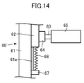
- the upper body support portion moves in the vertical direction. It is also possible to adopt an embodiment in which the upper body support portion drive mechanism is attached so as to be in a free state (19th invention). According to this, by attaching the upper body support portion to the upper body of the operator, the vertical movement of the upper body of the operator is followed without the need for an actuator for driving the upper body support portion in the vertical direction.
- the upper body support can be moved up and down.
- the upper body support portion is in the vertical direction. It is also possible to adopt an embodiment in which the upper body support portion drive mechanism is attached so as to be able to move elastically (20th invention).
- the upper body support portion is in a state of being rotatable in the roll direction of the operator, in the pitch direction of the operator, or in the roll direction and the pitch direction.
- the roll direction means the direction around the axis in the front-rear direction of the operator
- the pitch direction means the direction around the axis in the left-right direction of the operator.
- the operator smoothly tilts the upper body in the roll direction, the pitch direction, or the roll direction and the pitch direction during walking without feeling any resistance. It becomes possible. As a result, the operator can move smoothly by walking.
- control system of the present invention can be configured as a system having the control devices of the first to twenty-first inventions and the moving body.
- the control system is a control system including the control device according to any one of the fifth to eighth inventions and the thirteenth to sixteenth inventions and the moving body
- the moving body is the control system.
- a moving mechanism for a moving body configured to be able to move on the floor surface of a moving environment, and an upper body mounted on the moving mechanism for the moving body via a force detector for detecting the first reaction force. It is preferable to have a portion (22nd invention). According to this, the reaction force received from the outside world by the upper body portion of the moving body (excluding the floor reaction force received from the floor surface via the moving mechanism for the moving body) can be appropriately detected by the force detector. It will be possible.
- the upper body portion includes a cover that covers the periphery of the moving mechanism for the moving body (23rd invention). According to this, the reaction force received by the cover from an obstacle or the like in contact with the moving mechanism for the moving body can also be detected by the force detector as the first reaction force.
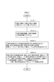
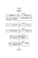
- FIG. 5 is a flowchart showing processing of the main steering control unit shown in FIG.
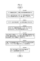
- the flowchart which shows the subroutine processing of STEP3 of FIG.
- the flowchart which shows the subroutine processing of STEP4 of FIG.
- the flowchart which shows the processing of the slave movement control part shown in FIG.
- FIG. 11A is an explanatory diagram regarding processing of the slave movement control unit
- FIG. 11B is an explanatory diagram regarding processing of the master movement control unit.
- the flowchart which shows the processing of the slave manipulator control part shown in FIG. The flowchart which shows the processing of the master manipulator control part shown in FIG.
- FIG. 5 is a perspective view showing still another example of the upper body support drive mechanism.
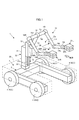
- the control device 51 for controlling the moving body 1 illustrated in FIG. 1 will be described.
- the mobile body 1 to be operated is referred to as a slave device 1
- the control device 51 for controlling the slave device 1 is referred to as a master device 51.
- the slave device 1 includes a moving mechanism 2 capable of moving on the floor surface of the operating environment thereof, and a manipulator 10 mounted on the moving mechanism 2.
- the "floor surface” is not limited to the floor surface in the usual sense, but may include the ground, the road surface, and the like.
- the "front-back direction”, “left-right direction”, and “vertical direction” of the slave device 1 are the X-axis direction, the Y-axis direction, and the Z-axis of the three-axis Cartesian coordinate system Cs shown in FIG. 1, respectively.
- the front-rear direction (X-axis direction) and the left-right direction (Y-axis direction) correspond to the "lateral direction" in the present invention.
- the moving mechanism 2 corresponds to the moving mechanism for a moving body in the present invention.
- the moving mechanism 2 includes a base 3 and a plurality of moving grounding portions 4 attached to the base 3, and a plurality of moving grounding portions 4 are provided with a space between the base 3 and the floor surface. Is grounded on the floor.
- the base 3 has a bifurcated shape (substantially U-shaped) when viewed from above, but the base 3 has an arbitrary shape. It's fine.
- the moving mechanism 2 includes, for example, four moving grounding portions 4 (1), 4 (2), 4 (3), 4 (4) as a plurality of moving grounding portions 4. Then, two moving grounding portions 4 (1) and 4 (4) are attached to both left and right sides of the front portion of the base 3, and two moving grounding portions 4 (2) are attached to both left and right sides of the rear portion of the base 3. , 4 (3)) are attached.
- Each moving ground contact portion 4 is simply described in a wheel shape in FIG. 1, but in detail, it is configured so that it can move in all directions on the floor surface while being in contact with the floor surface.
- each mobile grounding portion 4 has the same structure as the main wheel described in, for example, Japanese Patent Application Laid-Open No. 2013-237329 or US Pat. No. 9027693. Therefore, detailed description of the configuration of each mobile grounding unit 4 and its drive mechanism in the present specification will be omitted.
- the moving mechanism 2 provided with the moving grounding portion 4
- two electric motors 5a and 5b shown in FIG. 2 as power sources for the movement of each moving grounding portion 4 are shown.
- a mobile drive mechanism 5 (shown in FIG. 2) is mounted. Then, as described in Japanese Patent Application Laid-Open No. 2013-237329 or US Pat. No. 9027693, the moving drive mechanism 5 corresponding to each moving grounding portion 4 is provided from the two electric motors 5a and 5b. By transmitting power to 4, the moving ground contact portion 4 can be moved in all directions.
- each moving ground portion 4 has a speed whose speed component in the front-rear direction (X-axis direction) of the slave device 1 is proportional to the sum of the rotation speeds of the two electric motors 5a and 5b in the moving speed vector.
- the speed component in the left-right direction (Y-axis direction) is driven so as to be proportional to the difference in the rotational speeds of the two electric motors 5a and 5b.
- each movable grounding portion 4 that can move in all directions is not limited to that described in Japanese Patent Application Laid-Open No. 2013-237329 or US Pat. No. 9027693, such as Omni Wheel (registered trademark), etc. It may have the structure of. Further, the number of the moving grounding portions 4 provided in the moving mechanism 2 is not limited to 4, and may be, for example, 3 or 5 or more. Further, the power source of each mobile grounding portion 4 is not limited to the electric motors 5a and 5b, and for example, a hydraulic motor can be used.
- a manipulator 10 is attached to the base 3 via an elevating mechanism 30.
- the elevating mechanism 30 can move (elevate) in the vertical direction with respect to the support column 31 erected upward from the central portion (central portion in the left-right direction) of the rear portion of the base 3 and the support column 31.
- the slide member 32 assembled as described above is provided.
- the force detector 33 receives a reaction force (excluding the floor reaction force received from the floor surface via the moving mechanism 2) received from the outside world by the upper body portion (a portion supported on the base 3) of the slave device 1. It is for detecting, and will be referred to as an upper physical strength detector 33 hereafter.
- the upper physical strength detector 33 corresponds to the force detector of the moving body in the present invention, and the reaction force detected by the upper physical strength detector 33 corresponds to the first reaction force in the present invention.
- the upper physical strength detector 33 is composed of, for example, a 6-axis force sensor, and can detect the translational force and the moment of force as three-dimensional vectors, respectively. In the following description, the "moment of force" is simply referred to as a moment.
- the upper body portion of the slave device 1 (the portion supported on the base 3) may be hereinafter referred to as the slave upper body.
- a guide rail 31a extending in the vertical direction is attached to the front surface portion of the support column 31. Then, the slide member 32 is engaged with the guide rail 31a so as to be able to move up and down along the guide rail 31a.
- the guide mechanism may be different from the above.
- the elevating mechanism 30 includes a slide drive actuator 36 (shown in FIG. 2) which is an actuator for elevating and lowering the slide member 32 with respect to the support column 31.
- the slide drive actuator 36 is composed of, for example, an electric motor.
- the slide drive actuator 36 applies a driving force for raising and lowering the slide member 32 with respect to the support column 31 to the slide member 32 via, for example, a rotation / linear motion conversion mechanism (not shown) such as a ball screw mechanism. It is attached to the support column 31 or the slide member 32 so as to raise and lower the slide member 32.
- the slide drive actuator 36 is not limited to the electric motor, and for example, a hydraulic motor or a hydraulic cylinder can be used.
- the manipulator 10 corresponds to the working manipulator in the present invention, and is attached to the slide member 32 in the present embodiment.
- the manipulator 10 includes a pair of left and right hands 21L and 21R, and these two hands 21L and 21R are connected to the slide member 32 via a plurality of joints.
- the manipulator 10 is attached to, for example, a first link 13 extending from a slide member 32 via a first joint mechanism 12 and a tip portion of the first link 13 via a second joint mechanism 14.
- each force detector 22 (hereinafter referred to as a hand force detector 22) is composed of, for example, a 6-axis force sensor, similarly to the upper physical strength detector 33.
- Each hand 21 may include a mechanism for gripping an object, a mechanism for detachably adsorbing an object, an electric tool, or the like.
- Each of the joint mechanisms 12, 14, 16, 18, and 20 is a joint mechanism having a known structure, and is composed of one or a plurality of joints so as to have, for example, one or more degrees of freedom of rotation.
- joint means a joint which has uniaxial rotational degrees of freedom unless otherwise specified.
- each of the left and right hands 21 has 7 or more degrees of freedom of movement.
- the third joint mechanism 16 corresponding to the shoulder joints of the left and right arms of the manipulator 10 the fourth joint mechanism 18 corresponding to the elbow joint, and the fifth joint mechanism 20 corresponding to the wrist joint have three axes, respectively.
- the degree of freedom of rotation of 1 axis can be configured to have a degree of freedom of rotation of 3 axes.
- each joint actuator 24 is composed of, for example, an electric motor.
- each hand 21 may be connected to the slide member 32 via, for example, a three-axis slide mechanism.
- each joint actuator 24 is not limited to an electric motor, and can be configured by, for example, a hydraulic motor or a hydraulic actuator such as a hydraulic cylinder.
- the slave device 1 of the present embodiment is further equipped with a cover 26 for preventing an external object from hitting the moving mechanism 2.
- the cover 26 is formed below the manipulator 10 so as to cover the entire circumference and the upper surface of the moving mechanism 2, as shown by a two-dot chain line in FIG. 1, for example, and a support column is provided via an appropriate mounting member (not shown). It is fixed at 31.
- the slave device 1 of the present embodiment it is prevented that an object or the like existing in the outside world directly hits the moving mechanism 2 while the slave device 1 is moving.
- the cover 26 receives a reaction force (external force such as a contact reaction force) from the outside world, the reaction force is transmitted from the cover 26 to the upper physical strength detector 33 via the support column 31.
- the reaction force (external force such as contact reaction force) received by the manipulator 10 from the outside world is transmitted from the manipulator 10 to the upper physical strength detector 33 via the slide member 32 and the support column 31. It is supposed to be transmitted.
- the upper physical strength detector 33 removes the floor reaction force received from the floor surface by the slave upper body via the moving mechanism 2, and the slave device 1 can detect the reaction force received by the slave upper body from the outside world. It is installed in.
- the slave upper body corresponding to the upper body portion of the moving body in the present invention is composed of the elevating mechanism 30, the manipulator 10, and the cover 26.
- the slave device 1 is further equipped with a communication device 40 for wirelessly communicating with the master device 51 and a control device 41 having a function of controlling the operation of the slave device 1.
- a communication device 40 for wirelessly communicating with the master device 51 and a control device 41 having a function of controlling the operation of the slave device 1.
- the motor rotation detection as a detector for detecting the driving state of each moving grounding portion 4 by each moving driving mechanism 5.
- a device 27, a joint displacement detector 28 as a detector for detecting the operating state of the manipulator 10, and a slide displacement detector 29 for detecting the displacement (vertical position) of the slide member 32 are mounted. There is.
- the motor rotation detector 27 determines, for example, the rotation angle of the rotation shafts (or rotating members that rotate in conjunction with the rotation shafts) of the electric motors 5a and 5b for each movement drive mechanism 5 in the driving state of the movement drive mechanism 5. It is a detector that can be detected as a state quantity indicating. Further, the joint displacement detector 28 detects, for example, the displacement (rotation angle) of each joint constituting each joint mechanism 12, 14, 16, 18, 20 of the manipulator 10 as a state quantity indicating the operating state of the manipulator 10. It is a possible detector. Each of the motor rotation detector 27 and the joint displacement detector 28 may be composed of, for example, a rotary encoder, a resolver, a potentiometer, or the like.
- the slide displacement detector 29 is composed of, for example, a known contact type or non-contact type displacement sensor. Further, for example, when the power transmission mechanism from the slide drive actuator 36 to the slide member 32 is configured so that the displacement of the slide member 32 is proportional to the rotation angle of the rotation axis of the slide drive actuator 36, the said.
- a detector capable of detecting the rotation angle of the rotation axis of the slide drive actuator 36 (or a rotating member that rotates in conjunction with the rotation axis) can also be used as a slide displacement detector. In this case, the slide displacement detector 29 may be the same detector as the motor rotation detector 27.
- the slave device 1 is provided with a plurality of movement drive mechanism 5, motor rotation detector 27, joint actuator 24, joint displacement detector 28, and hand force detector 22, but in FIG. 2, each of them is provided. Only one is typically listed.
- the control device 41 is composed of one or more electronic circuit units including, for example, a microcomputer, a memory, an interface circuit, and the like. Although detailed description will be described later, command data indicating the operation target (target movement) of the slave upper body and each hand 21 is input from the master device 51 to the control device 41 via the communication device 40, and the slave The detection data of each detector mounted on the device 1 (upper body force detector 33, each motor rotation detector 27, slide displacement detector 29, each joint displacement detector 28, and each hand force detector 22) is input. Will be done.
- control device 41 moves the upper body of the slave device 1 as a function realized by both or one of the mounted hardware configuration and the program (software configuration), and the electric motor 5a of each movement drive mechanism 5 A function as a slave movement control unit 42 that controls via the 5b and the slide drive actuator 36, and a function as a slave manipulator control unit 43 that controls the operation of each hand 21 of the manipulator 10 via each joint actuator 24.
- the control device 41 can output (transmit) data indicating the actual operating state of the slave device 1 (hereinafter referred to as an actual slave state) to the master device 51 via the communication device 40.
- slave may be added to the beginning of the name of the component of the slave device 1 as appropriate.
- the base 3 of the slave device 1 may be referred to as the slave base 3.
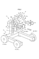
- the configuration of the master device 51 will be described with reference to FIGS. 3 to 5.
- the "front-back direction”, “horizontal direction”, and “vertical direction” of the master device 51 are the X-axis direction and the Y-axis direction of the 3-axis Cartesian coordinate system Cm shown in FIG. 3 or 4, respectively. , Z-axis direction.
- the front-rear direction (X-axis direction) and the left-right direction (Y-axis direction) correspond to the "lateral direction” in the present invention.
- the reference code of the component on the left side and the reference code of the component on the right side are appropriately designated as necessary. "L” and "R” are added.
- the master device 51 corresponds to the control device in the present invention.
- the master device 51 includes a moving mechanism 52 capable of moving on the floor surface of the operating environment of the operator P (shown in FIG. 4) operating the slave device 1, and an upper body support mounted on the upper body of the operator P.
- a unit 65 and a manipulator 70 for the operator P to operate the slave manipulator 10 are provided.
- the moving mechanism 52 has the same configuration as the slave moving mechanism 2, and similarly to the slave moving mechanism 2, the base 53 and a plurality of (four) moving grounding portions attached to the base 53. It includes 54 (54 (1), 54 (2), 54 (3), 54 (4)). Further, although detailed illustration is omitted, the moving mechanism 52 includes a moving drive mechanism 55 having electric motors 55a and 55b and a motor rotation detector as components corresponding to the moving grounding portions 54, as shown in FIG. 87 is provided in the same manner as the slave moving mechanism 2. The electric motors 55a and 55b correspond to the first actuator in the present invention.
- the upper body support portion 65 and the manipulator 70 are attached to the base 53 via the elevating mechanism 60.
- the elevating mechanism 60 together with the moving mechanism 52, constitutes the upper body support portion driving mechanism in the present invention.
- the elevating mechanism 60 can move (elevate) in the vertical direction with respect to the column 61 erected upward from the central portion (central portion in the left-right direction) of the rear portion of the base 53 and the column 61.
- the slide member 62 assembled as described above is provided.
- the support column 61 is fixed to the base 53.
- a guide rail 61a extending in the vertical direction is attached to the front surface portion of the support column 61. Then, the slide member 62 is engaged with the guide rail 61a so as to be able to move up and down along the guide rail 61a.
- the guide mechanism may be different from the above.
- the master device 51 is equipped with a slide drive actuator 66 (shown in FIG. 5), which is an actuator for raising and lowering the slide member 62 with respect to the support column 61.
- the slide drive actuator 66 corresponds to the second actuator in the present invention, and is composed of, for example, an electric motor.
- the slide drive actuator 66 raises and lowers the slide member 62 via a power transmission mechanism similar to the power transmission mechanism from the slide drive actuator 36 of the slave device 1 to the slide member 32, for example.
- the slide drive actuator 66 is not limited to an electric motor, and for example, a hydraulic motor or a hydraulic cylinder can be used.
- the upper body support portion 65 is configured so that it can be aligned with a predetermined portion of the upper body of the operator P, for example, the outer circumference of the waist portion from the back side.
- the upper body support portion 65 is composed of a plate-shaped member formed in a substantially semicircular arc shape (or U shape). The upper body support portion 65 is attached to the slide member 62 via a support shaft 63 and a force detector 64.
- the support shaft 63 is attached to the slide member 62 via a force detector 64 with its axis oriented in the front-rear direction (X-axis direction).
- the force detector 64 (hereinafter referred to as the upper body strength detector 64) is a detector for detecting the reaction force (contact reaction force) received by the upper body support portion 65 from the upper body of the operator P, and is on the slave. Similar to the physical strength detector 33, it is composed of, for example, a 6-axis force sensor.
- the upper body support portion 65 has a central portion between both ends attached to the support shaft 63.
- the upper body support portion 65 allows the slide member 62 and the upper body force detector 64 to freely rotate around the axis of the support shaft 63 (in other words, in the roll direction). Is supported by.
- the upper body support portion 65 When the operator P operates the slave device 1, the upper body support portion 65 is arranged so as to be along the outer periphery of the waist portion of the upper body of the operator P from the back side thereof, as shown in FIG. A flexible belt 65x (shown by a two-dot chain line in FIG. 4) is connected to both ends of the upper body support portion 65 so as to be arranged along the outer circumference of the waist portion of the operator P on the front surface side. Will be done.
- the upper body support portion 65 and the belt 65x surround the waist portion of the upper body of the driver P, and the upper body support portion 65 is attached to the waist portion of the driver P via the belt 65x.
- the upper body support portion 65 is mounted so as not to be displaced relative to the waist portion of the operator P.
- the upper body support portion 65 can adjust the height (position in the vertical direction) of the upper body support portion 65 by appropriately moving the slide member 62 up and down.
- an elastic member such as a pad (not shown) is attached to the inner peripheral surface of the upper body support portion 65, and the elastic member is brought into contact with the periphery of the waist portion of the operator P.
- the upper body support portion 65 In the state where the upper body support portion 65 is attached to the waist of the operator P in this way, the upper body support portion 65 and the moving mechanism 52 can move together with the operator P as the operator P moves (walks). become. In this case, the pilot P can tilt his upper body back and forth and left and right. Further, the reaction force received by the upper body support portion 65 from the lumbar region of the operator P is detected by the upper body force detector 64.
- the manipulator 70 corresponds to the manipulator for maneuvering in the present invention, and is attached to the slide member 62 in the present embodiment.
- the manipulator 70 includes two pairs of left and right hands 81L and 81R that can be attached to the left and right wrists (or a portion in the vicinity thereof) of the operator P via a belt (not shown), and the plurality of these hands 81L and 81R are present. It is connected to the slide member 62 via a joint.
- the connection structure between the hands 81L and 81R and the slide member 62 is the same as, for example, the slave manipulator 10. That is, the manipulator 70 has a first link 73 extending from the slide member 62 via the first joint mechanism 72 on the upper side of the upper physical strength detector 64, and a second joint mechanism 74 at the tip of the first link 73. A pair of left and right second links 75L and 75R attached via the second links 75L and 75R, and third links 77L and 77R attached to the tips of the second links 75L and 75R via the third joint mechanisms 76L and 76R, respectively.
- the tips of the third links 77L and 77R are provided with the fourth links 79L and 79R attached via the fourth joint mechanisms 78L and 78R, respectively, and the fifth joint mechanism is provided at the tips of the fourth links 79L and 79R, respectively.
- the hands 81L and 81R are attached via the 80L and 80R and the force detectors 82L and 82R, respectively.
- each force detector 82 is for detecting the reaction force (contact reaction force) received by each hand 81 from the tip end side portion (hand or the like) of each arm of the operator P, and detects the physical strength of the slave.
- the vessel 33 and the like it is composed of, for example, a 6-axis force sensor.
- each force detector 82 will be referred to as a hand force detector 82.
- the resultant force of the reaction forces detected by the left and right hand force detectors 82L and 82R respectively corresponds to the second reaction force in the present invention.
- the manipulator 70 having the above configuration has, similarly to the slave manipulator 10, each joint (one-axis rotation degree of freedom) constituting each joint mechanism 72, 74, 76, 78, 80.
- a plurality of joint actuators 84 (shown in FIG. 5) for driving each of the joints having the joints) are mounted.
- Each joint actuator 84 is composed of, for example, an electric motor.
- the manipulator 70 is not limited to the rotary type joint, but may include a linear motion type joint. Further, the connection structure between each hand 81 and the slide member 62 may be different from that of the slave manipulator 10. Each hand 21 may be connected to the slide member 62 via, for example, a three-axis slide mechanism. Further, each joint actuator 84 is not limited to an electric motor, and can be configured by, for example, a hydraulic motor or a hydraulic actuator such as a hydraulic cylinder.
- the master device 51 is further equipped with a communication device 90 for wirelessly communicating with the slave device 1 and a control device 91 having a function of controlling the operation of the master device 51.
- a communication device 90 for wirelessly communicating with the slave device 1 and a control device 91 having a function of controlling the operation of the master device 51.
- the motor rotation detection as a detector for detecting the driving state of each moving ground contact portion 54 by each moving driving mechanism 55.
- a device 87, a joint displacement detector 85 as a detector for detecting the operating state of the manipulator 70, and a slide displacement detector 89 for detecting the displacement (vertical position) of the slide member 62 are mounted. There is.
- the motor rotation detector 87 determines the rotation angle of each rotation axis (or a rotation member that rotates in conjunction with the rotation axis) of the electric motors 55a and 55b for each movement drive mechanism 55. It is a detectable detector.
- the joint displacement detector 85 is a detector capable of detecting the displacement (rotation angle) of each joint constituting each joint mechanism 72, 74, 76, 78, 80 of the manipulator 70.
- the same configuration of the slave motor rotation detector 27 and the slave joint displacement detector 28 can be used.
- the slide displacement detector 89 may also have the same configuration as the slave slide displacement detector 29.
- the master device 51 is provided with a plurality of movement drive mechanism 55, motor rotation detector 87, joint actuator 84, joint displacement detector 85, and hand force detector 82, but in FIG. 5, each of them is provided. Only one is typically listed.
- the control device 91 is composed of one or more electronic circuit units including, for example, a microcomputer, a memory, an interface circuit, and the like. Although detailed description will be described later, data indicating the actual slave state is input from the slave device 1 to the control device 91 via the communication device 90, and the upper physical strength detector 64 of the master device 51 and each hand force. The detection data of the detector 82, each motor rotation detector 87, and each joint displacement detector 85 are input.
- the control device 91 generates the overall operation target (target motion) of the slave device 1 and the master device 51 as a function realized by both or one of the mounted hardware configuration and the program (software configuration).
- the manipulator 70 has a function as a master manipulator control unit 93 that controls the operation of the manipulator 70 via each joint actuator 84.
- the control device 91 can output (transmit) command data indicating the operation target (target motion) of the slave device 1 to the slave device 1 via the communication device 90.
- master may be added to the beginning of the name of the component of the master device 51 as appropriate.
- the base 53 of the master device 51 may be referred to as the master base 53.
- the main steering control unit 94 of the master device 51 has a function as a movement command determining unit in the present invention, and also has a function as a first control unit in the present invention together with the master movement control unit 92.
- the name of an arbitrary state quantity with "target” added to the beginning, or the reference code of the state quantity with the subscript “_aim” added means the target value of the state quantity.
- the reference code with " ⁇ " at the beginning is a reference code representing a vector (vertical vector).
- a "slave” may be added at the beginning of the name of the state quantity or between the name of the state quantity and the "actual” or “target”. .. This also applies to the state quantity associated with the master device 51.
- the "movement" of an arbitrary object means a state quantity of any one of the position, velocity (translational velocity), posture angle, and angular velocity of the object, or a set of two or more state quantities.
- the posture angle is an angle (azimuth) representing the direction of the object as seen in a certain coordinate system.
- the posture angles are represented by, for example, Euler angles.
- the posture angle may be simply referred to as a posture.
- the main control unit 94 sequentially executes the processes shown in the flowchart of FIG. 6 at a predetermined control process cycle.
- the main control unit 94 acquires (receives) data indicating the actual slave state as the actual operating state of the slave device 1 from the slave control device 41 via the communication devices 40 and 90.
- the actual slave upper body reaction force which is the actual reaction force that the slave upper body (upper body of the slave device 1) receives from the outside world other than the floor reaction force
- the slave upper body The actual slave upper body movement, which is the actual movement of, the actual slave hand movement, which is the actual movement of each slave hand 21, and the actual slave hand reaction force, which is the reaction force that each slave hand 21 actually receives from the outside world. included.
- the actual slave upper body reaction force is the resultant force of the actual reaction force received from the outside world by the slave upper body via the support column 31, the cover 26, or the manipulator 10. Further, each of the actual slave upper body reaction force and the left and right actual slave hand reaction force is composed of a pair of translational force and moment. Then, each of the translational force and the moment of the actual slave upper body reaction force acquired by the main control unit 94 in STEP 1 is a global coordinate system arbitrarily designed and set with respect to the operating environment of the slave device 1 (the operation). It is represented as a three-dimensional vector as seen in a three-dimensional coordinate system fixed to the floor of the environment; hereinafter referred to as a slave-side global coordinate system).
- the respective moments of the actual slave upper body reaction force and the left and right actual slave hand reaction forces are, more specifically, at the predetermined reference points (hereinafter referred to as slave reference points Qs) set for the slave device 1. It is a moment around.
- the slave reference point Qs can be appropriately set in consideration of the structure of the slave device 1 and the like.
- the master moving mechanism 52 and the slave moving mechanism 2 have substantially the same or substantially similar shapes.
- the positional relationship between the slave reference point Qs and the slave moving mechanism 2 and the positional relationship between the reference point Qm and the master moving mechanism 52, which will be described later in the master device 51, are substantially the same or similar to each other.
- the slave reference point Qs can be set so as to be.
- the slave reference points Qs shown in FIG. 11A exemplify the reference points set from such a viewpoint. Note that in FIG. 11A, the manipulator 10 is not shown.
- the moments of the left and right real slave hand reaction forces are set to the predetermined reference points set for the respective slave hands 21L and 21R (hereinafter, the slave hand reference). It is converted into moments around points Qhs_L and Qhs_R), and the moments of the left and right real master hand reaction forces are converted to predetermined reference points (hereinafter referred to as master hands) set for the respective master hands 81L and 81R. It is preferable to convert it into a moment around the reference point (referred to as Qhm_L and Qhm_R). This transformation makes the bilateral control characteristics more appropriate.
- ⁇ F_sb_act and ⁇ M_sb_act are used as reference codes for the translational force and the moment of the actual slave upper body reaction force, respectively.
- ⁇ F_sh_act_L and ⁇ M_sh_act_L are used as reference codes for the translational force and moment of the actual slave hand reaction force on the left side
- ⁇ F_sh_act_R is used as the reference code for the translational force and moment of the real slave hand reaction force on the right side.
- ⁇ Use M_sh_act_R Use M_sh_act_R.
- ⁇ F_sh_act ⁇ F_sh_act_L + ⁇ F_sh_act_R
- ⁇ M_sh_act ⁇ M_sh_act_L + ⁇ M_sh_act_R.
- the actual slave upper body motion includes the position of the slave upper body as seen in the above slave-side global coordinate system ⁇ P_sb_act, translation velocity ⁇ V_sb_act, posture angle ⁇ ⁇ _sb_act, and angular velocity ⁇ ⁇ _sb_act.
- the real slave hand motion includes the position ⁇ P_sh_act, translational velocity ⁇ V_sh_act, attitude angle ⁇ ⁇ _sh_act, and angular velocity ⁇ ⁇ _sh_act of each slave hand 21 as seen in the slave-side global coordinate system.
- the position of the slave upper body ⁇ P_sb_act is the position of the representative point set (defined) in advance with respect to the slave upper body, for example, the position of the slave reference point Qs.
- the vertical axis component (yaw direction component) of the slave upper body posture angle ⁇ ⁇ _sb_act is the vertical axis component (yaw direction component) of the slave base 3 posture angle. Ingredient) is considered to match.
- all or part of the actual slave state output from the slave control device 41 to the main control control unit 94 is the local coordinate system set for the slave device 1 (for example, the slave upper body coordinates described later). It may be the state quantity seen in the system Cs).
- the main control unit 94 sees the actual slave state (actual slave state as seen in the local coordinate system) given by the slave control device 41 in the slave-side global coordinate system as the actual slave state. Convert to and get.
- the main maneuvering control unit 94 may omit to acquire the posture angle and the angular velocity around the lateral axis among the posture angle ⁇ ⁇ _sb_act and the angular velocity ⁇ ⁇ _sb_act of the actual slave upper body movement.
- the moment of the reaction force of the actual slave upper body ⁇ M_sb_act it is possible to omit acquiring the moment around the axis in the lateral direction.
- the main manipulator control unit 94 acquires data indicating the actual master state, which is the actual operating state of the master device 51, from the master movement control unit 92 and the master manipulator control unit 93.
- the actual upper body support portion reaction force which is the actual reaction force received by the upper body support portion 65 from the operator P, and the actual movement of the upper body support portion 65.
- Each of the above-mentioned actual body support reaction force and the left and right actual master hand reaction force is composed of a pair of translational force and moment.
- Each of these translational forces and moments is a global coordinate system arbitrarily designed and set with respect to the operating environment of the master device 51 (a three-dimensional coordinate system fixed to the floor of the operating environment. , Represented as a three-dimensional vector as seen in the master-side global coordinate system).
- the respective moments of the reaction force of the actual body support portion and the reaction force of the left and right actual master hands are, more specifically, a predetermined reference point set for the master device 51 (hereinafter referred to as a master reference point Qm).
- a master reference point Qm is an intermediate point between the left and right side portions of the upper body support portion 65 on the axial center of the support shaft 63 (the operator wearing the upper body support portion 65). It can be set at a point near the center of the waist of P). Note that FIG. 11B omits the illustration of the master manipulator 70.
- ⁇ F_mb_act and ⁇ M_mb_act will be used as reference codes to represent the translational force and moment of the reaction force of the actual body support, respectively.
- ⁇ F_mh_act_L and ⁇ M_mh_act_L are used as reference codes for the translational force and moment of the actual master hand reaction force on the left side
- ⁇ F_mh_act_R is used as the reference code for the translational force and moment of the actual master hand reaction force on the right side.
- ⁇ Use M_mh_act_R Use M_mh_act_R.
- the resultant force of the left and right real master hand reaction forces is called the actual master hand resultant force, and "L” and “R” are not added as reference codes to represent the translational force and moment of the actual master hand resultant force.
- F_mh_act and ⁇ M_mh_act Use F_mh_act and ⁇ M_mh_act.
- ⁇ F_mh_act ⁇ F_mh_act_L + ⁇ F_mh_act_R
- ⁇ M_mh_act ⁇ M_mh_act_L + ⁇ M_mh_act_R.
- the actual body support movement includes the position ⁇ P_mb_act, translation speed ⁇ V_mb_act, posture angle ⁇ ⁇ _mb_act, and angular velocity ⁇ ⁇ _mb_act of the upper body support 65 as seen in the above master-side global coordinate system.
- the actual master hand motion includes the position ⁇ P_mh_act, translational velocity ⁇ V_mh_act, attitude angle ⁇ ⁇ _mh_act, and angular velocity ⁇ ⁇ _mh_act of each master-hand 81 as seen in the master-side global coordinate system.
- the position ⁇ P_mb_act of the upper body support portion 65 is a position of a representative point preset with respect to the upper body support portion 65, for example, a position of the master reference point Qm. Further, in the present embodiment, the posture angle ⁇ ⁇ _mb_act of the upper body support portion 65 is considered to match the posture angle of the master base 53.
- all or part of the actual master state output from the master movement control unit 92 and the master manipulator control unit 93 to the main control control unit 94 is a local coordinate system set for the master device 50 (for example,). , It may be the state quantity seen in the master upper body coordinate system Cm) described later.
- the main manipulator control unit 94 sets the real slave state (real slave state as seen in the local coordinate system) given by the master movement control unit 92 or the master manipulator control unit 93 in STEP 2 to the master side global coordinates. Convert to the actual master state seen in the system and acquire it.
- the main maneuvering control unit 94 may omit to acquire the posture angle and the angular velocity around the axis in the lateral direction among the posture angle ⁇ ⁇ _mb_act and the angular velocity ⁇ ⁇ _mb_act of the actual body support movement.
- Actual body support part reaction force moment ⁇ Of M_mb_act it is possible to omit to acquire the moment around the axis in the lateral direction.
- the main maneuvering control unit 94 executes the processing of the upper body side bilateral control which is the bilateral control regarding the operation of the upper body of the master device 51 and the upper body of the slave device 1.
- This upper body side bilateral control process is executed as shown in the flowchart of FIG.
- the main control unit 94 calculates the upper body reaction force deviation.
- the upper body reaction force deviation is the upper body reaction force translational force deviation ⁇ Efb, which is the upper body reaction force deviation related to the translational force, and the upper body reaction force moment deviation ⁇ Efb, which is the upper body reaction force deviation related to the moment. It is composed of Emb.
- the upper body reaction force translational force deviation ⁇ Efb is, for example, the translational force of the actual master hand resultant force ⁇ F_mh_act, the translational force of the actual slave upper body reaction force ⁇ F_sb_act, and the translational force of the actual slave hand resultant force ⁇ F_sh_act. It is defined as an index value indicating the degree of deviation (deviation degree) of the mutual relationship between one or more translational forces and the translational force of the reaction force of the actual body support ⁇ F_mb_act from a predetermined target relationship.
- the upper body reaction force moment deviation ⁇ Emb is one of, for example, the actual master hand resultant force moment ⁇ M_mh_act, the actual slave upper body reaction force moment ⁇ M_sb_act, and the actual slave hand resultant force moment ⁇ M_sh_act. It is defined as an index value indicating the degree of deviation (deviation degree) from the predetermined target relationship between the above moment and the moment of the reaction force of the actual body support ⁇ M_mb_act.
- the left and right real master hand reaction forces and the real slave hand reaction forces are proportional to each other at a predetermined ratio for each of the translational force and the moment by the hand-side bilateral control described later.
- the operations of the left and right master hands 81 and slave hands 21 are controlled.
- one of the translational force of the actual master hand resultant force ⁇ F_mh_act and the translational force of the actual slave hand resultant force ⁇ F_sh_act becomes the dependent variable of the other, and the moment of the actual master hand resultant force ⁇ M_mh_act and the moment of the actual slave hand resultant force ⁇ M_sh_act. Is the other dependent variable.
- the upper body reaction force translational force deviation ⁇ Efb is set to, for example, the translational force ⁇ F_mh_act of the actual master hand resultant force and the translational force ⁇ F_sh_act of the actual slave hand resultant force, for example, ⁇ F_mh_act and the actual slave. It is defined by the following equation (1a) as an index value expressed by a function of the translational force of the body reaction force ⁇ F_sb_act and the translational force of the actual body support part reaction force ⁇ F_mb_act.
- the upper body reaction force moment deviation ⁇ Emb for example, the moment of the actual master hand resultant force ⁇ M_mh_act and the moment of the actual slave hand resultant force ⁇ M_sh_act, for example ⁇ M_mh_act, and the moment of the actual slave upper body reaction force ⁇ M_sb_act
- ⁇ M_mh_act the moment of the actual master hand resultant force ⁇ M_mh_act
- ⁇ M_sb_act for example, the moment of the actual slave upper body reaction force ⁇ M_sb_act
- Ratio_fsb, Ratio_fmh, Ratio_msb, and Ratio_mmh in the equations (1a) and (1b) are coefficients representing the respective return rates of ⁇ F_sb_act, ⁇ F_mh_act, ⁇ M_sb_act, and ⁇ M_mh_act with respect to the pilot P, respectively. It is set to a predetermined value set in advance.
- the coefficient may be either a scalar or a diagonal matrix.
- the coefficients Ratio_fsb and Ratio_msb of the second term on the right side of each of the equations (1a) and (1b) are set to the same values, and the coefficients Ratio_fmh and Ratio_mmh of the third term are set to the same values. Will be done. However, it is also possible to set Ratio_fsb and Ratio_msb to different values, or to set Ratio_fmh and Ratio_mmh to different values.
- Ratio_fsb and Ratio_fmh in the formula (1a) it is also possible to set one or both of Ratio_fsb and Ratio_fmh in the formula (1a) to zero, and set one or both of Ratio_msb and Ratio_mmh in the formula (1a) to zero, which will be described later. .. Therefore, in the present embodiment, it is assumed that Ratio_fsb ⁇ 0, Ratio_fmh ⁇ 0, Ratio_msb ⁇ 0, and Ratio_mmh ⁇ 0.
- the main control unit 94 is the resultant force of the actual slave upper body reaction force ( ⁇ F_sb_act, ⁇ M_sb_act) acquired in STEP1 and the left and right actual master hand reaction forces acquired in STEP2. From the actual master hand resultant force ( ⁇ F_mh_act, ⁇ M_mh_act) and the actual upper body support reaction force ( ⁇ F_mb_act, ⁇ M_mb_act) acquired in STEP 2, the upper body reaction force deviation according to the above equations (1a) and (1b). Calculate ( ⁇ Efb, ⁇ Emb).
- the upper body reaction force deviation ( ⁇ Efb, ⁇ Emb) is calculated using the actual slave hand resultant force ( ⁇ F_sh_act, ⁇ M_sh_act) proportional to this instead of the actual master hand resultant force ( ⁇ F_mh_act, ⁇ M_mh_act). It is also possible to do.
- the main maneuvering control unit 94 calculates the upper body position / posture deviation.
- the upper body position and posture deviations are the upper body position deviation ⁇ Epb regarding the positions of the upper body support 65 and the slave upper body, and the upper body posture deviation ⁇ Epb regarding the respective posture angles of the upper body support 65 and the slave upper body. It is composed of Ethb.
- the upper body position deviation ⁇ Epb is an index value indicating the degree of deviation (dissociation degree) of the mutual relationship between the position of the upper body support portion 65 ⁇ P_mb_act and the position of the slave upper body ⁇ P_sb_act from a predetermined target relationship. Is defined as.
- the upper body posture deviation ⁇ Ethb determines the degree of deviation (degree of deviation) from the predetermined target relationship between the posture angle ⁇ ⁇ _mb_act of the upper body support portion 65 and the posture angle ⁇ ⁇ _sb_act of the slave upper body. It is defined as an index value to represent.
- the position of the slave upper body ⁇ P_sb_act and the posture angle ⁇ ⁇ _sb_act are, for example, the position of the upper body support portion 65 ⁇ P_mb_act multiplied by (1 / Ratio_psb) and above.
- the posture angle of the body support portion 65 is controlled by multiplying the posture angle ⁇ ⁇ mb_act by (1 / Ratio_thsb).
- the index values defined by the right sides of the following equations (2a) and (2b) are used as the upper body position deviation ⁇ Epb and the upper body posture deviation ⁇ Rthb, respectively.
- ⁇ Ethb ⁇ ⁇ _mb_act-Ratio_thsb * ⁇ ⁇ _sb_act ...... (2b)
- the coefficients Ratio_psb and Ratio_thsb of the equations (2a) and (2b) are predetermined coefficients (scalar or diagonal matrix) set in advance, respectively. Further, in the present embodiment, Ratio_psb and Ratio_thsb are set to the same values. However, it is also possible to set Ratio_psb and Ratio_thsb to different values.
- 1 / A means an inverse matrix of A.
- the coefficient Ratio_psb is a diagonal matrix
- (1 / Ratio_psb) is an inverse matrix of Ratio_psb.
- the main maneuvering control unit 94 has the position ⁇ P_sb_act and the posture angle ⁇ ⁇ _sb_act of the actual slave upper body movements acquired in STEP1 and the actual body support part movements acquired in STEP2. From the position ⁇ P_mb_act and the posture angle ⁇ ⁇ _mb_act, the upper body position / posture deviation ( ⁇ Epb, ⁇ Ethb) is calculated according to the above equations (2a) and (2b).
- the main maneuvering control unit 94 sets the target values of the translational acceleration and the angular acceleration of the upper body support portion 65 so as to converge the upper body reaction force deviation and the upper body position / attitude deviation to zero.
- Target upper body support translational acceleration ⁇ Acc_mb_aim and target upper body support angular acceleration ⁇ ⁇ _mb_aim, and target slave upper body translational acceleration and angular acceleration, which are the target values of each of the slave upper body translational acceleration and angular acceleration ⁇ Acc_sb_aim and target slave Body angular acceleration ⁇ ⁇ _sb_aim is determined.
- the target upper body support part translational acceleration ⁇ Acc_mb_aim and the target slave upper body translational acceleration ⁇ Acc_sb_aim should converge the upper body reaction force translational force deviation ⁇ Efb and the upper body position deviation ⁇ Epb to zero, respectively.
- the target upper body support angular acceleration ⁇ ⁇ _mb_aim and the target slave upper body angular acceleration ⁇ ⁇ _sb_aim are determined so that the upper body reaction force moment deviation ⁇ Emb and the upper body posture deviation ⁇ Ethb converge to zero, respectively. ..
- the coefficient representing the rigidity between the upper body support portion 65 and the operator P is expressed as Kmb
- the coefficient representing the rigidity between the slave upper body and the external object (excluding the floor surface) is expressed as Ksb
- the actual body support is expressed. It can be considered that the relation of the following equation (3a) is approximately established between the translational force ⁇ F_mb_act ⁇ of the partial reaction force and the position ⁇ P_mb_act in the actual body support movement. Similarly, it can be considered that the relation of the following equation (4a) is approximately established between the translational force ⁇ F_sb_act ⁇ of the reaction force of the actual slave upper body and the position ⁇ P_sb_act of the actual slave upper body movement.
- the coefficients Kfmb and Kfsb are coefficients (scalar or diagonal matrix) of predetermined values corresponding to the so-called spring constants, respectively. Further, ⁇ Cfmb and ⁇ Cfsb are constant vectors (vectors in which each component is a constant of a certain value).
- ⁇ ua and ⁇ va are defined by the following equations (6a) and (7a), respectively.
- the second-order differential value of the upper body reaction force translational force deviation ⁇ Efb is a target value satisfying the relational expression of the following equation (10a) ⁇ It should match Efb_dotdot_aim.
- the second derivative value of the upper body position deviation ⁇ Epb matches the target value ⁇ Epb_dotdot_aim that satisfies the relational expression of the following equation (11a). Good.
- the coefficients Kfbp and Kfbv on the right side of the equation (10a) are gains (scalar or diagonal matrix) of predetermined values, and ⁇ Efb_dot is the first derivative value (time change rate) of ⁇ Efb. Further, the coefficients Kpbp and Kpbv on the right side of the equation (11a) are gains (scalar or diagonal matrix) of predetermined values, and ⁇ Epb_dot is the first derivative value (time change rate) of ⁇ Epb.
- the reference code with "_dot” added represents the first derivative (temporal change rate) of the state quantity indicated by the reference code with "_dot” removed, and "_dotdot” is added.
- the reference code represents the second derivative of the state quantity indicated by the reference code with "_dotdot” removed.
- the target value of ⁇ ua_dotdot for converging the upper body reaction force translational force deviation ⁇ Efb to zero is ⁇ ua_dotdot_aim
- the target value of ⁇ va_dotdot for converging the upper body position deviation ⁇ Epb to zero is ⁇ va_dotdot_aim.
- Equation (16a), (17a), (20a), and (21a) are equations for determining the target upper body support portion translational acceleration ⁇ Acc_mb_aim and the target slave upper body translational acceleration ⁇ Acc_sb_aim.
- ⁇ F_mh_ dotdot_act obtained by the second derivative of F_mh_act
- ⁇ ua_dotdot_aim is calculated according to equation (16a).
- ⁇ va_dotdot_aim is calculated according to the equation (17a).
- the target upper body support portion translational acceleration ⁇ Acc_mb_aim and the target slave upper body translational acceleration ⁇ Acc_sb_aim are calculated according to the equations (20a) and (21a).
- ⁇ Acc_mb_aim and ⁇ Acc_sb_aim are determined so that the upper body reaction force translational force deviation ⁇ Efb and the upper body position deviation ⁇ Epb converge to zero.
- ⁇ va_dotdot_aim can also be calculated according to the equation (23a). In this case, it is not necessary to calculate the upper body reaction force translational force deviation ⁇ Efb and the upper body position deviation ⁇ Epb in STEP3-1 and 3-2, respectively.
- a relational expression ( ⁇ ua_dotdot_aim, ⁇ va_dotdot_aim) in which the set of the formulas (16a) and (17a) or the set of the formulas (22a) and (23a) and the set of the formulas (20a) and (21a) are integrated is included. It is also possible to calculate ⁇ Acc_mb_aim and ⁇ Acc_sb_aim by the relational expression).
- the Kmmb of the formulas (3b) and (6b) and the coefficient Kmsb of the formulas (4b) and (6b) are predetermined values representing the rigidity, respectively, like the coefficient Kfmb of the formula (3a) and the coefficient Kfsb of the formula (4a). It is a coefficient of value (scalar or diagonal matrix), and ⁇ Cmmb in Eq. (3b) and ⁇ Cmsb in Eq. (4b) are constant vectors, respectively. Further, the coefficients Kmbp and Kmbv of the equation (10b) and the coefficients Kthbp and Kthbv of the equation (11b) are gains (scalar or diagonal matrix) of predetermined values, respectively.
- Equation (16b), (17b), (20b), and (21b) are equations for determining the target upper body support angular acceleration ⁇ ⁇ _mb_aim and the target slave upper body angular acceleration ⁇ ⁇ _sb_aim.
- the upper body reaction force moment deviation ⁇ Emb obtained in STEP3-1 the ⁇ Emb_dot obtained as the first derivative (temporal change rate) thereof, and the left and right actual master hand reaction force obtained in STEP2.
- Moment of the real master hand resultant force which is the resultant force of ⁇
- ⁇ M_mh_dotdot_act obtained by the above, ⁇ ub_dotdot_aim is calculated according to the equation (16b). Further, ⁇ vb_dotdot_aim is calculated according to the equation (17b) from the upper body posture deviation ⁇ Ethb obtained in STEP3-2 and ⁇ Ethb_dot obtained as the first derivative value (temporal change rate).
- the target upper body support angular acceleration ⁇ ⁇ _mb_aim and the target slave upper body angular acceleration ⁇ ⁇ _sb_aim are calculated according to the equations (20b) and (21b).
- ⁇ ⁇ _mb_aim and ⁇ ⁇ _sb_aim are determined so that the upper body reaction force moment deviation ⁇ Emb and the upper body posture deviation ⁇ Ethb converge to zero.
- ⁇ vb_dotdot_aim can also be calculated according to the equation (23b). In this case, it is not necessary to calculate the upper body reaction force moment deviation ⁇ Emb and the upper body posture deviation ⁇ Ethb in STEP3-1 and 3-2, respectively.
- relational expressions ( ⁇ ub_dotdot_aim, ⁇ vb_dotdot_aim) in which the set of the formulas (16b) and (17b) or the set of the formulas (22b) and (23b) and the set of the formulas (20b) and (21b) are integrated are included. It is also possible to calculate ⁇ ⁇ _mb_aim and ⁇ ⁇ _sb_aim by the relational expression).
- the posture angle and the angular velocity around the axis in the direction orthogonal to the vertical direction (lateral direction) are not controlled. Therefore, of ⁇ ⁇ _mb_aim and ⁇ ⁇ _sb_aim, the calculation of the angular acceleration around the lateral axis may be omitted.
- the process of STEP3-3 is executed as described above.
- the main maneuvering control unit 94 determines the target upper body support part translational acceleration ⁇ Acc_mb_aim, the target upper body support part angular velocity ⁇ ⁇ _mb_aim, the target slave upper body translational acceleration ⁇ Acc_sb_aim, and the target.
- the slave upper body angular acceleration ⁇ ⁇ _sb_aim the target upper body support translation speed ⁇ V_mb_aim, which is the target translation speed of the upper body support 65
- the target upper body support which is the target angular velocity of the upper body support 65.
- the angular velocity ⁇ ⁇ _mb_aim, the target slave upper body translation speed ⁇ V_sb_aim, which is the upper body target translation speed of the slave device 1, and the target slave upper body angular velocity ⁇ ⁇ _sb_aim, which is the target angular velocity of the upper body of the slave device 1, are determined.
- the processing of the upper body side bilateral control in STEP 3 is executed as described above.
- the target upper body support translation speed ⁇ V_mb_aim and the target upper body support angular velocity ⁇ ⁇ _mb_aim as components of the target movement of the upper body support 65 (hereinafter referred to as the target upper body support movement), and the slave upper body
- the target slave upper body translation velocity ⁇ V_sb_aim and the target slave upper body angular velocity ⁇ ⁇ _sb_aim are determined as the components of the target movement (hereinafter referred to as the target slave upper body movement).
- the main control unit 94 controls the hand side bilateral control, which is the bilateral control regarding the operation of the hands 81L and 81R of the master manipulator 70 and the hands 21L and 21R of the slave manipulator 10. Execute the process.
- This hand-side bilateral control process is performed for each pair of the left master hand 81L and the left slave hand 21L and the right master hand 81R and the right slave hand 21R, respectively, in the flowchart of FIG. It is executed as shown in.
- the processing related to the pair of the master hand 81L and the slave hand 21L on the left side will be typically described.
- the main steering control unit 94 calculates the hand reaction force deviation.
- the hand reaction force deviation is the hand reaction force translational force deviation ⁇ Efh, which is the hand reaction force deviation related to the translational force, and the hand reaction force moment, which is the hand reaction force deviation related to the moment, similar to the upper body reaction force deviation. It is composed of deviation ⁇ Emh.
- the hand reaction force translational force deviation ⁇ Efh is from the predetermined target relationship of the mutual relationship between the translational force ⁇ F_mh_act_L of the real master hand reaction force on the left side and the translational force ⁇ F_sh_act_L of the real slave hand reaction force on the left side. It is defined as an index value indicating the degree of deviation (degree of deviation).
- the hand reaction force moment deviation ⁇ Emh is the deviation of the mutual relationship between the left real master hand reaction force moment ⁇ M_mh_act_L and the left real slave hand reaction force moment ⁇ M_sh_act_L from the predetermined target relationship. It is defined as an index value indicating the degree of (degree of deviation).
- the left real master hand reaction force moment ⁇ M_mh_act_L is the predetermined reference point Qhm_L set for the left master hand 81L. Convert to the moment around, and convert the moment of reaction force of the actual slave hand on the left side ⁇ M_sh_act_L to the moment around the predetermined reference point Qhs_L set for the slave hand 21L on the left side. Is preferable. This transformation makes the bilateral control characteristics more appropriate.
- the translational force ⁇ F_mh_act_L and the moment ⁇ M_mh_act_L of the actual master hand reaction force on the left side are each a predetermined ratio to the translational force ⁇ F_sh_act_L and the moment ⁇ M_sh_act_L of the actual slave hand reaction force on the left side.
- the operation of the master hand 81L and the slave hand 21L is controlled so as to be proportional to.
- the hand reaction force translational force deviation ⁇ Efh is defined by, for example, the index value defined by the following equation (31a), and the hand reaction force moment deviation ⁇ Efh is defined by, for example, the following equation (31b).
- ⁇ Emh ⁇ M_mh_act_L + Ratio_msh * ⁇ M_sh_act_L ...... (31b)
- the coefficients Ratio_fsh and Ratio_msh of the equations (31a) and (31b) are predetermined coefficients (scalar or diagonal matrix) set in advance, respectively. Further, in the present embodiment, these coefficients Ratio_fsh and Ratio_msh are set to the same values. However, it is also possible to set Ratio_fsh and Ratio_msh to different values.
- the main control unit 94 has the left side real slave hand reaction force ( ⁇ F_sh_act_L, ⁇ M_sh_act_R) acquired in STEP 1 and the left side real master hand reaction force ( ⁇ F_mh_act_L) acquired in STEP 2.
- ⁇ M_mh_act_L) and the hand reaction force deviations ( ⁇ Efh, ⁇ Emh) are calculated according to the above equations (31a) and (31b).
- the main control unit 94 calculates the hand position / attitude deviation.
- This hand position / posture deviation is the same as the upper body position / posture deviation, that is, the hand position deviation ⁇ Eph regarding each position of the left master hand 81L and the slave hand 21L, and the left master hand 81L and the slave hand 21L, respectively. It is composed of hand posture deviation ⁇ Ethh regarding posture (direction).
- these hand position deviations ⁇ Eph and hand posture deviations ⁇ Ethh are defined in the same manner as the upper body position posture deviations ( ⁇ Epb, ⁇ Ethb). That is, the position ⁇ P_sh_act_L of the slave hand 21L and the posture angle ⁇ ⁇ _sh_act are the positions obtained by multiplying the position ⁇ P_mh_act_L of the master hand 81L by (1 / Ratio_psh) and the posture angle ⁇ ⁇ mh_act_L of the master hand 81L (1 / 1). Ratio_thsh) It is controlled with the multiplied angle as the target.
- the index values defined by the right sides of the following equations (32a) and (32b) are used as the hand position deviation ⁇ Eph and the hand posture deviation ⁇ Rthh, respectively.
- ⁇ Eph ⁇ P_mh_act_L-Ratio_psh * ⁇ P_sh_act_L -> (32a)
- ⁇ Ethh ⁇ ⁇ _mh_act_L-Ratio_thsh * ⁇ ⁇ _sh_act_L ...... (32b)
- the coefficients Ratio_psh and Ratio_thsh of the equations (32a) and (32b) are predetermined coefficients (scalar or diagonal matrix) set in advance, respectively. Further, in the present embodiment, Ratio_psh and Ratio_thsh are set to the same values. However, it is also possible to set Ratio_psh and Ratio_thsh to different values.
- the value of Eph represents the degree of deviation (degree of deviation) from the target relationship.
- the main control unit 94 has the position ⁇ P_sh_act_L and the attitude angle ⁇ ⁇ _sh_act_L of the left slave hand 21L in the actual slave hand movement acquired in STEP 1, and the actual master hand acquired in STEP 2. From the position ⁇ P_mb_act_L and the posture angle ⁇ ⁇ _mb_act_L of the left master hand 81L in the movement, the hand position / posture deviation ( ⁇ Eph, ⁇ Ethh) is calculated according to the above equations (32a) and (32b).
- the main steering control unit 94 sets the respective target values of the translational acceleration and the angular acceleration of the master hand 81L so as to converge the hand reaction force deviation and the hand position / orientation deviation calculated as described above to zero.
- the target master hand translational acceleration ⁇ Acc_mh_aim_L and the target slave hand translational acceleration ⁇ Acc_sh_aim_L are determined so that the hand reaction force translational force deviation ⁇ Efh and the hand position deviation ⁇ Eph are each converged to zero. Further, the target master hand angular acceleration ⁇ ⁇ _mh_aim_L and the target slave hand angular acceleration ⁇ ⁇ _sb_aim_L are determined so as to converge the hand reaction force moment deviation ⁇ Emh and the hand attitude deviation ⁇ Ethh to zero, respectively.
- the method of determining the target master hand translational acceleration ⁇ Acc_mh_aim_L and the target slave hand translational acceleration ⁇ Acc_sh_aim_L and the method of determining the target master hand angular acceleration ⁇ ⁇ _mh_aim_L and the target slave hand angular acceleration ⁇ ⁇ _sh_aim_L are basically.
- a method for determining the target upper body support part translational acceleration ⁇ Acc_mb_aim and the target slave upper body translational acceleration ⁇ Acc_sb_aim (or the target upper body support part angular acceleration ⁇ ⁇ _mb_aim and It is the same as the method for determining the target slave upper body angular acceleration ⁇ ⁇ _sb_aim).
- the coefficients Kfmh of the equations (33a) and (36a) and the coefficients Kfsh of the equations (34a) and (36a) represent rigidity, respectively, like the coefficients Kfmb of the equation (3a) and the coefficient Kfsb of the equation (4a). It is a coefficient (scalar or diagonal matrix) of a predetermined value, and ⁇ Cfmh in the equation (33a) and ⁇ Cfsh in the equation (34a) are constant vectors, respectively. Further, the coefficients Kfhp and Kfhv of the equation (40a) and the coefficients Kphp and Kphv of the equation (41a) are gains (scalar or diagonal matrix) of predetermined values, respectively.
- Equation (46a), (47a), (50a), and (51a) are equations for determining the target master hand translational acceleration ⁇ Acc_mh_aim_L and the target slave hand translational acceleration ⁇ Acc_sh_aim on the left side.
- ⁇ uha_dotdot_aim is calculated according to the equation (46a) from the hand reaction force translational force deviation ⁇ Efh obtained in STEP 4-1 and ⁇ Efh_dot obtained as the rate of change over time. Further, ⁇ vha_dotdot_aim is calculated according to the equation (47a) from the hand position deviation ⁇ Eph obtained in STEP 4-2 and ⁇ Eph_dot obtained as the temporal change rate thereof.
- the target master hand translational acceleration ⁇ Acc_mh_aim_L and the target slave hand translational acceleration ⁇ Acc_sh_aim_L on the left side are calculated according to equations (50a) and (51a).
- ⁇ Acc_mh_aim_L and ⁇ Acc_sh_aim_L are determined so that the hand reaction force translational force deviation ⁇ Efh and the hand position deviation ⁇ Eph converge to zero.
- the translational force ⁇ F_mh_act_L of the left real master hand reaction force acquired in STEP2 and the translational force ⁇ F_sh_act_L of the left real slave hand reaction force acquired in STEP1 are each and their first derivative. From ⁇ F_mh_dot__act_L and ⁇ F_sh_dot_act obtained as values (rate of change over time), ⁇ uha_dotdot_aim can also be calculated according to equation (52a).
- ⁇ vha_dotdot_aim can also be calculated according to the equation (53a). In this case, it is not necessary to calculate the hand translational force deviation ⁇ Efh and the hand position deviation ⁇ Eph in STEP 4-1 and 4-2, respectively.
- relational expressions ( ⁇ uha_dotdot_aim, ⁇ vha_dotdot_aim) in which the set of the formulas (46a) and (47a) or the set of the formulas (52a) and (53a) and the set of the formulas (50a) and (51a) are integrated are included. It is also possible to calculate ⁇ Acc_mh_aim_L and ⁇ Acc_sh_aim_L by the relational expression).
- the coefficients Kmmh of the equations (33b) and (36b) and the coefficients Kmsh of the equations (34b) and (36b) represent rigidity in the same manner as the coefficients Kmmb of the equation (3b) and the coefficient Kmsb of the equation (4b), respectively. It is a coefficient (scalar or diagonal matrix) of a predetermined value, and ⁇ Cmmh in Eq. (33b) and ⁇ Cmsh in Eq. (34b) are constant vectors, respectively. Further, the coefficients Kmhp and Kmhv of the equation (40b) and the coefficients Kthhp and Kthhv of the equation (41b) are gains (scalar or diagonal matrix) of predetermined values, respectively.
- Equation (46b), (47b), (50b), and (51b) are equations for determining the target master hand angular acceleration ⁇ ⁇ _mh_aim_L and the target slave hand angular acceleration ⁇ ⁇ _sh_aim on the left side.
- ⁇ uhb_dotdot_aim is calculated according to the equation (46b) from the hand reaction force moment deviation ⁇ Emh obtained in STEP 4-1 and ⁇ Emh_dot obtained as the rate of change over time. Further, ⁇ vhb_dotdot_aim is calculated according to the equation (47b) from the hand posture deviation ⁇ Ethh obtained in STEP 4-2 and ⁇ Ethh_dot obtained as the rate of change over time.
- the target master hand angular acceleration ⁇ ⁇ _mh_aim_L and the target slave hand angular acceleration ⁇ ⁇ _sh_aim_L on the left side are calculated according to equations (50b) and (51b).
- ⁇ ⁇ _mh_aim_L and ⁇ ⁇ _sh_aim_L are determined so that the hand reaction force moment deviation ⁇ Emh and the hand posture deviation ⁇ Ethh converge to zero.
- each of the left real master hand reaction force moment ⁇ M_mh_act_L acquired in STEP 2 and the left real slave hand reaction force moment ⁇ M_sh_act_L acquired in STEP 1 and their first derivative values It is also possible to calculate ⁇ uhb_dotdot_aim according to the equation (52b) from ⁇ M_mh_dot__act_L and ⁇ M_sb_dot_act obtained as the temporal change rate).
- ⁇ vhb_dotdot_aim can also be calculated according to the equation (53b). In this case, it is not necessary to calculate the hand moment force deviation ⁇ Emh and the hand posture deviation ⁇ Ethh in STEP 4-1 and 4-2, respectively.
- relational expressions ( ⁇ uhb_dotdot_aim, ⁇ vhb_dotdot_aim) in which the set of the formulas (46b) and (47b) or the set of the formulas (52b) and (53b) and the set of the formulas (50b) and (51b) are integrated are included.
- ⁇ ⁇ _mh_aim_L and ⁇ ⁇ _sh_aim_L can also be calculated by the relational expression).
- the process of STEP4-3 is executed as described above.
- the main control unit 94 determines the target master hand translational acceleration ⁇ Acc_mh_aim_L, the target master hand angular velocity ⁇ ⁇ _mh_aim_L, the target slave hand translational acceleration ⁇ Acc_sh_aim, and the target slave hand angular acceleration ⁇ .
- the target master hand translation speed ⁇ V_mb_aim_L which is the target translation speed of the left master hand 81L
- the target master hand angular velocity ⁇ ⁇ _mh_aim_L which is the target angular velocity of the master hand 81L
- the left slave hand 21L the left slave hand 21L.
- the target slave hand translational velocity ⁇ V_sh_aim_L which is the target translational velocity of
- the target slave hand angular velocity ⁇ ⁇ _sh_aim_L which is the target angular velocity of the slave hand 21L.
- the hand-side bilateral control process of STEP 4 is performed in the same manner as above for the pair of the master hand 81R on the right side and the slave hand 21R on the right side.
- the right master hand 81R and the right side master hand 81R and The process relating to the pair of slave hands 21R on the right side will be described.
- the hand-side bilateral control process of STEP 4 is executed as described above.
- the target master hand translation speed ⁇ V_mh_aim_L, ⁇ V_mh_aim_R, and the target master hand angular velocity ⁇ ⁇ _mh_aim_L, ⁇ ⁇ _mh_aim_R as components of the target movements of the left and right master hands 81L and 81R (hereinafter referred to as target master hand movements).
- ⁇ ⁇ _sh_aim_R is determined.
- the main control unit 94 then outputs the target master motion, which is the target motion of the master device 51, in STEP5.
- the target master movement is composed of the target upper body support movement ( ⁇ V_mb_aim, ⁇ ⁇ mb_aim) determined in STEP 3 and the target master hand movement ( ⁇ V_mh_aim_L, ⁇ ⁇ _mh_aim_L, ⁇ V_mh_aim_R, ⁇ ⁇ _mh_aim_R) determined in STEP 4. Will be done.
- the target upper body support portion movement is given to the master movement control unit 92, and the target master hand movement is given to the master manipulator control unit 93.
- the main control unit 94 outputs the target slave motion, which is the target motion of the slave device 1.
- the target slave movement is composed of the target slave upper body movement ( ⁇ V_sb_aim, ⁇ ⁇ sb_aim) determined in STEP 3 and the target slave hand movement ( ⁇ V_sh_aim_L, ⁇ ⁇ _sh_aim_L, ⁇ V_sh_aim_R, ⁇ ⁇ _sh_aim_R) determined in STEP 4.
- the target slave upper body movement is given to the slave movement control unit 42, and the target slave hand movement is given to the slave manipulator control unit 43.
- the above is the processing of the main control unit 94.
- the slave movement control unit 42 sequentially executes the processes shown in the flowchart of FIG. 9 at a predetermined control processing cycle.
- the slave movement control unit 42 acquires (receives) the communication devices 40 and 90 from the main control control unit 94 for the target slave upper body movement ( ⁇ Vsb_aim, ⁇ ⁇ sb_aim).
- the slave movement control unit 42 has a slave upper body force detection value indicated by the output of the slave upper body force detector 33, and an electric motor 5a, which is indicated by the output of the motor rotation detector 27 for each slave movement drive mechanism 5.
- the slave motor rotation angle detection value which is the detection value of each rotation angle of 5b
- the slave slide displacement detection value which is the detection value of the vertical displacement of the slide member 32 indicated by the output of the slave slide displacement detector 29, are set. get.
- the slave upper physical strength detection value is a detection value of the translational force and the moment as seen in the sensor coordinate system set for the slave upper physical strength detector 33.
- the slave movement control unit 42 obtains the actual slave upper body reaction force from the slave upper body strength detection value acquired in STEP 10. Specifically, the slave movement control unit 42 converts the slave upper physical strength detection value in the sensor coordinate system of the slave upper physical strength detector 33 into a set of translational force and moment as seen in the slave upper body coordinate system Cs. Then, the reaction force of the actual slave upper body is calculated.
- the slave upper body coordinate system Cs is a local coordinate system set for the slave upper body, and for example, the X-axis direction, the Y-axis direction, and the Z-axis direction are set as shown in FIG.
- the origin of the slave upper body coordinate system Cs is set to, for example, the slave reference point Qs (representative point of the slave upper body) (see FIG. 11A).
- the moment of the actual slave upper body reaction force obtained in STEP 11 ⁇ M_sb_act is the moment around the origin (slave reference point Qs) of the slave upper body coordinate system Cs.
- the reference code of the translational force of the actual slave upper body reaction force seen in the slave upper body coordinate system Cs obtained in STEP 11 is referred to as ⁇ F_sb_local_act, and the reference code of the moment is referred to as ⁇ M_sb_local_act.
- the slave movement control unit 42 obtains the actual slave upper body movement by using the slave motor rotation angle detection value and the slave slide displacement detection value acquired in STEP 10. Specifically, the slave movement control unit 42 first performs the electric motor for each slave movement drive mechanism 5 by differential processing for obtaining the temporal change rate of the slave motor rotation angle detection values of the electric motors 5a and 5b. The actual motor rotation speed as an observed value of the actual rotation speed (angular velocity) of each rotation axis of the motors 5a and 5b is obtained. In this case, in order to suppress the influence of the high frequency noise component of the slave motor rotation angle detection value, it is preferable to use a pseudo differential (in other words, inexact differential) process as the differential process.
- a pseudo differential in other words, inexact differential
- the slave movement control unit 42 has a translational speed V_sw_local_x_act (for each slave movement grounding unit 4 (n)) of the moving grounding unit 4 (n) in the X-axis direction (front-back direction) of the slave upper body coordinate system Cs. n) and the translational speed V_sw_local_y_act (n) of the moving ground contact portion 4 (n) in the Y-axis direction (left-right direction) of the slave upper body coordinate system Cs are the actual motor rotation speeds of the electric motors 5a and 5b, respectively. It is calculated from ⁇ _sw_mota_act (n) and ⁇ _sw_motb_act (n) by the following equations (61a) and (61b).
- V_sw_local_x_act (n) Cswx * ( ⁇ _sw_mota_act (n) + ⁇ _sw_motb_act (n)) whereas (61a)
- V_sw_loxal_y_act (n) Cswy * ( ⁇ _sw_mota_act (n) - ⁇ _sw_motb_act (n)) whereas (61b)
- the coefficients Cswx and Cswy are coefficients of predetermined values defined depending on the structure and the like of the slave movement drive mechanism 5, respectively.
- the slave movement control unit 42 has the translational speeds V_sw_local_x_act (1) to V_sw_local_x_act (1) to each of the four moving ground units 4 (1) to 4 (4) in the X-axis direction.
- the average value of V_sw_local_x_act (4) is obtained as the translational speed V_sb_local_x_act of the slave upper body in the X-axis direction of the slave upper body coordinate system Cs, and the Y of each of the four moving ground parts 4 (1) to 4 (4).
- the average value of the translational speeds V_sw_local_y_act (1) to V_sw_local_y_act (4) in the axial direction is obtained as the translational speed V_sb_local_y__act of the slave upper body in the Y-axis direction of the slave upper body coordinate system Cs.
- V_sb_local_x_act (V_sw_local_x_act (1) + V_sw_ local_x_act (2)) + V_sw_ local_x_act (3) + V_sw_ local_x_act (4)) / 4 whereas (62a)
- V_sb_local_y_act (V_sw_ local_y_act (1) + V_sw_ local_y_act (2) + V_sw_ local_y_act (3) + V_sw_ local_y_act (4)) / 4 « (62b)
- the slave movement control unit 42 calculates the angular velocity ⁇ _sb local__z_act of the slave base 3 in the Z-axis direction (vertical direction) of the slave upper body coordinate system Cs in the axial direction by the following equation (63).
- Lswy (1), Lswy (2), Lswy (3), and Lswy (4) of the above equation (63) move the slave reference point Qs and the left front portion of the slave base 3, respectively.
- the distance in the Y-axis direction (left-right direction).
- the positive and negative polarities of Lswy (1), Lswy (2), Lswy (3), and Lswy (4) are Lswy (1)> 0, Lswy (2)> 0, and Lswy (3). It is defined as ⁇ 0, Lswy (4) ⁇ 0.
- the Z-axis direction of the three coordinate-axis directions (X-axis direction, Y-axis direction, Z-axis direction) of the slave-side global coordinate system (3-axis Cartesian coordinate system) is the slave upper body coordinate. It is set in the same direction (vertical direction) as the Z-axis direction of the system Cs. Therefore, the angular velocity ⁇ _sb_local_z_act calculated by the above equation (63) corresponds to the angular velocity ⁇ _sb__z_act in the Z-axis direction of the angular velocity ⁇ ⁇ _sb_act of the actual slave upper body movement seen in the slave-side global coordinate system. Therefore, according to Eq. (63), the angular velocity ⁇ sb_z_act in the Z-axis direction of the angular velocity ⁇ ⁇ _sb_act of the actual slave upper body movement can be obtained.
- the slave movement control unit 42 further integrates the angular velocity ⁇ _sb_z_act obtained as described above, and the attitude angle of the actual slave upper body movement as seen in the slave-side global coordinate system ⁇ ⁇ _sb_act in the direction around the Z axis. Calculate the attitude angle ⁇ _sb_z_act.
- the angular velocities of the actual slave upper body movement ⁇ ⁇ _sb_act are calculated (in other words, in the vertical direction). Calculation of the angular velocity around the axis in the orthogonal direction (horizontal direction)) is omitted. This also applies to the posture angle ⁇ ⁇ _sb_act of the actual slave upper body movement.
- the slave movement control unit 42 uses a vector having V_sb_local_x_act and V_sb_local_y_act as two components (two-dimensional vector on the XY coordinate plane of the slave upper body coordinate system Cs) obtained by the above equations (62a) and (62b). By rotating the Z-axis direction by an angle that matches the attitude angle ⁇ _sb_z_act ( ⁇ ⁇ _sb_act component in the Z-axis direction) obtained as described above.
- the slave movement control unit 42 obtains the position P_sb_z_act in the Z-axis direction of the actual slave upper body movement position ⁇ P_sb_act from the slave slide displacement detection value acquired in STEP 10, and further obtains the temporal change rate of P_sb_z_act.
- the translational velocity V_sb_z_act in the Z-axis direction of the translational velocity ⁇ V_sb_act of the actual slave upper body motion is obtained.
- the actual slave upper body movement (position ⁇ P_sb_act, translational velocity ⁇ V_sb_act, posture angle ⁇ ⁇ _sb_act, angular velocity ⁇ ⁇ _sb_act) is obtained by the process of STEP12 described above.
- the position ⁇ P_sb_act and posture angle ⁇ ⁇ _sb_act of the actual slave upper body movement are corrected at any time based on the environmental recognition information such as landmarks around the slave device 1 in order to prevent the accumulation of integration error. You may.
- the slave movement control unit 42 determines the target translation speed of each movement grounding unit 4 of the slave movement mechanism 2 according to the target slave upper body movement, and so as to realize the target translation speed. It controls the electric motors 5a and 5b corresponding to the mobile grounding portion 4.
- the slave movement control unit 42 is a vector (slave side) composed of the translation speed V_sb_x_aim in the X-axis direction and the translation speed V_sb_y_aim in the Y-axis direction of the translation speed ⁇ V_sb_aim of the target slave upper body movement acquired in STEP 10.
- the two-dimensional vector on the XY coordinate plane of the global coordinate system is the attitude angle of the target slave upper body movement acquired in STEP10 ⁇
- the angle (-1) times the Z-axis component ⁇ _sb_z_aim of ⁇ _sb_aim ( ⁇ _sb_z_aim)
- the target translation speed V_sb_local_x_aim of the slave upper body in the X-axis direction of the slave upper body coordinate system Cs and the target of the slave upper body in the Y-axis direction of the slave upper body coordinate system Cs.
- the slave movement control unit 42 has the target translational velocities V_sb_local_x_aim and V_sb_local_y_aim in the slave upper body coordinate system Cs and the angular velocity of the target slave upper body movement seen in the slave side global coordinate system ⁇ ⁇ _sb_aim in the direction around the Z axis.
- the slave movement control unit 42 targets the rotation speeds of the electric motors 5a and 5b for achieving the target translation speeds V_sw_local_x_aim (n) and V_sw_local_y_aim (n) for each movement grounding unit 4 (n).
- the target motor rotation speeds ⁇ _sw_mota_aim (n) and ⁇ _sw_motb_aim (n), which are the values, are calculated by the following equations (65a) and (65b) obtained from the equations (61a) and (61b).
- ⁇ _sw_motb_aim (n) (Cswy * V_sw_local_x_aim (n) -Cswx * V_sw_local_y_aim (n)) / (2 * Cswx * Cswy) ...... (65b)
- the slave movement control unit 42 sets the actual motor rotation speeds ⁇ _sw_mota_act (n) and ⁇ _sw_motb_act (n) of the electric motors 5a and 5b for each movement grounding unit 4 (n), and sets the target motor rotation speed ⁇ _sw_mota_aim (n). ), ⁇ _sw_motb_aim (n)
- the target motor driving force Tq_sw_mota_aim (n) and Tq_sw_motb_aim (n) which are the target values of the respective driving forces (rotational driving force) of the electric motors 5a and 5b, are given by the following equation (66a). , (66b).
- Tq_sw_mota_aim (n) Kv_sw_mota * ( ⁇ _sw_mota_aim (n) - ⁇ _sw_mota_act (n)) whereas (66a)
- Tq_sw_motb_aim (n) Kv_sw_motb * ( ⁇ _sw_motb_aim (n) - ⁇ _sw_motb_act (n)) ...... (66b)
- Kv_sw_mota and Kv_sw_motb are gains of predetermined values.
- equations (66a) and (66b) are equations for determining Tq_sw_mota_aim (n) and Tq_sw_motb_aim (n) by a proportional law as an example of a feedback control law, but other feedback control rules (for example, proportional). ⁇ Tq_sw_mota_aim (n) and Tq_sw_motb_aim (n) may be determined by (differential law, etc.).
- the slave movement control unit 42 causes each of the electric motors 5a and 5b corresponding to each movement grounding unit 4 (n) to output the target motor driving forces Tq_sw_mota_aim (n) and Tq_sw_motb_aim (n) determined as described above. Operate like this.
- the movement control of the slave movement mechanism 2 is performed so that the translation speed V_sb_x_aim in the X-axis direction and the translation speed V_sb_y_aim in the Y-axis direction of the translation speed ⁇ V_sb_aim of the target slave upper body movement are realized.
- the target motor driving force Tq_sw_mota_aim (n) of the electric motors 5a and 5b corresponding to the moving grounding portions 4 (n) is set as the target slave moving driving force of the slave moving mechanism 2 by the process of STEP 13 described above.
- Tq_sw_motb_aim (n) is determined so that the target slave upper body movements other than the translational velocity in the Z-axis direction (vertical direction) can be realized.
- the electric motors 5a and 5b corresponding to the moving ground contact portions 4 (n) are controlled so as to generate the target motor driving forces Tq_sw_mota_aim (n) and Tq_sw_motb_aim (n).
- the movement control of the slave movement mechanism 2 is performed so as to realize a movement other than the translational speed in the Z-axis direction (vertical direction) of the target slave upper body movements.
- the slave movement control unit 42 controls the slave slide drive actuator 36 so as to realize the translation speed V_sb_z_aim in the Z-axis direction (vertical direction) of the translation speed ⁇ V_sb_aim of the target slave upper body movement. .. Specifically, the slave movement control unit 42 has the translational speed V_sb_z_aim in the Z-axis direction of the target slave movement ⁇ V_sb_aim acquired in STEP10 and the translation speed ⁇ V_sb_act of the actual slave upper body movement obtained in STEP12.
- the target driving force of the slide drive actuator 36 is determined by a proportional law or a feedback control law such as a proportional / differential law according to the deviation from the translation speed Vsb_z_act in the Z-axis direction. As a result, the target driving force of the slide drive actuator 36 is determined so that the deviation approaches zero. Then, the slave movement control unit 42 controls the slide drive actuator 36 so as to generate this target driving force.
- the slave movement control unit 42 receives the actual slave upper body reaction force ( ⁇ F_sb_local_act, ⁇ M_sb_local_act) obtained in STEP 11 and the actual slave upper body movement ( ⁇ V_sb_act, ⁇ P_sb_act, ⁇ ⁇ _sb_act, ⁇ ⁇ _sb_act, obtained in STEP 12. ⁇ ⁇ _sb_act) is output (transmitted) to the main control unit 94. The processing of the slave movement control unit 42 is executed as described above.
- the actual slave upper body reaction force ( ⁇ F_sb_local_act, ⁇ M_sb_local_act) output to the main control unit 94 in STEP 15 is the actual slave upper body reaction force seen in the slave upper body coordinate system Cs, so the main control In the control unit 94, the actual slave upper body reaction force input from the slave movement control unit 42 is used together with the actual slave upper body movement position ⁇ P_sb_act and the posture angle ⁇ ⁇ _sb_act input from the slave movement control unit 42. , Converted to the actual slave upper body reaction force ( ⁇ F_sb_act, ⁇ M_sb_act) seen in the slave-side global coordinate system. Then, the above-described processing is executed using the actual slave upper body reaction force after the conversion.
- the slave movement control unit 42 executes the conversion of the real slave upper body reaction force seen in the slave upper body coordinate system Cs into the real slave upper body reaction force seen in the slave side global coordinate system. May be good. In this case, it is not necessary for the main control unit 94 to process the conversion.
- the master movement control unit 92 sequentially executes the processes shown in the flowchart of FIG. 10 at a predetermined control processing cycle.
- the master movement control unit 92 acquires the target upper body support unit movement ( ⁇ Vmb_aim, ⁇ ⁇ mb_aim) from the main control control unit 94, and detects the master upper body strength indicated by the output of the master upper body strength detector 64.
- the master slide displacement detection value which is the detection value of the vertical displacement of the slide member 62 indicated by the output of 89, is acquired.
- the master upper physical strength detection value is a detection value of the translational force and the moment as seen in the sensor coordinate system set for the master upper physical strength detector 64.
- the master movement control unit 92 obtains the master upper physical strength detection value or the actual upper body support unit reaction force acquired in STEP 20. Specifically, the master movement control unit 92 converts the master upper physical strength detection value in the sensor coordinate system of the master upper physical strength detector 64 into a set of translational force and moment seen in the master upper body coordinate system Cm. Then, the reaction force of the actual body support is calculated.
- the master upper body coordinate system Cm is a local coordinate system set with respect to the upper body support portion 65, and is, for example, the X-axis direction, the Y-axis direction, and the Z-axis as shown in FIG. 3 or FIG. It is a 3-axis Cartesian coordinate system Cm in which the direction is set.
- the origin of the master upper body coordinate system Cm is set to, for example, the master reference point Qm (representative point of the upper body support portion 65) (see FIG. 11B).
- the moment of the reaction force of the actual body support portion obtained in STEP 21 is the moment around the origin (master reference point Qm) of the master upper body coordinate system Cm.
- the reference code of the translational force of the reaction force of the actual body support portion as seen in the master upper body coordinate system Cm, which is obtained in STEP 21, is described as ⁇ F_mb_local_act, and the reference code of the moment is described as ⁇ M_mb_local_act.
- the master movement control unit 92 obtains the actual body support unit motion using the master motor rotation angle detection value and the master slide displacement detection value acquired in STEP 20.
- the processing of STEP 22 is performed in the same manner as the processing of STEP 12 relating to the slave movement control unit 42.
- the actual body support movement (position ⁇ P_mb_act, translational velocity ⁇ V_mb_act, posture angle ⁇ ⁇ _mb_act, angular velocity ⁇ ⁇ _mb_act) is obtained by the processing of STEP22.
- the angular velocities of the actual body support ⁇ ⁇ _sb_act among the angular velocities of the actual body support ⁇ ⁇ _sb_act, the angular velocities in the X-axis direction and the angular velocities in the Y-axis direction of the master-side global coordinate system are calculated (in other words, in the vertical direction). Calculation of the angular velocity around the axis in the direction orthogonal to (lateral direction)) is omitted. This also applies to the posture angle ⁇ ⁇ _mb_act of the actual body support movement.
- the position ⁇ P_mb_act and posture angle ⁇ ⁇ _mb_act of the actual body support movement are set at any time based on the environmental recognition information such as landmarks around the master device 51 in order to prevent the accumulation of integration errors. It may be corrected.
- the master movement control unit 92 determines the target translation speed of each movement grounding unit 54 of the master movement mechanism 52 according to the movement of the target upper body support unit, and realizes the target translation speed.
- the electric motors 55a and 55b corresponding to each mobile grounding portion 54 are controlled.
- the processing of STEP 23 is performed in the same manner as the processing of STEP 13 relating to the slave movement control unit 42. In this case, STEP 23 is explained by replacing the name such as "slave" in the above description regarding the process of STEP 13 with the same as in the case of STEP 22, and replacing "s" in the reference code with "m". ..
- the target motor driving force Tq_mw_mota_aim (n), Tq_mw_motb_aim of the electric motors 55a and 55b corresponding to each moving ground contact portion 54 (n) is used as the target master moving driving force of the master moving mechanism 52.
- (n) is determined so as to be able to realize a motion other than the translational velocity in the Z-axis direction (vertical direction) among the target upper body support movements.
- the electric motors 55a and 55b corresponding to the moving ground contact portions 54 (n) are controlled so as to generate the target motor driving forces Tq_mw_mota_aim (n) and Tq_mw_motb_aim (n).
- the movement control of the master movement mechanism 52 is performed so as to realize a movement other than the translational speed in the Z-axis direction (vertical direction) among the movements of the target upper body support portion.
- the master movement control unit 92 controls the master slide drive actuator 66 so as to realize the translation speed V_mb_z_aim in the Z-axis direction (vertical direction) of the translation speed ⁇ V_mb_aim of the target upper body support movement.
- the master movement control unit 92 has the Z-axis component V_mb_z_aim of the target upper body support portion translation speed ⁇ V_mb_aim and the actual body obtained in STEP 22, as in the processing of STEP 14 regarding the slave movement control unit 42.
- the target driving force of the slide drive actuator 66 is determined so that the deviation approaches zero. Then, the master movement control unit 92 controls the slide drive actuator 66 so as to generate this target driving force.
- the master movement control unit 92 receives the actual body support reaction force ( ⁇ F_mb_local_act, ⁇ M_mb_local_act) obtained in STEP 21 and the actual body support movement ( ⁇ V_mb_act, ⁇ P_mb_act, ⁇ ) obtained in STEP 22.
- ⁇ _mb_act, ⁇ ⁇ _mb_act is output to the main control unit 94. The processing of the master movement control unit 92 is executed as described above.
- the actual body support reaction force ( ⁇ F_mb_local_act, ⁇ M_mb_local_act) output to the main control unit 94 in STEP 25 is the actual body support reaction force seen in the master upper body coordinate system Cm.
- the reaction force of the actual body support unit input from the master movement control unit 92 is combined with the actual body support unit motion position ⁇ P_mb_act and attitude angle ⁇ input from the master movement control unit 92.
- ⁇ _mb_act it is converted to the reaction force of the actual body support ( ⁇ F_mb_act, ⁇ M_mb_act) seen in the global coordinate system on the master side. Then, the above-described processing is executed using the reaction force of the actual body support portion after the conversion.
- the master movement control unit 92 is required to convert the reaction force of the actual body support part seen in the master upper body coordinate system Cm into the reaction force of the actual body support part seen in the master side global coordinate system. It may be. In this case, it is not necessary for the main control unit 94 to process the conversion.
- the slave manipulator control unit 43 sequentially executes the processes shown in the flowchart of FIG. 12 at a predetermined control process cycle.
- the slave manipulator control unit 43 acquires the target slave hand movements ( ⁇ Vsh_aim_L, ⁇ ⁇ sh_aim_L, ⁇ Vsh_aim_R, ⁇ ⁇ sh_aim_R) for the left and right slave hands 21L and 21R from the main control control unit 94, and the left and right slave hands 21L and 21R.
- the slave hand force detection value indicated by the output of each of the slave hand force detectors 22L and 22R and the slave joint displacement detection value indicated by the output of each joint displacement detector 28 of the slave manipulator 10 are acquired.
- the slave hand force detection value is a detection value of the translational force and the moment seen in the sensor coordinate system set for each slave hand force detector 22.
- the slave manipulator control unit 43 obtains the left and right actual slave hand reaction forces from the left and right slave hand force detection values acquired in STEP 30. Specifically, the slave manipulator control unit 43 obtains the slave hand force detection value in the sensor coordinate system of each slave hand force detector 22 as the slave joint displacement detection value (joint of each joint of the slave manipulator 10) acquired in STEP 30.
- the actual slave upper body reaction force seen in the slave upper body coordinate system Cs is obtained by converting the displacement detection value) into a set of the translational force and the moment seen in the slave upper body coordinate system Cs.
- the moments of the left and right real slave hand reaction forces obtained in STEP 31 are moments around the origin (slave reference point Qs) of the slave upper body coordinate system Cs.
- the reference code of the translational force of the actual slave hand reaction force seen in the slave upper body coordinate system Cs obtained in STEP 31 is described as ⁇ F_sh_local_act_L and ⁇ F_sh_local_act_R for each of the left and right slave hands 21L and 21R, and the moment.
- the reference codes are written as ⁇ M_sh_local_act_L and ⁇ M_sh_local_act_R for each of the left and right slave hands 21L and 21R.
- the slave manipulator control unit 43 obtains the actual slave hand movements for the left and right slave hands 21L and 21R using the joint displacement detection value acquired in STEP 30. Specifically, the slave manipulator control unit 43 uses the slave joint displacement detection value acquired in STEP 30 to calculate the position and posture of the actual slave hand movements (slave) for each of the left and right slave hands 21L and 21R by kinematics calculation. The position and posture angle seen in the upper body coordinate system Cs) are obtained.
- the slave manipulator control unit 43 performs translational speed and angular velocity (slave) of the actual slave hand movement by differential processing for obtaining the temporal change rates of the obtained positions and posture angles for each of the left and right slave hands 21L and 21R.
- the translational velocity and angular velocity as seen in the upper body coordinate system Cs) are obtained.
- the slave hand movements seen in the slave upper body coordinate system Cs are obtained for each of the left and right slave hands 21L and 21R.
- the reference codes of the position, translation speed, attitude angle, and angular speed of the actual slave hand movement as seen in the slave upper body coordinate system Cs, which are obtained in STEP 32, are used, and for the left slave hand 21L, ⁇ P_sh_local_act_L, respectively. It is written as ⁇ V_sh_local_act_L, ⁇ ⁇ _sh_local_act_L, ⁇ ⁇ _sh_local_act_L, and the slave hand 21R on the right side is written as ⁇ P_sh_local_act_R, ⁇ V_sh_local_act_R, ⁇ ⁇ _sh_local_act_R, ⁇ ⁇ _sh_local_act_R, respectively.
- the slave manipulator control unit 43 controls the slave joint actuator 24 (each joint actuator 24 of the slave manipulator 10) so as to realize the target slave hand movement acquired in STEP 30.
- the slave manipulator control unit 43 converts the target slave hand movement ( ⁇ Vsh_aim_L, ⁇ ⁇ sh_aim_L, ⁇ Vsh_aim_R, ⁇ ⁇ sh_aim_R) acquired in STEP 30 into the target slave hand movement seen in the slave upper body coordinate system Cs. ..
- the conversion is performed using the position ⁇ P_sb_aim and the posture angle ⁇ ⁇ _sb_act of the actual slave upper body movement obtained by the slave movement control unit 42.
- the slave manipulator control unit 43 is a target value of the displacement speed (rotational speed) of each slave joint (each joint of the slave manipulator 10) from the target slave hand movement after the conversion by the arithmetic processing of inverse kinematics.
- the target slave joint displacement velocity ⁇ sh_joint_aim (i) means the identification number of each joint of the slave manipulator 10.
- the slave manipulator control unit 43 uses the slave manipulator 10 as an observed value of the actual displacement speed of each slave joint by differential processing for obtaining the temporal change rate of the joint displacement detection value acquired in STEP 30 for each joint of the slave manipulator 10. Find the real slave joint displacement velocity ⁇ sh_joint_act (i).
- the slave manipulator control unit 43 attaches each slave to each slave joint according to the deviation between the target slave joint displacement speed ⁇ sh_joint_aim (i) and the actual slave joint displacement speed ⁇ sh_joint_act (i), for example, by the following equation (70).
- the target slave joint driving force Tq_mh_joint_aim (i) which is the target driving force (target rotation driving force) of the joint, is determined.
- Kv_sh_joint is a gain of a predetermined value.
- equation (70) is an equation that determines Tq_sh_joint_aim (i) by the proportional law as an example of the feedback control law, but Tq_sh_joint_aim (i) by other feedback control law (for example, proportional / differential law). ) May be determined.
- the slave manipulator control unit 43 operates the joint actuator 24 corresponding to each slave joint so as to generate the target slave joint driving force Tq_sh_joint_aim (i) determined as described above.
- each joint actuator 24 of the slave manipulator 10 is controlled so as to realize the target slave hand movement.
- the process of STEP 33 is executed as described above.
- the slave manipulator control unit 43 receives the actual slave hand reaction forces ( ⁇ F_sh_local_act_L, ⁇ M_sh_local_act_L, ⁇ F_sh_local_act_R, ⁇ M_sh_local_act_R) obtained for each of the left and right slave hands 21L and 21R in STEP 31, and the left and right in STEP 32.
- the actual slave hand reaction force ( ⁇ F_sh_local_act_L, ⁇ M_sh_local_act_L, ⁇ F_sh_local_act_R, ⁇ M_sh_local_act_R) output to the main control unit 94 in STEP 34 and the actual slave hand movement ( ⁇ P_sh_local_act_L, ⁇ V_sh_local_act_L, ⁇ V_sh_local_act_L, ⁇ V_sh_local_act_L, ⁇ , ⁇ P_sh_local_act_R, ⁇ V_sh_local_act_R, ⁇ ⁇ _sh_local_act_R, ⁇ ⁇ _sh_local_act_R) are the actual slave hand reaction force and the actual slave hand movement seen in the slave upper body coordinate system Cs.
- each of the actual slave upper body reaction force and the actual slave hand movement input from the slave manipulator control unit 43 is the actual slave upper body movement input from the slave movement control unit 42.
- the actual slave hand reaction force ⁇ F_sh_act_L, ⁇ M_sh_act_L, ⁇ F_sh_act_R, ⁇ M_sh_act_R
- the actual slave hand motion ⁇ P_sh_act_L, ⁇ V_sh_act_L, ⁇ V_sh_act_L, Convert to ⁇ ⁇ _sh_act_L, ⁇ ⁇ _sh_act_L, ⁇ P_sh_act_R, ⁇ V_sh_act_R, ⁇ ⁇ _sh_act_R, ⁇ ⁇ _sh_act_R).
- converting the real slave hand reaction force and the real slave hand motion seen in the slave upper body coordinate system Cs into the real slave upper body reaction force and the real slave hand motion seen in the slave side global coordinate system can be converted. It may be executed by the slave manipulator control unit 43. In this case, it is not necessary for the main control unit 94 to process the conversion. In the calculation of the hand-side bilateral control, it is preferable to use the actual slave hand reaction force and the actual slave hand motion as seen in the slave upper body coordinate system Cs. In this case, it is preferable to use the actual master hand reaction force and the actual master hand motion as seen in the master upper body coordinate system Cm for the master device 51 as well.
- the master manipulator control unit 93 sequentially executes the processes shown in the flowchart of FIG. 13 at a predetermined control process cycle.
- the master manipulator control unit 93 acquires the target master hand movements ( ⁇ Vmh_aim_L, ⁇ ⁇ mh_aim_L, ⁇ Vmh_aim_R, ⁇ ⁇ mh_aim_R) for the left and right master hands 81L and 81R from the main control unit 94, and also left and right.
- the master hand force detection value indicated by the output of each of the master hand force detectors 82L and 82R and the master joint displacement detection value indicated by the output of each joint displacement detector 85 of the master manipulator 70 are acquired.
- the master hand force detection value is a detection value of the translational force and the moment seen in the sensor coordinate system set for each master hand force detector 82.
- the master manipulator control unit 93 obtains the left and right actual master hand reaction forces from the left and right master hand force detection values acquired in STEP 40. Specifically, the master manipulator control unit 93 obtains the master hand force detection value in the sensor coordinate system of each master hand force detector 82 in the master joint displacement detection value (joint of each joint of the slave manipulator 10) acquired in STEP 40.
- the actual slave upper body reaction force seen in the master upper body coordinate system Cm is obtained by converting it into a set of translational force and moment seen in the master upper body coordinate system Cm using the displacement detection value).
- the moments of the left and right real master hand reaction forces obtained in STEP 41 are the moments around the origin (master reference point Qm) of the master upper body coordinate system Cm.
- the reference code of the translational force of the actual master hand reaction force seen in the master upper body coordinate system Cm obtained in STEP 41 is referred to as ⁇ F_mh_local_act_L and ⁇ F_mh_local_act_R for each of the left and right master hands 81L and 81R, and the moment.
- the reference codes are written as ⁇ M_mh_local_act_L and ⁇ M_mh_local_act_R for each of the left and right master hands 81L and 81R.
- the master manipulator control unit 93 obtains the actual master hand movements of the left and right master hands 81L and 81R using the joint displacement detection value acquired in STEP 40. Specifically, the master manipulator control unit 93 uses the master joint displacement detection value acquired in STEP 40 to perform a kinematics calculation to obtain the actual master hand movement position and posture angle (master) for each of the left and right master hands 81L and 81R. The position and posture angle seen in the upper body coordinate system Cm) are obtained.
- the master manipulator control unit 93 performs translational speed and angular velocity (master) of the actual master hand motion by differential processing for obtaining the temporal change rates of the obtained positions and posture angles for each of the left and right master hands 81L and 81R.
- the translational velocity and angular velocity as seen in the upper body coordinate system Cm) are obtained.
- the master hand movement seen in the master upper body coordinate system Cm is obtained.
- the reference codes of the position, translation speed, attitude angle, and angular speed of the actual master hand movement as seen in the master upper body coordinate system Cm, which are obtained in STEP 42, are used, and for the left master hand 81L, ⁇ P_mh_local_act_L, respectively.
- the master manipulator control unit 93 controls the master joint actuator 84 (each joint actuator 84 of the master manipulator 70) so as to realize the target slave hand movement acquired in STEP 40.
- the master manipulator control unit 93 converts the target master hand movement ( ⁇ Vmh_aim_L, ⁇ ⁇ mh_aim_L, ⁇ Vmh_aim_R, ⁇ ⁇ mh_aim_R) acquired in STEP 40 into the target master hand movement seen in the master upper body coordinate system Cm. ..
- the conversion is performed using the position ⁇ P_mb_aim and the posture angle ⁇ ⁇ _mb_act of the actual body support portion motion obtained by the master movement control unit 92.
- the master manipulator control unit 93 is a target value of the displacement speed (rotational speed) of each master joint (each joint of the master manipulator 70) from the target master hand movement after the conversion by arithmetic processing of inverse kinematics.
- the target master joint displacement velocity ⁇ mh_joint_aim (j) means the identification number of each joint of the master manipulator 70.
- the master manipulator control unit 93 uses the master manipulator 70 as an observed value of the actual displacement velocity of each master joint by differential processing for obtaining the temporal change rate of the joint displacement detection value acquired in STEP 40 for each joint of the master manipulator 70. Find the actual master joint displacement velocity ⁇ mh_joint_act (j).
- the master manipulator control unit 93 uses the following equation (71) for each master according to the deviation between the target master joint displacement speed ⁇ mh_joint_aim (j) and the actual master joint displacement speed ⁇ mh_joint_act (j) for each master joint.
- the target master joint driving force Tq_mh_joint_aim (i) which is the target driving force (target rotation driving force) of the joint, is determined.
- Equation (71) is an equation that determines Tq_mh_joint_aim (i) by the proportional law as an example of the feedback control law, but Tq_mh_joint_aim (i) by other feedback control law (for example, proportional / differential law). ) May be determined.
- the master manipulator control unit 93 operates the joint actuator 84 corresponding to each master joint so as to generate the target master joint driving force Tq_mh_joint_aim (i) determined as described above.
- each joint actuator 84 of the master manipulator 70 is controlled so as to realize the target master hand movement.
- the process of STEP43 is executed as described above.
- the master manipulator control unit 93 determines the actual masterhand reaction forces ( ⁇ F_mh_local_act_L, ⁇ M_mh_local_act_L, ⁇ F_mh_local_act_R, ⁇ M_mh_local_act_R) for each of the left and right master hands 81L and 81R in STEP 41, and the left and right in STEP 32.
- each of the actual body support unit reaction force and the actual body support unit movement input from the master manipulator control unit 93 is input from the master movement control unit 92.
- converting the actual master hand reaction force and the actual master hand motion seen in the master upper body coordinate system Cm into the actual master upper body reaction force and the actual master hand motion seen in the master side global coordinate system can be converted. It may be executed by the master manipulator control unit 93. In this case, it is not necessary for the main control unit 94 to process the conversion.
- the operator P who has the upper body support portion 65 attached to the waist portion of the upper body moves (walks) on the floor surface, thereby moving (walking) together with the operator P. It is configured to be able to move on the floor. Therefore, the master device 51 having a simple and compact configuration can be realized without the need for a mechanism to be attached to each leg of the operator P. Further, since the slave device 1 moves as the operator P moves (walks), the operator P can easily recognize the correspondence relationship between his / her own movement operation and the movement operation of the slave device 1. Therefore, the operator P can easily perform the mobile operation of the slave device 1 without requiring a high degree of skill.
- the target upper body support part movement of the master device 51 and the target slave upper body movement are the upper body reaction force deviations (upper body reaction force translational force deviation ⁇ Efb) defined by the above equations (1a) and (1b).
- the upper body reaction force moment deviation ⁇ Emb) and the upper body position / posture deviation (upper body position deviation ⁇ Epb and upper body posture deviation ⁇ Ethb) defined by the above equations (2a) and (2b) are converged to zero. Is decided.
- the actual slave upper body reaction force due to contact with an object in the outside world does not act on the slave upper body, and the actual master hand reaction force acts on the master manipulator 70 from the operator P.
- the reaction force of the actual body support ( The target state support movement is determined so that ⁇ F_mb_act, ⁇ M_mb_act) can be converged to zero.
- the electric motors 55a and 55b of the master moving mechanism 52 and the slide drive actuator 66 of the master elevating mechanism 60 are controlled so as to realize this target support portion movement.
- the pilot P receives no reaction force (which may include translational forces in the lateral and vertical directions) from the upper body support portion 65 attached to the lumbar region, or hardly receives the reaction force on the floor surface. Can move. Therefore, the operator P can perform the mobile operation of the slave device 1 while performing the moving operation as if the upper body support portion 65 is not attached.
- the actual slave when a reaction force of the actual slave upper body due to contact with an object in the outside world acts on the slave upper body, the actual slave is applied to the mounting portion (waist portion) of the upper body support portion 65 of the operator P.
- a reaction force proportional to the upper body reaction force acts via the upper body support portion 65.
- the operator P can sensibly recognize that the reaction force of the actual slave upper body has acted on the slave upper body. Further, in this case, the operator P can trunkally recognize the degree and direction of the magnitude and direction of the reaction force of the actual slave upper body. Therefore, the operator P can appropriately take corresponding measures such as stopping the movement of the slave device 1.
- ⁇ F_mb_act -Ratio_fmh * ⁇ F_mh_act
- ⁇ M_mb_act -Ratio_mmh * ⁇ M_mh_act
- the master hand reaction force is offset from the upper body support portion 65 to the upper body (waist portion) of the operator P. Since the reaction force acts, the reaction force corresponding to the master hand reaction force (which may include translational force in the lateral direction and the vertical direction) does not act on the leg of the operator P. Therefore, even if the master hand reaction force becomes large due to the fact that the slave hand reaction force becomes large, the pilot P does not feel the load due to the master hand reaction force on the legs, and each of them does not feel the load.
- the master manipulator 70 can be easily moved to move the slave hand 21.
- the actual slave upper body reaction force acts on the slave upper body and the actual master hand reaction force acts on the master manipulator 70
- the actual master hand reaction force does not act on the master manipulator 70.
- the upper body support portion 65 of the master device 51 is supported by the slide member 62 so as to be able to freely rotate around the axis in the front-rear direction (X-axis direction of the master upper body coordinate system Cm). Since it is supported via 63, the operator P can swing the waist portion in the roll direction without feeling any resistance. Therefore, the operator P can smoothly perform the walking motion as the moving motion.
- the main maneuvering control unit 94 in the upper body side bilateral control process (STEP 3 process), instead of setting the upper body reaction force deviation by the above equations (1a) and (1b), for example, an equation.
- the upper body reaction force deviation is set (defined) by the equations in which the coefficients Ratio_fsb, Ratio_msb, Ratio_fmh, and Ratio_mmh in (1a) and (1b) are all matched to zero, that is, the following equations (81a) and (81b).
- ⁇ Efb ⁇ F_mb_act ...... (81a)
- Emb ⁇ M_mb_act ...... (81b)
- the main maneuvering control unit 94 sets the coefficients Ratio_fsb, Ratio_msb, Ratio_fmh, and Ratio_mmh in the first embodiment to zero in the upper body side bilateral control process (STEP3 process).
- the process determines the target upper body support movement and the target slave upper body movement. Further, the main control unit 94 omits acquiring the actual slave upper body reaction force in STEP1. Further, in the process of the slave movement control unit 42, the process of obtaining the reaction force of the actual slave upper body is omitted. Others may be the same as those in the first embodiment.
- the actual slave upper body reaction force does not act on the slave upper body, and the actual master hand reaction force acts on the master manipulator 70 from the operator P. It is possible to achieve the same effect as described for the non-existent state.
- the main maneuvering control unit 94 uses, for example, an expression instead of setting the upper body reaction force deviation by the above equations (1a) and (1b).
- the upper body reaction force deviation is set (defined) by the equations in which the coefficients Ratio_fmh and Ratio_mmh in (1a) and (1b) are all matched to zero, that is, the following equations (82a) and (82b).
- the main maneuvering control unit 94 targets by the processing in which the coefficients Ratio_fmh and Ratio_mmh in the first embodiment are set to zero in the processing of the upper body side bilateral control (processing of STEP3). Determine the upper body support movement and the target slave upper body movement. Others may be the same as those in the first embodiment.
- the same effect as described with respect to the state in which the actual master hand reaction force is not acting from the operator P on the master manipulator 70 can be obtained.
- the main control unit 94 uses, for example, an equation instead of setting the upper body reaction force deviation by the equations (1a) and (1b).
- the upper body reaction force deviation is set (defined) by the equations in which the coefficients Ratio_fsb and Ratio_msb in (1a) and (1b) are all matched to zero, that is, the following equations (83a) and (83b).
- the main maneuvering control unit 94 targets by the processing in which the coefficients Ratio_fsb and Ratio_msb in the first embodiment are set to zero in the processing of the upper body side bilateral control (processing of STEP3). Determine the upper body support movement and the target slave upper body movement. Further, the main control unit 94 omits acquiring the actual slave upper body reaction force in STEP1. Further, in the process of the slave movement control unit 42, the process of obtaining the reaction force of the actual slave upper body is omitted. Others may be the same as those in the first embodiment. According to the present embodiment, in the first embodiment, the same effect as described with respect to the state in which the reaction force of the actual slave upper body does not act on the slave upper body can be obtained.
- the main steering control unit 94 refers to the components of the upper body reaction force translational force deviation ⁇ Efb other than the vertical direction (Z-axis direction).
- the formula (1a) of the first embodiment (or the formula (82a) of the third embodiment or the formula (83a) of the fourth embodiment) is set by the same formula, and the vertical direction (Z axis).
- the component Efb_z of (direction) is set by, for example, the following equation (84a).
- F_mb_z_act is the translational force of the reaction force of the actual body support portion ⁇ the translational force in the vertical direction (Z-axis direction) of F_mb_act.
- Cz is a target value (predetermined value) of the translational force in the vertical direction that is applied to the operator P from the upper body support portion 65 in order to constantly reduce the load on the legs of the operator P. Cz may be zero.
- Efb_z F_mb_z_act + Cz ...... (84a)
- the main steering control unit 94 has the target upper body support portion translational acceleration ⁇ Acc_mb_aim and the target slave upper body translational acceleration ⁇ Acc_sb_aim in the upper body side bilateral control process (STEP 3 process).
- the component in the vertical direction is obtained by a process in which the coefficients Ratio_fsb and Ratio_msb in the first embodiment are set to zero.
- the lateral translational force of the reaction force of the actual body support portion has the same effect as that of the first embodiment (or the third embodiment or the fourth embodiment). Can play.
- the slide drive actuator 66 of the master elevating mechanism 60 is controlled so as to be (nearly zero). Therefore, the operator can move the upper body up and down with the walking motion without feeling any resistance. As a result, it becomes possible to smoothly move the moving body for movement control.
- Cz is set to a positive predetermined value, for example, a value of a certain percentage of the gravity acting on the operator P, the operator P constantly reduces the load on his / her leg against gravity. You can move in the state. As a result, it becomes possible to smoothly move the moving body for movement control.
- Efb_z in the vertical direction (Z-axis direction) of the upper body reaction force translational force deviation ⁇ Efb is described by the above equation.
- the above equation (84a) is placed on the right side of the equation corresponding to Efb_z in the equations (1a), (82a), and (83c).
- Efb_z may be set (defined) by an expression to which "+ Cz" (Cz> 0) is added as in the case of the right side of.
- Efb_z in the vertical direction (Z-axis direction) of Efb may be set (defined).
- F_sb_z_act and F_mh_z_act are components in the vertical direction (Z-axis direction) of ⁇ F_sb_act and ⁇ F_mh_act, respectively.
- Efb_z F_mb_z_act + Ratio_fsb * F_sb_z_act + Ratio_fmh * F_mh__z_act + Cz ......
- the slide drive actuator 66 of the elevating mechanism 60 of the master device 51 is omitted so that the slide member 62 can move in the vertical direction within a predetermined range with respect to the support column 61 (free).
- the elevating mechanism 60 is configured (so that it can move to).
- the slave slide drive actuator 36 is moved to the slave slide displacement detector 29 and the master slide displacement so that the vertical displacement of the slave slide member 32 follows the vertical displacement of the master slide member 62. Displacement control is performed based on each detected value of the detector 89.
- the elevating mechanism 30 may be omitted, and the slave manipulator 10 may be attached to the support column 31.
- the main maneuvering control unit 94 omits determining the translational speed in the vertical direction of the target upper body support portion movement and the target slave upper body movement in the upper body side bilateral control process (STEP3 process). .. Further, the slave movement control unit 42 omits the process of obtaining the translational speed in the vertical direction (Z-axis direction) of the actual slave upper body movement in the STEP12.
- the slave movement control unit 42 controls the slave slide drive actuator 36 so that the vertical displacement of the slave slide member 32 follows the vertical displacement of the master slide member 62 as described above. If the slave elevating mechanism 30 is omitted, the process of STEP 14 is omitted. Others may be the same as any of the first to fourth embodiments.
- the upper body support portion 65 of the master device 51 can move freely in the vertical direction, the upper body of the operator P can be made to follow the vertical movement of the upper body without the need for an actuator.
- the body support portion 65 can be moved up and down. Therefore, the operator P can smoothly perform the walking motion and the like.
- the elevating mechanism 60'of the master device 51 includes a spring 68 such as a coil spring instead of the slide drive actuator 66, and the spring 68 is attached to the support column 61. It is interposed between the fixed pedestal member 67 and the slide member 62 in a compressed state. As a result, the upper body support portion 65 can be elastically moved up and down while being urged upward by the elastic force of the spring 68.
- the elastic force of the spring 68 may be such an elastic force that can suppress the lowering of the upper body support portion 65 and the slide member 62. Others may be the same as those in the sixth embodiment.
- the weights of the upper body support portion 65, the support shaft 63, the upper body force detector 64, and the slide member 62 act on the upper body of the operator P equipped with the upper body support portion 65. Can be reduced or eliminated. Alternatively, it is possible to apply an auxiliary force (upward translational force) that reduces the load on the legs of the operator P to the gravity acting on the operator P from the upper body support portion 65 to the operator P.
- the slide drive actuator 66 of the elevating mechanism 60 described in the first embodiment displaces the slide member 62 in the vertical direction (in other words, the upper body support portion). A driving force similar to the elastic force of the spring 68 may be generated according to the displacement of the spring 68 in the vertical direction).
- the upper body support portion 65 of the master device 51 is in a state of being rotatable in the roll direction (direction around the axis in the front-rear direction) (so that it can rotate freely in the roll direction). It is attached to the slide member 62 via the support shaft 63.
- the upper body support portion 65 is in a state of being rotatable not only in the roll direction but also in the pitch direction (direction around the axis in the left-right direction) (roll). It is attached to the slide member 62 (so that it can rotate freely in the direction and pitch direction).
- the upper body support portion 65' is attached to the slide member 62 via the support shaft 63 so as to be able to rotate freely in the roll direction, and has an anti-arc shape (or U-shape). ), And an anti-arc-shaped (or U-shaped) inner member 65b arranged inside the outer member 65a, and each end of the inner member 65b has a center of axis in the left-right direction. It is pivotally supported at each end of the outer member 65a via.
- the inner member 65b can freely rotate in the pitch direction around the axis of the support shaft 65c with respect to the outer member 65a.
- the inner member 65b is attached to the slide member 62 so as to be able to freely rotate in the roll direction and the pitch direction by a mechanism similar to the so-called gimbal mechanism.
- the inner member 65b corresponds to the upper body support portion 65 in the first embodiment, and is attached to the upper body (for example, the waist portion) of the operator P from the back side thereof. It is installed so that it follows. Other matters may be the same as any of the first to seventh embodiments.
- the slide member 62 so that the inner member 65b, which is the mounting portion of the upper body support portion 65'to the upper body (lumbar portion) of the operator P, can freely rotate in the roll direction and the pitch direction.
- the operator P can swing the waist portion in the roll direction and the pitch direction without feeling any resistance. Therefore, the operator P can more smoothly perform the walking motion as the moving motion.
- the support shaft 63 may be omitted so as to fix the upper body support portion 65'in the roll direction.
- the present invention is not limited to the embodiments described above, and other embodiments may be adopted.
- the upper body support drive mechanism in the present invention a mechanism including a master moving mechanism 52 and a master elevating mechanism 60 capable of moving on the floor surface together with the operator P has been exemplified.
- the upper body support drive mechanism in the present invention may have the configuration illustrated in FIG. 16, for example.
- the master device 51'(control device) includes an elevating mechanism 60, an upper body support portion 65, and a manipulator 70 having the same configuration as that of the first embodiment, and the operator P (not shown) It is provided with a moving mechanism 100 installed on the ceiling (not shown) of a building in a moving environment, and the support column 61 of the elevating mechanism 60 is supported by the moving mechanism 100 (in other words, the upper body support portion 65 It is attached to the moving mechanism 100 via the elevating mechanism 60).
- the moving mechanism 100 moves in the front-rear direction (in the X-axis direction of the master upper body coordinate system Cm shown in the drawing) by the driving force of an actuator (not shown) along the pair of parallel rail mechanisms 101, 101 fixed to the ceiling.
- a pair of movable first movable portions 102, 102, and a rail mechanism 103 bridged between the first movable portions 102, 102 so as to be able to move integrally with these first movable portions 102, 102.
- a second movable portion 104 that can move in the left-right direction (Y-axis direction of the master upper body coordinate system Cm) by a driving force of an actuator (not shown) along the rail mechanism 103, and a second movable portion 104 extending forward from the second movable portion 104.
- the upper plate-shaped member 105 is arranged below the upper plate-shaped member 105, and is arranged around the axis in the vertical direction with respect to the upper plate-shaped member 105 (around the Z axis of the master upper body coordinate system Cm).
- the lower plate-shaped member 107 attached to the plate-shaped member 105 via the actuator 106 so as to be rotated by the actuator 106 (for example, an electric motor) is provided.
- the upper end of the support column 61 of the elevating mechanism 60 is fixed to the lower plate-shaped member 107 so that the vicinity of the center of the upper body support portion 65 is located substantially directly below the rotation axis of the actuator 106.
- the upper body support drive mechanism according to the present invention is realized by the moving mechanism 100 and the elevating mechanism 60.
- the upper body support portion may be the upper body support portion 65'described in the eighth embodiment.
- the support column 61 of the elevating mechanism 60 can move in the lateral direction (direction orthogonal to the vertical direction) by the operation of the moving mechanism 100, and rotates around the axis of the actuator 106 (yaw direction). Can be done. Therefore, the pilot P can move on the floor surface as in the first embodiment. Then, by controlling the operation of the actuator (not shown) of the moving mechanism 100 and the actuator 106. Similar to the first embodiment (or any of the second to eighth embodiments), it is possible to control the reaction force of the upper body support portion.
- the master devices 51 and 51' provided the master manipulator 70 for manipulating the slave manipulator 10 is exemplified.
- the slave manipulator 10 may be operated by, for example, a mobile terminal such as a remote controller or a smartphone possessed by the operator P. In this case, the master manipulator 70 and its control process are unnecessary.
- the master device 51'' (control device) is the upper body support portion 65 having the same configuration as that of the first embodiment, and the operator P having the upper body support portion 65 attached to the upper body (lumbar region). It includes a plurality of electric motors 110 arranged around the mobile environment. Each electric motor 110 is mounted on, for example, a support column 111 erected on the floor surface.
- a pulley 112 that can be rotationally driven by the electric motor 110 is mounted on the rotating shaft of each electric motor 110. Further, a wire 113 wound around a pulley 112 corresponding to each electric motor 110 is pulled out from the pulley 112, and the tip end portion of the pulled out wire 113 is connected to an upper body support portion 65.
- the upper body support portion drive according to the present invention is realized by the plurality of electric motors 110 and the wires 113. Then, in the master device 51 ′′, the operator P can move on the floor surface by controlling the operation of each electric motor 110, and the reaction force of the upper body support portion at the time of the movement is subjected to the first embodiment (or It is possible to control in the same manner as in any of the second to eighth embodiments).
- An actuator such as a hydraulic motor may be used instead of the electric motor 110.
- the upper body support portion may be the upper body support portion 65'described in the eighth embodiment.
- the moving mechanism 52 of the master device 51 includes the above-mentioned moving grounding portion 54, but the upper body support portion driving mechanism in the controlling device of the present invention.
- the moving mechanism may be a moving mechanism having another structure, for example, a leg-type moving mechanism.
- the moving mechanism of the moving body in the present invention may also have a structure different from that of the slave moving mechanism 2 described above.
- the moving body can move autonomously and stably, the moving body moves.
- the mechanism may be a leg-type moving mechanism.
- the mobile body in the present invention may be a virtual (virtual) mobile body.
- the attitude control of the upper body support portion 65 (or 65') of the master device 51 (control device) and the slave upper body of the slave device 1 in the roll direction and the pitch direction is controlled.
- the method of detecting the motion states (actual body support portion motion and actual slave upper body motion) related to the movement of the master device 51 (control device) and the slave device 1 (moving body) is the first embodiment. It is not limited to the method described.
- an inertial sensor is mounted on each of the master device 51 (control device) and the slave device 1 (moving body 1), and the inertial sensor is used to detect the movement of the actual body support portion and the movement of the actual slave upper body. You may.
- the movement of the actual body support portion and the movement of the actual slave upper body may be detected from the captured images of the master device 51 and the slave device 1 by using the motion capture technique.
- the target slave upper body translational acceleration ⁇ Acc_sb_aim was determined (by the equation with the coefficient Ratio_fsb set to zero).
- ⁇ va_dotdot_aim on the right side of the equation (21a) is determined by the equation (17a)
- it is a function of the upper body position deviation ⁇ Epb and its temporal change rate ⁇ Epb_dot.
- ⁇ Epb and ⁇ Epb_dot are functions of the position ⁇ P_mb_act and the velocity ⁇ V_mb_act of the upper body support portion 65, respectively.
- the target slave upper body translational acceleration ⁇ Acc_sb_aim in the target slave upper body movement is the position ⁇ P_mb_act (movement position) and speed ⁇ V_mb_act (movement speed) of the upper body support portion 65. It is determined as a function of the observed value of. However, for example, by setting the coefficient Kpbv in the equation (17a) to zero, the target slave upper body translational acceleration ⁇ Acc_sb_aim can be determined as a function of the observed value of the upper body support 65 position ⁇ P_mb_act, or the equation.
- the upper body support portion force detection value by the master upper body force detector 64 is used, but for example, the upper body support portion It is also possible to detect the relative displacement of the mounting portion (lumbar region) of the operator P with respect to 65 (or the inner member 65b of the upper body support portion 65') and control the reaction force of the upper body support portion according to this detected value. is there.
- a band-shaped reflector is wound around the waist of the operator P, and the reflector and the upper body support portion 65 (or the upper body support portion 65 ()
- distance sensors for detecting the distance between the upper body support portion 65'and the inner member 65b) are provided at a plurality of locations in the circumferential direction of the upper body support portion 65 (or the inner member 65b).
- the distance detected by each distance sensor corresponds to the observed value of the relative displacement of the mounting portion (lumbar portion) of the operator P with respect to the upper body support portion 65 (or the inner member 65b). Then, the distance is proportional to the elastic force generated by the elastic member such as the pad between the upper body support portion 65 (or the inner member 65b) and the mounting portion (lumbar portion) of the operator P.
- the observed value (detected value of the distance) of the mounting portion (lumbar portion) of the operator P with respect to the upper body support portion 65 (or the inner member 65b) is determined by the upper body support portion 65 (or the inner member 65b). It corresponds to the actual reaction force of the upper body support received from the operator P. Therefore, instead of the observed value of the reaction force of the upper body support portion, the observed value of the relative displacement of the mounting portion (lumbar portion) of the operator P with respect to the upper body support portion 65 (or the inner member 65b) can be used. Similar to the first to eighth embodiments, the reaction force of the upper body support portion can be controlled.
- control device of the present invention may not be provided with the upper body support drive mechanism.
- a plurality of flexible casters capable of freely moving in any direction on the floor surface are attached to the master base 53 of the master device 51 of the first embodiment.
- the master base 53 may be able to move freely on the floor surface via the casters.
- the main control unit 94 is provided in the master control device 91, but the slave control device 41 may be provided.
- both the master control device 91 and the slave control device 41 are provided with a main control unit 94 capable of executing the same processing, and the master upper body support part movement and the slave upper body support part movement can be performed by the master control device 91.
- the slave control device 41 may be determined separately. In this case, the influence of the communication time between the master control device 91 and the slave control device 41 can be compensated.
Landscapes
- Engineering & Computer Science (AREA)
- Robotics (AREA)
- Mechanical Engineering (AREA)
- Manipulator (AREA)
Abstract
Ce dispositif de manipulation (51) (dispositif maître) comprend une partie de support de corps supérieur (65) qui est montée sur le corps supérieur d'un manipulateur P de manière à pouvoir se déplacer conjointement avec le manipulateur P en correspondance avec le mouvement du manipulateur P, et une unité de détermination de commande de mouvement (94) qui détermine une valeur de commande pour commander le mouvement d'un corps mobile (1) (dispositif esclave) conformément à une valeur d'observation concernant un état de fonctionnement tel que la vitesse de déplacement de la partie de support de corps supérieur (65) dans l'environnement de mouvement du manipulateur P; une force réactive reçue par la partie de support de corps supérieur (65) à partir du manipulateur P peut être commandée en fonction d'une commande de mouvement d'un mécanisme de déplacement (52) et d'un mécanisme d'élévation/abaissement (60) dans le dispositif de manipulation (51).
Priority Applications (4)
| Application Number | Priority Date | Filing Date | Title |
|---|---|---|---|
| EP20795224.3A EP3960390A4 (fr) | 2019-04-26 | 2020-03-18 | Dispositif de manipulation de corps mobile et système de manipulation |
| CN202080021595.2A CN113597361A (zh) | 2019-04-26 | 2020-03-18 | 移动体的操纵装置及操纵系统 |
| US17/605,725 US20220314428A1 (en) | 2019-04-26 | 2020-03-18 | Mobile-body manipulation device and manipulation system |
| JP2021515876A JP7150155B2 (ja) | 2019-04-26 | 2020-03-18 | 移動体の操縦装置及び操縦システム |
Applications Claiming Priority (2)
| Application Number | Priority Date | Filing Date | Title |
|---|---|---|---|
| JP2019086727 | 2019-04-26 | ||
| JP2019-086727 | 2019-04-26 |
Publications (1)
| Publication Number | Publication Date |
|---|---|
| WO2020217794A1 true WO2020217794A1 (fr) | 2020-10-29 |
Family
ID=72942013
Family Applications (1)
| Application Number | Title | Priority Date | Filing Date |
|---|---|---|---|
| PCT/JP2020/012113 Ceased WO2020217794A1 (fr) | 2019-04-26 | 2020-03-18 | Dispositif de manipulation de corps mobile et système de manipulation |
Country Status (5)
| Country | Link |
|---|---|
| US (1) | US20220314428A1 (fr) |
| EP (1) | EP3960390A4 (fr) |
| JP (1) | JP7150155B2 (fr) |
| CN (1) | CN113597361A (fr) |
| WO (1) | WO2020217794A1 (fr) |
Families Citing this family (3)
| Publication number | Priority date | Publication date | Assignee | Title |
|---|---|---|---|---|
| EP4648931A1 (fr) * | 2023-01-09 | 2025-11-19 | Sarcos Corp. | Systèmes de transport pour une plateforme de marche man?uvrable pour un exosquelette supérieur robotique |
| WO2024151686A1 (fr) * | 2023-01-09 | 2024-07-18 | Sarcos Corp. | Plate-forme convertible de conduite et de marche pour exosquelette supérieur robotique |
| EP4648930A1 (fr) * | 2023-01-09 | 2025-11-19 | Sarcos Corp. | Exosquelette de marche |
Citations (7)
| Publication number | Priority date | Publication date | Assignee | Title |
|---|---|---|---|---|
| JPH10217159A (ja) | 1997-01-31 | 1998-08-18 | Honda Motor Co Ltd | 脚式移動ロボットの遠隔制御システム |
| JP2002264046A (ja) * | 2001-03-12 | 2002-09-18 | Rikogaku Shinkokai | マスター・スレーブ式遠隔操作型二足歩行ロボット |
| JP2013237329A (ja) | 2012-05-14 | 2013-11-28 | Honda Motor Co Ltd | 倒立振子型車両 |
| US20140188275A1 (en) * | 2013-01-03 | 2014-07-03 | Foundation Of Soongsil University-Industry Cooperation | Wearable robot and control method thereof |
| JP2016078179A (ja) * | 2014-10-17 | 2016-05-16 | 三菱重工業株式会社 | パワーアシストスーツ、及び、該パワーアシストスーツの制御方法 |
| US9789023B1 (en) * | 2016-09-29 | 2017-10-17 | Lunghwa University Of Science And Technology | Multi-function lower limb ambulation rehabilitation and walking assist device |
| JP2018043343A (ja) * | 2011-04-29 | 2018-03-22 | レイセオン カンパニーRaytheon Company | 遠隔制御ロボットシステム |
Family Cites Families (14)
| Publication number | Priority date | Publication date | Assignee | Title |
|---|---|---|---|---|
| JPH08216066A (ja) * | 1995-02-17 | 1996-08-27 | Seiichiro Hasegawa | 脚式移動ロボットの歩行制御装置 |
| AU6480096A (en) * | 1995-06-30 | 1997-02-05 | Ross-Hime Designs, Inc. | Robotic manipulator |
| JP3649852B2 (ja) * | 1997-04-21 | 2005-05-18 | 本田技研工業株式会社 | 二足歩行型ロボットの遠隔制御システム |
| JP3649861B2 (ja) * | 1997-06-20 | 2005-05-18 | 本田技研工業株式会社 | 二足歩行型ロボットの遠隔制御システム |
| JP4184679B2 (ja) * | 2001-08-01 | 2008-11-19 | 本田技研工業株式会社 | 二足歩行移動体の床反力推定方法及び二足歩行移動体の関節モーメント推定方法 |
| US7544172B2 (en) * | 2004-06-29 | 2009-06-09 | Rehabilitation Institute Of Chicago Enterprises | Walking and balance exercise device |
| JP4417300B2 (ja) * | 2005-07-13 | 2010-02-17 | 本田技研工業株式会社 | 歩行補助装置 |
| JP2008119764A (ja) * | 2006-11-09 | 2008-05-29 | Yaskawa Electric Corp | 二足歩行ロボットの制御装置 |
| US9844447B2 (en) * | 2010-04-09 | 2017-12-19 | Deka Products Limited Partnership | System and apparatus for robotic device and methods of using thereof |
| DK178035B1 (en) * | 2013-03-26 | 2015-04-07 | Revac Aps | Apparatus and method for assisting impaired or disabled persons |
| US9314922B2 (en) * | 2014-02-07 | 2016-04-19 | Control Interfaces LLC | Remotely operated manipulator and ROV control systems and methods |
| WO2017079640A1 (fr) * | 2015-11-04 | 2017-05-11 | Chine, Llc | Entretoises pour malformations de la colonne vertébrale et procédés d'utilisation |
| JP6556867B2 (ja) * | 2015-12-22 | 2019-08-07 | Cyberdyne株式会社 | 装着式動作補助装置の性能評価装置及び性能評価方法 |
| DE102016007741A1 (de) | 2016-06-27 | 2017-12-28 | Marcel Reese | Erfindung das Gebiet betreffend von Exoskeletten, humanoiden Robotern und auch deren Verwendung in teleoperativen Anwendungen in virtuellen Welten oder der realen Welt |
-
2020
- 2020-03-18 CN CN202080021595.2A patent/CN113597361A/zh active Pending
- 2020-03-18 EP EP20795224.3A patent/EP3960390A4/fr not_active Withdrawn
- 2020-03-18 JP JP2021515876A patent/JP7150155B2/ja active Active
- 2020-03-18 WO PCT/JP2020/012113 patent/WO2020217794A1/fr not_active Ceased
- 2020-03-18 US US17/605,725 patent/US20220314428A1/en not_active Abandoned
Patent Citations (9)
| Publication number | Priority date | Publication date | Assignee | Title |
|---|---|---|---|---|
| JPH10217159A (ja) | 1997-01-31 | 1998-08-18 | Honda Motor Co Ltd | 脚式移動ロボットの遠隔制御システム |
| US5841258A (en) | 1997-01-31 | 1998-11-24 | Honda Giken Kogyo Kabushiki Kaisha | Remote control system for legged moving robot |
| JP2002264046A (ja) * | 2001-03-12 | 2002-09-18 | Rikogaku Shinkokai | マスター・スレーブ式遠隔操作型二足歩行ロボット |
| JP2018043343A (ja) * | 2011-04-29 | 2018-03-22 | レイセオン カンパニーRaytheon Company | 遠隔制御ロボットシステム |
| JP2013237329A (ja) | 2012-05-14 | 2013-11-28 | Honda Motor Co Ltd | 倒立振子型車両 |
| US9027693B2 (en) | 2012-05-14 | 2015-05-12 | Honda Motor Co., Ltd. | Inverted pendulum type vehicle |
| US20140188275A1 (en) * | 2013-01-03 | 2014-07-03 | Foundation Of Soongsil University-Industry Cooperation | Wearable robot and control method thereof |
| JP2016078179A (ja) * | 2014-10-17 | 2016-05-16 | 三菱重工業株式会社 | パワーアシストスーツ、及び、該パワーアシストスーツの制御方法 |
| US9789023B1 (en) * | 2016-09-29 | 2017-10-17 | Lunghwa University Of Science And Technology | Multi-function lower limb ambulation rehabilitation and walking assist device |
Non-Patent Citations (1)
| Title |
|---|
| See also references of EP3960390A4 |
Also Published As
| Publication number | Publication date |
|---|---|
| JP7150155B2 (ja) | 2022-10-07 |
| CN113597361A (zh) | 2021-11-02 |
| EP3960390A4 (fr) | 2023-01-18 |
| JPWO2020217794A1 (fr) | 2020-10-29 |
| EP3960390A1 (fr) | 2022-03-02 |
| US20220314428A1 (en) | 2022-10-06 |
Similar Documents
| Publication | Publication Date | Title |
|---|---|---|
| JP6483014B2 (ja) | 移動ロボットの制御装置 | |
| JP6228097B2 (ja) | 移動ロボット | |
| US10078327B2 (en) | Teaching system of dual-arm robot and method of teaching dual-arm robot | |
| KR101264248B1 (ko) | 다리식 이동 로봇 | |
| US9002519B2 (en) | Robot control method, robot control device, and robot control system | |
| CN100344419C (zh) | 双腿步行式人形机器人 | |
| KR101772974B1 (ko) | 휴머노이드 로봇의 인간 유사 동작 생성 방법 | |
| US20090321150A1 (en) | Walking robot and method of controlling the same | |
| JP6498597B2 (ja) | 移動ロボットの制御装置 | |
| JP5322562B2 (ja) | 移動台車 | |
| US20210286353A1 (en) | Moving body manipulation system | |
| JP7150155B2 (ja) | 移動体の操縦装置及び操縦システム | |
| WO2007139135A1 (fr) | Robot et appareil de commande | |
| JP2013094935A (ja) | ロボットアーム装置 | |
| EP2236251B1 (fr) | Dispositif de commande de robot mobile | |
| JP6240590B2 (ja) | 移動ロボットの制御装置 | |
| JP2001300871A (ja) | マスターアーム装置 | |
| JP7179187B2 (ja) | 移動体の操縦システム | |
| US20210283768A1 (en) | Moving body manipulation system | |
| JP2014124734A (ja) | ロボットおよび動作軌道制御システム | |
| JP2022092759A (ja) | 操作装置 | |
| JP3936991B2 (ja) | 人間型ロボットの遠隔制御装置 | |
| JP3760198B2 (ja) | 歩行式移動装置及びその歩行制御装置及び歩行制御方法 | |
| JP3397317B2 (ja) | 力フィードバック型操縦装置 | |
| JP6842668B2 (ja) | 遠隔操作用入力システム |
Legal Events
| Date | Code | Title | Description |
|---|---|---|---|
| 121 | Ep: the epo has been informed by wipo that ep was designated in this application |
Ref document number: 20795224 Country of ref document: EP Kind code of ref document: A1 |
|
| ENP | Entry into the national phase |
Ref document number: 2021515876 Country of ref document: JP Kind code of ref document: A |
|
| NENP | Non-entry into the national phase |
Ref country code: DE |
|
| ENP | Entry into the national phase |
Ref document number: 2020795224 Country of ref document: EP Effective date: 20211126 |