WO2020217810A1 - Structure, matériau de renforcement, procédé de fabrication de matériau de renforcement, et procédé de fabrication de structure - Google Patents
Structure, matériau de renforcement, procédé de fabrication de matériau de renforcement, et procédé de fabrication de structure Download PDFInfo
- Publication number
- WO2020217810A1 WO2020217810A1 PCT/JP2020/012802 JP2020012802W WO2020217810A1 WO 2020217810 A1 WO2020217810 A1 WO 2020217810A1 JP 2020012802 W JP2020012802 W JP 2020012802W WO 2020217810 A1 WO2020217810 A1 WO 2020217810A1
- Authority
- WO
- WIPO (PCT)
- Prior art keywords
- reinforcing
- structure according
- main body
- manufacturing
- resin
- Prior art date
- Legal status (The legal status is an assumption and is not a legal conclusion. Google has not performed a legal analysis and makes no representation as to the accuracy of the status listed.)
- Ceased
Links
Images


















Classifications
-
- H—ELECTRICITY
- H01—ELECTRIC ELEMENTS
- H01Q—ANTENNAS, i.e. RADIO AERIALS
- H01Q1/00—Details of, or arrangements associated with, antennas
- H01Q1/12—Supports; Mounting means
- H01Q1/1242—Rigid masts specially adapted for supporting an aerial
-
- E—FIXED CONSTRUCTIONS
- E04—BUILDING
- E04H—BUILDINGS OR LIKE STRUCTURES FOR PARTICULAR PURPOSES; SWIMMING OR SPLASH BATHS OR POOLS; MASTS; FENCING; TENTS OR CANOPIES, IN GENERAL
- E04H12/00—Towers; Masts or poles; Chimney stacks; Water-towers; Methods of erecting such structures
- E04H12/02—Structures made of specified materials
-
- B—PERFORMING OPERATIONS; TRANSPORTING
- B29—WORKING OF PLASTICS; WORKING OF SUBSTANCES IN A PLASTIC STATE IN GENERAL
- B29C—SHAPING OR JOINING OF PLASTICS; SHAPING OF MATERIAL IN A PLASTIC STATE, NOT OTHERWISE PROVIDED FOR; AFTER-TREATMENT OF THE SHAPED PRODUCTS, e.g. REPAIRING
- B29C70/00—Shaping composites, i.e. plastics material comprising reinforcements, fillers or preformed parts, e.g. inserts
- B29C70/02—Shaping composites, i.e. plastics material comprising reinforcements, fillers or preformed parts, e.g. inserts comprising combinations of reinforcements, e.g. non-specified reinforcements, fibrous reinforcing inserts and fillers, e.g. particulate fillers, incorporated in matrix material, forming one or more layers and with or without non-reinforced or non-filled layers
- B29C70/021—Combinations of fibrous reinforcement and non-fibrous material
- B29C70/025—Combinations of fibrous reinforcement and non-fibrous material with particular filler
-
- B—PERFORMING OPERATIONS; TRANSPORTING
- B29—WORKING OF PLASTICS; WORKING OF SUBSTANCES IN A PLASTIC STATE IN GENERAL
- B29C—SHAPING OR JOINING OF PLASTICS; SHAPING OF MATERIAL IN A PLASTIC STATE, NOT OTHERWISE PROVIDED FOR; AFTER-TREATMENT OF THE SHAPED PRODUCTS, e.g. REPAIRING
- B29C70/00—Shaping composites, i.e. plastics material comprising reinforcements, fillers or preformed parts, e.g. inserts
- B29C70/68—Shaping composites, i.e. plastics material comprising reinforcements, fillers or preformed parts, e.g. inserts by incorporating or moulding on preformed parts, e.g. inserts or layers, e.g. foam blocks
- B29C70/681—Component parts, details or accessories; Auxiliary operations
- B29C70/682—Preformed parts characterised by their structure, e.g. form
-
- B—PERFORMING OPERATIONS; TRANSPORTING
- B29—WORKING OF PLASTICS; WORKING OF SUBSTANCES IN A PLASTIC STATE IN GENERAL
- B29C—SHAPING OR JOINING OF PLASTICS; SHAPING OF MATERIAL IN A PLASTIC STATE, NOT OTHERWISE PROVIDED FOR; AFTER-TREATMENT OF THE SHAPED PRODUCTS, e.g. REPAIRING
- B29C70/00—Shaping composites, i.e. plastics material comprising reinforcements, fillers or preformed parts, e.g. inserts
- B29C70/68—Shaping composites, i.e. plastics material comprising reinforcements, fillers or preformed parts, e.g. inserts by incorporating or moulding on preformed parts, e.g. inserts or layers, e.g. foam blocks
- B29C70/72—Encapsulating inserts having non-encapsulated projections, e.g. extremities or terminal portions of electrical components
-
- B—PERFORMING OPERATIONS; TRANSPORTING
- B29—WORKING OF PLASTICS; WORKING OF SUBSTANCES IN A PLASTIC STATE IN GENERAL
- B29C—SHAPING OR JOINING OF PLASTICS; SHAPING OF MATERIAL IN A PLASTIC STATE, NOT OTHERWISE PROVIDED FOR; AFTER-TREATMENT OF THE SHAPED PRODUCTS, e.g. REPAIRING
- B29C70/00—Shaping composites, i.e. plastics material comprising reinforcements, fillers or preformed parts, e.g. inserts
- B29C70/68—Shaping composites, i.e. plastics material comprising reinforcements, fillers or preformed parts, e.g. inserts by incorporating or moulding on preformed parts, e.g. inserts or layers, e.g. foam blocks
- B29C70/74—Moulding material on a relatively small portion of the preformed part, e.g. outsert moulding
- B29C70/742—Forming a hollow body around the preformed part
-
- B—PERFORMING OPERATIONS; TRANSPORTING
- B29—WORKING OF PLASTICS; WORKING OF SUBSTANCES IN A PLASTIC STATE IN GENERAL
- B29C—SHAPING OR JOINING OF PLASTICS; SHAPING OF MATERIAL IN A PLASTIC STATE, NOT OTHERWISE PROVIDED FOR; AFTER-TREATMENT OF THE SHAPED PRODUCTS, e.g. REPAIRING
- B29C70/00—Shaping composites, i.e. plastics material comprising reinforcements, fillers or preformed parts, e.g. inserts
- B29C70/68—Shaping composites, i.e. plastics material comprising reinforcements, fillers or preformed parts, e.g. inserts by incorporating or moulding on preformed parts, e.g. inserts or layers, e.g. foam blocks
- B29C70/74—Moulding material on a relatively small portion of the preformed part, e.g. outsert moulding
- B29C70/745—Filling cavities in the preformed part
-
- B—PERFORMING OPERATIONS; TRANSPORTING
- B29—WORKING OF PLASTICS; WORKING OF SUBSTANCES IN A PLASTIC STATE IN GENERAL
- B29C—SHAPING OR JOINING OF PLASTICS; SHAPING OF MATERIAL IN A PLASTIC STATE, NOT OTHERWISE PROVIDED FOR; AFTER-TREATMENT OF THE SHAPED PRODUCTS, e.g. REPAIRING
- B29C70/00—Shaping composites, i.e. plastics material comprising reinforcements, fillers or preformed parts, e.g. inserts
- B29C70/68—Shaping composites, i.e. plastics material comprising reinforcements, fillers or preformed parts, e.g. inserts by incorporating or moulding on preformed parts, e.g. inserts or layers, e.g. foam blocks
- B29C70/74—Moulding material on a relatively small portion of the preformed part, e.g. outsert moulding
- B29C70/76—Moulding on edges or extremities of the preformed part
-
- B—PERFORMING OPERATIONS; TRANSPORTING
- B29—WORKING OF PLASTICS; WORKING OF SUBSTANCES IN A PLASTIC STATE IN GENERAL
- B29C—SHAPING OR JOINING OF PLASTICS; SHAPING OF MATERIAL IN A PLASTIC STATE, NOT OTHERWISE PROVIDED FOR; AFTER-TREATMENT OF THE SHAPED PRODUCTS, e.g. REPAIRING
- B29C70/00—Shaping composites, i.e. plastics material comprising reinforcements, fillers or preformed parts, e.g. inserts
- B29C70/68—Shaping composites, i.e. plastics material comprising reinforcements, fillers or preformed parts, e.g. inserts by incorporating or moulding on preformed parts, e.g. inserts or layers, e.g. foam blocks
- B29C70/74—Moulding material on a relatively small portion of the preformed part, e.g. outsert moulding
- B29C70/76—Moulding on edges or extremities of the preformed part
- B29C70/766—Moulding on edges or extremities of the preformed part on the end part of a tubular article
-
- B—PERFORMING OPERATIONS; TRANSPORTING
- B32—LAYERED PRODUCTS
- B32B—LAYERED PRODUCTS, i.e. PRODUCTS BUILT-UP OF STRATA OF FLAT OR NON-FLAT, e.g. CELLULAR OR HONEYCOMB, FORM
- B32B5/00—Layered products characterised by the non- homogeneity or physical structure, i.e. comprising a fibrous, filamentary, particulate or foam layer; Layered products characterised by having a layer differing constitutionally or physically in different parts
- B32B5/22—Layered products characterised by the non- homogeneity or physical structure, i.e. comprising a fibrous, filamentary, particulate or foam layer; Layered products characterised by having a layer differing constitutionally or physically in different parts characterised by the presence of two or more layers which are next to each other and are fibrous, filamentary, formed of particles or foamed
- B32B5/24—Layered products characterised by the non- homogeneity or physical structure, i.e. comprising a fibrous, filamentary, particulate or foam layer; Layered products characterised by having a layer differing constitutionally or physically in different parts characterised by the presence of two or more layers which are next to each other and are fibrous, filamentary, formed of particles or foamed one layer being a fibrous or filamentary layer
- B32B5/28—Layered products characterised by the non- homogeneity or physical structure, i.e. comprising a fibrous, filamentary, particulate or foam layer; Layered products characterised by having a layer differing constitutionally or physically in different parts characterised by the presence of two or more layers which are next to each other and are fibrous, filamentary, formed of particles or foamed one layer being a fibrous or filamentary layer impregnated with or embedded in a plastic substance
-
- B—PERFORMING OPERATIONS; TRANSPORTING
- B60—VEHICLES IN GENERAL
- B60R—VEHICLES, VEHICLE FITTINGS, OR VEHICLE PARTS, NOT OTHERWISE PROVIDED FOR
- B60R19/00—Wheel guards; Radiator guards, e.g. grilles; Obstruction removers; Fittings damping bouncing force in collisions
- B60R19/02—Bumpers, i.e. impact receiving or absorbing members for protecting vehicles or fending off blows from other vehicles or objects
- B60R19/18—Bumpers, i.e. impact receiving or absorbing members for protecting vehicles or fending off blows from other vehicles or objects characterised by the cross-section; Means within the bumper to absorb impact
-
- B—PERFORMING OPERATIONS; TRANSPORTING
- B64—AIRCRAFT; AVIATION; COSMONAUTICS
- B64C—AEROPLANES; HELICOPTERS
- B64C3/00—Wings
- B64C3/24—Moulded or cast structures
-
- E—FIXED CONSTRUCTIONS
- E04—BUILDING
- E04H—BUILDINGS OR LIKE STRUCTURES FOR PARTICULAR PURPOSES; SWIMMING OR SPLASH BATHS OR POOLS; MASTS; FENCING; TENTS OR CANOPIES, IN GENERAL
- E04H12/00—Towers; Masts or poles; Chimney stacks; Water-towers; Methods of erecting such structures
- E04H12/02—Structures made of specified materials
- E04H12/08—Structures made of specified materials of metal
- E04H12/085—Details of flanges for tubular masts
-
- B—PERFORMING OPERATIONS; TRANSPORTING
- B29—WORKING OF PLASTICS; WORKING OF SUBSTANCES IN A PLASTIC STATE IN GENERAL
- B29C—SHAPING OR JOINING OF PLASTICS; SHAPING OF MATERIAL IN A PLASTIC STATE, NOT OTHERWISE PROVIDED FOR; AFTER-TREATMENT OF THE SHAPED PRODUCTS, e.g. REPAIRING
- B29C70/00—Shaping composites, i.e. plastics material comprising reinforcements, fillers or preformed parts, e.g. inserts
- B29C70/04—Shaping composites, i.e. plastics material comprising reinforcements, fillers or preformed parts, e.g. inserts comprising reinforcements only, e.g. self-reinforcing plastics
- B29C70/28—Shaping operations therefor
- B29C70/40—Shaping or impregnating by compression not applied
- B29C70/42—Shaping or impregnating by compression not applied for producing articles of definite length, i.e. discrete articles
- B29C70/44—Shaping or impregnating by compression not applied for producing articles of definite length, i.e. discrete articles using isostatic pressure, e.g. pressure difference-moulding, vacuum bag-moulding, autoclave-moulding or expanding rubber-moulding
- B29C70/446—Moulding structures having an axis of symmetry or at least one channel, e.g. tubular structures, frames
-
- B—PERFORMING OPERATIONS; TRANSPORTING
- B29—WORKING OF PLASTICS; WORKING OF SUBSTANCES IN A PLASTIC STATE IN GENERAL
- B29K—INDEXING SCHEME ASSOCIATED WITH SUBCLASSES B29B, B29C OR B29D, RELATING TO MOULDING MATERIALS OR TO MATERIALS FOR MOULDS, REINFORCEMENTS, FILLERS OR PREFORMED PARTS, e.g. INSERTS
- B29K2475/00—Use of PU, i.e. polyureas or polyurethanes or derivatives thereof, as filler
- B29K2475/02—Polyureas
-
- B—PERFORMING OPERATIONS; TRANSPORTING
- B29—WORKING OF PLASTICS; WORKING OF SUBSTANCES IN A PLASTIC STATE IN GENERAL
- B29L—INDEXING SCHEME ASSOCIATED WITH SUBCLASS B29C, RELATING TO PARTICULAR ARTICLES
- B29L2023/00—Tubular articles
- B29L2023/22—Tubes or pipes, i.e. rigid
-
- B—PERFORMING OPERATIONS; TRANSPORTING
- B29—WORKING OF PLASTICS; WORKING OF SUBSTANCES IN A PLASTIC STATE IN GENERAL
- B29L—INDEXING SCHEME ASSOCIATED WITH SUBCLASS B29C, RELATING TO PARTICULAR ARTICLES
- B29L2031/00—Other particular articles
- B29L2031/30—Vehicles, e.g. ships or aircraft, or body parts thereof
- B29L2031/3002—Superstructures characterized by combining metal and plastics, i.e. hybrid parts
-
- B—PERFORMING OPERATIONS; TRANSPORTING
- B29—WORKING OF PLASTICS; WORKING OF SUBSTANCES IN A PLASTIC STATE IN GENERAL
- B29L—INDEXING SCHEME ASSOCIATED WITH SUBCLASS B29C, RELATING TO PARTICULAR ARTICLES
- B29L2031/00—Other particular articles
- B29L2031/30—Vehicles, e.g. ships or aircraft, or body parts thereof
- B29L2031/3044—Bumpers
-
- B—PERFORMING OPERATIONS; TRANSPORTING
- B29—WORKING OF PLASTICS; WORKING OF SUBSTANCES IN A PLASTIC STATE IN GENERAL
- B29L—INDEXING SCHEME ASSOCIATED WITH SUBCLASS B29C, RELATING TO PARTICULAR ARTICLES
- B29L2031/00—Other particular articles
- B29L2031/30—Vehicles, e.g. ships or aircraft, or body parts thereof
- B29L2031/3076—Aircrafts
- B29L2031/3085—Wings
-
- B—PERFORMING OPERATIONS; TRANSPORTING
- B29—WORKING OF PLASTICS; WORKING OF SUBSTANCES IN A PLASTIC STATE IN GENERAL
- B29L—INDEXING SCHEME ASSOCIATED WITH SUBCLASS B29C, RELATING TO PARTICULAR ARTICLES
- B29L2031/00—Other particular articles
- B29L2031/34—Electrical apparatus, e.g. sparking plugs or parts thereof
- B29L2031/3456—Antennas, e.g. radomes
-
- B—PERFORMING OPERATIONS; TRANSPORTING
- B29—WORKING OF PLASTICS; WORKING OF SUBSTANCES IN A PLASTIC STATE IN GENERAL
- B29L—INDEXING SCHEME ASSOCIATED WITH SUBCLASS B29C, RELATING TO PARTICULAR ARTICLES
- B29L2031/00—Other particular articles
- B29L2031/712—Containers; Packaging elements or accessories, Packages
- B29L2031/7178—Pallets
-
- B—PERFORMING OPERATIONS; TRANSPORTING
- B60—VEHICLES IN GENERAL
- B60R—VEHICLES, VEHICLE FITTINGS, OR VEHICLE PARTS, NOT OTHERWISE PROVIDED FOR
- B60R19/00—Wheel guards; Radiator guards, e.g. grilles; Obstruction removers; Fittings damping bouncing force in collisions
- B60R19/02—Bumpers, i.e. impact receiving or absorbing members for protecting vehicles or fending off blows from other vehicles or objects
- B60R19/18—Bumpers, i.e. impact receiving or absorbing members for protecting vehicles or fending off blows from other vehicles or objects characterised by the cross-section; Means within the bumper to absorb impact
- B60R2019/1806—Structural beams therefor, e.g. shock-absorbing
- B60R2019/1833—Structural beams therefor, e.g. shock-absorbing made of plastic material
- B60R2019/1853—Structural beams therefor, e.g. shock-absorbing made of plastic material of reinforced plastic material
-
- B—PERFORMING OPERATIONS; TRANSPORTING
- B60—VEHICLES IN GENERAL
- B60R—VEHICLES, VEHICLE FITTINGS, OR VEHICLE PARTS, NOT OTHERWISE PROVIDED FOR
- B60R19/00—Wheel guards; Radiator guards, e.g. grilles; Obstruction removers; Fittings damping bouncing force in collisions
- B60R19/02—Bumpers, i.e. impact receiving or absorbing members for protecting vehicles or fending off blows from other vehicles or objects
- B60R19/18—Bumpers, i.e. impact receiving or absorbing members for protecting vehicles or fending off blows from other vehicles or objects characterised by the cross-section; Means within the bumper to absorb impact
- B60R2019/186—Additional energy absorbing means supported on bumber beams, e.g. cellular structures or material
- B60R2019/1873—Cellular materials
Definitions
- the present invention relates to a structure, a reinforcing material, a method for manufacturing a reinforcing material, and a method for manufacturing a structure.
- the columnar structure is used for various purposes such as an antenna support pole for supporting an antenna in a base station of a mobile phone, a power pole, a telephone pole, and a pole for a street light.
- An antenna in a mobile phone base station or the like is fixed to a structure called an antenna support column (see, for example, Patent Document 1).
- a structure having increased rigidity by filling a cylinder having an antenna mounting portion with a reinforcing material such as Styrofoam is known (see, for example, Patent Document 2).
- Patent Document 1 Japanese Patent Application Laid-Open No. 2005-318777
- Patent Document 1 Japanese Patent Application Laid-Open No. 08-316713
- a structure may include a main body.
- the structure may include a plurality of reinforcing materials arranged inside the main body.
- Each stiffener may include a substrate made of resin or metal.
- Each reinforcing material may include a base material formed of a fiber reinforced resin.
- Each reinforcing material may include a base material formed of a fiber reinforced resin and a coating layer of a polyurea resin covering the outer surface of the base material.
- Each reinforcing material may include a base material of a foamed synthetic resin and a coating layer of a polyurea resin. The coating layer may cover the outer surface of the substrate.
- the main body may have at least one fixing portion for fixing a plurality of reinforcing materials inside the main body.
- the main body may have a hollow structure that surrounds the internal space.
- the plurality of reinforcing materials may be arranged in the internal space.
- the plurality of reinforcing materials may include reinforcing materials having different sizes from each other.
- the plurality of reinforcing materials may be arranged in a plurality of layers inside the main body.
- the fixing part may contain a filler.
- the filler may be filled in at least a part of the inside of the hollow structure so as to adhere to at least a part of the reinforcing material and the inner surface of the hollow structure among the plurality of reinforcing materials.
- the internal space may be separated into a plurality of regions by the filler.
- the size of the plurality of reinforcing materials to be arranged may be different for each area to be separated.
- the main body may have a hollow structure that surrounds the internal space.
- the plurality of reinforcing materials may be arranged in the internal space.
- the main body may have at least one fixing portion for fixing the plurality of reinforcing members inside the main body.
- the interior space may be separated into a plurality of regions by the fixing portion.
- the elasticity of the coating layers of the plurality of reinforcing materials to be arranged may be different for each region to be separated.
- the filler may contain a polyurea resin.
- the main body may have a hollow structure that surrounds the internal space.
- the plurality of reinforcing materials may be arranged in the internal space.
- the main body may have at least one fixing portion for fixing the plurality of reinforcing members inside the main body.
- the fixing portion may include a filler that is filled in at least a part of the inside of the hollow structure so as to adhere to at least a part of the reinforcing material and the inner surface of the hollow structure among the plurality of reinforcing materials.
- the filler may contain a polyurea resin.
- the polyurea resin contained in the filler may have a higher viscosity than the polyurea resin in the coating layer.
- the fixed portion may include a connecting portion and an extending portion.
- the side surface of the connecting portion may be connected to the inner surface of the hollow structure.
- the stretched portion may be stretched from the main surface of the connecting portion along the stretching direction of the hollow structure.
- the main body may have a cover that closes the opening.
- the body may contain at least one material selected from the group consisting of metal, ceramic, wood, and resin.
- a foamed synthetic resin may be provided in the internal space.
- the plurality of reinforcing materials may be embedded in the foamed synthetic resin in the internal space.
- Each reinforcing material may be embedded in the material of the main body.
- the material of the main body may be resin or concrete.
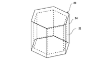
- Each reinforcing material may have a spherical shape, a polyhedral shape, or a pillar shape.
- the main body portion may include a tubular portion as a hollow structure.
- the plurality of reinforcing members may be arranged inside the tubular portion.
- As the fixing portion a plurality of reinforcing materials may be fixed in the tubular portion.
- Each reinforcing material may have a spherical shape.
- the inner diameter of the tubular portion may be 2 times or more and 20 times or less the diameter of the reinforcing material.
- the plurality of reinforcing materials may be arranged in a plurality of layers in the axial direction of the tubular portion.
- the fixing part may contain a filler.
- the filler may be filled in at least a part of the inside of the tubular portion so as to adhere to at least a part of the reinforcing material and the inner surface of the tubular portion among the plurality of reinforcing materials.
- the fixing portion may contain a filler at a plurality of positions separated from each other in the axial direction of the tubular portion.
- a plurality of reinforcing materials may be arranged in a part of the base end portion in the axial direction of the tubular portion.
- the tubular portion may be composed of a plurality of cylinders communicating with each other.
- a plurality of reinforcing members may be arranged in a part of a region of the base end portion of each cylinder.
- the tubular portion may be composed of a plurality of cylinders communicating with each other. Each cylinder may have a flange at at least one end for connecting to an adjacent cylinder. The flanges of adjacent cylinders may be connected to each other. A rib connected between the main surface of the flange portion and the side surface of the tubular portion may be provided. An external reinforcing portion containing a polyurea resin may be provided on the outer surface of the tubular portion so as to cover the pair of connected flange portions and the respective ribs. The external reinforcing portion may be formed of a polyflare resin.
- the fixing part may contain a filler.
- the filler may be filled in at least a part of the inside of the tubular portion so as to adhere to at least a part of the reinforcing material and the inner surface of the tubular portion among the plurality of reinforcing materials.
- the filler may contain a polyurea resin having a higher viscosity than the polyurea resin applied to the outer surface of the tubular portion.
- the structure may be an antenna support pillar that supports the antenna.
- the structure may be a power column that supports the transmission line.
- the structure may be a telephone pole that supports the communication line.
- the structure may be a streetlight pole to which a streetlight can be attached.
- the structure may be a pallet on which articles are placed.
- the structure may be a box having a space inside.
- the structure may be the airframe of a manned or unmanned aircraft.
- the structure may be a vehicle component.
- the structure may be a scaffolding board for construction.
- the structure may be a panel for building materials.
- the structure may further comprise a fastening. One end of the fastening portion may be embedded inside the main body portion. The other end of the fastening may be exposed.
- the structure may be a shock absorber, a corrosion inhibitor, or a heat insulating material.
- the structure may be a pipe body that is inserted as a new pipe into an existing pipe that has deteriorated.
- the structure may be a container used for packing tools.
- the structure may be railroad ties.
- a reinforcing material is provided.
- a plurality of reinforcing materials may be arranged inside the structure to reinforce the structure.
- the stiffener may include a substrate made of resin or metal.
- the reinforcing material may include a base material formed of a fiber reinforced resin.
- the stiffener may further include a coating layer of polyurea resin covering the outer surface of the substrate.
- the reinforcing material may include a base material of a foamed synthetic resin and a coating layer of a polyurea resin. The coating layer may cover the outer surface of the substrate.
- the reinforcing material may be spherical.
- the reinforcing material may be polyhedral or columnar.
- the thickness T1 of the coating layer may be (A / 20) -1 ⁇ T1 ⁇ (A / 20) + 1 [mm], where A is the expansion ratio of the foamed synthetic resin in the base material.
- a method for manufacturing a reinforcing material for reinforcing a structure by arranging a plurality of the inside of the structure may include a molding step of molding the base material of the foamed synthetic resin into a spherical shape, a polyhedral shape, or a pillar shape.
- the base material of the fiber reinforced resin may be molded into a spherical shape, a polyhedral shape, or a column shape.
- An injection step of injecting a coating material of polyurea resin onto the surface of the molded base material may be further provided.
- the base material of the foamed synthetic resin may be molded into a spherical shape, a polyhedral shape, or a pillar shape. Moreover, the size of the base material may be changed.
- the maximum size of the base material of the fiber reinforced resin (diameter when the base material is spherical) may be 10 mm or more.
- the maximum size of the base material may be 1 to 20 times the maximum size of the cross section obtained by cutting the hollow structure of the structure perpendicularly in the axial direction.
- the manufacturing method may further include an injection step of injecting a coating material of polyurea resin onto the surface of the molded base material.
- the thickness of the coating material formed on the surface of the base material at the injection stage may be controlled according to the foaming ratio of the foamed synthetic resin in the base material. Controlled so that the thickness of the coating material (thickness of the coating layer) T1 is (A / 20) -1 ⁇ T1 ⁇ (A / 20) + 1 [mm], where A is the expansion ratio of the foamed synthetic resin in the base material. May be done.
- a method for manufacturing a structure may have a hollow structure that surrounds the interior space.
- the manufacturing method may include a preparation stage, a carry-in stage, and a stage of providing a fixing portion.
- a plurality of reinforcing materials may be prepared.
- the stiffener may include at least a substrate made of resin or metal.
- a base material of a foamed synthetic resin and a coating layer of a polyurea resin may be included.
- the coating layer may cover the outer surface of the substrate.
- a plurality of reinforcing materials may be carried into the internal space through openings provided in the main body.
- a fixing portion for fixing the plurality of reinforcing members in the main body portion may be provided.
- Each reinforcing material may include a base material formed of a fiber reinforced resin.
- Each reinforcing material may include a base material formed of a fiber reinforced resin and a coating layer of a polyurea resin covering the outer surface of the base material.
- Each reinforcing material may include a base material formed of a foamed synthetic resin and a polyurea resin coating layer that covers the outer surface of the base material.
- the manufacturing method may further include a pressing step of pressing a plurality of reinforcing materials into the internal space. After the pressing step, a plurality of reinforcing members may be fixed in the main body by the fixing portion.
- the step of providing the fixing portion may include a filling step of filling at least a part of the internal space with the filler as the fixing portion.
- reinforcing materials of different sizes may be brought into the internal space.
- the plurality of reinforcing materials may be arranged in a plurality of layers inside the main body. Before and after the stage of providing the fixing portion, the carry-in stage may be executed respectively. The interior space may be separated into a plurality of regions by the fixing portion. Before and after the filling step, each carry-in step may be performed. The filler may separate the interior space into multiple regions. The carry-in step and the filling step may be repeated a plurality of times. In each of the plurality of loading stages, the plurality of reinforcing materials may be different in size for each region to be separated. In each of the plurality of loading stages, the plurality of reinforcing materials may have different elasticity of the coating layer for each region to be separated.
- the fixed portion may include a connecting portion whose side surface is connected to the inner surface of the hollow structure and an extending portion extending from the main surface of the connecting portion along the extending direction of the hollow structure.
- a plurality of reinforcing materials may be carried into the space between the stretched portion and the inner surface of the main body portion.
- the filler may contain a polyurea resin.
- Each reinforcing material may be spherical, polyhedral, or columnar.
- the main body portion may include a tubular portion as a hollow structure.
- the plurality of reinforcing members may be arranged inside the tubular portion.
- a plurality of reinforcing materials may be fixed in the tubular portion.
- Each reinforcing material may have a spherical shape.
- the inner diameter of the tubular portion may be 2 times or more and 20 times or less the diameter of the reinforcing material.
- the tubular portion may be composed of a plurality of cylinders communicating with each other. Each cylinder may have a flange at at least one end. The flanges of adjacent cylinders may be connected to each other. A rib connected between the main surface of the flange portion and the side surface of the tubular portion may be provided.
- the manufacturing method may further include an external reinforcing portion forming step of forming an external reinforcing portion on the outer surface of the tubular portion so as to cover the pair of connected flange portions and the respective ribs.
- the external reinforcing portion forming step may further include a coating step of applying the polyurea resin to the outer surface of the tubular portion so as to cover the pair of connected flange portions and the ribs thereof.
- a plurality of reinforcing materials may be arranged in a part of the base end portion in the axial direction of the tubular portion.
- the tubular portion may be composed of a plurality of cylinders communicating with each other.
- a plurality of reinforcing members may be arranged in a part of a region of the base end portion of each cylinder.
- a method for manufacturing a structure including a main body portion may include a preparatory stage and a stage of forming the main body portion.
- a plurality of reinforcing materials may be prepared.
- Each reinforcing material may include a base material made of resin.
- the material of the main body may be molded so that a plurality of reinforcing materials are embedded to form the main body.
- Each reinforcing material may include a base material formed of a fiber reinforced resin.
- Each reinforcing material may include a base material formed of a fiber reinforced resin and a coating layer of a polyurea resin covering the outer surface of the base material.
- Each reinforcing material may include a base material formed of a foamed synthetic resin and a polyurea resin coating layer that covers the outer surface of the base material.
- the material of the main body may be resin or concrete.
- the material of the main body may be a foamed synthetic resin for the main body.
- the step of forming the main body portion may include a step of molding the foamed synthetic resin for the main body portion so that a plurality of reinforcing materials are embedded.
- the manufacturing method may further include a main body coating step of applying the polyurea resin to the outside of the foamed synthetic resin for the main body.
- FIG. 1 It is a side view which shows an example of the antenna support pillar 1. An example of a flange portion and a rib provided at one end of the cylinder 12 is shown. It is an enlarged cross-sectional view of a part of the tubular part 10 in the antenna support pillar 1 of FIG. It is sectional drawing which shows an example of the reinforcing material arranged in the tubular part. It is a figure which shows the relationship between the expansion ratio of the foam synthetic resin which forms a base material 22, and the thickness T1 of a coating layer 24. It is a flowchart which shows an example of the manufacturing process of a reinforcing material. It is sectional drawing which shows the other example of the reinforcing material arranged inside the tubular part.
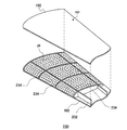
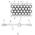
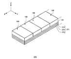
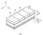
- FIG. 27 It is sectional drawing which shows an example of the cross section of the structure 100 shown in FIG. 27. It is sectional drawing which shows an example of the structure 100 in 10th Embodiment of this invention. It is sectional drawing which shows an example of the structure 100 in 11th Embodiment of this invention. It is sectional drawing which shows an example of the structure 100 in 12th Embodiment of this invention. It is a perspective view which shows an example of the pallet 210 in 13th Embodiment of this invention. It is sectional drawing which shows an example of the cross section of the pallet 210 shown in FIG. 32. It is a perspective view which shows an example of the box body 220 in 14th Embodiment of this invention.
- FIG. 34 It is sectional drawing which shows an example of the cross section of the box body 220 shown in FIG. 34. It is a figure which shows an example of the airframe 230 of the aircraft in 15th Embodiment of this invention. It is a figure which shows an example of the parts of the vehicle in the 16th Embodiment of this invention. It is a figure which shows an example of the scaffolding board for construction in 17th Embodiment of this invention. It is a figure which shows an example of the panel for a building material in 18th Embodiment of this invention. It is a figure which shows an example of the shock absorbing material in the 19th Embodiment of this invention. It is a figure which shows another example of a shock absorber.
- the structure when the structure is a support column, one side in the direction parallel to the height direction of the support column is referred to as "upper” and the other side is referred to as “lower”. Of the two main surfaces of the layer or other member, one surface is referred to as the upper surface and the other surface is referred to as the lower surface.
- the “up” and “down” directions are not limited to the direction of gravity or the mounting direction of the support column.
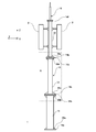
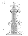
- FIG. 1 is in the first embodiment of the present invention. It is a side view which shows an example of the antenna support pillar 1 for antenna support.
- the antenna support column 1 may be a column or a tower-like structure for installing the antenna 2.
- the antenna support column 1 is an example of a column body which is a structure of the present invention.
- the antenna 2 may be an antenna for various communications such as a mobile phone, a wireless LAN, and a wireless beacon.
- the antenna 2 may be an antenna for a 5th generation mobile communication system (5G).
- the antenna 2 may include both an antenna for a 4th generation mobile communication system (4G) and an antenna for 5G.
- the antenna support column 1 has rigidity that can withstand the weight of the antenna 2.
- the antenna support column 1 of the present embodiment may be a reinforcement of an existing column body.
- the expansion of antenna base stations is approaching its limit, and antennas may be expanded by using the support columns of the existing antenna base stations as they are.
- the weight of the antenna for the 5th generation mobile communication system (5G) is heavier than the weight of the antenna before that. Therefore, when an antenna for 5G is added to the existing column, it is desirable to further increase the rigidity of the antenna support column 1 provided with the antenna for 5G.
- the type of antenna 2 is not limited to these cases.
- the antenna support column 1 of the present embodiment has a plurality of reinforcements including a base material made of metal or resin in a tubular portion constituting the column in order to cope with an increase in weight due to an expansion of the antenna 2. The material is provided.
- the antenna support pillar 1 includes a tubular portion 10 that supports the antenna 2.
- the tubular portion 10 is an example of a main body portion.
- the main body may have a hollow structure that surrounds the internal space.
- the main body portion includes the tubular portion 10 as a hollow structure.
- the tubular portion 10 is configured by communicating a plurality of cylinders 11 (first cylinder), cylinder 12 (second cylinder), and cylinder 13 (third cylinder).
- Each cylinder 11, 12, 13 includes a flange portion 14 at at least one end.
- the cylinder 11 may have a flange portion 14a at one end and a flange portion 14b at the other end.
- the cylinder 12 may have a flange portion 14c at one end and a flange portion 14d at the other end.
- the cylinder 13 may have a flange portion 14e at one end and a flange portion 14f at the other end.
- the flange portions 14b and 14c of the adjacent cylinders 11 and 12 are connected, and the flange portions 14d and 14e of the adjacent cylinders 12 and 13 are connected. In this way, the flange portions 14 of the adjacent cylinders may be connected to each other to form the tubular portion 10.
- the cylinder 11 is arranged at the lowermost position among the plurality of cylinders (direction closer to the base end portion of the tubular portion 10), and the cylinders 12 and 13 are arranged in this order toward the upper side of the cylinder 11 (the tip of the tubular portion 10). May be connected with.
- the inner diameter and outer diameter of the cylinder 11 are the largest among the plurality of cylinders, and the inner diameter and outer diameter may be smaller as the cylinders 12 and 13 are arranged upward in this order.
- Each of the cylinders 11, 12, and 13 may have an inner diameter and an outer diameter constant within a predetermined range from one end to the other end.
- Each cylinder 11, 12, and 13 constituting the tubular portion 10 may be formed of a metal such as a steel material, and may be further subjected to surface treatment such as hot-dip galvanizing.
- the tubular portion 10 may be made of fiber reinforced plastic (FRP).
- the tubular portion 10 as the main body portion may include at least one material selected from the group consisting of metal, ceramic, wood, and resin.
- the flange portion 14a provided at the lower end of the cylinder 11 may be used when the antenna support pillar 1 is attached to a structure such as a building.
- a separate mounting structure may be provided instead of the flange portion 14a.
- a lightning rod 16 may be attached to the flange portion 14 provided at the upper end of the cylinder 13.
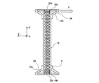
- FIG. 2 shows an example of the flange portion 14 and the rib 15 provided at one end of the cylinder 12.
- Flange portions 14 and ribs 15 in the other cylinders 11 and 13 may have the same configuration.
- a rib 15c extending in the axial direction may be provided between the main surface 18 (upper surface or lower surface) of each flange portion 14 and the side surface 17 of the corresponding cylinder.
- the rib 15c can increase the rigidity of the tubular portion 10.
- a plurality of ribs 15c may be provided per one flange portion 14.
- the plurality of ribs 15c may be provided so as to radiate from the center of the axis in top view. Top view refers to the case of viewing from the positive direction of the Z axis.
- the other flange portion 14 and the rib 15 may have a similar configuration.
- the main surface of the rib 15c may have a triangular shape.
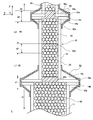
- FIG. 3 is a conceptual diagram showing an enlarged cross section of a part of the tubular portion 10 in the antenna support pillar 1 of FIG.
- FIG. 3 schematically shows a cross section of the A portion of FIG. 1 cut along the ZX plane.
- the antenna support column 1 includes a plurality of reinforcing members 20 arranged inside the tubular portion 10.
- FIG. 3 the arrangement of the plurality of reinforcing members 20 inside the tubular portion 10 is schematically shown.
- the plurality of reinforcing members 20 are arranged inside the main body.
- the main body has a hollow structure surrounding the internal space as in this example, the plurality of reinforcing members 20 are arranged in the internal space.
- a plurality of reinforcing members 20 are arranged in the internal space surrounded by the tubular portion 10.
- the main body of the antenna support column 1 has at least one fixing portion 30 for fixing the plurality of reinforcing members 20 to the inside of the main body.
- the main body has the plurality of reinforcing members 20 inside the tubular portion 10. It is provided with at least one fixing portion 30 for fixing to.
- the fixing portion 30 includes a filler 32.
- the filler 32 is filled in at least a part of the inside of the hollow structure so as to adhere to at least a part of the reinforcing material 20 and the inner surface of the hollow structure among the plurality of reinforcing materials 20.
- the filler 32 is filled in at least a part of the inside of the tubular portion 10 so as to adhere to at least a part of the reinforcing material 20 and the inner surface of the tubular portion 10 among the plurality of reinforcing materials 20. There is.
- a plurality of fillers 32a and 32b are formed.
- the filler 32a adheres to the reinforcing material 20 arranged inside the cylinder 11 and the inner surface of the cylinder 11.
- the filler 32b adheres to the reinforcing material 20 arranged inside the cylinder 12 and the inner surface of the cylinder 12.
- a reinforcing material 20 arranged inside the cylinder 13 and a filler 32 adhering to the inner surface of the cylinder 13 may also be provided.
- the filler 32a may be provided in the range of the thickness d1 in the axial direction of the tubular portion 10.
- the filler 32b may be provided in the range of the thickness d2 in the axial direction of the tubular portion 10. Therefore, in this example, the filler 32 is provided in a part of the inside of the tubular portion 10.
- the filler 32a and the filler 32b may be separated by a length L1.
- the fixing portion 30 may include the filler 32 at a plurality of positions separated from each other in the axial direction of the tubular portion 10.
- the separation distance between the filler 32a and the filler 32b may be smaller than that of L1, and the thicknesses d1 and d2 may be smaller.
- the thickness d1 and the thickness d2 may be the same or different.
- the filler 32a is arranged so as to overlap the portion where the pair of flange portions 14b and 14d are provided in the axial direction of the tubular portion 10.
- the filler 32a is arranged so as to overlap the portion where the pair of flange portions 14d and 14e are provided in the axial direction of the tubular portion 10. Since stress is likely to be applied to the portions where the flange portion 14 and the rib 15 are provided, the rigidity of the tubular portion 10 can be increased by arranging the fillers 32a and 32b in particular.
- the fillers 32a and 32b may be provided at a position different from the connection position between the cylinder 11 and the cylinder 12.
- the filler 32a and the filler 32b separate the internal space of the hollow structure into a plurality of regions.
- the filler 32a and the filler 32b separate the inside of the tubular portion 10 into a plurality of regions.
- the filler 32a and the filler 32b fill a space in the tubular portion 10 so as to surround the reinforcing material 20 in the range of the thickness d1 and the thickness d2, respectively.
- the inside of the tubular portion 10 is separated into a region 41, a region 42, and a region 43 in the axial direction of the tubular portion 10.
- the region 41 is a first region located below the position where the filler 32a is provided.
- the region 42 is a second region sandwiched between the position where the filler 32a is provided and the position where the filler 32b is provided.
- the region 43 is a third region 43 located above the position where the filler 32b is provided.
- the filler 32 may be a resin.
- the filler 32 may be made of a polyurea resin.
- the polyurea resin is, for example, a resin having a urea bond formed by a chemical reaction between isocyanate and an amino group.
- a polyurea resin is formed by reacting a polyisocyanate with a polyamine.
- an external reinforcing portion 52 is provided on the outer surface of the tubular portion 10 so as to cover the pair of flange portions 14b and 14c connected to each other.
- the external reinforcing portion 52 may cover the ribs 15b and 15c together with the flange portions 14b and 14c.
- the external reinforcing portion 52 may cover a part of the side surface of the cylinder 11 and a part of the side surface of the cylinder 12 in the Z-axis direction.
- an external reinforcing portion 54 is provided on the outer surface of the tubular portion so as to cover the pair of connected flange portions 14d and 14e.
- the external reinforcing portion 54 may cover the ribs 15d and 15e together with the flange portions 14d and 14e.
- the external reinforcing portion 54 may cover a part of the side surface of the cylinder 12 and a part of the side surface of the cylinder 13 in the Z-axis direction.
- the external reinforcing portions 52 and 54 may be protective films made of polyurea resin.
- the viscosity of the polyurea resin forming the filler 32 may be higher than the viscosity of the polyurea resin contained in the external reinforcing portions 52 and 54. As a result, the fluidity of the external reinforcing portions 52 and 54 is suppressed, and it becomes easy to form the external reinforcing portions 52 and 54 in a specific region in the tubular portion 10. However, not limited to this case, the viscosity of the polyurea resin forming the filler 32 may be lower than that of the polyurea resin contained in the external reinforcing portions 52 and 54, depending on the application.
- the viscosity of the polyurea resin used as the filler 32 is set to be equal to or less than the viscosity of the polyurea resin contained in the external reinforcing portions 52 and 54.
- the external reinforcing portions 52 and 54 are not limited to the protective film formed of the polyurea resin.
- Each reinforcing material 20 may have a spherical shape.
- the shape of each reinforcing member 20 is not limited to the spherical shape.
- the spherical shape is not limited to the true spherical shape, and includes spherical and ellipsoids indicating surface irregularities or sphericity caused by the production process.
- the plurality of reinforcing members 20 may be arranged in a plurality of layers in the axial direction (Z-axis direction) of the tubular portion 10, and may be arbitrarily filled and arranged to form the layers.
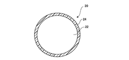
- FIG. 4A is a cross-sectional view showing an example of the reinforcing member 20 arranged inside the tubular portion.
- Each reinforcing material 20 includes a base material 22 and a coating layer 24 that covers the outer surface of the base material 22.
- the base material 22 may have a spherical shape.
- the thickness of the coating layer 24 is smaller than the diameter of the base material 22.
- the diameter of the base material 22 may be 10 mm or more, and the thickness of the coating layer 24 may be 0.5 mm or more and 6 mm or less.
- the base material 22 has a diameter of 40 mm
- the coating layer 24 has a thickness of 4 mm
- the reinforcing material 20 as a whole has a diameter of 48 mm.
- the base material 22 is made of a foamed synthetic resin.
- the synthetic resin forming the base material 22 is a polymer compound.
- the synthetic resin forming the substrate 22 is made of one or more materials selected from polystyrene, polyethylene, polypropylene and polyurethane.
- the foamed synthetic resin refers to a resin in which fine bubbles are dispersed in these synthetic resins.
- the substrate 22 is made of expanded polystyrene (expanded polystyrene).
- the coating layer 24 is provided so as to cover the entire outer surface of the base material 22.
- the coating layer 24 is made of polyurea resin.
- the polyurea resin is, for example, a resin having a urea bond formed by a chemical reaction between isocyanate and an amino group.
- a polyurea resin is formed by reacting a polyisocyanate with a polyamine.
- the greater the content ratio of "diethyltoluenediamine" which is a constituent solution of an amine solution and "diphenylmethane diisocyanate" which is a constituent solution of an isocyanate solution the higher the hardness of the polyurea resin and the lower the elasticity.
- the polyurea resin contained in the filler 32 may have a higher viscosity than the polyurea resin in the coating layer 24. However, this is not the case.
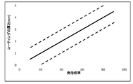
- FIG. 4B is a diagram showing the relationship between the expansion ratio of the foamed synthetic resin forming the base material 22 and the thickness T1 of the coating layer 24.
- the thickness T1 of the coating layer 24 is determined according to the expansion ratio of the base material 22.
- the expansion ratio indicates, for example, the expansion ratio (volume ratio) when synthetic resin particles (raw material beads) are expanded by heating with steam or the like. More specifically, in a 50-fold foam, air accounts for 98% of the entire product (volume), and synthetic resin accounts for 2%.
- the foaming ratio and the strength of the foamed synthetic resin are inversely proportional. For example, a foamed synthetic resin having a foaming ratio of 30 times has twice the strength of a foamed synthetic resin having a foaming ratio of 60 times, but its volume is about half.
- the foaming ratio is selected according to the application of the structure in which the reinforcing material 20 is used.
- the thickness that the base material 22 should have is determined according to the application.
- the foaming ratio is determined according to the strength of the base material 22.
- the thickness T1 of the coating layer 24 is set so as to be substantially proportional to the expansion ratio.
- the thickness T1 of the coating layer 24 is about A / 20 [mm] with the foaming ratio as A.
- the thickness T1 of the coating layer 24 is preferably about 2 mm.
- the thickness T1 of the coating layer 24 is preferably about 3 mm.
- the thickness T1 of the coating layer 24 may be increased or decreased with respect to the standard thickness. As an example, if it is desired to have higher strength, the thickness T1 of the coating layer 24 is increased, and if it is desired to further reduce the cost, the thickness T1 of the coating layer 24 is decreased. As an example, the thickness T1 of the coating layer 24 may be in the following range shown by the dotted line in FIG. 4B. (A / 20) -1 ⁇ T1 ⁇ (A / 20) +1 [mm]
- the foaming ratio of the foamed synthetic resin can be estimated from the material type of the synthetic resin and the weight per unit volume of the foamed synthetic resin. That is, the volume of the synthetic resin before foaming is estimated from the weight per unit volume of the foamed synthetic resin and the material of the synthetic resin. Then, the foaming ratio is calculated from the estimated volume of the synthetic resin before foaming and the unit volume of the foamed synthetic resin.
- FIG. 4C is a flowchart showing an example of the manufacturing process of the reinforcing material 20.
- the application selection step S11 the application (type of structure) of the structure in which the reinforcing material 20 is used is selected.
- the foaming ratio of the foamed synthetic resin used for the reinforcing material 20 is selected.
- the foaming ratio may be determined according to the use of the structure selected in S11.
- the base material of the foamed synthetic resin is molded into a predetermined shape.
- the base material 22 of the foamed synthetic resin is molded into a spherical shape, a polyhedral shape, or a pillar shape.
- each parameter for injecting the coating material is set.
- the parameter includes, for example, the injection amount of the coating material per unit time with respect to the unit area of the base material 22.
- the base material 22 may be heated and pressed in the heating and pressing step S15.
- the heating pressing step S15 may be omitted.
- the coating material is injected onto the base material 22.
- the coating material is dried.
- the coating layer 24 is formed on the surface of the base material.
- FIG. 4D is a cross-sectional view showing another example of the reinforcing member 20 arranged inside the tubular portion.
- the reinforcing material 20 includes a base material 22 formed of a foamed synthetic resin and a polyurea resin coating layer 24 covering the outer surface of the base material 22 has been described. ..
- the present invention is not limited to this case.
- each reinforcing material 20 includes a base material 23.
- the base material 23 is made of fiber reinforced plastic (FRP).
- the base material 23 may be made of a glass fiber reinforced resin (GFRP) or a carbon fiber reinforced resin (CFRP).
- Glass fiber reinforced resin (GFPR) is made by hardening glass fiber with polyester resin, vinyl ester resin, epoxy resin, phenol resin, or other thermoplastic resin.
- Carbon fiber reinforced resin (CFRP) is obtained by solidifying carbon fiber (carbon fiber) with polyester resin, vinyl ester resin, epoxy resin, phenol resin, or other thermoplastic resin.
- the fiber reinforced plastic (FRP) is not limited to the glass fiber reinforced resin (GFRP) and the carbon fiber reinforced resin (CFRP).
- the fiber reinforced plastic may be an aramid fiber (Kevlar fiber) reinforced resin, a polyethylene fiber (Dyneema fiber) reinforced resin, a Zylon fiber reinforced resin, or a boron fiber reinforced resin.
- Each reinforcing material 20 may include a polyurea resin coating layer 24 that covers the outer surface of the base material 23. However, the reinforcing material 20 does not necessarily include the coating layer 24.
- FIG. 4E is a cross-sectional view showing another example of the reinforcing material arranged inside the tubular portion.
- the reinforcing material 20 contains a base material 23 made of a fiber reinforced resin (FRP), but does not include a coating layer 24 of a polyurea resin.
- a base material made of metal can be used instead of the base material 23 made of fiber reinforced plastic (FRP).
- FRP fiber reinforced plastic
- the base material 23 uses the reinforcing material 20 in which the base material 23 is made of glass fiber reinforced resin (GFRP) or carbon fiber reinforced resin (CFRP)
- the base material 22 is made of foamed synthetic resin.
- the rigidity of the structure can be increased as compared with the case of the embodiment (FIG. 4A) in which the reinforcing member 20 is used.
- the reinforcing material 20 in which the base material 23 is formed of glass fiber reinforced resin (GFRP) or carbon fiber reinforced resin (CFRP). It is desirable to use.
- the material of the base material can be selected depending on the application.
- the base material 23 of the fiber reinforced plastic (FRP) is molded into a predetermined shape.
- the base material 22 of the fiber reinforced plastic (FRP) is molded into a spherical shape, a polyhedral shape, or a pillar shape.
- each parameter for injecting the coating material is set.
- the injection step S16 the coating material is injected onto the base material 23. In S16, it is preferable to spray the coating material on the entire surface of each base material 23.
- the coating material is dried.
- the coating layer 24 is formed on the surface of the base material.
- S14, S16, and S17 are further omitted. Since the other steps are the same as the manufacturing steps of the reinforcing material 20 shown in FIG. 4D, the repeated description will be omitted.
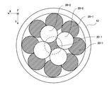
- FIG. 5 is a plan view showing an example of arrangement of the reinforcing material in the cylinder 12.
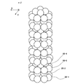
- the plurality of reinforcing members 20 are arranged in a plurality of layers in the axial direction of the tubular portion 10.
- the inner diameter of the cylinder 12 is 180 mm
- the diameter of the reinforcing member 20 is 48 mm.
- the plurality of reinforcing materials 20-1 form the first layer
- the plurality of reinforcing materials 20-2 form the second layer.
- a total of nine reinforcing members 20-1 constitute the first layer.
- the first layer has ten pieces arranged so that the vertices of the respective reinforcing members 20-1 coincide with the vertices of a substantially regular octagon while contacting the inner surface of the cylinder 12. It includes a reinforcing material 20-1 and one reinforcing material 20-1 placed in the center of the cylinder 12.
- the second layer contains two reinforcing members 20-2 arranged so that the vertices of the respective reinforcing members 20-2 coincide with the vertices of a substantially regular quadrangle in a top view.
- FIG. 6 is a diagram showing an example of the layer structure of the reinforcing material in the cylinder 12.
- the third layer composed of the plurality of reinforcing members 20-3 may have the same arrangement as the first layer.
- the fourth layer composed of the plurality of reinforcing members 20-4 has a configuration in which the arrangement in the second layer is rotated by 45 degrees on a plane parallel to the XY plane. From the fifth layer onward, the configurations of the first layer to the fourth layer are repeated.
- FIG. 7 is a plan view showing an example of arrangement of the reinforcing material in the cylinder 11.
- the plurality of reinforcing members 20 may be arranged in a plurality of layers inside the main body portion.
- the plurality of reinforcing members 20 are arranged in a plurality of layers in the axial direction of the tubular portion 10.
- the inner diameter of the cylinder 11 is 204.5 mm
- the diameter of the reinforcing member 20 is 48 mm.
- the plurality of reinforcing materials 20-1 form the first layer
- the plurality of reinforcing materials 20-2 form the second layer.
- a total of 11 reinforcing members 20-1 constitute the first layer.
- the first layer has ten pieces arranged so that the vertices of the respective reinforcing members 20-1 coincide with the vertices of a substantially regular decagon while contacting the inner surface of the cylinder 11. It includes a reinforcing material 20-1 and one reinforcing material 20-1 placed in the center of the cylinder 11.
- the second layer contains five reinforcing members 20-2 arranged so that the vertices of the respective reinforcing members 20-2 coincide with the vertices of a substantially regular polygon in top view.
- each layer may have a configuration in which the reinforcing member 20 is arranged at the apex of a substantially regular decagon while contacting the inner surface of the cylinder 11 in top view.
- the third layer and the fourth and subsequent layers may be the same as the first layer and the second layer.
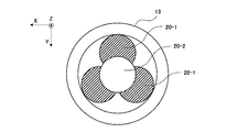
- FIG. 8 is a plan view showing an example of arrangement of the reinforcing material in the cylinder 13.
- the inner diameter of the cylinder 13 is 106 mm
- the diameter of the reinforcing member 20 is 48 mm.
- the first layer has three reinforcements arranged so that the vertices of the respective reinforcing members 20-1 coincide with the vertices of a substantially equilateral triangle while contacting the inner surface of the cylinder 13 in top view. Includes material 20-1.
- the second layer contains one reinforcing material 20-2 placed in the center of the cylinder 13 in top view.
- the diameter (48 mm) of the reinforcing material 20 is 33% of the inner diameter (180 mm) of the cylinder 12, and is 20% or more and 40% or less. Included in the range.
- the diameter (48 mm) of the reinforcing material 20 is 23% of the inner diameter 204.5 mm of the cylinder 12, and is included in the range of 20% or more and 30% or less. It has been.
- the diameter (48 mm) of the reinforcing material 20 is 45% of the inner diameter (106 mm) of the cylinder 13, and covers the range of 20% or more and 50% or less. It is rare.
- the inner diameter (180 mm) of the cylinder 12 is 3.75 times the diameter of the reinforcing material 20, and the inner diameter (204.5 mm) of the cylinder 11 is 4.26 times the diameter of the reinforcing material 20.
- the inner diameter (106 mm) of the cylinder 13 is 2.2 times the diameter of the reinforcing material 20.
- the inner diameter of the tubular portion 10 is preferably 1 time or more and 20 times or less the diameter of the reinforcing material 20, more preferably 1 time or more and 10 times or less the diameter of the reinforcing material 20, or 2 times or more and 10 times or less.
- the arrangement of the reinforcing member 20 in the tubular portion 10 is not limited to the cases of FIGS. 5, 6, 7, and 8.
- the reinforcing member 20 does not necessarily have to be arranged in layers in the tubular portion 10.
- a plurality of reinforcing members 20 are provided in the internal space from an opening provided in the main body portion of the tubular portion 10.
- the plurality of reinforcing members 20 are not necessarily arranged in layers. Even when the plurality of reinforcing members 20 are randomly arranged instead of being arranged in layers, the inner diameter of the tubular portion 10 is 1 to 20 times the diameter of the reinforcing material 20, more preferably the diameter of the reinforcing material 20.
- the diameter of the reinforcing material 20 is preferably 10 mm or more.
- the diameters of the reinforcing material 20 to be put into the cylinder having an inner diameter of 300 mm were 10 mm, 20 mm, 40 mm, and 60 mm, the rigidity of the structure could be maximized when the diameter of the reinforcing material 20 was 60 mm.
- the size of the reinforcing material 20 is increased, it is possible to prevent the reinforcing material 20 from moving to the space created when the structure such as a cylinder is bent by receiving an external force, and the rigidity can be increased. it can.
- the reinforcing member 20 is arranged in the tubular portion 10.
- the reinforcing member 20 can increase the rigidity in the tubular portion 10 and suppress the displacement. Therefore, the stress generated in the antenna support column 1 can be suppressed.
- the inner diameter of the tubular portion 10 is twice or more and 20 times or less, particularly twice or more and 10 times or less the diameter of the reinforcing member 20, the stress generated in the antenna support column 1 can be suppressed.
- the rigidity in the tubular portion 10 can be increased by using the reinforcing material 20 in which the base material 23 is formed of the transition reinforcing resin.
- the reinforcing material 20 including the base material 22 made of the foamed synthetic resin can be used, and the weight of the antenna support column 1 can be reduced.
- external reinforcing portions 52 and 54 are provided on the outer surface of the tubular portion 10 so as to cover the pair of flange portions 14 and the ribs 15 connected to each other. As a result, the portion where local stress is likely to be generated can be covered from the outside, so that the generated stress can be reduced.
- the filler may be contained at a plurality of positions separated from each other in the axial direction of the tubular portion 10.
- a filler having a faster curing rate can be used as compared with the case where the entire inside of the tubular portion 10 is filled with the filler.
- the structure of this example includes the tubular portion 10 as a hollow structure, it exhibits flexibility as compared with a solid structure having the same cross-sectional area, and produces several times the strength. Further, in the present embodiment, since the filler 32 made of a strong polyurea resin is included at a plurality of positions separated from each other in the axial direction of the tubular portion 10, the filler 32 serves as a horizontal member and is bent. The strength of the whole bamboo against stress can be increased. It has the same effect as the bamboo node structure of plants.
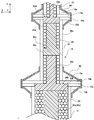
- FIG. 9 is a partial cross-sectional view showing an example of an antenna support column in the second embodiment of the present invention.
- a plurality of fillers 32b and 32c may be provided inside one cylinder 12.
- three or more fillers 32a, 32b, and 32c are provided as the entire tubular portion 10.
- FIG. 10 is a partial cross-sectional view showing an example of an antenna support column according to the third embodiment of the present invention.
- the plurality of reinforcing members 20 may include reinforcing members 20a, 20b, and 20c having different sizes from each other.
- the sizes of the plurality of reinforcing members 20a, 20b, and 20c to be arranged may be different for each region separated by the fixing portion 30 (filling material 32a and filling material 32b in this example).
- the sizes of the plurality of reinforcing members 20a, 20b, and 20c arranged in the region 41, the region 42, and the region 43 are different.
- the sizes of the reinforcing members 20a, 20b, and 20c can be changed according to the inner diameter of the cylinder. Therefore, it becomes easy to arrange the reinforcing member 20a densely in the cylinder. As a result, the strength of the antenna support column 1 can be increased.
- each of the coating layers 24 of the plurality of reinforcing materials 20a, 20b, and 20c to be arranged may be different for each region separated by the filler 32a and the filler 32b.
- the reinforcing material 20a may be more rigid (lower elastic) than the reinforcing material 20b, may be more rigid than the reinforcing material 20c (lower elastic) than the reinforcing material 20b, and vice versa.
- FIG. 11 is a partial cross-sectional view showing an example of an antenna support column in the fourth embodiment of the present invention.
- the plurality of reinforcing members 20 may include reinforcing members 20 and 21 having different sizes from each other.
- the reinforcing material 20 and the reinforcing material 21 may be mixed in the region in the tubular portion 10. As shown in FIG. 11, the reinforcing members 20 are not necessarily arranged in layers, and may be arranged randomly.
- the reinforcing material 20 and the reinforcing material 21 having different diameters are mixed in the tubular portion 10, so that the filling rate of the reinforcing material 20 in the tubular portion 10 can be increased. Therefore, it becomes easy to arrange the reinforcing member 20a densely in the cylinder. As a result, the strength of the antenna support column 1 can be increased.
- FIG. 12 is a partial cross-sectional view showing an example of a pillar body for supporting an antenna in the fifth embodiment of the present invention.
- a filler 32 filled over the entire inside of the tubular portion 10 may be used as the fixing portion 30, a filler 32 filled over the entire inside of the tubular portion 10 may be used.
- a filler 32 having a slower curing rate than the polyurea resin may be used.
- FIG. 13 is a diagram showing an example of a method for manufacturing the structure of the present invention.
- a method of manufacturing an antenna support column is shown as an example of the structure.
- the structure includes a main body portion that is a hollow structure surrounding the internal space.
- the method for manufacturing the structure includes a preparatory step (step S101).
- a plurality of reinforcing members 20 are prepared.
- the reinforcing material 20 may include a base material 22 made of a foamed synthetic resin and a coating layer 24 made of a polyurea resin that covers the outer surface of the base material 22.
- the reinforcing material 20 may include a base material 22 made of a foamed synthetic resin and a coating layer 24 made of a polyurea resin that covers the outer surface of the base material 22.
- the reinforcing material 20 may include the base material 23 of the fiber reinforced resin and the coating layer 24 of the polyurea resin that covers the outer surface of the base material 23, and is shown in FIG. 4E. As described above, the base material 23 of the fiber reinforced resin is provided, and the coating layer 24 may not be provided.
- the manufacturing method includes a carry-in stage in which a plurality of reinforcing materials 20 are carried into the internal space through openings provided in the main body (step S102).
- a carry-in stage in which a plurality of reinforcing materials 20 are carried into the internal space through openings provided in the main body (step S102).
- the portion of the lightning rod 16 is removed, and one end (upper end) of the tubular portion 10 in which the cylinder 13, the cylinder 12, and the cylinder 11 are communicated is exposed.
- an opening is provided at one end of the tubular portion 10, and the portion of the lightning rod 16 functions as a cover portion that closes the opening.
- the manufacturing method includes a step of providing a fixing portion 30 for fixing the plurality of reinforcing members 20 in the main body portion.
- the step of providing the fixing portion 30 includes a filling step of filling at least a part of the inside of the tubular portion with the filler 32 for fixing the plurality of reinforcing members 20 in the tubular portion 10.
- the filler 32 is filled so as to adhere to at least a part of the reinforcing members 20 and the inner surface of the tubular portion 10.
- the filler 32 may be a polyurea resin.
- the carrying-in of the reinforcing material 20 is suspended. Then, the filler 32a is filled through the nozzle 64 or the like inserted into the tubular portion 10. Since the reinforcing member 20 is provided in the tubular portion 10, the process can be completed in a shorter period of time as compared with the case where the space in the tubular portion 10 is filled only with the filler 32a. Further, unlike the case where the space in the tubular portion 10 is filled only with the filler 32a, a polyurea resin having a relatively short curing time can be used as the filler 32a, and the rigidity of the antenna support column 1 can be increased. ..
- the carry-in step (step S102) and the filling step (step S103) are repeatedly executed a plurality of times.
- the carry-in step (step S102) is executed before and after the step of providing the fixing portion.
- the carry-in step (step S102) is executed before and after the filling step (step S103).
- the internal space of the main body is separated into a plurality of regions.
- the fillers 32a and 32b are arranged at a plurality of positions separated from each other in the axial direction of the tubular portion 10.
- the insertion device inserted into the tubular portion 10 may alternately supply the reinforcing material 20 and the filler 32 at predetermined time intervals.
- the size of the plurality of reinforcing members 20 to be arranged may be different for each separated region.
- the elasticity of the coating layer 24 of the plurality of reinforcing members 20 to be arranged may be different for each separated region.
- reinforcing members 20 having different sizes may be carried into the tubular portion 10.
- the plurality of reinforcing members 20 may be arranged in a plurality of layers inside the main body portion, or may be arbitrarily filled and arranged to form the layers.
- the plurality of reinforcing members 20 may be arranged in a plurality of layers in the axial direction of the tubular portion 10.
- the manufacturing method may include a coating step (step S104).
- the tubular portion 10 includes a cylinder 11, a cylinder 12, and a cylinder 13.
- Each cylinder has a flange portion 14 for connecting to an adjacent cylinder.
- Flange portions 14 of adjacent cylinders are connected to each other to form a tubular portion 10. Therefore, in the coating step (step S104), the polyurea resin is applied to the outer surface of the tubular portion 10 so as to cover the pair of connected flange portions.
- the outer reinforcing portions 52 and 54 containing the polyurea resin are formed on the outer surface of the tubular portion 10.
- the external reinforcing portions 52 and 54 containing the polyurea resin may be formed through the nosol 66a and the nosol 66b arranged on the side surface of the tubular portion 10.
- the antenna support column 1 having enhanced rigidity can be manufactured by using the tubular portion 10 already existing in the base station or the like. So to speak, the manufacturing method of the present embodiment can also be used as a method of reinforcing the existing antenna support column 1. Of course, the manufacturing method of the present embodiment can be utilized as a completely new manufacturing method of the antenna support column 1 without using the existing tubular portion 10.
- the manufacturing method is not limited to the case shown in FIG. 13, and various changes can be made.
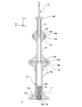
- FIG. 14 is a diagram showing an example of a carry-in device.
- the carry-in device 90 includes a storage tank 91, a supply pipe 92, a motor 93, an aligned supply device 94, a transfer pipe 95, a blower 96, and a control unit 97.
- the reinforcing material 20 housed in the storage tank 91 is supplied to the transport pipe 95 having an inner diameter slightly larger than that of the reinforcing material 20 by the aligned supply device 94 driven by the motor 93 through the supply pipe 92.
- the compressed air discharged from the blower 96 flows into the transport pipe 95 and conveys the reinforcing material 20 in the transport pipe 95.
- a plurality of reinforcing members 20 may be carried into the internal space of the main body by using such a carry-in device 90.
- the control unit 97 controls the blower 96 and the motor 93. According to such a carry-in device 90, the number of carry-in reinforcing materials 20 within a unit time can be increased. Further, since the reinforcing material 20 is sent out into the internal space by applying pressure to the transport pipe 95, it becomes easy to arrange a plurality of reinforcing materials 20 in the internal space.
- the method for manufacturing a structure of the present invention further includes a pressing step of pressing the plurality of reinforcing members 20 into the internal space, and after the pressing step, the plurality of reinforcing members 20 are placed in the main body by the fixing portion 30. It may be fixed.
- the means for pressing the plurality of reinforcing members 20 into the internal space is not limited to compressed air. You may press it with a stick for pressing.
- the filling density of the reinforcing members 20 increases and the position is fixed by pressing. As a result, the effect of increasing the strength of the structure is increased.
- the filler 32 has been mainly described as the fixing portion 30 for fixing the plurality of reinforcing members 20 to the inside of the main body portion.
- the fixing portion 30 is not limited to such a filler 32.
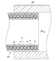
- FIG. 15 is a partial cross-sectional view showing an example of an antenna support column in the sixth embodiment of the present invention.
- the overall structure of the sixth embodiment is similar to that of the first embodiment shown in FIGS. 1 to 8.
- FIG. 15 schematically shows a cross section of the A portion of FIG. 1 cut along the ZX plane.
- the main body portion of the antenna support column 1 has at least one fixing portion 30 for fixing the plurality of reinforcing members 20 inside the main body portion, and the fixing portion 30 fixes the plurality of reinforcing members 20 in the tubular portion 10. ..
- the fixing portion 30 includes a connecting portion 33 and an extending portion 34.
- the fixing portion 30 may be made of metal or resin.
- As the resin for example, glass fiber reinforced resin (GFRP) or carbon fiber reinforced resin (CFRP) is used.
- the connecting portion 33 and the extending portion 34 may be integrally formed.
- the side surface of the connecting portion 33 is connected to the inner surface of the hollow structure.
- the connecting portion 33 may have a plate shape.
- the connecting portion 33 includes two main surfaces and a side surface connecting the two main surfaces.
- the side surface of the plate-shaped connecting portion 33 may be connected to the inner surface of the hollow structure.
- the connecting portion 33 is connected to the inner surface of the tubular portion 10.
- the connecting portion 33 may be connected to the inner surface of the hollow structure by being press-fitted into the hollow structure, or may be connected to the inner surface of the hollow structure by adhesive, welding, or the like.
- the shape of the connecting portion 33 may correspond to the shape of the internal space of the hollow structure.
- the shape of the connecting portion 33 may be a disk shape facing the inner diameter shape of the tubular portion 10.
- the connecting portion 33 may separate the internal space into a plurality of regions. In this example, the inside of the tubular portion 10 is separated into a plurality of regions.
- the stretched portion 34 may be stretched from the main surface of the connecting portion 33 along the stretching direction of the hollow structure.
- the stretched portion 34 may be stretched along the axial direction of the tubular portion 10.
- the extending portion 34 may be extended from the vicinity of the center of one main surface of the connecting portion 33.
- the diameter of the stretched portion 34 may be 10% or more and 80% or less of the inner diameter of the tubular portion 10.
- the inside of the tubular portion 10 may be separated into a region 41, a region 42, and a region 43 in the axial direction of the tubular portion 10.
- Three cylinders 11, 12, and 13 are connected to the tubular portion 10.
- One fixing portion 30 may be provided in one cylinder. Taking the region 42 as an example, the extension portion 34b of the fixing portion 30b is provided inside the cylinder 12. Then, the end portion of the stretched portion 34b comes into contact with the main surface (front surface or back surface) of the connecting portion 33c of the other adjacent fixing portions 30c in the vicinity of the connecting region between the cylinder 12 and the cylinder 13.
- the plurality of reinforcing members 20 may be arranged in the space between the stretched portion 34b and the inner surface of the hollow structure.
- the plurality of reinforcing members 20 are arranged in the space between the stretched portion 34b and the inner surface of the tubular portion 10. Then, the positions of the plurality of reinforcing members 20 are fixed by the connecting portion 33b, the connecting portion 33c, the extension portion 34b, and the inner surface of the tubular portion 10 (hollow structure).
- the stretched portion 34 since the stretched portion 34 is provided, the number of a plurality of reinforcing members 20 that must be arranged in the internal space can be reduced.
- the rigidity of the tubular portion 10 can be increased while reducing the number of the plurality of reinforcing members 20 arranged inside the tubular portion 10.
- FIG. 16 is a partial cross-sectional view showing an example of a pillar for an antenna according to a seventh embodiment of the present invention.
- a plurality of fixing portions 30b and 30c may be provided inside one cylinder 12.
- the fixing portion 30b is arranged at a position closer to the vicinity of the connection region between the cylinder 12 and the cylinder 11 than the fixing portion 30c.
- the fixing portion 30c is arranged at a position closer to the vicinity of the connection region between the cylinder 12 and the cylinder 13 than the fixing portion 30b.
- the fixing portion 30b includes a connecting portion 33b arranged near the connecting region between the cylinder 12 and the cylinder 11, and an extending portion 34b extending from the connecting portion 33b.
- the fixing portion 30c includes a connecting portion 33c provided near the central portion in the longitudinal direction of the cylinder 12, and an extending portion 34c extending from the connecting portion 33c. Also in this embodiment, the rigidity of the tubular portion 10 can be increased while reducing the number of the plurality of reinforcing members 20 arranged inside the tubular portion 10.
- the fixing portion 30 included the connecting portion 33 and the extending portion 34, but the fixing portion 30 has the connecting portion 33 and has the extending portion 34. You don't have to.
- the connecting portion 33 may be a metal plate that covers the ends of the cylinder 11, the cylinder 12, and the cylinder 13.
- FIG. 17 is a cross-sectional view showing an example of the antenna support column 1 in the eighth embodiment of the present invention.
- an opening is provided in a part of the tubular portion 10.
- an opening is provided at the tip of the tubular portion 10.
- the main body of the tubular portion 10 has a cover portion 55 that closes the opening.
- the cover portion 55 is connected to the flange portion 14f.
- the cover portion 55 functions as the fixing portion 30.
- the cover portion 55 is, for example, a metal plate.
- a lightning rod 16 or the like may be attached to the cover portion 55.
- the filler 32 may not be used as the fixing portion 30.
- the configurations of the external reinforcing portions 51, 52, 54 and the like are the same as in the case of the first embodiment shown in FIG.
- the cover portion 55 functions as the fixing portion 30 the construction becomes easy when the antenna support column 1 and the like are manufactured using the existing pipe.
- the reinforcing material 20 is mainly spherical has been described.
- the shape of the reinforcing material 20 is not limited to the spherical shape.
- FIG. 18 is a diagram showing another example of the reinforcing material.
- the reinforcing material 20 may have a polyhedral shape. In the example shown in FIG. 18, it has a regular tetrahedron, but the reinforcing material 20 is not limited to the regular tetrahedron shape.
- the reinforcing material 20 shown in FIG. 18 may also include a base material 22 and a coating layer 24 that covers the outer surface of the base material 22.
- the base material 22 may have a polyhedral shape corresponding to the shape of the reinforcing member 20.
- FIG. 19 is a diagram showing another example of the reinforcing material.
- the reinforcing member 20 may have a column shape. In the example shown in FIG. 18, it has a regular hexagonal prism shape. Regular hexagonal prisms with a regular hexagonal bottom surface can be arranged closest in the plane.
- the reinforcing material 20 is not limited to the regular hexagonal column shape, and may be another polygonal column or a cylinder.
- the reinforcing material 20 shown in FIG. 18 may also include a base material 22 and a coating layer 24 that covers the outer surface of the base material 22.
- the base material 22 may have a pillar shape corresponding to the shape of the reinforcing member 20.
- the reinforcing material 20 By arranging the reinforcing material 20 other than the spherical shape as shown in FIG. 18 or 19 in the hollow structure, a virtual frame structure caused by the coating layer 24 covering the outer surface of the reinforcing material 20 is formed in the hollow structure. It is composed. Therefore, according to the reinforcing material 20, the strength of the hollow structure can be increased from the inside.
- the maximum size of the shape may be 1 to 20 times the maximum size of the cross section cut perpendicular to the axial direction of the hollow structure. It may be 1 time or more and 10 times or less.
- the maximum size of the shape may be 10 mm or more.
- the base material formed of the fiber reinforced resin (FRP) is replaced with the base material 22 formed of the foamed synthetic resin. 23 may be adopted.
- the coating layer 24 covering the outer surface of the base material 23 may be omitted.
- FIG. 20 is a diagram showing the conditions of the simulation test.
- a cylinder having an outer diameter of 190.7 mm, an inner diameter of 180.1 mm, and a length of 2.3 m was used.
- a plurality of spherical reinforcing members 20 were arranged so as to form the layered structure shown in FIGS. 5 and 6.
- a filler 32a and a filler 32b were provided as fixing portions 30 in the vicinity of one end and the other end of the cylinder 12, and the positions of the spherical reinforcing member 20 were fixed.
- the thickness of the filler 32a and the filler 32b in the axial direction (Z-axis direction) was about 30 mm.
- a spherical reinforcing material 20 having a diameter of 48 mm was used. Specifically, the reinforcing material 20 having a diameter of the base material 22 of 40 mm and a film thickness of the polyurea resin coating layer of 4 mm was used.
- An external reinforcing portion 52 is provided to cover the flange portion 14c and the rib 15c at one end of the cylinder 12. The external reinforcing portion 52 has a film thickness of 4 mm, and a part of the external reinforcing portion 52 is stretched along the side surface of the cylinder 12.
- an external reinforcing portion 54 is provided to cover the flange portion 14d and the rib 15d at the other end of the cylinder 12. The external reinforcing portion 54 has a film thickness of 4 mm, and a part of the external reinforcing portion 54 is stretched along the side surface of the cylinder 12.
- the height h of the antenna support column is 2.3 m
- the outer diameter D 1 of the support column is 190.7 mm
- the inner diameter D 2 is 180.1 mm.
- Z is a section modulus
- Z I (moment of inertia) / e (distance of the center of gravity)
- e 14.4 (mm)
- the inner diameter is reduced equivalently by providing the reinforcing material 20, the filler 32a, the filler 32b, the external reinforcing portion 52, and the external reinforcing portion 54.
- the rigidity of the tubular portion 10 can be increased and the displacement of the tubular portion 10 is suppressed, so that it occurs at the P point.
- the stress to be applied was suppressed.
- the external reinforcing portions 52 and 54 the stress generated is suppressed by coating the portion where the stress tends to increase from the outside.
- a three-point bending test was performed using a cylinder having an outer diameter of 190.7 mm, an inner diameter of 180.1 mm, a wall thickness of 5.3 mm, and a length of 800 mm.
- the two receiving round bars were separated from each other at a distance of 600 mm from the center, and the sample was placed on the center. Then, the midpoint between the centers of the two receiving round bars was pressed with the round bar, and the breaking load was measured.
- the receiving round bar and the push round bar had a diameter of 50 mm.
- the reinforcing material 20 is not arranged by arranging the base material 22 formed of the foamed synthetic resin, the coating layer 24 covering the outer surface of the base material 22, and the reinforcing material 20 having a diameter of 40 mm in the internal space of the cylinder.
- the breaking load (N) was increased by about 15%.
- the breaking load (N) is higher than that in the case where the reinforcing material 20 is not arranged. , About 20% higher.
- the internal space of the cylinder is composed of a base material 22 made of foamed synthetic resin, a coating layer 24 covering the outer surface of the base material 22, and a reinforcing material 20 having a diameter of 40 mm.
- the amount of displacement could be reduced by 23.8% as compared with the case of arranging in.
- the reinforcing material 20 of the glass fiber reinforced resin (GFRP) or the carbon fiber reinforced resin (CFRP) is arranged and fixed in the cylinder, and the reinforcing material 20 and the outside are provided by providing the external reinforcing portion 52.
- Rigidity could be improved by 17.8% as compared with the case where the reinforcing portion 52 was not arranged.
- the stress applied to the proximal end portion could be reduced by about 65%. It should be noted that the effect of improving the rigidity and reducing the stress was confirmed to be the same in the actual antenna support column in which the three cylinders 11, 12, and 13 were connected to form the tubular portion 10.
- the configuration of the tubular portion 10 is not limited to the case shown in FIG.
- the reinforcing material 20 or the fillers 32a and 32b are provided in the internal space of the tubular portion 10 in the region extending from the base end portion to the tip end portion of the tubular portion 10.
- the reinforcing material 20 is provided in the internal space of the tubular portion 10. Was shown when was placed.
- the present invention is not limited to this case.
- FIG. 21 is a diagram showing a modified example of the antenna support column 1.
- a plurality of reinforcing members 20 are arranged in a part of a base end portion (end portion on the ⁇ Z side) in the axial direction (Z-axis direction) of the tubular portion 10.
- the reinforcing member 20 is not arranged in the internal space of the tubular portion 10 except for a part of the base end portion.
- the maximum stress is applied to the rib 15a provided at the base end portion (lower end portion) of the tubular portion 10. Therefore, a part of the base end portion is provided so as to correspond to the portion to which the maximum stress is applied in the axial direction (Z-axis direction) of the tubular portion 10.
- a part of the region of the proximal end portion may be in the range of L / 3 from the end of the proximal end portion of the tubular portion 10, and is in the range of L / 5. You may.
- the tubular portion 10 includes a plurality of cylinders 11, a cylinder 12, and a cylinder 13.
- the cylinder 11 is arranged at a position closest to the base end portion of the tubular portion 10 among the plurality of cylinders
- the cylinder 13 is arranged at a position closest to the tip end portion of the tubular portion 10 among the plurality of cylinders.
- the cylinder 12 is arranged between the cylinder 11 and the cylinder 13.
- the reinforcing material 20 is arranged in the internal space of the cylinder 11 arranged at the position closest to the base end portion of the tubular portion 10 among the plurality of cylinders.
- the fixing portion 30 includes fillers 32a and 32b.
- the fillers 32a and 32b are filled in at least a part of the inside of the hollow structure so as to adhere to at least a part of the reinforcing material 20 and the inner surface of the hollow structure among the plurality of reinforcing materials 20.
- a plurality of fillers 32a and 32b are formed as the filler 32.
- the filler 32a is provided at a position closer to the base end portion than the filler 32b.
- the positions of the plurality of reinforcing materials 20 may be fixed so that the plurality of reinforcing materials 20 are sandwiched between the filler 32a and the filler 32b.
- a plurality of reinforcing members 20 are arranged in the internal space of the tubular portion 10 in the region of the base end portion. Therefore, the rigidity of the tubular portion 10 can be effectively increased. Further, since the plurality of reinforcing materials 20 are centrally arranged in a part of the base end portion, the amount of the plurality of reinforcing materials 20 used can be reduced, and the plurality of reinforcing materials 20 can be placed in the tubular portion 10. It is possible to shorten the carry-in stage of carrying in.
- FIG. 22 is a diagram showing a modified example of the pillar body for supporting the antenna.
- the tubular portion 10 includes a plurality of cylinders 11, a cylinder 12, and a cylinder 13.
- a plurality of reinforcing members 20 are arranged in a part of each base end portion of the cylinder 11, the cylinder 12, and the cylinder 13.
- a plurality of reinforcing members 20 are arranged in a part of a region of the base end portion (end portion on the ⁇ Z side) of the tubular portion 11.
- the reinforcing member 20 is not arranged in the internal space of the cylinder 11 except for a part of the base end portion. Similarly, a plurality of reinforcing members 20 are arranged in a part of the base end portion (end portion on the ⁇ Z side) of the cylinder 12. A plurality of reinforcing members 20 are arranged in a part of a region of the base end portion of the cylinder 13. Assuming that the length of the cylinder 11 is L, a part of the region of the base end portion may be in the range of L / 3 from the end of the base end portion of the cylinder 11, or may be in the range of L / 5. A part of the base end portion of the cylinder 12 and the cylinder 13 may be the same as in the case of the cylinder 11.
- the fixing portion 30 includes fillers 32a and 32b.
- the fillers 32a and 32b are filled in at least a part of the inside of the hollow structure so as to adhere to at least a part of the reinforcing material 20 and the inner surface of the hollow structure among the plurality of reinforcing materials 20.
- the filler 32a is provided in the cylinder 11 at a position closer to the base end portion of the cylinder 11 than the filler 32b.
- the plurality of reinforcing materials 20 may be fixed in the cylinder 11 so that the plurality of reinforcing materials 20 are sandwiched between the filler 32a and the filler 32b.
- the filler 32c is provided at a position closer to the base end portion of the cylinder 12 than the filler 32d.
- the plurality of reinforcing materials 20 may be fixed in the cylinder 12 so that the plurality of reinforcing materials 20 are sandwiched between the filler 32c and the filler 32d.
- the filler 32e is provided at a position closer to the base end portion of the cylinder 13 than the filler 32f.
- the plurality of reinforcing materials 20 may be fixed in the cylinder 13 so as to sandwich the plurality of reinforcing materials 20 between the filler 32e and the filler 32f.
- FIG. 23 is a diagram showing a modified example of the pillar body for supporting the antenna.
- the case where the cylinder 11, the cylinder 12, and the cylinder 13 having different diameters are communicated with each other to provide the tubular portion 10 is shown.
- the present invention can also be applied to an antenna support column 1 having a tubular portion 10 including one cylinder instead of a plurality of cylinders as shown in FIG. 24.
- FIG. 24 is a diagram showing a modified example of the pillar body for supporting the antenna.
- the case where the inner diameter and the outer diameter of the cylinder are constant regardless of the axial position is shown.
- the present invention is not limited to this case.
- At least one of the cylinder 11, the cylinder 12, and the cylinder 13 may be configured so that the diameter decreases toward the positive direction (upward) along the Z-axis direction.
- each of the cylinder 11, the cylinder 12, and the cylinder 13 has a smaller diameter as it goes in the positive direction (upward) along the Z-axis direction.
- the present invention can be applied to such various tubular portions 10.
- FIG. 25 is a diagram showing an example of a power column 4 for power transmission.
- the power column 4 is another example of a column body which is a structure of the present invention.
- the power column 4 has a tubular portion 10 made of concrete, a steel frame, or the like. Therefore, the rigidity can be enhanced by supplying the reinforcing material 20 from the opening 72 at the end of the tubular portion 10 and arranging and fixing the reinforcing material 20 in the tubular portion 10.
- the configurations of the reinforcing member 20 and the fixing portion 30 may be the same as the configurations described with reference to FIGS. 1 to 24. Therefore, detailed description will be omitted.
- FIG. 26 is a diagram showing an example of a streetlight pole 6.
- the streetlight pole 6 is another example of a pillar body that is the structure of the present invention.
- a street light is attached to the street light pole 6.
- the streetlight pole 6 has a tubular portion 10 made of metal. Therefore, the rigidity can be enhanced by supplying the reinforcing material 20 from the opening 82 at the end of the tubular portion 10 and arranging and fixing the reinforcing material 20 in the tubular portion 10.
- the structure of the reinforcing material and the fixing portion 30 may be the same as the structure described with reference to FIGS. 1 to 24. Therefore, detailed description will be omitted.
- the rigidity of the tubular portion 10 is lower than that of the antenna support pillar. Therefore, even if the reinforcing material 20 including the base material 22 formed of the foamed synthetic resin as shown in FIG. 4A is used, the effect of sufficiently improving the rigidity can be obtained.
- the structure of the present invention is a tubular body including the tubular portion 10 .
- the structure of the present invention is not limited to the case of a tubular body.
- the structure of the present invention may have a plurality of reinforcing members 20 as described above arranged inside the main body of the structure.
- FIG. 27 is a perspective view showing an example of the structure 100 according to the ninth embodiment of the present invention.
- the structure 100 includes a main body 101.
- the main body 101 has a hollow structure that surrounds the internal space.
- the main body 101 has a rectangular parallelepiped shape, but the main body 101 may have a hollow structure and is not limited to the rectangular parallelepiped shape.
- the main body 101 may include an outer shell 102 and a cover 104.
- the cover portion 104 closes the opening formed in a part of the outer shell portion 102 of the main body portion 101.
- the body 101 may be made of at least one material selected from the group consisting of metal, ceramic, wood, and resin.
- the outer shell 102 and the cover 104 may be made of the same material, or may be made of different materials.
- the outer shell portion 102 and the cover portion 104 may be joined by welding or the like.
- the outer shell portion 102 may be composed of a plurality of parts such as the first outer shell portion and the second outer shell portion. In this case, a plurality of parts are joined to each other by welding or the like to form a hollow structure.
- the cover portion 104 may also serve as at least one fixing portion 30 for fixing the plurality of reinforcing members 20 to the inside of the main body portion.
- the main body portion may have only the cover portion 104, and may not have a separate fixing portion 30.
- FIG. 28 is a cross-sectional view showing an example of a cross section of the structure 100 shown in FIG. 27.
- the structure 100 includes a plurality of reinforcing members 20 arranged inside the main body 101.
- the main body 101 has a hollow structure that surrounds the internal space.
- the plurality of reinforcing members 20 are arranged in the internal space.
- the main body 101 has at least one fixing portion 30 for fixing the plurality of reinforcing members 20 inside the main body 101.
- the fixing portion 30 is a filler filled in at least a part of the inside of the hollow structure so as to adhere to at least a part of the reinforcing material 20 and the inner surface of the hollow structure among the plurality of reinforcing materials 20. It may be.
- the filler may be similar to the filler 32 described in the first to fifth embodiments shown in FIGS. 1 to 12. Therefore, detailed description of the filler will be omitted. On the other hand, as described in FIGS.
- a connecting portion whose side surface is connected to the inner surface of the hollow structure and an extending portion extending from the main surface of the connecting portion along the extending direction of the hollow structure. May have.
- the connecting portion and the extending portion may be the same as the connecting portion 33 and the extending portion 34 in FIGS. 15 and 16.
- the stretching direction of the hollow structure may be a direction intersecting the main surface of the connecting portion.
- the space 25 between the adjacent reinforcing members 20 in the internal space may be unfilled except for the area where the filler is filled.
- the structure of the structure 100 of this example is the same as the structure of the first to eighth embodiments described with reference to FIGS. 1 to 26, except that the hollow structure of the structure 100 is not the tubular portion 10. You can. Therefore, the repeated description will be omitted.
- the manufacturing method of the structure 100 of the present embodiment includes a preparation stage, a carry-in stage, and a stage of providing a fixing portion 30 for fixing the plurality of reinforcing members 20 in the main body portion.
- a preparation stage a plurality of reinforcing members 20 are prepared.
- a carry-in stage a plurality of reinforcing members 20 are carried into the internal space through the openings provided in the main body 101.
- the step of providing the fixing portion 30 may include a filling step.
- the filling stage at least a part of the internal space may be filled with a filler for fixing the plurality of reinforcing members 20 in the main body 101.
- the opening may be blocked by the cover portion 104.
- the outer shell portion 102 and the cover portion 104 may be joined by welding or the like. However, the method for manufacturing the structure 100 does not necessarily include the filling step.
- the positions of the plurality of reinforcing members 20 may be fixed by blocking the opening with the cover portion 104 that functions as the fixing portion.
- the rigidity of the hollow structure can be increased. So to speak, by arranging the plurality of reinforcing members 20 in the internal space of the main body 101 having a hollow structure, the coating layer 24 formed of the polyurea resin generates a structure similar to the mesh structure in the internal space. To. It is considered that this increases the rigidity of the structure 100. However, the coating layer 24 formed of the polyurea resin may be omitted, and a plurality of reinforcing members 20 having a base material formed of the fiber reinforced resin may be arranged in the internal space in the structure 100.
- FIG. 29 is a cross-sectional view showing an example of the structure 100 according to the tenth embodiment of the present invention.
- the main body portion 101 includes the outer shell portion 102, the cover portion 104, and the fixing portion 30 has been described, but the present invention is limited to this case. I can't.
- the cover portion 104 may not be provided.
- the fixing portion 30 closes the opening of the main body portion 101.
- the fixing portion 30 is, for example, a filler formed of a polyurea resin.
- FIG. 30 is a cross-sectional view showing an example of the structure 100 according to the eleventh embodiment of the present invention.
- the upper part of FIG. 30 shows the state before the outer shell portion 102 is provided, and the lower part of FIG. 30 shows the state after the outer shell portion 102 is provided.
- the main body 101 may include at least one material selected from the group consisting of metal, ceramic, wood, and resin.
- the outer shell portion 102 of the main body portion 101 has a hollow structure surrounding the internal space.
- the main body 101 has a foamed synthetic resin 26 in the internal space.
- the plurality of reinforcing members 20 are embedded in the foamed synthetic resin 26 in the internal space.
- the foamed synthetic resin 26 is filled in the region other than the plurality of reinforcing members 20 in the internal space.
- the manufacturing method of the structure 100 of the present embodiment may include a preparatory stage and a stage of forming the main body 101.
- a plurality of reinforcing members 20 are prepared.
- the reinforcing material 20 may be the same as the reinforcing material 20 in the first to tenth embodiments.
- the manufacturing method includes a step of molding the material of the main body 101 so that the plurality of reinforcing members 20 are embedded to form the main body 101.
- the main body 101 may be molded so that the plurality of reinforcing members 20 are embedded in the foamed synthetic resin (foamed synthetic resin for the main body) 26 that forms a part of the main body 101.
- insert molding techniques may be used.
- As the material provided in the internal space another resin, concrete, or the like may be used instead of the foamed synthetic resin 26.
- the manufacturing method of the structure 100 of this example may include a main body portion coating step of applying the polyurea resin to the outside of the foamed synthetic resin 26 for the main body portion.
- the outer shell portion 102 of the polyurea resin can be formed.
- the outer shell portion 102 may be configured by a method other than coating.
- a molded foamed synthetic resin 26 in which the outer shell portion 102 is composed of a plurality of parts called a first outer shell portion and a second outer shell portion is sandwiched between the first outer shell portion and the second outer shell portion. In this state, the first outer shell portion and the second outer shell portion may be joined by a method such as welding.
- the outer shell portion 102 is formed by applying the polyurea resin to the outside of the foamed synthetic resin 26 for the main body portion, the main body portion 101 is provided with an opening for carrying a plurality of reinforcing materials 20 into the internal space. It is not necessary to provide the cover portion 104 that closes the opening. Therefore, the airtightness of the structure 100 can be improved. Since the outer shell portion 102 can be made of polyurea resin, the structure 100 having excellent weight reduction and corrosion resistance can be realized.
- the structure 100 does not necessarily have a hollow structure.
- the present invention has a plurality of reinforcing materials 20 including the base material 22 and the coating layer 24 of the polyurea resin as described above, and the plurality of reinforcing materials 20 are arranged inside the main body 101. It is often not limited to the structure 100 having a hollow structure.
- FIG. 31 is a cross-sectional view showing an example of the structure 100 according to the twelfth embodiment of the present invention.
- the main body 101 does not have the outer shell 102 and the cover 104.
- the main body 101 is formed by forming the material 27 of the main body 101 into the shape of the main body 101.
- the material 27 of the main body 101 may be resin or concrete.
- the plurality of reinforcing members 20 are embedded in the material 27 of the main body 101.
- the method for manufacturing the structure 100 of the present embodiment may be the same as the preparation step in the eleventh embodiment shown in FIG. 30 and the step of forming the main body 101.
- the manufacturing method may include a step of molding the material 27 of the main body 101 so that the plurality of reinforcing members 20 are embedded to form the main body 101.
- a plurality of reinforcing members 20 having the polyurea resin as the coating layer 24 are arranged inside the main body 101, so that the rigidity of the structure is increased. Can be increased.
- the structure 100 shown in the ninth to twelfth embodiments shown in FIGS. 27 to 31 can be used for various products.
- An example of using the structure 100 in various products is shown below.
- FIG. 32 is a perspective view showing an example of the pallet 210 according to the thirteenth embodiment of the present invention.
- the pallet 210 is an example of the structure 100.
- the pallet 210 holds an article.
- the pallet 210 is used, for example, in physical distribution and is used for storing and transporting articles.
- the pallet 210 of this example includes a pallet body 211 and a plurality of foot portions 216.
- the pallet body 211 of this example has a plate shape.
- the surface on which the article is placed is referred to as a mounting surface 212, and the surface opposite to the mounting surface 212 is referred to as a back surface 214.
- a plurality of foot portions 216 are provided on the back surface 214.
- the plurality of foot portions 216 may be integrally formed with the pallet main body 211, or may be adhered to the pallet main body 211.
- Each foot 216 is arranged at a predetermined interval. It is preferable that the foot portions 216 are arranged in a grid pattern so that a handle such as a forklift can pass between the foot portions 216.
- FIG. 33 is a diagram showing a partial cross section of the pallet 210 shown in FIG. 32.
- FIG. 33 shows a cross section of a part of the main body 101.
- the pallet 210 may include a main body 101.
- the main body 101 may include an outer shell 102 selected from the group consisting of metal, ceramic, wood, and resin.
- the outer shell portion 102 may be formed of a polyurea resin.
- a plurality of reinforcing members 20 are arranged in the internal space surrounded by the outer shell portion 102.
- the plurality of reinforcing members 20 includes a base material 22 and a coating layer 24.
- the space 25 may or may not be filled with the foamed synthetic resin.
- Other structures in the pallet 210 of this embodiment may be similar to any of the structures 100 in the eighth to eleventh embodiments shown in FIGS. 27 to 31.
- FIG. 34 is a perspective view showing an example of the box 220 according to the 14th embodiment of the present invention.
- the box body 220 has a storage space 226.
- the box body 220 of this example has a storage portion 224 and a lid portion 222.
- a recess as a storage space 226 is formed in the storage portion 224.
- the lid portion 222 is placed on the upper portion of the storage portion 224 to seal the storage space 226.
- the lid portion 222 may be fixed to the storage portion 224 by inserting a part of the lid portion 222 into the storage space 226.
- the box 220 is used, for example, as a cold storage box for storing fresh foods and the like, but the use of the box 220 is not limited to this.
- the other structure of the box 220 of the present embodiment may be the same as any of the structures 100 of the ninth to twelfth embodiments shown in FIGS. 27 to 31.
- FIG. 35 is a diagram showing a partial cross section of the lid portion 222 and the storage portion 224 shown in FIG. 34.
- the lid portion 222 and the storage portion 224 may include a main body portion 101 in the same manner as the pallet 210 shown in FIG. 33.
- the main body 101 may include an outer shell 102 selected from the group consisting of metal, ceramic, wood, and resin.
- the outer shell portion 102 may be made of a polyurea resin.
- a plurality of reinforcing members 20 are arranged in the internal space surrounded by the outer shell portion 102.
- the plurality of reinforcing members 20 includes a base material 22 and a coating layer 24.
- the space 25 may or may not be filled with the foamed synthetic resin.
- the other structure of the box 220 of the present embodiment may be the same as any of the structures 100 of the ninth to twelfth embodiments shown in FIGS. 27 to 31.
- FIG. 36 is a diagram showing an example of the airframe 230 of the aircraft according to the fifteenth embodiment of the present invention.
- the aircraft may be manned or unmanned.
- the airframe 230 of the aircraft is an example of the structure 100.
- the main wing portion is shown as the airframe 230.
- the airframe 230 may include upper and lower outer shell portions 102 as the main body portion 101.
- the main body 101 is formed by joining the upper and lower outer shells 102.
- a girder portion 232 and a rib 234 may be provided in the internal space of the main body portion 101.
- a plurality of reinforcing members 20 are arranged in the internal space.
- the plurality of reinforcing members 20 includes a base material 22 and a coating layer 24.
- the plurality of reinforcing members 20 may be fixed to the main body 101 by a filler.
- FIG. 37 is a diagram showing an example of a vehicle component according to the sixteenth embodiment of the present invention.
- the bumper 240 is shown as a vehicle component.
- the bumper 240 of this example may include a shock absorbing portion 241 for absorbing a shock, a beam portion 242, and a mounting portion 243.
- the shock absorbing portion 241 may include an exterior portion 244 and a resin material 245.
- the exterior portion 244 and the resin material 245 may be integrally formed.
- the beam portion 242 in the bumper 240 of the vehicle is an example of the structure 100.
- the beam portion 242 has a main body portion 101.
- the main body 101 has a hollow structure that surrounds the internal space.
- the main body 101 may include an outer shell 102 selected from the group consisting of metal, ceramic, wood, and resin.
- the outer shell portion 102 is formed in a tubular shape having a rectangular cross section.
- a plurality of reinforcing members 20 are arranged in the internal space.
- the beam unit 242 may be provided along the rear of the shock absorbing unit 241.
- the beam unit 242 and the shock absorbing unit 241 may be connected.
- the beam portion 242 is provided with a mounting portion 243.
- the bumper 240 may be connected to the frame of the vehicle via the mounting portion 243.
- the structure of the present invention is applied to the beam portion 242 in the example of FIG. 37, but the case is not limited to this case.
- the structure of the present invention may be applied to the shock absorbing portion 241 as well.
- the structure of the present invention can be applied not only to the bumper 240 but also to various parts such as exterior parts or interior parts of vehicles such as automobiles and trains.
- FIG. 38 is a diagram showing an example of a scaffolding board 250 for construction according to the seventeenth embodiment of the present invention. For the sake of explanation, FIG. 38 also shows a partially enlarged cross section of the side surface portion of the scaffolding plate 250.
- the scaffolding plate 250 is an example of the structure 100.
- the scaffolding plate 250 has a main body 101.
- the main body 101 may include an outer shell 102 selected from the group consisting of metal, ceramic, wood, and resin.
- the outer shell portion 102 may be a polyurea resin layer.
- the outer shell portion 102 is formed in a tubular shape having a rectangular cross section.
- a plurality of reinforcing members 20 are arranged in the internal space surrounded by the outer shell portion 102. In the internal space, the portion other than the reinforcing material 20 may be filled with the foamed synthetic resin 26.
- the method of manufacturing the scaffolding plate 250 of the present embodiment may be the same as the method of manufacturing the structure in FIG.
- a step may be provided in which the material of the main body 101 is formed so that the plurality of reinforcing members 20 are embedded to form the main body 101.
- the main body coating step may be provided in which the polyurea resin is applied to the outer surface of the molded foamed synthetic resin 26. As a result, the outer shell portion 102 of the polyurea resin can be formed.
- hook members 252 made of metal or reinforced plastic may be provided at both ends of the scaffolding plate 250.
- the hook member 252 may be attached to the scaffolding plate 250 via a connecting member that fixes the front surface 256 and the back surface 257 of the scaffolding plate 250 made of foamed synthetic resin so as to sandwich the front surface 256 and the back surface 257.
- the connecting member may be covered with a polyurea resin layer.
- FIG. 39 is a diagram showing an example of a panel 260 for building materials according to the eighteenth embodiment of the present invention.
- the panel 260 may be a building material for a house.
- the panel 260 may be the outer wall material of the house, the floor material of the house, or the interior material of the house.
- Panel 260 is an example of structure 100.
- the outer shape of the panel 260 of this example may be a plate shape. However, the outer shape of the panel 260 is not limited.
- the panel 260 includes a main body 101 having a hollow structure.
- the main body 101 may include an outer shell 102 selected from the group consisting of metal, ceramic, wood, and resin.
- the outer shell portion 102 may be a polyurea resin layer.
- the outer shell portion 102 has a hollow structure having a rectangular cross section.
- a plurality of reinforcing members 20 are arranged in the internal space surrounded by the outer shell portion 102. In the internal space, the gaps other than the reinforcing material 20 may be filled with the foamed synthetic resin 26. However, the foamed synthetic resin 26 may not be filled.
- the panel 260 of this example may include a fastening portion 261.
- the fastening portion 261 may connect the panel 260 to another member, or may connect the panel 260 to another panel 260.
- the fastening portion 261 may be made of metal, reinforced plastic, wood or the like.
- the fastening portion 261 may be an insertion portion connected by being inserted into an insertion hole provided in another member or another panel 260. In this case, the insertion portion may be provided with a stopper mechanism for locking in the insertion hole so as not to come out of the inserted insertion hole. Further, the fastening portion 261 may be a male screw.
- the fastening mechanism of the fastening portion 261 is not particularly limited, and various fastening mechanisms can be adopted.
- One end 262 of the fastening portion 261 is embedded inside the main body portion 101.
- the other end 264 of the fastening portion 261 is exposed from the main body portion 101.
- One end 262 of the fastening portion 261 may have a bent portion 266.
- the bent portion 266 is a portion extending in a direction intersecting the direction extending from one end 262 of the fastening portion 261 toward the other end 264.
- the bent portion 266 can function as an anchor portion for preventing the fastening portion 261 from coming off from the main body portion 101.
- the panel 260 is not limited to the one having the fastening portion 261 and may not have the fastening portion 261.
- the manufacturing method of the panel 260 of the present embodiment may be the same as the manufacturing method of the structure in FIG.
- a step of forming the main body 101 by molding the material of the main body 101 so that the plurality of reinforcing members 20 and one end 262 of the fastening portion 261 are embedded may be provided.
- the main body coating step may be provided in which the polyurea resin is applied to the outer surface of the molded foamed synthetic resin 26.
- the outer shell portion 102 of the polyurea resin can be formed. According to the panel for building materials of the present embodiment, it is possible to increase the rigidity while reducing the weight.
- FIG. 40 is a diagram showing an example of a shock absorbing material according to the nineteenth embodiment of the present invention.
- the shock absorbing material 270 may be cut into an appropriate size according to the object and attached to the surface of the object whose impact resistance is desired to be improved.
- the shock absorber 270 is attached to the surface of the moving device.
- the mobile device includes various devices such as a vehicle, a hospital mobility support system, an electric cart for the elderly, and a golf cart.
- the shock absorbing material 270 may be attached to the inner surface or the outer surface of a box body such as a container.
- the shock absorbing material 270 may be attached to the bottom surface or the front surface of footwear such as slippers.
- the shock absorbing material 270 may be attached to the surface of a fitting such as a helmet.
- the object to which the shock absorbing material 270 is attached is not limited to these moving devices, boxes, footwear, and fittings.
- the shock absorbing material 270 may include the adhesive tape portion 271 and the structure 100.
- the adhesive tape portion 271 includes a tape main body 272, a first adhesive layer 273, and a second adhesive layer 274.
- the first adhesive layer 273 is an adhesive layer applied to one surface of the tape body 272, and provides an adhesive surface for attaching the shock absorbing material 270 to the object.
- the second adhesive layer 274 fixes the adhesive tape portion 271 and the structure 100.
- the tape body 272 may be made of a flexible material.
- a plurality of structures 100 may be arranged on one adhesive tape portion 271, or one structure 100 may be arranged.
- the arrangement of the structure 100 on the adhesive tape portion 271 is not limited to the case shown in FIG. 40, and a plurality of structures 100 may be arranged two-dimensionally along the XY plane. As a result, the user can cut out and use the shock absorbing material 270 in a required range.
- the configuration of the structure 100 may be the same as the configuration of any of the structures 100 in the ninth to twelfth embodiments shown in FIGS. 27 to 31. Therefore, the repeated explanation is omitted.
- the elasticity of the coating layer 24 may be changed according to the intended use in response to the input of the intended use of the shock absorbing material 270.
- each intended use and the content ratio of "diethyltoluenediamine" which is a constituent solution of an amine solution and "diphenylmethane diisocyanate" which is a constituent solution of an isocyanate solution are stored as table data, and a computer stores the table data. The content ratio may be determined with reference to.
- FIG. 41 is a diagram showing another example of the shock absorber 270.
- the base material 275 is added to the shock absorbing material 270 shown in FIG. 40.
- the base material 275 is laminated on the adhesive tape portion 271.
- the base material 275 is laminated on the upper surface of the adhesive tape portion 271.
- the base material 275 is fixed to the adhesive tape portion 271 by the second adhesive layer 274 of the adhesive tape portion 271.
- the base material 275 is one or more kinds of base materials selected from the group consisting of foamed synthetic resin, carbon fiber, polyadmido-based synthetic fiber, silicate fiber, basalt fiber, inorganic substance powder high compound thin film sheet, and cellulose nanofiber. May include.
- the synthetic resin forming the base material 275 may be a polymer compound.
- the synthetic resin forming the substrate 275 is formed of one or more materials selected from polystyrene, polyethylene, polypropylene and polyurethane.
- the foamed synthetic resin refers to a resin in which fine bubbles are dispersed in these synthetic resins.
- the substrate 275 is made of expanded polystyrene (expanded polystyrene).
- the above-mentioned one or more structures 100 are arranged on the base material 275.
- the base material 275 and the structure 100 may be adhered by a third adhesive layer 276.
- the structure 100 of the present invention can also be used as a part of a composite material laminated on another base material 275.
- FIGS. 40 and 41 Although the shock absorbing material has been described in FIGS. 40 and 41, the structure shown in FIGS. 40 and 41 may be a corrosion inhibitor or a heat insulating material.
- FIG. 42 is a cross-sectional view showing an example of the pipe body 280 according to the twentieth embodiment of the present invention.
- the pipe body 280 of this example is inserted as a new pipe into the old pipe 282 that has deteriorated.
- the existing pipe 282 may be an existing water pipe or another pipe.
- the existing pipe 282 functions as a sheath pipe.
- the tube body 280 is an example of the structure 100.
- the outer shape of the tube 280 may be cylindrical.
- the tube body 280 has a main body portion 101.
- the main body 101 may include an outer shell 102 selected from the group consisting of metal, ceramic, and resin.
- the outer shell portion 102 may be a polyurea resin layer.
- the outer shell portion 102 is a hollow member that surrounds the hollow space. Therefore, the annular portion of the tubular body 280 is not a solid structure but a hollow structure.
- a plurality of reinforcing members 20 are arranged in the internal space surrounded by the outer shell portion 102. In the internal space, the gaps other than the reinforcing material 20 may be filled with the foamed synthetic resin 26. However, the foamed synthetic resin 26 may not be filled.
- the manufacturing method of the pipe body 280 of the present embodiment may be the same as the manufacturing method of the structure in FIG.
- a step of forming the main body 101 by molding the foamed synthetic resin 26 for the main body, which is the material of the main body 101, into a tube shape so that the plurality of reinforcing members 20 are embedded may be provided.
- the manufacturing method may include a main body coating step of applying the polyurea resin to the outer surface of the molded foamed synthetic resin 26 after the foamed synthetic resin 26 for the main body is molded into a tube shape.
- the outer shell portion 102 of the polyurea resin can be formed.
- the rigidity can be increased while reducing the weight.
- FIG. 43 is a cross-sectional view showing an example of a packing tool according to the 21st embodiment of the present invention.
- the packing tool 300 packs the object to be packed 302.
- the packing tool 300 may be transported by air, dropped from the sky, and delivered to the destination.
- the packaged object 302 is not particularly limited, but is suitable for air transportation of pharmaceutical products such as various vaccines.
- the packing tool 300 includes a first container half body 310, a second container half body 320, and at least a pair of films 340.
- Containers (310, 320) are formed by closing the opening ends of the first container half body 310 and the second container half body 320 so as to abut each other.
- the first container half body 310 and the second container half body 320 are combined to form the accommodation space 330.
- the first container half body 310 and the second container half body 320 do not necessarily have to be the same size.
- the container (310, 320) of this example has a spheroidal shape (prolate spheroid shape) in which the long axis is the rotation axis as a whole. That is, the containers (310, 320) have a rugby ball shape.
- the container (310, 320) may be divided into a first container half body 310 and a second container half body 320 at the separation surface along the long axis.
- the first container half body 310 and the second container half body 320 are examples of the structure 100, respectively.
- the first container half body 310 has a main body portion 101a.
- the main body 101a may include an outer shell 102a selected from the group consisting of metal, ceramic, and resin.
- the outer shell portion 102 may be a polyurea resin layer.
- a plurality of reinforcing members 20 are arranged in the internal space surrounded by the outer shell portion 102a.
- the plurality of reinforcing members 20 may include reinforcing members 20 of different sizes. In the internal space, the gaps other than the reinforcing material 20 may be filled with the foamed synthetic resin 26a.
- the second container half body 320 has a main body 101.
- the main body may include an outer shell 102b.
- a plurality of reinforcing members 20 are arranged in the internal space surrounded by the outer shell portion 102b. In the internal space, the gaps other than the reinforcing material 20 may be filled with the foamed synthetic resin 26b.
- the pair of films 340 includes a first film 340a and a second film 340b.
- the first film 340a is fixed in a stretched state along the open end of the first container half body 310.
- the second film 340b is fixed in a stretched state along the open end of the second container half body 320.
- the first film 340a and the second film 340b are fixed to face each other in the accommodation space 330 formed by the containers (310, 320) with the first film 340a and the second film 340b stretched.
- the packing tool 300 of this example holds the packed object 302 sandwiched between the pair of films 340.
- the packaged object 302 may be sandwiched between a pair of films 340 in a state of being further wrapped with a cushioning material.
- the packing tool 300 may have a joint portion 350.
- the connecting portion 350 connects the first container half body 310 and the second container half body 320.
- the coupling portion 350 of this example includes a protrusion 351 and a support portion 353, and a clasp portion 355.
- One end of the protruding portion 351 may be embedded in the main body portion 101a of the first container half body 310, and the other end may protrude to the surface.
- One end of the protruding portion 351 of this example has a bent portion 352 bent in the main body portion 101a, which makes it difficult to pull out.
- One end of the support portion 353 is embedded in the main body portion 101b of the second container half body 320, and the clasp portion 355 is rotatably connected to the other end.
- the clasp portion 355 is fixed by fitting with the protruding portion 351.
- One end of the support portion 353 has a bent portion 354 in the main body portion 101b, which makes it difficult to pull out.
- the connecting portion 350 is not particularly limited as long as it connects the first container half body 310 and the second container half body 320.
- One end of the container (310, 320) may be provided with a parachute portion 360 that reduces the falling speed of the packing tool 300 when the packing tool 300 falls from the sky. Further, the packing tool 300 may be provided with a GPS transmitter 358.
- FIG. 44 is a cross-sectional view showing an example of sleepers 410 for railways according to the 22nd embodiment of the present invention.
- a railroad tie 410 made of prestressed concrete (PS concrete) is shown.
- the sleepers 410 may have a plate shape having a trapezoidal cross section.
- the sleeper 410 is an example of the structure 100.
- the sleepers 410 in this example do not have to have the outer shell portion 102.
- the main body 101 is formed by forming the material 27 of the main body 101 into the shape of the main body 101.
- the material 27 of the main body 101 may be concrete.
- the plurality of reinforcing members 20 are embedded in the material 27 of the main body 101.
- the manufacturing method of the structure 100 of the present embodiment may include a preparatory stage and a stage of forming the main body 101.
- a plurality of reinforcing members 20 are prepared.
- the reinforcing material 20 may be the same as the reinforcing material 20 in the first to tenth embodiments.
- the manufacturing method includes a step of molding the material 27 of the main body 101 so that the plurality of reinforcing members 20 are embedded to form the main body 101.
- concrete which is the material 27 of the main body 101
- the reinforcing material 20 is arranged in the mold so that the plurality of reinforcing materials 20 are embedded in the material 27.
- insert molding techniques may be used.
- the rigidity of the sleepers 410 can be increased, the concrete material used can be saved, and the weight can be reduced.
- the case where the outer shell portion 102 is not provided is shown like the structure 100 shown in FIG. 31, but the sleeper 410 is not limited to this case.
- the same configuration and manufacturing method as the structure 100 in the eighth to twelfth embodiments shown in FIGS. 27 to 31 can be applied to the sleepers 410.
- the sleeper body 101 may be formed of at least one material selected from the group consisting of metal, ceramic, wood, and resin.
- the sleepers 410 may include a main body 101 having a hollow structure surrounding the internal space.
- Coating layer 25 ... ⁇ Space, 26 ⁇ ⁇ Foamed synthetic resin, 27 ⁇ ⁇ Material, 30 ⁇ ⁇ Fixed part, 32 ⁇ ⁇ Filler, 33 ⁇ ⁇ Connection part, 34 ⁇ ⁇ Stretched part, 41 ⁇ ⁇ Area, 42 ⁇ ⁇ Area, 43 ⁇ ⁇ Area, 51 ⁇ ⁇ External reinforcement part, 52 ⁇ ⁇ External reinforcement part, 54 ⁇ ⁇ External reinforcement part, 55 ⁇ ⁇ Cover part, 62 ⁇ ⁇ Supply part, 64 ⁇ ⁇ Nozzle, 66 ⁇ ⁇ Nosol, 72 ⁇ ⁇ Opening, 82 ... Opening, 90 ... Carrying device, 91 ... Storage tank, 92 ... Supply pipe, 93 ... Motor, 94 ...
- Aligned supply device 95 ... Conveying pipe, 96 ... Blower, 97 ... ⁇ Control unit, 100 ⁇ ⁇ Structure, 101 ⁇ ⁇ Main body part, 102 ⁇ ⁇ Outer shell part, 104 ⁇ ⁇ Cover part, 210 ⁇ ⁇ Pallet, 211 ⁇ ⁇ Pallet body, 212 ⁇ ⁇ Mounting surface, 214 ⁇ ⁇ Back side, 216 ... foot, 220 ... box, 222 ... lid, 224 ... storage, 226 ... storage space, 230 ... body, 232 ... girder, 234 ...
- third adhesive layer 280 ... tube body, 282 ... existing tube, 300 ⁇ ⁇ Packing tool, 302 ⁇ ⁇ Items to be packed, 310 ⁇ ⁇ First container half body, 320 ⁇ ⁇ Second container half body, 330 ⁇ ⁇ Storage space, 340 ⁇ ⁇ Film, 350 ⁇ ⁇ Joint part, 351 ⁇ ⁇ Protruding part, 352 ... Bending part, 353 ... Support part, 354 ... Bending part, 355 ... Clasp part, 358 ... GPS transmitter, 360 ... Parachute part, 410 ... Pillow
Landscapes
- Engineering & Computer Science (AREA)
- Mechanical Engineering (AREA)
- Chemical & Material Sciences (AREA)
- Composite Materials (AREA)
- Architecture (AREA)
- Materials Engineering (AREA)
- Civil Engineering (AREA)
- Structural Engineering (AREA)
- Wood Science & Technology (AREA)
- Life Sciences & Earth Sciences (AREA)
- Aviation & Aerospace Engineering (AREA)
- Support Of Aerials (AREA)
- Laminated Bodies (AREA)
- Casting Or Compression Moulding Of Plastics Or The Like (AREA)
Abstract
La présente invention augmente la rigidité d'une structure. L'invention concerne une structure comprenant une partie formant corps et une pluralité de matériaux de renforcement agencés à l'intérieur de la partie formant corps, chacun des matériaux de renforcement comprenant un matériau de base formé à partir d'une résine ou d'un métal. L'invention concerne un procédé de fabrication d'une structure comprenant une partie formant corps, la structure étant une structure creuse qui entoure un espace interne, le procédé de fabrication comprenant une étape de préparation consistant à préparer une pluralité de matériaux de renforcement comprenant au moins un matériau de base formé à partir d'une résine ou d'un métal, une étape de chargement consistant à charger la pluralité de matériaux de renforcement dans l'espace interne à partir d'une ouverture mise en œuvre dans la partie formant corps, et une étape consistant à fournir une partie de fixation servant à fixer la pluralité de matériaux de renforcement à l'intérieur de la partie formant corps.
Priority Applications (2)
| Application Number | Priority Date | Filing Date | Title |
|---|---|---|---|
| JP2021515884A JP7520385B2 (ja) | 2019-04-26 | 2020-03-23 | 構造体、補強材、補強材の製造方法、および構造体の製造方法 |
| US17/605,189 US20220213712A1 (en) | 2019-04-26 | 2020-03-23 | Structure reinforcing material, method for manufacturing reinforcing material, and method for manufacturing structure |
Applications Claiming Priority (2)
| Application Number | Priority Date | Filing Date | Title |
|---|---|---|---|
| JP2019-086764 | 2019-04-26 | ||
| JP2019086764 | 2019-04-26 |
Publications (1)
| Publication Number | Publication Date |
|---|---|
| WO2020217810A1 true WO2020217810A1 (fr) | 2020-10-29 |
Family
ID=72942042
Family Applications (1)
| Application Number | Title | Priority Date | Filing Date |
|---|---|---|---|
| PCT/JP2020/012802 Ceased WO2020217810A1 (fr) | 2019-04-26 | 2020-03-23 | Structure, matériau de renforcement, procédé de fabrication de matériau de renforcement, et procédé de fabrication de structure |
Country Status (3)
| Country | Link |
|---|---|
| US (1) | US20220213712A1 (fr) |
| JP (1) | JP7520385B2 (fr) |
| WO (1) | WO2020217810A1 (fr) |
Families Citing this family (1)
| Publication number | Priority date | Publication date | Assignee | Title |
|---|---|---|---|---|
| FR3149920B1 (fr) * | 2023-06-17 | 2025-08-15 | Art & Fact Innovation | Pylône de télécommunication comportant au moins deux modules empilés |
Citations (8)
| Publication number | Priority date | Publication date | Assignee | Title |
|---|---|---|---|---|
| JPH04364936A (ja) * | 1991-06-12 | 1992-12-17 | Ig Tech Res Inc | 建築用パネル |
| JPH06108701A (ja) * | 1992-09-22 | 1994-04-19 | Nkk Corp | 異径鋼管柱 |
| JP2003147702A (ja) * | 2001-11-14 | 2003-05-21 | Sekisui Chem Co Ltd | 合成枕木 |
| JP2006179969A (ja) * | 2004-12-20 | 2006-07-06 | Yagi Antenna Co Ltd | アンテナの制振構造 |
| JP2009114815A (ja) * | 2007-11-09 | 2009-05-28 | C I Kasei Co Ltd | 中空コンクリート構造体の補強構造及び中空コンクリート構造体の補強方法 |
| JP2010193557A (ja) * | 2009-02-16 | 2010-09-02 | Chugoku Electric Power Co Inc:The | 電柱の補強方法 |
| US20110076439A1 (en) * | 2008-05-30 | 2011-03-31 | Jacob Zeilon | Multi-layered structure, product comprising said structure and a method for producing said structure |
| JP2018015977A (ja) * | 2016-07-27 | 2018-02-01 | 竹本 直文 | 樹脂成形体および樹脂成形体の製造方法 |
Family Cites Families (7)
| Publication number | Priority date | Publication date | Assignee | Title |
|---|---|---|---|---|
| JPH03247851A (ja) * | 1990-02-23 | 1991-11-06 | Matsushita Electric Works Ltd | 石材パネル |
| JPH06256452A (ja) * | 1993-01-11 | 1994-09-13 | Nippon Paint Co Ltd | 粒度単分散ポリウレア被覆粒子およびその製法 |
| EP1737653A4 (fr) * | 2004-04-23 | 2009-04-01 | Us Navy | Armature comprenant un elastomere durcissant sous sollicitations |
| US7572508B2 (en) * | 2004-07-12 | 2009-08-11 | Acushnet Company | Polyurea coatings for golf equipment |
| CA2923361C (fr) * | 2008-08-11 | 2018-10-09 | Greenhill Antiballistics Corporation | Materiau composite |
| US20120152775A1 (en) * | 2010-12-20 | 2012-06-21 | Hogge Matthew F | Packaging incorporating color golf balls in a color progression |
| US10161721B2 (en) * | 2014-06-26 | 2018-12-25 | The United States Of America, As Represented By The Secretary Of The Navy | Polymer coatings with embedded hollow spheres for armor for blast and ballistic mitigation |
-
2020
- 2020-03-23 JP JP2021515884A patent/JP7520385B2/ja active Active
- 2020-03-23 US US17/605,189 patent/US20220213712A1/en not_active Abandoned
- 2020-03-23 WO PCT/JP2020/012802 patent/WO2020217810A1/fr not_active Ceased
Patent Citations (8)
| Publication number | Priority date | Publication date | Assignee | Title |
|---|---|---|---|---|
| JPH04364936A (ja) * | 1991-06-12 | 1992-12-17 | Ig Tech Res Inc | 建築用パネル |
| JPH06108701A (ja) * | 1992-09-22 | 1994-04-19 | Nkk Corp | 異径鋼管柱 |
| JP2003147702A (ja) * | 2001-11-14 | 2003-05-21 | Sekisui Chem Co Ltd | 合成枕木 |
| JP2006179969A (ja) * | 2004-12-20 | 2006-07-06 | Yagi Antenna Co Ltd | アンテナの制振構造 |
| JP2009114815A (ja) * | 2007-11-09 | 2009-05-28 | C I Kasei Co Ltd | 中空コンクリート構造体の補強構造及び中空コンクリート構造体の補強方法 |
| US20110076439A1 (en) * | 2008-05-30 | 2011-03-31 | Jacob Zeilon | Multi-layered structure, product comprising said structure and a method for producing said structure |
| JP2010193557A (ja) * | 2009-02-16 | 2010-09-02 | Chugoku Electric Power Co Inc:The | 電柱の補強方法 |
| JP2018015977A (ja) * | 2016-07-27 | 2018-02-01 | 竹本 直文 | 樹脂成形体および樹脂成形体の製造方法 |
Also Published As
| Publication number | Publication date |
|---|---|
| JP7520385B2 (ja) | 2024-07-23 |
| JPWO2020217810A1 (fr) | 2020-10-29 |
| US20220213712A1 (en) | 2022-07-07 |
Similar Documents
| Publication | Publication Date | Title |
|---|---|---|
| US4610836A (en) | Method of reinforcing a structural member | |
| US11383458B2 (en) | Epoxy core with expandable microspheres | |
| US4732806A (en) | Structural member comprising glass macrospheres | |
| JP6563009B2 (ja) | 多要素ポリマ樹脂、その塗布方法、およびそれを含む複合材積層構造 | |
| RU2706663C2 (ru) | Композитная система с однонаправленными волокнами для ремонта и армирования конструкций | |
| US9289662B2 (en) | Blade constructs and methods of forming blade constructs | |
| US20080118735A1 (en) | Lightweight cement panel | |
| WO2000048823A1 (fr) | Corps cylindrique en plastique renforce de fibre de verre et procede de production | |
| US20070098973A1 (en) | Insulation Containing Heat Expandable Spherical Additives, Calcium Acetate, Cupric Carbonate, or a Combination Thereof | |
| US7250124B2 (en) | Structural reinforcement article and process for preparation thereof | |
| CN103289313A (zh) | 一种改良玻璃钢材料的制备方法 | |
| JP7520385B2 (ja) | 構造体、補強材、補強材の製造方法、および構造体の製造方法 | |
| CN118254395A (zh) | 制造复合结构的方法 | |
| CN111119397A (zh) | 一种墙体防爆增强模块、防爆墙及其制备方法 | |
| US20110217516A1 (en) | Multi-layer coating system having a top layer comprising a two-component reaction resin | |
| CN103254567B (zh) | 一种耐冲击的玻璃钢材料的制备方法 | |
| JP2021504641A (ja) | 断熱箱 | |
| WO2013080294A1 (fr) | Corps en résine poreuse renforcé par des fibres et son procédé de production | |
| EP3795763B1 (fr) | Paroi | |
| KR102180096B1 (ko) | 금형을 이용한 다용도 경량구조체와 이의 제조방법 | |
| WO2018112504A1 (fr) | Matériau composite | |
| JP2004314508A (ja) | Frpサンドイッチパネル用ハニカム構造体 | |
| WO1997034057A1 (fr) | Feuille plastique d'absorption des ondes electriques et d'absorption des sons/de protection acoustique contenant un fluide magnetique encapsule, et panneau plastiques d'absorption des ondes electriques et d'absorption des sons et de protection acoustique | |
| US12522708B2 (en) | Basalt fiber reinforced syntactic thermal protection system | |
| JPH03115333A (ja) | 繊維強化発泡体およびその製造方法 |
Legal Events
| Date | Code | Title | Description |
|---|---|---|---|
| 121 | Ep: the epo has been informed by wipo that ep was designated in this application |
Ref document number: 20794244 Country of ref document: EP Kind code of ref document: A1 |
|
| ENP | Entry into the national phase |
Ref document number: 2021515884 Country of ref document: JP Kind code of ref document: A |
|
| NENP | Non-entry into the national phase |
Ref country code: DE |
|
| 122 | Ep: pct application non-entry in european phase |
Ref document number: 20794244 Country of ref document: EP Kind code of ref document: A1 |