WO2020218231A1 - Terminal, station de base, procédé de réception et procédé d'émission - Google Patents
Terminal, station de base, procédé de réception et procédé d'émission Download PDFInfo
- Publication number
- WO2020218231A1 WO2020218231A1 PCT/JP2020/017008 JP2020017008W WO2020218231A1 WO 2020218231 A1 WO2020218231 A1 WO 2020218231A1 JP 2020017008 W JP2020017008 W JP 2020017008W WO 2020218231 A1 WO2020218231 A1 WO 2020218231A1
- Authority
- WO
- WIPO (PCT)
- Prior art keywords
- data
- terminal
- retransmission
- base station
- control
- Prior art date
- Legal status (The legal status is an assumption and is not a legal conclusion. Google has not performed a legal analysis and makes no representation as to the accuracy of the status listed.)
- Ceased
Links
Images





Classifications
-
- H—ELECTRICITY
- H04—ELECTRIC COMMUNICATION TECHNIQUE
- H04L—TRANSMISSION OF DIGITAL INFORMATION, e.g. TELEGRAPHIC COMMUNICATION
- H04L1/00—Arrangements for detecting or preventing errors in the information received
- H04L1/12—Arrangements for detecting or preventing errors in the information received by using return channel
- H04L1/16—Arrangements for detecting or preventing errors in the information received by using return channel in which the return channel carries supervisory signals, e.g. repetition request signals
- H04L1/18—Automatic repetition systems, e.g. Van Duuren systems
- H04L1/1822—Automatic repetition systems, e.g. Van Duuren systems involving configuration of automatic repeat request [ARQ] with parallel processes
-
- H—ELECTRICITY
- H04—ELECTRIC COMMUNICATION TECHNIQUE
- H04L—TRANSMISSION OF DIGITAL INFORMATION, e.g. TELEGRAPHIC COMMUNICATION
- H04L1/00—Arrangements for detecting or preventing errors in the information received
- H04L1/12—Arrangements for detecting or preventing errors in the information received by using return channel
- H04L1/16—Arrangements for detecting or preventing errors in the information received by using return channel in which the return channel carries supervisory signals, e.g. repetition request signals
- H04L1/1607—Details of the supervisory signal
- H04L1/1621—Group acknowledgement, i.e. the acknowledgement message defining a range of identifiers, e.g. of sequence numbers
-
- H—ELECTRICITY
- H04—ELECTRIC COMMUNICATION TECHNIQUE
- H04L—TRANSMISSION OF DIGITAL INFORMATION, e.g. TELEGRAPHIC COMMUNICATION
- H04L1/00—Arrangements for detecting or preventing errors in the information received
- H04L1/12—Arrangements for detecting or preventing errors in the information received by using return channel
- H04L1/16—Arrangements for detecting or preventing errors in the information received by using return channel in which the return channel carries supervisory signals, e.g. repetition request signals
- H04L1/18—Automatic repetition systems, e.g. Van Duuren systems
- H04L1/1829—Arrangements specially adapted for the receiver end
- H04L1/1835—Buffer management
-
- H—ELECTRICITY
- H04—ELECTRIC COMMUNICATION TECHNIQUE
- H04L—TRANSMISSION OF DIGITAL INFORMATION, e.g. TELEGRAPHIC COMMUNICATION
- H04L1/00—Arrangements for detecting or preventing errors in the information received
- H04L1/12—Arrangements for detecting or preventing errors in the information received by using return channel
- H04L1/16—Arrangements for detecting or preventing errors in the information received by using return channel in which the return channel carries supervisory signals, e.g. repetition request signals
- H04L1/18—Automatic repetition systems, e.g. Van Duuren systems
- H04L1/1829—Arrangements specially adapted for the receiver end
- H04L1/1835—Buffer management
- H04L1/1845—Combining techniques, e.g. code combining
-
- H—ELECTRICITY
- H04—ELECTRIC COMMUNICATION TECHNIQUE
- H04L—TRANSMISSION OF DIGITAL INFORMATION, e.g. TELEGRAPHIC COMMUNICATION
- H04L1/00—Arrangements for detecting or preventing errors in the information received
- H04L1/12—Arrangements for detecting or preventing errors in the information received by using return channel
- H04L1/16—Arrangements for detecting or preventing errors in the information received by using return channel in which the return channel carries supervisory signals, e.g. repetition request signals
- H04L1/18—Automatic repetition systems, e.g. Van Duuren systems
- H04L1/1829—Arrangements specially adapted for the receiver end
- H04L1/1854—Scheduling and prioritising arrangements
-
- H—ELECTRICITY
- H04—ELECTRIC COMMUNICATION TECHNIQUE
- H04L—TRANSMISSION OF DIGITAL INFORMATION, e.g. TELEGRAPHIC COMMUNICATION
- H04L1/00—Arrangements for detecting or preventing errors in the information received
- H04L1/12—Arrangements for detecting or preventing errors in the information received by using return channel
- H04L1/16—Arrangements for detecting or preventing errors in the information received by using return channel in which the return channel carries supervisory signals, e.g. repetition request signals
- H04L1/18—Automatic repetition systems, e.g. Van Duuren systems
- H04L1/1829—Arrangements specially adapted for the receiver end
- H04L1/1864—ARQ related signaling
-
- H—ELECTRICITY
- H04—ELECTRIC COMMUNICATION TECHNIQUE
- H04W—WIRELESS COMMUNICATION NETWORKS
- H04W28/00—Network traffic management; Network resource management
- H04W28/02—Traffic management, e.g. flow control or congestion control
- H04W28/04—Error control
-
- H—ELECTRICITY
- H04—ELECTRIC COMMUNICATION TECHNIQUE
- H04W—WIRELESS COMMUNICATION NETWORKS
- H04W72/00—Local resource management
- H04W72/20—Control channels or signalling for resource management
- H04W72/23—Control channels or signalling for resource management in the downlink direction of a wireless link, i.e. towards a terminal
Definitions
- This disclosure relates to terminals, base stations, receiving methods and transmitting methods.
- NR New Radio access technology
- the non-limiting examples of the present disclosure contribute to the provision of terminals, base stations, receiving methods, and transmitting methods capable of realizing appropriate retransmission control processing according to the radio propagation environment.
- the terminal includes a receiving circuit for receiving control information regarding buffering of data related to a retransmission request, and a control circuit for controlling the buffering based on the control information.
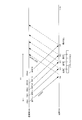
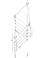
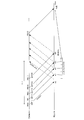
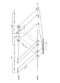
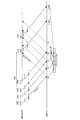
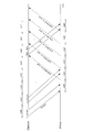
- FIG. 1 Diagram showing an example of HARQ operation Block diagram showing a partial configuration example of the base station according to the first embodiment Block diagram showing a partial configuration example of the terminal according to the first embodiment Block diagram showing an example of the configuration of the base station according to the first embodiment Block diagram showing an example of the configuration of the terminal according to the first embodiment
- NTN Non-Terrestrial Network
- NR is being considered for extension to non-terrestrial networks (NTN: Non-Terrestrial Network) such as communications using satellites and / or high-altitude platform stations (HAPS) (for example, non-Terrestrial Network).
- HAPS high-altitude platform stations
- a satellite coverage area eg, one or more cells
- a ground terminal also called a UE (User Equipment)
- an aircraft terminal is formed by a beam from the satellite.
- the round-trip time of radio wave propagation between the terminal and the satellite is determined by the altitude of the satellite (for example, up to about 36000 km) and / or the angle seen from the terminal.
- Non-Patent Document 1 describes that the propagation delay time between a satellite and a terminal, that is, the round-trip propagation time (RTT: Round Trip Time) takes about 544 ms at the maximum.
- RTT Round Trip Time
- HARQ hybrid automatic repeat request
- LTE or NR for example, HARQ (hybrid automatic repeat request) is applied to retransmission control at the time of data transmission.
- the transmitting side transmits data after performing channel coding (FEC: Forward Error Correction) such as turbo coding or LDPC (Low Density Parity Check) coding, for example.
- FEC Forward Error Correction
- LDPC Low Density Parity Check
- the receiving side saves the received data (for example, a soft judgment value) in a buffer (in other words, also referred to as buffering, storage or retention) when there is an error in the received data at the time of data decoding.
- the buffer is also referred to as, for example, a HARQ soft buffer or simply a soft buffer.
- the receiving side When retransmitting data, the receiving side synthesizes (soft-synthesizes) the received data (in other words, the retransmission data or the data related to the retransmission request) and the previously received data (in other words, the saved data), and decodes the synthesized data. ..
- the receiving side can decode using data with improved reception quality (for example, SNR: Signal to Noise Ratio). Further, in HARQ, the transmitting side can improve the coding gain by transmitting a parity bit different from that at the time of the previous transmission (in other words, a different RV (Redundancy version)). Further, in HARQ, continuous data transmission is possible by using a plurality of processes (also referred to as HARQ processes) in consideration of the propagation path delay or the processing delays on the transmitting side and the receiving side (for example, also referred to as HARQ process). For example, see FIG. 1). In this case, the receiving side stores the received data in the buffer separately for each process ID (sometimes referred to as "PID") which is identification information for identifying the process (or data).
- PID process ID
- the base station notifies the terminal of information about HARQ including process ID, NDI (New Data Indicator), RV, etc. at the time of data allocation.
- the terminal performs data reception processing (for example, software synthesis processing, etc.) based on the information regarding HARQ notified from the base station.
- NTN which is a cell environment with a large propagation delay (or RTT) compared to the terrestrial network
- RTT propagation delay
- the number of processes in the RTT is large, so the amount of soft buffer (in other words, software) provided on the receiving side (for example, terminal) Buffer size) can be large.
- the amount of soft buffer increases, for example, the cost of the device on the receiving side (terminal), the chip size, and the like may increase.
- the number of processes in the RTT when the number of processes in the RTT is reduced, the amount of soft buffer provided on the receiving side (for example, the terminal) can be reduced. However, if the number of processes in RTT is reduced, the throughput per user (in other words, the terminal) (for example, also referred to as maximum user throughput) may decrease.
- the upper layer for example, RLC (RadioLink Control) layer
- the combined gain cannot be obtained and the delay becomes large as compared with HARQ.
- the user experience may be deteriorated due to the delay of various network controls or the delay of user data.
- retransmission control will be described when the propagation delay between the terminal and the base station is large as compared with the terrestrial network environment, for example, in the NTN environment.
- appropriate retransmission control can be realized for each of different data (for example, data of different processes).
- the communication system includes, for example, a base station 100 and a terminal 200.
- the base station 100 (corresponding to a transmitting device) transmits data (for example, also referred to as downlink data or PDSCH (Physical Downlink Shared Channel)).
- the terminal 200 (corresponding to the receiving device) receives the data and feeds back the response signal to the data.
- the response signal is also referred to as, for example, an ACK (Acknowledgement) / NACK (Negative acknowledgment) signal or ACK / NACK information.
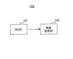
- FIG. 2 is a block diagram showing a partial configuration example of the base station 100 according to the embodiment of the present disclosure.
- the control unit 101 generates control information (for example, buffer priority information) regarding buffering for retransmission control.
- the wireless transmission unit 103 transmits data and control information.
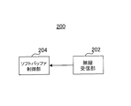
- FIG. 3 is a block diagram showing a partial configuration example of the terminal 200 according to the embodiment of the present disclosure.
- the wireless reception unit 202 receives control information (for example, buffer priority information) regarding buffering for retransmission control.
- the soft buffer control unit 204 controls buffering based on the control information.
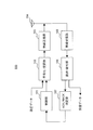
- FIG. 4 is a block diagram showing an example of the configuration of the base station 100 according to the present embodiment.
- the base station 100 includes, for example, a control unit 101, a coding / modulation unit 102, a radio transmission unit 103, an antenna 104, a radio reception unit 105, a demodulation / decoding unit 106, and an ACK / NACK determination unit 107. , including.
- the control unit 101 generates, for example, control information (for example, data allocation information) for the terminal 200 and outputs it to the coding / modulation unit 102.
- the control information includes, for example, time resource and frequency resource allocation information (also referred to as time / frequency resource allocation information), coding rate and modulation method information (for example, also referred to as MCS (Modulation and Coding Scheme) information), and , Information about HARQ (also referred to as HARQ information, for example) may be included.
- HARQ information may include, for example, process ID, NDI and RV. Further, the HARQ information includes "buffer priority" indicating the priority of buffering a buffer (for example, the soft buffer 205 shown in FIG. 5) included in the terminal 200 between a plurality of data (for example, data of different processes). Information (BPF: BufferPriorityFlag) ”may be included. An example of BPF will be described later.
- control unit 101 controls the retransmission of the transmission data based on the ACK / NACK determination result input from the ACK / NACK determination unit 107. For example, the control unit 101 outputs a retransmission instruction to the coding / modulation unit 102 in the case of NACK, and outputs a data discard instruction to the coding / modulation unit 102 in the case of ACK.
- the coding / modulation unit 102 encodes and modulates the input transmission data (for example, data related to new transmission (also simply referred to as new data) or initial transmission data), and transmits the modulated signal to the radio transmission unit 103. Output.
- the data coding method may be, for example, error correction coding such as a turbo code, an LDPC code, and a polar code.
- the data modulation method may be, for example, QPSK (Quadrature Phase Shift Keying), QAM (Quadrature Amplitude Modulation), or the like.
- the coding / modulation unit 102 encodes and modulates the control information input from the control unit 101, and outputs the modulated signal to the wireless transmission unit 103.
- the coding / modulation unit 102 holds, for example, the transmitted data that has been transmitted, and when the control unit 101 outputs a retransmission instruction (in other words, when there is an error in the transmitted data), the held data. (In other words, the resent data) is subjected to the same processing as the above-mentioned processing. Further, for example, when the control unit 101 outputs a data discard instruction (in other words, when there is no error in the transmitted data), the coding / modulation unit 102 discards the held data.
- the retransmission unit of the transmitted data may be, for example, a transport block unit, a code block unit, a code block group unit, or another data unit.
- the transmitted data corresponds to PDSCH
- the data allocation information corresponds to DCI (Downlink Control Information) or PDCCH (Physical Downlink Control Channel).
- the wireless transmission unit 103 performs transmission processing such as D / A conversion, up-conversion, and amplification on the signal input from the coding / modulation unit 102, and transmits the wireless signal obtained by the transmission processing to the antenna 104. Send from.
- the wireless reception unit 105 performs reception processing such as down-conversion and A / D conversion on the signal from the terminal 200 received via the antenna 104, and outputs the signal after the reception processing to the demodulation / decoding unit 106.
- the signal from the terminal 200 includes, for example, a data signal (for example, also referred to as uplink data or PUSCH (Physical Uplink Shared Channel)) and an ACK / NACK signal.
- the demodulation / decoding unit 106 performs, for example, channel estimation, demodulation, and decoding processing on the signal input from the wireless reception unit 105.
- the demodulation / decoding unit 106 outputs a data signal (in other words, received data) included in the received signal, and outputs an ACK / NACK signal included in the received signal to the ACK / NACK determination unit 107.
- the ACK / NACK determination unit 107 determines ACK or NACK for the transmitted transmission data (for example, a transport block) based on the ACK / NACK signal input from the demodulation / decoding unit 106.
- the ACK / NACK determination unit 107 outputs the determination result to the control unit 101.
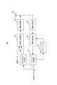
- FIG. 5 is a block diagram showing an example of the configuration of the terminal 200 according to the present embodiment.
- the terminal 200 includes, for example, an antenna 201, a wireless reception unit 202, a demodulation / decoding unit 203, a soft buffer control unit 204, a soft buffer 205, an ACK / NACK generation unit 206, and a coding / modulation unit 207.
- the wireless transmitter 208 and the like.
- the wireless reception unit 202 performs reception processing such as down-conversion and A / D conversion on the signal from the base station 100 received via the antenna 201, and includes the reception signal (for example, data and control information) after the reception processing. ) Is output to the demodulation / decoding unit 203.
- the demodulation / decoding unit 203 demodulates and error-corrects and decodes the received signal input from the wireless reception unit 202, and outputs the decoded signal to the soft buffer control unit 204.
- the demodulation / decoding unit 203 demodulates and decodes the received data included in the received signal based on the modulation method and coding rate shown in the control information (for example, data allocation information) included in the received signal. Error correction and decoding may be performed.
- the demodulation / decoding unit 203 outputs the decoded signal to the soft buffer control unit 204.
- the demodulation / decoding unit 203 determines, for example, whether the received data is new data or retransmission data based on the NDI included in the control information. When the received data is new data, the demodulation / decoding unit 203 performs an error correction / decoding of the received data and makes a CRC (Cyclic Redundancy Check) determination. Further, the demodulation / decoding unit 203 synthesizes the saved data and the data received this time when the received data is retransmission data and the data received up to the previous reception is saved in the soft buffer 205. Later, the composite data is error-corrected and decoded.
- CRC Cyclic Redundancy Check
- the demodulation / decoding unit 203 performs error correction / decoding of the data received this time and performs CRC determination without performing the synthesis process. Further, the demodulation / decoding unit 203 outputs the result of the CRC determination to the soft buffer control unit 204.
- the soft buffer control unit 204 discards the received data saved in the past by the corresponding process ID (in other words). Then, Flush) is instructed to the soft buffer 205.
- the soft buffer control unit 204 is based on the buffer priority information (BPF) included in the signal input from the demodulation / decoding unit 203. , Controls the buffering of received data into the soft buffer 205.
- BPF buffer priority information
- the soft buffer control unit 204 controls the storage of the received data in the soft buffer 205 and the destruction of the received data based on the BPF.
- the soft buffer control unit 204 instructs the soft buffer 205 to save the received data.
- An operation example of the soft buffer control unit 204 will be described later.
- the soft buffer control unit 204 outputs the CRC determination result input from the demodulation / decoding unit 203 to the ACK / NACK generation unit 206. Further, the soft buffer control unit 204 outputs the corresponding received data when the CRC determination result is CRC OK.
- the soft buffer 205 is a buffer for storing data (for example, a soft determination value) received in the past by the terminal 200.
- the stored data is used, for example, for HARQ synthesis.
- the soft buffer 205 stores, for example, the received data for each HARQ process.
- the soft buffer 205 does not have to include buffers for the number of processes corresponding to RTT.
- the buffer size of the soft buffer 205 may be smaller than the buffer size corresponding to the number of processes corresponding to RTT.
- the ACK / NACK generation unit 206 generates an ACK / NACK signal based on the CRC determination result input from the soft buffer control unit 204. For example, the ACK / NACK generation unit 206 generates ACK in the case of CRC OK (no error) and NACK in the case of CRC NG (with error). The ACK / NACK generation unit 206 outputs the generated ACK / NACK signal to the coding / modulation unit 207.
- the ACK / NACK generation unit 206 When a plurality of transport blocks or code blocks are transmitted, the ACK / NACK generation unit 206 generates an ACK / NACK signal for each transport block or each code block, and generates a plurality of ACK / NACK signals. An ACK / NACK code block containing a signal may be generated.
- the coding / modulation unit 207 performs error correction coding and modulation of transmission data (in other words, uplink data or PUSCH), and outputs the modulated signal to the wireless transmission unit 208. Further, the coding / modulation unit 207 performs error correction coding and modulation of the ACK / NACK signal input from the ACK / NACK generation unit 206, and outputs the modulated signal to the radio transmission unit 208.
- the wireless transmission unit 208 performs transmission processing such as D / A conversion, up-conversion, and amplification on the signal input from the coding / modulation unit 207, and transmits the wireless signal obtained by the transmission processing to the antenna 201. Send from.
- the terminal 200 When the received data has an error (for example, in the case of CRCNG), the terminal 200 (in other words, the receiving side) saves the received data in the soft buffer 205 and waits for the corresponding data to be resent. On the other hand, the terminal 200 does not have to store the received data in the soft buffer 205 when there is no error in the received data (for example, in the case of CRC OK). In other words, the terminal 200 uses the soft buffer 205 when there is an error in the received data (for example, the received packet).
- the propagation path fluctuation is smaller than that in the ground network environment. Therefore, in the NTN environment, it is highly possible to realize a low error rate (for example, also called BLER (Block Error Rate) or packet error rate) as compared with the terrestrial network environment.
- BLER Block Error Rate
- the number of cases where the terminal 200 uses the soft buffer 205 is smaller than that in the terrestrial network environment.
- the terminal 200 may use the number of buffers in the soft buffer 205, which is the product of the number of processes for RTT and BLER on average.
- the terminal 200 is on average. May use buffers for about 6 processes.
- HARQ can be realized by the soft buffer 205, which is smaller than the soft buffer size for the number of processes corresponding to RTT.
- the buffer size of the soft buffer 205 may be smaller than, for example, the buffer size for the number of processes corresponding to RTT.
- high-priority data transmission such as control packets or important user data is transmitted with low delay by the combined gain of HARQ so as not to impair the user's experience.
- low priority data transmission may be applied to which the combined gain of HARQ is not obtained, for example, retransmission of the MAC layer or higher layer.
- the buffer priority information (BPF) indicating the priority of buffering data to the soft buffer 205 is notified from the base station 100 to the terminal 200.
- the BPF indicates the priority regarding the use of the soft buffer 205 between a plurality of data, or the priority of the synthesis process by HARQ.
- the base station 100 generates a BPF for the assigned data for the terminal 200 at the time of data transmission allocation, and notifies the terminal 200 of the BPF.
- the terminal 200 controls the storage of received data (in other words, data synthesis processing) in the soft buffer 205 based on the BPF.
- the BPF may be 1-bit information (for example, 0 or 1).
- the high-priority data is, for example, data including a control message of a higher layer such as RRC (Radio Resource Control), or data for a high-priority Logical Channel.
- the data having a low priority may be data having a stricter delay requirement such as data for a streaming service such as audio data or video data. This is because there is a case where the data is not retransmitted when the delay request is stricter, so that the need for storage in the soft buffer 205 is low.
- the data having a high priority and the data having a low priority are not limited to these, and may be other types of data.
- the terminal 200 stores the received data in the soft buffer 205 if there is space in the soft buffer 205, and stores the received data in the soft buffer 205. If there is no free space, the received data is discarded without being saved in the soft buffer 205.
- the terminal 200 when the soft buffer 205 is completely used for other data (in other words, when there is no free space), the terminal 200 corresponds to the data having a low priority among the data stored in the soft buffer 205. Discard the saved data and save the high priority data (in other words, overwrite save). In other words, when the soft buffer 205 is full, the terminal 200 overwrites the data having a lower priority than the received data with the received data.
- the terminal 200 discards the received data if, for example, the soft buffer 205 is completely used for other data and there is no low priority data in the data stored in the soft buffer 205.
- 6 and 7 show an example of the saving operation in the soft buffer 205.
- the soft buffer 205 has a buffer for three processes.
- the number of processes corresponding to the data that can be stored in the soft buffer 205 is smaller than the number of processes corresponding to RTT.
- the buffer size of the soft buffer 205 is not limited to the buffer size for three processes, and may be another size.
- the soft buffer 205 is in a fully used state (in other words, there is no free space).
- PID41 data is saved in the soft buffer 205.
- the terminal 200 uses the data of the older process ID (data of PID2 in FIG. 6) among the low-priority data stored in the soft buffer 205 as the data of high priority (data of PID41 in FIG. 6). ) May be overwritten and saved.
- CRCNG error
- the terminal 200 discards the data of PID 41 without saving it. In other words, the terminal 200 does not discard the data stored in the soft buffer 205.
- the terminal 200 can use, for example, a soft buffer 205 having a size smaller than the soft buffer size corresponding to the number of processes corresponding to RTT.
- the size of the soft buffer 205 included in the terminal 200 can be suppressed even when the number of processes in the RTT is large as in the NTN environment. Therefore, according to this embodiment, for example, the chip size or cost of the terminal 200 can be reduced.
- the priority for example, BPF
- the priority for example, BPF
- HARQ synthesis the priority for buffering the transmission data to the soft buffer 205
- BPF buffering for retransmission control
- the terminal 200 can preferentially buffer the data having a higher priority in the soft buffer 205 and perform HARQ synthesis even when the soft buffer 205 is full. Therefore, according to the present embodiment, the HARQ composite gain can be preferentially obtained for the high-priority data, so that the probability of successful reception of the high-priority data can be improved and the user experience can be improved.
- the base station 100 and the terminal 200 can appropriately perform retransmission control according to the priority of buffering for each of the data of different processes. Therefore, for example, even if the size of the soft buffer 205 is smaller than the number of processes corresponding to the RTT length, the base station 100 can continuously transmit data without reducing the number of processes in the RTT. Therefore, according to the present embodiment, it is possible to suppress a decrease in throughput per user (for example, maximum user throughput).
- the data overwritten by other data in the soft buffer 205 (for example, the data of PID2 in FIG. 6) and the data not stored in the soft buffer 205 (for example, the data of PID41 in FIG. 7) are discarded by the terminal 200. Will be done. In other words, HARQ synthesis does not apply to these data. In this case, normal retransmission (ARQ) may be applied to these data. In ARQ, for example, retransmission is performed based on the ACK / NACK signal, and signal synthesis is not performed on the receiving side (for example, terminal 200). Alternatively, for example, retransmission of a higher layer (for example, RLC layer) may be applied to these data.
- ARQ normal retransmission
- the retransmission of the upper layer has a larger delay than the HARQ.
- BPF 0
- normal retransmission or higher layer retransmission is not premised on synthesis instead of HARQ for the data. Even if is applied, for example, deterioration of the user's experience can be suppressed.
- the NDI value that is, the content (or meaning) indicated by the BPF differs depending on the new transmission and the retransmission will be described.
- the meaning indicated by the BPF and the operation of the terminal 200 are executed. It is the same as the first form.
- BPF indicates the corresponding data decoding method.
- the BPF includes, for example, information indicating the priority of buffering new data into the soft buffer 205, and information indicating whether or not to perform synthesis processing on the retransmission data.
- error after error correction / decoding for example, CRCNG
- the processing of the terminal 200 can be further simplified.
- FIGS. 4 and 5 Since the base station and the terminal according to the present embodiment have the same basic configuration as the base station 100 and the terminal 200 according to the first embodiment, FIGS. 4 and 5 will be referred to for description.
- the number of notification bits of the process ID can be reduced. For example, if the RTT is 512ms and the TTI length is 1ms, there are 512 processes in the RTT, and the number of bits for notification of the process ID is 9 bits. In the present embodiment, for example, by setting (in other words, limiting) the number of process IDs to be notified to 64, the number of notification bits of the process ID can be reduced to 6 bits.
- the receiving side (for example, terminal 200) has the received data and different data stored in the soft buffer 205 (in other words, the process). There is a possibility that the ID will be combined with the process ID of the received data).
- the present embodiment a method of avoiding the synthesis of different data having the same process ID by notifying the information regarding the use of the soft buffer by the BPF notified from the base station 100 to the terminal 200 will be described.
- the content notified by the BPF differs between the present embodiment and the first embodiment.
- the base station 100 (for example, the control unit 101) uses the process IDs in order for data transmission to the terminal 200 (for example, see FIG. 5) in the RTT, and uses all the process IDs. Use (reuse) the used process ID for. As a result, the same process ID may be assigned to different data.
- the base station 100 assigns the used process ID to the data
- BPF 0 is set for.
- the base station 100 transmits data (for example, new data or retransmission data) and BPF for the data to the terminal 200.
- data for example, new data or retransmission data
- BPF for the data
- error for example, CRCNG
- BPF the terminal 200 stores the data stored in the soft buffer 205 with the same process ID as the process ID of the received data. Is discarded and the received data is saved in the soft buffer 205. Further, when the soft buffer 205 does not have the saved data having the same process ID as the process ID of the received data, the terminal 200 saves the received data in the soft buffer 205.
- the BPF indicates the priority of buffering the soft buffer 205 between different data associated with the same process ID for the HARQ process (in other words, the retransmission control process).
- the soft buffer 205 has a buffer for three processes.
- the number of processes corresponding to the data that can be stored in the soft buffer 205 is smaller than the number of processes corresponding to RTT.
- the buffer size of the soft buffer 205 is not limited to the buffer size for three processes, and may be another size.
- the data of the first PID 10 has an error (for example, CRCNG) in the decoding result at the terminal 200 and is stored in the soft buffer 205.
- BPF 0 (priority: low) notified to the terminal 200 when the data of the first PID 10 is transmitted.
- FIG. 9 shows the terminal 200 notified when the data of the second PID 10 is transmitted.
- BPF 0 (priority: low).
- the terminal 200 discards the data of the first PID10 stored in the soft buffer 205 and discards the data of the second PID10. Save the data (overwrite).
- the terminal 200 stores the received data in the soft buffer 205 when the decoding result for the retransmission data is an error (for example, CRCNG).
- an error for example, CRCNG
- the terminal 200 stores (in other words, HARQ synthesis) the data of any of the different data using the same process ID in the soft buffer 205. ) Can be prioritized. In other words, in the present embodiment, the terminal 200 can prevent different data using the same process ID from being combined at the time of retransmission.
- the efficiency of HARQ can be improved while reducing the number of notification bits (in other words, control overhead) of the process ID. Therefore, according to the present embodiment, it is possible to realize an appropriate retransmission control process according to the radio propagation environment.
- different data associated with the same process ID are transmitted in different segments among the plurality of segments.
- data with the same process ID in different segments is treated as different data.
- FIG. 10 is a diagram showing an operation example according to the first modification of the second embodiment.
- the RTT section is divided into a plurality of segments (in FIG. 8, four segments seg0 to seg3). For example, as shown in FIG. 10, seg0 to seg3 are repeatedly set with RTT as a cycle.
- the terminal 200 stores, for example, data of the same process ID in different segments as different data in the soft buffer 205. In other words, the terminal 200 stores the received data in the soft buffer 205 based on the combination of the segment and the process ID.
- the terminal 200 saves the received data of seg0 and PID0 in the soft buffer 205 and sets the PID0. It is assumed that the data retransmission is transmitted during the period of seg0, which is the same segment of the next RTT interval.
- the terminal 200 receives the data of the same process ID (for example, the data of PID1 shown in FIG. 10) in different segments (for example, seg0 and seg1 shown in FIG. 10), the terminal 200 receives the data as different data.
- the terminal 200 receives each received data (for example, the data of seg0 and PID1).
- the data of seg1 and PID1) are stored individually in the soft buffer 205.
- the terminal 200 manages the soft buffer 205 based on the segment and the process ID.
- the process ID in the segment may be notified, so that the notification bit of the process ID can be reduced.
- the RTT is 512ms
- the TTI length is 1ms
- four segments with a segment length of 128ms are set
- the maximum number of processes in the segment is 128. Therefore, for example, in the case of the process ID corresponding to the RTT length, the number of notification bits is 9 bits, whereas in the modification 1 of the second embodiment, the number of notification bits of the process ID is 7 bits. , The number of notification bits can be reduced.
- the process ID may be reused in the segment by combining the modification 1 and the second embodiment.
- the process ID may be reused in the segment by combining the modification 1 and the second embodiment.
- the segment length is 128 ms and the maximum number of processes is 128)
- 16 process IDs may be notified.
- the number of notification bits of the process ID is 4 bits, and the number of notification bits can be further reduced.
- the process ID when reusing the process ID in the segment, for example, as described in the second embodiment, by using the BPF, it is possible to avoid synthesizing different data in the terminal 200, and the priority is high. HARQ synthesis of data is possible.
- the terminal 200 does not save the received data in the soft buffer 205 even if the decoding result of the received data is an error.
- the BPF for the data retransmitted in the different segment is a synthesis process (in other words, in other words,) for the data. Indicates that the storage in the soft buffer 205) is not performed.
- the data of PID1 at seg0 of a certain RTT is originally retransmitted at seg0 after the lapse of RTT.
- the base station 100 transmits the retransmission data for the data of PID1 in seg1 in seg1 without BPF.
- different data with PID1 associated with seg1 are transmitted.
- the terminal 200 synthesizes the retransmission data of PID1 transmitted in seg1 without BPF and the stored data of PID1 of seg1 stored in the soft buffer 205.
- the base station 100 can retransmit the data while avoiding the synthesis of different data even when the base station 100 straddles the segments, so that the delay can be reduced even when the data cannot be transmitted within the same segment. For example, it is possible to prevent the occurrence of a delay of 1 RTT or more.
- segment lengths in the RTT may all be the same, and at least some of the segment lengths may be different (short or long).
- the transmission timing of each process is predetermined. For example, after some data has been transmitted, the corresponding retransmission data has been transmitted after the RTT has elapsed. In this way, in synchronous HARQ, since the data transmission timing is determined in advance, it is not necessary to notify the process ID. On the other hand, in synchronous HARQ, since the transmission timing is determined, the flexibility of scheduling (for example, data allocation to each terminal) is reduced. Further, for example, by notifying the process ID, the flexibility of scheduling can be improved, but the amount of control data for notifying the process ID increases.
- the process ID is set based on the slot number and the relative value from the slot number (in other words, the offset value with respect to the slot number, which is sometimes called the process ID relative value). You will be notified. As a result, the flexibility of scheduling can be improved while reducing the amount of control data for notifying the process ID.
- the slot number is "n”
- the relative value (offset value) to be notified is "p”
- the number of processes corresponding to RTT is "nRTT”.
- p may be represented by, for example, 4 bits of -8, -7,..., +7.
- the base station 100 notifies the terminal 200 of the 4-bit p. Further, the terminal 200 calculates the process ID intended by the base station 100 according to the equation (1).
- the number of bits of p is not limited to 4 bits, and may be any other number of bits.
- FIG. 11 is a diagram showing an operation example according to the second modification of the second embodiment.
- the value of p may be determined based on the difference in slot numbers corresponding to the time of new transmission and the time of retransmission of data.
- the BPF for the retransmission data indicates that the synthesis process is performed.
- the base station 100 can notify the terminal 200 of the same process ID (for example, PID1) at a timing different from the predetermined transmission timing.
- the value of p corresponds to the slot number (slot 0 in FIG. 12) corresponding to the transmission of the first data stored in the soft buffer 205 of the terminal 200 and the first data. It is determined based on the difference between the PID (PID 0 in FIG. 12) and the slot number (slot 5 in FIG. 12) corresponding to the transmission of the second data associated with the same PID. Further, the BPF for the second data indicates that the second data is buffered in the soft buffer 205.
- the flexibility of scheduling can be improved while reducing the number of notification bits of the process ID.
- the soft buffer 205 has priority over the data having a high priority over the data having a low priority. Because it is used for, the reliability of high-priority data can be improved and the delay can be reduced.
- the slot number is a slot number set by the base station 100 or the system, and may be a number repeated for each system frame.
- the value of n in the equation (1) may be calculated by the following equation (2).
- n slot number + system frame number x (number of slots per system frame) (2)
- the slot number may be a number repeated for each subframe.
- the value of n in the equation (1) may be calculated by the following equation (3).
- n slot number + system frame number x subframe number x (number of slots per subframe) (3)
- the time resource unit is not limited to the slot, and may be another time resource unit (for example, a frame, a subframe, a mini slot, or the like).
- the notification cycle of the ACK / NACK signal may be notified in advance from the base station to the terminal.
- the terminal At the notification timing of the ACK / NACK signal, the terminal collectively transmits, for example, the ACK / NACK signal for the data received after the previous notification timing.
- FIG. 13 shows an operation example of the wireless communication system according to the present embodiment.
- a certain period (for example, RTT) is divided into a plurality of (here, 5) segments (for example, seg0 to seg4), and one ACK / NACK signal is notified for each segment.
- the terminal may hold the ACK / NACK signal generated in the segment and perform the transmission processing of the ACK / NACK signal at the timing of the segment break (in other words, the boundary).
- the terminal 200 may change the notification method of the ACK / NACK signal based on, for example, the traffic status, the transmission path status, or the ACK / NACK signal. For example, there are the following methods for notifying the ACK / NACK signal.
- NTN can realize a low error rate (for example, BLER) because the propagation path fluctuation is smaller than that of the terrestrial network.
- BLER error rate
- the terminal uses the process ID of the data whose ACK / NACK signal is NACK (in other words, the process ID of the data whose decoding result has an error) among the data received in a certain period (for example, a segment). ) Is notified. In other words, in the notification method 1, the terminal does not notify the process ID of the data whose ACK / NACK signal is ACK among the data received in a certain period.
- ACK / NACK signals are collectively transmitted every 64 ms.
- the terminal if the number of processes corresponding to NACK (in other words, the number of data with an error in the decoding result) is set to "nError", the terminal notifies the number of errors and the process ID of the data with an error.
- the number of notification bits is 12 bits, which is less than 64 bits.
- the ACK / NACK signals for the data of each process are represented one by one by the bitmap. For example, when the terminal transmits an ACK / NACK signal collectively every 64 ms, it notifies information for up to 64 bits.
- the notification bit is 66 in the notification method 1.
- the number of bits is equal to or larger than that of the notification method 2 (for example, 64 bits).
- the notification bit is 64 bits in the notification method 1 (when nError ⁇ 10). That is, it is less than the number of notification bits of the notification method 2).
- the terminal uses the notification method 1 (in other words, ACK / NACK notification by the process ID corresponding to NACK) and the notification method 2 (in other words, ACK / NACK by bitmap) depending on the situation. Notification) and.
- the base station sets the notification method of the ACK / NACK signal of each terminal.
- the ACK / NACK signal notification method is, for example, notified from the base station to the terminal.
- the base station may set the ACK / NACK notification method setting for each terminal and notify by a higher layer (for example, RRC reconfiguration message), or set it for each cell and notify by system information. You may.
- the terminal switches between the notification method 1 and the notification method 2 based on the notification from the base station.
- the base station may switch between the notification method 1 and the notification method 2 based on the occurrence frequency of data communication or the state of propagation path fluctuation. For example, the base station sets the notification method 1 when the frequency of occurrence of data notification is low (for example, when the frequency of occurrence is less than the threshold value), and when the frequency of occurrence of data notification is high (for example, the frequency of occurrence is equal to or higher than the threshold value). In the case), the notification method 2 may be set.
- the base station sets the notification method 1 when the propagation path variation is small (for example, when the propagation path variation is less than the threshold value), and when the propagation path variation is large (for example, the propagation path variation is equal to or larger than the threshold value).
- the notification method 2 may be set.
- the criteria for switching the ACK / NACK notification method is not limited to the frequency of data notification occurrence and the status of propagation path fluctuations, and may be other criteria.
- the notification method 1 is set in a situation where the number of notification bits of the ACK / NACK signal tends to be smaller in the notification method 1 than in the notification method 2, and the number of notification bits of the ACK / NACK signal is larger than that of the notification method 1. Any standard may be used as long as the notification method 2 is set in a situation where the number of notification methods 2 is likely to decrease.
- ⁇ Switching method 2> the terminal selects the ACK / NACK notification method.
- the terminal may select, for example, a notification method having a smaller number of notification bits from the notification method 1 and the notification method 2.
- the number of processes to be reported is “nP”
- the number of NACKs is “nN”.
- the number of notification bits of the notification method 1 and the notification method 2 is as follows.
- Number of notification bits for notification method 1 nP bits
- Number of notification bits for notification method 2 nN ⁇ ceil (log2 (nP)) + ceil (log2 (nP)) bits (including notification bits for the number of NACKs)
- ceil indicates an operation that advances after the decimal point.
- the terminal selects the notification method having the smaller number of notification bits from the notification method 1 and the notification method 2 and notifies the base station.
- the base station receives the ACK / NACK signal, for example, based on the notification method of the ACK / NACK signal notified from the terminal.
- FIG. 14 shows an example of a format for notifying an ACK / NACK signal.
- information indicating a notification method is stored in the header portion, and an ACK / NACK signal is stored in the remaining portion (for example, the ACK / NACK information field).
- the number of bits of the header portion is 1 bit
- the notification method 1 or the notification method 2 is specified by the 1-bit header portion (either 0 or 1).
- the number of notification bits of the ACK / NACK signal differs depending on the number of NACKs. Therefore, the base station may determine the number of notification bits (length) of the ACK / NACK signal by, for example, the notification bit of the number of NACKs in the ACK / NACK information field shown in FIG.
- the number of bits of the header portion is 2 bits, and the 2-bit header portion (any of 00, 01, 10, 11) is used to display NACK in addition to the notification method 1 and the notification method 2. None (or no data allocation) is specified.
- the subsequent ACK / NACK information field does not contain information.
- the notification method 2 whether the number of NACKs is less than M1 (header: 10) or M1 or more and less than M2 (header: 11) in the header portion. May be specified. If it is less than M1, the ACK / NACK signal of the ceil (log2 (M1)) bit is stored, and if it is M1 or more and less than M2, the ACK / NACK signal of the ceil (log2 (M2)) bit is stored. .. As a result, the base station can determine the number of bits in the ACK / NACK information field by reading the header portion.
- the type of the number of bits of the ACK / NACK information field (for example, in FIG. 14, four types of the number of bits) may be specified.
- the terminal selects one of the radio resource (for example, time / frequency resource) candidates of the number (4 in FIG. 14) according to the type of the number of bits and transmits the ACK / NACK information.
- the base station blindly detects, for example, one of the number of radio resources corresponding to the type of the number of bits. In this case, since the header and the ACK / NACK information field can be set as the same block for error correction coding, a higher coding gain can be obtained.
- the terminal collectively notifies the base station of the ACK / NACK signals for the plurality of received data, so that the ACK / NACK signal is notified by the notification method having a small number of notification bits. This makes it possible to reduce the overhead of ACK / NACK notification.
- a 1-bit (for example, 1 process) ACK / NACK signal is transmitted each time, it is spread or repeated a plurality of times in order to receive the ACK / NACK signal at the error rate required by the base station (sufficiently low error rate).
- the amount of wireless resources used for transmission etc. can be large.
- the ACK / NACK signals are collectively fed back, an error correction coding gain or a diversity gain can be obtained, and the utilization efficiency of the radio resource can be improved.
- the reduction in the number of notification bits enables a more robust transmission method (for example, transmission with a lower code rate) for ACK / NACK notification.
- Reliability can be improved.
- NTN uses long-distance transmission, so improving reliability is important.
- the base station may notify the feedback cycle of the ACK / NACK signal
- the terminal may notify the ACK / NACK signal based on the feedback cycle.
- the third embodiment may be combined with at least one of the first embodiment and the second embodiment, for example.
- the terminal 200 by combining the first embodiment and the third embodiment, the terminal 200 (see, for example, FIG. 5) has a BPF (in other words, priority) notified from the base station 100 (see, for example, FIG. 4).
- Data storage in other words, HARQ synthesis
- the terminal 200 can reduce the number of notification bits by collectively feeding back the ACK / NACK signals to the base station 100 as in the third embodiment.
- the terminal 200 notifies from the base station 100 (see, for example, FIG. 4) even when the process ID is reused in the RTT. Based on the BPF to be generated, HARQ of high-priority data can be appropriately performed without synthesizing different data with the same process ID. Further, the terminal 200 can reduce the number of notification bits by collectively feeding back the ACK / NACK signals to the base station 100 as in the third embodiment.
- the terminal may further collectively transmit ACK / NACK signals for each segmented section (for example, referred to as a “subsegment”).
- the segment is further divided into four subsegments, and the base station and the terminal may set or select an ACK / NACK notification method for each subsegment.
- the base station and the terminal may set or select an ACK / NACK notification method for each subsegment.
- a header portion may be added for each subsegment.
- a different notification method can be set for each sub-segment.
- the notification method 1 may be set during the period of the sub-segment where the errors are concentrated, and the notification method 2 may be set during the period of another sub-segment.
- the ACK / NACK notification method having a smaller number of notification bits is selected for each period finer than the segment, the ACK / NACK notification bits can be further reduced.
- information indicating whether or not the terminal 200 has stored (or stored) data in the soft buffer 205 may be notified to the base station 100 together with the ACK / NACK signal. ..
- the terminal 200 may notify the base station 100 of the DTX (that is, neither ACK nor NACK is sent) when the data is not stored in the soft buffer 205.
- the base station 100 may determine the transmission parameter at the time of retransmission based on the notified information. For example, for data not stored in the soft buffer 205 at the terminal 200, the base station 100 may retransmit the same RV so that the terminal 200 can receive the same as the previous transmission, and Systematic Bit (in other words). Then, the RV including the original information bit) may be transmitted.
- the base station 100 may transmit a different RV to the data stored in the soft buffer 205 in the terminal 200, and transmits an RV that does not include the Systematic Bit or has a low ratio of the Systematic Bit. May be good. Further, when the terminal 200 does not save the data in the soft buffer 205, the information indicating that the data is not saved may be notified to reduce the amount of notification information.
- the BPF may be explicitly notified in the allocation information included in DCI or PDCCH, or implicitly notified by other parameters. You may.
- the BPF is the DCI format used for the terminal 200, the RNTI (Radio Network Temporary ID) used for scrambling the PDCCH, or the search space where the PDCCH was transmitted and the time called CORESET. - May be notified by frequency resources.
- the BPF may be notified by the process ID specially defined in the process ID field.
- the specific process ID may be determined in advance, or may be notified from the base station 100 to the terminal 200 by system information or the like.
- the BPF may be notified by the Logical Channel ID.
- the priority for each Logical Channel ID may be determined in advance, or the base station 100 may notify the terminal 200.
- the base station 100 notifies the Logical Channel ID by DCI every time data is transmitted, so that the terminal 200 can specify the Logical Channel ID (in other words, BPF) before decoding the data.
- each terminal may select a method to be applied according to the terminal capability (UE capability).
- the number of bits of the BPF may be 2 bits or more.
- the soft buffer 205 of the terminal 200 is the high priority data. If it has been used (in other words, if there is no space, or if there is no low-priority stored data), the terminal 200 may perform the following operations. For example, the terminal 200 may discard the oldest data stored in the soft buffer 205 and store the received data this time. Alternatively, the terminal 200 may discard the received data this time without saving it, and may not give an ACK / NACK notification. In other words, the terminal 200 may operate as if the data was not transmitted this time. In this case, since the base station 100 does not have the ACK / NACK notification, the same data may be retransmitted as new data (NDI toggle notification).
- the terminal operation is not specified and may be set according to the implementation of the terminal 200. For example, the operation may be different for each terminal.
- one embodiment of the present disclosure can be applied regardless of the type of satellite such as GEO (Geo-stationary Earth Orbit), MEO (Medium Earth Orbit), LEO (Low Earth Orbit) or HAPS. Further, one embodiment of the present disclosure is not limited to NTN, but also for a terrestrial network in an environment where the cell size is large and the propagation delay between the base station and the terminal is long (for example, an environment in which the propagation delay is equal to or greater than the threshold value). Applicable.
- the ACK / NACK signal may be referred to as HARQ-ACK or HARQ-Feedback information.
- the error rate can be improved by transmitting data from the base station multiple times and synthesizing HARQ at the terminal.
- BPF notifications may only be applied to HARQ processes with HARQ-Feedback disabled.
- notification of HARQ-related information such as RV information is not required. Therefore, by notifying BPF instead, notification is possible without increasing the control information data size.
- the downlink data transmission from the base station to the terminal has been described, but the present invention is not limited to this, and can be applied to the uplink data transmission from the terminal to the base station.
- the necessity of data retention in the terminal transmission buffer may be instructed by notifying the BPF together with the uplink data allocation notification from the base station to the terminal.
- the BPF is notified by DCI.
- the terminal may notify the base station of the BPF together with the uplink transmission data to indicate whether or not the data should be retained in the reception buffer of the base station.
- the BPF is notified by UCI (Uplink Control Information).
- each of the above embodiments has been described on the premise of Dynamic scheduling in which data is allocated using DCI or PDCCH for each data transmission as downlink and uplink data allocation to the terminal. It can also be applied when using downlink semi-persistent scheduling (SPS) or uplink Configured grant (CG), which allocates wireless resources to terminals.
- SPS downlink semi-persistent scheduling
- CG uplink Configured grant
- the initial transmission data is transmitted by the radio resource allocated periodically in advance, but Dynamic scheduling may be used to allocate the data using DCI or PDCCH at the time of HARQ retransmission. ..
- the BPF may be notified when the base station notifies the terminal of the periodic radio resource allocation (periodicity), or the BPF may be notified by DCI or PDCCH at the time of HARQ retransmission.
- RRC reconfiguration, MAC CE or DCI can be used to notify the periodicity of radio resource allocation.
- the HARQ process is determined by the transmission timing, for the SPS or CG in which the same HARQ process ID is set, the transmission of the initial transmission data to be transmitted using the SPS or CG resource is transmitted.
- the HARQ process may be determined by timing (eg, slot number or segment).
- configuredGrantTimer when using uplink CG, configuredGrantTimer operates after sending the initial data, and CG resources are used until the timer expires (for example, the duration of the timer). Transmission of new initial data from the terminal is prohibited, and only retransmission data is assigned by dynanmic scheduling.
- the configuredGrantTimer may be set to a value equal to or less than RTT, and the data transmitted from the terminal using the CG resource within the duration of the configuredGrantTimer may be treated as retransmission data and the received data may be synthesized.
- the terminal can retransmit data transmission that requires improvement in reliability without waiting for an instruction to allocate the retransmitted data by dynamic scheduling from the base station.
- configuredGrantTimer may be disabled in cases where high reliability is not required. In this case, you may notify the HARQ feedback invalidation or the configuredGrantTimer invalidation by the ConfiguredGrantConfig message that sets the CG.
- one base station may perform the operations of each embodiment for each of the plurality of terminals.
- one terminal may perform the operations of each embodiment with a plurality of base stations.
- the values of the RTT length, the buffer size, the number of processes, the number of process IDs, the number of segments, the BPF, etc. described in each of the above embodiments are examples, and are not limited thereto.
- Each functional block used in the description of the above embodiment is partially or wholly realized as an LSI which is an integrated circuit, and each process described in the above embodiment is partially or wholly. It may be controlled by one LSI or a combination of LSIs.
- the LSI may be composed of individual chips, or may be composed of one chip so as to include a part or all of functional blocks.
- the LSI may include data input and output.
- LSIs may be referred to as ICs, system LSIs, super LSIs, and ultra LSIs depending on the degree of integration.
- the method of making an integrated circuit is not limited to LSI, and may be realized by a dedicated circuit, a general-purpose processor, or a dedicated processor. Further, an FPGA (Field Programmable Gate Array) that can be programmed after the LSI is manufactured, or a reconfigurable processor that can reconfigure the connection and settings of the circuit cells inside the LSI may be used.
- the present disclosure may be realized as digital processing or analog processing. Furthermore, if an integrated circuit technology that replaces an LSI appears due to advances in semiconductor technology or another technology derived from it, it is naturally possible to integrate functional blocks using that technology. There is a possibility of applying biotechnology.
- the communication device may include a wireless transmitter / receiver (transceiver) and a processing / control circuit.
- the wireless transmitter / receiver may include a receiver and a transmitter, or both as functions.
- the radio transmitter / receiver (transmitter, receiver) may include an RF (Radio Frequency) module and one or more antennas.
- the RF module may include an amplifier, an RF modulator / demodulator, or the like.
- Non-limiting examples of communication devices include telephones (mobile phones, smartphones, etc.), tablets, personal computers (PCs) (laptops, desktops, notebooks, etc.), cameras (digital stills / video cameras, etc.).
- Digital players digital audio / video players, etc.
- wearable devices wearable cameras, smart watches, tracking devices, etc.
- game consoles digital book readers
- telehealth telemedicines remote health Care / medicine prescription
- vehicles with communication functions or mobile transportation automobiles, airplanes, ships, etc.
- combinations of the above-mentioned various devices can be mentioned.
- Communication devices are not limited to those that are portable or mobile, but are not portable or fixed, any type of device, device, system, such as a smart home device (home appliances, lighting equipment, smart meters or It also includes measuring instruments, control panels, etc.), vending machines, and any other "Things” that can exist on the IoT (Internet of Things) network.
- a smart home device home appliances, lighting equipment, smart meters or It also includes measuring instruments, control panels, etc.
- vending machines and any other "Things” that can exist on the IoT (Internet of Things) network.
- Communication includes data communication using a combination of these, in addition to data communication using a cellular system, wireless LAN system, communication satellite system, etc.
- the communication device also includes devices such as controllers and sensors that are connected or connected to communication devices that perform the communication functions described in the present disclosure.
- devices such as controllers and sensors that are connected or connected to communication devices that perform the communication functions described in the present disclosure.
- controllers and sensors that generate control and data signals used by communication devices that perform the communication functions of the communication device.
- Communication devices also include infrastructure equipment that communicates with or controls these non-limiting devices, such as base stations, access points, and any other device, device, or system. ..
- the terminal includes a receiving circuit for receiving control information regarding buffering for retransmission control, and a control circuit for controlling the buffering based on the control information.
- control information includes information indicating the priority of the buffering among a plurality of data.
- control circuit controls the storage of the data in the buffer and the destruction of the data based on the information indicating the priority.
- the control circuit when the buffer is full, the control circuit overwrites the data having a lower priority than the received data with the received data.
- control circuit discards the received data when the low priority data does not exist in the buffer.
- control information includes information indicating the priority of the data related to the new transmission, information indicating whether or not to perform a synthesis process on the data related to the retransmission request, and information. including.
- control information includes information indicating the priority of the buffering between different data to which the same identification information regarding the retransmission control process is associated.
- the different data associated with the same identification information is transmitted in a different period among a plurality of periods in which the time interval corresponding to the propagation delay time of the data is divided.
- the control information for the data retransmitted during the period of the above includes information indicating that the synthesis process is not performed on the retransmitted data.
- control circuit determines the identification information based on the time resource and the offset value with respect to the time resource.
- the offset value is determined based on the difference between the numbers of the time resources corresponding to the data related to the new transmission and the data related to the retransmission, and the offset value is determined with respect to the data related to the retransmission.
- the control information includes information indicating that the synthesis process is performed.
- the offset value is the number of the time resource of the first data stored in the buffer of the terminal and the identification information associated with the first data.
- the same identification information is determined based on the difference between the number of the time resource of the second data associated with the second data, and the control information for the second data buffers the second data. Contains information indicating that.
- the terminal further includes a transmission circuit for collectively transmitting response signals for a plurality of data, and the control circuit includes information indicating an error detection result for each of the plurality of data.
- the first method of transmitting the response signal and the second method of transmitting the response signal including information about the data having an error among the plurality of data are switched.
- control circuit switches between the first method and the second method based on the notification from the base station.
- control circuit selects a method having a smaller number of transmission bits of the response signal from the first method and the second method.
- the base station includes a control circuit that generates control information related to buffering for retransmission control, and a transmission circuit that transmits the control information.
- the terminal receives the control information regarding the buffering for the retransmission control, and controls the buffering based on the control information.
- the base station In the transmission method according to the embodiment of the present disclosure, the base station generates control information regarding buffering for retransmission control and transmits the control information.
- One embodiment of the present disclosure is useful for wireless communication systems.
- Base station 101 Control unit 102, 207 Coding / modulation unit 103, 208 Wireless transmission unit 104, 201 Antenna 105, 202 Wireless reception unit 106, 203 Demodulation / decoding unit 107 ACK / NACK judgment unit 200 Terminal 204 Soft buffer control unit 205 Soft buffer 206 ACK / NACK generator
Landscapes
- Engineering & Computer Science (AREA)
- Computer Networks & Wireless Communication (AREA)
- Signal Processing (AREA)
- Mobile Radio Communication Systems (AREA)
- Detection And Prevention Of Errors In Transmission (AREA)
Abstract
La présente invention met en œuvre un traitement de commande de retransmission approprié conformément à un environnement de propagation radio. Le présent terminal est pourvu d'un circuit de réception pour recevoir des informations de commande relatives à la mise en mémoire tampon pour la commande de retransmission, et d'un circuit de commande pour commander la mise en mémoire tampon sur la base des informations de commande.
Priority Applications (3)
| Application Number | Priority Date | Filing Date | Title |
|---|---|---|---|
| US17/604,983 US12119941B2 (en) | 2019-04-25 | 2020-04-20 | Terminal, base station, receiving method, and transmitting method |
| CN202080030776.1A CN113767584B (zh) | 2019-04-25 | 2020-04-20 | 终端、基站、接收方法及发送方法 |
| JP2021516096A JP7560446B2 (ja) | 2019-04-25 | 2020-04-20 | 端末、基地局、受信方法及び送信方法 |
Applications Claiming Priority (2)
| Application Number | Priority Date | Filing Date | Title |
|---|---|---|---|
| JP2019-084513 | 2019-04-25 | ||
| JP2019084513 | 2019-04-25 |
Publications (1)
| Publication Number | Publication Date |
|---|---|
| WO2020218231A1 true WO2020218231A1 (fr) | 2020-10-29 |
Family
ID=72942730
Family Applications (1)
| Application Number | Title | Priority Date | Filing Date |
|---|---|---|---|
| PCT/JP2020/017008 Ceased WO2020218231A1 (fr) | 2019-04-25 | 2020-04-20 | Terminal, station de base, procédé de réception et procédé d'émission |
Country Status (4)
| Country | Link |
|---|---|
| US (1) | US12119941B2 (fr) |
| JP (1) | JP7560446B2 (fr) |
| CN (1) | CN113767584B (fr) |
| WO (1) | WO2020218231A1 (fr) |
Cited By (1)
| Publication number | Priority date | Publication date | Assignee | Title |
|---|---|---|---|---|
| JP2024540565A (ja) * | 2021-11-19 | 2024-10-31 | サムスン エレクトロニクス カンパニー リミテッド | フロントホールネットワークを介した堅牢なメッセージ送受信のための方法及び装置 |
Families Citing this family (4)
| Publication number | Priority date | Publication date | Assignee | Title |
|---|---|---|---|---|
| KR102967557B1 (ko) * | 2019-07-15 | 2026-05-20 | 지티이 코포레이션 | 하이브리드 자동 반복 요청 절차를 위한 방법 및 장치 |
| WO2021072658A1 (fr) * | 2019-10-15 | 2021-04-22 | Nokia Shanghai Bell Co., Ltd. | Retransmission en liaison montante sur la base d'un service |
| WO2021193374A1 (fr) * | 2020-03-26 | 2021-09-30 | ソニーセミコンダクタソリューションズ株式会社 | Dispositif de communication et système de communication |
| CN115529630B (zh) * | 2022-11-29 | 2023-03-10 | 广州世炬网络科技有限公司 | 复合通信系统及方法 |
Citations (3)
| Publication number | Priority date | Publication date | Assignee | Title |
|---|---|---|---|---|
| JP2005529518A (ja) * | 2002-06-05 | 2005-09-29 | メシュネットワークス、インコーポレイテッド | 無線アドホック網用のハイブリッドarqとその使用法 |
| JP2008516529A (ja) * | 2004-10-05 | 2008-05-15 | クゥアルコム・インコーポレイテッド | 拡張されたブロック確認応答 |
| WO2016121809A1 (fr) * | 2015-01-29 | 2016-08-04 | 株式会社Nttドコモ | Terminal et système de communication |
Family Cites Families (24)
| Publication number | Priority date | Publication date | Assignee | Title |
|---|---|---|---|---|
| KR100459557B1 (ko) * | 2001-08-23 | 2004-12-03 | 삼성전자주식회사 | 고속 순방향 패킷 접속 통신 시스템에서 데이터 상태정보를 나타내기 위한 혼화 자동 재전송 요구 채널 번호할당 방법 |
| US6744766B2 (en) | 2002-06-05 | 2004-06-01 | Meshnetworks, Inc. | Hybrid ARQ for a wireless Ad-Hoc network and a method for using the same |
| ATE349828T1 (de) * | 2002-08-13 | 2007-01-15 | Matsushita Electric Industrial Co Ltd | Hybrides automatisches wiederholungsaufforderungsprotokoll |
| EP1760927B1 (fr) * | 2003-08-14 | 2020-04-08 | Panasonic Corporation | Surveillance de temps dans la retransmission de paquets pendant un transfert souple |
| ATE390773T1 (de) * | 2004-01-22 | 2008-04-15 | Matsushita Electric Industrial Co Ltd | Verfahren zur harq-wiederholungszeitsteuerung |
| JP4677988B2 (ja) * | 2004-08-10 | 2011-04-27 | 日本電気株式会社 | 通信制御方法、無線通信システム、基地局及び移動局 |
| US20090086657A1 (en) * | 2007-10-01 | 2009-04-02 | Comsys Communication & Signal Processing Ltd. | Hybrid automatic repeat request buffer flushing mechanism |
| US8638732B2 (en) * | 2009-01-07 | 2014-01-28 | Samsung Electronics Co., Ltd. | Apparatus and method for allocating resources using codebook in a broadband wireless communication system |
| KR101551347B1 (ko) * | 2009-01-07 | 2015-09-08 | 삼성전자주식회사 | 광대역 무선통신 시스템에서 코드북을 이용한 자원 할당 장치 및 방법 |
| JP5250061B2 (ja) * | 2011-01-07 | 2013-07-31 | 株式会社エヌ・ティ・ティ・ドコモ | 通信制御方法、移動通信システム及び移動端末装置 |
| JP5982403B2 (ja) * | 2011-01-18 | 2016-08-31 | サムスン エレクトロニクス カンパニー リミテッド | 移動通信システムで端末の性能を報告する方法及び装置 |
| CN104040906A (zh) * | 2011-11-08 | 2014-09-10 | 爱立信(中国)通信有限公司 | 用于执行和控制重传的方法及其装置 |
| US10306568B2 (en) * | 2014-04-02 | 2019-05-28 | Lg Electronics Inc. | Method for transceiving signal in wireless communication system and apparatus therefor |
| FR3023665B1 (fr) * | 2014-07-08 | 2016-08-19 | Sagemcom Documents Sas | Procede et dispositif d'enregistrement a distance de programmes video. |
| US9577793B2 (en) * | 2014-09-23 | 2017-02-21 | Intel Corporation | Soft buffer management |
| US9893843B2 (en) * | 2014-12-30 | 2018-02-13 | Mediatek Inc. | Rate matching and soft channel bits storage for superposition coding |
| US20160227540A1 (en) * | 2015-01-30 | 2016-08-04 | Qualcomm Incorporated | Soft buffer management for enhanced carrier aggregation |
| US11831584B2 (en) * | 2015-12-15 | 2023-11-28 | Qualcomm Incorporated | Techniques for indicating a dynamic subframe type |
| JP2019169750A (ja) | 2016-08-10 | 2019-10-03 | 株式会社Nttドコモ | ユーザ装置、及び再送制御方法 |
| CN109644370B (zh) * | 2016-08-31 | 2022-10-04 | 株式会社Ntt都科摩 | 用户终端以及无线通信方法 |
| WO2018138555A1 (fr) | 2017-01-25 | 2018-08-02 | Telefonaktiebolaget Lm Ericsson (Publ) | Détermination de mode de rétroaction harq pour transmission en liaison descendante |
| KR102553624B1 (ko) * | 2017-02-06 | 2023-07-10 | 삼성전자주식회사 | 다수의 뉴멀러지들을 위한 harq 절차를 관리하는 방법 및 사용자 장비(ue) |
| JP6992271B2 (ja) * | 2017-04-06 | 2022-01-13 | 株式会社デンソー | 無線通信端末 |
| US11271687B2 (en) * | 2017-11-17 | 2022-03-08 | Telefonaktiebolaget Lm Ericsson (Publ) | Method and arrangement for enhanced soft buffer handling |
-
2020
- 2020-04-20 WO PCT/JP2020/017008 patent/WO2020218231A1/fr not_active Ceased
- 2020-04-20 US US17/604,983 patent/US12119941B2/en active Active
- 2020-04-20 JP JP2021516096A patent/JP7560446B2/ja active Active
- 2020-04-20 CN CN202080030776.1A patent/CN113767584B/zh active Active
Patent Citations (3)
| Publication number | Priority date | Publication date | Assignee | Title |
|---|---|---|---|---|
| JP2005529518A (ja) * | 2002-06-05 | 2005-09-29 | メシュネットワークス、インコーポレイテッド | 無線アドホック網用のハイブリッドarqとその使用法 |
| JP2008516529A (ja) * | 2004-10-05 | 2008-05-15 | クゥアルコム・インコーポレイテッド | 拡張されたブロック確認応答 |
| WO2016121809A1 (fr) * | 2015-01-29 | 2016-08-04 | 株式会社Nttドコモ | Terminal et système de communication |
Non-Patent Citations (2)
| Title |
|---|
| CATT ET AL.: "Optimization of soft buffer allocation for TDD[ online", 3GPP TSG-RAN WG1#58B R1-094120, XP050388591, Retrieved from the Internet <URL:http://www.3gpp.org/ftp/tsg_ran/WG1_RL1/TSGR1_58b/Docs/R1-094120.zip> * |
| NOKIA NETWORKS: "On UE soft-buffer management for increasing number of CCs[ online", 3GPP TSG-RAN WG1#82B R1-155596, XP051021331, Retrieved from the Internet <URL:http://www.3gpp.org/ftp/tsg_ran/WG1_RL1/TSGR1_82b/Docs/R1-155596.zip> * |
Cited By (3)
| Publication number | Priority date | Publication date | Assignee | Title |
|---|---|---|---|---|
| JP2024540565A (ja) * | 2021-11-19 | 2024-10-31 | サムスン エレクトロニクス カンパニー リミテッド | フロントホールネットワークを介した堅牢なメッセージ送受信のための方法及び装置 |
| US12407448B2 (en) | 2021-11-19 | 2025-09-02 | Samsung Electronics Co., Ltd. | Method and apparatus for robust message transmission reception over fronthaul network |
| JP7751106B2 (ja) | 2021-11-19 | 2025-10-07 | サムスン エレクトロニクス カンパニー リミテッド | フロントホールネットワークを介した堅牢なメッセージ送受信のための方法及び装置 |
Also Published As
| Publication number | Publication date |
|---|---|
| US12119941B2 (en) | 2024-10-15 |
| CN113767584A (zh) | 2021-12-07 |
| CN113767584B (zh) | 2024-01-26 |
| US20220216952A1 (en) | 2022-07-07 |
| JP7560446B2 (ja) | 2024-10-02 |
| JPWO2020218231A1 (fr) | 2020-10-29 |
Similar Documents
| Publication | Publication Date | Title |
|---|---|---|
| JP7560446B2 (ja) | 端末、基地局、受信方法及び送信方法 | |
| US11621803B2 (en) | Hybrid automatic repeat request in non-terrestrial networks | |
| US10972228B2 (en) | Base station device, user equipment, wireless communication system, and communication method | |
| CN111492604A (zh) | 用于非地面通信的系统 | |
| CN110290592A (zh) | 中继传输的方法及用户设备 | |
| US8773975B2 (en) | Network coding enhancements | |
| KR20190001128A (ko) | 효율적인 harq 운영을 위한 방법 및 장치 | |
| WO2021088594A1 (fr) | Procédé et appareil de transmission de données à base de ntn, et support de stockage | |
| CN113067681B (zh) | 一种混合自动重传请求处理方法、通信设备及介质 | |
| CN114556832A (zh) | 基于服务的上行链路重传 | |
| US8675692B2 (en) | Method for acquiring processing time of wireless signal | |
| CN114788205B (zh) | 通信方法及装置 | |
| CN113330762A (zh) | 无线通信的方法及设备 | |
| CN113316922A (zh) | 用于传输数据分组的设备、方法、装置以及计算机可读存储介质 | |
| CN119966585A (zh) | 通信方法及装置 | |
| CN115918199B (zh) | 数据处理方法、装置、设备及存储介质 | |
| KR101140091B1 (ko) | 무선통신 시스템에서 harq 수행 방법 | |
| CN110730054A (zh) | 一种基于harq的业务信道重复发送的重传方法和系统 | |
| US20230361922A1 (en) | Data transmission method and apparatus | |
| US20170230147A1 (en) | Method and apparatus for implementing a retransmission scheme | |
| WO2021184317A1 (fr) | Procédé de détermination de temps utile, terminal et dispositif réseau | |
| WO2024065855A1 (fr) | Rétroaction harq à débit fractionnel | |
| KR102147382B1 (ko) | Harq의 재전송을 위한 방법 및 장치 | |
| KR20100005672A (ko) | 데이터 전송 장치 및 데이터 전송 방법 | |
| WO2023015469A1 (fr) | Transmission coopérative basée sur regroupement d'ue pour cellules in-x 6g |
Legal Events
| Date | Code | Title | Description |
|---|---|---|---|
| 121 | Ep: the epo has been informed by wipo that ep was designated in this application |
Ref document number: 20795022 Country of ref document: EP Kind code of ref document: A1 |
|
| ENP | Entry into the national phase |
Ref document number: 2021516096 Country of ref document: JP Kind code of ref document: A |
|
| NENP | Non-entry into the national phase |
Ref country code: DE |
|
| 122 | Ep: pct application non-entry in european phase |
Ref document number: 20795022 Country of ref document: EP Kind code of ref document: A1 |