WO2020218276A1 - 渦電流式減速装置用ロータ - Google Patents
渦電流式減速装置用ロータ Download PDFInfo
- Publication number
- WO2020218276A1 WO2020218276A1 PCT/JP2020/017151 JP2020017151W WO2020218276A1 WO 2020218276 A1 WO2020218276 A1 WO 2020218276A1 JP 2020017151 W JP2020017151 W JP 2020017151W WO 2020218276 A1 WO2020218276 A1 WO 2020218276A1
- Authority
- WO
- WIPO (PCT)
- Prior art keywords
- rotor
- eddy current
- speed reducer
- content
- current type
- Prior art date
- Legal status (The legal status is an assumption and is not a legal conclusion. Google has not performed a legal analysis and makes no representation as to the accuracy of the status listed.)
- Ceased
Links
Images


Classifications
-
- H—ELECTRICITY
- H02—GENERATION; CONVERSION OR DISTRIBUTION OF ELECTRIC POWER
- H02K—DYNAMO-ELECTRIC MACHINES
- H02K49/00—Dynamo-electric clutches; Dynamo-electric brakes
- H02K49/10—Dynamo-electric clutches; Dynamo-electric brakes of the permanent-magnet type
-
- H—ELECTRICITY
- H02—GENERATION; CONVERSION OR DISTRIBUTION OF ELECTRIC POWER
- H02K—DYNAMO-ELECTRIC MACHINES
- H02K1/00—Details of the magnetic circuit
- H02K1/02—Details of the magnetic circuit characterised by the magnetic material
-
- C—CHEMISTRY; METALLURGY
- C22—METALLURGY; FERROUS OR NON-FERROUS ALLOYS; TREATMENT OF ALLOYS OR NON-FERROUS METALS
- C22C—ALLOYS
- C22C38/00—Ferrous alloys, e.g. steel alloys
- C22C38/001—Ferrous alloys, e.g. steel alloys containing N
-
- C—CHEMISTRY; METALLURGY
- C22—METALLURGY; FERROUS OR NON-FERROUS ALLOYS; TREATMENT OF ALLOYS OR NON-FERROUS METALS
- C22C—ALLOYS
- C22C38/00—Ferrous alloys, e.g. steel alloys
- C22C38/002—Ferrous alloys, e.g. steel alloys containing In, Mg, or other elements not provided for in one single group C22C38/001 - C22C38/60
-
- C—CHEMISTRY; METALLURGY
- C22—METALLURGY; FERROUS OR NON-FERROUS ALLOYS; TREATMENT OF ALLOYS OR NON-FERROUS METALS
- C22C—ALLOYS
- C22C38/00—Ferrous alloys, e.g. steel alloys
- C22C38/02—Ferrous alloys, e.g. steel alloys containing silicon
-
- C—CHEMISTRY; METALLURGY
- C22—METALLURGY; FERROUS OR NON-FERROUS ALLOYS; TREATMENT OF ALLOYS OR NON-FERROUS METALS
- C22C—ALLOYS
- C22C38/00—Ferrous alloys, e.g. steel alloys
- C22C38/04—Ferrous alloys, e.g. steel alloys containing manganese
-
- C—CHEMISTRY; METALLURGY
- C22—METALLURGY; FERROUS OR NON-FERROUS ALLOYS; TREATMENT OF ALLOYS OR NON-FERROUS METALS
- C22C—ALLOYS
- C22C38/00—Ferrous alloys, e.g. steel alloys
- C22C38/06—Ferrous alloys, e.g. steel alloys containing aluminium
-
- C—CHEMISTRY; METALLURGY
- C22—METALLURGY; FERROUS OR NON-FERROUS ALLOYS; TREATMENT OF ALLOYS OR NON-FERROUS METALS
- C22C—ALLOYS
- C22C38/00—Ferrous alloys, e.g. steel alloys
- C22C38/08—Ferrous alloys, e.g. steel alloys containing nickel
-
- C—CHEMISTRY; METALLURGY
- C22—METALLURGY; FERROUS OR NON-FERROUS ALLOYS; TREATMENT OF ALLOYS OR NON-FERROUS METALS
- C22C—ALLOYS
- C22C38/00—Ferrous alloys, e.g. steel alloys
- C22C38/12—Ferrous alloys, e.g. steel alloys containing tungsten, tantalum, molybdenum, vanadium, or niobium
-
- C—CHEMISTRY; METALLURGY
- C22—METALLURGY; FERROUS OR NON-FERROUS ALLOYS; TREATMENT OF ALLOYS OR NON-FERROUS METALS
- C22C—ALLOYS
- C22C38/00—Ferrous alloys, e.g. steel alloys
- C22C38/16—Ferrous alloys, e.g. steel alloys containing copper
-
- C—CHEMISTRY; METALLURGY
- C22—METALLURGY; FERROUS OR NON-FERROUS ALLOYS; TREATMENT OF ALLOYS OR NON-FERROUS METALS
- C22C—ALLOYS
- C22C38/00—Ferrous alloys, e.g. steel alloys
- C22C38/18—Ferrous alloys, e.g. steel alloys containing chromium
- C22C38/22—Ferrous alloys, e.g. steel alloys containing chromium with molybdenum or tungsten
-
- C—CHEMISTRY; METALLURGY
- C22—METALLURGY; FERROUS OR NON-FERROUS ALLOYS; TREATMENT OF ALLOYS OR NON-FERROUS METALS
- C22C—ALLOYS
- C22C38/00—Ferrous alloys, e.g. steel alloys
- C22C38/18—Ferrous alloys, e.g. steel alloys containing chromium
- C22C38/24—Ferrous alloys, e.g. steel alloys containing chromium with vanadium
-
- C—CHEMISTRY; METALLURGY
- C22—METALLURGY; FERROUS OR NON-FERROUS ALLOYS; TREATMENT OF ALLOYS OR NON-FERROUS METALS
- C22C—ALLOYS
- C22C38/00—Ferrous alloys, e.g. steel alloys
- C22C38/18—Ferrous alloys, e.g. steel alloys containing chromium
- C22C38/26—Ferrous alloys, e.g. steel alloys containing chromium with niobium or tantalum
-
- C—CHEMISTRY; METALLURGY
- C22—METALLURGY; FERROUS OR NON-FERROUS ALLOYS; TREATMENT OF ALLOYS OR NON-FERROUS METALS
- C22C—ALLOYS
- C22C38/00—Ferrous alloys, e.g. steel alloys
- C22C38/18—Ferrous alloys, e.g. steel alloys containing chromium
- C22C38/32—Ferrous alloys, e.g. steel alloys containing chromium with boron
-
- C—CHEMISTRY; METALLURGY
- C22—METALLURGY; FERROUS OR NON-FERROUS ALLOYS; TREATMENT OF ALLOYS OR NON-FERROUS METALS
- C22C—ALLOYS
- C22C38/00—Ferrous alloys, e.g. steel alloys
- C22C38/18—Ferrous alloys, e.g. steel alloys containing chromium
- C22C38/40—Ferrous alloys, e.g. steel alloys containing chromium with nickel
- C22C38/42—Ferrous alloys, e.g. steel alloys containing chromium with nickel with copper
-
- C—CHEMISTRY; METALLURGY
- C22—METALLURGY; FERROUS OR NON-FERROUS ALLOYS; TREATMENT OF ALLOYS OR NON-FERROUS METALS
- C22C—ALLOYS
- C22C38/00—Ferrous alloys, e.g. steel alloys
- C22C38/18—Ferrous alloys, e.g. steel alloys containing chromium
- C22C38/40—Ferrous alloys, e.g. steel alloys containing chromium with nickel
- C22C38/44—Ferrous alloys, e.g. steel alloys containing chromium with nickel with molybdenum or tungsten
-
- C—CHEMISTRY; METALLURGY
- C22—METALLURGY; FERROUS OR NON-FERROUS ALLOYS; TREATMENT OF ALLOYS OR NON-FERROUS METALS
- C22C—ALLOYS
- C22C38/00—Ferrous alloys, e.g. steel alloys
- C22C38/18—Ferrous alloys, e.g. steel alloys containing chromium
- C22C38/40—Ferrous alloys, e.g. steel alloys containing chromium with nickel
- C22C38/46—Ferrous alloys, e.g. steel alloys containing chromium with nickel with vanadium
-
- C—CHEMISTRY; METALLURGY
- C22—METALLURGY; FERROUS OR NON-FERROUS ALLOYS; TREATMENT OF ALLOYS OR NON-FERROUS METALS
- C22C—ALLOYS
- C22C38/00—Ferrous alloys, e.g. steel alloys
- C22C38/18—Ferrous alloys, e.g. steel alloys containing chromium
- C22C38/40—Ferrous alloys, e.g. steel alloys containing chromium with nickel
- C22C38/48—Ferrous alloys, e.g. steel alloys containing chromium with nickel with niobium or tantalum
-
- C—CHEMISTRY; METALLURGY
- C22—METALLURGY; FERROUS OR NON-FERROUS ALLOYS; TREATMENT OF ALLOYS OR NON-FERROUS METALS
- C22C—ALLOYS
- C22C38/00—Ferrous alloys, e.g. steel alloys
- C22C38/18—Ferrous alloys, e.g. steel alloys containing chromium
- C22C38/40—Ferrous alloys, e.g. steel alloys containing chromium with nickel
- C22C38/54—Ferrous alloys, e.g. steel alloys containing chromium with nickel with boron
-
- H—ELECTRICITY
- H02—GENERATION; CONVERSION OR DISTRIBUTION OF ELECTRIC POWER
- H02K—DYNAMO-ELECTRIC MACHINES
- H02K49/00—Dynamo-electric clutches; Dynamo-electric brakes
- H02K49/02—Dynamo-electric clutches; Dynamo-electric brakes of the asynchronous induction type
- H02K49/04—Dynamo-electric clutches; Dynamo-electric brakes of the asynchronous induction type of the eddy-current hysteresis type
- H02K49/043—Dynamo-electric clutches; Dynamo-electric brakes of the asynchronous induction type of the eddy-current hysteresis type with a radial airgap
-
- C—CHEMISTRY; METALLURGY
- C21—METALLURGY OF IRON
- C21D—MODIFYING THE PHYSICAL STRUCTURE OF FERROUS METALS; GENERAL DEVICES FOR HEAT TREATMENT OF FERROUS OR NON-FERROUS METALS OR ALLOYS; MAKING METAL MALLEABLE, e.g. BY DECARBURISATION OR TEMPERING
- C21D1/00—General methods or devices for heat treatment, e.g. annealing, hardening, quenching or tempering
- C21D1/18—Hardening; Quenching with or without subsequent tempering
-
- C—CHEMISTRY; METALLURGY
- C21—METALLURGY OF IRON
- C21D—MODIFYING THE PHYSICAL STRUCTURE OF FERROUS METALS; GENERAL DEVICES FOR HEAT TREATMENT OF FERROUS OR NON-FERROUS METALS OR ALLOYS; MAKING METAL MALLEABLE, e.g. BY DECARBURISATION OR TEMPERING
- C21D1/00—General methods or devices for heat treatment, e.g. annealing, hardening, quenching or tempering
- C21D1/26—Methods of annealing
-
- C—CHEMISTRY; METALLURGY
- C21—METALLURGY OF IRON
- C21D—MODIFYING THE PHYSICAL STRUCTURE OF FERROUS METALS; GENERAL DEVICES FOR HEAT TREATMENT OF FERROUS OR NON-FERROUS METALS OR ALLOYS; MAKING METAL MALLEABLE, e.g. BY DECARBURISATION OR TEMPERING
- C21D2211/00—Microstructure comprising significant phases
- C21D2211/002—Bainite
-
- C—CHEMISTRY; METALLURGY
- C21—METALLURGY OF IRON
- C21D—MODIFYING THE PHYSICAL STRUCTURE OF FERROUS METALS; GENERAL DEVICES FOR HEAT TREATMENT OF FERROUS OR NON-FERROUS METALS OR ALLOYS; MAKING METAL MALLEABLE, e.g. BY DECARBURISATION OR TEMPERING
- C21D2211/00—Microstructure comprising significant phases
- C21D2211/004—Dispersions; Precipitations
-
- C—CHEMISTRY; METALLURGY
- C21—METALLURGY OF IRON
- C21D—MODIFYING THE PHYSICAL STRUCTURE OF FERROUS METALS; GENERAL DEVICES FOR HEAT TREATMENT OF FERROUS OR NON-FERROUS METALS OR ALLOYS; MAKING METAL MALLEABLE, e.g. BY DECARBURISATION OR TEMPERING
- C21D2211/00—Microstructure comprising significant phases
- C21D2211/008—Martensite
-
- C—CHEMISTRY; METALLURGY
- C21—METALLURGY OF IRON
- C21D—MODIFYING THE PHYSICAL STRUCTURE OF FERROUS METALS; GENERAL DEVICES FOR HEAT TREATMENT OF FERROUS OR NON-FERROUS METALS OR ALLOYS; MAKING METAL MALLEABLE, e.g. BY DECARBURISATION OR TEMPERING
- C21D6/00—Heat treatment of ferrous alloys
- C21D6/02—Hardening by precipitation
-
- C—CHEMISTRY; METALLURGY
- C21—METALLURGY OF IRON
- C21D—MODIFYING THE PHYSICAL STRUCTURE OF FERROUS METALS; GENERAL DEVICES FOR HEAT TREATMENT OF FERROUS OR NON-FERROUS METALS OR ALLOYS; MAKING METAL MALLEABLE, e.g. BY DECARBURISATION OR TEMPERING
- C21D9/00—Heat treatment, e.g. annealing, hardening, quenching or tempering, adapted for particular articles; Furnaces therefor
- C21D9/0068—Heat treatment, e.g. annealing, hardening, quenching or tempering, adapted for particular articles; Furnaces therefor for particular articles not mentioned below
-
- C—CHEMISTRY; METALLURGY
- C21—METALLURGY OF IRON
- C21D—MODIFYING THE PHYSICAL STRUCTURE OF FERROUS METALS; GENERAL DEVICES FOR HEAT TREATMENT OF FERROUS OR NON-FERROUS METALS OR ALLOYS; MAKING METAL MALLEABLE, e.g. BY DECARBURISATION OR TEMPERING
- C21D9/00—Heat treatment, e.g. annealing, hardening, quenching or tempering, adapted for particular articles; Furnaces therefor
- C21D9/46—Heat treatment, e.g. annealing, hardening, quenching or tempering, adapted for particular articles; Furnaces therefor for sheet metals
-
- Y—GENERAL TAGGING OF NEW TECHNOLOGICAL DEVELOPMENTS; GENERAL TAGGING OF CROSS-SECTIONAL TECHNOLOGIES SPANNING OVER SEVERAL SECTIONS OF THE IPC; TECHNICAL SUBJECTS COVERED BY FORMER USPC CROSS-REFERENCE ART COLLECTIONS [XRACs] AND DIGESTS
- Y02—TECHNOLOGIES OR APPLICATIONS FOR MITIGATION OR ADAPTATION AGAINST CLIMATE CHANGE
- Y02T—CLIMATE CHANGE MITIGATION TECHNOLOGIES RELATED TO TRANSPORTATION
- Y02T10/00—Road transport of goods or passengers
- Y02T10/60—Other road transportation technologies with climate change mitigation effect
- Y02T10/64—Electric machine technologies in electromobility
Definitions
- the present disclosure relates to a rotor, and more particularly to a rotor for an eddy current type reduction gear used in an eddy current type reduction gear (retarder).
- eddy current speed reducer is also called a retarder.
- an eddy current type reduction device is operated. By operating the eddy current type reduction gear, the braking force can be further increased and the traveling speed of a large vehicle can be effectively reduced.
- An eddy current speed reducer using a permanent magnet includes a rotor and a stator housed in the rotor.
- the rotor includes, for example, a cylindrical portion (drum), an annular wheel portion for fixing the rotor to the propeller shaft, and a plurality of arm portions connecting the cylindrical portion and the wheel portion.
- the stator includes a cylindrical body, two types of permanent magnets having different polarities, and a plurality of pole pieces. A plurality of permanent magnets having different polarities are alternately arranged in the circumferential direction on the outer peripheral surface of the cylinder.
- the pole piece is arranged between the inner peripheral surface of the cylindrical portion of the rotor and the permanent magnet.
- a cylinder to which a plurality of permanent magnets are attached can rotate around the axis of the cylinder independently of the plurality of pole pieces.
- the braking force depends on the amount of eddy current generated in the cylindrical part of the rotor during braking. Therefore, it is preferable that the amount of eddy current generated in the cylindrical portion of the rotor during braking is large. In order to increase the amount of eddy current generated during braking, it is preferable that the electric resistance of the cylindrical portion of the rotor is low.
- the rotor is heated by the Joule heat generated with the eddy current.
- the rotor is rapidly cooled (air-cooled) by a plurality of cooling fins formed on the outer peripheral surface of the cylindrical portion. That is, the rotor is loaded with a thermal cycle by repeating braking and non-braking. Therefore, the rotor for an eddy current type speed reducer is required to have not only low electric resistance but also high high temperature strength.
- Patent Document 1 A technique for obtaining high high-temperature strength while reducing electrical resistance in a rotor for an eddy current type speed reducer is disclosed in Japanese Patent Application Laid-Open No. 8-49041 (Patent Document 1).
- the rotor material for a vortex current type speed reducer described in Patent Document 1 has a mass% of C: 0.05 to 0.15%, Si: 0.10 to 0.40%, and Mn: 0.5 to 1. 0.0%, P: 0.05% or less, Ni: 0.50% or less, Mo: 0.2 to 1.0%, Nb: 0.01 to 0.03%, V: 0.03 to 0. 07%, B: 0.0005 to 0.003%, Sol. Al: 0.02 to 0.09%, N: 0.01% or less, and the balance is substantially composed of Fe.
- the electric resistance of the rotor material is reduced by reducing the contents of P, Ni, and Mn, which are elements that increase the electric resistance. Further, by containing B, the high temperature strength of the rotor material is increased.
- the rotor is loaded with a thermal cycle by repeating braking and non-braking of the eddy current type speed reducer.
- An object of the present disclosure is to provide a rotor for an eddy current speed reducer, which has low electrical resistance and high high temperature strength, and can suppress a decrease in high temperature strength due to the cumulative operating time of the eddy current speed reducer. Is.
- the rotor for an eddy current type speed reducer is Equipped with a cylindrical part,
- the chemical composition of the cylindrical portion is mass%.
- Al 0.030 to 0.100%
- B 0.0005 to 0.0050%
- N 0.003 to 0.010%
- Cu 0 to 0.20%
- Ni 0 to 0.20%
- Cr 0 to 0.10%
- Remaining Fe and impurities
- the total area ratio of martensite and bainite in the microstructure is over 95.0%.
- the number density of carbides having a circle equivalent diameter of 100 to 500 nm is 0.35 to 0.75 pieces / ⁇ m 2 .
- the rotor for an eddy current type speed reducer according to the present disclosure has low electric resistance and high high temperature strength, and can suppress a decrease in high temperature strength due to the cumulative operating time of the eddy current type speed reducer.
- FIG. 1 is a front view of an eddy current type speed reducer to which the rotor for the eddy current type speed reducer of the present embodiment is applied.
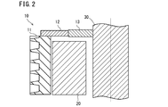
- FIG. 2 is a cross-sectional view of the eddy current type reduction device shown in FIG. 1 in the axial direction of the propeller shaft when the eddy current type reduction device is fixed to the propeller shaft.
- FIG. 3 is a cross-sectional view (diameter cross-sectional view) perpendicular to the axial direction of the eddy current type speed reducer during non-braking.
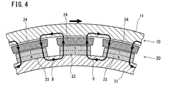
- FIG. 4 is a cross-sectional view (diameter cross-sectional view) perpendicular to the axial direction of the eddy current type speed reducer during braking.
- the present inventors have investigated means for a rotor for an eddy current type speed reducer, which has low electric resistance and high high temperature strength, and can suppress a decrease in high temperature strength due to the cumulative operating time of the eddy current type speed reducer. And examination.
- the present inventors have a chemical composition of C: 0.05 to 0.15%, Si: 0.10 to 0.40%, Mn: 0.50 to 1.00%, P: 0 in mass%. .030% or less, S: 0.030% or less, Mo: 0.20 to 1.00%, Nb: 0.020 to 0.060%, V: 0.040 to 0.080%, sol.
- the tensile strength TS1 (MPa) of the held steel material at 650 ° C. was determined. Then, the difference between the tensile strength TS0 and the tensile strength TS1 is defined as the tensile strength difference ⁇ TS (MPa).
- ⁇ TS tensile strength difference
- the present inventors investigated the mechanism by which the high-temperature strength decreases when the cumulative operating time of the eddy current type speed reducer becomes long.
- quenching and tempering are carried out after hot forging, and the high temperature strength is increased by the dislocation density introduced by quenching.
- high tensile strength can be maintained even at 650 ° C. due to dislocation.
- the cumulative operating time of the eddy current type speed reducer increases, the high temperature holding time of the rotor increases, and the dislocation density in the rotor decreases significantly. Therefore, when the high temperature strength of the rotor for the eddy current type speed reducer is secured by the dislocation density, it is considered that the high temperature strength decreases as the cumulative operating time of the eddy current type speed reducer increases.
- the present inventors suppress a decrease in high-temperature strength due to the cumulative operating time of the eddy current type speed reducer by a mechanism different from the improvement in high-temperature strength by dislocation density in a rotor made of a steel material having the above-mentioned chemical composition. It was investigated.
- Mo carbide (Mo 2 C), cementite, Nb carbide (NbC), V carbide (VC) or the like is present as carbide generating.
- Mo carbide (Mo 2 C), cementite, Nb carbide (NbC), V carbide (VC) or the like is present.
- the finest carbides are Nb carbides and V carbides of MX type precipitates.
- the average circle-equivalent diameter of the MX-type precipitate is 50 nm or less.
- Nb carbide and V carbide are referred to as "fine carbide”.
- Mo carbide and cementite are larger carbides than Nb carbide and V carbide of MX type precipitates, and most of the equivalent circle diameters of Mo carbide and cementite are 100 nm or more.
- Mo carbides and cementites Mo carbides and cementites having a circle-equivalent diameter of 100 to 500 nm are defined as "medium carbides" in this specification.
- Fine carbides and medium carbides increase the high temperature strength of the rotor by the precipitation strengthening mechanism. Therefore, if the present inventors reduce the dislocation density in the rotor more than before and secure the high-temperature strength by precipitation strengthening using fine carbides and medium-sized carbides instead of the dislocation density, the cumulative operating time will accompany. It was thought that the decrease in high temperature strength of the rotor could be suppressed.
- the present inventors examined the high-temperature strength of the rotor in which the number densities of fine carbides and medium-sized carbides were increased.
- the present inventors investigated the cause of this. As a result, the present inventors have found the following matters. If the number density (pieces / ⁇ m 2 ) of medium-sized carbide having a circle equivalent diameter of 100 to 500 nm is too small, the tensile strength TS0 at 650 ° C. becomes too low. Therefore, the number density of medium-sized carbides is required to some extent. However, if the number density of the medium-sized carbide becomes excessively high, many dislocations will be trapped in the medium-sized carbide in the rotor. Therefore, although there are many medium-sized carbides in the rotor, the dislocation density is also excessively high.
- the high temperature strength of the rotor is ensured by the precipitation strengthening mechanism by the fine carbide and the medium carbide and the large number of dislocation densities. Therefore, when this rotor is held at a high temperature for a long time, dislocations in the rotor disappear and the high temperature strength is remarkably lowered.
- the present inventors do not simply increase the number density of medium-sized carbides by utilizing precipitation strengthening in order to suppress the decrease in high-temperature strength after holding at high temperature for a long time. It was considered that there is an appropriate range of the number density of medium-sized carbides that can sufficiently reduce the dislocation density in the rotor while exhibiting the precipitation strengthening mechanism. Therefore, the present inventors are suitable for medium-sized carbides capable of obtaining high high-temperature strength and suppressing a decrease in high-temperature strength after long-term holding at high temperature in a rotor made of a steel material having the above-mentioned chemical composition. The range of number density was examined.
- the number density of carbides (medium-sized carbides) having a circle equivalent diameter of 100 to 500 nm is high.
- the number is 0.35 to 0.75 / ⁇ m 2 , low electrical resistance and high high temperature strength can be obtained, and even after the rotor is held at high temperature for a long time, the decrease in high temperature strength is effectively suppressed. I found out what I could do.
- the rotor for the eddy current type speed reducer of the present embodiment completed based on the above knowledge has the following configuration.
- a rotor for eddy current speed reducers Equipped with a cylindrical part The chemical composition of the cylindrical portion is mass%.
- the rotor for an eddy current type speed reducer according to [1].
- the chemical composition is Cu: 0.01-0.20%, Ni: 0.01 to 0.20% and Cr: Contains one element or two or more elements selected from the group consisting of 0.01 to 0.10%. Rotor for eddy current speed reducer.
- FIG. 1 is a front view of an eddy current type speed reducer to which the rotor for the eddy current type speed reducer of the present embodiment is applied.
- the eddy current speed reducer 1 includes a rotor 10 and a stator 20.
- FIG. 2 is an axial sectional view of the eddy current type speed reducer 1 when the eddy current type speed reducer 1 shown in FIG. 1 is fixed to the propeller shaft 30.
- the rotor 10 is fixed to the propeller shaft 30.
- the stator 20 is fixed to a transmission (not shown).
- the rotor 10 includes a cylindrical portion (drum) 11. More specifically, the rotor 10 includes a cylindrical portion 11, an arm portion 12, and a wheel portion 13.
- the cylindrical portion 11 is cylindrical and has an inner diameter larger than the outer diameter of the stator 20.
- the wheel portion 13 is an annular member having an outer diameter smaller than the inner diameter of the cylindrical portion 11, and has a through hole in the central portion.
- the thickness of the wheel portion 13 (the axial length of the propeller shaft 30) is thinner than the thickness of the cylindrical portion 11 (the axial length of the propeller shaft 30).
- the wheel portion 13 is fixed to the propeller shaft 30 by inserting the propeller shaft 30 into the through hole.
- the arm portion 12 connects the end portion of the cylindrical portion 11 and the wheel portion 13.
- a plurality of cooling fins 11F are formed on the outer peripheral surface of the cylindrical portion 11.
- the cylindrical portion 11, the arm portion 12, and the wheel portion 13 may be integrally formed.
- the cylindrical portion 11, the arm portion 12, and the wheel portion 13 may be composed of separate and independent members.
- FIG. 3 is a cross-sectional view (diameter cross-sectional view) perpendicular to the axial direction of the eddy current type speed reducer 1 during non-braking.
- the stator 20 includes a magnet holding ring 21, a plurality of permanent magnets 22 and 23, and a plurality of pole pieces 24.
- the plurality of permanent magnets 22 and the permanent magnets 23 are alternately arranged in the circumferential direction on the outer peripheral surface of the magnet holding ring 21.
- the surface facing the inner peripheral surface of the cylindrical portion 11 of the rotor 10 is the north pole.
- the surface facing the outer peripheral surface of the magnet holding ring 21 is the S pole.
- the surface facing the inner peripheral surface of the cylindrical portion 11 of the rotor 10 is the S pole.
- the surface facing the outer peripheral surface of the magnet holding ring 21 is the north pole.
- the plurality of pole pieces 24 are arranged above the plurality of permanent magnets 22 and 23, and are arranged in the circumferential direction of the stator 20. The plurality of pole pieces 24 are arranged between the plurality of permanent magnets 22 and 23 and the inner peripheral surface of the cylindrical portion 11.
- FIG. 4 is a cross-sectional view (diameter cross-sectional view) perpendicular to the axial direction of the eddy current type speed reducer 1 during braking.
- the magnet holding ring 21 in the stator 20 rotates to shift the positions of the permanent magnets 22 and 23 relative to the pole piece 24 as compared to FIG.
- each permanent magnet 22 or 23 overlaps with only one pole piece 24 when viewed in the radial direction of the eddy current type speed reducer 1, and two poles.
- the piece 24 does not overlap.
- the magnetic flux B flows between the magnet holding ring 21, the permanent magnet 22 or 23, the pole piece 24, and the cylindrical portion 11.
- a magnetic circuit is formed between the rotor 10 and the permanent magnets 22 or 23. At this time, an eddy current is generated in the cylindrical portion 11 of the rotor 10. Lorentz force is generated with the generation of eddy current. This Lorentz force becomes the braking torque, and the braking force is generated.
- the eddy current type speed reducer 1 generates a braking force by the eddy current generated in the rotor 10. Therefore, it is preferable that the amount of eddy current generated in the cylindrical portion 11 of the rotor 10 is large. This is because the braking force becomes large. The smaller the electrical resistance of the cylindrical portion 11, the larger the amount of eddy current generated. Therefore, it is preferable that the cylindrical portion 11 of the rotor 10 has a small electric resistance.
- the rotor 10 is further loaded with a thermal cycle by repeating braking and non-braking. As described above, recently, it is required to obtain high high-temperature strength even at 650 ° C. Hereinafter, the rotor 10 will be described in detail.
- Carbon (C) enhances the hardenability of the steel material constituting the rotor and enhances the strength of the steel material.
- C further produces fine carbides such as Nb carbides and V carbides to increase the high temperature strength of the steel material.
- C further produces Mo carbide and cementite (medium carbide) having a circle equivalent diameter of 100 to 500 nm to increase the high temperature strength of the steel material. If the C content is less than 0.05%, the above-mentioned effect cannot be sufficiently obtained even if the content of other elements is within the range of the present embodiment.
- the C content is 0.05 to 0.15%.
- the lower limit of the C content is preferably 0.06%, more preferably 0.07%, still more preferably 0.08%.
- the preferred upper limit of the C content is 0.14%, more preferably 0.13%, still more preferably 0.12%.
- Si 0.10 to 0.40%
- Silicon (Si) deoxidizes steel in the steelmaking process. Si further enhances the hardenability of the steel material and enhances the strength of the steel material. If the Si content is less than 0.10%, the above effect cannot be sufficiently obtained even if the content of other elements is within the range of the present embodiment. On the other hand, if the Si content exceeds 0.40%, the electrical resistance of the steel material is excessively increased even if the content of other elements is within the range of the present embodiment. In this case, the amount of eddy current flowing through the cylindrical portion 11 of the rotor 10 is reduced during braking of the eddy current type speed reducer 1. As a result, the braking force of the eddy current type speed reducer 1 is reduced.
- the Si content is 0.10 to 0.40%.
- the lower limit of the Si content is preferably 0.12%, more preferably 0.15%, still more preferably 0.17%.
- the preferred upper limit of the Si content is 0.38%, more preferably 0.36%, still more preferably 0.34%, still more preferably 0.32%, still more preferably 0.30. %, More preferably 0.28%, still more preferably 0.26%.
- Mn 0.50 to 1.00%
- Manganese (Mn) deoxidizes steel in the steelmaking process. Mn further enhances the hardenability of the steel material and enhances the strength of the steel material. If the Mn content is less than 0.50%, the above effect cannot be sufficiently obtained even if the content of other elements is within the range of the present embodiment. On the other hand, if the Mn content exceeds 1.00%, the electrical resistance of the steel material is excessively increased even if the content of other elements is within the range of the present embodiment. In this case, the amount of eddy current flowing through the cylindrical portion 11 of the rotor 10 is reduced during braking of the eddy current type speed reducer 1.
- the Mn content is 0.50 to 1.00%.
- the preferable lower limit of the Mn content is 0.56%, more preferably 0.58%, further preferably 0.60%, still more preferably 0.62%, still more preferably 0.64. %, More preferably 0.66%, still more preferably 0.68%.
- the preferred upper limit of the Mn content is 0.94%, more preferably 0.90%, still more preferably 0.88%.
- Phosphorus (P) is an impurity that is inevitably contained. That is, the P content is more than 0%. P lowers the hot workability and toughness of the steel material. P further increases the electrical resistance of the steel material. In this case, the amount of eddy current flowing through the cylindrical portion 11 of the rotor 10 is reduced during braking of the eddy current type speed reducer 1. As a result, the braking force of the eddy current type speed reducer 1 is reduced. If the P content exceeds 0.030%, the hot workability and toughness of the steel material will be significantly reduced even if the content of other elements is within the range of this embodiment, and further, the eddy current type speed reducer The braking force of 1 is reduced.
- the P content is 0.030% or less.
- the preferred upper limit of the P content is 0.028%, more preferably 0.026%, still more preferably 0.025%. It is preferable that the P content is as low as possible. However, excessive reduction of P content raises manufacturing costs. Therefore, when considering normal industrial production, the preferable lower limit of the P content is 0.001%, more preferably 0.003%.
- S 0.030% or less Sulfur (S) is an impurity that is inevitably contained. That is, the S content is more than 0%. S lowers the hot workability and toughness of the steel material. If the S content exceeds 0.030%, the hot workability and toughness of the steel material will be significantly reduced even if the content of other elements is within the range of the present embodiment. Therefore, the S content is 0.030% or less.
- the preferred upper limit of the S content is 0.025%, more preferably 0.022%, still more preferably 0.020%. It is preferable that the S content is as low as possible. However, excessive reduction of S content raises manufacturing costs. Therefore, when considering normal industrial production, the preferable lower limit of the S content is 0.001%, and more preferably 0.002%.
- Mo 0.20 to 1.00% Molybdenum (Mo) combines with C to form Mo carbide (Mo 2 C).
- Mo further enhances the hardenability of steel materials.
- Mo further enhances the toughness of the steel material. If the Mo content is less than 0.20%, the above effect cannot be sufficiently obtained even if the content of other elements is within the range of the present embodiment. On the other hand, if the Mo content exceeds 1.00%, the electrical resistance of the steel material is excessively increased even if the content of other elements is within the range of the present embodiment.
- the Mo content is 0.20 to 1.00%.
- the lower limit of the Mo content is preferably 0.25%, more preferably 0.30%, still more preferably 0.35%, still more preferably 0.40%.
- the preferred upper limit of the Mo content is 0.90%, more preferably 0.80%, still more preferably 0.70%, still more preferably 0.60%.
- Niobium combines with carbon to form Nb carbides (fine carbides), and the precipitation strengthening enhances the high-temperature strength of the steel material. Nb further suppresses the coarsening of crystal grains. If the Nb content is less than 0.020%, the above effect cannot be sufficiently obtained even if the content of other elements is within the range of the present embodiment. On the other hand, if the Nb content exceeds 0.060%, the electrical resistance of the steel material is excessively increased even if the content of other elements is within the range of the present embodiment. In this case, the amount of eddy current flowing through the cylindrical portion 11 of the rotor 10 is reduced during braking of the eddy current type speed reducer 1.
- the braking force of the eddy current type speed reducer 1 is reduced. If the Nb content exceeds 0.060%, the toughness of the steel material is further reduced. Therefore, the Nb content is 0.020 to 0.060%.
- the preferable lower limit of the Nb content is 0.025%, more preferably 0.030%, still more preferably 0.032%, still more preferably 0.034%.
- the preferred upper limit of the Nb content is 0.058%, more preferably 0.056%, still more preferably 0.054%, still more preferably 0.052%.
- V 0.040 to 0.080% Vanadium (V) combines with carbon to form V carbides (fine carbides), and the precipitation strengthening enhances the high-temperature strength of the steel material. V further suppresses the coarsening of crystal grains. If the V content is less than 0.040%, the above effect cannot be sufficiently obtained even if the content of other elements is within the range of the present embodiment. On the other hand, if the V content exceeds 0.080%, the electrical resistance of the steel material is excessively increased even if the content of other elements is within the range of the present embodiment. In this case, the amount of eddy current flowing through the cylindrical portion 11 of the rotor 10 is reduced during braking of the eddy current type speed reducer 1.
- the braking force of the eddy current type speed reducer 1 is reduced. If the V content exceeds 0.080%, the toughness of the steel material is further reduced. Therefore, the V content is 0.040 to 0.080%.
- the preferred lower limit of the V content is 0.044%, more preferably 0.048%, still more preferably 0.050%.
- the preferred upper limit of the V content is 0.075%, more preferably 0.070%, still more preferably 0.068%, even more preferably 0.066%, still more preferably 0.064. %, More preferably 0.062%.
- sol. Al 0.030 to 0.100%
- Aluminum (Al) deoxidizes steel in the steelmaking process. Al further combines with nitrogen (N) to form AlN, and the crystal grains of the steel material are refined. sol. If the Al content is less than 0.030%, the above effect cannot be sufficiently obtained even if the other element content is within the range of the present embodiment. On the other hand, sol. If the Al content exceeds 0.100%, the electrical resistance of the steel material will be excessively increased even if the content of other elements is within the range of the present embodiment. In this case, the amount of eddy current flowing through the cylindrical portion 11 of the rotor 10 is reduced during braking of the eddy current type speed reducer 1.
- the Al content is 0.030 to 0.100%. sol.
- the lower limit of the Al content is preferably 0.040%, more preferably 0.050%, still more preferably 0.052%. sol.
- the preferred upper limit of the Al content is 0.090%, more preferably 0.088%, further preferably 0.086%, still more preferably 0.084%, still more preferably 0.082. %, More preferably 0.080%.
- B 0.0005 to 0.0050% Boron (B) enhances the hardenability of the steel material and enhances the high temperature strength of the steel material. If the B content is less than 0.0005%, the above effect cannot be sufficiently obtained even if the content of other elements is within the range of the present embodiment. On the other hand, if the B content exceeds 0.0050%, the toughness of the steel material decreases even if the content of other elements is within the range of the present embodiment. Therefore, the B content is 0.0005 to 0.0050%.
- the preferable lower limit of the B content is 0.0008%, more preferably 0.0010%, further preferably 0.0012%, still more preferably 0.0014%, still more preferably 0.0015. %.
- the preferred upper limit of the B content is 0.0045%, more preferably 0.0040%, still more preferably 0.0035%, still more preferably 0.0030%.
- N 0.003 to 0.010%
- Nitrogen (N) combines with Al to form AlN.
- AlN enhances the high temperature strength of the steel material by precipitation strengthening. AlN further refines the crystal grains of the steel material. If the N content is less than 0.003%, the above effect cannot be sufficiently obtained even if the content of other elements is within the range of the present embodiment. On the other hand, if the N content exceeds 0.010%, the electrical resistance of the steel material is excessively increased even if the content of other elements is within the range of the present embodiment. In this case, the amount of eddy current flowing through the cylindrical portion 11 of the rotor 10 is reduced during braking of the eddy current type speed reducer 1.
- the N content is 0.003 to 0.010%.
- the preferable lower limit of the N content is 0.004%.
- the preferred upper limit of the N content is 0.009%, more preferably 0.008%, still more preferably 0.007%, still more preferably 0.006%.
- the balance of the chemical composition of the cylindrical portion 11 of the rotor 10 of the eddy current type speed reducer 1 of the present embodiment is composed of Fe and impurities.
- the impurities are those mixed from ore, scrap, manufacturing environment, etc. as a raw material when the cylindrical portion 11 of the rotor 10 of the present embodiment is industrially manufactured, and the impurities of the present embodiment. It means that it is allowed within a range that does not adversely affect the cylindrical portion 11 of the rotor 10.
- the chemical composition of the cylindrical portion 11 of the rotor 10 of the eddy current type speed reducer 1 of the present embodiment further comprises one element or two or more elements selected from the group consisting of Cu, Ni and Cr instead of a part of Fe. It may be contained. All of these elements are optional elements and enhance the hardenability of steel materials.
- Cu 0 to 0.20%
- Copper (Cu) is an optional element and may not be contained. That is, the Cu content may be 0%. When contained, Cu enhances the hardenability of the steel material and enhances the high temperature strength of the steel material. If even a small amount of Cu is contained, the above effect can be obtained to some extent. However, if the Cu content exceeds 0.20%, the electrical resistance of the steel material will be excessively increased even if the content of other elements is within the range of this embodiment. In this case, the amount of eddy current flowing through the cylindrical portion 11 of the rotor 10 of the eddy current type speed reducer 1 is reduced during braking of the eddy current type speed reducer.
- the Cu content is 0 to 0.20%.
- the lower limit of the Cu content is more than 0%, more preferably 0.01%, still more preferably 0.02%.
- the preferred upper limit of the Cu content is 0.15%, more preferably 0.12%, still more preferably 0.10%.
- Nickel (Ni) is an optional element and may not be contained. That is, the Ni content may be 0%. When contained, Ni enhances the hardenability of the steel material and enhances the high temperature strength of the steel material. If even a small amount of Ni is contained, the above effect can be obtained to some extent. However, if the Ni content exceeds 0.20%, the electrical resistance of the steel material will be excessively increased even if the content of other elements is within the range of the present embodiment. In this case, the amount of eddy current flowing through the cylindrical portion 11 of the rotor 10 of the eddy current type speed reducer 1 is reduced during braking of the eddy current type speed reducer 1.
- the Ni content is 0 to 0.20%.
- the lower limit of the Ni content is more than 0%, more preferably 0.01%, still more preferably 0.02%, still more preferably 0.03%.
- the preferred upper limit of the Ni content is 0.15%, more preferably 0.12%, still more preferably 0.10%.
- Chromium (Cr) is an optional element and may not be contained. That is, the Cr content may be 0%. When contained, Cr enhances the hardenability of the steel material and enhances the high temperature strength of the steel material. If even a small amount of Cr is contained, the above effect can be obtained to some extent. However, if the Cr content exceeds 0.10%, the electrical resistance of the steel material will be excessively increased even if the content of other elements is within the range of the present embodiment. In this case, the amount of eddy current flowing through the cylindrical portion 11 of the rotor 10 of the eddy current type reduction device 1 is reduced during braking of the eddy current type reduction device 1.
- the Cr content is 0 to 0.10%.
- the lower limit of the Cr content is preferably more than 0%, more preferably 0.01%, still more preferably 0.02%.
- the preferred upper limit of the Ni content is 0.09%, more preferably 0.08%, further preferably 0.07%, still more preferably 0.06%, still more preferably 0.05. %.
- the total area ratio of martensite and bainite is more than 95.0%. That is, the microstructure of the cylindrical portion 11 of the rotor 10 for the eddy current type speed reducer of the present embodiment is mainly composed of martensite and / or bainite. As used herein, "martensite and bainite” also include tempered martensite and tempered bainite. In the microstructure of the cylindrical portion 11 of the rotor 10 of the present embodiment, the rest other than martensite and bainite is ferrite. That is, the area ratio of ferrite is less than 5.0%.
- the microstructure of the cylindrical portion 11 also contains precipitates typified by the above-mentioned carbides and inclusions.
- the total area ratio of these precipitates and inclusions is extremely small compared to the area ratio of martensite, bainite and ferrite and can be ignored.
- the microstructure of the cylindrical portion 11 of the rotor 10 for the eddy current type speed reducer of the present embodiment also affects the strength.
- the total area ratio of martensite and bainite is 95.0% or less, and the area ratio of ferrite is 5.0% or more.
- the number density of medium-sized carbides is 0.35 to 0.75 / ⁇ m 2 , sufficient high-temperature strength cannot be obtained.
- the content of each element in the chemical composition is within the range of the present embodiment. Assuming that the number density of medium-sized carbides is 0.35 to 0.75 pieces / ⁇ m 2 , high high-temperature strength can be obtained at 650 ° C.
- the total area ratio of martensite and bainite in the microstructure and the area ratio of ferrite can be measured by the following methods.
- a sample is taken from the center position of the wall thickness of the cylindrical portion 11 of the rotor 10.
- the size of the sample is not particularly limited as long as the observation field of view (200 ⁇ m ⁇ 100 ⁇ m) described later can be secured.
- the observation surface including the observation field of view is mirror-polished.
- the sample after mirror polishing is immersed in a nital solution for about 10 seconds to perform etching to reveal a structure on the observation surface. Any one field of view (observation field of view) in the observation surface where the structure is exposed by etching is observed with a 500x optical microscope.
- the visual field area of the observation field is 20000 ⁇ m 2 (200 ⁇ m ⁇ 100 ⁇ m).
- ferrite and martensite and bainite can be easily distinguished based on the contrast. Therefore, the ferrite in the observation field of view is specified, and the area of the specified ferrite is obtained.
- the area ratio (%) of ferrite is obtained by dividing the area of ferrite by the total area of the observation field of view.
- the number density of carbides (medium-sized carbides) having a circular equivalent diameter of 100 to 500 nm is 0.35 to 0.75 pieces / ⁇ m 2 .
- the content of each element in the chemical composition is within the range of this embodiment, and the total area ratio of martensite and bainite in the microstructure is. Even if it is more than 95.0% and the area ratio of ferrite is less than 5.0%, the number density of medium-sized carbides is too low.
- the number density of medium-sized carbides exceeds 0.75 / ⁇ m 2 , the content of each element in the chemical composition is within the range of this embodiment, and the total area ratio of martensite and bainite in the microstructure. Is more than 95.0% and the area ratio of ferrite is less than 5.0%, the number density of medium-sized carbides is too high. In this case, a large number of dislocations are trapped in the medium-sized carbide, and the dislocation density is also excessively high. Therefore, although high high-temperature strength can be obtained, the decrease in high-temperature strength with the cumulative operating time of the eddy current type speed reducer becomes large.
- the content of each element in the chemical composition is within the range of this embodiment, and the total area of martensite and bainite in the microstructure. Assuming that the ratio is more than 95.0% and the area ratio of ferrite is less than 5.0%, the rotor of the present embodiment has high high temperature strength and the cumulative operating time of the eddy current type speed reducer. It is possible to sufficiently suppress the decrease in high temperature strength due to the above. Specifically, the tensile strength TS0 at 650 ° C. is 250 MPa or more, and the tensile strength difference ⁇ TS at 650 ° C. before and after the high temperature holding test is less than 50 MPa.
- the equivalent circle diameter of the fine carbide is as fine as 50 nm or less, and it is difficult to quantitatively measure the number density. Furthermore, even if the cumulative operating time in the high temperature region becomes long, the shape of the fine carbide does not change very much. Therefore, the fine carbides do not have much effect on the suppression of the decrease in high temperature strength with the cumulative operating time.
- the preferable lower limit of the number density of medium-sized carbides is 0.38 pieces / ⁇ m 2 , more preferably 0.40 pieces / ⁇ m 2 , still more preferably 0.42 pieces / ⁇ m 2 , and further preferably 0. It is 44 pieces / ⁇ m 2 , more preferably 0.46 pieces / ⁇ m 2 , and further preferably 0.48 pieces / ⁇ m 2 .
- the preferred upper limit of the number density of medium-sized carbides is 0.70 pieces / ⁇ m 2 , more preferably 0.68 pieces / ⁇ m 2 , still more preferably 0.66 pieces / ⁇ m 2 , and even more preferably 0. It is 64 pieces / ⁇ m 2 , and more preferably 0.62 pieces / ⁇ m 2 .
- the number density of medium-sized carbides can be measured by the following method.
- a sample is taken from the center position of the wall thickness of the cylindrical portion 11 of the rotor 10.
- the surface corresponding to the cross section perpendicular to the central axis direction of the cylindrical portion 11 is used as the observation surface.
- the observation surface of the sample is mirror-polished.
- the observation surface after mirror polishing is etched with a nital solution.
- Arbitrary 5 visual fields (visual field area of 12 ⁇ m ⁇ 9 ⁇ m per visual field) are observed at a magnification of 10000 times on the observation surface after etching using a scanning electron microscope (SEM).
- the circle-equivalent diameter of each precipitate confirmed in 5 fields of view is determined.
- the equivalent circle diameter can be obtained by well-known image processing.
- those having a circle-equivalent diameter of 100 to 500 nm can be regarded as Mo carbide and / or cementite in the steel material having the chemical composition of the present embodiment. Therefore, a precipitate having a circle-equivalent diameter of 100 to 500 nm is recognized as a medium-sized carbide.
- the number of identified middle- carbides (carbides equivalent circle diameter of 100 ⁇ 500 nm), based on the total area of the five visual fields (540 ⁇ m 2), determine the number density of medium-sized carbide (number / ⁇ m 2).
- the electrical resistance of the cylindrical portion 11 of the rotor 10 can be determined by a measuring method based on JIS C 2526 (1994). Specifically, a test piece including the center position of the wall thickness of the cylindrical portion 11 of the rotor 10 is collected. The test piece shall be a standard test piece of 3 mm ⁇ 4 mm ⁇ 60 mm. At room temperature (20 ⁇ 15 ° C.), the electrical resistance ( ⁇ cm) of the test piece is determined by the double bridge method.
- the tensile strength (MPa) of the cylindrical portion of the rotor for an eddy current type speed reducer at 650 ° C. can be determined by a measuring method based on JIS G 0567 (2012). Specifically, a tensile test piece is collected from the center position of the wall thickness of the cylindrical portion 11 of the rotor 10. The length of the parallel portion of the tensile test piece is 40 mm, the diameter of the parallel portion is 6 mm, and the parallel portion is parallel to the central axis of the cylindrical portion 11. The tensile test piece is heated using a heating furnace to bring the temperature of the tensile test piece to 650 ° C.
- the holding time at 650 ° C. is 10 minutes.
- a tensile test is performed on a tensile test piece at 650 ° C. in the air to obtain a stress-strain curve.
- the tensile strength TS0 (MPa) is obtained from the obtained stress-strain curve.
- the tensile strength difference ⁇ TS can be obtained in the following directions. Specifically, the above-mentioned tensile test piece is collected from the center position of the wall thickness of the cylindrical portion 11 of the rotor 10 in the same manner as the above-mentioned method for measuring the tensile strength at 650 ° C. A high temperature holding test is carried out using the collected tensile test pieces. Specifically, the tensile test piece is held at 650 ° C. for 300 hours using a heating furnace. A tensile test is carried out in the air on a tensile test piece at 650 ° C.
- ⁇ TS TS0-TS1
- each element in the chemical composition is within the range of the above-mentioned embodiment, and the total amount of martensite and bainite in the microstructure is The area ratio is more than 95.0%, and the number density of carbides (medium-sized carbides) having a circle equivalent diameter of 100 to 500 nm is 0.35 to 0.75 pieces / ⁇ m 2 . Therefore, the rotor 10 for the eddy current type speed reducer of the present embodiment has low electric resistance and high high temperature strength, and can sufficiently suppress a decrease in high temperature strength due to the cumulative operating time of the eddy current type speed reducer. ..
- the electrical resistance is 20.0 ⁇ cm or less
- the tensile strength TS0 at 650 ° C. is 250 MPa or more
- the tensile strength difference ⁇ TS at 650 ° C. before and after the above-mentioned high temperature holding test is 50 MPa or less.
- the method for manufacturing the rotor 10 for the eddy current speed reducer of the present embodiment includes a material preparation step for preparing the material of the cylindrical portion 11 of the rotor 10 for the vortex current speed reducer, hot forging and hot forging on the prepared material.
- a hot forging and hot rolling process for producing an intermediate product corresponding to the cylindrical portion 11 by performing hot rolling, a tempering process for performing quenching and tempering treatment for the intermediate product, and an intermediate product.
- each step will be described.
- a material having a chemical composition in which the content of each element is within the range of the present embodiment is prepared.
- the material may be supplied by a third party.
- the material may be manufactured. When manufacturing, for example, it is manufactured by the following method.
- molten steel having a chemical composition in which the content of each element is within the range of this embodiment is not particularly limited, and a well-known method may be used.
- refining primary refining
- secondary refining is carried out on the molten steel discharged from the converter.
- the alloying elements for adjusting the components are added to produce molten steel having a chemical composition in which the content of each element is within the range of the present embodiment.
- the material is produced by a well-known casting method.
- an ingot is manufactured by an ingot method using molten steel.
- bloom or billet may be produced by a continuous casting method using molten steel. After heating the produced bloom or ingot to 1000 to 1300 ° C., hot working may be performed to produce a billet. Hot working is, for example, hot rolling, hot forging and the like.
- the manufactured billet (a billet manufactured by continuous casting or a billet manufactured by hot-working a bloom or an ingot) is used as a material for the rotor 10 for an eddy current type reduction gear.
- Hot forging and hot rolling process are performed on the material prepared in the material preparation step to produce an intermediate product corresponding to the cylindrical portion 11. First, the material is heated to 1000-1300 ° C. The material after heating is hot forged and molded to a predetermined size. After hot forging, hot rolling is further carried out to produce a cylindrical intermediate product.
- a tempering process is carried out on the intermediate products produced by the hot forging and hot rolling processes. Specifically, the intermediate product is subjected to quenching treatment and then tempering treatment.
- the intermediate product is subjected to quenching treatment.
- the quenching temperature is 860 to 930 ° C. If the quenching temperature is less than 860 ° C., the Mo carbides and cementite produced by the hot forging step will not be sufficiently solid-solved. In this case, in the tempering treatment of the next step, the unsolidified Mo carbides and cementite remaining in the intermediate product after the quenching treatment are coarsened. As a result, the number density of medium-sized carbides decreases. Further, if the quenching temperature is less than 860 ° C., the microstructure of the intermediate product held at the quenching temperature does not become austenite single phase.
- the upper limit of the tempering temperature is not particularly limited, but is, for example, 930 ° C. Therefore, the quenching temperature is 860 to 930 ° C.
- the preferred lower limit of the quenching temperature is 865 ° C, more preferably 870 ° C. If the quenching temperature is too high, the austenite will be coarse. Therefore, the preferred upper limit of the quenching temperature is 920 ° C, more preferably 910 ° C.
- the holding time at the above quenching temperature in the quenching treatment is not particularly limited, but is, for example, 1.0 to 2.0 hours.
- Tempering is performed on the intermediate product after quenching.
- the tempering process produces fine carbides and medium carbides.
- the tempering temperature T is 660 to 700 ° C. If the tempering temperature T is less than 660 ° C., the number density of medium-sized carbides is less than 0.35 / ⁇ m 2 . In this case, since the amount of fine carbide and medium carbide precipitated is not sufficient, the high temperature strength becomes low. On the other hand, if the tempering temperature T exceeds 700 ° C., the medium-sized carbides become coarse and the number density of the medium-sized carbides becomes less than 0.35 pieces / ⁇ m 2 . Therefore, the high temperature strength becomes low. In addition, some of the microstructure may transform into austenite. Therefore, the tempering temperature T is 660 to 700 ° C.
- the preferred lower limit of the tempering temperature T is 670 ° C, more preferably 680 ° C.
- the tempering process further satisfies the following equation. 1400 ⁇ (T + 273.15) ⁇ (1 + log (t)) + (Mo / 96 + C / 12) ⁇ 20000 ⁇ 1800 (1)
- T ° C.
- time time
- the content (mass%) of the corresponding element is substituted for the element symbol in the formula (1).
- F1 (T + 273.15) ⁇ (1 + log (t)) + (Mo / 96 + C / 12) ⁇ 20000.
- F1 is an index of the amount of medium-sized carbide precipitated. If F1 is less than 1400, even if the tempering temperature is 660 to 700 ° C., medium-sized carbides are not sufficiently produced, and the number density of medium-sized carbides is less than 0.35 pieces / ⁇ m 2 . On the other hand, if F1 exceeds 1800, even if the tempering temperature is 660 to 700 ° C., the amount of medium-sized carbides produced becomes excessively large, and the number density of medium-sized carbides exceeds 0.75 / ⁇ m 2. It ends up. As a result, the high temperature intensity is significantly reduced with the cumulative operating time of the eddy current type speed reducer.
- F1 is 1400 to 1800, the number density of medium-sized carbides is 0.35 to 0.75 / ⁇ m 2 . Therefore, excellent high-temperature strength can be obtained, and a significant decrease in high-temperature strength due to the cumulative operating time of the eddy current type speed reducer can be sufficiently suppressed.
- the preferred lower limit of F1 is 1410, more preferably 1420.
- the preferred upper limit of F1 is 1790, more preferably 1780, and even more preferably 1770.
- the cooling fins 11F are formed by machining the outer peripheral surface of the intermediate product after tempering. Machining only needs to be done by a well-known method.
- the cylindrical portion 11 is manufactured by the above steps.
- the arm portion 12 attached to the wheel portion 13 is attached to the manufactured cylindrical portion 11 to manufacture the rotor 10 for the eddy current type speed reducer.
- the mounting method may be welding or another method.
- the rotor 10 for the eddy current type speed reducer of the present embodiment can be manufactured.
- the rotor 10 for an eddy current type speed reducer of the present embodiment is not limited to the above manufacturing method, and if the rotor 10 for an eddy current type speed reducer having the above configuration can be manufactured, a manufacturing method other than the above manufacturing method can be used.
- the rotor 10 for the eddy current type speed reducer of the present embodiment may be manufactured.
- the above manufacturing method is a suitable example for manufacturing the rotor 10 for the eddy current type speed reducer of the present embodiment.
- a molten steel having the chemical composition shown in Table 1 was manufactured.
- the blank part in Table 1 means that the content of the corresponding element was below the detection limit.
- the Cu content of test number 1 means that the value rounded to the third decimal place was 0%.
- the Ni content of Test No. 1 means that the value rounded to the first decimal place was 0%.
- the Cr content of Test No. 1 means that the value rounded to the first decimal place was 0%.
- a columnar ingot having a diameter of 120 mm and a diameter of 30 kg was produced by an ingot method using molten steel.
- a sample was taken from the center position of the thickness of the pseudo rotor of each test number. After the surface of the sample was mirror-polished, it was immersed in a nital solution for about 10 seconds to perform etching to reveal the structure. Any one field of view (observation field of view) on the surface where the structure was exposed by etching was observed with a 500x optical microscope. The visual field area of the observation field was 20000 ⁇ m 2 (200 ⁇ m ⁇ 100 ⁇ m). The phase in the observation field was identified by the contrast. As a result, the microstructure in the observation field consisted of martensite, bainite, and ferrite. The area of the identified ferrite was determined.
- the area of ferrite was divided by the total area of the observation field to obtain the area ratio (%) of ferrite.
- the rest other than ferrite was martensite and / or bainite. Therefore, the total area (%) of martensite and bainite was calculated by the following formula.
- Total area ratio of martensite and bainite 100.0-Area ratio of ferrite
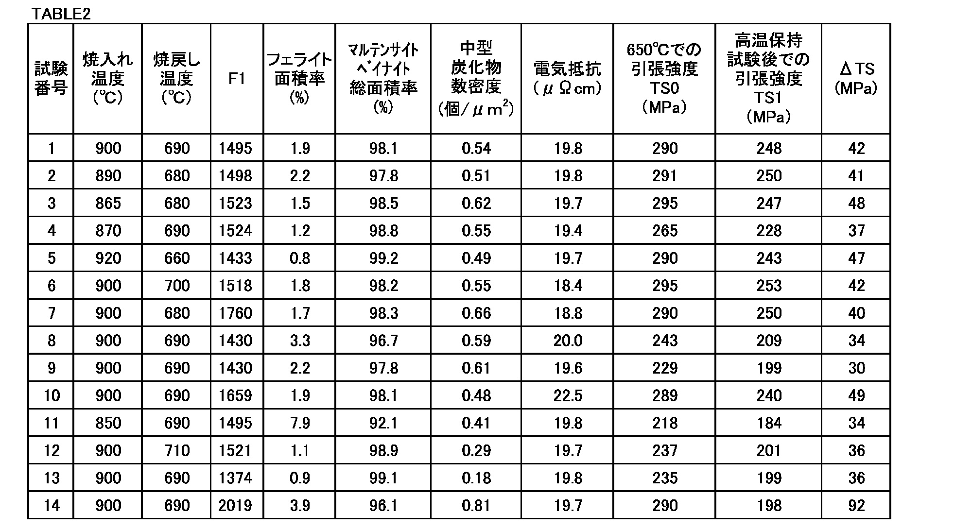
- Table 2 shows the total area ratio (%) of martensite and bainite.
- the precipitate having a circle-equivalent diameter of 100 to 500 nm can be regarded as Mo carbide and / or cementite, so the precipitate having a circle-equivalent diameter of 100 to 500 nm was recognized as a medium-sized carbide.
- the number of medium-sized carbide (circle equivalent diameter of 100 ⁇ 500 nm carbide), based on the total area of the five visual fields (540Myuemu 2), was calculated by determining the number density of the medium-sized carbide (pieces / [mu] m 2). The number densities of the obtained medium-sized carbides are shown in Table 2.
- the electrical resistance of the pseudo rotors of each test number at room temperature was determined by a measuring method based on JIS C 2526 (1994). Specifically, test pieces were collected from the center position of the thickness of the pseudo rotor of each test number. The size of the test piece was 3 mm ⁇ 4 mm ⁇ 60 mm. The electrical resistance ( ⁇ cm) of the test piece was determined by the double bridge method at room temperature. The obtained electrical resistance ( ⁇ cm) is shown in Table 2.
- the tensile strength TS0 (MPa) of the pseudo rotor of each test number at 650 ° C. was determined by a measuring method based on JIS G 0567 (2012). Specifically, a tensile test piece was collected from the center position of the plate thickness of the pseudo rotor of each test number. The length of the parallel portion of the tensile test piece was 40 mm, and the diameter of the parallel portion was 6 mm. The parallel portion of the tensile test piece was parallel to the rolling direction of the pseudo rotor (steel plate). The tensile test piece was heated using a heating furnace to bring the temperature of the test piece to 650 ° C. The holding time at 650 ° C.
- the tensile strength difference ⁇ TS of the pseudo rotor of each test number was determined in the following directions. Similar to the above-mentioned tensile test at 650 ° C., a test piece was taken from the center position of the plate thickness of the pseudo rotor. The length of the parallel portion of the tensile test piece was 40 mm, and the diameter of the parallel portion was 6 mm. The parallel portion of the tensile test piece was parallel to the rolling direction of the pseudo rotor (steel plate). The tensile test piece was held at 650 ° C. for 300 hours using a heating furnace.
- the Mo content and B content were too low. Therefore, the tensile strength TS0 at 650 ° C. was less than 250 MPa.
- the C content was too low. Therefore, the tensile strength TS0 at 650 ° C. was less than 250 MPa.
- test number 11 the content of each element was appropriate, but the quenching temperature was too low. Therefore, the total area ratio of martensite and bainite was 95.0% or less. As a result, the tensile strength TS0 at 650 ° C. was less than 250 MPa.
- the content of each element was appropriate, but the tempering temperature was too high. Therefore, the medium-sized carbide number density was less than 0.35 / ⁇ m 2 . As a result, the tensile strength TS0 at 650 ° C. was less than 250 MPa.
- the F1 value was less than the lower limit of the formula (1). Therefore, the medium-sized carbide number density was less than 0.35 / ⁇ m 2 . As a result, the tensile strength TS0 at 650 ° C. was less than 250 MPa.
Landscapes
- Chemical & Material Sciences (AREA)
- Engineering & Computer Science (AREA)
- Materials Engineering (AREA)
- Mechanical Engineering (AREA)
- Metallurgy (AREA)
- Organic Chemistry (AREA)
- Power Engineering (AREA)
- Physics & Mathematics (AREA)
- Thermal Sciences (AREA)
- Crystallography & Structural Chemistry (AREA)
- Dynamo-Electric Clutches, Dynamo-Electric Brakes (AREA)
- Heat Treatment Of Steel (AREA)
- Heat Treatment Of Articles (AREA)
Abstract
Description
円筒部を備え、
前記円筒部の化学組成が、質量%で、
C:0.05~0.15%、
Si:0.10~0.40%、
Mn:0.50~1.00%、
P:0.030%以下、
S:0.030%以下、
Mo:0.20~1.00%、
Nb:0.020~0.060%、
V:0.040~0.080%、
sol.Al:0.030~0.100%、
B:0.0005~0.0050%、
N:0.003~0.010%、
Cu:0~0.20%、
Ni:0~0.20%、
Cr:0~0.10%、及び、
残部:Fe及び不純物、からなり、
ミクロ組織におけるマルテンサイト及びベイナイトの総面積率は95.0%超であり、
円相当径が100~500nmの炭化物の数密度が0.35~0.75個/μm2である。
渦電流式減速装置用ロータであって、
円筒部を備え、
前記円筒部の化学組成が、質量%で、
C:0.05~0.15%、
Si:0.10~0.40%、
Mn:0.50~1.00%、
P:0.030%以下、
S:0.030%以下、
Mo:0.20~1.00%、
Nb:0.020~0.060%、
V:0.040~0.080%、
sol.Al:0.030~0.100%、
B:0.0005~0.0050%、
N:0.003~0.010%、
Cu:0~0.20%、
Ni:0~0.20%、
Cr:0~0.10%、及び、
残部:Fe及び不純物、からなり、
ミクロ組織におけるマルテンサイト及びベイナイトの総面積率は95.0%超であり、
円相当径が100~500nmの炭化物の数密度が0.35~0.75個/μm2である、
渦電流式減速装置用ロータ。
[1]に記載の渦電流式減速装置用ロータであって、
前記化学組成は、
Cu:0.01~0.20%、
Ni:0.01~0.20%、及び、
Cr:0.01~0.10%、からなる群から選択される1元素又は2元素以上を含有する、
渦電流式減速装置用ロータ。
図1は、本実施形態の渦電流式減速装置用ロータが適用される、渦電流式減速装置の正面図である。図1を参照して、渦電流式減速装置1は、ロータ10と、ステータ20とを備える。
図3を参照して、非制動時において、渦電流式減速装置1の径方向に見た場合、各永久磁石22及び各永久磁石23は、互いに隣り合う2つのポールピース24と重複している。換言すれば、渦電流式減速装置1の径方向に見た場合、1つのポールピース24が、互いに隣り合う永久磁石22及び23と重複している。この場合、磁束Bは図3に示すとおり、ステータ20内を流れる。具体的には、磁束Bは、永久磁石22及び23と、ポールピース24と、磁石保持リング21との間を流れる。そのため、ロータ10と永久磁石22及び23との間には磁気回路が形成されておらず、ロータ10にローレンツ力が発生しない。したがって、図3では、制動力が作動しない。
[化学組成]
本実施形態の渦電流式減速装置用ロータ10の円筒部11の化学組成は、次の元素を含有する。元素に関する「%」は、特に断りがない限り、質量%を意味する。
C:0.05~0.15%
炭素(C)は、ロータを構成する鋼材の焼入れ性を高め、鋼材の強度を高める。Cはさらに、Nb炭化物、V炭化物等の微細炭化物を生成し、鋼材の高温強度を高める。Cはさらに、円相当径が100~500nmのMo炭化物及びセメンタイト(中型炭化物)を生成して、鋼材の高温強度を高める。C含有量が0.05%未満であれば、他の元素含有量が本実施形態の範囲内であっても、上述の効果が十分に得られない。一方、C含有量が0.15%を超えれば、他の元素含有量が本実施形態の範囲内であっても、鋼材の電気抵抗が過剰に高まる。この場合、渦電流式減速装置1の制動時において、ロータ10の円筒部11を流れる渦電流量が減少する。その結果、渦電流式減速装置1の制動力が低下する。したがって、C含有量は0.05~0.15%である。C含有量の好ましい下限は0.06%であり、さらに好ましくは0.07%であり、さらに好ましくは0.08%である。C含有量の好ましい上限は0.14%であり、さらに好ましくは0.13%であり、さらに好ましくは0.12%である。
シリコン(Si)は、製鋼工程において、鋼を脱酸する。Siはさらに、鋼材の焼入れ性を高め、鋼材の強度を高める。Si含有量が0.10%未満であれば、他の元素含有量が本実施形態の範囲内であっても、上記効果が十分に得られない。一方、Si含有量が0.40%を超えれば、他の元素含有量が本実施形態の範囲内であっても、鋼材の電気抵抗が過剰に高まる。この場合、渦電流式減速装置1の制動時において、ロータ10の円筒部11を流れる渦電流量が減少する。その結果、渦電流式減速装置1の制動力が低下する。したがって、Si含有量は0.10~0.40%である。Si含有量の好ましい下限は0.12%であり、さらに好ましくは0.15%であり、さらに好ましくは0.17%である。Si含有量の好ましい上限は0.38%であり、さらに好ましくは0.36%であり、さらに好ましくは0.34%であり、さらに好ましくは0.32%であり、さらに好ましくは0.30%であり、さらに好ましくは0.28%であり、さらに好ましくは0.26%である。
マンガン(Mn)は、製鋼工程において、鋼を脱酸する。Mnはさらに、鋼材の焼入れ性を高め、鋼材の強度を高める。Mn含有量が0.50%未満であれば、他の元素含有量が本実施形態の範囲内であっても、上記効果が十分に得られない。一方、Mn含有量が1.00%を超えれば、他の元素含有量が本実施形態の範囲内であっても、鋼材の電気抵抗が過剰に高まる。この場合、渦電流式減速装置1の制動時において、ロータ10の円筒部11を流れる渦電流量が減少する。その結果、渦電流式減速装置1の制動力が低下する。したがって、Mn含有量は0.50~1.00%である。Mn含有量の好ましい下限は0.56%であり、さらに好ましくは0.58%であり、さらに好ましくは0.60%であり、さらに好ましくは0.62%であり、さらに好ましくは0.64%であり、さらに好ましくは0.66%であり、さらに好ましくは0.68%である。Mn含有量の好ましい上限は0.94%であり、さらに好ましくは0.90%であり、さらに好ましくは0.88%である。
燐(P)は不可避に含有される不純物である。つまり、P含有量は0%超である。Pは、鋼材の熱間加工性及び靱性を低下する。Pはさらに、鋼材の電気抵抗を高める。この場合、渦電流式減速装置1の制動時において、ロータ10の円筒部11を流れる渦電流量が減少する。その結果、渦電流式減速装置1の制動力が低下する。P含有量が0.030%を超えれば、他の元素含有量が本実施形態の範囲内であっても、鋼材の熱間加工性及び靱性が顕著に低下し、さらに、渦電流式減速装置1の制動力が低下する。したがって、P含有量は0.030%以下である。P含有量の好ましい上限は0.028%であり、さらに好ましくは0.026%であり、さらに好ましくは0.025%である。P含有量はなるべく低い方が好ましい。しかしながら、P含有量の過剰な低減は、製造コストを引き上げる。したがって、通常の工業生産を考慮した場合、P含有量の好ましい下限は0.001%であり、さらに好ましくは0.003%である。
硫黄(S)は不可避に含有される不純物である。つまり、S含有量は0%超である。Sは、鋼材の熱間加工性及び靱性を低下する。S含有量が0.030%を超えれば、他の元素含有量が本実施形態の範囲内であっても、鋼材の熱間加工性及び靱性が顕著に低下する。したがって、S含有量は0.030%以下である。S含有量の好ましい上限は0.025%であり、さらに好ましくは0.022%であり、さらに好ましくは0.020%である。S含有量はなるべく低い方が好ましい。しかしながら、S含有量の過剰な低減は、製造コストを引き上げる。したがって、通常の工業生産を考慮した場合、S含有量の好ましい下限は0.001%であり、さらに好ましくは0.002%である。
モリブデン(Mo)は、Cと結合してMo炭化物(Mo2C)を形成する。Mo炭化物を含む100~500nmの円相当径の析出物が0.35~0.75個/μm2であることを条件として、鋼材の高温強度が高まる。Moはさらに、鋼材の焼入れ性を高める。Moはさらに、鋼材の靱性を高める。Mo含有量が0.20%未満であれば、他の元素含有量が本実施形態の範囲内であっても、上記効果が十分に得られない。一方、Mo含有量が1.00%を超えれば、他の元素含有量が本実施形態の範囲内であっても、鋼材の電気抵抗が過剰に高まる。この場合、渦電流式減速装置1の制動時において、ロータ10の円筒部11を流れる渦電流量が減少する。その結果、渦電流式減速装置1の制動力が低下する。したがって、Mo含有量は0.20~1.00%である。Mo含有量の好ましい下限は0.25%であり、さらに好ましくは0.30%であり、さらに好ましくは0.35%であり、さらに好ましくは0.40%である。Mo含有量の好ましい上限は0.90%であり、さらに好ましくは0.80%であり、さらに好ましくは0.70%であり、さらに好ましくは0.60%である。
ニオブ(Nb)は、炭素と結合してNb炭化物(微細炭化物)を生成し、析出強化により、鋼材の高温強度を高める。Nbはさらに、結晶粒の粗大化を抑制する。Nb含有量が0.020%未満であれば、他の元素含有量が本実施形態の範囲内であっても、上記効果が十分に得られない。一方、Nb含有量が0.060%を超えれば、他の元素含有量が本実施形態の範囲内であっても、鋼材の電気抵抗が過剰に高まる。この場合、渦電流式減速装置1の制動時において、ロータ10の円筒部11を流れる渦電流量が減少する。その結果、渦電流式減速装置1の制動力が低下する。Nb含有量が0.060%を超えればさらに、鋼材の靱性が低下する。したがって、Nb含有量は0.020~0.060%である。Nb含有量の好ましい下限は0.025%であり、さらに好ましくは0.030%であり、さらに好ましくは0.032%であり、さらに好ましくは0.034%である。Nb含有量の好ましい上限は0.058%であり、さらに好ましくは0.056%であり、さらに好ましくは0.054%であり、さらに好ましくは0.052%である。
バナジウム(V)は、炭素と結合してV炭化物(微細炭化物)を生成し、析出強化により、鋼材の高温強度を高める。Vはさらに、結晶粒の粗大化を抑制する。V含有量が0.040%未満であれば、他の元素含有量が本実施形態の範囲内であっても、上記効果が十分に得られない。一方、V含有量が0.080%を超えれば、他の元素含有量が本実施形態の範囲内であっても、鋼材の電気抵抗が過剰に高まる。この場合、渦電流式減速装置1の制動時において、ロータ10の円筒部11を流れる渦電流量が減少する。その結果、渦電流式減速装置1の制動力が低下する。V含有量が0.080%を超えればさらに、鋼材の靱性が低下する。したがって、V含有量は0.040~0.080%である。V含有量の好ましい下限は0.044%であり、さらに好ましくは0.048%であり、さらに好ましくは0.050%である。V含有量の好ましい上限は0.075%であり、さらに好ましくは0.070%であり、さらに好ましくは0.068%であり、さらに好ましくは0.066%であり、さらに好ましくは0.064%であり、さらに好ましくは0.062%である。
アルミニウム(Al)は、製鋼工程において、鋼を脱酸する。Alはさらに、窒素(N)と結合してAlNを形成し、鋼材の結晶粒を微細化する。sol.Al含有量が0.030%未満であれば、他の元素含有量が本実施形態の範囲内であっても、上記効果が十分に得られない。一方、sol.Al含有量が0.100%を超えれば、他の元素含有量が本実施形態の範囲内であっても、鋼材の電気抵抗が過剰に高まる。この場合、渦電流式減速装置1の制動時において、ロータ10の円筒部11を流れる渦電流量が減少する。その結果、渦電流式減速装置1の制動力が低下する。したがって、sol.Al含有量は0.030~0.100%である。sol.Al含有量の好ましい下限は0.040%であり、さらに好ましくは0.050%であり、さらに好ましくは0.052%である。sol.Al含有量の好ましい上限は0.090%であり、さらに好ましくは0.088%であり、さらに好ましくは0.086%であり、さらに好ましくは0.084%であり、さらに好ましくは0.082%であり、さらに好ましくは0.080%である。
ボロン(B)は鋼材の焼入れ性を高め、鋼材の高温強度を高める。B含有量が0.0005%未満であれば、他の元素含有量が本実施形態の範囲内であっても、上記効果が十分に得られない。一方、B含有量が0.0050%を超えれば、他の元素含有量が本実施形態の範囲内であっても、鋼材の靱性が低下する。したがって、B含有量は0.0005~0.0050%である。B含有量の好ましい下限は0.0008%であり、さらに好ましくは0.0010%であり、さらに好ましくは0.0012%であり、さらに好ましくは0.0014%であり、さらに好ましくは0.0015%である。B含有量の好ましい上限は0.0045%であり、さらに好ましくは0.0040%であり、さらに好ましくは0.0035%であり、さらに好ましくは0.0030%である。
窒素(N)は、Alと結合してAlNを形成する。AlNは、析出強化により、鋼材の高温強度を高める。AlNはさらに、鋼材の結晶粒を微細化する。N含有量が0.003%未満であれば、他の元素含有量が本実施形態の範囲内であっても、上記効果が十分に得られない。一方、N含有量が0.010%を超えれば、他の元素含有量が本実施形態の範囲内であっても、鋼材の電気抵抗が過剰に高まる。この場合、渦電流式減速装置1の制動時において、ロータ10の円筒部11を流れる渦電流量が減少する。その結果、渦電流式減速装置1の制動力が低下する。したがって、N含有量は0.003~0.010%である。N含有量の好ましい下限は0.004%である。N含有量の好ましい上限は0.009%であり、さらに好ましくは0.008%であり、さらに好ましくは0.007%であり、さらに好ましくは0.006%である。
本実施形態の渦電流式減速装置1のロータ10の円筒部11の化学組成はさらに、Feの一部に代えて、Cu、Ni及びCrからなる群から選択される1元素又は2元素以上を含有してもよい。これらの元素はいずれも任意元素であり、鋼材の焼入れ性を高める。
銅(Cu)は任意元素であり、含有されなくてもよい。つまり、Cu含有量は0%であってもよい。含有される場合、Cuは、鋼材の焼入れ性を高め、鋼材の高温強度を高める。Cuが少しでも含有されれば、上記効果はある程度得られる。しかしながら、Cu含有量が0.20%を超えれば、他の元素含有量が本実施形態の範囲内であっても、鋼材の電気抵抗が過剰に高まる。この場合、渦電流式減速装置の制動時において、渦電流式減速装置1のロータ10の円筒部11を流れる渦電流量が減少する。その結果、渦電流式減速装置1の制動力が低下する。したがって、Cu含有量は0~0.20%である。Cu含有量の好ましい下限は0%超であり、さらに好ましくは0.01%であり、さらに好ましくは0.02%である。Cu含有量の好ましい上限は0.15%であり、さらに好ましくは0.12%であり、さらに好ましくは0.10%である。
ニッケル(Ni)は任意元素であり、含有されなくてもよい。つまり、Ni含有量は0%であってもよい。含有される場合、Niは、鋼材の焼入れ性を高め、鋼材の高温強度を高める。Niが少しでも含有されれば、上記効果はある程度得られる。しかしながら、Ni含有量が0.20%を超えれば、他の元素含有量が本実施形態の範囲内であっても、鋼材の電気抵抗が過剰に高まる。この場合、渦電流式減速装置1の制動時において、渦電流式減速装置1のロータ10の円筒部11を流れる渦電流量が減少する。その結果、渦電流式減速装置1の制動力が低下する。したがって、Ni含有量は0~0.20%である。Ni含有量の好ましい下限は0%超であり、さらに好ましくは0.01%であり、さらに好ましくは0.02%であり、さらに好ましくは0.03%である。Ni含有量の好ましい上限は0.15%であり、さらに好ましくは0.12%であり、さらに好ましくは0.10%である。
クロム(Cr)は任意元素であり、含有されなくてもよい。つまり、Cr含有量は0%であってもよい。含有される場合、Crは、鋼材の焼入れ性を高め、鋼材の高温強度を高める。Crが少しでも含有されれば、上記効果はある程度得られる。しかしながら、Cr含有量が0.10%を超えれば、他の元素含有量が本実施形態の範囲内であっても、鋼材の電気抵抗が過剰に高まる。この場合、渦電流式減速装置1の制動時において、渦電流式減速装置1のロータ10の円筒部11を流れる渦電流量が減少する。その結果、渦電流式減速装置1の制動力が低下する。したがって、Cr含有量は0~0.10%である。Cr含有量の好ましい下限は0%超であり、さらに好ましくは0.01%であり、さらに好ましくは0.02%である。Ni含有量の好ましい上限は0.09%であり、さらに好ましくは0.08%であり、さらに好ましくは0.07%であり、さらに好ましくは0.06%であり、さらに好ましくは0.05%である。
本実施形態のロータ10の円筒部11のミクロ組織では、マルテンサイト及びベイナイトの総面積率が95.0%超である。つまり、本実施形態の渦電流式減速装置用ロータ10の円筒部11のミクロ組織は、主としてマルテンサイト及び/又はベイナイトからなる組織である。本明細書でいう「マルテンサイト及びベイナイト」は、焼戻しマルテンサイト及び焼戻しベイナイトも含む。本実施形態のロータ10の円筒部11のミクロ組織において、マルテンサイト及びベイナイト以外の残部はフェライトである。つまり、フェライトの面積率は5.0%未満である。
マルテンサイト及びベイナイトの総面積率=100.0-フェライトの面積率
本実施形態のロータ10の円筒部11ではさらに、円相当径が100~500nmの炭化物(中型炭化物)の数密度が0.35~0.75個/μm2である。中型炭化物の数密度が0.35個/μm2未満であれば、化学組成中の各元素含有量が本実施形態の範囲内であって、ミクロ組織中のマルテンサイト及びベイナイトの総面積率が95.0%超であり、フェライトの面積率が5.0%未満であっても、中型炭化物の数密度が低すぎる。そのため、十分な高温強度が得られない。一方、中型炭化物の数密度が0.75個/μm2を超えれば、化学組成中の各元素含有量が本実施形態の範囲内であって、ミクロ組織中のマルテンサイト及びベイナイトの総面積率が95.0%超であり、フェライトの面積率が5.0%未満であっても、中型炭化物の数密度が高すぎる。この場合、多数の転位が中型炭化物にトラップされてしまい、転位密度も過剰に高くなっている。そのため、高い高温強度は得られるものの、渦電流式減速装置の累積稼働時間に伴う高温強度の低下が大きくなる。
中型炭化物の数密度は、次の方法で測定することができる。ロータ10の円筒部11の肉厚中央位置からサンプルを採取する。サンプルの表面のうち、円筒部11の中心軸方向に垂直な断面に相当する表面を観察面とする。サンプルの観察面を鏡面研磨する。鏡面研磨後の観察面に対して、ナイタル液でエッチングを実施する。エッチング後の観察面に対して、走査型電子顕微鏡(SEM)を用いて、10000倍の倍率で、任意の5視野(1視野あたりの視野面積12μm×9μm)を観察する。
ロータ10の円筒部11の電気抵抗は、JIS C 2526(1994)に準拠した測定方法により求めることができる。具体的には、ロータ10の円筒部11の肉厚中央位置を含む試験片を採取する。試験片は、3mm×4mm×60mmの標準試験片とする。常温(20±15℃)で、ダブルブリッジ法により、試験片の電気抵抗(μΩcm)を求める。
渦電流式減速装置用ロータの円筒部の650℃での引張強度(MPa)は、JIS G 0567(2012)に準拠した測定方法により求めることができる。具体的には、ロータ10の円筒部11の肉厚中央位置から引張試験片を採取する。引張試験片の平行部の長さは40mm、平行部の直径は6mmとし、平行部は、円筒部11の中心軸と平行とする。加熱炉を用いて引張試験片を加熱して、引張試験片の温度を650℃にする。650℃での保持時間は10分とする。650℃の引張試験片に対して、大気中にて引張試験を実施して、応力-ひずみ曲線を得る。得られた応力-ひずみ曲線から引張強度TS0(MPa)を求める。
引張強度差ΔTSは次の方向により求めることができる。具体的には、上述の650℃での引張強度の測定方法と同様に、ロータ10の円筒部11の肉厚中央位置から上述の引張試験片を採取する。採取した引張試験片を用いて、高温保持試験を実施する。具体的には、加熱炉を用いて引張試験片を650℃で300時間保持する。保持時間経過後の650℃の引張試験片に対して、大気中にて引張試験を実施して、応力-ひずみ曲線を得る。得られた応力-ひずみ曲線から引張強度TS1(MPa)を求める。求めた引張強度TS0及びTS1を用いて、次式により、高温保持試験前後の650℃での引張強度差ΔTS(MPa)を求める。
ΔTS=TS0-TS1
本実施形態の渦電流式減速装置用ロータ10の製造方法の一例を説明する。以降に説明する製造方法は、本実施形態の渦電流式減速装置用ロータ10を製造するための一例である。したがって、上述の構成を有する渦電流式減速装置用ロータ10は、以降に説明する製造方法以外の他の製造方法により製造されてもよい。しかしながら、以降に説明する製造方法は、本実施形態の渦電流式減速装置用ロータ10の製造方法の好ましい一例である。
素材準備工程では、各元素含有量が本実施形態の範囲内の化学組成を有する素材を準備する。素材は第三者から供給されたものであってもよい。素材を製造してもよい。製造する場合、たとえば、次の方法で製造する。
素材準備工程にて準備された素材に対して熱間鍛造及び熱間圧延を実施して、円筒部11に相当する中間品を製造する。始めに、素材を1000~1300℃に加熱する。加熱後の素材に対して、熱間鍛造を実施して所定の寸法に成型する。熱間鍛造後さらに、熱間圧延を実施して、円筒状の中間品を製造する。
熱間鍛造及び熱間圧延工程により製造された中間品に対して、調質処理工程を実施する。具体的には、中間品に対して、焼入れ処理を実施した後、焼戻し処理を実施する。
始めに、中間品に対して、焼入れ処理を実施する。焼入れ温度は860~930℃である。焼入れ温度が860℃未満であれば、熱間鍛造工程により生成したMo炭化物及びセメンタイトが十分に固溶しない。この場合、次工程の焼戻し処理において、焼入れ処理後に中間品内に残存する未固溶のMo炭化物及びセメンタイトが粗大化してしまう。その結果、中型炭化物の数密度が低下する。また、焼入れ温度が860℃未満であればさらに、焼入れ温度で保持している中間品のミクロ組織がオーステナイト単相にならない。そのため、焼入れ後処理の組織において、マルテンサイト及び/又はベイナイトだけでなく、フェライトが残存してしまう。焼戻し温度の上限は特に限定されないが、たとえば、930℃である。したがって、焼入れ温度は860~930℃である。焼入れ温度の好ましい下限は865℃であり、さらに好ましくは870℃である。焼入れ温度が高すぎれば、オーステナイトが粗粒になる。そのため、焼入れ温度の好ましい上限は920℃であり、さらに好ましくは910℃である。
焼入れ処理後の中間品に対して、焼戻し処理を実施する。焼戻し処理により、微細炭化物及び中型炭化物を生成する。焼戻し温度Tは660~700℃である。焼戻し温度Tが660℃未満であれば、中型炭化物の数密度が0.35個/μm2未満になる。この場合、微細炭化物及び中型炭化物の析出量が十分ではないため、高温強度が低くなる。一方、焼戻し温度Tが700℃を超えれば、中型炭化物が粗大化してしまい、中型炭化物の数密度が0.35個/μm2未満になる。そのため、高温強度が低くなる。さらに、ミクロ組織の一部がオーステナイトに変態してしまう可能性がある。したがって、焼戻し温度Tは660~700℃である。焼戻し温度Tの好ましい下限は670℃であり、さらに好ましくは680℃である。
1400≦(T+273.15)×(1+log(t))+(Mo/96+C/12)×20000≦1800 (1)
ここで、式(1)中の「T」には焼戻し温度T(℃)が代入され、「t」には焼き戻し保持時間(時間)が代入される。式(1)中の元素記号には、対応する元素の含有量(質量%)が代入される。
焼戻し後の中間品の外周面を機械加工することにより、冷却フィン11Fを形成する。機械加工は周知の方法で実施すれば足りる。以上の工程により、円筒部11が製造される。
製造された円筒部11に、ホイール部13に取り付けられたアーム部12を取り付けて、渦電流式減速装置用ロータ10を製造する。取り付け方法は溶接であってもよいし、他の方法であってもよい。

製造した各試験番号の擬似ロータに対して、次の評価試験を実施した。
マルテンサイト及びベイナイトの総面積率=100.0-フェライトの面積率
求めたフェライトの面積率(%)を、表2に示す。マルテンサイト及びベイナイトの総面積率(%)を表2に示す。
各試験番号の擬似ロータの板厚中央位置からサンプルを採取した。サンプルの観察面を鏡面研磨した。鏡面研磨後の観察面に対して、ナイタル液でエッチングを実施した。エッチング後の観察面に対して、走査型電子顕微鏡(SEM)を用いて、10000倍の倍率でランダムで5視野(1視野あたりの視野面積12μm×9μm)を観察した。5視野で確認された各析出物の円相当径を求めた。各析出物のうち、円相当径が100~500nmの析出物は、Mo炭化物及び/又はセメンタイトとみなすことができるため、円相当径が100~500nmの析出物を、中型炭化物と認定した。中型炭化物(円相当径が100~500nmの炭化物)の個数と、5視野の総面積(540μm2)とに基づいて、中型炭化物の数密度(個/μm2)を求めた。得られた中型炭化物の数密度を表2に示す。
各試験番号の擬似ロータの常温での電気抵抗を、JIS C 2526(1994)に準拠した測定方法により求めた。具体的には、各試験番号の擬似ロータの板厚中央位置から、試験片を採取した。試験片のサイズは3mm×4mm×60mmであった。試験片に対して、常温で、ダブルブリッジ法により、試験片の電気抵抗(μΩcm)を求めた。得られた電気抵抗(μΩcm)を、表2に示す。
各試験番号の擬似ロータの650℃での引張強度TS0(MPa)を、JIS G 0567(2012)に準拠した測定方法により求めた。具体的には、各試験番号の擬似ロータの板厚中央位置から、引張試験片を採取した。引張試験片の平行部の長さは40mm、平行部の直径は6mmであった。引張試験片の平行部は、擬似ロータ(鋼板)の圧延方向と平行であった。加熱炉を用いて引張試験片を加熱して、試験片の温度を650℃にした。650℃での保持時間は10分とした。650℃の引張試験片に対して、大気中にて引張試験を実施して、応力-ひずみ曲線を得た。得られた応力-ひずみ曲線から引張強度TS0(MPa)と定義した。得られた650℃での引張強度TS0(MPa)を、表2に示す。
各試験番号の擬似ロータの引張強度差ΔTSを次の方向により求めた。上述の650℃での引張試験と同様に、擬似ロータの板厚中央位置から試験片を採取した。引張試験片の平行部の長さは40mm、平行部の直径は6mmであった。引張試験片の平行部は、擬似ロータ(鋼板)の圧延方向と平行であった。加熱炉を用いて引張試験片を650℃で300時間保持した。保持時間経過後の650℃の引張試験片に対して、大気中にて引張試験を実施して、応力-ひずみ曲線を得た。得られた応力-ひずみ曲線から引張強度TS1(MPa)を求めた。求めた引張強度TS0及びTS1を用いて、次式により、高温保持試験前後の650℃での引張強度差ΔTSを求めた。得られた引張強度差ΔTSを表2に示す。
ΔTS=TS0-TS1
表2を参照して、試験番号1~7の擬似ロータの化学組成中の各元素の含有量はいずれも適切であり、マルテンサイト及びベイナイトの総面積率が95.0%以上であった。さらに、中型炭化物の数密度が0.35~0.75個/μm2であった。そのため、電気抵抗は20.0μΩcm以下であり、渦電流式減速装置のロータとして、十分に低い電気抵抗を示した。さらに、650℃での引張強度TS0はいずれも250MPa以上であり、優れた高温強度を示した。さらに、引張強度差ΔTSは50MPa以下であり、高温保持試験後の高温強度の低下が十分に抑えられていた。
10 ロータ
11 円筒部
12 アーム部
13 ホイール部
20 ステータ
Claims (2)
- 渦電流式減速装置用ロータであって、
円筒部を備え、
前記円筒部の化学組成が、質量%で、
C:0.05~0.15%、
Si:0.10~0.40%、
Mn:0.50~1.00%、
P:0.030%以下、
S:0.030%以下、
Mo:0.20~1.00%、
Nb:0.020~0.060%、
V:0.040~0.080%、
sol.Al:0.030~0.100%、
B:0.0005~0.0050%、
N:0.003~0.010%、
Cu:0~0.20%、
Ni:0~0.20%、
Cr:0~0.10%、及び、
残部:Fe及び不純物、からなり、
ミクロ組織におけるマルテンサイト及びベイナイトの総面積率は95.0%超であり、
円相当径が100~500nmの炭化物の数密度が0.35~0.75個/μm2である、
渦電流式減速装置用ロータ。 - 請求項1に記載の渦電流式減速装置用ロータであって、
前記化学組成は、
Cu:0.01~0.20%、
Ni:0.01~0.20%、及び、
Cr:0.01~0.10%、からなる群から選択される1元素又は2元素以上を含有する、
渦電流式減速装置用ロータ。
Priority Applications (5)
| Application Number | Priority Date | Filing Date | Title |
|---|---|---|---|
| JP2021516122A JP7260816B2 (ja) | 2019-04-24 | 2020-04-21 | 渦電流式減速装置用ロータ |
| CN202080030416.1A CN113710827B (zh) | 2019-04-24 | 2020-04-21 | 涡电流式减速装置用转子 |
| KR1020217037990A KR102662623B1 (ko) | 2019-04-24 | 2020-04-21 | 와전류식 감속 장치용 로터 |
| EP20795781.2A EP3960893A4 (en) | 2019-04-24 | 2020-04-21 | ROTOR FOR AN EDDY CURRENT TYPE DEACDER |
| US17/594,198 US11979057B2 (en) | 2019-04-24 | 2020-04-21 | Rotor for eddy current deceleration device |
Applications Claiming Priority (2)
| Application Number | Priority Date | Filing Date | Title |
|---|---|---|---|
| JP2019083029 | 2019-04-24 | ||
| JP2019-083029 | 2019-04-24 |
Publications (1)
| Publication Number | Publication Date |
|---|---|
| WO2020218276A1 true WO2020218276A1 (ja) | 2020-10-29 |
Family
ID=72942772
Family Applications (1)
| Application Number | Title | Priority Date | Filing Date |
|---|---|---|---|
| PCT/JP2020/017151 Ceased WO2020218276A1 (ja) | 2019-04-24 | 2020-04-21 | 渦電流式減速装置用ロータ |
Country Status (6)
| Country | Link |
|---|---|
| US (1) | US11979057B2 (ja) |
| EP (1) | EP3960893A4 (ja) |
| JP (1) | JP7260816B2 (ja) |
| KR (1) | KR102662623B1 (ja) |
| CN (1) | CN113710827B (ja) |
| WO (1) | WO2020218276A1 (ja) |
Cited By (2)
| Publication number | Priority date | Publication date | Assignee | Title |
|---|---|---|---|---|
| JP2020180324A (ja) * | 2019-04-24 | 2020-11-05 | 日本製鉄株式会社 | 渦電流式減速装置用ロータ |
| JPWO2024116347A1 (ja) * | 2022-11-30 | 2024-06-06 |
Families Citing this family (1)
| Publication number | Priority date | Publication date | Assignee | Title |
|---|---|---|---|---|
| IT202300001359A1 (it) * | 2023-01-30 | 2024-07-30 | Ciro Tarallo | Sistema di servofreno elettromagnetico per autoveicoli, a repulsione elettomagnetica, ad effetto lorentz |
Citations (4)
| Publication number | Priority date | Publication date | Assignee | Title |
|---|---|---|---|---|
| JPH03247742A (ja) * | 1990-02-23 | 1991-11-05 | Sumitomo Metal Ind Ltd | 渦電流式減速装置用ローター材とその製造法 |
| JPH0849041A (ja) | 1994-08-05 | 1996-02-20 | Sumitomo Metal Ind Ltd | 渦電流式減速装置用ローター材及びその製造方法 |
| JPH09172770A (ja) * | 1995-12-18 | 1997-06-30 | Sumitomo Metal Ind Ltd | 渦電流式減速装置用ローター |
| US6318518B1 (en) * | 1999-08-31 | 2001-11-20 | Sumitomo Metal Industries, Ltd. | Rotor for eddy current retarder |
Family Cites Families (8)
| Publication number | Priority date | Publication date | Assignee | Title |
|---|---|---|---|---|
| US5108699A (en) * | 1988-10-19 | 1992-04-28 | Electric Power Research Institute | Modified 1% CrMoV rotor steel |
| DE60016286T2 (de) * | 1999-10-04 | 2005-12-08 | Mitsubishi Heavy Industries, Ltd. | Niedrig legierter und hitzebeständiger Stahl, Verfahren zur Wärmebehandlung und Turbinenrotor |
| JP3439197B2 (ja) * | 2001-03-06 | 2003-08-25 | 三菱重工業株式会社 | 低合金耐熱鋼及びその熱処理方法並びにタービンロータ |
| PL2907886T3 (pl) * | 2013-02-26 | 2019-04-30 | Nippon Steel & Sumitomo Metal Corp | Blacha stalowa cienka walcowana na gorąco o dużej wytrzymałości mająca maksymalną wytrzymałość na rozciąganie wynoszącą 980 MPa lub więcej oraz mająca doskonałą utwardzalność przy wypalaniu i wiązkość w niskiej temperaturze |
| RU2648104C2 (ru) * | 2013-09-18 | 2018-03-22 | Ниппон Стил Энд Сумитомо Метал Корпорейшн | Горячештампованная деталь и способ ее изготовления |
| WO2016084289A1 (ja) * | 2014-11-28 | 2016-06-02 | Jfeスチール株式会社 | 磁極用熱延鋼板およびその製造方法、ならびに水力発電用リム部材 |
| BR112019010271A2 (pt) * | 2017-01-17 | 2019-09-10 | Nippon Steel Corporation | chapa de aço para estampagem a quente |
| CN109321730B (zh) * | 2018-12-06 | 2020-10-23 | 唐山市德龙钢铁有限公司 | 一种家用电机转定子用的热轧窄带钢及其制备方法和应用 |
-
2020
- 2020-04-21 JP JP2021516122A patent/JP7260816B2/ja active Active
- 2020-04-21 US US17/594,198 patent/US11979057B2/en active Active
- 2020-04-21 CN CN202080030416.1A patent/CN113710827B/zh active Active
- 2020-04-21 EP EP20795781.2A patent/EP3960893A4/en active Pending
- 2020-04-21 WO PCT/JP2020/017151 patent/WO2020218276A1/ja not_active Ceased
- 2020-04-21 KR KR1020217037990A patent/KR102662623B1/ko active Active
Patent Citations (4)
| Publication number | Priority date | Publication date | Assignee | Title |
|---|---|---|---|---|
| JPH03247742A (ja) * | 1990-02-23 | 1991-11-05 | Sumitomo Metal Ind Ltd | 渦電流式減速装置用ローター材とその製造法 |
| JPH0849041A (ja) | 1994-08-05 | 1996-02-20 | Sumitomo Metal Ind Ltd | 渦電流式減速装置用ローター材及びその製造方法 |
| JPH09172770A (ja) * | 1995-12-18 | 1997-06-30 | Sumitomo Metal Ind Ltd | 渦電流式減速装置用ローター |
| US6318518B1 (en) * | 1999-08-31 | 2001-11-20 | Sumitomo Metal Industries, Ltd. | Rotor for eddy current retarder |
Non-Patent Citations (1)
| Title |
|---|
| See also references of EP3960893A4 |
Cited By (5)
| Publication number | Priority date | Publication date | Assignee | Title |
|---|---|---|---|---|
| JP2020180324A (ja) * | 2019-04-24 | 2020-11-05 | 日本製鉄株式会社 | 渦電流式減速装置用ロータ |
| JP7234773B2 (ja) | 2019-04-24 | 2023-03-08 | 日本製鉄株式会社 | 渦電流式減速装置用ロータ |
| JPWO2024116347A1 (ja) * | 2022-11-30 | 2024-06-06 | ||
| WO2024116347A1 (ja) * | 2022-11-30 | 2024-06-06 | 日本製鉄株式会社 | 渦電流式減速装置用ロータ及び渦電流式減速装置用ロータの製造方法 |
| JP7688318B2 (ja) | 2022-11-30 | 2025-06-04 | 日本製鉄株式会社 | 渦電流式減速装置用ロータ及び渦電流式減速装置用ロータの製造方法 |
Also Published As
| Publication number | Publication date |
|---|---|
| US20220216741A1 (en) | 2022-07-07 |
| KR102662623B1 (ko) | 2024-05-03 |
| KR20210154238A (ko) | 2021-12-20 |
| CN113710827B (zh) | 2022-09-20 |
| EP3960893A4 (en) | 2023-01-04 |
| US11979057B2 (en) | 2024-05-07 |
| JPWO2020218276A1 (ja) | 2020-10-29 |
| JP7260816B2 (ja) | 2023-04-19 |
| CN113710827A (zh) | 2021-11-26 |
| EP3960893A1 (en) | 2022-03-02 |
Similar Documents
| Publication | Publication Date | Title |
|---|---|---|
| JP6179667B2 (ja) | ばね鋼及びその製造方法 | |
| JP7260816B2 (ja) | 渦電流式減速装置用ロータ | |
| JP6954846B2 (ja) | 球状黒鉛鋳鉄 | |
| JP7234773B2 (ja) | 渦電流式減速装置用ロータ | |
| KR20230144607A (ko) | 브레이크 디스크 로터용 마르텐사이트계 스테인리스 강판, 브레이크 디스크 로터 및 브레이크 디스크 로터용 마르텐사이트계 스테인리스 강판의 제조 방법 | |
| WO2018016502A1 (ja) | 高周波焼入れ用鋼 | |
| CN108138288B (zh) | 热锻造用钢及热锻造品 | |
| WO2022210125A1 (ja) | 機械構造部品用鋼線およびその製造方法 | |
| JP2010242209A (ja) | 耐結晶粒粗大化特性に優れた機械構造用鋼及びその製造方法 | |
| JP6536673B2 (ja) | 時効硬化用鋼及び時効硬化用鋼を用いた部品の製造方法 | |
| JP7688318B2 (ja) | 渦電流式減速装置用ロータ及び渦電流式減速装置用ロータの製造方法 | |
| JP7744568B2 (ja) | 渦電流式減速装置用ロータ | |
| JP3121478B2 (ja) | フェライト系耐熱鋳鋼およびその製造方法 | |
| JP7832554B2 (ja) | 鋼材 | |
| JP3591099B2 (ja) | 渦電流式減速装置用ローター | |
| JP2013108114A (ja) | ブレーキディスク用材料及びブレーキディスク | |
| JP2018178228A (ja) | 高周波焼入れ部品用素材 | |
| TWI863308B (zh) | 煞車碟盤轉子用不鏽鋼板及其製造方法暨煞車碟盤轉子及其製造方法 | |
| JP7205066B2 (ja) | 高周波焼入れ用非調質鋼 | |
| JP7205067B2 (ja) | 高周波焼入れ用非調質鋼 | |
| JP2000109956A (ja) | 高温耐摩耗性の優れたステンレス鋼 | |
| JP2024021969A (ja) | 鋼材及び鋼素形材 | |
| WO2026053668A1 (ja) | 鋼材 | |
| BG67488B1 (bg) | Сферографитен чугун с повишени якостни характеристики | |
| KR20250149973A (ko) | 차량 휠 허브용 베어링 강 및 그 제조 방법 |
Legal Events
| Date | Code | Title | Description |
|---|---|---|---|
| 121 | Ep: the epo has been informed by wipo that ep was designated in this application |
Ref document number: 20795781 Country of ref document: EP Kind code of ref document: A1 |
|
| ENP | Entry into the national phase |
Ref document number: 2021516122 Country of ref document: JP Kind code of ref document: A |
|
| NENP | Non-entry into the national phase |
Ref country code: DE |
|
| ENP | Entry into the national phase |
Ref document number: 20217037990 Country of ref document: KR Kind code of ref document: A |
|
| ENP | Entry into the national phase |
Ref document number: 2020795781 Country of ref document: EP Effective date: 20211124 |