WO2020230208A1 - 刈刃付き電動作業機 - Google Patents
刈刃付き電動作業機 Download PDFInfo
- Publication number
- WO2020230208A1 WO2020230208A1 PCT/JP2019/018802 JP2019018802W WO2020230208A1 WO 2020230208 A1 WO2020230208 A1 WO 2020230208A1 JP 2019018802 W JP2019018802 W JP 2019018802W WO 2020230208 A1 WO2020230208 A1 WO 2020230208A1
- Authority
- WO
- WIPO (PCT)
- Prior art keywords
- clutch
- electric motor
- cutting blade
- state
- engaged
- Prior art date
- Legal status (The legal status is an assumption and is not a legal conclusion. Google has not performed a legal analysis and makes no representation as to the accuracy of the status listed.)
- Ceased
Links
Images




Classifications
-
- A—HUMAN NECESSITIES
- A01—AGRICULTURE; FORESTRY; ANIMAL HUSBANDRY; HUNTING; TRAPPING; FISHING
- A01D—HARVESTING; MOWING
- A01D34/00—Mowers; Mowing apparatus of harvesters
- A01D34/01—Mowers; Mowing apparatus of harvesters characterised by features relating to the type of cutting apparatus
- A01D34/412—Mowers; Mowing apparatus of harvesters characterised by features relating to the type of cutting apparatus having rotating cutters
- A01D34/63—Mowers; Mowing apparatus of harvesters characterised by features relating to the type of cutting apparatus having rotating cutters having cutters rotating about a vertical axis
- A01D34/67—Mowers; Mowing apparatus of harvesters characterised by features relating to the type of cutting apparatus having rotating cutters having cutters rotating about a vertical axis hand-guided by a walking operator
- A01D34/68—Mowers; Mowing apparatus of harvesters characterised by features relating to the type of cutting apparatus having rotating cutters having cutters rotating about a vertical axis hand-guided by a walking operator with motor driven cutters or wheels
- A01D34/6806—Driving mechanisms
- A01D34/6812—Braking or clutching mechanisms
-
- A—HUMAN NECESSITIES
- A01—AGRICULTURE; FORESTRY; ANIMAL HUSBANDRY; HUNTING; TRAPPING; FISHING
- A01D—HARVESTING; MOWING
- A01D34/00—Mowers; Mowing apparatus of harvesters
- A01D34/01—Mowers; Mowing apparatus of harvesters characterised by features relating to the type of cutting apparatus
- A01D34/412—Mowers; Mowing apparatus of harvesters characterised by features relating to the type of cutting apparatus having rotating cutters
- A01D34/63—Mowers; Mowing apparatus of harvesters characterised by features relating to the type of cutting apparatus having rotating cutters having cutters rotating about a vertical axis
- A01D34/76—Driving mechanisms for the cutters
- A01D34/78—Driving mechanisms for the cutters electric
-
- A—HUMAN NECESSITIES
- A01—AGRICULTURE; FORESTRY; ANIMAL HUSBANDRY; HUNTING; TRAPPING; FISHING
- A01D—HARVESTING; MOWING
- A01D2101/00—Lawn-mowers
-
- A—HUMAN NECESSITIES
- A01—AGRICULTURE; FORESTRY; ANIMAL HUSBANDRY; HUNTING; TRAPPING; FISHING
- A01D—HARVESTING; MOWING
- A01D34/00—Mowers; Mowing apparatus of harvesters
- A01D34/006—Control or measuring arrangements
Definitions
- the present invention relates to a control for reducing power consumption in an electric work machine with a cutting blade provided with a cutting blade in which the cutting blade is driven by an electric motor.
- Lawn mowers and grass mowers have been used to mow lawn and grass.
- Lawn mowers and mowers are known to have cutting blades arranged in the horizontal direction and rotate the cutting blades with a drive source.
- Engines and electric motors are used as the drive source for the cutting blades.
- an electric motor 8 is used as a drive source for front and rear wheels and a cutting blade that rotates around an axial core in the vertical direction.
- This walk-behind mowing machine has a transmission shaft 53 connected to the output shaft 47 of the electric motor 8 via a coupling 52, and a cutting blade that transmits power from the transmission shaft 53 to the cutting blade drive shaft 48 in a connectable manner.
- a cutting blade system power transmission path 50 including a clutch 54 is provided (see FIG. 1 of Patent Document 1). According to this configuration, when the cutting blade clutch 54 is engaged during mowing, the rotation of the output shaft 47 of the electric motor 8 is transmitted to the cutting blade 6 via the cutting blade clutch 54, and the cutting blade 6 is rotationally driven.
- the present invention solves the above-mentioned conventional problems, and an object of the present invention is to provide an electric working machine with a cutting blade capable of prolonging the operation without increasing the size of the battery. ..
- the electric working machine with a cutting blade of the present invention includes a cutting blade, an electric motor for rotationally driving the cutting blade, and a clutch for connecting and disconnecting power between the electric motor and the cutting blade.
- the state in which the clutch is engaged, in which the power of the electric motor is transmitted to the cutting blade can be switched, and the control means stops the energization of the electric motor after the disengaged state of the clutch is released.
- the electric working machine with a cutting blade of the present invention it is possible to eliminate a sudden increase in current at the moment when the clutch is engaged and reduce power consumption, so that the operation can be extended without increasing the size of the battery. Can be planned.
- the control means recognizes the release of the clutch disengaged state based on a signal from a sensor that detects the movement of the operating means. According to this configuration, it is possible to reliably recognize the release of the clutch disengaged state with a simple configuration.
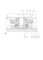
- FIG. 5 is a cross-sectional view showing the structure of a clutch arranged inside the housing deck of the electric work machine with a cutting blade shown in FIG.
- FIG. 5 is an enlarged view of the clutch shown in FIG. 5, and is a cross-sectional view showing a state in which the clutch is disengaged.
- FIG. 5 is an enlarged view of the clutch shown in FIG. 5, and is a cross-sectional view showing a state in which the clutch is engaged.
- the block diagram which shows the control of the electric motor by the control means which concerns on one Embodiment of this invention.
- the external perspective view which shows the vicinity of the clutch lever and the clutch operation detection sensor which concerns on one Embodiment of this invention.
- the flowchart which shows the process from the start of operation to the end of operation in the electric work machine with a cutting blade which concerns on one Embodiment of this invention.
- FIG. 1 is an external perspective view of an electric working machine 1 with a cutting blade (hereinafter, simply referred to as “working machine 1”) according to an embodiment of the present invention
- FIG. 2 is a perspective view showing the inside of a motor box 2.
- FIG. 3 is a perspective view of the working machine 1 as viewed from the handle side
- FIG. 4 is a perspective view of the working machine 1 as viewed from the back surface side.
- the working machine 1 will be described with an example of a walking lawn mower, but as will be described later, the present invention relates to the control of an electric motor that rotationally drives the cutting blade via a clutch, and this control
- the object of application may be any one having a similar cutting blade rotation mechanism, for example, a riding lawn mower or a grass mower.
- FIG. 1 a front wheel 3 is attached to the front of the motor box 2, and a rear wheel 4 is attached to the rear.
- an electric motor 5 is mounted inside the motor box 2.
- the rear wheel 4 and the cutting blade 9 are rotationally driven by the electric motor 5.
- a battery 6 which is a power source for the electric motor 5 is mounted behind the motor box 2.
- the cutting blade 9 is arranged in the housing deck 7.
- the rotation of the electric motor 5 is transmitted to the cutting blade 9 via the clutch 20 (see FIG. 5), and the cutting blade 9 rotates.
- the finned disc 35 rotates integrally with the rotation of the cutting blade 9, and an air flow from the housing deck 7 to the glass bag 8 is generated.
- the grass cut by the rotation of the cutting blade 9 is sent to the glass bag 8 through the exhaust port 19 and collected there.
- the work machine 1 is used by an operator while walking.
- an operation paddle 10 is attached to the machine body, and an operation handle 11 and a clutch lever 12 (clutch) are attached to the end of the operation paddle 10.
- the operating means) and the speed change lever 13 are attached.
- a frame 15 is bridged between the pair of operating paddles 10, and a display 16 for displaying the rotation speed of the electric motor 5 and the like is fixed to the frame 15.
- a main switch 17 is attached to the display 16, and the main power supply can be turned on by rotating the main switch 17.
- the electric motor 5 can be started by sliding the shift lever 13 (direction of arrow a) while the main power supply is ON, and the rotation of the electric motor 5 can be increased stepwise.
- An operation lever 14 is attached in the vicinity of the operation handle 11, and while the electric motor 5 is rotating, the operation of the operation lever 14 drives the rear wheel 4 and advances the work machine 1.
- FIG. 5 is a cross-sectional view showing the structure of the clutch 20 arranged inside the housing deck 7
- FIGS. 6 and 7 are enlarged views of the clutch 20, and
- FIG. 6 shows a state in which the clutch 20 is disengaged.
- FIG. 7 shows a state in which the clutch 20 is engaged.
- the clutch 20 is arranged inside the housing deck 7, and the motor shaft 21 of the electric motor 5 (see FIG. 2) arranged above the housing deck 7 is connected to the drive disk 22. ing.
- the motor shaft 21 and the drive disk 22 are connected by a key (not shown), and the drive disk 22 rotates integrally with the rotation of the motor shaft 21.
- a brake disc support plate 24 is attached to the motor shaft 21 via the upper bearing 23.
- An annular brake disc 25 is attached to the brake disc support plate 24 so as to be movable in the vertical direction.
- the upper bearing 23 is interposed between the motor shaft 21 and the brake disc support plate 24, so that the brake disc support plate 24 and the brake disc 25 integrated with the upper bearing 23 are interposed. Does not rotate.
- the cutting blade 9 is fixed to the lower side of the blade holder 26, and a lower bearing 27 is interposed between the blade holder 26 and the drive disk 22.
- a friction plate 28 is slidably connected to the upper side of the blade holder 26 so as to prevent rotation. When the friction plate 28 rotates, the blade holder 26 and the cutting blade 9 rotate integrally with the friction plate 28.
- a spring 29 is interposed between the blade holder 26 and the friction plate 28, and the friction plate 28 slides in the vertical direction as the spring 29 expands and contracts.
- the friction plate 28 is pressed by the brake disc 25 and slides downward, and the spring 29 is contracted. Therefore, the friction plate 28 is separated from the drive disk 22.
- the clutch 20 is disengaged, and even if the drive disk 22 rotates integrally with the rotation of the motor shaft 21, the rotation of the drive disk 22 is not transmitted to the friction plate 28 and the cutting blade 9 does not rotate either. ..
- the work machine 1 has a state in which the brake disc 25 is pushed downward to disengage the clutch 20 (state in FIG. 6) and a state in which the disengaged state of the clutch 20 is released and the clutch 20 is engaged (state in FIG. 7). It is equipped with a switching mechanism (not shown) that switches between. This switching mechanism is operated by operating the clutch lever 12 (see FIG. 1).
- the work machine 1 has a built-in control means 30 (computer) for controlling the operation of the electric motor 5, and the control of the electric motor 5 by the control means 30 will be described below.
- FIG. 8 is a block diagram showing control of the electric motor 5 by the control means 30,
- FIG. 9 is an external perspective view showing the vicinity of the clutch lever 12 and the clutch operation detection sensor 31, and
- FIG. 10 is an external perspective view showing the vicinity of the clutch lever 12 and the clutch operation detection sensor 31.
- FIG. It is a flowchart which shows the process up to.
- a signal from the clutch operation detection sensor 31 is input to the control means 30, and the control means 30 controls the operation of the electric motor 5 in response to this signal.
- the clutch operation detection sensor 31 is provided below the clutch lever 12.
- the clutch operation detection sensor 31 includes a detection button 32, and in the state of FIG. 9 (a state in which the clutch lever 12 is not operated), the detection button 32 is pressed by a pressing plate 33 fixed to the clutch lever 12. ..
- the signal value of the clutch operation detection sensor 31 when the clutch 20 is disengaged is set. Is a signal value indicating the release of the clutch 20 in the disengaged state, and the control means 30 can recognize the release of the clutch 20 in the disengaged state.
- step 100 when the operation is started (step 100), the main power supply is turned on by rotating the main switch 17 (see FIG. 3) (step 101). By sliding the shift lever 13 (see FIG. 1) in this state, the electric motor 5 is activated (step 102) and the electric motor 5 is rotated (step 103). In this state, in FIG. 1, the rear wheel 4 is driven by the operation of the operating lever 14, and the working machine 1 moves forward.
- This control is to stop the energization of the electric motor 5 during the period including the moment when the clutch 20 is engaged, and the energization stop period of the electric motor 5 may include the moment when the clutch 20 is engaged.
- the rotation of the electric motor 5 is stopped from the release of the clutch 20 to the elapse of the specified time, but it is instantaneous from the release of the clutch 20 to the engagement of the clutch 20. Even if the specified time is as short as about 0.5 seconds, the rotation stop period of the electric motor 5 includes the moment when the clutch 20 is engaged.
- the specified time for stopping the rotation of the electric motor 5 is not particularly limited, but is, for example, in the range of 0.5 seconds to 1 second.
- the control means 30 restarts the electric motor 5 (step 107), and the electric motor 5 rotates again (step 103). In this state, the clutch 20 is engaged, and the cutting blade 9 is rotated by the rotation of the electric motor 5.
- the basic structural configuration is the same as the work machine 1 according to the embodiment, but the electric motor 5 is stopped from being energized from the release of the clutch 20 to the elapse of the specified time. It is a specification that the control to make (hereinafter referred to as "energization stop control”) is not executed. That is, the electric motor 5 continues to rotate regardless of the operation of the clutch 20.
- the embodiment is a specification in which energization stop control is added to the comparative example. For Comparative Examples and Examples, a voltage measuring probe and a current measuring probe were connected, and the voltage value and the current value were measured in time series using a data logger.
- FIG. 11 shows the waveforms of the current I and the voltage V of the electric motor 5 for the comparative example.
- the horizontal axis is the elapsed time t (s), and the vertical axis shares the current I (A) and the voltage V (V) (the same applies to FIG. 12).
- the clutch 20 is engaged and the cutting blade 9 is rotating during the period T1 after the start of measurement.
- the clutch 20 is disengaged, the rotation of the electric motor 5 continues, but the rotation of the cutting blade 9 is stopped.
- the voltage V is rising and the current I is falling.
- the period T3 (9 seconds) following the period T2 is a state in which the clutch 20 is engaged.
- the voltage V drops (part A) and the current I rises sharply (part B). It is considered that this is because the load suddenly increased due to the clutch 20 being engaged.
- the current I then drops and eventually stabilizes (part C).
- the waveforms of the current and voltage in the period T1 and the period T2 are the same as those in FIG. 11 according to the comparative example, but the waveforms in the period T3 are significantly different between FIGS. 11 and 12.
- the current value drops to near zero at the beginning of the period T3 (part D). This is because the energization stop control is executed and the energization of the electric motor 5 is stopped. It is presumed that the current value is not completely zero due to the energization of the sensors and the characteristics of the three-phase motor.
- the energization stop time is set to 0.5 seconds, and 0.5 seconds after the energization of the electric motor 5 is stopped, the electric motor 5 restarts and the cutting blade 9 rotates at the same time. After restarting, the current rises as a whole (part E), then falls (part F), and finally stabilizes (part G).
- the example is a comparative example. Power consumption is expected to be reduced compared to.
- the operating time from when the battery was fully charged to when the electric motor 5 was stopped due to battery discharge was measured in Comparative Examples and Examples. Similar to the above experiment, one cycle was set to 10 seconds, the state in which the clutch 20 was engaged was set to 9 seconds, and the state in which the clutch 20 was disengaged was set to 1 second. The experimental results are shown in Table 1 below.
- the number of cycles in the comparative example was 309, while the number of cycles in the example was 434, and the number of cycles in the example increased by 40% compared to the comparative example (operating time). 40% increase), and the effect of power consumption reduction could be confirmed. From this result, it can be understood that the sudden increase in current at the moment when the clutch 20 is engaged is a major factor for increasing the power consumption.
- the electric motor 5 is restarted as in the embodiment, the power consumption is reduced as compared with the comparative example, although a large load is applied at the time of restarting. This is because the electric motor has a characteristic of generating a large torque at the time of starting, and it is considered that the restart of the electric motor 5 is not a factor that greatly increases the power consumption.
- the effect of reducing power consumption is due to suppressing a sudden increase in current at the moment when the clutch 20 is engaged, the effect of reducing power consumption increases as the frequency of engagement and disengagement of the clutch 20 increases.
- the walking lawn mower as shown in FIG. 1 is used in a narrow area, the clutch 20 is frequently engaged and disconnected, and power consumption can be reduced more effectively.
- the clutch lever 12 is used as the operating means of the clutch 20, but the clutch 20 is not limited to the lever structure as long as the clutch 20 can be operated.
- the detection of the release of the clutch 20 in the disengaged state is based on the change in the signal value output from the clutch operation detection sensor 31 by the operation of the clutch lever 12, but the clutch 20 is disengaged. Any other method may be used as long as it can detect the release of.
- the energization stop control in the above embodiment is a control for stopping the energization of the electric motor 5 when the clutch 20 is released, but the energization stop timing is not limited to this, and at least the clutch It suffices if the energization is stopped at the moment when 20 is connected.
Landscapes
- Life Sciences & Earth Sciences (AREA)
- Environmental Sciences (AREA)
- Harvester Elements (AREA)
- Dicing (AREA)
Abstract
Description

3 前輪
4 後輪
5 電動モータ
9 刈刃
12 クラッチレバー(クラッチの操作手段)
18 操作ボタン
20 クラッチ
22 ドライブディスク
28 摩擦板
30 制御手段
31 クラッチ作動センサ
Claims (2)
- 刈刃と、
前記刈刃を回転駆動する電動モータと、
前記電動モータと前記刈刃との間で動力を断接するクラッチと、
前記クラッチを操作する操作手段と、
前記電動モータの運転を制御する制御手段とを備えており、
前記操作手段により、前記電動モータの動力が前記刈刃に伝達されない前記クラッチを切った状態と前記電動モータの動力が前記刈刃に伝達される前記クラッチが繋がった状態とを切り換え可能であり、
前記制御手段は、前記クラッチを切った状態の解除以降に前記電動モータの通電を停止させ、前記通電の停止から規定時間経過後に前記電動モータを再起動させることにより、前記クラッチが繋がった瞬間を含む期間において、前記電動モータの回転を停止させることを特徴とする刈刃付き電動作業機。 - 前記制御手段は、前記クラッチを切った状態の解除を、前記操作手段の動きを検知するセンサからの信号に基づいて認識する請求項1に記載の刈刃付き電動作業機。
Priority Applications (9)
| Application Number | Priority Date | Filing Date | Title |
|---|---|---|---|
| EP19928459.7A EP3967124B1 (en) | 2019-05-10 | 2019-05-10 | Power-assisted work machine with cutting blade |
| BR112021021023-7A BR112021021023B1 (pt) | 2019-05-10 | Máquina de trabalho elétrica com lâmina de corte | |
| US17/432,301 US20220338412A1 (en) | 2019-05-10 | 2019-05-10 | Electric work machine with cutting blade |
| CN201980092297.XA CN113473841B (zh) | 2019-05-10 | 2019-05-10 | 带刀片的电动作业机 |
| JP2021519051A JP7184400B2 (ja) | 2019-05-10 | 2019-05-10 | 刈刃付き電動作業機 |
| AU2019445992A AU2019445992B2 (en) | 2019-05-10 | 2019-05-10 | Electric Work Machine with Cutting Blade |
| KR1020217026575A KR102677075B1 (ko) | 2019-05-10 | 2019-05-10 | 커팅날이 구비된 전동 작업기 |
| PCT/JP2019/018802 WO2020230208A1 (ja) | 2019-05-10 | 2019-05-10 | 刈刃付き電動作業機 |
| TW108128023A TWI778288B (zh) | 2019-05-10 | 2019-08-07 | 具有刀片的電動作業機 |
Applications Claiming Priority (1)
| Application Number | Priority Date | Filing Date | Title |
|---|---|---|---|
| PCT/JP2019/018802 WO2020230208A1 (ja) | 2019-05-10 | 2019-05-10 | 刈刃付き電動作業機 |
Publications (1)
| Publication Number | Publication Date |
|---|---|
| WO2020230208A1 true WO2020230208A1 (ja) | 2020-11-19 |
Family
ID=73289514
Family Applications (1)
| Application Number | Title | Priority Date | Filing Date |
|---|---|---|---|
| PCT/JP2019/018802 Ceased WO2020230208A1 (ja) | 2019-05-10 | 2019-05-10 | 刈刃付き電動作業機 |
Country Status (8)
| Country | Link |
|---|---|
| US (1) | US20220338412A1 (ja) |
| EP (1) | EP3967124B1 (ja) |
| JP (1) | JP7184400B2 (ja) |
| KR (1) | KR102677075B1 (ja) |
| CN (1) | CN113473841B (ja) |
| AU (1) | AU2019445992B2 (ja) |
| TW (1) | TWI778288B (ja) |
| WO (1) | WO2020230208A1 (ja) |
Families Citing this family (1)
| Publication number | Priority date | Publication date | Assignee | Title |
|---|---|---|---|---|
| EP4311418B1 (en) | 2022-07-29 | 2026-04-22 | Techtronic Cordless GP | Transmission with centrifugal clutch mechanism |
Citations (5)
| Publication number | Priority date | Publication date | Assignee | Title |
|---|---|---|---|---|
| US4995227A (en) * | 1989-10-25 | 1991-02-26 | Foster Harry C | Power assisted reel type lawn mower |
| JP2001046784A (ja) * | 1999-08-10 | 2001-02-20 | Hitachi Ltd | 全自動洗濯機及び全自動洗濯機の制御方法 |
| JP2007222026A (ja) * | 2006-02-21 | 2007-09-06 | Kubota Corp | 電動作業機 |
| JP2014239660A (ja) | 2013-06-11 | 2014-12-25 | 株式会社クボタ | 歩行型草刈機 |
| WO2018021427A1 (ja) * | 2016-07-26 | 2018-02-01 | 株式会社コーク | 高圧エヤ発生装置 |
Family Cites Families (14)
| Publication number | Priority date | Publication date | Assignee | Title |
|---|---|---|---|---|
| US4882897A (en) * | 1987-11-28 | 1989-11-28 | Kubota, Ltd. | Clutch control structure for a walking operator type lawn mower |
| EP0817352A2 (en) * | 1992-08-18 | 1998-01-07 | Black & Decker Inc. | Improvements in battery operated electric machines |
| CA2195995C (en) * | 1994-08-22 | 2001-02-06 | Patrick J. Bruener | Improved battery-powered lawn cutting system |
| JP3192961B2 (ja) * | 1996-02-22 | 2001-07-30 | 本田技研工業株式会社 | 歩行型作業機の操作レバー装置 |
| JP2002303229A (ja) * | 2001-04-03 | 2002-10-18 | Orec Co Ltd | 作業機の始動安全装置、それを備えた作業機及び作業機の始動時の安全を図る方法 |
| TWI248783B (en) * | 2001-08-22 | 2006-02-11 | Honda Motor Co Ltd | Electric lawn mower |
| JP2003061432A (ja) * | 2001-08-22 | 2003-03-04 | Honda Motor Co Ltd | 電動芝刈機 |
| US7470209B2 (en) * | 2005-11-23 | 2008-12-30 | Gm Global Technology Operations, Inc. | Hybrid powertrain having an electrically variable transmission and engine valve control |
| JP2013169612A (ja) * | 2012-02-20 | 2013-09-02 | Duplo Corp | 断裁装置 |
| EP2905493B1 (de) * | 2014-02-08 | 2019-01-09 | Andreas Stihl AG & Co. KG | Arbeitsgerät mit einer Kupplung |
| JP6206970B2 (ja) * | 2014-09-18 | 2017-10-04 | 東洋電装株式会社 | 動力作業機用回転電機 |
| KR101729005B1 (ko) * | 2015-02-16 | 2017-04-21 | 인하공업전문대학산학협력단 | 구동모터를 이용한 배부식 예초기 |
| JP6193421B2 (ja) * | 2016-02-29 | 2017-09-06 | 本田技研工業株式会社 | 芝刈機 |
| US9687111B1 (en) * | 2017-02-09 | 2017-06-27 | R. Joseph Trojan | Vacuum blender |
-
2019
- 2019-05-10 EP EP19928459.7A patent/EP3967124B1/en active Active
- 2019-05-10 JP JP2021519051A patent/JP7184400B2/ja active Active
- 2019-05-10 WO PCT/JP2019/018802 patent/WO2020230208A1/ja not_active Ceased
- 2019-05-10 US US17/432,301 patent/US20220338412A1/en not_active Abandoned
- 2019-05-10 CN CN201980092297.XA patent/CN113473841B/zh active Active
- 2019-05-10 KR KR1020217026575A patent/KR102677075B1/ko active Active
- 2019-05-10 AU AU2019445992A patent/AU2019445992B2/en active Active
- 2019-08-07 TW TW108128023A patent/TWI778288B/zh active
Patent Citations (5)
| Publication number | Priority date | Publication date | Assignee | Title |
|---|---|---|---|---|
| US4995227A (en) * | 1989-10-25 | 1991-02-26 | Foster Harry C | Power assisted reel type lawn mower |
| JP2001046784A (ja) * | 1999-08-10 | 2001-02-20 | Hitachi Ltd | 全自動洗濯機及び全自動洗濯機の制御方法 |
| JP2007222026A (ja) * | 2006-02-21 | 2007-09-06 | Kubota Corp | 電動作業機 |
| JP2014239660A (ja) | 2013-06-11 | 2014-12-25 | 株式会社クボタ | 歩行型草刈機 |
| WO2018021427A1 (ja) * | 2016-07-26 | 2018-02-01 | 株式会社コーク | 高圧エヤ発生装置 |
Non-Patent Citations (1)
| Title |
|---|
| See also references of EP3967124A4 |
Also Published As
| Publication number | Publication date |
|---|---|
| BR112021021023A2 (pt) | 2021-12-14 |
| KR20210114526A (ko) | 2021-09-23 |
| CN113473841B (zh) | 2023-01-31 |
| AU2019445992B2 (en) | 2022-12-01 |
| TW202041139A (zh) | 2020-11-16 |
| AU2019445992A1 (en) | 2021-09-09 |
| JP7184400B2 (ja) | 2022-12-06 |
| JPWO2020230208A1 (ja) | 2020-11-19 |
| EP3967124A4 (en) | 2022-12-21 |
| US20220338412A1 (en) | 2022-10-27 |
| KR102677075B1 (ko) | 2024-06-21 |
| CN113473841A (zh) | 2021-10-01 |
| TWI778288B (zh) | 2022-09-21 |
| EP3967124A1 (en) | 2022-03-16 |
| EP3967124B1 (en) | 2024-09-18 |
Similar Documents
| Publication | Publication Date | Title |
|---|---|---|
| WO2020230212A1 (ja) | 刈刃付き電動作業機 | |
| CN104159484B (zh) | 食品加工机 | |
| JP4858911B2 (ja) | 草刈り機 | |
| US20150245559A1 (en) | Lawn mower with an automatic clutch | |
| JP5648672B2 (ja) | 草刈機 | |
| JP2017225292A (ja) | 電動機 | |
| JP2014113068A5 (ja) | ||
| WO2020230208A1 (ja) | 刈刃付き電動作業機 | |
| JPWO2021029182A5 (ja) | ||
| CN106385938B (zh) | 割草机 | |
| EP3110670A1 (en) | Drive systems and methods for implementing engine stall protection in a self-propelled machine | |
| JP5605751B2 (ja) | 携帯用切断機 | |
| CN216451942U (zh) | 割草机和电动工具 | |
| JP6555318B2 (ja) | 草刈機 | |
| JP6245290B2 (ja) | 草刈機 | |
| BR112021021023B1 (pt) | Máquina de trabalho elétrica com lâmina de corte | |
| JP6135784B2 (ja) | 草刈機 | |
| JP6131584B2 (ja) | 草刈機 | |
| JP5578000B2 (ja) | 作業車両の原動部構造 | |
| JP2020068703A (ja) | 芝刈機 |
Legal Events
| Date | Code | Title | Description |
|---|---|---|---|
| 121 | Ep: the epo has been informed by wipo that ep was designated in this application |
Ref document number: 19928459 Country of ref document: EP Kind code of ref document: A1 |
|
| ENP | Entry into the national phase |
Ref document number: 2021519051 Country of ref document: JP Kind code of ref document: A |
|
| ENP | Entry into the national phase |
Ref document number: 20217026575 Country of ref document: KR Kind code of ref document: A |
|
| ENP | Entry into the national phase |
Ref document number: 2019445992 Country of ref document: AU Date of ref document: 20190510 Kind code of ref document: A |
|
| REG | Reference to national code |
Ref country code: BR Ref legal event code: B01A Ref document number: 112021021023 Country of ref document: BR |
|
| NENP | Non-entry into the national phase |
Ref country code: DE |
|
| ENP | Entry into the national phase |
Ref document number: 2019928459 Country of ref document: EP Effective date: 20211210 |
|
| ENP | Entry into the national phase |
Ref document number: 112021021023 Country of ref document: BR Kind code of ref document: A2 Effective date: 20211020 |