WO2020230367A1 - Procédé de formage à la presse - Google Patents
Procédé de formage à la presse Download PDFInfo
- Publication number
- WO2020230367A1 WO2020230367A1 PCT/JP2020/001651 JP2020001651W WO2020230367A1 WO 2020230367 A1 WO2020230367 A1 WO 2020230367A1 JP 2020001651 W JP2020001651 W JP 2020001651W WO 2020230367 A1 WO2020230367 A1 WO 2020230367A1
- Authority
- WO
- WIPO (PCT)
- Prior art keywords
- press
- molded product
- top plate
- flange
- molding
- Prior art date
- Legal status (The legal status is an assumption and is not a legal conclusion. Google has not performed a legal analysis and makes no representation as to the accuracy of the status listed.)
- Ceased
Links
Images


Classifications
-
- B—PERFORMING OPERATIONS; TRANSPORTING
- B21—MECHANICAL METAL-WORKING WITHOUT ESSENTIALLY REMOVING MATERIAL; PUNCHING METAL
- B21D—WORKING OR PROCESSING OF SHEET METAL OR METAL TUBES, RODS OR PROFILES WITHOUT ESSENTIALLY REMOVING MATERIAL; PUNCHING METAL
- B21D22/00—Shaping without cutting, by stamping, spinning, or deep-drawing
- B21D22/20—Deep-drawing
- B21D22/26—Deep-drawing for making peculiarly, e.g. irregularly, shaped articles
-
- B—PERFORMING OPERATIONS; TRANSPORTING
- B21—MECHANICAL METAL-WORKING WITHOUT ESSENTIALLY REMOVING MATERIAL; PUNCHING METAL
- B21D—WORKING OR PROCESSING OF SHEET METAL OR METAL TUBES, RODS OR PROFILES WITHOUT ESSENTIALLY REMOVING MATERIAL; PUNCHING METAL
- B21D53/00—Making other particular articles
- B21D53/88—Making other particular articles other parts for vehicles, e.g. cowlings, mudguards
-
- B—PERFORMING OPERATIONS; TRANSPORTING
- B21—MECHANICAL METAL-WORKING WITHOUT ESSENTIALLY REMOVING MATERIAL; PUNCHING METAL
- B21D—WORKING OR PROCESSING OF SHEET METAL OR METAL TUBES, RODS OR PROFILES WITHOUT ESSENTIALLY REMOVING MATERIAL; PUNCHING METAL
- B21D5/00—Bending sheet metal along straight lines, e.g. to form simple curves
- B21D5/01—Bending sheet metal along straight lines, e.g. to form simple curves between rams and anvils or abutments
Definitions
- the present invention relates to a press forming method, and in particular, is a hat-shaped cross section having a top plate portion (web), a vertical wall portion (side wall), and a flange portion (flange).
- the present invention relates to a press molding method for a press molded product that is curved along the longitudinal direction in a plan view.
- Patent Document 1 describes in the press molding of a final molded product having a hat-shaped cross section that is provided with a top surface (web), a side wall (side wall), and a flange and is curved along the longitudinal direction, from the lower end of the side wall in the first step.
- An intermediate molded product (preformed part) having a widening tapered portion and a flange portion extending from the lower end of the tapered portion is formed, and the tapered portion and the flange of the intermediate molded product are remolded into a flat flange in the second step.
- the technology is disclosed, and it is said that the springback of the flange can be suppressed to improve the angle between the flange and the side wall and the flatness of the flange.
- Patent Document 2 when a press-molded part having a cross-section hat shape having a top plate portion, a vertical wall portion and a flange portion is molded into a target shape, in the first molding step, it is outwardly compared with the target shape.
- a technique for molding a preformed part having a vertical wall portion in which a convex mountain-shaped bent portion is formed and molding the temporarily molded part into a press-molded part having a target shape in the second molding step is disclosed. It is said that it is possible to suppress a change in the angle of the flange portion to be joined with other parts.
- Patent Document 1 Although it is possible to suppress the change in the angle between the vertical wall and the flange, the accuracy of the angle of the flange portion is due to the wall warp (wall curl) of the vertical wall after press molding. May decrease.
- Patent Document 2 targets a press-molded product that is straight in the longitudinal direction, and targets a press-molded product having a cross-section hat shape that curves along the longitudinal direction. There is a problem that it is not always possible to suppress the angle change of the flange portion at both the center and the end side in the longitudinal direction of the press-molded product.
- the present invention has been made to solve the above-mentioned problems, and when press-molding a press-molded product having a cross-section hat shape that curves along the longitudinal direction in a plan view, the center and end sides in the longitudinal direction It is an object of the present invention to provide a press forming method in which the accuracy of the angle of the flange portion is improved in both cases.
- the press molding method according to the present invention has a cross-sectional hat shape having a top plate portion, a vertical wall portion continuous from the top plate portion, and a flange portion continuous from the vertical wall portion, and is in the longitudinal direction in a plan view.
- a press-molded product that curves along the line is press-molded, and the top plate portion and flange portion having the same shape as the target shape of the press-molded product are compared with the target shape of the press-molded product in the press-molding direction. It includes a first molding step of press-molding an intermediate molded product having a chevron-shaped vertical wall portion having a convex cross section outward, and a second molding step of press-molding the intermediate molded product into the target shape.
- the vertical wall portion in the first molding step includes a top plate side surface portion (punch shoulder of panel) connected to the top plate portion, a flange side surface portion (die shoulder of panel) connected to the flange portion, and the top plate. It has a bent portion (bent portion) between the side surface portion and the side surface portion of the flange, and the angle on the sharp angle side formed by the side surface portion of the top plate and the horizontal plane decreases from the center in the longitudinal direction toward the end portion. Is set to.
- the press molding method according to the present invention has a cross-sectional hat shape having a top plate portion, a vertical wall portion continuous from the top plate portion, and a flange portion continuous from the vertical wall portion, and is in the longitudinal direction in a plan view.
- a press-molded product that curves along the line is press-molded into a target shape, and a top plate portion and a flange portion having the same shape as the target shape of the press-molded product are pressed in comparison with the target shape of the press-molded product.
- the vertical wall portion in the first molding step includes a top plate side surface portion connected to the top plate portion, a flange side surface portion connected to the flange portion, and the top plate side surface portion and the flange side surface portion. It has a bent portion between them, and is set so that the height from the top plate portion to the bent portion in the press forming direction increases from the center to the end portion in the longitudinal direction.
- the wall warpage of the vertical wall portion due to the springback of the press-molded product curved in the longitudinal direction in a plan view is suppressed, and the angle change of the flange portion due to the wall warp is reduced over the entire length in the longitudinal direction. It is possible to press-mold the angle of the flange portion with high accuracy.
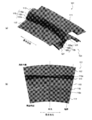
- FIG. 1 is a diagram illustrating an intermediate molded product press-molded in the press molding method according to the first embodiment of the present invention and a press-molded product having a target shape ((a) perspective view of the intermediate molded product, (B) Cross-sectional view of the intermediate molded product, (c) Perspective view of the press-molded product).
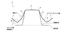
- FIG. 2 is a diagram illustrating a change in the angle of the flange portion due to springback of the press-molded product to be molded in the present invention.
- FIG. 3 is a diagram illustrating parameters that define the shape of an intermediate molded product that is press-molded in the press-molding method according to the present invention.
- FIG. 4 is a diagram showing an example of a mold (tool of press forming) used in the first molding step of press molding an intermediate molded product in the press molding method according to the first embodiment of the present invention ((a) perspective view.
- FIG. (B) Plan view of the die as seen from the punch side).
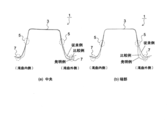
- FIG. 5 is a cross-sectional view for explaining the effect of suppressing springback due to the difference in the angle of the vertical wall portion of the intermediate molded product in the press molding method according to the first embodiment of the present invention ((a) center in the longitudinal direction. , (B) Longitudinal end).
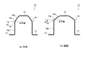
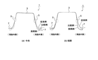
- FIG. 6 is a cross-sectional view illustrating an intermediate molded product in the press molding method according to the second embodiment of the present invention ((a) center in the longitudinal direction, (b) end in the longitudinal direction).
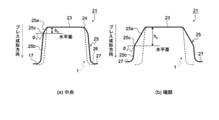
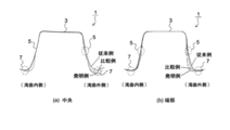
- FIG. 7 is a diagram for explaining the effect of suppressing springback due to the difference in the height of the bent portion of the intermediate molded product in the press molding method according to the second embodiment of the present invention ((a) center in the longitudinal direction, (B) Longitudinal end, (b') Wall warpage due to springback at longitudinal end).
- FIG. 8 is a diagram showing the result of the cross-sectional shape of the press-formed product after springback in this embodiment (No. 1).
- FIG. 1 is a diagram for explaining the effect of suppressing springback due to the difference in the height of the bent portion of the intermediate molded product in the press molding method according to the second embodiment of the present invention ((a) center in the longitudinal direction, (B) Longitudinal end, (b') Wall warpage due to springback at longitudinal end
- FIG. 9 is a diagram showing the result of the cross-sectional shape of the press-formed product after springback in this embodiment (No. 2).
- FIG. 10 is a diagram showing the result of the cross-sectional shape of the press-formed product after springback in this embodiment (No. 3).
- FIG. 11 is a diagram showing the result of the cross-sectional shape of the press-formed product after springback in this embodiment (No. 4).
- the press-molded product 1 to be molded in the present invention has a top plate portion 3, a vertical wall portion 5 continuous from the top plate portion 3, and a flange portion continuous from the vertical wall portion 5. It is curved along the longitudinal direction in a plan view of a cross-sectional hat shape having 7 and.
- the press molding method according to the first embodiment of the present invention is, for example, press molding a press-molded product 1 as shown in FIG. 1 (c), and as an example, FIGS. 1 (a) and 1 (b). ), It has a first molding step of press-molding the intermediate molded product 11 and a second molding step of press-molding the intermediate molded product 11 into the press-molded product 1 having a target shape.
- the top plate portion 13 and the flange portion 17 having the same shape as the target shape of the press-molded product 1 and the target shape of the press-molded product 1 are formed.
- the vertical wall portion 15 includes a top plate side surface portion 15a connected to the top plate portion 13, a flange side surface portion 15b connected to the flange portion 17, and a bent portion 15c between the top plate side surface portion 15a and the flange side surface portion 15b.
- the shape of the vertical wall portion 15 is the height h from the top plate portion 13 to the bent portion 15c in the cross section in the press molding direction, and the acute angle side formed by the top plate side surface portion 15a and the horizontal plane.
- the angle ⁇ and the angle ⁇ formed by the flange side surface portion 15b and the horizontal plane are defined.
- the angle ⁇ on the acute angle side formed by the top plate side surface portion 15a and the horizontal plane is the center in the longitudinal direction (angle ⁇ c). ) To the end (angle ⁇ s ).
- the intermediate molded product 11 can be press-molded using, for example, a mold 101 having a die 111 and a punch 121 as shown in FIG.
- the die 111 and the punch 121 are formed by the top plate forming portions (tool portion which forms web) 113 and 123, the vertical wall forming portions (tool portion which forms side wall) 115 and 125, and the flange forming portions (tool portion which). forms flange) 117 and 127, respectively.
- the top plate forming portions 113 and 123 and the flange forming portions 117 and 127 form the top plate portion 3 and the flange portion 7 having the same shape as the target shape of the press-molded product 1.
- the vertical wall forming portions 115 and 125 form the vertical wall portion 15 having a mountain shape whose cross section is convex outward in the press forming direction as compared with the target shape of the press molded product 1.
- vertical wall portions 15 are formed on the inner and outer sides of the curve along the longitudinal direction in a plan view. Then, the angle ⁇ formed by the top plate side surface portion 15a and the horizontal plane is set to decrease from the center in the longitudinal direction toward the end portion on both the inside of the curve and the outside of the curve of the vertical wall portion 15.
- the angle ⁇ formed by the flange side surface portion 15b and the horizontal plane may be set to the same angle as the angle formed by the vertical wall portion 5 of the press-formed product 1 having the target shape and the horizontal plane.
- the second molding step is a step of press-molding the intermediate molded product 11 press-molded in the first molding step into the press-molded product 1 having the target shape.
- the vertical wall portion 15 of the intermediate molded product 11 is press-molded into the vertical wall portion 5 having the same shape as the target shape.
- the angle ⁇ formed by the top plate side surface portion 15a and the horizontal plane in the intermediate molded product 11 is set so that the angle ⁇ s at the end portion in the longitudinal direction is smaller than the angle ⁇ c at the center in the longitudinal direction. (Fig. 1 (b)). That is, the top plate side surface portion 15a has a small spread outward in the horizontal plane direction at the center in the longitudinal direction and a large spread outward in the same direction at the end portion in the longitudinal direction.
- the parameters that define the shape of the intermediate molded product 11 molded in the first molding step are the following (i) and (ii) with reference to the target shape of the press-molded product 1 (see FIGS. 1 and 2). ) And (iii) shall be satisfied.
- the width w of the top plate portion 13 of the intermediate molded product 11 is the same as the width of the top plate portion 3 of the press-molded product 1 having the target shape.
- L cross-sectional line length of the vertical wall portion 15
- the angle ⁇ formed by the flange side surface portion 15b and the horizontal plane in the intermediate molded product 11 is the same as the angle formed by the vertical wall portion 5 and the horizontal plane of the press molded product 1 having the target shape.
- the bent portion 15c in the vertical wall portion 15 whose shape is defined under these assumptions (i) to (iii) is bent (reverse) in the direction opposite to the wall warp due to the conventional springback shown in FIG. bending)). Therefore, by molding the vertical wall portion 15 into the target shape in the second molding step, a spring-go component is imparted to the vertical wall portion 5.
- the small angle ⁇ formed by the top plate side surface portion 15a and the horizontal plane in the intermediate molded product 11 molded in the first molding step means that the top plate side surface portion 15a and the flange side surface portion 15b in the vertical wall portion 15 are bent. It means that it becomes larger (see FIG. 1 (b)). Therefore, the smaller the angle ⁇ of the vertical wall portion 15, the larger the spring-go component given to the vertical wall portion 5 in the process of molding the vertical wall portion 15 into the target shape in the second molding step, and the larger the vertical wall portion 5 becomes. Wall warpage is more suppressed. As a result, the change in the angle of the flange portion 7 can be reduced.
- the angle ⁇ formed by the top plate side surface portion 15a and the horizontal plane in the intermediate molded product 11 is at the end portion as compared with the angle ⁇ c at the center in the longitudinal direction.
- the angle ⁇ s is set to be small, and the reason is as follows.
- the restraint (rigidity due to the shape) is weak, and the amount of springback increases even if the same springback driving force (residual stress) acts. It occurs greatly. Therefore, as shown in FIG. 5B, the angle ⁇ s at the end portion in the longitudinal direction of the intermediate molded product 11 is made smaller than that at the center to enhance the springback suppressing effect.
- the angle ⁇ formed by the top plate side surface portion 15a of the intermediate molded product 11 and the horizontal plane is reduced from the center in the longitudinal direction toward the end portion. It is possible to suppress the wall warp of the vertical wall portion 5 over the entire length in the longitudinal direction and reduce the change in the angle of the flange portion 7.
- the height h from the top plate portion 13 to the bent portion 15c is increased from the center in the longitudinal direction toward the end portion, so that the angle ⁇
- the synergistic effect of suppressing the wall warp of the vertical wall portion 5 by the height h and the height h can be obtained, and the angle change of the flange portion 7 can be further reduced.
- the press molding method according to the second embodiment of the present invention is, for example, press molding a press-molded product 1 as shown in FIG. 1 (c), and has a cross-sectional shape as shown in FIG. 6 as an example. It includes a first molding step of press-molding the intermediate molded product 21 and a second molding step of press-molding the intermediate molded product 21 into the press-molded product 1 having a target shape.
- the vertical wall portion 25 includes a top plate side surface portion 25a connected to the top plate portion 23, a flange side surface portion 25b connected to the flange portion 27, and a bent portion 25c between the top plate side surface portion 25a and the flange side surface portion 25b.
- the shape of the vertical wall portion 25 is the height h from the top plate portion 23 to the bent portion 25c in the cross section in the press molding direction, similarly to the intermediate molded product 11 (FIG. 3) in the first embodiment described above. It is defined by the angle ⁇ formed by the side surface portion 25a of the top plate and the horizontal plane on the acute angle side, and the angle ⁇ formed by the side surface portion 25b of the flange and the horizontal plane.
- the height h from the top plate portion 23 to the bent portion 25c in the press molding direction of the intermediate molded product 21 is the center in the longitudinal direction. Set so that it increases from (height h c ) to the end (height h s ).
- vertical wall portions 25 are formed on the inner and outer sides of the curvature along the longitudinal direction in a plan view. Then, the height h from the top plate portion 23 to the bent portion 25c is set to increase from the center to the end portion in the longitudinal direction on both the inside of the curved side and the outside of the curved portion 25 of the vertical wall portion 25.
- the angle ⁇ formed by the flange side surface portion 25b and the horizontal plane may be set to the same angle as the angle formed by the vertical wall portion 5 of the target shape and the horizontal plane.
- the second molding step is a step of press-molding the intermediate molded product 21 press-molded in the first molding step into the press-molded product 1 having the target shape.
- the vertical wall portion 25 of the intermediate molded product 21 is press-molded into the vertical wall portion 5 having the same shape as the target shape.
- the bent portion 25c in the intermediate molded product 21 has a small height h c at the center in the longitudinal direction (close to the top plate portion 23) and a large height h s at the end portion in the longitudinal direction (top). Move away from the board 23).
- each parameter (see FIG. 3) that defines the shape of the intermediate molded product 21 molded in the first molding step is the following (i'), (ii') with reference to the target shape of the press molded product 1. And (iii') shall be satisfied.
- the width w of the top plate portion 23 of the intermediate molded product 21 is the same as the width of the top plate portion 3 of the press-molded product 1 having the target shape.
- the length L of the ridgeline from the punch shoulder R portion 24 to the die shoulder R portion 26 of the intermediate molded product 21 is a target. It is the same as the length of the ridge line (cross-sectional line length of the vertical wall portion 5) from the punch shoulder R portion 4 to the die shoulder R portion 6 of the press-formed product 1 having a shape.
- the angle ⁇ formed by the flange side surface portion 25b and the horizontal plane in the intermediate molded product 21 is the same as the angle formed by the vertical wall portion 5 and the horizontal plane of the press molded product 1.
- the bent portion 25c of the vertical wall portion 25 whose shape is defined based on these assumptions (i') to (iii') is bent (reverse bent) in the direction opposite to the wall warp due to the conventional springback shown in FIG. Has been done. Therefore, the spring-go component is imparted to the vertical wall portion 5 by molding the vertical wall portion 25 into the target shape in the second molding step.
- the magnitude of the spring-go component depends on the bending of the top plate side surface portion 15a and the flange side surface portion 15b in the vertical wall portion 15, that is, the angle ⁇ formed by the top plate side surface portion 25a and the horizontal plane. Therefore, even if the height h from the top plate portion 23 to the bent portion 25c is changed under the same condition that the angle ⁇ formed by the top plate side surface portion 25a and the horizontal plane is the same, the height h is applied to the vertical wall portion 5 in the second molding step.
- the size of the spring-go component is the same.
- the height h from the top plate portion 23 to the bent portion 25c in the intermediate molded product 21 molded in the first molding step is large, the length (height in the press molding direction) of the flange side surface portion 25b becomes short. ..
- the top plate side surface portion 25a of the intermediate molded product 21 has almost no wall warp, whereas the flange side surface portion 25b has a large wall warp. Therefore, in the second molding step, if the length (height in the press molding direction) of the flange side surface portion 25b is short, springback due to wall warpage of the vertical wall portion 5 can be suppressed. As a result, the change in the angle of the flange portion 7 can be reduced.
- the press molding method according to the second embodiment is intermediate molding as described above, based on the relationship between the height from the top plate portion 3 to the bent portion 25c and the angle change of the flange portion 7 due to the spring back.
- the height h from the top plate portion 3 to the bent portion 25c in the product 21 is set so that the height h s at the end portion in the longitudinal direction is larger than the height h c at the center in the longitudinal direction.
- the reason is as follows.
- the restraint (rigidity due to the shape) by the materials on both sides in the longitudinal direction is strong, and the amount of springback is small even if the same springback driving force (residual stress) acts. Therefore, as shown in FIG. 7A, even if the height h c from the top plate portion 23 to the bent portion 25 c is reduced and the height h bc of the flange side surface portion 25 b is increased, the flange side surface portion 25 b is formed. The amount of springback due to wall warpage remains small.
- the height h from the top plate portion 23 to the bent portion 25c of the intermediate molded product 21 is increased from the center to the end portion in the longitudinal direction.
- the wall warp of the vertical wall portion 5 can be suppressed over the entire length in the longitudinal direction, and the angle change of the flange portion 7 can be reduced.
- the angle ⁇ formed by the top plate side surface portion 25a and the horizontal plane is reduced from the center in the longitudinal direction toward the end portion, so that the angle ⁇ and the height h are determined.
- the synergistic effect of reducing the wall warp of the vertical wall portion 5 can be obtained, and the angle change of the flange portion 7 can be further reduced.
- a press-molded product 1 having a cross-section hat shape that curves along the longitudinal direction in a plan view shown in FIG. 1 (c) was targeted for molding, and was compared with the vertical wall portion 5 having the target shape in the first molding step.
- An intermediate molded product having a mountain-shaped vertical wall portion convex to the outside was press-molded, and in the subsequent second molding step, the intermediate molded product was press-molded into a press-molded product 1 having a target shape. Then, in the second molding step, the angle change of the flange portion 7 after the release of the press-molded product 1 press-molded to the bottom dead center of molding was obtained.
- the dimensions of the target shape of the press-molded product 1 are: the radius of curvature of the curve is 500 mm or 1000 mm, the width of the top plate 3 is 60 mm, the molding height is 60 mm, the angle between the vertical wall 5 and the horizontal plane is 85 degrees, and the punch is punched.
- the radius of curvature of the shoulder R portion 4 was 5 mm, and the radius of curvature of the die shoulder R portion 6 was 8 mm.
- the metal plate used for press molding of the press-formed product 1 was a steel plate having a thickness of 1.2 mm and a tensile strength of 980 MPa.
- the intermediate molded product 11 is press-molded into the press-molded product 1 having the target shape, and the flange portion by the springback of the press-molded product 1 is based on the joint surface (horizontal plane) of the flange portion 7 having the target shape.
- the angle change of 7 was obtained.
- the angle ⁇ formed by the top plate side surface portion 15a and the horizontal plane is, as shown in Tables 1 and 2, the curved inner side and curved outer side of the intermediate molded product 11 that is curved along the longitudinal direction.
- the angles ⁇ is (inside the curve) and ⁇ os (inside the curve) at the ends in the longitudinal direction (170 mm from the center) compared to the angles ⁇ ic (inside the curve) and ⁇ oc (outside the curve) in the center of the longitudinal direction.
- the outside of the curve was set to be small ( ⁇ is ⁇ ic , ⁇ os ⁇ oc ).
- the height h from the top plate portion 13 to the bent portion 15c in the intermediate molded product 11 was set to 30 mm, and the radius of curvature (curvature radius) R of the bent portion 15c was set to 15 mm.
- the width of the top plate portion 13 and the width of the flange portion 17 of the intermediate molded product 11 are the same as those of the press molded product 1 having the target shape.
- the length of the ridge line from the punch shoulder R portion 14 to the die shoulder R portion 16 cross-sectional line length of the vertical wall portion 15
- the angle of the flange side surface portion 15b with respect to the horizontal plane in the intermediate molded product 11 are respectively press-molded products.
- the length of the ridge line from the punch shoulder R portion 4 to the die shoulder R portion 6 cross-sectional line length of the vertical wall portion 5 and the angle of the vertical wall portion 5 with respect to the horizontal plane were set to be the same.
- the angle change of the flange portion 7 after the release of the press-formed product 1 was evaluated by the flange angle ⁇ with respect to the joint surface (horizontal plane) of the flange portion 7 of the target shape (see FIG. 2).
- a press-molded product 1 having a target shape in one step is used as a conventional example, and both the angle ⁇ of the top plate side surface portion 15a and the horizontal plane and the height h of the bent portion 15c are in the longitudinal direction.
- a press-molded product 1 having a target shape is press-molded in two steps, a first molding step of press-molding the intermediate molded product 11 having a constant vertical wall portion 15 and a second molding step of press-molding the intermediate molded product 11.
- the change in the angle of the flange portion 7 due to the springback was evaluated for each of them.
- FIGS. 8 and 9 show the cross-sectional shapes of the press-formed product 1 having curved radii of curvature of 500 mm and 1000 mm, respectively, after springback. From FIGS. 8 and 9, in the comparative example and the invention example in which the press-molded product 1 having the target shape is press-molded in two steps as compared with the conventional example, the wall warp of the vertical wall portion 5 is obtained regardless of the radius of curvature of any of the curves. Is suppressed. Further, when the comparative example and the invention example are compared, it can be seen that the wall warp of the vertical wall portion 5 is more suppressed in the invention example.
- Tables 1 and 2 above show the results of the angle change of the flange portion 7 after the release of the press-formed product 1.
- the angular changes of the flange portions shown in Tables 1 and 2 are averages of the angular changes of the flange portions 7 at the inside and outside of the curve, and further at the center and the end in the longitudinal direction.
- the change in the angle of the flange portion 7 is reduced in the comparative example and the invention example in which the press-molded product 1 is press-molded in two steps as compared with the conventional example in which the press-molded product 1 is press-molded in one step. You can see that. Further, comparing the comparative example and the invention example, for each of the vertical wall portions 15 on the curved inner side and the curved outer side, the angle ⁇ formed by the top plate side surface portion 15a and the horizontal plane is set toward the end portion as compared with the center in the longitudinal direction. In the invention example set to be smaller, the change in the angle of the flange portion was significantly reduced, and the result was better.
- the intermediate molded product 21 is press-molded into the press-molded product 1 having the target shape, and the flange portion by the springback of the press-molded product 1 is based on the joint surface (horizontal plane) of the flange portion 7 having the target shape.
- the angle change of 7 was obtained.
- the height h from the top plate portion 23 to the bent portion 25c is curved inside and curved in the intermediate molded product 21 that is curved along the longitudinal direction, as shown in Tables 3 and 4.
- the height h is (inside the curve) and the height h is (inside the curve) at the end in the longitudinal direction (170 mm from the center) compared to the height h ic (inside the curve) and h oc (outside the curve) in the center of the longitudinal direction
- the h os (curved outer side) was set to be large (h is > h ic , h os > h oc ).
- the angle ⁇ formed by the side surface portion 25a of the top plate and the horizontal plane in the intermediate molded product 21 was set to 60 °, and the radius of curvature R of the bent portion 25c was set to 15 mm. Further, the width of the top plate portion 23 and the width of the flange portion 27 of the intermediate molded product 21 are the same as those of the press molded product 1 having the target shape. Further, the length of the ridge line from the punch shoulder R portion 24 to the die shoulder R portion 26 (cross-sectional line length of the vertical wall portion 25) and the angle of the flange side surface portion 25b with respect to the horizontal plane in the intermediate molded product 21 are respectively press-molded products. The length of the ridge line from the punch shoulder R portion 4 to the die shoulder R portion 6 (cross-sectional line length of the vertical wall portion 5) and the angle of the vertical wall portion 5 with respect to the horizontal plane were set to be the same.
- the change in the angle of the flange portion 7 after the release of the press-formed product 1 was evaluated by the flange angle ⁇ based on the joint surface (horizontal plane) of the flange portion of the target shape, as in the first embodiment (see FIG. 2). ).
- a press-molded product 1 having a target shape in one step is used as a conventional example, and the top plate side surface portion 25a, the angle ⁇ of the horizontal plane, and the top plate portion 23 are bent.
- a comparative example was obtained by press-molding a press-molded product 1 having a target shape in two steps, and the angular change of the flange portion 7 was evaluated for each.
- FIGS. 10 and 11 show the cross-sectional shapes of the press-formed product 1 having curved radii of curvature of 500 mm and 1000 mm, respectively, after springback. From FIGS. 10 and 11, in the comparative example and the invention example in which the press-molded product 1 having the target shape is press-molded in two steps as compared with the conventional example, the wall warp of the vertical wall portion 5 is obtained regardless of the radius of curvature of any of the curves. Is suppressed. Further, when the comparative example and the invention example are compared, it can be seen that the wall warp of the vertical wall portion 5 is more suppressed in the invention example.
- Tables 3 and 4 above show the results of the angle change of the flange portion 7 after the release of the press-molded product 1.
- the angle change of the flange portion shown in Tables 3 and 4 is the angle of the flange portion 7 at the center and the end portion in the longitudinal direction inside the curve and the center and the end portion in the longitudinal direction outside the curve. It is an average of changes.
- the angle change of the flange portion 7 is reduced in the comparative example and the invention example in which the press-molded product 1 is press-molded in two steps as compared with the conventional example in which the press-molded product 1 is press-molded in one step. You can see that. Further, comparing the comparative example and the invention example, the invention in which the height h of the bent portion 25c is set larger at the end portion than at the center in the longitudinal direction for each of the vertical wall portions 25 inside the curved portion and outside the curved portion. In the example, the change in the angle of the flange portion was significantly reduced, which was a better result.
- press molding of a press-formed product having a cross-section hat shape that curves along the longitudinal direction in a plan view press molding with improved accuracy of the angle of the flange portion on both the center and end sides in the longitudinal direction A method can be provided.
Landscapes
- Engineering & Computer Science (AREA)
- Mechanical Engineering (AREA)
- Shaping Metal By Deep-Drawing, Or The Like (AREA)
- Bending Of Plates, Rods, And Pipes (AREA)
Abstract
Priority Applications (5)
| Application Number | Priority Date | Filing Date | Title |
|---|---|---|---|
| US17/605,085 US12263514B2 (en) | 2019-05-13 | 2020-01-20 | Press forming method |
| EP20805602.8A EP3970873B1 (fr) | 2019-05-13 | 2020-01-20 | Procédé de formage à la presse |
| CN202080030226.XA CN113747983B (zh) | 2019-05-13 | 2020-01-20 | 冲压成形方法 |
| MX2021013384A MX2021013384A (es) | 2019-05-13 | 2020-01-20 | Metodo de conformado por prensado. |
| KR1020217035739A KR102609315B1 (ko) | 2019-05-13 | 2020-01-20 | 프레스 성형 방법 |
Applications Claiming Priority (2)
| Application Number | Priority Date | Filing Date | Title |
|---|---|---|---|
| JP2019090549A JP6696611B1 (ja) | 2019-05-13 | 2019-05-13 | プレス成形方法 |
| JP2019-090549 | 2019-05-13 |
Publications (1)
| Publication Number | Publication Date |
|---|---|
| WO2020230367A1 true WO2020230367A1 (fr) | 2020-11-19 |
Family
ID=70682394
Family Applications (1)
| Application Number | Title | Priority Date | Filing Date |
|---|---|---|---|
| PCT/JP2020/001651 Ceased WO2020230367A1 (fr) | 2019-05-13 | 2020-01-20 | Procédé de formage à la presse |
Country Status (7)
| Country | Link |
|---|---|
| US (1) | US12263514B2 (fr) |
| EP (1) | EP3970873B1 (fr) |
| JP (1) | JP6696611B1 (fr) |
| KR (1) | KR102609315B1 (fr) |
| CN (1) | CN113747983B (fr) |
| MX (1) | MX2021013384A (fr) |
| WO (1) | WO2020230367A1 (fr) |
Families Citing this family (6)
| Publication number | Priority date | Publication date | Assignee | Title |
|---|---|---|---|---|
| MX2022012137A (es) | 2020-04-09 | 2022-10-18 | Jfe Steel Corp | Metodo de conformado por prensado y producto conformado por prensado. |
| JP7110423B1 (ja) | 2021-02-16 | 2022-08-01 | 本田技研工業株式会社 | 車体フレームおよび車体フレームの製造方法 |
| JP7673730B2 (ja) * | 2022-06-22 | 2025-05-09 | Jfeスチール株式会社 | プレス成形方法及びプレス成形品の製造方法 |
| JP7593385B2 (ja) * | 2022-06-22 | 2024-12-03 | Jfeスチール株式会社 | プレス成形方法及びプレス成形品の製造方法 |
| JP7687473B1 (ja) * | 2024-03-13 | 2025-06-03 | Jfeスチール株式会社 | プレス成形品の製造方法、中間成形品 |
| WO2026058765A1 (fr) * | 2024-09-13 | 2026-03-19 | Jfeスチール株式会社 | Procédé de fabrication d'article formé à la presse, et matrice de presse |
Citations (4)
| Publication number | Priority date | Publication date | Assignee | Title |
|---|---|---|---|---|
| JP2006289480A (ja) | 2005-04-14 | 2006-10-26 | Aida Eng Ltd | プレス成形方法およびそれに用いる金型 |
| JP2010023078A (ja) * | 2008-07-18 | 2010-02-04 | Toyota Motor Corp | ワークの曲げ加工方法および装置 |
| WO2016171230A1 (fr) * | 2015-04-22 | 2016-10-27 | 新日鐵住金株式会社 | Procédé permettant de produire un produit moulé à la presse, produit moulé à la presse et dispositif de pressage |
| JP2017196646A (ja) | 2016-04-28 | 2017-11-02 | Jfeスチール株式会社 | プレス成形方法 |
Family Cites Families (7)
| Publication number | Priority date | Publication date | Assignee | Title |
|---|---|---|---|---|
| JP4021793B2 (ja) * | 2003-04-16 | 2007-12-12 | 新日本製鐵株式会社 | 形状凍結性に優れたハット型成形部品のプレス成形方法 |
| CN1325185C (zh) * | 2004-06-01 | 2007-07-11 | 株式会社神户制钢所 | 弯曲成型方法 |
| WO2013094705A1 (fr) * | 2011-12-22 | 2013-06-27 | 新日鐵住金株式会社 | Produit embouti |
| JP2013233548A (ja) * | 2012-05-02 | 2013-11-21 | Unipres Corp | 熱間プレス成形装置 |
| MX356737B (es) * | 2013-01-16 | 2018-06-12 | Nippon Steel & Sumitomo Metal Corp | Método de moldeado por presión. |
| RU2669956C1 (ru) * | 2014-12-22 | 2018-10-17 | Ниппон Стил Энд Сумитомо Метал Корпорейшн | Способ изготовления компонента с поперечным сечением в форме шляпы |
| JP6733772B1 (ja) * | 2019-04-22 | 2020-08-05 | Jfeスチール株式会社 | プレス成形方法 |
-
2019
- 2019-05-13 JP JP2019090549A patent/JP6696611B1/ja active Active
-
2020
- 2020-01-20 US US17/605,085 patent/US12263514B2/en active Active
- 2020-01-20 KR KR1020217035739A patent/KR102609315B1/ko active Active
- 2020-01-20 EP EP20805602.8A patent/EP3970873B1/fr active Active
- 2020-01-20 WO PCT/JP2020/001651 patent/WO2020230367A1/fr not_active Ceased
- 2020-01-20 CN CN202080030226.XA patent/CN113747983B/zh active Active
- 2020-01-20 MX MX2021013384A patent/MX2021013384A/es unknown
Patent Citations (4)
| Publication number | Priority date | Publication date | Assignee | Title |
|---|---|---|---|---|
| JP2006289480A (ja) | 2005-04-14 | 2006-10-26 | Aida Eng Ltd | プレス成形方法およびそれに用いる金型 |
| JP2010023078A (ja) * | 2008-07-18 | 2010-02-04 | Toyota Motor Corp | ワークの曲げ加工方法および装置 |
| WO2016171230A1 (fr) * | 2015-04-22 | 2016-10-27 | 新日鐵住金株式会社 | Procédé permettant de produire un produit moulé à la presse, produit moulé à la presse et dispositif de pressage |
| JP2017196646A (ja) | 2016-04-28 | 2017-11-02 | Jfeスチール株式会社 | プレス成形方法 |
Non-Patent Citations (1)
| Title |
|---|
| See also references of EP3970873A4 |
Also Published As
| Publication number | Publication date |
|---|---|
| US12263514B2 (en) | 2025-04-01 |
| MX2021013384A (es) | 2021-11-25 |
| CN113747983A (zh) | 2021-12-03 |
| KR102609315B1 (ko) | 2023-12-01 |
| CN113747983B (zh) | 2023-05-09 |
| US20220193747A1 (en) | 2022-06-23 |
| EP3970873B1 (fr) | 2024-08-21 |
| EP3970873A4 (fr) | 2022-07-06 |
| JP6696611B1 (ja) | 2020-05-20 |
| KR20210145261A (ko) | 2021-12-01 |
| EP3970873A1 (fr) | 2022-03-23 |
| JP2020185578A (ja) | 2020-11-19 |
Similar Documents
| Publication | Publication Date | Title |
|---|---|---|
| WO2020230367A1 (fr) | Procédé de formage à la presse | |
| US11517954B2 (en) | Pressed component manufacturing method and press apparatus | |
| US10730092B2 (en) | Pressed article manufacturing method and press mold | |
| EP3037187B1 (fr) | Procédé de production pour un corps moulé à la presse et dispositif de moulage à la presse | |
| CN104870117B (zh) | 冲压成型方法 | |
| WO2016171229A1 (fr) | Procédé permettant de produire un produit moulé à la presse, produit moulé à la presse et dispositif de pressage | |
| KR102862571B1 (ko) | 프레스 성형 방법 | |
| CN108778548B (zh) | 冲压成形方法 | |
| WO2011040623A1 (fr) | Élément plié et procédé de fabrication correspondant | |
| CN113226584A (zh) | 冲压成形方法 | |
| JP7111057B2 (ja) | プレス成形方法 | |
| US20210023601A1 (en) | Method of designing press-formed product, press-forming die, press-formed product, and method of producing press-formed product | |
| JP6665612B2 (ja) | プレス成形品の製造方法及びプレス装置 | |
| JP6907911B2 (ja) | プレス成形品の製造方法 | |
| JP2023075017A (ja) | プレス成形方法およびプレス成形品の製造方法 | |
| US20260077399A1 (en) | Method of manufacturing press-formed part | |
| US20250050404A1 (en) | Method for manufacturing press-molded part | |
| US12233445B2 (en) | Press forming method | |
| US20260054303A1 (en) | Method for manufacturing press-formed product, and blank | |
| KR20250111186A (ko) | 프레스 성형품의 제조 방법 | |
| WO2026074776A1 (fr) | Procédé de formage à la presse pour composant de plaque métallique, et plaque métallique |
Legal Events
| Date | Code | Title | Description |
|---|---|---|---|
| 121 | Ep: the epo has been informed by wipo that ep was designated in this application |
Ref document number: 20805602 Country of ref document: EP Kind code of ref document: A1 |
|
| ENP | Entry into the national phase |
Ref document number: 20217035739 Country of ref document: KR Kind code of ref document: A |
|
| NENP | Non-entry into the national phase |
Ref country code: DE |
|
| ENP | Entry into the national phase |
Ref document number: 2020805602 Country of ref document: EP Effective date: 20211213 |
|
| WWG | Wipo information: grant in national office |
Ref document number: MX/A/2021/013384 Country of ref document: MX |
|
| WWG | Wipo information: grant in national office |
Ref document number: 17605085 Country of ref document: US |