WO2020230730A1 - Système de pliage et procédé de transfert de dé - Google Patents
Système de pliage et procédé de transfert de dé Download PDFInfo
- Publication number
- WO2020230730A1 WO2020230730A1 PCT/JP2020/018708 JP2020018708W WO2020230730A1 WO 2020230730 A1 WO2020230730 A1 WO 2020230730A1 JP 2020018708 W JP2020018708 W JP 2020018708W WO 2020230730 A1 WO2020230730 A1 WO 2020230730A1
- Authority
- WO
- WIPO (PCT)
- Prior art keywords
- mold
- holding member
- right direction
- die
- unit
- Prior art date
- Legal status (The legal status is an assumption and is not a legal conclusion. Google has not performed a legal analysis and makes no representation as to the accuracy of the status listed.)
- Ceased
Links
Images



Classifications
-
- B—PERFORMING OPERATIONS; TRANSPORTING
- B21—MECHANICAL METAL-WORKING WITHOUT ESSENTIALLY REMOVING MATERIAL; PUNCHING METAL
- B21D—WORKING OR PROCESSING OF SHEET METAL OR METAL TUBES, RODS OR PROFILES WITHOUT ESSENTIALLY REMOVING MATERIAL; PUNCHING METAL
- B21D5/00—Bending sheet metal along straight lines, e.g. to form simple curves
- B21D5/02—Bending sheet metal along straight lines, e.g. to form simple curves on press brakes without making use of clamping means
- B21D5/0209—Tools therefor
- B21D5/0254—Tool exchanging
-
- B—PERFORMING OPERATIONS; TRANSPORTING
- B21—MECHANICAL METAL-WORKING WITHOUT ESSENTIALLY REMOVING MATERIAL; PUNCHING METAL
- B21D—WORKING OR PROCESSING OF SHEET METAL OR METAL TUBES, RODS OR PROFILES WITHOUT ESSENTIALLY REMOVING MATERIAL; PUNCHING METAL
- B21D37/00—Tools as parts of machines covered by this subclass
- B21D37/14—Particular arrangements for handling and holding in place complete dies
- B21D37/145—Die storage magazines
-
- B—PERFORMING OPERATIONS; TRANSPORTING
- B21—MECHANICAL METAL-WORKING WITHOUT ESSENTIALLY REMOVING MATERIAL; PUNCHING METAL
- B21D—WORKING OR PROCESSING OF SHEET METAL OR METAL TUBES, RODS OR PROFILES WITHOUT ESSENTIALLY REMOVING MATERIAL; PUNCHING METAL
- B21D5/00—Bending sheet metal along straight lines, e.g. to form simple curves
- B21D5/004—Bending sheet metal along straight lines, e.g. to form simple curves with program control
-
- Y—GENERAL TAGGING OF NEW TECHNOLOGICAL DEVELOPMENTS; GENERAL TAGGING OF CROSS-SECTIONAL TECHNOLOGIES SPANNING OVER SEVERAL SECTIONS OF THE IPC; TECHNICAL SUBJECTS COVERED BY FORMER USPC CROSS-REFERENCE ART COLLECTIONS [XRACs] AND DIGESTS
- Y10—TECHNICAL SUBJECTS COVERED BY FORMER USPC
- Y10T—TECHNICAL SUBJECTS COVERED BY FORMER US CLASSIFICATION
- Y10T483/00—Tool changing
- Y10T483/10—Process
-
- Y—GENERAL TAGGING OF NEW TECHNOLOGICAL DEVELOPMENTS; GENERAL TAGGING OF CROSS-SECTIONAL TECHNOLOGIES SPANNING OVER SEVERAL SECTIONS OF THE IPC; TECHNICAL SUBJECTS COVERED BY FORMER USPC CROSS-REFERENCE ART COLLECTIONS [XRACs] AND DIGESTS
- Y10—TECHNICAL SUBJECTS COVERED BY FORMER USPC
- Y10T—TECHNICAL SUBJECTS COVERED BY FORMER US CLASSIFICATION
- Y10T483/00—Tool changing
- Y10T483/17—Tool changing including machine tool or component
- Y10T483/1729—Reciprocating tool machine tool [e.g., broaching machine, shaping machine, etc.]
- Y10T483/1731—Reciprocating tool machine tool [e.g., broaching machine, shaping machine, etc.] including matrix
Definitions
- the present invention is a bending system for bending a plate-shaped workpiece using an automatically replaceable die, and a die for transferring a die along a press brake die holder or a selected stocker. Regarding the mold transfer method.
- Patent Document 1 proposes a bending processing system provided on the side of a press brake and provided with a mold storage device for storing a plurality of dies.
- the mold storage device has a plurality of stockers for holding a plurality of molds. Each stocker extends in the left-right direction. Any selected stocker is configured to be positioned at a replacement position for mold replacement (automatic replacement).
- the bending system is equipped with a die holder for a press brake and a die changing unit for changing a die for a stocker positioned at a changing position.
- the mold changing unit is provided on the back side of the press brake table so as to be movable in the left-right direction.
- the mold changing unit has a mold holding member for holding the mold.
- the mold holding member can be engaged with and detached from the locking hole of the mold.
- the bending system includes a servomotor as a left-right moving part that moves the mold changing unit in the left-right direction.
- Patent Document 2 proposes an upper mold holder that replaceably holds the upper mold of a press brake.
- Patent Document 3 proposes a die attachment / detachment / replacement method for a press brake and a die storage device.
- the present invention provides a bending system and a mold transfer method capable of transferring only a predetermined mold to be exchanged in the left-right direction by a mold exchange unit without performing post-processing on the side surface of the mold. The purpose.
- the bending system according to the embodiment of the present invention is a die storage device having a plurality of stockers arranged around a press brake and capable of holding a plurality of dies extending in the left-right direction, and a table of the press brake.
- a first mold changing unit that is provided on the back side or the front side so as to be movable in the left-right direction and replaces a mold for the mold holder of the press brake and a stocker selected from the plurality of stockers.
- a second mold exchange unit a left-right moving unit that moves the first mold exchange unit and the second mold exchange unit in the left-right direction, and the first mold exchange unit, the said. It includes a second mold changing unit and a control unit that controls the left-right moving unit.
- the first mold exchange unit can be engaged with and detached from the locking hole of the mold, can hold the mold, and moves in the left-right direction together with the first mold exchange unit. It has a mold holding member.
- the second mold exchange unit can be engaged with and detached from the locking hole of the mold, can hold the mold, and moves in the left-right direction together with the second mold exchange unit. It has a mold holding member.
- the second mold is held in a state of being locked to the left and right, and then the first mold exchange unit is moved to the left and right while the movement of the second mold exchange unit in the left-right direction is stopped.
- the first mold exchange unit, the second mold exchange unit, and the left-right moving unit are controlled so as to move in the direction.
- the mold transfer method uses a first mold exchange unit and a second mold exchange unit provided so as to be movable in the left-right direction on the back side or the front side of the table of the press brake. This is the mold transfer method that was used.
- the first mold to be replaced is adjacent to the replacement target.
- the first mold holding member of the first mold changing unit is locked in the locking hole of the first mold when the second mold is in contact with the first mold.
- the first mold is held by the mold holding member of 1, and the second mold holding member of the second mold changing unit is locked in the locking hole of the second mold.
- the second mold is held by the second mold holding member in the state of being in the state, and subsequently, the movement of the second mold exchange unit in the left-right direction is stopped. 1 is provided with moving the mold changing unit in the left-right direction.
- the position of the second mold does not shift.
- only the first mold to be replaced can be transferred in the left-right direction by the first and second mold replacement units without post-processing the side surface of the mold.
- FIG. 1 is a schematic front view showing a bending processing system according to an embodiment of the present invention.
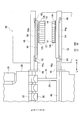
- FIG. 2 is a schematic front view showing the periphery of the stocker (upper stocker and lower stocker) positioned at the mold replacement position.
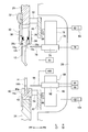
- FIG. 3 is an enlarged cross-sectional view taken along the line III-III in FIG.
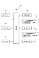
- FIG. 4 is a control block diagram of the bending system according to the embodiment of the present invention.
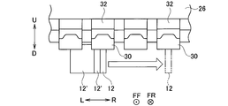
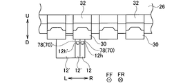
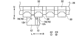
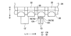
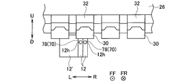
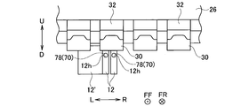
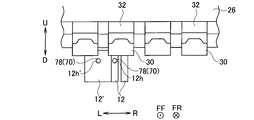
- FIG. 5A is a diagram showing a state in which a predetermined punch die is in contact with another adjacent punch die in a plurality of upper die holders.
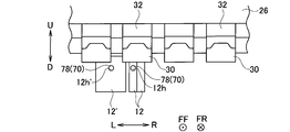
- FIG. 5B is a diagram showing how a predetermined punch die is transferred along a plurality of upper mold holders.
- FIG. 5C is a diagram showing how a predetermined punch die is transferred along a plurality of upper mold holders.
- FIG. 6A is a diagram showing a state in which a plurality of predetermined punch dies are in contact with other adjacent punch dies in the plurality of upper die holders.
- FIG. 6B is a diagram showing an operation for transferring a plurality of predetermined punch dies along a plurality of upper mold holders.
- FIG. 6C is a diagram showing an operation for transferring a plurality of predetermined punch dies along a plurality of upper mold holders.
- FIG. 6D is a diagram showing an operation for transferring a plurality of predetermined punch dies along a plurality of upper mold holders.
- FIG. 6E is a diagram showing an operation for transferring a plurality of predetermined punch dies along a plurality of upper mold holders.
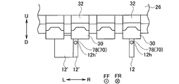
- FIG. 7A is a diagram showing an operation for transferring a plurality of predetermined punch dies along a plurality of upper mold holders.
- FIG. 7B is a diagram showing an operation for transferring a plurality of predetermined punch dies along a plurality of upper mold holders.
- FIG. 7C is a diagram showing an operation for transferring a plurality of predetermined punch dies along a plurality of upper mold holders.
- FIGS. 1 to 7C An embodiment of the present invention will be described with reference to FIGS. 1 to 7C.
- the “left-right direction” is one of the horizontal directions, which is the width direction of the press brake 16 or the mold storage device 56.
- the “front-back direction” is the depth direction of the press brake 16 or the die storage device 56.
- Mold includes an upper mold and a lower mold.
- the “last mold” is the last mold when viewed from the mold transfer direction.
- the “first mold” is the first mold when viewed from the mold transfer method.
- FF indicates the forward direction
- FR indicates the backward direction
- L indicates the left direction
- R indicates the right direction
- U indicates the upward direction
- “D” indicates the downward direction.
- FIGS. 5A to 7C of the locking holes of the plurality of punch dies, only the locking hole 12h in the locked state with the upper die holding member 78 is shown.
- the bending system 10 has a plate shape using a punch die 12 as an automatically replaceable upper die and a die die 14 as a lower die.
- This is a system for bending the work (sheet metal) W of the above.
- a round hole-shaped or elongated hole-shaped locking hole 12h is formed in the central portion of the punch die 12 in the width direction so as to penetrate in the front-rear direction.
- the shank portion 12s as the base portion of the punch die 12 is formed with a locking groove 12g for preventing the punch die 12 from falling (see FIG. 3).
- a round hole-shaped or elongated hole-shaped locking hole 14h is formed in the central portion of the die die 14 in the width direction so as to penetrate in the front-rear direction (see FIG. 3).
- the bending system 10 includes a press brake 16 that bends the work W in cooperation with the punch die 12 and the die die 14.
- the press brake 16 includes a main body frame 18.
- the main body frame 18 has a pair of side plates 20 that are separated from each other in the left-right direction and face each other, and a plurality of connecting members 22 that connect the pair of side plates 20 to each other.
- a lower table 24 extending in the left-right direction is provided at the lower part of the main body frame 18.
- An upper table 26 extending in the left-right direction is provided on the upper part of the main body frame 18 so as to be movable in the up-down direction.
- a hydraulic cylinder 28 is provided on the upper portion of each side plate 20 as a vertical moving portion for moving the upper table 26 in the vertical direction.
- the lower table 24 may be configured to be movable in the vertical direction.
- a servomotor (not shown) may be used instead of the hydraulic cylinder 28 as the vertical movement unit.
- Each upper mold holder 30 holds the punch die 12 detachably.
- Each upper mold holder 30 has, for example, a known configuration shown in Patent Document 2 and has a holder main body 34.
- a front clamp 36 that presses the shank portion 12s of the punch die 12 in the rearward direction is provided on the front side of each holder body 34 so as to be swingable.
- Each front clamp 36 has a claw portion 36c that can be locked in the locking groove 12g of the punch die 12 on the lower end side thereof.
- each holder body 34 On the rear side of each holder body 34, a rear clamp 38 that presses the shank portion 12s of the punch die 12 in a state where the front and back sides are inverted (in the front-rear direction) in the forward direction is provided so as to be swingable.
- Each rear clamp 38 has a claw portion 38c that can be locked in the locking groove 12g of the punch die 12 in a state where the front and back sides are inverted on the lower end side thereof.
- a lower mold holder 40 extending in the left-right direction is provided on the upper side of the lower table 24.
- the lower mold holder 40 holds the die mold 14 in a detachable manner.
- the lower mold holder 40 has, for example, the known configurations shown in Patent Documents 2 and 3, and a holder groove 40 g for inserting the shank portion 14s of the die mold 14 is formed along the left-right direction. There is.
- the lower mold holder 40 has a clamp 42 for fixing (pressing) the die mold 14.
- an upper connecting block 44 extending in the left-right direction is provided.
- a connecting groove 44g for inserting the shank portion 12s of the punch die 12 is formed along the left-right direction.
- the connecting grooves 44g of the upper connecting block 44 are arranged in series along the left-right direction in the gap between the holder main body 34 and the front clamp 36 in the plurality of upper mold holders 30.
- a lower connecting block 46 extending in the left-right direction is provided.
- a connecting groove 46g for inserting the shank portion 14s of the die mold 14 is formed along the left-right direction.
- the connecting groove 46g of the lower connecting block 46 is connected to the holder groove 40g of the lower mold holder 40.
- upper support beams 48 extending in the left-right direction are provided via a plurality of brackets 50 (only one is shown).
- the upper support beam 48 projects to the right of the upper connecting block 44.
- lower support beams 52 extending in the left-right direction are provided via a plurality of brackets 54 (only one is shown).
- the lower support beam 52 projects to the right of the lower connecting block 46.
- mold storage for storing a plurality of punch dies 12 and a plurality of die dies 14 on the left-right side of the press brake 16 (an example around the press brake 16).
- the device 56 is arranged.
- the mold storage device 56 has, for example, the same configuration as the known configurations shown in Patent Document 1 and Patent Document 3.
- the die storage device 56 has a plurality of (only one is shown) upper stockers 58 for holding the plurality of punch dies 12. Although only the upper stocker 58 positioned at the upper replacement position for replacing the punch die 12 is shown, the plurality of upper stockers 58 are arranged along the front-rear direction. Each upper stocker 58 extends in the left-right direction. Each upper stocker 58 is formed with a stocker groove 58g for inserting the shank portion 12s of the punch die 12 along the left-right direction. Each upper stocker 58 has a locking plate 60 that can be locked in the locking groove 12g of the punch die 12.
- the selected upper stocker 58 is configured to be positioned at the upper replacement position by an upper stocker moving mechanism (not shown).
- the upper stocker 58 positioned at the upper replacement position is supported by a pair of upper receiving members 62 provided on the right end side of the front surface of the upper support beam 48.
- the mold storage device 56 has a plurality of lower stockers 64 (only one is shown) for holding the plurality of die molds 14. Although only the lower stocker 64 positioned at the lower replacement position for replacing the die mold 14 is shown, the plurality of lower stockers 64 are arranged along the front-rear direction. Each lower stocker 64 extends in the left-right direction. A stocker groove 64g for inserting the shank portion 14s of the die mold 14 is formed in each lower stocker 64 along the left-right direction.
- the selected lower stocker 64 is configured to be positioned at the lower replacement position by a lower stocker moving mechanism (not shown).
- the lower stocker 64 positioned at the lower replacement position is supported by a pair of lower receiving members 66 provided on the right end side of the front surface of the lower support beam 52.
- an upper guide rail 68 extending in the left-right direction is provided on the back surface (rear surface) of the upper support beam 48.
- a pair of upper die changing units 70 for exchanging the punch die 12 with respect to the plurality of upper die holders 30 and the upper stocker 58 positioned at the upper changing position can move in the left-right direction. It is provided in.
- the pair of upper mold changing units 70 are provided on the back side of the upper table 26 so as to be movable in the left-right direction via the upper support beam 48 and the upper guide rail 68.
- Each upper die changing unit 70 transfers the punch die 12 between the upper die holder 30 and the upper stocker 58 positioned at the upper changing position.
- the pair of upper mold exchange units 70 includes a first upper mold exchange unit 70 and a second upper mold exchange unit 70.
- Each upper mold exchange unit 70 has the same configuration as the known configuration shown in Patent Document 1.
- Each upper mold changing unit 70 has an upper unit main body 72 and an upper support member 74.
- Each upper unit main body 72 is provided on the upper guide rail 68 so as to be movable in the left-right direction.
- Each upper support member 74 is provided on the upper unit main body 72 so as to be movable in the front-rear direction.
- Each upper support member 74 moves in the front-rear direction with respect to each upper unit main body 72 by driving an air cylinder 76 as a front-rear moving portion provided at an appropriate position of each upper unit main body 72.
- the upper support member 74 may be configured to be movable in the vertical direction with respect to the upper unit main body 72.
- Each upper die changing unit 70 has an upper die holding member 78 that is provided on each upper support member 74 so as to be movable in the front-rear direction and holds the punch die 12.
- the tip end side of each upper mold holding member 78 is formed in a round bar shape or a hook shape.
- Each upper die holding member 78 can be engaged with and detached from the locking hole 12h of the punch die 12.
- Each upper mold holding member 78 moves in the front-rear direction with respect to each upper support member 74 by driving an air cylinder 80 as another front-rear moving portion provided at an appropriate position of each upper support member 74.
- Servo motor 82 as a left-right moving part for moving each upper mold changing unit 70 in the left-right direction is provided at an appropriate position of each upper unit main body 72.
- Each servomotor 82 has an encoder 84 as a position detector that detects the position of each upper mold changing unit 70 (each upper mold holding member 78) in the left-right direction.
- Each servomotor 82 includes a first servomotor 82 and a second servomotor 82.
- Each encoder 84 includes a first encoder 84 and a second encoder 84.
- a lower guide rail 86 extending in the left-right direction is provided on the back surface of the lower support beam 52.
- a pair of lower mold replacement units 88 that replace the die mold 14 with respect to the plurality of lower mold holders 40 and the lower stocker 64 positioned at the lower replacement position can be moved in the left-right direction. It is provided in.
- the pair of lower mold changing units 88 are provided on the back side of the lower table 24 so as to be movable in the left-right direction via the lower support beam 52 and the lower guide rail 86.
- Each lower mold exchange unit 88 transfers the die mold 14 between the lower mold holder 40 and the lower stocker 64 positioned at the lower exchange position.
- the pair of lower mold exchange units 88 includes a first lower mold exchange unit 88 and a second lower mold exchange unit 88.
- Each lower mold exchange unit 88 has the same configuration as the known configuration shown in Patent Document 1.
- Each lower mold replacement unit 88 has a lower unit main body 90 and a lower support member 92.
- the lower unit main body 90 is provided on the lower guide rail 86 so as to be movable in the left-right direction.
- the lower support member 92 is provided on the lower unit main body 90 so as to be movable in the front-rear direction and the up-down direction.
- Each lower support member 92 moves in the front-rear direction with respect to each lower unit main body 90 by driving an air cylinder 94 as a front-rear moving portion provided at an appropriate position of each lower unit main body 90.
- Each lower support member 92 moves in the vertical direction with respect to each lower unit main body 90 by driving an air cylinder 96 as a vertical moving portion provided at an appropriate position of each lower unit main body 90.
- Each lower mold exchange unit 88 has a lower mold holding member 98 that is provided on each lower support member 92 so as to be movable in the front-rear direction and holds the die mold 14.
- the tip end side of each lower mold holding member 98 is formed in a round bar shape or a hook shape.
- Each lower mold holding member 98 can be engaged with and detached from the locking hole 14h of the die mold 14.
- Each lower mold holding member 98 moves in the front-rear direction with respect to each lower support member 92 by driving an air cylinder 100 as another front-rear moving portion provided at an appropriate position of each lower support member 92.
- Servo motors 102 are provided at appropriate positions on each lower unit main body 90 as left-right moving portions for moving each lower mold changing unit 88 in the left-right direction.
- Each servomotor 102 has an encoder 104 as a position detector that detects the position of each lower mold replacement unit 88 (each lower mold holding member 98) in the left-right direction.
- Each servomotor 102 includes a first servomotor 102 and a second servomotor 102.
- Each encoder 104 includes a first encoder 104 and a second encoder 104.
- the bending processing system 10 includes a control device (NC device) 106 as a control unit.
- the control device 106 controls the hydraulic cylinder 28 and the like based on the machining program, and controls the mold storage device 56 and the upper mold changing unit 70 and the like based on the mold changing program.
- the control device 106 is composed of a computer. Encoders 84, 104 and the like are connected to the control device 106.
- the control device 106 has a memory (not shown) for storing a machining program, a mold change program, and the like, and a CPU (not shown) for executing the machining program and the die change program.
- the control device 106 (See FIG. 5A), so that the upper die holding member 78 of the first upper die changing unit 70 holds the predetermined punch die 12 in a state of being locked in the locking hole 12h of the predetermined punch die 12. , Controls the first upper mold changing unit 70 and the first servomotor 82. Further, the control device 106 is in a state where the upper die holding member 78 of the second upper die changing unit 70 is locked in the locking hole 12h'of the other punch die 12', and the other punch die 12'.
- the second upper mold changing unit 70 and the second servomotor 82 are controlled so as to hold the above (see FIG. 5B). Subsequently, the control device 106 obtains the detection result from the first encoder 84 in a state where the movement of the second upper mold exchange unit 70 in the left-right direction is stopped, and the first upper mold exchange unit Each servomotor 82 is controlled so that the 70 moves in the left-right direction until it reaches the target position (see FIG. 5C).
- control device 106 can grasp that the predetermined punch dies 12 are in contact with other adjacent punch dies 12'in the plurality of upper die holders 30 based on the die change program. it can.
- the control device 106 when the control device 106 has a plurality of predetermined punch dies 12 (see FIG. 6A), the control device 106 has a plurality of predetermined upper die holding members 78 of the first upper die changing unit 70.
- the last punch die 12 of the punch dies 12 (the punch die 12 on the left side in FIGS. 6A to 6E) is held in the locking hole 12h so as to hold the last punch die 12.
- 1 Controls the upper mold changing unit 70 and the first servomotor 82. Further, the control device 106 is in a state where the upper die holding member 78 of the second upper die changing unit 70 is locked in the locking hole 12h'of the other punch die 12', and the other punch die 12'.
- the second upper mold changing unit 70 and the second servomotor 82 are controlled so as to hold the above (see FIG. 6B). Subsequently, the control device 106 obtains the detection result from the first encoder 84 in a state where the movement of the second upper mold exchange unit 70 in the left-right direction is stopped, and the first upper mold exchange unit Each servomotor 82 is controlled so that the 70 moves in the left-right direction by a predetermined amount (see FIG. 6C).
- the predetermined amount is a movement amount set in advance for separating the last punch die 12 from the other punch die 12'.
- the upper die holding member 78 of the first upper die changing unit 70 is the first punch die 12 of the plurality of predetermined punch dies (the right punch die in FIGS. 6A to 6E).
- the first upper die changing unit 70 and the first servomotor 82 are controlled so as to hold the leading punch die 12 in a state of being locked in the locking hole 12h of the die 12).
- the control device 106 holds the tail punching die 12 in a state where the upper die holding member 78 of the second upper die changing unit 70 is locked in the locking hole 12h of the tail punching die 12.
- the second upper mold changing unit 70 and the second servomotor 82 are controlled (see FIG. 6D).
- control device 106 obtains the detection results from the encoders 84 and moves the upper mold changing unit 70 in the left-right direction synchronously (or asynchronously) until the target position is reached.
- the servomotor 82 is controlled (see FIG. 6E).
- the plurality of predetermined punch dies 12 may have an intermediate punch die (not shown) between the first punch die 12 and the last punch die 12. In other words, the number of predetermined punch dies 12 may be three or more. Further, from the state shown in FIG. 6B, each servomotor 82 is controlled so that the first upper mold changing unit 70 moves in the left-right direction until it reaches the target position instead of moving in the left-right direction by a predetermined amount. You may.
- control device 106 is before the upper die holding member 78 of the first upper die changing unit 70 holds the last punch die 12 when there are a plurality of predetermined punch dies 12.
- control device 106 may control each upper mold changing unit 70 and each servomotor 82 as follows.
- the control device 106 holds the leading punch die 12 in a state where the upper die holding member 78 of the first upper die changing unit 70 is locked in the locking hole 12h of the leading punch die 12. As described above, the first upper mold changing unit 70 and the first servomotor 82 are controlled. Further, the control device 106 holds the last punch die 12 in a state where the upper die holding member 78 of the second upper die changing unit 70 is locked in the locking hole 12h of the last punch die 12. As described above, the second upper mold changing unit 70 and the second servomotor 82 are controlled (see FIG. 7A).
- the control device 106 obtains the detection result from the first encoder 84 in a state where the movement of the second upper mold exchange unit 70 in the left-right direction is stopped, and the first upper mold exchange unit Each servomotor 82 is controlled so that the 70 moves in the left-right direction by a predetermined amount (see FIG. 7B).
- the predetermined amount means a movement amount set in advance for separating the leading punch die 12 from the trailing punch die 12.
- the predetermined punch die 12 which is the replacement target (transfer target) is not an adjacent replacement target. Even when it is in contact with the punch die 12', each upper die changing unit 70 and each servomotor 82 are controlled in the same manner as described above. Further, in the control device 106, in the lower stocker 64 positioned at the upper and lower replacement positions of the lower mold holder 40, a predetermined die mold 14 which is a replacement target (transfer target) is adjacent to another die mold which is not a replacement target. Even when in contact with the mold (not shown), each lower mold replacement unit 88 and each servomotor 102 are controlled in the same manner as described above.
- the control when the punch die 12 is transferred from the upper die holder 30 to the upper stocker 58 positioned at the upper replacement position will be described.
- the control device 106 controls the servomotor 82 to move the upper die changing unit 70 in the left-right direction, and locks the punch die 12 in which the upper die holding member 78 is mounted on the upper die holder 30. Facing 12h.
- the control device 106 causes the upper die holding member 78 to hold the punch die 12 while engaging the upper die holding member 78 with the locking hole 12h of the punch die 12.
- the control device 106 controls the servomotor 82 to move the upper die changing unit 70 to the right, transfers the punch die 12 to the right, and separates the punch die 12 from the upper die holder 30.
- control device 106 controls the servomotor 82 to move the upper die changing unit 70 to the right, transfers the punch die 12 to the right, and attaches it to the upper stocker 58. After that, the control device 106 disengages the upper die holding member 78 from the locking hole 12h of the punch die 12 to release the holding state of the punch die 12 by the upper die holding member 78.
- the punch die 12 may be moved to the back side (rear) of the upper table 26 by the upper die changing unit 70.
- the die mold 14 When the die mold 14 is transferred between the lower mold holder 40 and the lower stocker 64 positioned at the lower replacement position, the same operation as described above is performed. As a result, the die mold 14 mounted on the lower mold holder 40 and the die mold 14 mounted on the lower stocker 64 can be automatically replaced.
- the lower mold exchange unit 88 may move the die mold 14 in the vertical direction.
- the mold transfer method according to the present embodiment is a method of transferring the molds 12 and 14 along the mold holders 30 and 40 or the stockers 58 and 64 positioned at the replacement positions.
- control device 106 controls each upper mold changing unit 70 and each servomotor 82 to operate as follows.
- the predetermined punch die 12 is held in a state where the upper die holding member 78 of the first upper die changing unit 70 is locked in the locking hole 12h of the predetermined punch die 12. Further, in a state where the upper die holding member 78 of the second upper die changing unit 70 is locked in the locking hole 12h'of the other punch die 12', the other punch die 12'is held ( See FIG. 5B). Subsequently, with the movement of the second upper mold changing unit 70 in the left-right direction stopped, the first upper mold changing unit 70 is set to the target position while acquiring the detection result from the first encoder 84. Move left and right until it reaches (see FIG. 5C).
- the other punch dies 12' are not dragged by the predetermined punch dies 12, so that the positions of the other punch dies 12'do not shift. Therefore, only the predetermined punch die 12 to be replaced can be transferred in the left-right direction by the upper die changing unit 70 without performing post-processing on the side surface of the punch die 12.
- control device 106 is used for each upper die changing unit 70 and each servomotor. By controlling 82, it operates as follows.
- the last punch die Hold the mold 12. Further, in a state where the upper die holding member 78 of the second upper die changing unit 70 is locked in the locking hole 12h'of the other punch die 12', the other punch die 12'is held ( See FIG. 6B). Subsequently, with the second upper mold changing unit 70 stopped moving in the left-right direction, the first upper mold changing unit 70 moves in the left-right direction by a predetermined amount (see FIG. 6C). As a result, the plurality of predetermined punch dies 12 can be separated from the other punch dies 12'.
- each upper mold changing unit 70 moves synchronously (or asynchronously) in the left-right direction until it reaches the target position (see FIG. 6E).
- the other punch dies 12' are not dragged by the plurality of predetermined punch dies 12, so that the positions of the other punch dies 12'do not shift. Therefore, without post-processing the side surface of the punch die 12, only the plurality of predetermined punch dies 12 to be replaced by the upper die changing unit 70 are moved in the left-right direction along the plurality of upper die holders 30. Can be transferred.
- control device 106 causes each upper die changing unit 70 and By controlling each servomotor 82, it may be operated as follows.
- the leading punch die 12 is held in a state where the upper die holding member 78 of the first upper die changing unit 70 is locked in the locking hole 12h of the leading punch die 12. Further, the upper die holding member 78 of the second upper die changing unit 70 holds the last punch die 12 in a state of being locked in the locking hole 12h of the last punch die 12 (see FIG. 7A). .. Subsequently, with the second upper mold changing unit 70 stopped moving in the left-right direction, the first upper mold changing unit 70 moves in the left-right direction by a predetermined amount. As a result, the leading punch die 12 can be separated from the trailing punch die 12.
- the transfer direction of the predetermined punch die 12 is shown as the right direction, and the upper die changing unit 70 on the right side is referred to as the first upper die changing unit 70, and the left side.
- the upper mold exchange unit 70 of the above is used as a second upper mold exchange unit 70.
- the transfer direction of the predetermined punch die 12 is to the left, the upper die changing unit 70 on the left side becomes the first upper die changing unit 70, and the upper die changing unit 70 on the right side becomes the second upper die.
- the replacement unit 70 will be used. That is, when the transfer direction of the predetermined punch die 12 is reversed, the first upper die exchange unit 70 and the second upper die exchange unit 70 are exchanged.
- a predetermined punch die 12 which is a replacement target (transfer target) is adjacent to another punch die which is not a replacement target. Even when it is in contact with 12', the control device 106 controls each upper type exchange unit 70 and each servomotor 82 to operate in the same manner as described above.
- the predetermined die mold 14 (or a plurality of predetermined die molds 14) to be replaced (transfer target) is not an adjacent replacement target.
- the control device 106 controls each lower die changing unit 88 and each servomotor 102 to operate in the same manner as described above.
- the other die dies are not dragged by the predetermined die dies 14 (or a plurality of predetermined die dies 14), so that the position of the other die dies does not shift.
- the predetermined die die 14 (or a plurality of predetermined die dies 14) is placed along the lower die holder 40 by the lower die changing unit 88. It can be transferred in the left-right direction.
- the bending processing system 10 can stably perform the operation related to the automatic replacement of the molds 12 and 14 while suppressing the increase in the manufacturing cost of the molds 12 and 14.
- the mold changing units 70 and 88 may be provided on the front side of the tables 26 and 24 so as to be movable in the left-right direction.
- the location of the mold storage device 56 may be other than the lateral side of the press brake 16 in the left-right direction as long as it is around the press brake 16.
- the present invention has, for example, the following configuration.
- the bending system is arranged around the press brake and has a die storage device having a plurality of stockers extending in the left-right direction and capable of holding a plurality of dies, and the press brake table on the back side or the front side.
- a first mold exchange unit and a second mold exchange that are provided so as to be movable in the left-right direction and exchange dies for the mold holder of the press brake and the stocker selected from the plurality of stockers.
- the unit, the left-right moving unit that moves the first mold exchange unit and the second mold exchange unit in the left-right direction, the first mold exchange unit, and the second mold exchange unit.
- a control unit that controls the left-right movement unit.
- the first mold exchange unit can be engaged with and detached from the locking hole of the mold, can hold the mold, and moves in the left-right direction together with the first mold exchange unit. It has a mold holding member.
- the second mold exchange unit can be engaged with and detached from the locking hole of the mold, can hold the mold, and moves in the left-right direction together with the second mold exchange unit. It has a mold holding member.
- the second mold is held in a state of being locked to, and subsequently, the first mold exchange unit moves to the left and right while the movement of the second mold exchange unit in the left-right direction is stopped.
- the first mold exchange unit, the second mold exchange unit, and the left-right moving unit are controlled so as to move in the direction.
- the second mold that is not the exchange target is not dragged by the first mold that is the exchange target, the position of the second mold does not shift.
- the first mold to be replaced can be transferred in the left-right direction by the first and second mold replacement units without post-processing the side surface of the mold. Therefore, it is possible to stably perform the operation related to the automatic replacement of the mold while suppressing the increase in the manufacturing cost of the mold.
- the control unit uses the first mold holding member as the second mold among the plurality of first dies.
- the last mold is held in a state of being locked in the locking hole of the last mold in contact, and the second mold holding member engages with the locking hole of the second mold.
- the second mold is held in the stopped state, and then the first mold exchange unit moves in the left-right direction while the movement of the second mold exchange unit in the left-right direction is stopped.
- the first mold holding member holds the first mold in a state where the first mold holding member is locked in the locking hole of the first mold among the plurality of first molds.
- the second mold holding member holds the last mold in a state of being locked in the locking hole of the last mold, and subsequently, the first mold exchange unit and the first mold are replaced.
- the first mold exchange unit, the second mold exchange unit, and the left-right movement unit may be controlled so that the mold exchange unit 2 moves in the left-right direction.
- the first mold holding member is placed in the locking hole of the leading mold before the first mold holding member holds the last mold.
- the leading mold is held in a locked state
- the trailing mold is held in a state where the second mold holding member is locked in the locking hole of the trailing mold, and then Then, while the movement of the second mold exchange unit in the left-right direction is stopped, the first mold exchange unit moves in the left-right direction by a predetermined amount.
- the unit, the second mold changing unit, and the left-right moving unit may be controlled.
- a first mold exchange unit and a second mold exchange unit provided so as to be movable in the left-right direction on the back side or the front side of the press brake table are used.
- the first mold to be replaced is adjacent to the replacement target.
- the first mold holding member of the first mold changing unit is locked in the locking hole of the first mold when the second mold is in contact with the first mold.
- the first mold is held by the mold holding member of 1
- the second mold holding member of the second mold changing unit is locked in the locking hole of the second mold.
- the second mold is held by the second mold holding member in the state of being in the state, and subsequently, the movement of the second mold exchange unit in the left-right direction is stopped.
- 1 is provided with moving the mold changing unit in the left-right direction.
- the second mold that is not the exchange target is not dragged by the first mold that is the exchange target, the position of the second mold does not shift.
- the first mold to be replaced can be transferred in the left-right direction by the first and second mold replacement units without post-processing the side surface of the mold. Therefore, it is possible to stably perform the operation related to the automatic replacement of the mold while suppressing the increase in the manufacturing cost of the mold.
- the first mold holding member is in contact with the second mold among the plurality of first molds.
- the last mold is held by the first mold holding member in a state of being locked in the locking hole of the last mold, and the second mold holding member is held by the second mold.
- the second mold is held by the second mold holding member in a state of being locked in the locking hole of the above, and subsequently, the movement of the second mold exchange unit in the left-right direction is performed.
- the first mold changing unit is moved in the left-right direction by a predetermined amount, and then the first mold holding member is moved to the head of the plurality of first molds.
- the first mold holding member holds the first mold in a state of being locked in the locking hole of the mold, and the second mold holding member is engaged with the last mold.
- the last mold is held by the second mold holding member in a state of being locked to the stop hole, and subsequently, the first mold exchange unit and the second mold exchange unit are held. It may be provided with the movement in the left-right direction.
- the first mold holding member is locked in the locking hole of the leading mold before the last mold is held by the first mold holding member.
- the first mold holding member holds the leading mold
- the second mold holding member is locked in the locking hole of the last mold.
- the first mold exchange unit is held in a state where the last mold is held by the mold holding member of No. 1 and subsequently, the movement of the second mold exchange unit in the left-right direction is stopped. It may be provided that it moves by a predetermined amount in the left-right direction.
Landscapes
- Engineering & Computer Science (AREA)
- Mechanical Engineering (AREA)
- Mounting, Exchange, And Manufacturing Of Dies (AREA)
- Bending Of Plates, Rods, And Pipes (AREA)
Abstract
Un premier élément de maintien (78) de dé d'une première unité de remplacement de dé (70) maintient un premier dé (12), qui doit être remplacé, dans un état verrouillé dans un trou de verrouillage (12h) du premier dé (12). Un second élément de maintien (78) de dé d'une seconde unité de remplacement (70) de dé maintient un second dé (12'), qui n'est pas à remplacer, dans un état de verrouillage dans un trou de verrouillage (12h') du second dé (12'). La première unité de remplacement (70) de dé se déplace ensuite dans un sens gauche-droite, le déplacement de la seconde unité de remplacement (70) de dé dans le sens gauche-droite étant interrompu.
Priority Applications (3)
| Application Number | Priority Date | Filing Date | Title |
|---|---|---|---|
| CN202080036296.6A CN113840672B (zh) | 2019-05-16 | 2020-05-08 | 弯曲加工系统以及金属模具输送方法 |
| EP20804835.5A EP3970874B1 (fr) | 2019-05-16 | 2020-05-08 | Système de pliage et procédé de transfert de l'outil |
| US17/610,484 US12145191B2 (en) | 2019-05-16 | 2020-05-08 | Bending system and tool transport method |
Applications Claiming Priority (2)
| Application Number | Priority Date | Filing Date | Title |
|---|---|---|---|
| JP2019-092890 | 2019-05-16 | ||
| JP2019092890A JP6741824B1 (ja) | 2019-05-16 | 2019-05-16 | 曲げ加工システム及び金型移送方法 |
Publications (1)
| Publication Number | Publication Date |
|---|---|
| WO2020230730A1 true WO2020230730A1 (fr) | 2020-11-19 |
Family
ID=72047802
Family Applications (1)
| Application Number | Title | Priority Date | Filing Date |
|---|---|---|---|
| PCT/JP2020/018708 Ceased WO2020230730A1 (fr) | 2019-05-16 | 2020-05-08 | Système de pliage et procédé de transfert de dé |
Country Status (5)
| Country | Link |
|---|---|
| US (1) | US12145191B2 (fr) |
| EP (1) | EP3970874B1 (fr) |
| JP (1) | JP6741824B1 (fr) |
| CN (1) | CN113840672B (fr) |
| WO (1) | WO2020230730A1 (fr) |
Families Citing this family (2)
| Publication number | Priority date | Publication date | Assignee | Title |
|---|---|---|---|---|
| EP4487977A1 (fr) * | 2018-07-17 | 2025-01-08 | Amada Co., Ltd. | Procédé d'ajustement d'une matrice supérieure divisée sur un support de matrice supérieure disposé sur une table supérieure d'un presse-plieuse, dispositif d'échange de matrice et dispositif de stockage de matrice |
| CN120244067A (zh) * | 2025-06-04 | 2025-07-04 | 靖江市英正五金科技有限公司 | 一种液压废钢自动送料剪切机 |
Citations (7)
| Publication number | Priority date | Publication date | Assignee | Title |
|---|---|---|---|---|
| JPS5841800B2 (ja) | 1980-08-29 | 1983-09-14 | 富士通株式会社 | セラミック多層基板の形成方法 |
| JPS5947861B2 (ja) | 1976-12-28 | 1984-11-21 | 日本電気株式会社 | アラ−ム表示付プラズマ・ディスプレイ・パネル |
| JPH1110235A (ja) * | 1997-06-20 | 1999-01-19 | Amada Co Ltd | 曲げ加工機における金型交換方法および金型格納装置並びに曲げ加工システム |
| JP2000071028A (ja) * | 1998-08-28 | 2000-03-07 | Amada Co Ltd | 金型及び金型交換装置 |
| JP2006000855A (ja) * | 2003-06-23 | 2006-01-05 | Amada Co Ltd | 曲げ加工装置及びその方法並びに曲げ金型 |
| JP4672868B2 (ja) | 1999-01-13 | 2011-04-20 | 株式会社アマダ | 曲げプレスシステム |
| JP2019092890A (ja) | 2017-11-22 | 2019-06-20 | 株式会社三洋物産 | 遊技機 |
Family Cites Families (16)
| Publication number | Priority date | Publication date | Assignee | Title |
|---|---|---|---|---|
| JPS5841800U (ja) | 1981-09-16 | 1983-03-19 | 三菱重工業株式会社 | 条材などの持ち上げ具 |
| JP2004322199A (ja) * | 2003-04-30 | 2004-11-18 | Amada Co Ltd | 曲げ加工装置 |
| DE602006020699D1 (de) * | 2006-06-01 | 2011-04-28 | Wila Bv | Auswechselbares Werkzeug/Manipulator Kombination |
| JP5841800B2 (ja) | 2011-10-20 | 2016-01-13 | 株式会社アマダホールディングス | 上型ホルダ |
| JP2013111610A (ja) * | 2011-11-29 | 2013-06-10 | Amada Co Ltd | 板材曲げ加工装置 |
| JP5965214B2 (ja) * | 2012-05-31 | 2016-08-03 | 株式会社アマダホールディングス | 曲げ加工装置の動作制御方法及び動作制御システム、並びに、曲げ加工作業のトレーニングシステム及びトレーニング方法 |
| JP2014004604A (ja) * | 2012-06-25 | 2014-01-16 | Amada Co Ltd | 金型搭載用ストッカ、金型格納装置、並びに金型・ハンド格納装置及びロボットによる金型交換方法とその制御装置 |
| EP3330015B1 (fr) * | 2014-02-10 | 2023-06-21 | SALVAGNINI ITALIA S.p.A. | Machine de cintrage de tôle |
| JP5947861B2 (ja) | 2014-10-24 | 2016-07-06 | 株式会社アマダホールディングス | プレスブレーキの金型着脱交換方法及び金型収納装置 |
| IT201700052500A1 (it) * | 2017-05-15 | 2018-11-15 | Salvagnini Italia Spa | Macchina piegatrice per lamiere metalliche |
| CN208004538U (zh) * | 2018-03-24 | 2018-10-26 | 北京铂纳艺境视觉技术有限公司 | 液压板料折弯机 |
| WO2020226084A1 (fr) * | 2019-05-07 | 2020-11-12 | 株式会社アマダ | Frein à pression |
| CN113825572B (zh) * | 2019-05-16 | 2024-03-15 | 株式会社天田集团 | 弯曲加工系统以及金属模具错位修正方法 |
| JP1672868S (ja) | 2020-03-27 | 2020-11-16 | 乗用自動車 | |
| WO2022059382A1 (fr) * | 2020-09-17 | 2022-03-24 | 村田機械株式会社 | Moule supérieur et système de traitement |
| JP2023041024A (ja) * | 2021-09-10 | 2023-03-23 | 株式会社アマダ | 曲げ加工システム、及び金型の配置方法 |
-
2019
- 2019-05-16 JP JP2019092890A patent/JP6741824B1/ja active Active
-
2020
- 2020-05-08 WO PCT/JP2020/018708 patent/WO2020230730A1/fr not_active Ceased
- 2020-05-08 US US17/610,484 patent/US12145191B2/en active Active
- 2020-05-08 EP EP20804835.5A patent/EP3970874B1/fr active Active
- 2020-05-08 CN CN202080036296.6A patent/CN113840672B/zh active Active
Patent Citations (7)
| Publication number | Priority date | Publication date | Assignee | Title |
|---|---|---|---|---|
| JPS5947861B2 (ja) | 1976-12-28 | 1984-11-21 | 日本電気株式会社 | アラ−ム表示付プラズマ・ディスプレイ・パネル |
| JPS5841800B2 (ja) | 1980-08-29 | 1983-09-14 | 富士通株式会社 | セラミック多層基板の形成方法 |
| JPH1110235A (ja) * | 1997-06-20 | 1999-01-19 | Amada Co Ltd | 曲げ加工機における金型交換方法および金型格納装置並びに曲げ加工システム |
| JP2000071028A (ja) * | 1998-08-28 | 2000-03-07 | Amada Co Ltd | 金型及び金型交換装置 |
| JP4672868B2 (ja) | 1999-01-13 | 2011-04-20 | 株式会社アマダ | 曲げプレスシステム |
| JP2006000855A (ja) * | 2003-06-23 | 2006-01-05 | Amada Co Ltd | 曲げ加工装置及びその方法並びに曲げ金型 |
| JP2019092890A (ja) | 2017-11-22 | 2019-06-20 | 株式会社三洋物産 | 遊技機 |
Also Published As
| Publication number | Publication date |
|---|---|
| JP2020185598A (ja) | 2020-11-19 |
| EP3970874A1 (fr) | 2022-03-23 |
| JP6741824B1 (ja) | 2020-08-19 |
| EP3970874B1 (fr) | 2023-05-31 |
| EP3970874A4 (fr) | 2022-07-13 |
| US12145191B2 (en) | 2024-11-19 |
| CN113840672B (zh) | 2023-08-15 |
| US20220219221A1 (en) | 2022-07-14 |
| CN113840672A (zh) | 2021-12-24 |
Similar Documents
| Publication | Publication Date | Title |
|---|---|---|
| JP4582621B2 (ja) | 曲げ加工装置 | |
| JP6789356B1 (ja) | 曲げ加工システム及び金型位置ずれ補正方法 | |
| US20250289046A1 (en) | Bending system and correcting method for tool misalignment | |
| JP6800364B1 (ja) | 曲げ加工システム | |
| US12036599B2 (en) | Press brake | |
| WO2020230730A1 (fr) | Système de pliage et procédé de transfert de dé | |
| JP6920222B2 (ja) | 金型有無検出方法及びプレスブレーキ | |
| JP7320439B2 (ja) | 分割金型の配置方法及びプレスブレーキ | |
| JP2021514845A5 (fr) | ||
| JP6785392B1 (ja) | プレスブレーキ | |
| JP6641420B2 (ja) | 分割金型の装着方法及びプレスブレーキ | |
| JP7182535B2 (ja) | 曲げ加工システム及び給脂ユニット | |
| JP2019181484A (ja) | 金型交換装置、プレス機械、及び金型交換方法 | |
| JP3783944B2 (ja) | 板材曲げ加工機の押え型取り付け構造 | |
| JP5508688B2 (ja) | 製品搬出方法及び装置 | |
| JP4824977B2 (ja) | プレスブレーキ | |
| WO2023112663A1 (fr) | Dispositif de matrice d'insert, presse plieuse et procédé de pliage de presse plieuse | |
| TWM545029U (zh) | 板材切削裝置 | |
| WO2022224943A1 (fr) | Système de cintrage et procédé d'agencement de moule divisé | |
| JP2022166825A (ja) | 曲げ加工システム、及び分割金型の配置方法 | |
| WO2005120740A1 (fr) | Filiere de rabattage et appareil a filiere de rabattage | |
| JP2004034123A (ja) | 金型取付機構及びプレス機械 |
Legal Events
| Date | Code | Title | Description |
|---|---|---|---|
| 121 | Ep: the epo has been informed by wipo that ep was designated in this application |
Ref document number: 20804835 Country of ref document: EP Kind code of ref document: A1 |
|
| NENP | Non-entry into the national phase |
Ref country code: DE |
|
| WWE | Wipo information: entry into national phase |
Ref document number: 2020804835 Country of ref document: EP |
|
| ENP | Entry into the national phase |
Ref document number: 2020804835 Country of ref document: EP Effective date: 20211216 |